Steam flow rate (Kg/hour) 12 11 10 9 8 7 6 5 4 3 2 1 0 100 200 300 400 500 600 50 150 250 350 450 550 UPL 0034 UPL 0114 Steam pressure (Ate) Flow rate (l/hour) 600 1000 1500 2000 2500 3000 4000 5000 6000 7000 8000 10.000 95 90 80 70 60 50 40 2 3 4 5 6 7 8 9 10 Temperature (°C) Temperature (°C) Steam pressure (bar) Steam pressure (bar) Flow rate (l/hour) 600 1000 1500 2000 2500 3000 4000 5000 6000 8000 10.000 95 90 80 70 60 50 40 2 3 4 5 6 7 8 9 10 Steam Cool water Hot water PRESSURE / CAPACITY AT WATER TEMPERATURE = 15°C STEAM CONSUMPTION CHART UPL 0114 B3 UPL steam operated heaters provide a simple, economic and noiseless solution to produce hot water in production plants. Simply connect the mixer inlet to the cold water and steam lines to have a ready supply of hot sanitary water for your cleaning operations. This heating process is extremely efficient, cost-saving and needs no stock as it provides the volume of hot water your need. Two inlet valves allow to adjust the temperature which can be read on the thermometer placed in the mixer front. The tables below give capacity of hot water (l/hour) for inlet water temperature of 15°C, as a function of steam pressure. STEAM HEATERS STEAM HEATERS Steam inlet Globe valve PN25, with metal sealing seat. Max temperature 180°C Max working pressure 12 bar Water inlet Globe valve PN16, with metal sealing or PTFE seat. 136 4.7 L mm W kg Code UPL 0034 xx UPL 0114 xx 196 183 H1 mm 275 356 H mm 530 3/4" UF inch 3/4" RFS inch 3/4" RFW inch 1 1 /4" 1 1 /4" 1 1 /4" 15.7 UPL HEATER CODE THREAD B2 B2 - AISI 304 Stainless steel - AISI 304 Stainless steel 0034 B2 ( STEAM HEATERS ) UPL 100 www.pnr.eu MATERIAL STEAM HEATERS ■ Max operating temperature ■ Max steam pressure LP 10 bar LT 90°C ■ Thread size ■ Thread specification BSP, NPT 3/4", 1 1 /4" ■ Typical applications food, chemical and paper industry ■ Materials B2 AISI 304 Stainless steel EX.: UPL 0034 B2 HOW TO MAKE UP THE PRODUCT CODE RFW RFS L H H1 UF 60 90 30 110 0 130 UPL 0034 B3 ■ ■

Welcome message from author
This document is posted to help you gain knowledge. Please leave a comment to let me know what you think about it! Share it to your friends and learn new things together.
Transcript

Steam flow rate (Kg/hour)
12
11
10
9
8
7
6
5
4
3
2
1
0100 200 300 400 500 60050 150 250 350 450 550
UPL 0034 UPL 0114
Stea
m p
ress
ure
(Ate
)
Flow rate (l/hour)600 1000 1500 2000 2500 3000 4000 5000 6000 7000 8000 10.000
9590
80
70
60
50
40
2 3 4 5 6 7 8 9 10
Tem
pera
ture
(°C
)Te
mpe
ratu
re (°
C)
Steam pressure (bar)
Steam pressure (bar)
Flow rate (l/hour)600 1000 1500 2000 2500 3000 4000 5000 6000 8000 10.000
9590
80
70
60
50
40
2 3 4 5 6 7 8 9 10
Steam Cool water
Hot water
PRESSURE / CAPACITY AT WATER TEMPERATURE = 15°C STEAM CONSUMPTION CHART
UPL 0114 B3
UPL steam operated heaters provide a simple, economic and noiseless solution to produce hot water in production plants. Simply connect the mixer inlet to the cold water and steam lines to have a ready supply of hot sanitary water for your cleaning operations. This heating process is extremely efficient, cost-saving and needs no stock as it provides the volume of hot water your need. Two inlet valves allow to adjust the temperature which can be read on the thermometer placed in the mixer front.
The tables below give capacity of hot water (l/hour) for inlet water temperature of 15°C, as a function of steam pressure.
STEAM HEATERSSTEAM HEATERS
Steam inletGlobe valve PN25, with metal sealing seat.Max temperature 180°CMax working pressure 12 bar
Water inletGlobe valve PN16, with metal sealing or PTFE seat.
136 4.7
Lmm
Wkg
Code
UPL 0034 xx
UPL 0114 xx 196
183
H1mm
275
356
Hmm
530
3/4"
UFinch
3/4"
RFSinch
3/4"
RFWinch
11/4" 11/4" 11/4" 15.7
UPL
HEATER CODE
THREAD
B2B2 - AISI 304 Stainless steel- AISI 304 Stainless steel0034 B2
( STEAM HEATERS ) UPL
100
www.pnr.eu
MATERIAL
ST
EA
M H
EA
TE
RS
■ Max operating temperature■ Max steam pressure LP 10 bar
LT 90°C
■ Thread size■ Thread specification BSP, NPT
3/4", 11/4"
■ Typical applications food, chemical and paper industry
■ Materials B2 AISI 304 Stainless steel
EX.: UPL 0034 B2
HOW TO MAKE UP THEPRODUCT CODE
RFWRFS
L
H
H1
UF
60 90
30 110
0 130
UPL 0034 B3
■
■

UMU AD20 B2HSBUMU AD20 B2HSBSpray gun is not includedSpray gun is not included
UMU A/B models are basic manual rewind hose reels. The hose can be pull out to the desired length, oriented for release and safely returned into initial position after use. It can be assembled on a mobile cart or fixed to floor, wall or ceiling. Its construction is industrial grade, it's safe for operators, wear-resistant, and leak-free. They are specially designed for swivel nozzles and can be customized in length, materials, operating pressure and temperature to satisfy your requirements.
UMU A/B - MANUAL REWIND HOSE REELSUMU A/B - MANUAL REWIND HOSE REELS
UMU G/H models are auto-rewind hose reels with multi-position release, very useful and practical for frequent cleaning operations. The hose can be easily pulled out from the reel for the desired length and locked in place during use. When washing is completed, a short further pull activates a spring powered automatic rewind mechanism that returns the hose onto the reel. It's suitable for a variety of industrial environments, wear-resistant, robust in construction and designed to mount floor, wall, ceiling or cart.
UMU G/H - AUTO-REWIND HOSE REELSUMU G/H - AUTO-REWIND HOSE REELS
UMU HD20 B2HSB
1"
1"
3/8"
1/2"
3/8"
1/2"
3/8"
1/2"
10
20
20
20
50
35
70
50
12
13
9
12
13
500
500
390
500
500
460
460
330
460
460
270
340
300
270
340
20
200
1"
1/2"
1"
1/2"
20
10
Code
B2LSB
B2LSB
UMU BF10
UMU BF20
UMU AC20 B2HSB
UMU AD20 B2HSB
UMU BC50 B2HSB
UMU BD35 B2HSB
UMU BC70 B2HSB
UMU BD50 B2HSB
inch m kg mm mm mmbar inch inch mm
MFDIE ULP LF W DE H S Swivel code
on request
3/4"
3/4"
1"
1"
1/2"
1/2"
3/8"
1/2"
13
8
18
15
15
20
20
20
18
18
24
24
13
18
18
18
530
530
550
530
550
530
430
550
260
300
550
550
430
550
300 XUM US20 B2
XUM US22 B2
XUM US15 B2
XUM US20 B2
480
230
300
20
20
200
1"
1"
1/2"
1"
1"
1/2"
20
20
10
Code
UMU HE13 B2LSB
UMU HF08 B2LSB
UMU HE18 B2LSB
UMU HF15 B2LSB
UMU GD15 B2HSB
UMU GD20 B2HSB
UMU HC20 B2HSB
UMU HD20 B2HSB
Swivel code
UMU A / B ( MANUAL REWIND HOSE REELS )
UMU G / H ( AUTO - REWIND HOSE REELS )
101
www.pnr.eu
RE
WIN
D R
EE
LS
■ Max working pressure LP 200 bar■ Max hose length 70 M ■ Flexible hose size 3/8", 1/2", 1"■ Outlet thread size 1/2", 1"■ Inlet thread size 1/2", 1"■ Typical applications food factories, washing lines, car wash
■ Material Body B2 AISI 304 Stainless steel
■ Typical applications food factories, washing lines, car wash
■ Max working pressure LP 200 bar■ Max hose length 20 M ■ Flexible hose size 3/8", 1/2", 3/4", 1"■ Outlet thread size 1/2", 1"■ Inlet thread size 1/2", 1"
■ Material Body B2 AISI 304 Stainless steel
inch m kg mm mm mmbar inch inch mm
MFDIE ULP LF W DE H S

UMU KD20 B2HSB
UMU ID40 B2HSBSpray gun is not included.
UMU L/K models are hose reels with spring powered automatic rewind and adjustable release, suitable for industrial environments requiring efficient cleaning power. They provide quick hose direction and retraction, are wear-resistant, leak-free and handy to use. The hose can be pulled to the desired length and locked in place during use. When operation is completed, a short further pull activates a spring powered automatic rewind mechanism that returns the hose onto the reel.UMU L/K hose reels are specially designed for swivel nozzles and can be customized in length, materials, operating pressure and temperature to satisfy your requirements.
UMU L/K - AUTO-REWIND ADJUSTABLE HOSE REELSUMU L/K - AUTO-REWIND ADJUSTABLE HOSE REELS
UMU J/I large capacity auto-rewind hose reels are recommended for working environments requiring a large capacity. UMU J/ I reels have been designed to hold flexible and long hoses up to 40 meters (depending on hose diameter), and have a double retraction spring that ensure a quick and reliable hose auto-rewinding. They are robust, wear-resistant, leak-free, powerful and adjustable. Ideal to clean long tunnels or machines from a single water feed point. They can be customized in length, materials, operating pressure and temperature to satisfy your requirements.
UMU J/ I - LARGE CAPACITY AUTO-REWIND HOSE REELSUMU J/I - LARGE CAPACITY AUTO-REWIND HOSE REELS
3/4"
3/4"
1"
1"
1/2"
13
8
18
15
15
20
18
18
24
24
13
18
530
530
500
500 480 280
550
550
480
300 XUM US20 B2
XUM US22 B2
XUM US15 B2
XUM US20 B2
480
250
20
20
200
1"
1"
1/2"
1"
1"
1/2"
20
20
10
Code
B2LSB
B2LSB
B2LSB
B2LSB
B2HSB
B2HSB
UMU LE13
UMU LF08
UMU LE18
UMU LF15
UMU KD15
UMU KD20
Swivel code
3/4"
1/2"
1"
3/8"
1/2"
30
25
25
40
40
40
26
36
36
530
530
530
550
550
550
520
370
420
20
200
1"
1/2"
1"
1/2"
20
20
10
10
10
Code Swivel code
Please contactour sales
( AUTO - REWIND ADJUSTABLE HOSE REELS ) UMU L / K
( LARGE CAPACITY AUTO - REWIND HOSE REELS ) UMU J / I
102
www.pnr.eu
RE
WIN
D R
EE
LSinch m kg mm mm mmbar inch inch mm
MFDIE ULP LF W DE H S
inch m kg mm mm mmbar inch inch mm
MFDIE ULP LF W DE H S
■ Max working pressure LP 200 bar■ Max hose length 20 M ■ Flexible hose size 1/2", 3/4", 1"■ Outlet thread size 1/2", 1"■ Inlet thread size 1/2", 1"
■ Material Body B2 AISI 304 Stainless steel
■ Typical applications food factories, washing lines, car wash
■ Max working pressure LP 200 bar■ Max hose length 40 M ■ Flexible hose size 3/8", 1/2", 3/4", 1" ■ Outlet thread size 1/2", 1"■ Inlet thread size 1/2", 1"
■ Material Body B2 AISI 304 Stainless steel
■ Typical applications food factories, washing lines, car wash
B2LSB
B2LSB
B2HSB
B2HSB
B2HSB
UMU JE30
UMU JF25
UMU ID25
UMU IC40
UMU ID40

VAB Plastic locknuts & ToolP.106P.106
HG Flat fan nozzleP.107P.107
RG Hollow cone nozzleHGQ
Flat fan, S.S. insertP.107P.107
ZBA Quick-fit sphere P.106P.106
ZBA Threaded sphereP.106P.106
HTQuick-fit nozzle
P.108P.108KS
Quick-fit spoon nozzle
P.108P.108
ZPFSwivel nozzle clamp
P.104P.104ZPQ
Cam & lever clamp
P.104P.104ZPL
Pipe holderZPN
Spring pipe clamp
P.105P.105 P.105P.105ZLF
Threaded nipple
P.105P.105
CLIP-ON NOZZLES
Threaded nozzleP.54P.54
Diversified manufacturing is a competitiveness key-factor today. PNR Italy manufactures several diversified products to meet all costumers' needs and help them achieve their production targets. Its complete product range includes clip-on nozzles which now widely used by European and American automobile manufacturers. In the automobile industry the coating lines and 3C lines are representative of diversified production requiring timely adjustments of nozzles spray direction and coverage. Moreover, in such operating environments, nozzles must be regularly cleaned and serviced to ensure high quality coating. To satisfy such requirements PNR has developed cutting-edge quality products to enhance the productivity and competitiveness of the production plant. PNR clip-on adjustable nozzles, made with innovative design and in top quality materials, shorten installation, adjustment and servicing times to the benefit of production efficiency. These nozzles are installed on pipes and can be rapidly released and changed at any time or easily adjusted to different production conditions. PNR clip-on nozzles fully comply with below specifications.
CLIP-ON NOZZLES - TECHNOLOGY
103
www.pnr.eu
CLIP
-ON
NO
ZZ
LES

D60125VAB
D5G2195HGQ
D6A125ZPF
1. 2. 3. 4.Main line
g
85
88
ZPF swivel clamps are specially designed for HGQ, RGN and ZBA series. To install them on pipes all you need is drill a hole, insert the nozzle clamp inside and fasten it with a simple screwdriver. The nozzle clamp body is in PP chemically bonded fibreglass whereas accessorial bolts and screws are made in stainless steel AISI 316. They are robust, easy to install, adjust and service and their design revolutioned modern surface pre-treatment plants. They provide excellent performance at high temperatures and easy spray jet orientation.
SWIVEL NOZZLE CLAMPSSWIVEL NOZZLE CLAMPS
ZPQ cam and lever clamps are specially designed for HGQ, RGN and ZBA ball nozzles. Only three steps to install them on a pipe: drill a hole, wrap the cam around the pipe and pull the lever down to block it. No need of tools. The body is in PP chemically bonded fibreglass whereas accessorial bolts and screws are made in stainless steel AISI 316. ZPQ swivel nozzles with cam and lever clamps provide excellent performance at high temperatures and easy spray jet orientation.
SWIVEL NOZZLE CAM AND LEVER CLAMPSSWIVEL NOZZLE CAM AND LEVER CLAMPS
PS PDinch mm
Dmm
Hmm
Lmm
A W
W
degH1mm
Code
20.017.014.020.0
83
90
54
57
84
90
40°
40°
41/43
46/49
11/4"
11/2"17.014.0
ZPF A125 D6ZPF B125 D6ZPF C125 D6ZPF A150 D6ZPF B150 D6ZPF C150 D6
ginchDPS PD
mm mmH
mmL
mmA
degH1mm
Code
20.017.020.0
93
96
41
44
84
95
40°
40°
87
97
42/43
48/49
11/4"
11/2"17.0
ZPQ A125 D6ZPQ B125 D6ZPQ A150 D6ZPQ B150 D6
HOW TO INSTALL THE SWIVEL NOZZLE CAM & LEVER CLAMPS
D6125ZPF A
SWIVEL NOZZLE PIPE CLAMPS
D6 - PP, chemically bonded fiberglass
( SWIVEL NOZZLE CLAMPS ) ZPF
( SWIVEL NOZZLE CAM AND LEVER CLAMPS ) ZPQ
104
www.pnr.eu
MATERIAL
CODE
■ Max working temperature■ Max working pressure LP 5 bar
LT 80°C
■ Typical application Cleaning equipment used in pre-treatment for coating process
■ Materials BodyPin & boltO-ring
D6 PP, chemically bonded fiberglassB3 AISI 316 Stainless steelE8 NBR
■ Common application Surface pre-treatment plants■ Max working temperature■ Max working pressure LP 5 bar
LT 80°C
■ Materials BodyPin & boltO-ringSeal
D6 PP, chemically bonded fiberglassB3 AISI 316 Stainless steelE8 NBRD22 Soft polypropylene
CLIP
-ON
NO
ZZ
LES
EX.: ZPF A125 D6HOW TO MAKE UP THEPRODUCT CODE
L
H1
H
A
D
L
H
PS
H1
A
D
PS
VAB 0125 D6
HGQ 2195 D5G
ZPQ A125 D6

ZPL Single spring
ZPN Double springBetter stability
WS 24
RG
15
50
D60125VAB
D5G2155HGQ
D6A050ZLF
ZLF threaded nipples offer the best mixing effect and are often used in combination with UPB mixing eductors.
ZPL / ZPN ( SWIVEL NOZZLE SPRING PIPE CLAMPS )
ZLF ( SWIVEL NOZZLE THREADED NIPPLE )
105
ZLFThreaded nipple
HGPlastic swivel ball nozzle
VABPlastic locknut
ZPL/ZPN pipe clamps are specially designed for swivel ball nozzles. Drill a hole and fix the clamp with one screw. Body is made of fibreglass reinforced PP, screw and spring SUS316. ZPL/ZPN swivel nozzles work under high temperature and high degree of intensity. ZPL/ZPN swivel nozzle pipe clamps are widely used in surface pre-treatment.
SWIVEL NOZZLE SPRING PIPE CLAMPSSWIVEL NOZZLE SPRING PIPE CLAMPS
ZLF series threaded nipples offer another convenient type of installation for swivel ball nozzles. They are made of fibreglass reinforced PP.ZLF series work under high temperature and high degree of intensity. ZLF threaded nipples are widely used in surface pre-treatment.
SWIVEL NOZZLE THREADED NIPPLESWIVEL NOZZLE THREADED NIPPLE
Wginch mm
D APS PDmm deg
14.0 40°32/341"
Double spring
20.0 40°41/4311/4"17.014.020.0 40°46/4911/2"
14.0
46/65
17.0
Code
ZPL C100 D6
Single spring
ZPL A125 D6ZPL B125 D6ZPL C125 D6ZPL A150 D6
ZPL C150 D6ZPL B150 D6
ZPN C100 D6ZPN A125 D6ZPN B125 D6ZPN C125 D6ZPN A150 D6
ZPN C150 D6ZPN B150 D6
WRGinch
RG
BSPT NPTinch
Code
153/8"-
1/2"
-
--
3/8"
1/2"
ZLF A038 D6ZLF B038 D6ZLF A050 D6ZLF B050 D6
D6038ZLF A
CLAMP TYPE
D6 - PP, chemically bonded fiberglass
g
www.pnr.eu
MATERIAL
CLIP
-ON
NO
ZZ
LES
■ Max working temperature■ Max working pressure ZPL Single spring 2 bar
ZPN Double spring 3 bar
LT 80°C
■ Typical application Cleaning equipment used in pre-treatmentfor coating process
■ Typical application Cleaning equipment used in pre-treatmentfor coating process
■ Materials BodySpringO-ring
D6 PP, chemically bonded fiberglassN1 AISI 302 Stainless steel, heat treatedE8 NBR
■ Max working temperature■ Max working pressure LP 4 bar
LT 80°C
■ Material D6 PP, chemically bonded fiberglass
C D6100ZPL
CLAMP TYPE
D6 - PP, chemically bonded fiberglass
ZPL ZPN - Double spring- Single spring
MATERIAL
EX.: ZPL C100 D6HOW TO MAKE UP THEPRODUCT CODE
EX.: ZLF A038 D6HOW TO MAKE UP THEPRODUCT CODE
CODE
CODE
D
PDPS
A
D
PDPS
A
D60125VA B
D5G2195HGQ
D6A125Z P L

VAB 0125 D6
H
WS
RF
PLASTIC END CAPSPLASTIC END CAPSVAE plastic caps are specially used to close pipes ends. Besides, 11/4" VAE 1250 D6 plastic caps can be used to seal pipes ends when, to manufacture different size products, it's necessary to reduce the quantity of swivel nozzles. They are made of high quality PP or chemically bonded fibreglass to keep stability at high temperatures and offer the best resistance to chemicals. They are widely used in surface pre-treatment.
PLASTIC LOCKNUTSPLASTIC LOCKNUTSVAB plastic locknuts are exclusively designed for ball nozzles. Their special thread and shape allow to assemble the cap and by hand, with no need of tools, thus making all servicing operations easier and quicker. They are made of high quality PP or chemically bonded fibreglass to keep stability at high temperatures and offer the best resistance to chemicals.
THREADED AND QUICK-FIT SPHERESTHREADED AND QUICK-FIT SPHERESZBA swivel nozzles are produced with three different types of connections: threaded, quick-fit and blind hole.The threaded nozzles are assembled to threaded swivel joints. The quick-fit types are designed for HTQ/KSQ quick-fit flat fan nozzles whereas the blind hole models are specially used in spraying processes requiring changes and pauses.
Gasket (LPDE)
Body(PP, chemically bonded fiberglass)
Body(PP, chemically bonded fiberglass)
ZPQSwivel nozzle
pipe clamps
ZPQ、ZPF、ZPL管扣式噴嘴
Code
1000 D6VAE1250 D6VAE
RFinch
1"
Hmm
2532
WSmm
4252
1500 D6VAE 11/2"
11/4"
32 60
RFBSPP
RFNPT
One piece
One piece
Two pieces
Two pieces
Code
D5D5D5D5D5D5D5
D5GD5GD5GD5GD5GD5YD6G
A025B025A038B038A0500000
QQN1
GBN1NBN1GCN1NCN1GDN100N0QQN1
ZBAZBAZBAZBAZBAZBAZBA
ZBAZBAZBAZBAZBAZBAZBA
1/4" F
inch inch
3/8" F
1/2" F
1/4" F
3/8" F
Quick connection
Blind
( PLASTIC LOCKNUTS ) VAB
( PLASTIC END CAPS ) VAE
( THREADED AND QUICK-FIT SPHERES ) ZBA
106
www.pnr.eu
■ Max working temperatureLT 80°C
■ MaterialD6 PP, chemically bonded fiberglass
■ Max working temperatureLT 80°C
■ MaterialD6 PP, chemically bonded fiberglass
CLIP
-ON
NO
ZZ
LES
D6VAB 0125
LOCKNUT TYPE
CODE
MATERIAL D6- PP, chemically bonded fiberglass
EX.: VAB 0125 D6HOW TO MAKE UP THEPRODUCT CODE
D6- PP, chemically bonded fiberglass
洽詢方式說明
D6VAE 1000MATERIAL
CODE
CAP TYPE
EX.: VAE 1000 D6HOW TO MAKE UP THEPRODUCT CODE
HGPlastic swivel
ball nozzle
VABPlastic locknut
VAEBlind cap
ZSAQuick coupling
Main manifold
ZPGPipe holder clamp
ZPQ, ZPF, ZPLPipe clamps
VDX 3015 D73H
Ø 58.5
22
157

HGQ 2195 D5GFlat fan nozzle
RGNHollow cone nozzle
Ø35
Ø16.544
.9
Gasket (LPDE)
Gasket(LPDE)
Gasket (LPDE)
Gasket (LPDE)
Body (PP)
Ø35
Ø16.5
44.9
Body (PP)
D5GHGQ 1390
HGQ - Flat fan nozzles (60°)RGN - Hollow cone nozzles (50°)
D5 - Powder-filled polypropylene
Spray section Convex distribution
Spray section Concave distribution
HGQ and RGN plastic swivel ball nozzles are designed for diversified applications. They allow an easy adjustment of their spray jet direction and offer a quick-fit connection.
PLASTIC SWIVEL BALL NOZZLESPLASTIC SWIVEL BALL NOZZLES
Color
Pressure (bar) 0,7 1,0 1,5 2,00,5
RGN 2175 D5G 7.1 8.5 10.1 12.4 14.3RGN 2215 D5G 8.8 10.4 12.4 15.2 17.6RGN 2390 D5G 15.9 18.8 22.5 27.6 31.8
ColorCode
HGQ 1390 D5G 1.7 2.0 2.4 2.9 3.3 Black
HGQ 1770 D5G 3.2 3.8 4.5 5.5 6.4 Purple
HGQ 1980 D5G 4.0 4.7 5.6 6.9 8.0 Brown
HGQ 2117 D5G 4.6 5.5 6.5 8.0 9.3 Yellow
HGQ 2135 D5G 5.5 6.5 7.8 9.5 11.0 Gray
HGQ 2155 D5G 6.2 7.4 8.8 10.8 12.5 Red
7.8HGQ 2195 D5G 9.2 11.0 13.8 15.6 Green
HGQ 2230 D5G 9.5 11.3 13.5 16.3 19.1 Blue
Black
Red
Blue
HGQ 2270 D5G 10.9 12.8 15.4 18.8 21.7 Sky blue
HGQ 2337 D5G 13.8 16.4 19.5 24.0 27.7 White
HGQ 2410 D5G 16.7 19.8 23.6 29.0 33.5 Pink
Pressure (bar) 0,7 1,0 1,5 2,00,5
HGQ flat fan nozzles feature a 60° spray angle and their wide range of flow rates makes them the best choice in pre-treatment plants. For an easier identification and use, they are made in different colours depending on the flow rate. The material is top quality PP, chemically bonded fibreglass to offer the best stability at high temperatures and resistance to chemicals.
RGN hollow cone nozzles have a 50° spray angle and offer a wide range of flow rates, all identified by a particular nozzle colour to avoid any possible confusion. The material is top quality PP, chemically bonded fibreglass to offer the best stability at high temperatures and resistance to chemicals. For these features they are widely used in pre-treatment plants.
HOLLOW CONE NOZZLESHOLLOW CONE NOZZLES
FLAT FAN NOZZLESFLAT FAN NOZZLES
Wg
1660°
50°
g
25
HG / RG ( PLASTIC SWIVEL BALL NOZZLES )
107
www.pnr.eu
NOZZLE TYPE
MATERIAL
CAPACITY
CLIP
-ON
NO
ZZ
LES
Capacityat different pressure values
(l/min)(bar)
Code WCapacityat different pressure values
(l/min)(bar)
EX.: HGQ 1390 D5GHOW TO MAKE UP THENOZZLE CODE
ZPQSwivel nozzlepipe clampsHG
Plastic swivelball nozzle
VABPlastic locknut
■ Material Body D5 Powder-filled polypropylene
■ Typical application Cleaning equipment used in pre-treatment for coating process
■ Nozzle type Flat fan nozzlesHollow cone nozzles

FLAT FAN QUICK-FIT NOZZLESFLAT FAN QUICK-FIT NOZZLESHTQ type flat fan quick-fit nozzles feature 60° spray angle and impact force for a given feed pressure. The new design offers the ideal efficiency for cleaning, quick-fit design for ease of assembly and seal that avoids leakage. Different flow rates are distinguished by color and available for selection. The materials are high quality PP, chemically bonded fiberglass in order to remain stable in high temperature and chemical attacks. They are widely used in surface pre-treatment.
KS flat fan quick-fit spoon nozzles produce a flat spray pattern with a 60° deflection spray angle and offer the highest possible impact for a given feed pressure, up to 60° compared to standard turbulence flat fan nozzles. The innovative design ensures the ideal efficiency for deep cleaning and their quick connection makes them easy to assemble and avoids leakage. The different flow rates are identified by their colours available for proper selection. Materials are high quality PP and chemically bonded fibreglass to keep stability at high temperatures and be chemicals-resistant. These nozzles are widely used in surface pre-treatments.
FLAT FAN QUICK-FIT SPOON NOZZLESFLAT FAN QUICK-FIT SPOON NOZZLES
ColorCode
HTQ 1590 D6QQ 2.4 2.8 3.4 4.2 4.8 PurpleHTQ 1780 D6QQ 3.2 3.8 4.5 5.5 6.4 LilacHTQ 2117 D6QQ 4.8 5.7 6.8 8.3 9.6 YellowHTQ 2153 D6QQ 6.2 7.4 8.8 10.8 12.5 RedHTQ 2195 D6QQ 8.0 9.4 11.3 13.8 15.9 GreenHTQ 2230 D6QQ 9.4 11.1 13.3 16.3 18.8 BlueHTQ 2274 D6QQ 11.2 13.2 15.8 19.4 22.4 Sky blue
Perssure (bar) 0,7 1,0 1,5 2,00,5
HTQ 1390 D6QQ 1.6 1.9 2.3 2.8 3.2 Black60°
7953
26
39.61Ø25
Ø12.2Ø5.8
R58R48
KS (PP, chemicallybonded fiberglass)
Gasket (LPDE)
ZBA QQN1 D5(PP, chemically
bonded fiberglass)
Seal (NBR)
Spray section Convex distribution
HT (PP, chemicallybonded fiberglass)
26
Ø22
17
Ø11
14.5
11.435
.942.0
1020
Gasket(LPDE)
Seal (NBR)
ZBA QQN1 D5(PP, chemically
bonded fiberglass)
Spray section Convex distribution
( FLAT FAN QUICK-FIT SPOON NOZZLES ) KS
( FLAT FAN QUICK-FIT NOZZLES ) HT
108
www.pnr.eu
CLIP
-ON
NO
ZZ
LES
WColorg
Code
KSQ 2195 D6QQ 8.0 9.4 11.3 13.8 15.9 Green
KSQ 2230 D6QQ 9.4 11.1 13.3 16.3 18.8 Blue
KSQ 2270 D6QQ 11.0 13.0 15.6 19.1 22.0 Sky blue
KSQ 2337 D6QQ 13.8 16.3 19.5 23.8 27.5 WhiteKSQ 2390 D6QQ 15.9 18.8 22.5 27.6 31.8 Orange
KSQ 2410 D6QQ 16.7 19.8 23.7 29.0 33.5 Pink
KSQ 2433 D6QQ 17.7 20.9 25.0 30.6 35.4 Brown
Perssure (bar) 0,7 1,0 1,5 2,00,5
KSQ 2155 D6QQ 6.3 7.5 8.9 11.0 12.7 Red 2360°
Capacityat different pressure values
(l/min)(bar)
Capacityat different pressure values
(l/min)(bar)
HTQuick-fit nozzle
Seal
ZBAQuick-fit sphere
GASKET
ZPQSwivel nozzlepipe clamps
VABPlastic locknut
■ Spary angle 60°■ Material
PP, chemically bonded fiberglass■ Typical application
Surface pre-treatment plants
PP, chemically bonded fiberglass■ Material■ Typical applications Cleaning equipment used in pre-treatment
for coating process

Single spring
Double spring
ZPG body is designed to be fastened to the tunnel wall by means of one M10 bolt with 17 mm hexagonal head.
The drawing shows the distances of the pipe central axis from the wall for different pipe sizes assembled onto the pipe holder.
78.271.868.56460.353
2"
11/2 "
"11/4
1"
3/4"
D
WS
PIPE HOLDERSPIPE HOLDERS
ZPG pipe holders are a user-friendly and convenient solution for fixing spray manifolds onto tunnels walls in surface treatment plants. They are easy to assemble, excellent fastening and low cost. The single spring type is suitable for plastic holder whereas the double spring version is meant for metallic pipe holders.
CodeSingle spring Double spring
Wg
WSmm
Lmm
Hmm
Dmm
PSinch
ZPG 2075 D6
ZPG 2100 D6
ZPG 2125 D6
ZPG 1075 D6
ZPG 1100 D6
ZPG 1125 D6
ZPG 2150 D6
ZPG 2200 D6
-
-
3/4" 11 53 50 17
1"
11/4"
11/2"
2"
72
72
90
90
110
Weight values are based on the double spring version
ZPG ( PIPE HOLDERS )
109
www.pnr.eu
■ Materials BodySprings
D6 PP, chemically bonded fiberglassN1 AISI 302 Stainless steel, heat treated
■ Pipe size PS 3/4", 1", 11/4", 11/2", 2"
■ Typical application Cleaning equipment used in pre-treatment for coating process
PIP
E H
OLD
ER
S
D6075ZPG 1
PIPE HOLDERS
CLAMP CODE
PIPE CODE
1 - Single spring2 - Double spring
D6 - PP, chemically bonded fiberglass075 - 3/4"100 - 1"125 - 11/4"150 - 11/2"200 - 2"
MATERIAL
EX.: ZPG 1075 D6HOW TO MAKE UP THEPRODUCT CODE
H
L
H
L
The above photo shows a European top coating plant using our products

Blind cap VAE
Quick coupling ZSA
Main manifold
Pipe holder clamp ZPG
Pipe clamps ZPQ, ZPF, ZPL
xB3ZSA 0075
QUICK COUPLING JOINTS
CODE
MATERIAL
D6 - PP, chemically bonded fiberglassB3 - AISI 316 Stainless steel
X Lever materialOrientation O-ring Rings
B AISI 316, sintFixed AISI 316EPDMFixed PVDFC AISI 316EPDMFixed PVDFD AISI 316VITONFixed AISI 316, sintH AISI 316VITONFree AISI 316, sintS AISI 316EPDMFree PVDFT AISI 316EPDMFree PVDFU AISI 316VITONFree AISI 316, sintY AISI 316VITON
Codekg
H LPmm
RFinch
RF1inch
ZSA 0075 B3xZSA 0100 B3xZSA 0100 D6xZSA 0125 B3xZSA 0125 D6xZSA 0150 D6xZSA 0151 B3xZSA 0151 D6x
15 *157
1576
15
857373
110
110110
6
3/4"1"
11/4"
11/2"11/2"
3/4"1"
11/4"
11/2"11/4"
Wbar
* Weight values for different materials are given on request.
ZSA quick coupling joints are a very popular solution for industrial facilities requiring ease of operation.
QUICK COUPLING JOINTSQUICK COUPLING JOINTS
QUICK COUPLING JOINTS - INSTALLMENT
( QUICK COUPLING JOINTS ) ZSA
110
www.pnr.eu
■ Thread size 3/4", 1", 11/4", 11/2"■ Thread specification BSP, NPT■ Typical applications Cleaning equipment used in pre-treatment
for coating processAddition and release of liquids in chemical tankers
■ Materials Body
Lever
O-ring
D6 PP, chemically bonded fiberglassB3 AISI 316 Stainless steelB31 AISI 316L Stainless steel, castB35 AISI 316 Stainless steel, sinteredD8 PVDF, PolyvinylidenefluorideE0 EPDME7 VitonE8 NBR
EX.: ZSA 0075 B3BHOW TO MAKE UP THEPRODUCT CODE
Our range of products for surface pre-treatment plants is the most complete on the market and has been developed in collaboration with the most important system manufacturers on a worldwide basis. PNR has designed most of the assembly accessories commonly adopted today in pre-treatment plants.Right figure shows the installment steps. Quick couplings and pipe holder clamps can be quickly assembled and disassembled in seconds to minimize maintenance and shut-off time.
B. Put levers down and fasten C. Fix bolt and complete setupA. Join two parts of quick coupling together
H
RF
RF1
QUICK FITTING RISERS AND HEADER MANIFOLDS
QU
ICK
CO
UP
LING
JOIN
TS
P.106
P.109
P.107
P.110

ZRAJCQ
ZRA / ZRB / ZRC are standard swivel joints for manufacturing plants requiring product diversification. The fitting and adjustment of the joints can be done easily by tightening the hexagonal screw cap.
STANDARD SWIVEL JOINTSSTANDARD SWIVEL JOINTS
Code RG Adeg
Wg
RF Lmmpoll poll
WSmm
1/8" 50° 571/8" 38 22ZRA 1212 xx YY1/4" 751/4" 57ZRA 2525 xx YY1/4" 60° 1471/4" 67 27ZRA 2626 xx YY3/8" 1501/4" 67ZRA 3826 xx YY3/8" 1553/8" 70ZRA 3838 xx YY1/2" 40° 1861/2" 74 27ZRA 5050 xx YY3/4" 4683/4" 92 40ZRA 7575 xx YY
ZRA
ZRC
ZRB
xx12ZRA 12
OUTLET THREAD SIZE
INLET THREAD SIZE
MATERIAL
CONNECTION
T1
B1
SBSN
B31- Brass
- AISI 303 Stainless steel- AISI 316L Stainless steel
1225
5075
38
- 1/8"- 1/4"
- 1/2"- 3/4"
- 3/8"
Nozzle type Inlet Outlet
Male FemaleZRAFemale FemaleZRBWelded FemaleZRC
YY
JCQFlat fan nozzle
ZRAStandard swivel joints
ZRA ( STANDARD SWIVEL JOINTS )
111
www.pnr.eu
■ Outlet thread size■ Max working pressure LP 21 bar
1/8", 1/4", 3/8", 1/2", 3/4"■ Inlet thread size
■ Typical applications
1/8", 1/4", 3/8", 1/2", 3/4"
Cleaning equipment used in pre-treatmentfor coating process. Continuous casting cooling.
■ Materials B1 AISI 303 Stainless steelB31 AISI 316L Stainless steelT1 Brass
SW
IVE
L JOIN
TS
EX.: ZRA 1212 B1SBHOW TO MAKE UP THEPRODUCT CODE
A
L
RF RG
WS
A
L
RFRF
WS
A
L
RF
WS
- BSP- NPT
A
L
RF RG
WS
ZRA 1212 B1

ZRPJBC Flat fan nozzle
ZRQ
Flat fan nozzle
Large capacityswivel joints
ZRP
JBC Flat fan nozzle
( TRIANGLE FLANGED SWIVEL JOINTS ) ZRP
( LARGE CAPACITY SWIVEL JOINTS ) ZRQ
ZRP triangular flanged swivel joints have a robust metallic structure, are easy to fit and adjust and are widely used in manufacturing plants requiring product diversification.
TRIANGLE FLANGED SWIVEL JOINTSTRIANGLE FLANGED SWIVEL JOINTS
ZRQ series swivel joints are suitable for operating environments requiring large capacities and product diversification. Once set, they can be easily fitted and adjusted .
LARGE CAPACITY SWIVEL JOINTSLARGE CAPACITY SWIVEL JOINTS
ZRQ 8080 xxZRQ 8282 xxZRQ 8482 xxZRR 8282 xxZRR 8284 xxZRR 8484 xxZRR 8686 xxZRR 8888 xx
RG Wkg
RG1
1"11/4"11/2"
1"11/4"11/4"
11/4"11/2"11/2"2"
21/2"
11/4"11/4"11/2"
21/2"21/2"
89130133130130130203229
RF Lmminch inch inch
Dmm
Adeg
Code
92
92
158 40°
40°
40° 1.82.12.42.22.22.48.08.8
xx80ZRQ 80
T1B3
80 - 1"82 - 11/4"84 - 11/2"
ZRQ - FemaleZRR - Male
86 - 2"88 - 21/2"
B1
- Brass- AISI 316 Stainless steel- AISI 303 Stainless steel
ZRP 1212 xxZRP 2512 xxZRP 2525 xxZRP 2538 xxZRP 3825 xxZRP 3838 xx
1/8"1/4"1/4"1/4"3/8"3/8"
RG
6592
140150150150
Wg
1/8"1/8"1/4"3/8"1/4"3/8"
RF
303240404040
Lmminch inch
40
50
Bmm
35
45
L1mm
50°
60°
Adeg
Code
xx12ZRP 12
JOINT TYPE
JOINT TYPE
OUTLET THREAD SIZE
LNLET THREAD SIZE
OUTLET THREAD SIZE
LNLET THREAD SIZE
MATERIAL
MATERIAL
T1B3
B1- Brass- AISI 316 Stainless steel (optional)
- AISI 303 Stainless steel
12 - 1/8"25 - 1/4"38 - 3/8"
---
-
----
112
www.pnr.eu
■ Inlet / Outlet thread size■ Max working pressure LP 9 bar
1", 11/4", 11/2", 2", 21/2"
■ Materials B1 AISI 303 Stainless steelB3 AISI 316 Stainless steelT1 Brass
■ Inlet thread size
■ Max working pressure LP 15 bar
1/8", 1/4", 3/8"■ Outlet thread size 1/8", 1/4", 3/8"
SW
IVE
L JOIN
TS
EX.: ZRP 1212 B1HOW TO MAKE UP THEPRODUCT CODE
EX.: ZRQ 8080 B1HOW TO MAKE UP THEPRODUCT CODE
■ Typical applications Cleaning equipment used in pre-treatmentfor coating process. Continuous casting cooling.
■ Typical applications Cleaning equipment used in pre-treatmentfor coating process. Continuous casting cooling.
A
L
RFRG
L
RG RG1D
D
L1
B
A
L
RFRG
Triangle flangedswivel joints
Triangle flangedswivel joints
ZRQ
ZRP

m mm cm m inch ft
1 1x10⁻³ 1x10⁻⁴ 1x10⁻⁶
1x10⁻³
1x10⁻²
3.94x10⁻⁵ 3.28x10⁻⁶
1x10³ 110
0.1 3.94x10⁻²
3.94x10-13.28x10-3
1x10⁴ 1 3.28x10⁻²
8.33x10-21x107 1x10³ 100 1 39.4 3.28
2.54x10⁴ 25.4 2.54 2.54x10⁻²
3.05x10⁻¹¹
3.05x10⁵ 3.05x10² 30.5 12 1
cm2 m2 inch2 ft2
1 1x10⁻⁴ 0.155 1.08x10⁻³
1x10⁴ 1 1.55x10³ 10.86.45 6.45x10⁻⁴ 1 6.94x10⁻³
9.30x10² 9.30x10⁻² 1.44x10² 1
A r e a c o n v e r s i o n t a b l e
cm3 Liter m3 ft3 US gallon1
11x10-3 1x10⁻⁶ 3.53x10⁻⁵
3.53x10-22.64x10-4
6A
8A
10A
15A
20A
25A
32A
40A
50A
65A
80A
100A
125A
150A
1/8B
1/4B
3/8B
1/2B
3/4B
1B
11/4B
11/2B2B
21/2B3B
4B
5B
6B
6.5
9.2
12.7
16.1
21.6
27.6
35.7
41.6
52.9
67.9
80.7
105.3
130.8
155.2
10.5
13.8
17.3
21.7
27.2
34.0
42.7
48.6
60.5
76.3
89.1
114.3
139.8
165.2
1.3 ~
~
~
~
~
~
~
~
~
~
~
~
~
~
3
7
2.2
5.2
12
12
22
38
70
120
215
410
680
1200
2100
3300
21
38
65
120
210
370
700
1200
2100
3600
5700
1000 1x10⁻³ 0.2641x10⁶ 1000 1 353 264
2.83x10⁴ 28.3 2.83x10⁻² 1 0.7493.79x103 3.79 3.79x10⁻³ 1.34 1
Vo l u m e c o n v e r s i o n t a b l e
F l o w r a t e a n d p i p e d i a m e t e r
MPa KPa Bar Kg/cm2 P . S . I a t m m H g1
11
1
1000 10 10.2 145 9.87 7.50.001 0.01 0.011 0.145 9.87x10⁻³ 7.5x10⁻¹
0.1 100 1.02 14.5 0.987 0.750.09807 98.07 0.981 14.22 0.968 0.7360.00689 6.89 0.069 0.07 1 0.068 0.052
0.101 1.01x10² 1.013 1.033 14.7 1 0.760.133 1.33x10² 1.33 1.36 19.3 1.32 1
P r e s s u r e c o n v e r s i o n t a b l e
l/min m3/min m3/hour Inch3/hour ft3/hour US gallon/min1 0.001
1
0.06 3.66x10³ 2.12 0.2641000 60 3.66x10⁶ 2.12x10³ 26416.67 0.017 1
16.1x10⁴ 35.3 4.40
2.73x10⁻⁴ 2.7x10⁻⁷
4.72x10-41.64x10-5 5.79x10⁻⁴ 7.22x10⁻⁶
0.472 0.028 1.728 1 0.1253.79 0.004 0.227 1.39x10⁴ 8.02 1
F l o w r a t e u n i t c o n v e r s i o n t a b l e
M a x c a p a c i t y v a l u e s ( N L / m i n )
1/8" 1/4" 3/8" 1/2" 3/4" 11/4"1" 11/2"
1.25 0.733 0.56 0.44 0.287 0.214 0.138 0.108
1.5 163 314 668 1076 1885 3150 4960 66302.0 179 344 730 1180 2060 3450 5430 72803.0 206 395 840 1360 2375 3900 6300 84004.0 230 422 940 1520 2660 4450 7000
77009360
5.0 252 485 1030 2920 4875 102506.0 272 523 1110 1800 3140 8300 110507.0 292 558 1185 1920 3350 8870 11800
A i r p i p e t a b l e
Pipe size
Pressure loss per 10m (bar)
Inlet pressure (bar)
16605250
5620
1/8" 11.201/4" 44.703/8" 100.801/2" 179.303/4" 402.001" 716.30
11/4" 1121.8411/2" 1610.752"
A B
2865.24
L i q u i d p i p e t a b l e
Diameter Max capacity valuesl/min
Inlet pressure:3 bar
Inch
μ
L e n g t h c o n v e r s i o n t a b l e
Diameter Steel pipe
Innerdiameter
Outerdiameter
Length 10 mCapacity value at 0 .1~0.3kg/cm 2 pressure loss
113
www.pnr.euADDITIONAL INFORMATION
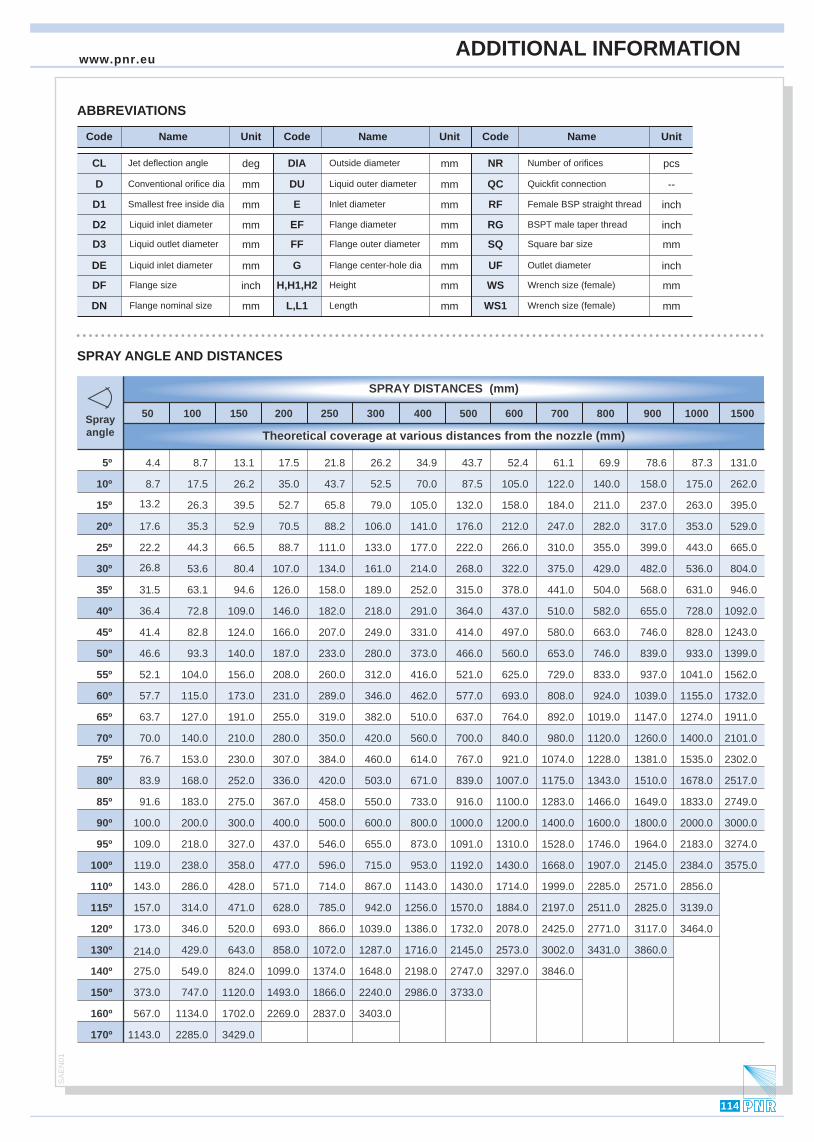
50 100 150 200 250 300 400 600 800 1000 1500
5º 8.7 17.5 21.8 26.2 34.9 43.7 52.4 61.1 78.6 87.3 131.0
10º 17.5 35.0 43.7 52.5 70.0 87.5 105.0 122.0 140.0 158.0 175.0 262.0
15º 26.3 39.5 52.7 65.8 79.0 105.0 132.0 158.0 184.0 211.0 237.0 263.0 395.0
20º 35.3 52.9 70.5 88.2 106.0 141.0 176.0 212.0 247.0 282.0 317.0 353.0 529.0
25º 44.3 66.5 88.7 111.0 133.0 177.0 222.0 266.0 310.0 355.0 399.0 443.0 665.0
30º 53.6 80.4 107.0 134.0 161.0 214.0 268.0 322.0 375.0 429.0 482.0 536.0 804.0
35º 63.1 94.6 126.0 158.0 189.0 252.0 315.0 378.0 441.0 504.0 568.0 631.0 946.0
40º 72.8 109.0 146.0 182.0 218.0 291.0 364.0 437.0 510.0 582.0 655.0 728.0 1092.0
45º 82.8 124.0 166.0 207.0 249.0 331.0 414.0 497.0 580.0 663.0 746.0 828.0 1243.0
50º 93.3 140.0 187.0 233.0 280.0 373.0 466.0 560.0 653.0 746.0 839.0 933.0 1399.0
55º 104.0 156.0 208.0 260.0 312.0 416.0 521.0 625.0 729.0 833.0 937.0 1041.0 1562.0
60º 115.0 173.0 231.0 289.0 346.0 462.0 577.0 693.0 808.0 924.0 1039.0 1155.0 1732.0
65º 127.0 191.0 255.0 319.0 382.0 510.0 637.0 764.0 892.0 1019.0 1147.0 1274.0 1911.0
70º 140.0 210.0 280.0 350.0 420.0 560.0 700.0 840.0 980.0 1120.0 1260.0 1400.0 2101.0
75º 153.0 230.0 307.0 384.0 460.0 614.0 767.0 921.0 1074.0 1228.0 1381.0 1535.0 2302.0
80º 168.0 252.0 336.0 420.0 503.0 671.0 839.0 1007.0 1175.0 1343.0 1510.0 1678.0 2517.0
85º 183.0 275.0 367.0 458.0 550.0 733.0 916.0 1100.0 1283.0 1466.0 1649.0 1833.0 2749.0
90º 200.0 300.0 400.0 500.0 600.0 800.0 1000.0 1200.0 1400.0 1600.0 1800.0 2000.0 3000.0
95º 218.0 327.0 437.0 546.0 655.0 873.0 1091.0 1310.0 1528.0 1746.0 1964.0 2183.0 3274.0
100º 119.0 238.0 358.0 477.0 596.0 715.0 953.0 1192.0 1430.0 1668.0 1907.0 2145.0 2384.0 3575.0
110º 286.0 428.0 571.0 714.0 867.0 1143.0 1430.0 1714.0 1999.0 2285.0 2571.0 2856.0
115º 314.0 471.0 628.0 785.0 942.0 1256.0 1570.0 1884.0 2197.0 2511.0 2825.0 3139.0
120º 346.0 520.0 693.0 866.0 1039.0 1386.0 1732.0 2078.0 2425.0 2771.0 3117.0 3464.0
130º 429.0 643.0 858.0 1072.0 1287.0 1716.0 2145.0 2573.0 3002.0 3431.0 3860.0
140º 549.0 824.0 1099.0 1374.0 1648.0 2198.0 2747.0 3297.0 3846.0
150º 747.0 1120.0 1493.0 1866.0 2240.0 2986.0 3733.0
160º 1134.0 1702.0 2269.0 2837.0 3403.0
170º 1143.0 2285.0 3429.0
4.4
8.7
Sprayangle
SPRAY DISTANCES (mm)
Theoretical coverage at various distances from the nozzle (mm)
13.2
17.6
22.2
26.8
31.5
36.4
41.4
46.6
52.1
57.7
63.7
70.0
76.7
83.9
91.6
100.0
109.0
143.0
157.0
173.0
214.0
275.0
373.0
567.0
13.1
26.2
69.9
500 700 900
ABBREVIATIONS
SPRAY ANGLE AND DISTANCES
Name NameCode
NR
RF
RG
UF
WS
WS1
Code
E
EF
G
H,H1,H2
L,L1
Unit
mm
mm
mm
mm
inch
mm
mm
deg
NameCode
CL
D
D1
D2
D3
DF
DN
DE
Jet deflection angle
Conventional orifice dia
Smallest free inside dia
Liquid inlet diameter
Liquid outlet diameter
Liquid inlet diameter
mmDU Liquid outer diameter
mmFF Flange outer diameter mmSQ Square bar size
--QC Quickfit connection
Flange size
Flange nominal size
mmDIA Outside diameter
Unit
mm
mm
mm
mm
mm
Inlet diameter
Flange diameter
Flange center-hole dia
Height
Number of orifices
Unit
inch
inch
inch
mm
mm
pcs
Female BSP straight thread
BSPT male taper thread
Outlet diameter
Wrench size (female)
Wrench size (female)Length
ADDITIONAL INFORMATION
114
www.pnr.euS
AE
N01
Related Documents


