TECHNICAL DATA January 27, 2012 Firecycle 400a UPGRADE INSTRUCTIONS FIRECYCLE ® II TO FIRECYCLE ® III MULTI-CYCLE The Viking Corporation, 210 N Industrial Park Drive, Hastings MI 49058 Telephone: 269-945-9501 Technical Services: 877-384-5464 Fax: 269-818-1680 Email: [email protected] 1. DESCRIPTION The Firecycle ® ll system is a single interlocked preaction system that has the ability to cycle on and off until the fire is potentially out. Firecycle ® ll is an FM Approved system, but is no longer offered by The Viking Corporation. The system is being phased out due to integral components of the system, namely the mother board of the release control panel, no longer being manufactured. An upgrade option for Firecycle ® ll to Firecycle ® III Multi-Cycle single interlocked preaction system is available. The cycling function for Firecycle ® III Multi-Cycle is the same as for Firecycle ® ll but utilizes recent technology and does not require the large power supply of Firecycle ® ll. 2. TECHNICAL DATA WARNING!: FIRECYCLE II SYSTEMS MAY ONLY BE UPGRADED TO A FIRECYCLE III SINGLE INTERLOCK PREACTION SYS- TEM. UPGRADING TO A DOUBLE INTERLOCK SYSTEM IS NOT PERMITTED. NOTE: FIRECYCLE ® II DETECTORS AND DETECTOR CABLE ARE COMPATIBLE WITH THE FIRECYCLE ® III MULTI-CYCLE RELEASE CONTROL PANEL AND DO NOT REQUIRE REPLACEMENT FOR UPGRADE PURPOSES. 3. REMOVING FIRECYCLE ® II FROM SERVICE: NOTE: ALL AUXILIARY OR CENTRAL STATION ALARM NOTIFICATION FACILITIES SHOULD BE NOTIFIED THAT MAINTE- NANCE IS BEING PERFORMED ON THE SYSTEM. Close the main control valve. Turn off the power supply to the Firecycle ® ll Release Control Panel. Silence local alarm. Remove power and neutral wires from L1 and L2 in the Firecycle ® ll Release Control Panel and the ground wire and terminate correctly. (This may require the aid of a qualified electrician) Remove battery power supply leads from Model A-1 Battery Charger, landing contacts B+ and B-. (Removing this power supply will cause the solenoid valves in the valve trim box to open and drain priming water pressure out of the valve trim piping) Remove Firecycle ® detector cable leads from landing contacts 15 and 16 in the Firecycle ® ll Release Control Panel. Remaining interface wiring between panels and alarms can now be removed. CAUTION: Confirm outside interfacing alarms have been disabled. Turn off air supply to system. Open system drain valve. Remove valve trim to ¼” priming valve. 1. 2. 3. 4. 5. 6. 7. 8. 9. 10. Replaces page 400a-f, dated March 6, 2009. (Revised Model VFR-400 Release Control Panel part number.) Form No. F_062200 Viking Technical Data may be found on The Viking Corporation’s Web site at http://www.vikinggroupinc.com. The Web site may include a more recent edition of this Technical Data Page. Table 1 - Components Required to Upgrade to Firecycle ® III Multi-Cycle System Qty. Description Part Number 1 VFR-400 Release Control Panel 14152-1 2 18 amp hour batteries 09867 1 Battery Cabinet 09866 1 Firecycle ® III Multi-Cycle Single Interlocked Preaction System Valve Trimpac 13801E-1 1 Drain Package for Trimpac 1-1/2” - 11894-1 2” - 11894-2 2-1/2” & 3” - 11894-3 4”, 6” & 8” - 11894-4 Any system maintenance that involves placing a control valve or detection system out of service will impair the fire protection capa- bilities of that system. Prior to proceeding, appropriate impairment procedures per NFPA 25 shall be followed with the notification of all Authorities Having Jurisdiction. Consideration should be given to employment of a fire patrol in the affected areas. Failure to follow these instructions could cause improper system operation, resulting in serious personal injury and/or property damage.

Welcome message from author
This document is posted to help you gain knowledge. Please leave a comment to let me know what you think about it! Share it to your friends and learn new things together.
Transcript
TECHNICAL DATA
January 27, 2012 Firecycle 400a
upgrADE INSTruCTIONSFIrECYCLE® II TO
FIrECYCLE® III MuLTI-CYCLE
The Viking Corporation, 210 N Industrial park Drive, Hastings MI 49058Telephone: 269-945-9501 Technical Services: 877-384-5464 Fax: 269-818-1680 Email: [email protected]. DESCrIpTION
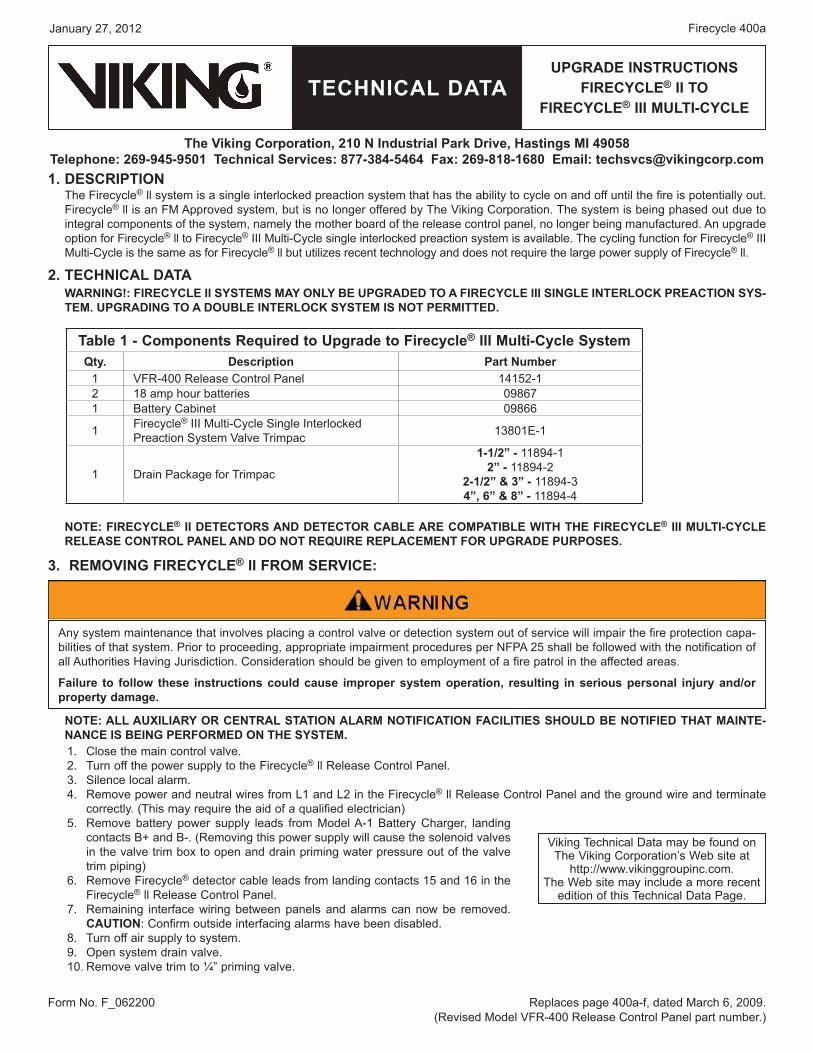
The Firecycle® ll system is a single interlocked preaction system that has the ability to cycle on and off until the fire is potentially out. Firecycle® ll is an FM Approved system, but is no longer offered by The Viking Corporation. The system is being phased out due to integral components of the system, namely the mother board of the release control panel, no longer being manufactured. An upgrade option for Firecycle® ll to Firecycle® III Multi-Cycle single interlocked preaction system is available. The cycling function for Firecycle® III Multi-Cycle is the same as for Firecycle® ll but utilizes recent technology and does not require the large power supply of Firecycle® ll.
2. TECHNICAL DATAWArNINg!: FIrECYCLE II SYSTEMS MAY ONLY bE upgrADED TO A FIrECYCLE III SINgLE INTErLOCk prEACTION SYS-TEM. upgrADINg TO A DOubLE INTErLOCk SYSTEM IS NOT pErMITTED.
NOTE: FIrECYCLE® II DETECTOrS AND DETECTOr CAbLE ArE COMpATIbLE WITH THE FIrECYCLE® III MuLTI-CYCLE rELEASE CONTrOL pANEL AND DO NOT rEquIrE rEpLACEMENT FOr upgrADE purpOSES.
3. rEMOVINg FIrECYCLE® II FrOM SErVICE:
NOTE: ALL AuxILIArY Or CENTrAL STATION ALArM NOTIFICATION FACILITIES SHOuLD bE NOTIFIED THAT MAINTE-NANCE IS bEINg pErFOrMED ON THE SYSTEM.
Close the main control valve. Turn off the power supply to the Firecycle® ll Release Control Panel. Silence local alarm. Remove power and neutral wires from L1 and L2 in the Firecycle® ll Release Control Panel and the ground wire and terminate correctly. (This may require the aid of a qualified electrician)Remove battery power supply leads from Model A-1 Battery Charger, landing contacts B+ and B-. (Removing this power supply will cause the solenoid valves in the valve trim box to open and drain priming water pressure out of the valve trim piping)Remove Firecycle® detector cable leads from landing contacts 15 and 16 in the Firecycle® ll Release Control Panel. Remaining interface wiring between panels and alarms can now be removed. CAuTION: Confirm outside interfacing alarms have been disabled.Turn off air supply to system. Open system drain valve. Remove valve trim to ¼” priming valve.
1.2.3.4.
5.
6.
7.
8.9.10.
Replaces page 400a-f, dated March 6, 2009.(Revised Model VFR-400 Release Control Panel part number.)
Form No. F_062200
Viking Technical Data may be found on The Viking Corporation’s Web site at
http://www.vikinggroupinc.com.The Web site may include a more recent
edition of this Technical Data Page.
Table 1 - Components required to upgrade to Firecycle® III Multi-Cycle Systemqty. Description part Number
1 VFR-400 Release Control Panel 14152-12 18 amp hour batteries 098671 Battery Cabinet 09866
1 Firecycle® III Multi-Cycle Single Interlocked Preaction System Valve Trimpac 13801E-1
1 Drain Package for Trimpac
1-1/2” - 11894-1 2” - 11894-2
2-1/2” & 3” - 11894-3 4”, 6” & 8” - 11894-4
Any system maintenance that involves placing a control valve or detection system out of service will impair the fire protection capa-bilities of that system. Prior to proceeding, appropriate impairment procedures per NFPA 25 shall be followed with the notification of all Authorities Having Jurisdiction. Consideration should be given to employment of a fire patrol in the affected areas.
Failure to follow these instructions could cause improper system operation, resulting in serious personal injury and/or property damage.

TECHNICAL DATA
January 27, 2012Firecycle 400b
upgrADE INSTruCTIONSFIrECYCLE® II TO
FIrECYCLE® III MuLTI-CYCLE
The Viking Corporation, 210 N Industrial park Drive, Hastings MI 49058Telephone: 269-945-9501 Technical Services: 877-384-5464 Fax: 269-818-1680 Email: [email protected] 4. INSTALLATION OF FIrECYCLE® III MuLTI-CYCLE upgrADE COMpONENTS
Mount the Model E-1 Trimpac in an appropriate location near the riser. Refer to Technical Data Page 253a-s.Disconect all wiring tied into the Firecycle® II Release Control Panel.Remove Firecycle® ll Multi-Cycle Release Control Panel, Valve Trim Box, Batteries, Battery Box, Battery Charger. Install the Model VFR-400 Release Control Panel. Wire the VFR-400 panel per the wiring diagragm for program #6. The wiring diagram is found in the VFR-400 Installation, Operation and Instruction Manual.Once last connection is made, move Program switch down.Press the FUNCTION (bottom) button until the display reads “PASSWORD = 000”.To enter a password, press the SELECT button until the proper number is displayed above the ^ symbol, then press the SET button to move to the next digit. After entering the third number the display will change. (All panels are shipped with a 000 password.)Press the FUNCTION (bottom) button until the display reads “PROGRAM #6”.Press the SELECT button until the display reads “PROGRAM #6”.Press the SET button.Set the soak timer to the desired duration. The panel is completely programmed except for the custom banner and zone messages. Move the program switch back up.
5. pLACE FIrECYCLE® III MuLTI-CYCLE prE-ACTION SYSTEM IN SErVICEVerify that the VFR-400 Release Control Panel, Detector Circuits, and Detectors have been properly installed and energized ac-cording to instructions provided in Viking Technical Data.Verify that the system has been properly drained. (When the plunger is depressed on drip check, no water should flow) System Drain should be open. Verify that the emergency release is closed. Verify that the system main water control valve is closed. Verify that the system water supply piping is pressurized up to the closed system main water supply control valve and the priming line is pressurized up to the closed priming valve.Apply supervisory air pressure to 35 psi (2.4 bar) (55 psi (3.8 bar) for systems with greater than 175 psi (12 bar) water pressure) on system piping.Open priming valve. Prime pressure should rise on priming pressure gauge.Press SYSTEM RESET on the VFR-400 Release Control Panel. Open the flow test valve.Partially open the water supply control valve. Close the flow test valve. Fully open the water supply control valve. Press SYSTEM RESET on the VFR-400 Release Control Panel.
6. TEST FIrECYCLE® III MuLTI-CYCLE SYSTEMTest the system according to the instructions found in the Technical Data for Model E-1 Trimpac and the Model VFR-400 Release Control Panel.
1.2.3.4.5.
6.7.8.
9.10.11.12.13.
1.
2.
3.4.
5.
6.7.8.9.10.
1. required ComponentsA. Flow Control ValveB. Trim Piping and Components
Rubber Seated Check ValveControl ValveFirecycle® Control PanelFirecycle® Trim BoxBattery ChargerBatteriesFirecycle® Detector(s)Firecycle® Detector CableMain Drain ValveIntermediate Drain ValvePriming ValvePosition IndicatorStrainerElectric Bell
C. Air SupplyAcceptable Primary or Maintenance Air
2. Optional EquipmentPressure SwitchWater Motor AlarmAlarm Test ValveAlarm Shut-off Valve
1.2.3.4.5.6.7.8.9.10.11.12.13.14.
15.
16.17.18.19.
Figure 1 - Firecycle® II System Components

TECHNICAL DATA
January 27, 2012 Firecycle 400c
upgrADE INSTruCTIONSFIrECYCLE® II TO
FIrECYCLE® III MuLTI-CYCLE
The Viking Corporation, 210 N Industrial park Drive, Hastings MI 49058Telephone: 269-945-9501 Technical Services: 877-384-5464 Fax: 269-818-1680 Email: [email protected]
Figure 2 - Firecycle® II Control panel Wiring Diagram

TECHNICAL DATA
January 27, 2012Firecycle 400d
upgrADE INSTruCTIONSFIrECYCLE® II TO
FIrECYCLE® III MuLTI-CYCLE
The Viking Corporation, 210 N Industrial park Drive, Hastings MI 49058Telephone: 269-945-9501 Technical Services: 877-384-5464 Fax: 269-818-1680 Email: [email protected]
Component Description part Numbers Corresponding Data pages
ASystem Valve
A.1 Flow Control Valve Various 500 through 508
bTrimpac® 13801E-1 253a-s
B.1 - B.17 Trimpac® Components Refer to Figure 10
C
Trimpac® Drain packageC.1 Auxiliary Drain Valve (NC) 1-1/2” -
2” - 2-1/2” & 3” - 4”, 6” & 8” -
11894-111894-211894-311894-4
253a-sC.2 Drip Check ValveC.3 Drain CupC.4 Folw Test Valve (NC)
Driser
D.1 Water Supply Control Valve - -
E
Check ValveE.1 1-1/2” & 2” - Model L-1 or M-1 Check Valve
3” - 8” - Easy Riser® Check Valve Various 804a-d815a-f
E.2 Check Valve Trim Various
F
release SystemF.1 Model VFR-400 Release Control Panel 14152-1 290a-h
F.2 Firecycle® DetectorsFirecycle® III Various 417a-c
Firecycle® III-OH Various 429a-d
F.3 Detector Cables
Aluminum Clad Cable 04632A 419a-b
FPL Cable 16 Gauge - 0995418 Gauge - 11988 419 d-g
Table 2 - Trimpac® System Componentsrefer to Figure 3 for component identification
NOTE: When viewing this data page online, blue text represents hyperlinks and will open the desired data page when clicked.
Legend for Figure 3

TECHNICAL DATA
January 27, 2012 Firecycle 400e
upgrADE INSTruCTIONSFIrECYCLE® II TO
FIrECYCLE® III MuLTI-CYCLE
The Viking Corporation, 210 N Industrial park Drive, Hastings MI 49058Telephone: 269-945-9501 Technical Services: 877-384-5464 Fax: 269-818-1680 Email: [email protected]
Figure 3 - Firecycle® III Multi-Cycle Single Interlocked preaction SystemNote: The 6” angle style valve is shown. refer to data page 253a-r for other valve sizes.

TECHNICAL DATA
January 27, 2012Firecycle 400f
upgrADE INSTruCTIONSFIrECYCLE® II TO
FIrECYCLE® III MuLTI-CYCLE
The Viking Corporation, 210 N Industrial park Drive, Hastings MI 49058Telephone: 269-945-9501 Technical Services: 877-384-5464 Fax: 269-818-1680 Email: [email protected]
Figure 4 - Trimpac® Components
Note: Emergency release (b.1) is closed when the handle is in line with the pipe. This allows the door to close when the valve is in the normal position.
Replaces page 400a-f, dated March 6, 2009.(Revised Model VFR-400 Release Control Panel part number.)
Form No. F_062200
Related Documents