Flexible AC Transmission System Overview

Welcome message from author
This document is posted to help you gain knowledge. Please leave a comment to let me know what you think about it! Share it to your friends and learn new things together.
Transcript
Flexible AC Transmission System Overview
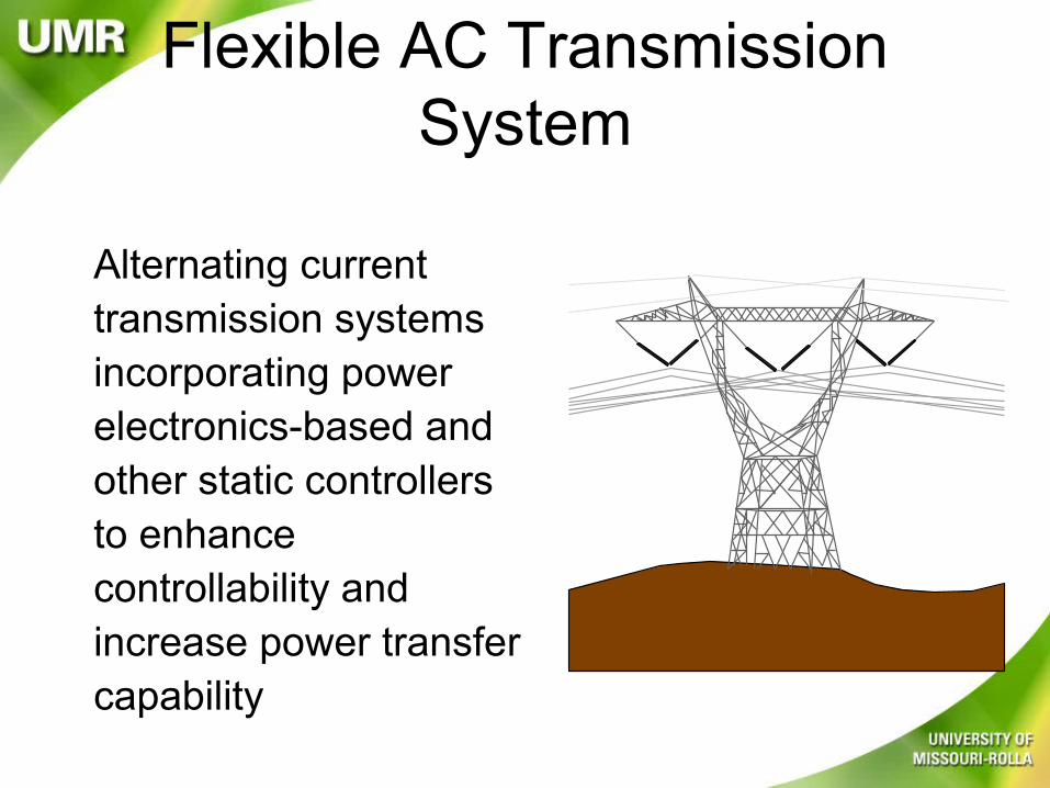
Flexible AC Transmission System
Alternating current transmission systems incorporating power electronics-based and other static controllers to enhance controllability and increase power transfer capability
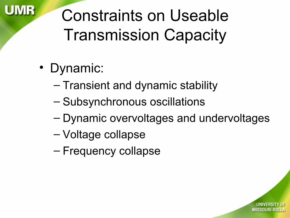
Constraints on Useable Transmission Capacity
• Dynamic:– Transient and dynamic stability
– Subsynchronous oscillations– Dynamic overvoltages and undervoltages– Voltage collapse– Frequency collapse
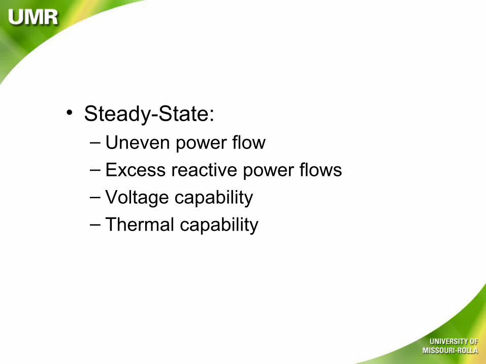
• Steady-State:– Uneven power flow
– Excess reactive power flows– Voltage capability– Thermal capability
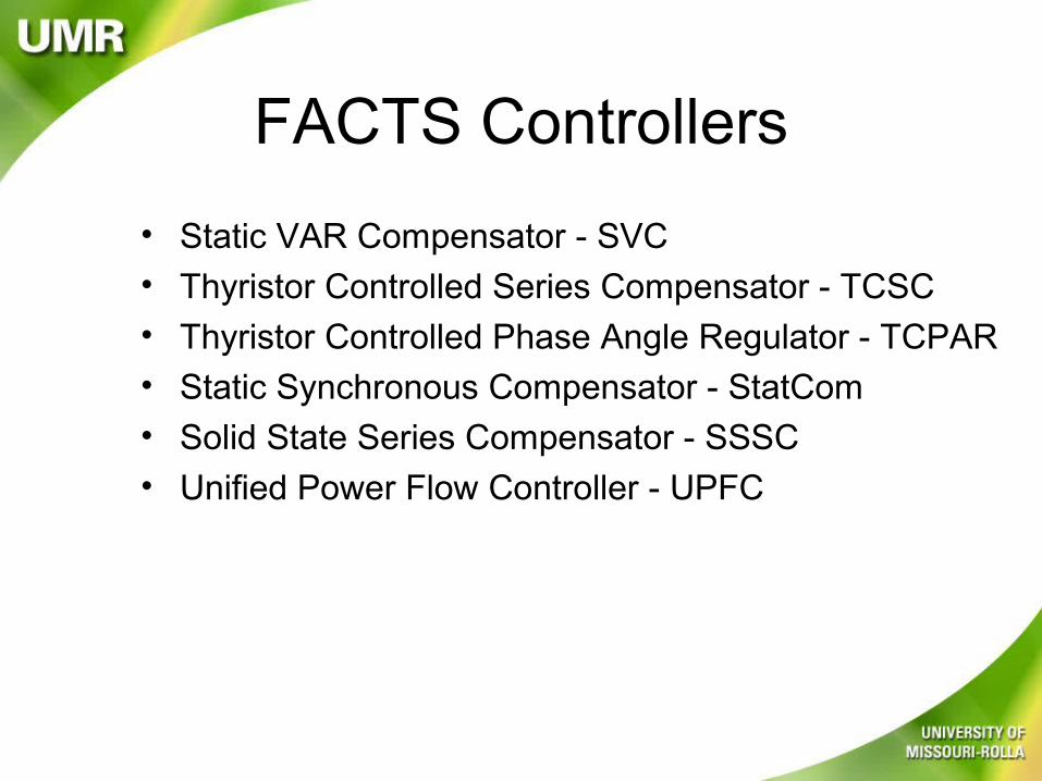
FACTS Controllers
• Static VAR Compensator - SVC• Thyristor Controlled Series Compensator - TCSC• Thyristor Controlled Phase Angle Regulator - TCPAR• Static Synchronous Compensator - StatCom
• Solid State Series Compensator - SSSC
• Unified Power Flow Controller - UPFC
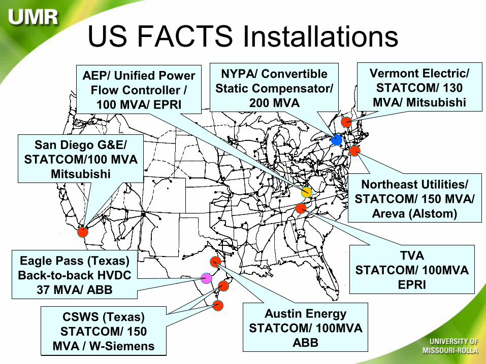
US FACTS Installations
San Diego G&E/STATCOM/100 MVA
Mitsubishi
Eagle Pass (Texas)Back-to-back HVDC
37 MVA/ ABB
CSWS (Texas)STATCOM/ 150
MVA / W-Siemens
Austin EnergySTATCOM/ 100MVA
ABB
AEP/ Unified Power Flow Controller /100 MVA/ EPRI
TVASTATCOM/ 100MVA
EPRI
Northeast Utilities/ STATCOM/ 150 MVA/
Areva (Alstom)
NYPA/ Convertible Static Compensator/
200 MVA
Vermont Electric/ STATCOM/ 130
MVA/ Mitsubishi
• Power transfer between areas can be affected by adjusting the net series impedance.
• Transmission line capability can be increased by installing a series capacitor which reduces the net series impedance.
Power Flow Control
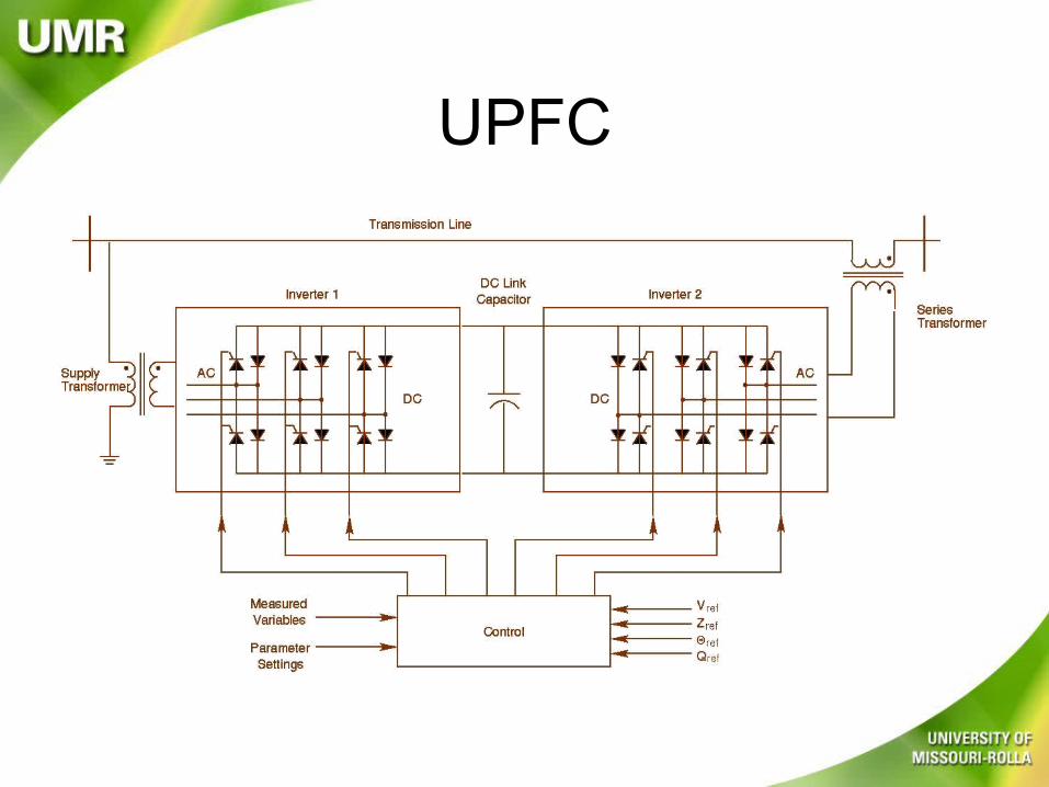
UPFC

UPFC
• may control voltage, impedance, and angle• impacts active and reactive power flow in line

Basic Operation
UPFC Capabilities
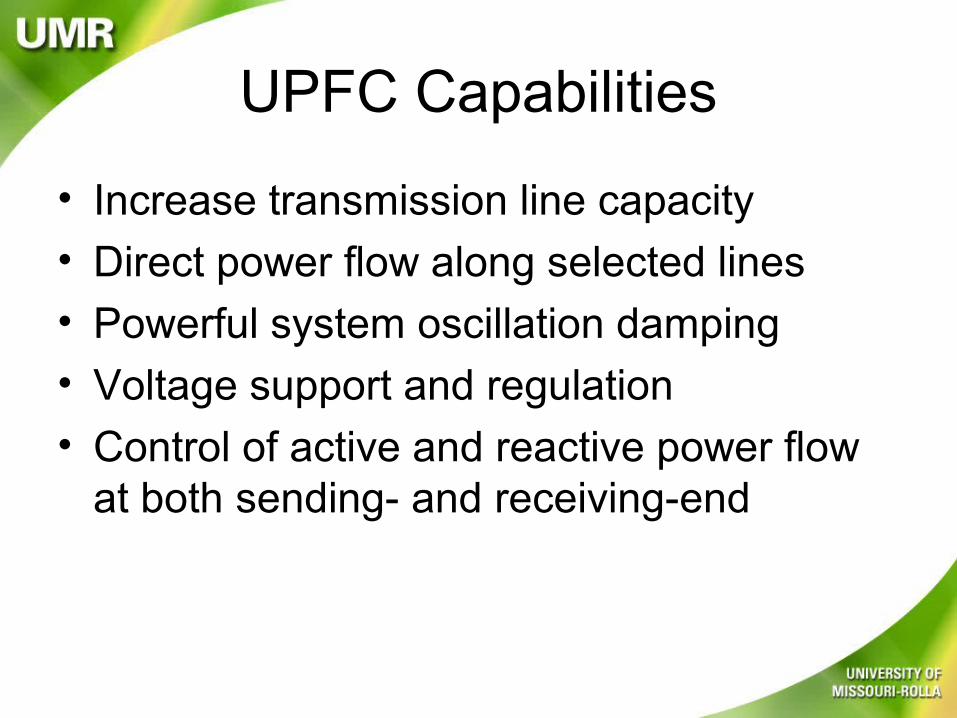
• Increase transmission line capacity
• Direct power flow along selected lines
• Powerful system oscillation damping
• Voltage support and regulation
• Control of active and reactive power flow at both sending- and receiving-end
Operation
• Reactive power is generated or absorbed by the shunt inverter to control bus voltage
• Reactive power is generated or absorbed by the series inverter to control the real and/or reactive power flow on the transmission line
Cont’d
• A portion of the real power flow on the transmission line is drawn from the bus by the shunt inverter to charge the DC capacitor.
• Real power is inserted into the line through the series inverter.
jXSV RV
SRP
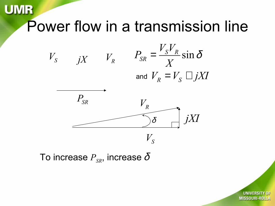
sinS RSR
V VP
Xδ=
Power flow in a transmission line
δTo increase PSR, increase
and R SV V jXI= +
jXI
SV
RV
δ
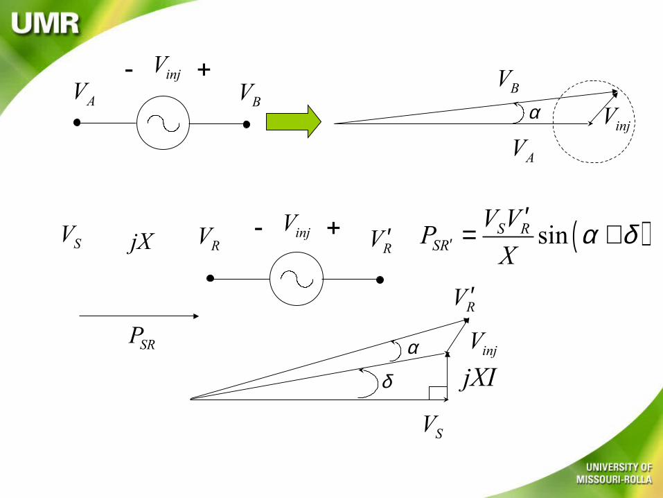
AV BVinjV- +
AVinjV
BVα
jXSV RV
SRP
RV ′injV- + ( )sinS RSR
V VP
Xα δ′
′= +
jXIinjV
SV
RV ′
δ
α

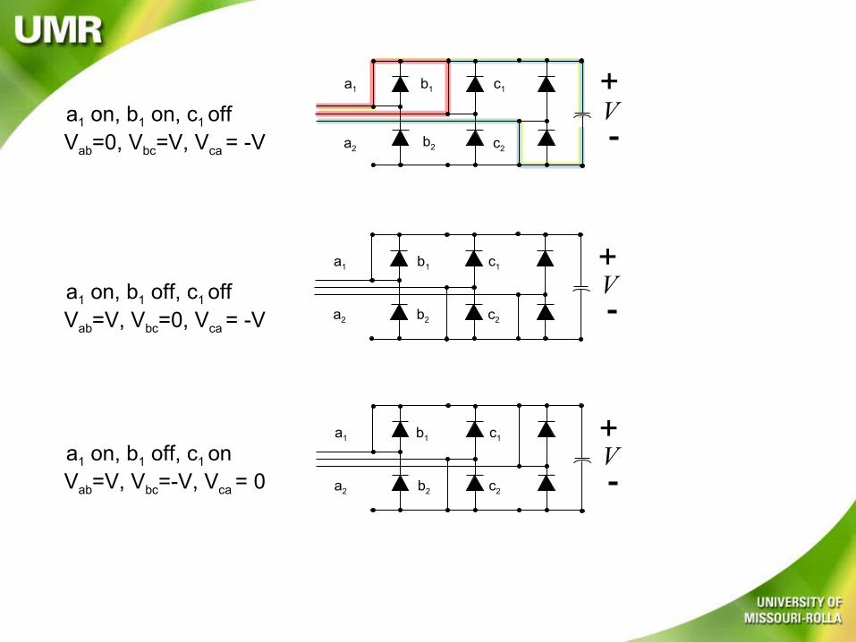
How is Vinj created?
V+b1
a2
a1
b2
c1
c2
V+b1
a2
a1
b2
c1
c2
a1 on, b1 on, c1 offVab=0, Vbc=V, Vca = -V
a1 on, b1 off, c1 offVab=V, Vbc=0, Vca = -V
V+a1 b1 c1
c2b2a2
V+a1 b1 c1
c2b2a2
a1 on, b1 off, c1 onVab=V, Vbc=-V, Vca = 0
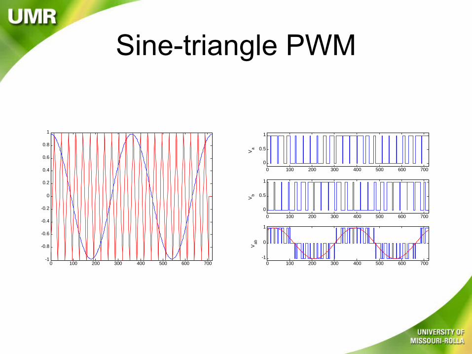
Sine-triangle PWM
0 100 200 300 400 500 600 700-1
-0.8
-0.6
-0.4
-0.2
0
0.2
0.4
0.6
0.8
1
0 100 200 300 400 500 600 700
0
0.5
1
Va
0 100 200 300 400 500 600 700
0
0.5
1
Vb
0 100 200 300 400 500 600 700-1
0
1
Vab
Related Documents