Updated status of the undulator-based ILC positron source S. Riemann 1* , P. Sievers 2 , G. Moortgat-Pick 3 , A. Ushakov 3 1 Deutsches Elektronen-Synchrotron (DESY), Platanenallee 6, D-15738 Zeuthen 2 CERN, CH-1211 Geneva 23, Switzerland 3 University of Hamburg, Luruper Chaussee 149, D-22761 Hamburg Abstract The design of the positron source for the International Linear Collider (ILC) is still under discussion. The baseline design plans to use the high-energy electron beam for the positron production before it goes to the IP. The electrons pass a long helical undulator and generate an intense circularly polarized photon beam which hits a thin conversion target to produce e + e - pairs. The resulting positron beam is longitudinally polarized which provides an important benefit for precision physics analyses at the ILC. In this paper the status of the positron target design studies is presented. Focus is the positron yield for center-of-mass energies of 250 GeV and also the Z peak. Possibilities to improve the positron collection system and thus to increase the positron yield are discussed. . * corresponding author, [email protected] 1 arXiv:2002.10919v1 [physics.acc-ph] 23 Feb 2020

Welcome message from author
This document is posted to help you gain knowledge. Please leave a comment to let me know what you think about it! Share it to your friends and learn new things together.
Transcript

Updated status of the undulator-based ILC positronsource
S. Riemann1∗, P. Sievers2, G. Moortgat-Pick3, A. Ushakov3
1Deutsches Elektronen-Synchrotron (DESY), Platanenallee 6, D-15738 Zeuthen2CERN, CH-1211 Geneva 23, Switzerland
3University of Hamburg, Luruper Chaussee 149, D-22761 Hamburg
Abstract
The design of the positron source for the International Linear Collider (ILC) isstill under discussion. The baseline design plans to use the high-energy electronbeam for the positron production before it goes to the IP. The electrons pass a longhelical undulator and generate an intense circularly polarized photon beam whichhits a thin conversion target to produce e+e− pairs. The resulting positron beam islongitudinally polarized which provides an important benefit for precision physicsanalyses at the ILC. In this paper the status of the positron target design studiesis presented. Focus is the positron yield for center-of-mass energies of 250 GeV andalso the Z peak. Possibilities to improve the positron collection system and thus toincrease the positron yield are discussed.
.
∗corresponding author, [email protected]
1
arX
iv:2
002.
1091
9v1
[ph
ysic
s.ac
c-ph
] 2
3 Fe
b 20
20

1 Introduction
The discussion on the positron production scheme for a high-energy linear e+e− collideris ongoing: Two schemes are under consideration: The baseline scheme using a helicalundulator passed by the high-energy electron beam to generate an intense photon beamfor the positron production in a thin target, and the scheme based on the use of aseparate electron beam to create e+e− pairs in a thick target. The efficiency of positronproduction in a conversion target together with the capture acceleration of the positronsis low, so in both cases it is a challenge to generate the 1.3×10¹⁴ positrons per second thatare required at the ILC collision point (nominal luminosity). However, using a helicalundulator allows to produce a circularly polarized photon beam for the generation of alongitudinally polarized positron beam. A high-energy e+e− collider with both beamspolarized broadens substantially the physics potential and has been chosen as baselineoption for the ILC positron source [1–3].
In this paper the status of the studies for the undulator based source is updated; itcontinues the results given in references [4] and [5]. Details on the electron driven sourcecan be found in references [6, 7].
This paper is organized as follows: The basic parameters of the undulator source aregiven in section 2. Due to the low efficiency of the e+e− pair production and the requiredhigh luminosity, the heat load in the target and hence the cooling are important issues.To stand the heat load the positron target must be moved and is designed as rotatingwheel. The basic items are discussed in detail in references [4] and [5] and summarizedin section 2. The positron yield depends strongly on the design of the optical matchingdevice (OMD) located directly behind the conversion target. In section 3 the influenceof the magnetic field on the positron yield is discussed. It is well known, that a highmagnetic field at the target increases substantially the positron yield. Possible optionsto realize the magnetic field required for high positron yield as well as the resultingeddy currents in the spinning target which could increase the heat load are reviewed insection 4. The necessary R&D work is shortly outlined in section 5. Section 6 emphasizesthe benefit of a polarized positron beam for the ILC project. A short summary is givenin section 7.
2

2 The undulator-based ILC positron source
The ILC positron source is located at the end of the main linac. It consists of the helicalundulator with maximum active length of 231 m to generate the photon beam, the thinconversion target made of Ti6Al4V, the optical matching device and the capture optics,acceleration, energy and bunch compression, spin rotation and spin flipper as shown infigure 1 and references [1–3, 8]. Goal is a positron yield of 1.5 e+/e− at the damping
Figure 1: Sketch of the undulator-based ILC positron source.
ring. Since the photon energy and yield, and hence the positron yield depend stronglyon the electron energy, the source performance has to be studied and optimized for eachcentre-of-mass energy.
2.1 The helical undulator
A superconducting helical undulator is used to generate the circularly polarized photonbeam. A prototype was manufactured and tested in UK [9]. It consists of two 1.75 mlong undulator modules inserted in a 4 m long cryomodule. The undulator period isλu = 11.5 mm and the maximum B field is 0.86 T corresponding to a value K = 0.92. Asdescribed in the TDR, with 132 undulator modules (66 cryomodules) an active undulatorlength of 231 m is reached. Every 3 cryomodules quadrupoles are foreseen so that theundulator system reaches a total length of 320 m. The given undulator period, λu, andthe maximum field on axis, B0, define together with te electron beam energy the possibleparameter range for the positron source: The undulator K value is K ∝ λuB0. Theefficiency of positron generation in the target depends on the pair production cross sectionand hence on the photon energy. The cut-off for the first harmonic is related to theelectron energy Ee, K and λu by
E1γ ∝Ee
λu(1 +K2), (1)
i.e. lower K values increase the photon energy. The number of photons created perundulator length is
Nγ ∝K2
λu(1 +K2), (2)
implying that low K values result in less photons. For an electron beam energy 125 GeV ahigh K value and the full active length of the undulator are necessary to get the required
3

number of positrons.Also the beam spot size on the target depends on the opening angle of the photon beam,
θγ ∝√
1 +K2
γ, (3)
and it is very small even at a large distance from the undulator. This defines the designfor the conversion target; during the 0.73 ms (baseline) up to 1 ms long bunchtrain over-heating must be prevented to avoid serious damage. Details are discussed in section 2.2.
2.2 The conversion target
The narrow photon beam causes a high peak energy deposition density (PEDD) in thetarget material. To prevent overheating during one ILC pulse, the target is designed aswheel of 1 m diameter spinning with 100 m/s circumferential speed to distribute the beamload over about 7-10 cm. The target thickness should be optimized regardig the energy ofthe electron beam; for ILC250 a thickness of 7 mm Ti6Al4V is recommended (≈ 0.2 X0).Downstream the target, an optical matching device (OMD) collects the positrons usinga high B field which goes adiabatically down to 0.5 T at the accelerating structures. Toachieve the required positron yield and to protect the accelerating structures the targetwheel rotates in vacuum. The PEDD and the average power deposited in the target aswell as the positron yield vary for different Ecm; they also depend on the distance betweentarget and undulator. In previous studies the interplay of the source parameters has beenstudied for different centre-of-mass energies [4,5,10–13]. Most of these studies assumed apulsed flux concentrator (FC) as optical matching device (OMD). A promising prototypestudy for the FC was performed by LLNL [14]. However, detailed studies identified someweak items of this design: The B field distribution along z cannot be kept stable overthe long bunch train duration. So the luminosity would vary during the pulse which isnot desired. Further, the particle shower downstream the target causes a high load atthe inner part of the flux concentrator front side, which is at least for ILC250 beyondthe recommended material load level [13]. This is mainly caused by the larger openingangle of the photon beam and the wider distribution of the shower particles downstreamthe target at ILC250. To resolve this problem, the drift space between the middle ofundulator and the target was reduced to 401 m. In addition, a quarter wave transformeris suggested as OMD since it has a larger aperture. Further details can be found inreferences [13, 15]. An alternative could be a pused solenoid; this option is disussed insection 3.
Another important issue is the cooling of the target spinning in vacuum. The pre-viously contemplated water cooling was given up and replaced by cooling by thermalradiation.
Table 1 presents an overview of the relevant parameters for the studies with focus onan 125 GeV electron beam for positron production.
The positron yield was simulated for a flux concentrator and a quarter wave trans-former (QWT). In both cases the positron beam polarization is 30%. However, thepositron yield depends strongly on the magnetic field assumed for the simulations. Thenumbers in table 1 given for the QWT suppose an optimized shape of the B field: At thetarget exit the B field is zero. It achieves the maximum value of 1.04 T at a distance of7.6 mm downstream the target. However, the design given in reference [16] corresponds toa realistic design and has the maximum B field at a distance of about 3.5 cm downstream
4

FC QWTelectron beam energy GeV 126.5undulator active length m 231space from middle of undulator to target m 401undulator K 0.85 0.92photon yield per m undulator γ/(e− m) 1.70 1.95photon yield γ/e− 392.7 450.4photon energy (1st harmonic) MeV 7.7 7.2average photon energy MeV 7.5 7.6average photon beam power kW 62.6 72.2average power deposited in target kW 1.94 2.2rms photon beam spot size on target (σ) mm 1.2 1.45PEDD in target per pulse (100 m/s) J/g 61.0 59.8
Table 1: Summary of the source performance parameters for ILC250 with 1312 bunches
per pulse and two different undulator K values. The pulse repetition rate is 5Hz. The
numbers are shown for a decelerating capture field. See also references [1–3,8, 11–13].
the target exit. So for the ideal case the design yield of ≈ 1.5e+/e− is almost achievedwhile with the realistic QWT the yield is less than but close to 1. More details are givenin section 3.
2.2.1 Temperature distribution in the target wheel
The average energy deposition in the ILC positron target is about 2−7 kW depending onthe drive beam energy in the undulator, the target thickness and the luminosity (nominalor high). For ILC250, the average energy deposition in the target is 2 kW.Since the initial investigations of the wheel, involving leak tight rotating vacuum sealsand water cooling showed major problems [14, 17], an alternative technical solution wasbrought up to ensure the heat radiation as well as the safe rotation of 2000 rpm bymagnetic bearings [18, 19]. This proposal is now considered as solution for the targetwheel design. The energy deposition of few kW can be extracted by radiation cooling ifthe radiating surface is large enough and the heat distributes fast enough from the areaof incident beam to a large radiating surface. The wheel spinning in vacuum radiates theheat to a stationary cooler opposite to the wheel surface. It is easy to keep the stationarycooler at room temperature by water cooling. But it is crucial for the design that the heatdistributes from the volume heated by the photon beam to a larger surface area. Thethermal conductivity of Ti6Al4V is low, λ = 0.068 W/(cm K) at room temperatures and0.126 W/(cm K) at 540C. The heat capacity is c = 0.58 J/(g K) at room temperatureand 0.126J/(g K) at 540C [20]. With the wheel rotation frequency of 2000rpm each partof the target rim is hit after 6-8 seconds but this time is not sufficient to distribute theheat load almost uniformly over a large area. The heat is accumulated in the rim and thehighest temperatures are located in a relatively small region around the beam path. Theaverage temperature distribution was calculated using the ANSYS software package [21]and is shown in figure 2 for one sector representative for the track of one bunch train.
The temperature depends substantially on the emissivity ε, of the surfaces. An op-timization of the emissivities by surface processing or coating is possible and should be
5

Figure 2: Average temperature distribution in the target shown for a sector correspondingto 1 pulse length (0.73 ms) at ILC250; the beam impinges on the target at r=50 cm. Theemissivities of target and cooler surface are 0.5 corresponding to an effective emissivityof ε = 0.33.
tested also under long-term irradiation conditions as expected at the ILC. Figure 3 showsthe radial temperature profile assuming different emissivities. In addition also the radiusof the wheel increased to enhance the surface for the T4 radiation. A rough estimate [4,5]shows that with a wheel radius of about 60 cm the average temperature could be de-creased by 100 K or even more. This is important since every 6-7 seconds the beam pulseincreases the temperature by approximately 60-100 K within about 50µs depending onthe required luminosity. The material must stand the cyclic load at elevated tempera-tures. Experimental tests were performed with the electron beam of the microtron inMainz (MAMI) to simulate the cyclic load as expected during ILC operation [22,23] anddemonstrated that the material is suited for this application.
The thermomechanical stress in a rotating target wheel disc is discussed in detail inreferences [4,5,10]. The results of the irradiation tests at MAMI and detailed simulationstudies with ANSYS showed that the expected load at the ILC positron target is belowthe material limits [4, 24]. However, for the final construction of the target wheel FEMdesign studies and systematic tests using a mock-up are necessary to ensure a long-termoperation without failure.
2.3 Engineering and Design Options for the Rotating Wheel
For the studies of the positron yield optimization, the temperature distribution and cool-ing principle a target wheel designed as full 1 m-diameter disc of 7mm thickness madeof Ti6Al4V was assumed. As illustrated in figure 3, the radial steady state temperaturein the wheel depends also on the radius. Due to the the heat conductivity in the targetmaterial and the T 4 dependence of the evacuation by thermal radiation of the power,most of it is evacuated close to the rim of the wheel. For example, most power is radiatedfrom the rim at radii larger 35 cm.
By increasing the outer radius of the wheel up to 60 cm, while maintaining the beamimpact at r=50 cm, substantially lower average temperatures can be expected. Thusit is possible to conceive a target wheel consisting of two distinct parts with separatefunctionalities: A ’carrier wheel’, designed and optimized in terms of weight, material,moment of inertia, centrifugal forces, stresses and vibrations, etc., and a second unit,the actual Ti-target rim. The target units are fitted mechanically to the rim of the
6

0 1 0 0 2 0 0 3 0 0 4 0 0 5 0 00
2 0 0
4 0 0
6 0 0
T (°C
)
r ( m m )
εT i - εC u 0 . 2 - 0 . 5 ( r = 5 1 . 0 c m ) 0 . 2 - 0 . 8 ( r = 5 1 . 0 c m ) 0 . 5 - 0 . 5 ( r = 5 1 . 0 c m ) 0 . 5 - 0 . 5 ( r = 5 2 . 5 c m )
Figure 3: Radial average temperature distribution in the target wheel for various emis-sivities of target and cooler. The beam hits the target at a radius of 50 cm. The outerwheel radius is 51 cm and also 52.5 cm.
7
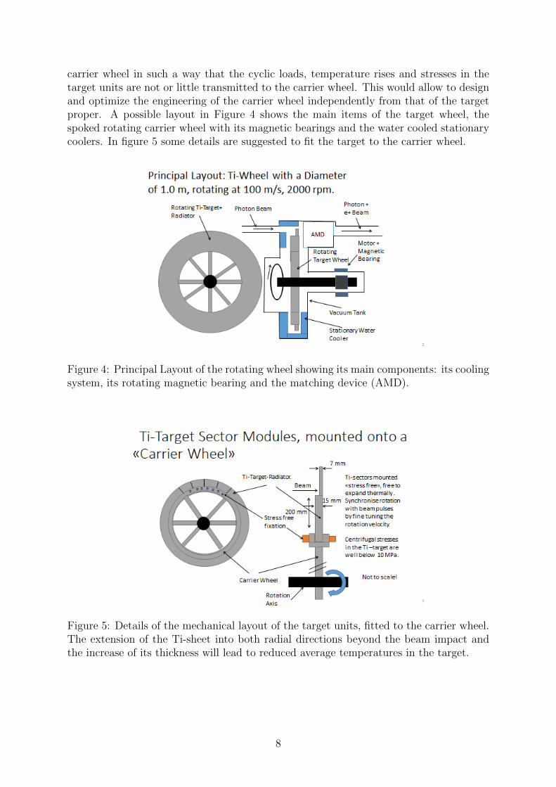
carrier wheel in such a way that the cyclic loads, temperature rises and stresses in thetarget units are not or little transmitted to the carrier wheel. This would allow to designand optimize the engineering of the carrier wheel independently from that of the targetproper. A possible layout in Figure 4 shows the main items of the target wheel, thespoked rotating carrier wheel with its magnetic bearings and the water cooled stationarycoolers. In figure 5 some details are suggested to fit the target to the carrier wheel.
Figure 4: Principal Layout of the rotating wheel showing its main components: its coolingsystem, its rotating magnetic bearing and the matching device (AMD).
Figure 5: Details of the mechanical layout of the target units, fitted to the carrier wheel.The extension of the Ti-sheet into both radial directions beyond the beam impact andthe increase of its thickness will lead to reduced average temperatures in the target.
8

3 Positron yield and OMD
During the long time of design studies for the ILC positron source several options forthe OMD have been considered. An overview is given in reference [16]. The best solu-tion would be a pulsed flux concentrator which initially was envisaged for the adiabaticmatching device (AMD). But in further detailed studies it appeared that over the longpulses of about 1 ms the field in the FC could not be kept stable in time [5]. Further,studies [15] showed that the peak energy deposition in the center at the front of theFC is too high for ILC250. Neither a larger FC aperture nor a shorter distance of FCto undulator could improve the situation substantially. Therefore, further studies werepursued with a QWT. Following reference [16], only a yield Y ≤ 1 e+/e− can be reachedfor electron beam energies of 125 GeV. Studies [15] showed that for the thinner conver-sion target, a maximum K value (K = 0.92) and an optimized B field the yield can beincreased to the required value. Figure 6 demonstrates the influence of the magnetic fieldshape on the positron yield. If the magnetic field rises from almost zero at the target exitwithin 8 mm to a maximum value of 1.04 T, a yield of about 1.5e+/e− can be reached byincreasing K to 0.92. It is the question whether a QWT with the corresponding optimum
dt2qwt = 7.6 mm
Figure 6: Left: Shape of the magnetic field on axis of the QWT. The yellow line showsthe field as used for the simulation studies with an ’ideal’ OMD to achieve the requiredpositron yield. The black line gives the B field as suggested for the QWT in reference [16].The magenta line is the corresponding approximation used for the simulation of thepositron yield. Right: Positron yield depending on the distance dt2qwt assuming a fielddistribution as given with the yellow and magenta line of the left plot. The undulator Kvalue is K = 0.85.
magnetic field is possible, i.e. maximum field of ≈ 1 T at a distance of 7–8 mm from thetarget and almost zero at the target. Studies have shown that a high magnetic field atthe target increases substantially the positron yield. However, the eddy currents createdin the spinning target are considered as drawback since they heat the target Even if theheating is acceptable, brake effects have to be taken into account.
3.1 Magnetic field in target
The positron yield at low centre-of-mass energies (ILC250, GigaZ) cannot be increasedwith a longer undulator but with an optimization of the B field in the matching section
9

the required yield of 1.5 e+/ e− could be reached.As a first approach to study the influence of the B field at the exit side of the target
on the positron yield the simplified field profiles shown in figure 8 have been used. Suchfields can be achieved in a conical solenoid as sketched in figure 7.
20 4 6 8 10 12
33
44
55
66
TargetWheel
z [cm]
Bz(r=0) [T]r [cm]
Accelerator
Figure 7: B field as used for the studies to increase the positron yield.
B [T
]
0
1
2
3
4
5
z [mm]0 20 40 60 80 100 120 140
B(z=0) = 2.8 T B(z=0) = 0
Yield
[e
+/e
- ]
1
1.1
1.2
1.3
1.4
1.5
A B C
QW
TB
targ
et =
0
Bm
ax =
1.0
4 T
DZ
0T-
to-1
.04
T =
7.6
mm
Puls
ed S
ole
noid
Bta
rget =
2.8
T,
Bm
ax =
5 T
DZ
2.8
T-to
-5T =
10
mm
Puls
ed S
ole
noid
Bta
rget =
0 T
,B
max =
5 T
DZ
0T-
to-5
T =
10
mm
Figure 8: Left: B field options as used for the studies to increase the positron yield.Right: Comparison of the positron yield for three B field options.
Figure 8 compares the positron yield results assuming three different B field optionsand demonstrates that the required positron yield can be realized.
As demonstrated in figure 9, further studies are necessary to adjust the B field profilefor highest positron yield. In section 4 the possible design of a pulsed matching systemand its influence on the spinning target is discussed.
10

Yiel
d [e
+ /e- ]
1.2
1.3
1.4
1.5
1.6
1.7
Btarget [T]0.5 1 1.5 2 2.5 3
Bmax [T]1 2 3 4 5
Figure 9: Expected positron yield depending on the field Btarget at the target exit and onthe maximum field Bmax.
11

4 Design of an Optical Matching Device: A pulsed
solenoid
A special feature of the undulator driven positron source is the 1 ms long photon pulse,incident on the rotating wheel. This is much longer than usually used for conventionalpositron sources with micro-second pulses where Flux concentrators (FC) are convenientfor such beam structures. However, due to time varying skin effect in these FC, whendriven with ms-pulses, the magnetic field will strongly vary during the beam pulse [5,16].To circumvent this problem for the ILC, a basically simple solenoid , wound in a conicalshape (see figure 7) is considered; see also reference [25]. Pulsed solenoids as adiabaticmatching device (AMD) have been used in the past, as e.g. for the positron source ofCERN-LEP. To achieve multi-Tesla fields, currents of about 50 kA or above are required.Clearly, with such high currents, the solenoid cannot be driven in a d.c. mode, but hasto be pulsed. Considering a Cu-conductor of about 1 cm×1 cm, the pulse duration hasto be chosen long enough, so that at the peak of the half-sine pulse, eddy current havedied out and a stable field over the duration of the beam pulse of 1 ms is achieved. Sucha stability will be reached with a half sine current pulse with a duration of about 4 ms,where the skin depth in Cu will be about 0.6 cm, sufficiently larger than the averageradius of the conductor with a resistivity of 4× 10⁻⁸ Ωm. This pulsing will still providea large reduction of the electrical power consumption of the solenoid with a duty cycle ofonly 1%, when driven at 5 Hz. In table 2 some design figures are quoted.
Half sine pulse duration 4 msPeak current 50 kARepetition rate 5 HzAverage electrical power 6 kWWater cooling flow 0.17 l/sTemperature rise in cooling water 9 KPeak magnetic field 5.2 TField at target 3 TField at target with upstream booster coil 4 TStress due to magnetic field ≤ 40 MPaBeam induced effects at entrance of the solenoid, r=1 cm PEDD 13 J/gAverage beam power deposition 600 W/cm3
Thermal stress ≈ 100 MPadisplacement per atom (dpa) 0.15/5000 h
Table 2: Design figures for a conical pulsed solenoid, as sketched in figure 7. The inputsfor the beam induced effects were provided by T. Takahashi (Univ. Hiroshima) and A.Ushakov (Hamburg University).
As can be seen in table 2, the pulsing and cooling of the envisaged pulsed solenoid isfeasible. However, detailed engineering is required to provide radiation resistant ceramicinsulations between the windings as well as solid mechanical clamps, applied to the coil,to retain the pulsed forces, stresses and vibrations.
As shown in table 2, for small apertures of 2 cm diameter at the entrance of thesolenoid, the effects induced by the beam at this entrance, become relevant. Thermalfatigue and radiation damage may occur. Therefore, at this stage, larger diameters of the
12

entrance of about 3 cm or above should also be considered. To compensate for the loss offield, a booster coil placed upstream of the target could recuperate part of the field loss,as indicated in figure 10.
Figure 10: By adding an upstream Booster Solenoid, powered in series with the down-stream conical solenoid, an axial field, as indicated by the arrow, of up to 4 T can be’dragged’ through the target.
Some very preliminary calculations of the positron yield have been made by M. Fukuda(KEK) [26] for the conical solenoid as illustrated in figure 11. The increase of the yield is
Figure 11: Magnetic field in the conical solenoid used for first positron yield calcula-tions [26].
striking. Therefore, further studies of this scheme at even higher magnetic fields shouldbe pursued.
4.0.1 Magnetic effects from the pulsed solenoid on the rotating wheel
In a very basic approach to this problem, one can write down the following equations:
∂Bz(r)
∂t=∂Bz(r)
∂r· ∂r∂x· ∂x∂t
=∂Bz(r)
∂rcos(α) · v (4)
13

For definitions see figure 12 describing a magnetic field Bz(r) with rotational symmetry.
Figure 12: Geometry of the axial magnetic field Bz in rotational symmetry which pene-trates through the rotating wheel.
Equation 4 describes the field variation to which any point in the rotating target issubmitted. In particular, field rises occur only in the ’gradient zone’ where ∂Bz/∂t 6= 0.This situation is equivalent to a non-rotating, stationary target submitted to a linearrising field ∝ t/τ in the ’gradient zone’ with a rise time τ = ∆r/v .
From this, the time variation of the magnetic flux, the induced voltage ∂Φ/∂t can beestimated by integration of ∂B/∂t over that surface of the Ti-target, ∂Φ/∂t =
∫∂B/∂t·df ,
which is submitted to the flux change from the solenoid. Finally, by Ohm’s law the currentdensity j(r, α) = σ∂Φ/∂t/
∮ds can be evaluated. This then results in the power W and
braking Lorentz forces FL to which the rotating wheel is submitted:
W =1
σ·∫j2dV ∝ σB2
0v2
FL =
∫jBdV ∝ σB2
0v .
As has been pointed out in references [27, 28], for Ti with its low electrical conductivity,σ = 5.8 × 10⁵ Ω−1m−1, and with the time duration for any point of the wheel which ittakes to traverse the non-zero-gradient zone –assumed here of 1 cm width– the field willhave a rise time of 10−4 s. This, in turn, will lead to a skin depth of about 1.5 cm in theTi-target, which is larger than its thickness of 0.7 cm. Therefore it is plausible that onlyinduced currents from a slowly varying field can be considered while eddy currents can beignored. This is also confirmed by more detailed studies in reference [27], which clearlydemonstrates the above quoted dependencies of the average power and torque from therotation velocity. The absolute values of W and FL however, depend on the shape of themagnetic field and the volume of the Ti-target, submitted to this field.
For the magnetic field of B0 = 4 T, assumed in this study (see figure 12), peakcurrent densities j of about 1.9×10⁷ A/m2 have been estimated, which in turn lead to atmost 10 kW of power deposited in the Ti-target, when a d.c. magnetic field is assumed.Now, applying the duty cycle of 1% due to the pulsed operation of the solenoid, theactual average power deposited in the target, will be around 100 W. This should be welltolerable, in comparison to the beam power of 2 kW.
14

Concerning the pulsed braking forces, they are very pessimistically given by
F =10kW
v= 100N/pulse
or a torque of 50 Nm/pulse, because in reality all induced currents contribute to the powerwhile only those in radial direction contribute to the braking. The braking energy perpulse, extracted from the wheel over 4 ms, amounts to 40 J/pulse. Relating this to thetotal kinetic energy stored in the rotating wheel of about 0.5 MJ, this is large comparedto the braking energy per pulse. However, these braking pulses at 5 Hz will accumulateover time and a slow correction of the rotation velocity within 1–2 s will be necessary tomaintain the nominal velocity within the required range of ±2× 10⁻⁴.
As has been discussed in references [29,30], a parasitic magnetic field will be createdby the currents, induced in the Ti-target. This will superpose and deform the originalfield from the solenoid. Since most of the currents induced in the target, flow into radialdirection (see reference [28]), they will create a parasitic transversal field in the x-directionof the velocity, inside and close to the target surface. Taking the above quoted currentdensity j of 1.9 × 10⁷ A/m2, a transverse field of about 0.14 T must be expected at thelocation close to the target. This will create a systematic field deformation, a transversefield component, as well as a field drag of the original field. According to reference [29,30],a correction by a simple dipole field may have to be applied. Finally thoughts have tobe given to the return field around the solenoid. Its penetration into the rotating wheelmay still deposit additional power in the target. An iron flux trap around the solenoidmay be required.
5 The R&D path towards the undulator driven tar-
get
Further studies of the mechanical design and response of the beam induced thermal loadsare required, also to optimise the geometry of the spinning wheel and of the target, toimprove further the evacuation of the power by radiation.
In case of high luminosity upgrade the temperature in the target increases and ahigher heat evacuation efficiency is desired. The efficiency of cooling could be improvedfurther by conducting the beam power from the Ti target into a radiator which is arrangedclose to the target and has a higher thermal conductivity and which can tolerate highertemperatures. Among other things, Graphite, copper and high temperature Ni- andCo-alloys may be considered. These investigations should be done by finite elementcomputations and be validated, as proposed earlier, by simple laboratory test setups.
Clearly, the proposed design of the pulsed solenoid has to be validated in terms of lifetime and field quality and with emphasis on its radiation resistance.
The quality of the magnetic field must be studied in detail, in particular the increasingtransverse field components towards larger radii inside the aperture of the solenoid, asillustrated in figure 11. As stated above, the magnetic effects from the pulsed solenoidon the spinning wheel can efficiently be simulated by computer codes and initially bebenchmarked with a stationary wheel submitted to a fast pulsed dipole magnet. However,a complete prototype will be necessary to validate the final design.
15

6 Polarization of positrons
There is a continuing discussion whether the realization of an electron driven positronsource is more easy the the construction of the undulator driven positron source. How-ever, at the ILC the electron driven source delivers only an unpolarized positron beam.Thus, the decision about the positron source must include also the relevance of a polar-ized positron beam for the intended physics measurements.Future high-energy e+e− linear colliders will probe the Standard Model and physics be-yond with excellent precision. Besides linear colliders also circular e+e− collider projectsas FCC-ee and CEPC are under discussion [31]. FCC-ee and CEPC could operate atenergies up to about 350 GeV centr-of-mass energy and promise measurements with ex-cellent accuracy below the per mil level. In particular at the Z boson resonance theycan easily produce a factor 1000 more events than it would be possible with the so-calledGigaZ option of the ILC.
Electroweak interactions do not conserve parity, so beam polarization is essential tomeasure and to disentangle new phenomena beyond the Standard model (SM). It isexpected that such phenomena can be directly obtained at high collision energies butalso by deviations from the SM prediction at lower energies as planned for FCC-ee andCEPC. The lessons from the SLC experiment at the the SLAC linear collider showed thatcertain parameters are measured with substantially higher precision if both beams, i.e.electrons and positrons, are polarized. Although the 4 LEP experiments collected a morethan 30 times higher number of Z boson events than SLC, they measured the effectiveweak mixing angle with the same precision.
What is the situation comparing ILC, in particular ILC250 and GigaZ [32], with FCC-ee and CEPC? High degrees of electron beam polarization are possible; the ILC e− beamwill be at least 80% polarized. Since the generation of an intense (polarized) positronbeam is a challenge, simultaneously polarized e− and e+ beams at linear colliders areunder discussion since many years. Without going in details as physics processes andtheir analyses, the benefit of polarized positron beams is given by the following reasons(see also references [33–35]):
• There are 4 combinations of e+ and e− helicity states in the collision of high-energyelectrons and positrons. Only with both beams polarized each of these initial statecombinations can be explicitly realized in a collider.
• With the ’right’ helicity combination of initial states a higher effective luminosityis achieved: Leff/L = 1 − (1 − Pe−Pe+). A higher number of specific events isachieved in shorter running time. For example, assuming Pe− = 90% and Pe+ = 30%the effective luminosity can be almost a factor 1.3 higher than without positronpolarization.
• The suppression of background is crucial for precision measurements. With polar-ized beams the desired initial states can be enhanced or suppressed. This improvesthe discrimination and control of background processes.
• Polarized beams provide a high flexibility to evaluate systematic effects. It is verydifficult to detect and correct time-dependent effects, correlations or a bias in thepolarimeter measurement. If both beams are polarized, such systematic effects canbe much better controlled, and their impact on the uncertainty of observables canbe substantially reduced down to negligible values.
16

• In case of deviations from the Standard Model predictions, polarization of bothbeams enhances significantly the possibility to confirm the existence of a new phe-nomenon: High precision, flexible configuration of initial states and a larger numberof independent observables could even allow to unravel underlying physics.
• An independent determination of beam polarization and left-right asymmetries isonly possible if both beams are polarized.
One should keep in mind that also the zero polarization of an unpolarized positron beammust be confirmed to avoid any bias in the physics analyses [36].All these arguments suggest that positron polarization is crucial for precision measure-ments at ILC250 and inevitable for GigaZ.
17

7 Summary
The positron source based on a helical undulator is the baseline option for the positrongeneration at the ILC. It is preferred to the electron driven scheme for several reasons:the power absorption in the target and the source facilities is substantially lower, lessneutrons are generated and the target system is less activated. Further, the sensitivityto changes of the positron damping ring is lower. And most important for the precisionmeasurements and the ILC physics goal is the delivery of a positron beam which is atleast 30% polarized.
The undulator based ILC positron source has been intensively studied in the past andhas undergone various modifications and improvements. It has been demonstrated thatthis source with the required performance, and in particular with the required positronyield of 1.5 e+/e− is technically feasible. Its essential components consist of the Ti-targetwith a thickness of 7 mm for ILC250, shaped into a wheel with a diameter of 1 m androtating in vacuum at 2000 rpm. The average beam power of about 2 kW which isdeposited in the target at nominal luminosity, is evacuated by heat radiation from thesurface of the wheel into a stationary, water cooled heat sink.
Due to the particular long photon beam pulse of 1 ms at 5 Hz, for the positroncollection system, an efficient Adiabatic Matching Device, AMD, is required. Flux con-centrators as used elsewhere, i.e. SLAC, SKEKB, are operated at micro-s pulse durations;they are not well suited for the long beam pulse of 1 ms. In reference [5], the positroncollection system for the undulator scheme with long beam pulses has been stated as oneof the open issues. Here, a possible technical solution is proposed, by which this issuecan be resolved by a pulsed solenoid collector. A solenoid driven with pulses of 4 msduration and at 5 Hz has been studied. Such a device can provide peak fields of about 5T in the solenoid while 2-3 T fields can be tolerated at the rear of the Ti-wheel, withoutexcessive additional heating and braking of the spinning wheel. Some possible designmodifications of the wheel, to improve further its cooling, and the technical R&D pathtowards the development of the essential parts of the undulator driven source have beenoutlined.
Acknowledgment
This work was partially supported by the German Federal Ministry of Education andResearch, Joint Research Project R&D Accelerator ”Positron Sources”, Contract Num-ber 05H15GURBA. The fruitful discussions on the AMD with M. Fukuda/KEK, L. Ri-nolfi/CERN and R. Chehab/LAL are gratefully acknowledged. We thank Felix Dietrichfor his contributions to the positron target project.
18

References
[1] T. Behnke et al. The International Linear Collider Technical Design Report - Volume1: Executive Summary. 2013.
[2] C. Adolphsen et al. The International Linear Collider Technical Design Report -Volume 3.I: Accelerator & in the Technical Design Phase. 2013.
[3] C. Adolphsen et al. The International Linear Collider Technical Design Report -Volume 3.II: Accelerator Baseline Design. 2013.
[4] F. Dietrich, G. Moortgat-Pick, S. Riemann, P. Sievers, A. Ushakov. Status of theundulator-based ILC positron source. In International Workshop on Future LinearColliders (LCWS 2018) Arlington, Texas, USA, October 22-26, 2018, 2019.
[5] K. Yokoya (ed.), Positron Working Group W. Gai et al. Report on the ILC PositronSource, May 23 2018. https://edmsdirect.desy.de/item/D00000001165115.
[6] T. Omori et al. A conventional positron source for International Linear Collider.Nucl. Instrum. Meth., A672:52–56, 2012.
[7] H. Nagoshi et al. A design of an electron driven positron source for the internation-allinear collider. Nucl. Instrum. Meth., A953:163134, 2020.
[8] H. Aihara et al. The International Linear Collider. A Global Project. 2019.
[9] D. J. et al Scott. Demonstration of a High-Field Short-Period SuperconductingHelical Undulator Suitable for Future TeV-Scale Linear Collider Positron Sources.Phys. Rev. Lett., 107:174803, Oct 2011.
[10] S. Riemann, F. Dietrich, G. Moortgat-Pick, P. Sievers, A. Ushakov. The ILC positrontarget cooled by thermal radiation. In International Workshop on Future LinearCollider (LCWS2017) Strasbourg, France, October 23-27, 2017, 2018.
[11] A Ushakov. Talk given at POSIPOL, August 2016, Orsay, France.
[12] A. Ushakov, V. Kovalenko, G. Moortgat-Pick, S. Riemann, F. Staufenbiel. Simula-tions of the ILC Positron Source at Low Energies. In Proceedings, 4th InternationalParticle Accelerator Conference (IPAC 2013): Shanghai, China, May 12-17, 2013,page TUPME003, 2013.
[13] A. Ushakov. Positron Yield Calculations for the Undulator Based Source at 250GeV CM Energy. talk given at the Asian Linear Collider Workshop ALCW2018 inFukuoka, Japan, 28th May – June 2nd, 2018.
[14] J. Gronberg et al. Prototyping of the ILC Baseline Positron Target. In InternationalWorkshop on Future Linear Colliders (LCWS11) Granada, Spain, September 26-30,2011, 2012.
[15] A. Ushakov, G. Moortgat-Pick, S. Riemann. Undulator-Based Positron Source at250 GeV CM Energy with Different Optical Matching Devices: Pulsed Flux Concen-trator and Quarter Wave Transformer. In International Workshop on Future LinearCollider (LCWS2017) Strasbourg, France, October 23-27, 2017, 2018.
19

[16] W. Liu, W. Gai, L. Rinolfi and J. Sheppard. An Undulator based Polarized PositronSource for CLIC. Conf. Proc., C100523:THPEC035, 2010.
[17] J. Gronberg et al. Talk given at POSIPOL Workshop, 4-6 September 2013, ArgonneNational Laboratory, USA.
[18] P. Sievers. Talk given at POSIPOL, August 2014, Ichinoseki, Japan.
[19] P. Sievers. Talk given at POSIPOL Workshop, 14-16 September 2016, LAL Orsay,France.
[20] K.C. Mills. Recommended Values of Thermophysical Properties for Selected Com-mercial Alloys. 1st edition, 2002, eBook ISBN: 9781845690144, Woodhead Publish-ing.
[21] ANSYS. http://www.ansys.com.
[22] A. Ushakov et al. Material Tests for the ILC Positron Source. In Proceedings, 8thInternational Particle Accelerator Conference (IPAC 2017): Copenhagen, Denmark,May 14-19, 2017, page TUPAB002, 2017.
[23] P. Heil, K. Aulenbacher, T. Beiser et al. High Energy Density Irradiation WithMAMI LINAC. In Proceedings, 8th International Particle Accelerator Conference(IPAC 2017): Copenhagen, Denmark, May 14-19, 2017, page TUPAB003, 2017.
[24] A. Ushakov. Acceptable Peak Temperature and Thermal Stress in Ti6Al4V Targetof ILC Positron Source. Talk given at POSIPOL Workshop, 3-5 September 2018,Geneva, Switzerland.
[25] P. Sievers. Talk given at the POSIPOL Workshop, 3-5 September 2018, Geneva,Switzerland.
[26] M. Fukuda. private communication, 2019.
[27] I. Bailey et al. Eddy Current Studies From the Undulator-based Positron SourceTarget Wheel Prototype. Conf. Proc., C100523:THPEC033, 2010.
[28] W.R. Smythe. On eddy currents in a rotating disk. Electrical Engineering, 61 no.9:681–684, Sept. 1942.
[29] S. Antipov, L. Spentzouris, W. Liu, W. Gai. Numerical studies of InternationalLinear Collider positron target and optical matching device field effects on beam. J.Appl. Phys., 102:014910, 2007.
[30] S. Antipov, L. K. Spentzouris, W. Liu, W. Gai. Simulations of the Rotating PositronTarget in the Presence of OMD Field. Conf. Proc., C070625:2909, 2007. [2909(2007)].
[31] A. Abada et al. FCC-ee: The Lepton Collider. Eur. Phys. J. ST, 228(2):261–623,2019.
[32] Kaoru Yokoya, Kiyoshi Kubo, and Toshiyuki Okugi. Operation of ILC250 at theZ-pole. 2019.
20

[33] G. Moortgat-Pick et al. The Role of polarized positrons and electrons in revealingfundamental interactions at the linear collider. Phys. Rept., 460:131–243, 2008.
[34] R. Karl and J. List. Polarimetry at the ILC. In Proceedings, International Workshopon Future Linear Colliders 2016 (LCWS2016): Morioka, Iwate, Japan, December05-09, 2016, 2017.
[35] R. Karl. From the Machine-Detector Interface to Electroweak Precision Measure-ments at the ILC – Beam-Gas Background, Beam Polarization and Triple GaugeCouplings. PhD thesis, Hamburg U., Hamburg, 2019.
[36] K. Fujii et al. The role of positron polarization for the inital 250 GeV stage of theInternational Linear Collider. 2018.
21
Related Documents