Update on the state of technology for a critical-angle x-ray transmission grating spectrometer on the X-ray Surveyor X-ray Surveyor technology teleconference Ralf Heilmann, Alex Bruccoleri (Izentis LLC), Mark Schattenburg Space Nanotechnology Lab MIT Kavli Institute for Astrophysics and Space Research June 15, 2016

Welcome message from author
This document is posted to help you gain knowledge. Please leave a comment to let me know what you think about it! Share it to your friends and learn new things together.
Transcript

Update on the state of technology for a critical-angle x-ray transmission grating
spectrometer on the X-ray Surveyor
X-ray Surveyor technology teleconference
Ralf Heilmann, Alex Bruccoleri (Izentis LLC), Mark Schattenburg Space Nanotechnology Lab
MIT Kavli Institute for Astrophysics and Space Research June 15, 2016
Why CAT Gratings?
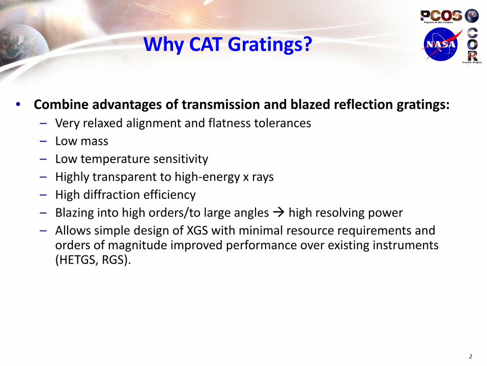
• Combine advantages of transmission and blazed reflection gratings: – Very relaxed alignment and flatness tolerances – Low mass – Low temperature sensitivity – Highly transparent to high-energy x rays – High diffraction efficiency – Blazing into high orders/to large angles high resolving power – Allows simple design of XGS with minimal resource requirements and
orders of magnitude improved performance over existing instruments (HETGS, RGS).
2

Technical Background: CATXGS Design
3
X’
Y’
CAT grating arrays
Focal plane view
Optical Design: – Wolter I (or similar) telescope mirrors. – Diffraction gratings in converging beam just aft of mirrors. – Gratings, camera, and focus share same Rowland torus. – Blazed gratings; only orders on one side are utilized. – Only fraction of mirrors is covered: “sub-aperturing”.

CAT Grating Principle
4
Silicon grating, θ = 1.75o
p = 200 nm b = 40 nm d = 5.2 µm Aspect ratio d/b = 125
βm

Model Diffraction Efficiencies
5
*
*neglecting losses from supports
Theoretical model: Rigorous Coupled-Wave Analysis (RCWA) Parameters: wavelength λ, index of refraction n, period p, depth d, duty cycle b, angle of incidence θ
Absorption due to CAT grating bars already included in model, but not losses from additional structural supports (L1, L2, etc.)

Model Diffraction Efficiencies
6
0
0.1
0.2
0.3
0.4
0.5
0.6
0.7
0.8
0.9
0 2 4 6 8 10
0 1st
2nd 3rd
4th 5th
6th 7th
8th 9th
10th 11th
12th Sum
wavelength [nm]
abso
lute
diff
ract
ion
effic
ienc
y
Silicon grating, θ = 1.75o
p = 200 nm b = 40 nm d = 5.2 µm Aspect ratio d/b = 125
*neglecting losses from supports
for AEGIS design parameters
AEGIS wavelength band

Blazing at Different Wavelengths
7
θ = 1.14 deg X-ray data Scanning wavelength: Blaze peak width ~ λ Small λ blaze in higher order m
λc(θ=1.14 deg) ~ 0.9 nm
Inte
nsity
[arb
itrar
y]
Heilmann et al., Proc. SPIE 74370G (2009)

Blazing and Alignment Insensitivity
8
λ = 6.8 nm X-ray data “rocking” the grating: Blaze angle ~ 2θ Diffraction angle ~ const.
Inte
nsity
[arb
itrar
y]
Heilmann et al., Proc. SPIE 74370G (2009)

Raytracing and Resolving Power
9
• Boosting resolving power through sub-aperturing:
– Sub-aperturing takes advantage of anisotropic scattering in grazing-incidence reflective optics.
– Align dispersion direction with narrow dimension of anisotropic PSF → increase spectral resolution by factor 3-5.
Figure courtesy of D. Robinson

Raytracing and Resolving Power
10
AEGIS as a probe-size reference mission (10” mirror PSF)
Reso
lvin
g Po
wer
E/∆
E
Energy [keV]
http://pcos.gsfc.nasa.gov/studies/rfi/Bautz-Marshall-RFINNH11ZDA018L.pdf
requirement

CAT Grating Structure: “Unit Cell”
11
(not to scale)
(200 nm period)
(5-10 micron period)
{111} planes

Fabr
icat
ion
Proc
ess
12
Bulk Silicon (500 µm)
Device Silicon (4 µm)
1. Start with SOI wafer
300 nm thermal SiO2
PECVD SiO2 (4 µm)
500 nm buried SiO2
2. Pattern front and back side SiO2
3. DRIE front side and stop on SiO2
4. Fill front side gratings with photoresist
Photoresist (10 µm)
Crystal Bond
Carrier Wafer
5. Flip over, bond to carrier wafer with crystalbond under vacuum, DRIE handle layer
7. Remove buried SiO2 and SiO2 front side mask via vapor HF
locate & align to {111} planes
6. Separate from carrier in hot water, piranha clean twice and critical-point dry
polish in KOH after DRIE
Combining D
RIE with
KOH Polishing
Heilm
ann
et a
l., P
roc.
SPI
E 96
0314
(20
15)

CATXGS Structural Hierarchy
13
GRATING ARRAY
STRUCTURE (GAS)
GRATING FACET (MEMBRANE & FRAME)
LEVEL 2 SUPPORTS
LEVEL 1 SUPPORTS
EXAMPLE:
AEGIS
MIRROR
ARRAY
GRATING
ARRAY
READOUT
CAMERAS
MIRROR
ARRAY
GRATING
ARRAY

Key Performance Parameters/Technical Targets
• Grating “throughput” (effective area) – Flow down from science requirement for effective area. – Mirror design gives mirror effective area and aperture to be covered by gratings. – Losses reduce mirror effective area:
o Blockage from grating support structures (GAS, facet frames (L3), L2, L1) o Gaps between grating facets o Diffraction efficiency < 100% o Detector size and readout/quantum efficiency
– Realistic grating throughput goal: > 0.3 • Resolving Power
– Flow down from science requirements – Requirement: R = λ/∆λ = 3500 – Determined by
o Mirror design, mirror PSF, error distribution within mirror PSF o Assembly and alignment errors o Optical design (focal length, Rowland torus parameters, sub-aperture azimuth, grating size,
blaze angle) o Grating period variation ∆p/p o Detector pixel size o Thermal expansion o Spacecraft pointing
14

Technical Status
• Major milestones – Developed front and backside DRIE process -> freestanding gratings with narrow L1
supports – Integrated KOH polishing into process for smoother sidewalls – Confirmed theoretical diffraction efficiency predictions with synchrotron
measurements over wide band of wavelengths, angles, and grating parameters (several publications in peer reviewed literature; see http://snl.mit.edu)
– Fabricated and x-ray tested metal-coated extended-bandpass CAT gratings for resolving power measurements at MSFC Stray Light Facility (SLF)
– Performed resolving power measurements: demonstrated R > 10,000 • Technology Readiness Level 4 (vetted by PCOS Technology Board)
15

Results
• Product: 200 nm-period silicon CAT grating membrane with integrated L1 and L2 supports, > 30x8 mm2.
16
(DRIE only)
L2 support mesh
L1 support bars
~ 33 mm x 33 mm

Recent Samples
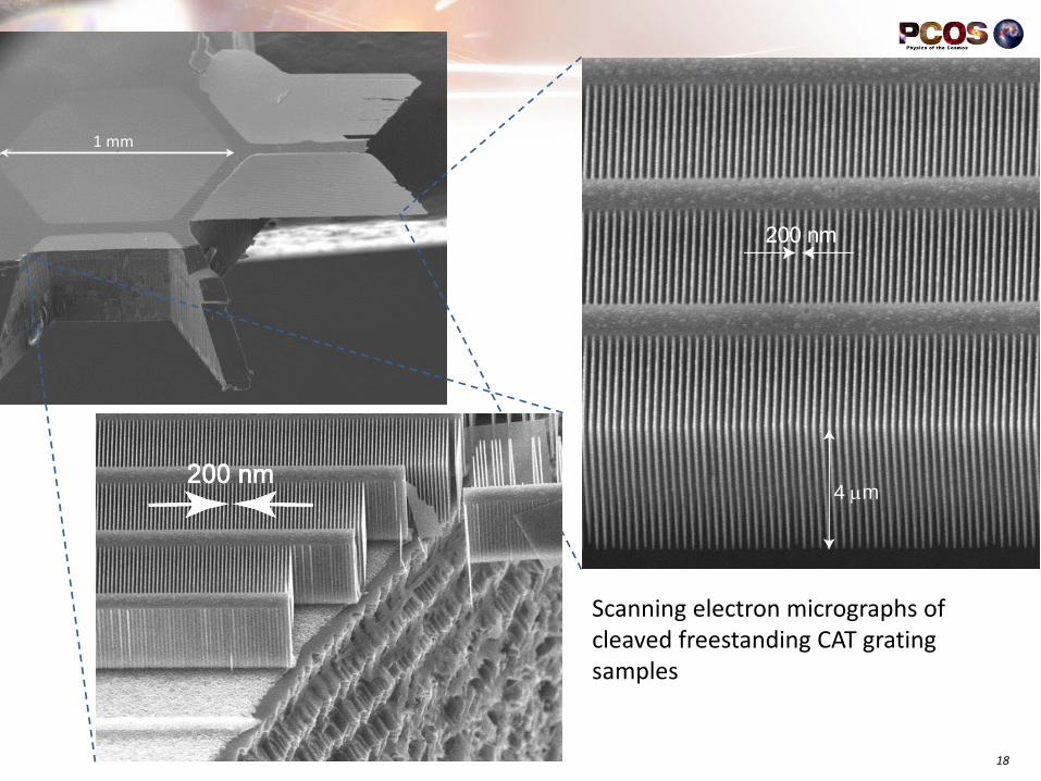
18
1 mm
4 µm
Scanning electron micrographs of cleaved freestanding CAT grating samples

Fabrication Results
Practically defect-free large-area CAT gratings with low-duty-cycle L1 support bars
19
200 nm 1 µm
5 µm

Diffraction Efficiency: ALS Beamline 6.3.2
20
0
0.05
0.1
0.15
0.2
0.25
-1 0 1 2 3 4 5 6diffraction angle [deg]
abso
lute
diffr
actio
n ef
ficie
ncy
6
7
8
diffraction angle [deg]
abso
lute
diffr
actio
n ef
ficie
ncy
6
7
8
(Replaced by CAT gratings under test)
λ = 2 nm

Diffraction Efficiency
21
• Synchrotron data: Sum of efficiencies in blazed orders, reduced by L1 absorption. • Achieved 88% of model prediction at λ = 2.5 nm. • Repeatable fabrication process leads to repeatable performance.
4 µm deep gratings (AEGIS design: 5.2 µm)
Heilmann et al., Proc. SPIE 960314 (2015)
~32%
0th order goes to focus (calorimeter, CMOS imager)
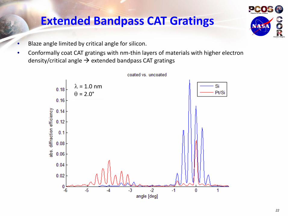
Extended Bandpass CAT Gratings
22
• Blaze angle limited by critical angle for silicon. • Conformally coat CAT gratings with nm-thin layers of materials with higher electron
density/critical angle extended bandpass CAT gratings
λ = 1.0 nm θ = 2.0°

Grating Uniformity
23
• Measure diffraction efficiency of blazed order while scanning grating through the x-ray beam (red curve shifted for clarity, dips due to L2 mesh blockage)

Resolving Power
24
MSFC Stray Light Test facility: Al Kα source (λ ~ 0.83 nm, λ/∆λ ~ 3400), ~ 90 m beam line Focusing Optic: GSFC Technology Development Module (~ 8.5 m focal length) Sub-apertured LSF: ~ 1.5” FWHM in dispersion direction AEGIS requirement: R > 3500. Dispersion angle 1o : R = λ/∆λ ~ 2400 Dispersion angle 3.5o (AEGIS): R = λ/∆λ ~ 8400! Problem: Θc ~ 1.1o for Si CAT gratings at λ = 0.83 nm; current 4 µm deep gratings optimized for ~ 2.0o Solution: Coat Si gratings with PT using ALD -> extended band CAT gratings

MSFC SLF Optical Layout
25

Resolving Power
26
TDM and CAT gratings
CAT gratings during optical alignment
0th order image (~ 1.2” LSF)
18th order image (~ 1.2” LSF)
dispersion axis
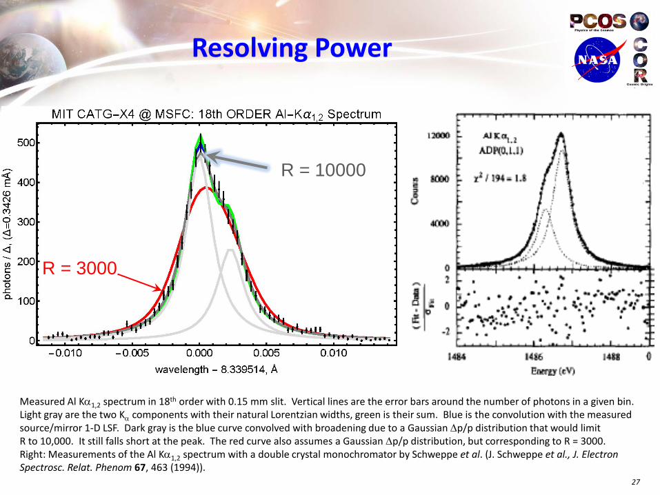
Resolving Power
27
R = 3000
R = 10000
Measured Al Kα1,2 spectrum in 18th order with 0.15 mm slit. Vertical lines are the error bars around the number of photons in a given bin. Light gray are the two Kα components with their natural Lorentzian widths, green is their sum. Blue is the convolution with the measured source/mirror 1-D LSF. Dark gray is the blue curve convolved with broadening due to a Gaussian ∆p/p distribution that would limit R to 10,000. It still falls short at the peak. The red curve also assumes a Gaussian ∆p/p distribution, but corresponding to R = 3000. Right: Measurements of the Al Kα1,2 spectrum with a double crystal monochromator by Schweppe et al. (J. Schweppe et al., J. Electron Spectrosc. Relat. Phenom 67, 463 (1994)).

Resolving Power
28
Measured Al Kα1,2 spectrum with 0.10 mm slit (8 hour exposure). The green curve is a simple one-parameter fit to the sum of two Lorentzians with their quoted natural widths (0.002412 Å), a 2:1 amplitude ratio, and 0.002317 Å spacing. There is very little room for a convolution with the measured LSF (1.0”), and even less room for any broadening due to contributions from the grating.
Preliminary analysis strongly suggests that the tested CAT gratings, illuminated across 30 mm width, are not a limiting factor in the design and construction of blazed transmission grating spectrometers with resolving power on the order of R = λ/∆λ = 10,000.

Future Plans
• Performance demonstration planned – Demonstrate resolving power of GAS with three CAT gratings simultaneously
illuminated with x rays from focusing. Perform pre and post environmental tests.
– Demonstrate effective area with pencil-beam synchrotron measurements of individual gratings; extrapolate from diffraction efficiency and designed and measured dimensions of larger structures (L2, L3, gaps, GAS). o Maximize throughput for both L3 & GAS, and/or o Increase diffraction efficiency by making deeper gratings & narrower bars/L1/L2
• Notional schedule or timeline: TRL5 by end of 2018, based on renewal of SAT funding.
29

Summary • Technology for large-area, high-resolution soft x-ray CAT grating
spectrometer stands at TRL4. Rapid recent progress and performance improvements.
• Status of technology meets/exceeds TRL4 in many respects. – Diffraction efficiency > 85% of maximum at 0.5 keV. – Gratings contain full structural complexity of goal design. – Uniform over surface, reasonable size. – Demonstrated R > 10,000 possible with CAT gratings at 1.48 keV.
• Path forward – Clear and feasible path to TRL5. – Attach gratings to frames and develop alignment technology for CAT grating
array (polarization of visible light, adapted from Chandra HETGS). – Want to improve fabrication yield and x-ray “throughput” further. – Proposed for SAT funding beyond 2016.
30
Related Documents