UNIVERSITY OF CALIFORNIA Los Angeles Up-Conversion of Terahertz Amplitude-Modulated CO 2 Laser Pulses Using Nonlinear Crystals A thesis submitted in partial satisfaction of the requirements for the degree Master of Science in Electrical Engineering by Kari S. Sanders 2001

Welcome message from author
This document is posted to help you gain knowledge. Please leave a comment to let me know what you think about it! Share it to your friends and learn new things together.
Transcript

UNIVERSITY OF CALIFORNIA
Los Angeles
Up-Conversion of Terahertz Amplitude-Modulated CO2 Laser Pulses Using
Nonlinear Crystals
A thesis submitted in partial satisfaction of the requirements for
the degree Master of Science in Electrical Engineering
by
Kari S. Sanders
2001

The thesis of Kari S. Sanders is approved.
Oscar Stafsudd
Warren Mori
Chandrashekhar J. Joshi,Committee Chair
University of California, Los Angeles
2001
ii

TABLE OF CONTENTS
1 Overview . . . . . . . . . . . . . . . . . . . . . . . . . . . . . . . . . . . 1
2 Frequency Conversion in Nonlinear Crystals . . . . . . . . . . . . . . . . 5
2.1 Second Harmonic Generation . . . . . . . . . . . . . . . . . . . . . 6
2.2 Sum Frequency Generation. . . . . . . . . . . . . . . . . . . . . . . 7
2.3 Phase Matching . . . . . . . . . . . . . . . . . . . . . . . . . . . . . 7
2.4 Acceptance Angle . . . . . . . . . . . . . . . . . . . . . . . . . . . 11
2.5 Efficiency . . . . . . . . . . . . . . . . . . . . . . . . . . . . . . . 12
2.6 Group Velocity Mismatch . . . . . . . . . . . . . . . . . . . . . . . 13
3 SFG in AgGaS2 . . . . . . . . . . . . . . . . . . . . . . . . . . . . . . . . 14
3.1 Crystal Selection for the THz Modulator . . . . . . . . . . . . . . . 14
3.1.1 Transparency . . . . . . . . . . . . . . . . . . . . . . . . . 15
3.1.2 Acceptance Angle . . . . . . . . . . . . . . . . . . . . . . . 15
3.1.3 Efficiency. . . . . . . . . . . . . . . . . . . . . . . . . . . . 17
3.1.4 Group Velocity Mismatch . . . . . . . . . . . . . . . . . . . 18
3.1.5 Verification of Crystal Parameters for AgGaS2 . . . . . . . . . 18
3.1.6 Summary . . . . . . . . . . . . . . . . . . . . . . . . . . . . 20
3.2 Phase 1: SFG Using a fiber optic delay line . . . . . . . . . . . . . . 21
3.2.1 Experimental Setup: Block Diagram. . . . . . . . . . . . . . 22
3.2.2 Experimental Setup: Photos . . . . . . . . . . . . . . . . . . 23
3.2.3 Equipment Selection . . . . . . . . . . . . . . . . . . . . . . 24
3.2.4 Experimental Data . . . . . . . . . . . . . . . . . . . . . . . 30
iii

3.3 Phase 2: SFG Using 100 ps CO2 Pulses . . . . . . . . . . . . . . . . 35
3.3.1 Experimental Setup . . . . . . . . . . . . . . . . . . . . . . 35
3.3.2 Theoretical Efficiency and Output Power . . . . . . . . . . . 38
3.3.3 Experimental Data . . . . . . . . . . . . . . . . . . . . . . . 39
3.4 Summary . . . . . . . . . . . . . . . . . . . . . . . . . . . . . . . 42
4 Up-Conversion in KDP . . . . . . . . . . . . . . . . . . . . . . . . . . . 43
4.1 Theoretical Analysis . . . . . . . . . . . . . . . . . . . . . . . . . . 43
4.2 Experimental Data . . . . . . . . . . . . . . . . . . . . . . . . . . 44
5 Detection of Modulation: Autocorrelation . . . . . . . . . . . . . . . . . 46
5.1 Background . . . . . . . . . . . . . . . . . . . . . . . . . . . . . . 46
5.2 Commercial Autocorrelator . . . . . . . . . . . . . . . . . . . . . . 48
5.3 Custom Autocorrelator Design . . . . . . . . . . . . . . . . . . . . 50
5.3.1 Experimental Setup . . . . . . . . . . . . . . . . . . . . . . 51
5.3.2 Experimental Design. . . . . . . . . . . . . . . . . . . . . . 52
5.3.3 Future Work . . . . . . . . . . . . . . . . . . . . . . . . . . 52
6 Conclusion . . . . . . . . . . . . . . . . . . . . . . . . . . . . . . . . . 53
iv

LIST OF FIGURES AND TABLES
Figure 1-1: Concept Overview for PBWA Experiment. . . . . . . . . . . . 1
Figure 1-2: Block Diagram of SFG . . . . . . . . . . . . . . . . . . . . . . 2
Figure 1-3: CO2 Pulse Train . . . . . . . . . . . . . . . . . . . . . . . . . 2
Figure 1-4: Chronological Overview . . . . . . . . . . . . . . . . . . . . . 4
Figure 2-1: Block Diagram of SHG . . . . . . . . . . . . . . . . . . . . . . 6
Figure 2-2: Block Diagram of SFG . . . . . . . . . . . . . . . . . . . . . . 7
Figure 2-3: Diagram of Phase Matching . . . . . . . . . . . . . . . . . . . 8
Figure 2-4: Sample Phase Matching Diagram for Collinear SHG . . . . . . 9
Figure 2-5: Vector Addition for Noncollinear Phase Matching . . . . . . . 9
Figure 2-6: Samples of Phase Matching for Noncollinear SHG . . . . . . 10
Figure 2-7: Sample Intensity Profile . . . . . . . . . . . . . . . . . . . . 12
Table 3-1: Crystal Analysis, Acceptance Angle . . . . . . . . . . . . . . . 15
Figure 3-1: Theoretical Acceptance Angle for AgGaS2 . . . . . . . . . . . 16
Figure 3-2: Phase Matching Curve for AgGaS2 . . . . . . . . . . . . . . . 17
Table 3-2: Crystal Analysis, Group Velocity Mismatch. . . . . . . . . . . 18
Table 3-3: Values for d36 in AgGaS2 . . . . . . . . . . . . . . . . . . . . . 19
Table 3-4: Index of Refraction for 10.59 µm, AgGaS2 . . . . . . . . . . . . 20
Figure 3-3: Phase 1 Block Diagram . . . . . . . . . . . . . . . . . . . . . 22
Figure 3-4: Phase I Photo . . . . . . . . . . . . . . . . . . . . . . . . . . 23
Figure 3-5: Phase I Interaction Point . . . . . . . . . . . . . . . . . . . . 23
Figure 3-6: Beam Profile Data. . . . . . . . . . . . . . . . . . . . . . . . 30
Figure 3-7: Image of Nd:YAG Pulse . . . . . . . . . . . . . . . . . . . . 31
v

Figure 3-8: Nd:YAG Pulse and CO2 Pulse Train . . . . . . . . . . . . . . 32
Figure 3-9: Nd:YAG and a Single CO2 Pulse . . . . . . . . . . . . . . . . 32
Figure 3-10: Spectrometer Image of AgGaS2 Output . . . . . . . . . . . . 34
Figure 3-11: One Line of Spectrometer Data, AgGaS2 Output . . . . . . . 34
Figure 3-12: Phase 2: First Experimental Setup . . . . . . . . . . . . . . 36
Figure 3-13: Crystal Orientation for Phase Matching Angle Scan . . . . . 37
Figure 3-14: Photo of Second Setup for Phase 2 . . . . . . . . . . . . . . 37
Figure 3-15: AgGaS2 Output Intensity Variation with 1 µm Input Energy . 39
Figure 3-16: Angular Dependence of SFG Output in AgGaS2 . . . . . . . 40
Figure 3-17: Non-Collinear Phase Matching, Experimental Setup . . . . 41
Table 4-1: Theoretical Parameters for SHG, SFG in KDP . . . . . . . . . 44
Figure 4-1: Up-Conversion in KDP, Image . . . . . . . . . . . . . . . . . 45
Figure 4-2: Upconversion in KDP, Data . . . . . . . . . . . . . . . . . . 45
Figure 5-1: Experimental Setup for Autocorrelation . . . . . . . . . . . . 48
Figure 5-2: Collinear SHG in SSA with 1 µm Pulse, Path 1 . . . . . . . . . 49
Figure 5-3: Noncollinear SHG with two 1 µm Pulses . . . . . . . . . . . . 49
Figure 5-4: Collinear SHG in SSA with 1 µm Pulse, Path 2 . . . . . . . . . 50
Figure 5-5: Block Diagram of Custom Autocorrelator . . . . . . . . . . . 51
Figure 5-6: Photo of Custom Autocorrelator . . . . . . . . . . . . . . . . 51
vi

ACRONYMS AND ABBREVIATIONS
AgGaS2 Silver Gallium Di-Sulphide, Silver Thiogallate
CCD Charge-Coupled Device
CO2 Carbon Dioxide
CW Continuous Wave
eV Electron Volts, 1.6x10⁻¹⁹ Joules per eV
FWHM Full Width at Half Maximum
HeNe Helium Neon. A HeNe laser produces red light (632 nm) and was used for optical alignment.
KDP Potassium Dihydrogen Phosphate, KH2PO4
Nd:YAG Neodymium, Ytrium, Arsenic, Garnet
mJ Milli-Joules, 10-3 Joules
µm Micrometer, 10-6 meters
nm Nanometer, 10-9 meters
PBWA Plasma Beat-Wave Acceleration
ps Pico-seconds, 10-12 seconds
SFG Sum Frequency Generation
SHG Second Harmonic Generation
SSA Single Shot Autocorrelator
THz Terahertz, 1012 Hertz
UV Ultra-Violet
VNIR Very Near Infrared
ZnSe Zinc Selenide
vii

ACKNOWLEDGMENTS
From UCLA, I thank Chan Joshi for his support and guidance. Thanks to Sergei
Tochitsky many hours he has spent helping me in the lab and reviewing this paper.
Thanks also to Catalin Filip for the time he spent on my project; to Ritesh Narang,
Maria Guerrero, Ken Marsh, Chris Clayton, and Jerzy Hoffman for their help.
From Raytheon, I thank Bob Burley, Bob Knopf, and Angela Phillips, for their
support throughout this process, as well as Todd Johnson and Robin Reeder for
their advice re optical design.
Thanks to Kristin for the hours of consul and the benefit of her experiences.
Thanks to Ali for all his encouragement and scholastic help. Thanks to Warren for
patiently sitting through all my stories and for reviewing this paper. Thanks to
Karen, Howard, Angela, Pete, Tim, Jeff, Jake, Laurie, Sacha, Todd, Alex, and Jarl
for listening to my tales over and over and over again.
Thanks to our late cat, Gracie, for fuzz therapy and always being a joy to come
home to.
Much thanks to my parents, my brother, Mike’s parents, both our families, Eleanor,
and Bill for their support and encouragement.
Most of all, thanks to my dear husband, Mike, for his enduring patience, for
providing both encouragement and sympathy, for surviving my hectic schedule,
and for always being there when I needed him.
viii
ABSTRACT OF THE THESIS
Up-Conversion of Terahertz Amplitude-Modulated CO2
Laser Pulses Using Nonlinear Crystals
by
Kari S. Sanders
Master of Science in Electrical Engineering
University of California, Los Angeles, 2001
Professor Chandrashekhar Joshi, Chair
The purpose of this project was to demonstrate the up-conversion of THz
modulation in a 10 µm optical signal using a nonlinear crystal, AgGaS2. The
motivation for this project is its possible application to the Plasma Beatwave
Acceleration experiments. For these experiments, the electrons produced by the
photocathode of an RF gun must be injected in phase with a relativistic plasma
wave in order to experience acceleration. The plasma wave is produced using the
beat frequency of two CO2 laser wavelengths - 10.27 and 10.59 µm. Since the
photocathode requires UV light to efficiently produce electrons, the proposed
method of synchronizing the laser pulses with the electrons was to up-convert the 1
THz modulation at 10 µm three times using nonlinear crystals. The first crystal
would produce Near-IR light, the second green, and the third UV. This project was
a proof-of-principle experiment for the first stage of up-conversion.
ix

The AgGaS2 crystal was chosen because it is transparent to the wavelengths used and
the group velocity mismatch between the incident wavelengths is sufficiently less
than 1 ps to not distort the THz modulation as it passes through the medium. Sum
Frequency Generation (SFG) was used to up-convert the laser pulses to 964 nm (SFG
of 1.06 and 10.27 µm) and 967 nm (SFG of 1.06 and 10.59 µm). The nonlinear
interaction was characterized using efficiency measurements and data describing the
sum frequency output - in both its angular dependence and spectral distribution.
Two methods of detecting the 1 THz modulation were investigated. The first
required the analysis of spectral data, where the modulation would be detected
using the spectral side lobes it would create. This method was not successful. The
second, autocorrelation, intended to detect the modulation by comparing the
output of the crystal with a temporally shifted version of itself , through
up-conversion the result in another nonlinear crystal. The first autocorrelator used
could not detect the modulation, due to the low efficiency of SHG and the
dispersive optical elements it used. Dispersive optics would spatially separate the
two wavelengths, destroying the beat pattern. A second autocorrelator was
constructed, but not tested. This device should measure 5.25 ps of the crystal
output - enough to see the 1 ps modulation corresponding to the 1 THz beatwave.
This work successfully characterized the up-conversion of the 10 µm pulses in the
AgGaS2 crystal, provided insight into the setup required to produce sufficient
upconverted light, and made significant progress in setting the groundwork for
future work.
x

1 OVERVIEW
The purpose of this project was to demonstrate the up-conversion of THz
modulation in a 10 µm optical signal. This is accomplished by mixing it with a 1 µm
pulse in a nonlinear crystal, AgGaS2. One of the possible applications of this work is
to provide picosecond synchronization and, eventually, phase-locking between the
fast 10 µm laser pulse and the electrons produced by the photocathode of the RF
gun for the Plasma Beatwave Acceleration (PBWA) experiments.1,2 The laser is used
to produce a plasma and the electrons must be injected in phase with the relativistic
plasma wave in order to be accelerated. Since the photocathode requires at least
100 µJ of UV light to efficiently produce electrons, the technological concept for
the PBWA experiment is to up-convert the THz modulated signal three times - the
first to produce 967 and 964 nm light, the second green light, and the third UV.
This thesis project was a proof-of-principle experiment, intended to demonstrate
the success of the first stage of up-conversion, in AgGaS2.
A nonlinear crystal was used for this experiment because the electrons within the
solid material can react quickly enough (on the order of 10 fs) to transmit the 1 THz
modulation. The experimental results hinge upon the up-conversion of THz
modulation within the crystal, which occurs when the wavelength of an incident
optical signal is changed. This process, when resulting in a shorter wavelength, is
called up-conversion (Section 1.1). This project intended to demonstrate that the
1
AgGaS2 SFGSFG1 mµ
10.59 mµToPhotcathode10.27 mµ
GreenLight
UVLight967 nm
964 nm
Figure 1-1: Concept Overview for PBWA Experiment

original THz modulation was transmitted through the nonlinear crystal and was
present at the new wavelength. Theoretical studies predicted that the 1 THz
modulated wave should be transmitted by the AgGaS2 crystal with minimal
distortion (Section 3.1.4), and the published literature demonstrated the detection
of a similarly-generated 2.3 THz beat-wave signal using an autocorrelator.3
Figure 1-2 shows the basic setup. The 1 THz amplitude-modulated signal is the
beat frequency of two output lines of the CO2 laser. After amplification, the CO2
pulses are transported as a “pulse train”, as in the figure below.4 (This is not the 1
THz modulation). The 1 THz amplitude modulation is the physical result of the
2
AgGaS2
1.06 mµ10.59 mµ
964 nm
967 nm
10.27 mµ
Figure 1-2: Block Diagram of SFG
10.27 mµ
10.59 mµ
Figure 1-3: CO2 Pulse Train

beating between the two laser wavelengths. The two wavelengths - 10.27 and 10.59
µm - are transported simultaneously in both time and space to preserve the THz
beat frequency. An unmodulated 1 µm signal is produced by a Nd:YAG laser. All
three wavelengths are incident upon an AgGaS2 crystal, in which they were
combined through a nonlinear optical process - Sum Frequency Generation (SFG,
Section 2.2). The result was two shorter wavelengths, 964 nm (SFG of 1.06 and
10.27 µm) and 967 nm (SFG of 1.06 and 10.59 µm), with the 1 THz modulation
impressed upon them.
Chronologically, there were three experimental phases for this project. During
the first phase, up-conversion of the Nd:YAG and CO2 lasers was demonstrated.
The planned use of spectral data to detect the modulation was unsuccessful, and
there was insufficient power in the SFG output to try other means of detection. A
second phase was constructed to better characterize the interaction and to
provide sufficient power to try other methods of detection. The results of this
phase included the successful characterization of two stages of up-conversion - the
first in AgGaS2 and the second in a KDP crystal, resulting in green light; however,
direct evidence of the THz modulation was lacking. Since the laboratory
equipment could not directly measure THz frequencies, the modulation was to be
detected using an autocorrelator (Section 5) - a device that optically compares two
signals. For the third phase, a commercial autocorrelator was used, but the
modulation could not be detected due to insufficient power and the presence of
dispersive elements (Section 5), which spatially separated the two wavelengths,
destroying the beat pattern. The final phase of the project was to use 6 ps pulses
from a different Nd:YAG laser, instead of 100 ps, and a custom autocorrelator to
3

detect the modulation. This phase was not completed, due to time constraints, but
an autocorrelator was designed and built for the purpose of detecting the
modulation. The following figure pictorially shows the relationship between the
three phases of the project.
4
Nonlinear OpticalTheory, Previous Work
Phase 1: SFG in AgGaSusing a fiber optic delay line
2
Phase 2: SFG in AgGaS andKDP, w/out autocorrelation
2
Phase 3: SFG in AgGaS andKDP, with autocorrelation
2
Custom Autocorrelatorbuilt for future tests
More power needed forSFG and SHG in KDP
More power neededfor autocorrelation
SFG in AgGaSExperience with laser damagethresholds of crystal, optics
2
SFG in AgGaS and KDPDeveloped simultaneity testfor 1 m and 10 m pulses
2
µ µ
For two frequencies, anautocorrelator must haveno dispersive elements
Figure 1-4: Chronological Overview

2 FREQUENCY CONVERSION IN NONLINEAR CRYSTALS
The theory of nonlinear optics describes the interaction of an electromagnetic
wave, e.g., light, with a medium. In this case, the medium is a very specific kind of
crystal - a negative uniaxial crystal.5 (Section 3.1) The incident wave is described as
an electric field,
E, with a polarization,
P. A uniaxial crystal has only one optical
axis, defined as the plane along which the field may propagate without having its
polarization changed. Ordinary waves,
Eo , are polarized perpendicular to the plane
of the optical axis and experience an ordinary refractive index, no , as they
propagate. Extraordinary waves,
Ee , are polarized in the plane of the optical axis
and experience an extraordinary index of refraction, ne . For a negative uniaxial
crystal, such as AgGaS2, n no e> .2
The field propagating through a nonlinear medium and its polarization are related
by a tensor quantity, named the atomic susceptibility, χ, as
P E= χ . The order of this
tensor depends upon the order of the interaction within the medium. For example,
both SFG (Sum Frequency Generation) and SHG (Second Harmonic Generation)
are second order interactions, such that the susceptibility describing each is a
tensor of rank 2 - a 3x3 matrix. The efficiency of a nonlinear interaction is
proportional to the value of the susceptibility of the medium - i.e., the greater the
susceptibility, the higher the efficiency.6 (Section 2.5)
Two types of nonlinear interactions are employed by this project - SHG, which uses
a single incident wavelength, and SFG, which uses two.
5

2.1 Second Harmonic Generation
In Second Harmonic Generation, a single incident wavelength is used to create an
output wave with half the original wavelength.
ω ω ω ωout in in in= + = 2 (2.1)
If the crystal is transparent to the original wavelength, it passes through, as in the
figure below. Note that the output wavelength, 532 nm in this case, would be
spatially and temporally overlapped with the transmitted input wavelength for
collinear phase matching and is shown to be dramatically separated in the figure
only for illustrative purposes. (Note: Literally, some small separation of the beams
would occur as they exit the crystal due to the walk-off angle, but this separation is
not nearly as dramatic as that shown in the illustration.)
The polarization of the resulting wave can be expressed as:
P E E( ) : ( ) ( )( )ω ω ω χ ω ω2 1 1
2
1 1= + = (2.2)
This process was observed in the KDP crystal (section 4.2) and used to test the
autocorrelator design, Section 5.3.
6
NL crystal1.06 mµ1.06 mµ
532 nm
Figure 2-1: Block Diagram of SHG

2.2 Sum Frequency Generation
In Sum Frequency Generation, two incident waves interact with the crystal to create
an output wave corresponding to the sum of the incident frequencies:
ω ω ωout in in= +1 2 (2.3)
As in Figure 2-1, the wavelengths are shown to be separated only for
illustrative purposes.
The polarization of the resulting wave can be expressed as:
P E E( ) : ( ) ( )( )ω ω ω χ ω ω3 1 2
2
1 2= + = (2.4)
2.3 Phase Matching
In order to maximize the efficiency of a nonlinear optical interaction, the incident
wave(s) must be phase matched with the optical axis of the crystal. Phase matching
refers to the synchronization of the phase velocities of the waves within the material.7
The criterion for achieving this is generally expressed as the phase matching angle -
the angle the incident wave must make with the optical axis of the crystal.
There are two types of phase matching: collinear, where the incident waves overlap
in space, and noncollinear, where the waves intersect at a point within the crystal.
7
NL crystal 967 nm10.57 mµ 10.57 mµ
1 mµ 1 mµ
Figure 2-2: Block Diagram of SFG

The phase matching angle is determined by the wavelengths involved in the
interaction and their polarizations. This angle can be mapped by plotting the wave
vectors,
k. For uniaxial birefringent nonlinear crystals, kno=
2πλ
is constant with
angle; whereas, ne varies elliptically with the angle, θ, from the optical axis,
z:2
( )( )
kn n
n ne o
o e
= = ++
2 2 1
1
2
2 2
π θλ
πλ
θθ
tan
tan(2.5)
For collinear phase matching, the wave vectors add as scalars, as in Figure 2-4, and
the phase matching angle is defined as the angle corresponding to when the curves
for the resultant
k and the sum of the incident
k‘s intersect.
8
NL crystal OutputInput 1
Collinear Phase Matching
Input 2
Non-collinear Phase Matching
NL crystal OutputInput 1
Input 2
Figure 2-3: Diagram of Phase Matching

For noncollinear phase matching, the wave vectors add at an angle (the angle at
which the incident wavelengths intersect), as in Figure 2-5.
9
IncidentWavelengths
k1
k2
k =3 k +k1 2Noncollinear SFGα
Figure 2-5: Vector Addition for Noncollinear Phase Matching
Collinear Phase Matching Example: SHG in KDP
0
2
4
6
8
10
12
14
16
18
0 2 4 6 8 10 12 14 16 18
x
z(o
pti
cala
xis)
ke(2w)2koko
kω
kω
k2ω
θpm
Figure 2-4: Sample Phase Matching Diagram for Collinear SHG

In vector addition, the phase matching condition, 2 2k kω1 ω= (k k k1 2 3+ = for SFG), is
satisfied by:
( )2
2 2 1
11
1
2
2
2
2 2
2
πλ
απλ
θοn n
n no
o e
=
++
costan
tan2 θ(2.6)
This condition can be fulfilled at a variety of angles, as shown in Figure 2-6.
There are two types of phase matching - “Type I” and “Type II”. Type I phase
matching is used when two ordinary waves interact to produce an extraordinary
wave. Type II phase matching is used when an ordinary and an extraordinary wave
interact to produce a wave with extraordinary polarization. Since Type II
10
Noncollinear Phase Matching Example: SHG in KDP
0
2
4
6
8
10
12
14
16
18
0 2 4 6 8 10 12 14 16 18
x
z(o
pti
cala
xis)
ke(2w)2koko
kω
kω
k2ω
θpm: collinear
Noncollinear SHG, k2ωα1
kω
kω
Noncollinear SHG, k 2ωα2
Figure 2-6: Samples of Phase Matching for Noncollinear SHG

interactions have a larger group velocity mismatch, only Type I phase matching
was used in this project. (Section 2.6) For a negative uniaxial crystal, the Type I
phase matching angle can be calculated as:2
Type I: tan2 11
θ pm
ooe UW
= −−
,( )( )
Un n
n
o o
o
=+1
1
2
2
3
3
2
2
λ λ
λ
,( )( )
Wn n
n
o o
e
=+1
1
2
2
3
3
2
2
λ λ
λ
(2.7)
Type I, noncollinear:( ) ( ) ( )( )
( )U
n n n n
n
o o o o
o
=+ +1
1
2
2
1
1
2
2
3
3
2 2
2
2λ λ λ λ
λ
αcos(2.8)
( ) ( ) ( )( )( )
Wn n n n
n
o o o o
e
=+ +1
1
2
2
1
1
2
2
3
3
2 2
2
2λ λ λ λ
λ
αcos(2.9)
where λ1 and λ2 are the incident wavelength (λ1=λ2 for SHG), λ3 is the output
wavelength, no is the ordinary index of refraction and ne is the extraordinary index
of refraction, and α is the angle between the incident waves.
2.4 Acceptance Angle
The acceptance angle is the range within which the incident beam may drift about
the theoretical phase matching angle and produce little to no effect in the output
wave. This angle, ∆θ, may be calculated using one of the following:2
SHG, Type I:( )[ ]( ) ( )
∆θλ θ
θ θooe
nn
nn
e
o
e
o
eL n
=+
−
0 443 1
1
1
2 2
2
2
2
2
2
2
. tan
tan(2.10)
SFG, Type I:( )[ ]( ) ( )
∆θλ θ
θ θooe
nn
nn
e
o
e
o
eL n
=+
−
0886 1
1
3
2 2
2
3
3
3
3
3
. tan
tan(2.11)
11

where L is the length of the crystal, θ is the incident angle, no is the ordinary index
of refraction and ne is the extraordinary index of refraction. For SHG, λ1 is the
incident wave and λ2 is the output wave. For SFG, λ1 and λ2 are the incident waves
and λ3 is the output wave.
The acceptance angle may be determined experimentally by plotting the variation
of the output intensity with angle. The intensity varies as a sinc-squared function, as
shown below, and the acceptance angle is estimated as the FWHM (Full Width at
Half Maximum) of the zeroth order lobe.4
( )Iout
kz
kz∝
sin ∆
∆
2
2
2
(2.12)
2.5 Efficiency
The efficiency of the nonlinear interaction is the percent of the incident energy
contained in the output wave and is calculated as:
SHG:( )
ηπ
ε λ= =
PP
d L P
cn n Aout
in
eff in
o
k L
k L
2 2 2 2
1
2
2 2
2
2
2
sin ∆
∆
2
(2.13)
12
Intensity
Angle-2π-4π 4π2π
∆θ
Figure 2-7: Sample Intensity Profile

SFG:( )
ηπ
ε λ= =
PP
d L P
cn n n Aout
in
eff
o
k L
k L1
3 2 2 2
2
1 2 3 3
2
2
2
2 sin ∆
∆
2
(2.14)
where deff is a parameter related to the atomic susceptibility (Section 2.0) of the
medium, L is the crystal length, A is the area of interaction, c is the speed of light,
εo is the permittivity of free space, and ∆k is approximated as0886. π
Lfor
experimental purposes.2
2.6 Group Velocity Mismatch
Incident wavelengths will propagate at different speeds through a nonlinear
crystal. If one considers two packets - groups - of photons with different
wavelengths propagating simultaneously at one end of a crystal, then, by the time
they reach the other end they will be separated by some amount of time. This
temporal separation is called the group velocity mismatch. The time delay between
pulses of two wavelengths for a specific crystal length, l, is calculated as below.8
tlength
cdnd
dndg =
−
λ
λλ
λ11
1
22
2
, SHG (2.15)
dndλ
is calculated using the slope of the curve relating the index of refraction to the
wavelength.9 For SFG, the group velocity mismatch was estimated as∆nc
. The group
velocity mismatch in the crystal is a crucial parameter for this experiment, as it
must be small to maintain the 1 THz beat frequency.
13

3 SFG IN AgGaS2
3.1 Crystal Selection for the THz Modulator
The AgGaS2 crystal was purchased before I joined the project and was selected after
a careful comparison of the standard crystals available. When comparing nonlinear
crystals, one must consider attributes such as transparency, acceptance angle,
efficiency for the proposed interaction, and group velocity mismatch. An analysis of
the characteristics of AgGaS2 is provided in this section.
Published literature indicates that this crystal was been widely used to up-convert
mid-IR wavelengths. For example:
Bhar, Das, and Datta achieved Type II SFG using a CO2 laser (10.6 mm), aNd:YAG laser (1.06 mm), and a 6 mm thick AgGaS2 crystal. The phasematching angle was 40.17ο, the acceptance angle was 0.17ο.10
Voronin et al achieved both Type I and Type II SFG of CW 10.6 µm and 1.06µm lasers in a 5x5x3 mm AgGaS2 crystal. The phase matching angle was 42ο,and the interaction was approximately 40% efficient.11
Bhar et al used noncollinear phase matching of CO2 and Nd:YAG pulses toachieve a Type II SFG interaction. The phase matching angle was 38.9ο. A5mm beam size and shorter pulses were used to increase the power that couldbe transmitted through the crystal without exceeding its damage threshold.12
14

3.1.1 Transparency
The material must be transparent to each wavelength that is used in the interaction.
Transparency to the incident wavelengths allows them to interact with the entire
length of the material, increasing the efficiency. Transparency to the resulting
wavelength allows for the interaction to have an output. In this case, the material
must be transparent to al wavelengths used in the interactions: 10.59 µm, 10.27 µm,
1.06 µm, 0.967 µm, and 0.964 µm. The AgGaS2 crystal satisfies this requirement,
with a transparency range of 0.47 - 13 µm. A plot of the variation in the absorption
coefficient of AgGaS2 with wavelength is available in Figure 4 of Reference 13.
3.1.2 Acceptance Angle
The acceptance angle, ∆θ, describes how much variation with respect to the phase
matching angle the incident beams can have while maintaining the efficiency of the
interaction. The acceptance angle was calculated using the equations shown in
Section 2.4 and the Type I phase matching angle, coded in IDL. The results were
multiplied by the refractive index of the output wave within the crystal to determine
the external angle.
15
Phase Matching Angle
(degrees)
Internal Acceptance
Angle (degrees)
External Acceptance
Angle (degrees)
37.6 (10.27 µm)
37.3 (10.59 µm)
0.309
0.311
0.745
0.749
Table 3-1: Crystal Analysis, Acceptance Angle

The figure below shows the relationship between the acceptance angle and the
intensity profile for the proposed interaction. The phase matching angles are
indicated at the peak of the sinc2 function (Figure 2-7) and the acceptance angle at
the FWHM points . The overlap between these two curves indicates that the two
SFG interactions - 1.064 µm with 10.27 µm and 1.064 µm with 10.59 µm - can be
simultaneously phase matched using one crystal position. This concept is further
supported by Figure 3-2, which demonstrates that the phase matching angle
changes very little over the wavelength range of interest.
16
Intensity Profile for a 3mm AgGaS2 Crystal
0
0.1
0.2
0.3
0.4
0.5
0.6
0.7
0.8
0.9
1
36 36.2 36.4 36.6 36.8 37 37.2 37.4 37.6 37.8 38 38.2 38.4 38.6 38.8 39
Internal Angle (degrees)
Rel
ativ
eU
nits
10.27 um
10.59 um∆θ1 µ0.6 m ∆θ1 µ0.3 m
θpm: 10.6 mµ θpm: 10.3 mµ
Figure 3-1: Theoretical Acceptance Angle for AgGaS2

3.1.3 Efficiency
A high efficiency is preferable, because less of the incident light is wasted. The
efficiency was calculated for Phase 1 using the equation in Section 2.5, coded in
IDL. For these calculations, the 1 µm power was assumed to be at the damage
threshold of the crystal, 500 MW/cm2, focused to a spot with a radius of 50 µm. For
10.27 µm, the efficiency was calculated as 0.145%, and 0.142% for 10.59 µm.
17
AgGaS2 Phase Matching Curve
36.6
36.8
37
37.2
37.4
37.6
37.8
38
38.2
38.4
38.6
38.8
39
39.2
39.4
39.6
39.8
40
8.4 8.6 8.8 9 9.2 9.4 9.6 9.8 10 10.2 10.4 10.6 10.8 11
Input Wavelength (µm)
Inte
rnal
Ang
le(d
egre
es)
Figure 3-2: Phase Matching Curve for AgGaS2

3.1.4 Group Velocity Mismatch
For this experiment, the group velocity mismatch in the crystal must be small
enough to preserve the 1 ps pulses in the modulated signal. For all of the
interacting wavelengths, the AgGaS2 crystal has a sufficiently small group velocity
mismatch to preserve 1 ps pulses.
3.1.5 Verification of Crystal Parameters for AgGaS2
Many of the parameters used in the calculations for Sections 3.1-3.4 were derived
from the Handbook of Nonlinear Optical Crystals.5 A literature search was
performed to verify the values used in the handbook, such as the effective
nonlinear coefficient, deff, and the indices of refraction.
18
Wavelengths (µm)Group Velocity Mismatch
(ps/cm)
10.27 and 1.06
10.59and 1.06
2.2
2.9
Table 3-2: Crystal Analysis, Group Velocity Mismatch

The value of the effective nonlinear coefficient is wavelength dependent and
proportional to the efficiency of a nonlinear interaction. For AgGaS2,
( ) ( )d deff = 36 2sin sinθ φ ,2 and the value of d36 has been reported in several
publications.13,14,15
The index of refraction was calculated using the Sellmeier equation in the
handbook.
( )n AB
CD
F2
2
2
2
2λ λλ
λλ
= +−
+−
(3.1)
19
d36 (pm/Volt) Wavelength (µm) Reference
11.1 ± 1.7 10.6 5
12.5 ± 2.5 10.6 5
18 ± 30% 10.6 13
14.5 1.06 14
11.2 10.6 15
Table 3-3: Values for d36 in AgGaS2

The value for the index of refraction was also calculated using the Sellmeier
coefficients from several publications, as in Table 3-6.16,17,18,19,20
3.1.6 Summary
AgGaS2 was chosen for this project because it is transparent to the wavelengths of
interest, has a low group velocity mismatch, and has a sufficiently wide acceptance
angle to allow phase matching of SFG with 10.27 and 10.59 µm simultaneously.
20
ne, 10.59 µm no, 10.59 µm Reference
2.29293 2.34695 5
2.2934 2.3472 16
2.29847 2.35232 17
2.29261 2.34678 18
2.29280 2.34681 19
2.292 2.352 20
2.29293 2.34700 14
Table 3-4: Index of Refraction for 10.59 µm, AgGaS2

3.2 Phase 1: SFG Using a fiber optic delay line
The first phase of the experiment was designed to work independently of the
PBWA experiments. The results of this phase were encouraging and provided
much experience working with the crystal, but, due to a lack of incident power and
success with spectral analysis of the output, the construction of a new setup was
necessary (Section 3.3).
21

3.2.1 Experimental Setup: Block Diagram
22
RegenA
mplifier
30% Beam
Splitter
50 mJ
to slicing
Mirror
Variable 1m
Attenuator
µ401 m
m FL Lens
OD
1.0 Attenuator
25 mm
FL Lensλ/2
Optical D
elayLine
Fiber Delay
Line
Cube
114.5 mm
FL Lens
ZnSe
AgG
aS2
ShortFL Lens
Spectrometer
10” FLC
OLens
2
Si Mirror
Si Mirror
Attenuation
from m
asteroscillator
Com
puter
CC
DC
amera
Figure 3-3: Phase 1 Block Diagram

3.2.2 Experimental Setup: Photos
23
Figure 3-4: Phase I Photo
Figure 3-5: Phase I Interaction Point

3.2.3 Equipment Selection
Each component of the system was analyzed prior to construction. This section
provides an overview of the theoretical work used to perform trade analyses and
select equipment.
3.2.3.1 CO2 Optical Path
The manufacturer specified the damage threshold for the crystal at CO2
wavelengths as 20 MW/cm2 for 100 ns pulses. The final setup did not use a lens to
focus the CO2 pulses upon the AgGaS2 crystal, because the shot-to-shot drifts in
pulse power were sufficient to threaten damage to the crystal.
3.2.3.2 Nd:YAG Optical Path
The main components of the 1 µm optical path were the lenses used for coupling
the pulses into and out of the optical fiber, the optical delay line (used for fine
adjustments to the delay for purposes of synchronization) and the lens that focuses
the pulses on the crystal. Other components were used for controlling the laser
power (attenuation) and adjusting the polarization (half waveplate and cube).
3.2.3.2.1 Optical Fiber Delay Line
An optical fiber was used to provide most of the delay required to synchronize the
Nd:YAG and CO2 pulses, because a long length of it could easily be placed on the table
(in a spool). The design of the optical delay line included consideration for the surface
damage threshold of the glass and methods for coupling the pulses to the fiber.
The limiting factor for this phase was the surface damage threshold of the optical
fiber. The surface damage threshold was estimated as 10 GW cm 2 from the surface
damage threshold of silica,21,22,23,24,25 which is approximately 30% less than that of
24

the bulk material.26,27 In order to maintain a high damage threshold, the tip of the
fiber must be carefully polished and kept dust-free.12,28 The polishing was
performed professionally by Fujiko Guth of Innova Quartz. A plexiglass case was
constructed to minimize dust collection.
The fiber delay was designed to deliver 20 µJ of 1 µm light to the crystal. A 200 µm
core, graded index silica/silica multimode fiber (WF-L22-201 from Wave Optics)
was used. The length of the fiber was 86 m - to compensate for the 309 ns time delay
between the CO2 and Nd:YAG pulses and the 123 ns delay from transporting the
beam to the setup, assuming a refractive index of 1.5.
3.2.3.2.1.1 Scattering and Self-Phase Modulation
Consideration was given to the possibility that the optical fiber could change the
pulses, through mechanisms such as self-phase modulation, or lose energy to
scattering mechanisms. Theoretical studies demonstrated that the scattering losses
should not affect the fiber transmission, and analysis of the fiber’s output with the
spectrometer did not detect spectral broadening.
3.2.3.2.1.1.1 Raman and Brillouin Scattering
Scattering within the fiber is likely to occur with high incident intersities. Both
Raman and Brillouin scattering cause losses by propagating some of the incident
light backward. The threshold intensities for these processes are approximately 15
MW/cm2 for Raman scattering and 80 kW/cm2 for Brillouin scattering29, both of
which are below the typical operating intensity of 3.9 GW/cm2 (when the 1 µm
pulses are focused upon the fiber). Thus, losses from scattering would be expected.
25
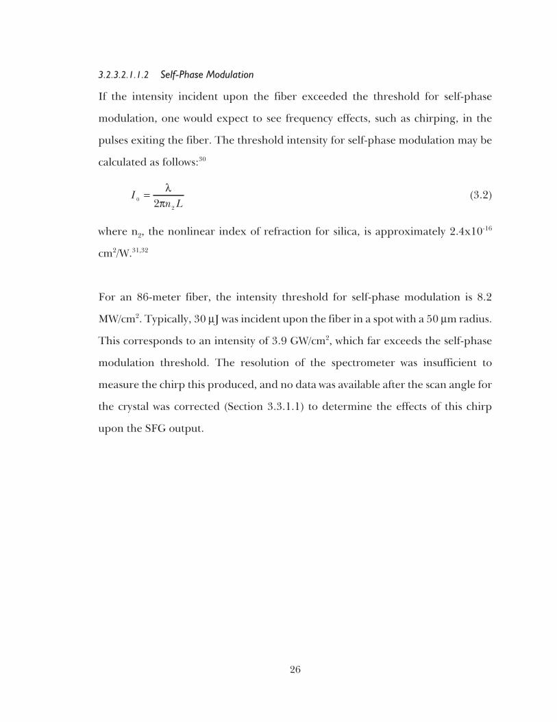
3.2.3.2.1.1.2 Self-Phase Modulation
If the intensity incident upon the fiber exceeded the threshold for self-phase
modulation, one would expect to see frequency effects, such as chirping, in the
pulses exiting the fiber. The threshold intensity for self-phase modulation may be
calculated as follows:30
In L0
22= λ
π(3.2)
where n2, the nonlinear index of refraction for silica, is approximately 2.4x10⁻¹⁶
cm2/W.31,32
For an 86-meter fiber, the intensity threshold for self-phase modulation is 8.2
MW/cm2. Typically, 30 µJ was incident upon the fiber in a spot with a 50 µm radius.
This corresponds to an intensity of 3.9 GW/cm2, which far exceeds the self-phase
modulation threshold. The resolution of the spectrometer was insufficient to
measure the chirp this produced, and no data was available after the scan angle for
the crystal was corrected (Section 3.3.1.1) to determine the effects of this chirp
upon the SFG output.
26

3.2.3.2.1.2 Coupling Lens Selection
Two lenses were needed for coupling the Nd:YAG pulses to the optical fiber.
Traditionally, this coupling is performed using short focal length lenses or
microscope objectives.33 These methods are employed in order to properly launch
the light into the fiber, which consists of two layers of glass, such as doped silica.
The critical parameters are the angle at which the light enters the fiber and its
position on the tip of the fiber, and the efficiency of the coupling is very sensitive to
both. A significant decrease in the coupling efficiency may occur with a 10 to 20 µm
change in the position of the beam on the fiber or a 2 to 5 degree change in the
incident angle.34 Short focal length lenses are therefore typically used to provide
better control over both the position and the angle of the input light.
The problem with using short focal length lenses for this project is that, due to the
small spot size produced, the intensity delivered to the fiber would far exceed its
damage threshold. To determine the spot size produced on the fiber by the short
focal length lenses, the non-Gaussian beam profile of the Nd:YAG laser must be
accounted for. The deviation of the beam from a Gaussian profile is described by
M2, equal to 2.5 for this laser.35 The spot size, wo, was calculated as shown below.36
wM fD
mo = =2
342λ
πµ. (3.3)
f mm D cm m M= = = =25 125 1064 2, . , . ,λ µ 2.5 (3.4)
A standard lens with a focal length of 401 mm was chosen to focus the pulses on the
tip of the fiber - producing a spot size of approximately 135 µm.
27

The light exiting the fiber quickly diffracts, necessitating a short focal-length lens
to collect it. The theoretical angle of diffraction may be calculated using the fiber’s
numerical aperture. The numerical aperture for the fiber is defined using the
difference in refractive index between the core and the cladding,
NA nn n
n=
−
1
1
2
2
2
1
222
(3.5)
where n1 is the refractive index of the core and n2 is the refractive index of the
cladding that surrounds the core.37 The numerical aperture can also be expressed
as the sine of the acceptance angle of the fiber.38 For WF-L22-201 graded index
multimode fiber from Wave Optics, Inc., the numerical aperture is 0.22.39 The exit
angle of the fiber is ( )θ = =−sin .1 022 12.7o. Using a HeNe laser, a ruler, and a white
screen, , the diffraction angle was measured as 11.8 o o±03. . A standard lens with a
one-inch focal length was chosen to collect the light exiting the fiber.
3.2.3.2.1.3 Alternate Delay Design
The optical fiber was originally chosen as a less expensive and time-consuming
method of achieving the necessary delay for the Nd:YAG pulses. The drawback to
this method was that it severely limited the 1 µm power incident upon the crystal.
Other options, which would have allowed a much greater input power, was to create
an optical delay using mirrors. One such design uses two curved mirrors that can be
configured on the same axis to create a lissajous pattern40 or off-axis for a tighter
pattern requiring less space.41 Another design uses one flat mirror and curved
mirror.42 In either case, the light enters and exits the cavity through a hole in one of
the mirrors, and the number of passes within the cavity is set by the angle at which
the light enters, the curvature of the mirrors, and their spacing.
28

3.2.3.2.2 Focusing Lens
The lens used to focus the Nd:YAG pulses on the crystal was chosen to deliver an
intensity of 500 MW/cm2 to the crystal - approximately half the damage threshold
quoted by the manufacturer for 100 ps pulses.
3.2.3.2.3 Optical Delay Line
The purpose of the optical delay line was to provide a fine adjustment of the delay
between the Nd:YAG and CO2 pulses. The line consisted of four mirrors, two of
which were on a translational stage, allowing the length of the delay path to change
(1 mm = 3.33 ps). The mirrors were gold-coated, reflecting both 1 µm and visible
light for alignment purposes.
3.2.3.3 Beam Combiner
For collinear phase matching, the Nd:YAG and CO2 pulses must overlap spatially
as well as temporally. To achieve this, ZnSe was used as a beam combiner. One side
of the ZnSe was coated to reflect 10 µm light with 98.5% efficiency and the material
transmitted 1 µm light with 75 7% %± efficiency (as measured experimentally).
3.2.3.4 Detection Systems
Three types of detection were used in this phase: a photodetector, an energy meter,
and a CCD careful aligned at the output of a spectrometer. The photodetector
provided relative power measurements for purposes of determining alignment and
efficiency. The energy meter provided absolute energy measurements, used to
verify that the laser power was below the crystal’s surface damage threshold. The
spectrometer provided frequency analysis of the crystal output. This spectral
information was mapped spatially and collected using a CCD.
29

3.2.4 Experimental Data
3.2.4.1 Beam Profile Measurement
To ensure that the Nd:YAG pulses were properly collected after exiting the optical
fiber, the beam profile was measured using a micrometer and photodiode. The
photodiode was stepped through the beam and a number of data points were
collected at each position.
30
Beam Profile Measurement
0
100
200
300
400
500
600
700
800
900
1000
1100
1200
1300
12 13 14 15 16 17 18 19 20 21 22 23 24 25
Distance (mm)
Inte
nsit
y(m
V)
Figure 3-6: Beam Profile Data

The profile was also examined using a Cohu camera. The figure below shows the
image of the beam, with its horizontal (left) and vertical (right) profiles below.
31
Figure 3-7: Image of Nd:YAG Pulse

3.2.4.2 Pulse Synchronization
The Nd:YAG (bottom trace) and CO2 pulses (top trace) were temporally aligned, as
shown in the following figures.
32
10 m pulses,1 div = 4 ns
µ
Nd:YAG pulse
Figure 3-9: Nd:YAG and a Single CO2 Pulse
10 m pulses,1 div = 100 ns
µ
Nd:YAG pulse
Figure 3-8: Nd:YAG Pulse and CO2 Pulse Train

3.2.4.3 SFG in AgGaS2
3.2.4.3.1 Efficiency of Coupling to Optical Fiber
The maximum efficiency of the coupling to the optical fiber was measured as 19% ±
6% using a photodiode. The average coupling efficiency for measurements was
15%, and the efficiency was remeasured for each set of data to verify that the
alignment had not drifted.
3.2.4.3.2 Efficiency of SFG
The combined efficiency of the SFG interactions was estimated as 0.4% ± 0.03%,
using a photodiode and calculating ηµ
≈+P P
Pnm nm
m
967 964
1
. By this estimation, each
interaction (10.59 µm + 1.06 µm → 966 nm or 10.27 µm + 1.06 µm → 964 nm)
would have an efficiency slightly less than 0.2%, which is in agreement with the
theoretical calculations in Section 3.1.3.
3.2.4.3.3 Spectral Data
The output of the AgGaS2 crystal was also viewed with a CCD at the output of the
spectrometer, for purposes of determining the frequency of the outputs and for
detecting the modulation (Section 3.2.4.4). Figure 3-10 shows the spectrometer
output, and Figure 3-11 is a plot of one line of spectrometer data. A grating with
1200 grooves/mm was used with a 64 µm slit.
33

34
967 nm(from 10.6 µm SFG)
964 nm(from 10.3 µm SFG)
Figure 3-11: One Line of Spectrometer Data, AgGaS2 Output
967 nm(10.6 m)µ
964 nm(10.3 m)µ
Figure 3-10: Spectrometer Image of AgGaS2 Output

3.2.4.4 Detection of Modulation
The first phase was designed with sufficient power to accommodate one
upconversion, and the modulation was to be analyzed spectrally. No spectral effects
of the 1 THz modulation were detected in the output of the AgGaS2 crystal.
3.3 Phase 2: SFG Using 100 ps CO2 Pulses
A second phase of the experiment was constructed in order to provide sufficient
power to try other methods of detecting the 1 THz modulation (Sections 4, 5). Two
experimental setups were used, since the first did not provide scanning of the
phase matching angle. (Section 3.3.1.1) The scanning of this angle is necessary to
measure the acceptance angle (Figures 2-7, 3-1).
3.3.1 Experimental Setup
The longer, 100 ps CO2 pulse was used for this experiment, instead of the short
pulse train (Figure 1-3). The need for the fiber optic delay line was eliminated by
not using the second stage of amplification of the CO2 pulses, and, thus, the limits
on the 1 µm power imposed by the damage threshold of the fiber were exchanged
for the higher damage threshold of AgGaS2. A bandpass filter centered at 970 nm
with a FWHM of 10 nm was used to prevent any residual 1 or 10 µm power
transmitted by AgGaS2 from reaching the KDP crystal.
35

3.3.1.1 Crystal Orientation
When the AgGaS2 crystal was received by the lab, no documentation was present to
indicate the orientation of the crystal’s optical axis. During the first and second
phases of the project, the crystal’s orientation was determined by the efficiency of
SFG - i.e., the crystal was rotated until the face yielding the highest efficiency was
found. Since the incident polarization was ordinary in each setup, each
experienced the same Type I ooe SFG interaction with the same output
wavelengths and the same efficiency; however, the position of the stage in the first
setup did not allow the phase matching angle to be scanned. Once the rotational
stage was correctly positioned, the acceptance angle was measured. (Figure 3-16)
36
RegenAmplifier
30% BeamSplitter Phase 1 Setup
Variable1 mAttenuatorµ
OD 2.0Attenuator
ZnSe AgGaS2
ShortFL Lens
Spectrometer
Si Mirror
Co pulsesfrom masteroscillator
2
Computer
CCDCamera
970 nmFilter
KDP
Figure 3-12: Phase 2: First Experimental Setup

37
Figure 3-14: Photo of Second Setup for Phase 2
z, o
ptic
al a
xis
Input polarizationrotation ofcrystal stage
θ
First Setup
θ and rotationof crystal stage
Second Setup
z, o
ptic
al a
xis
Input polarization
Figure 3-13: Crystal Orientation for Phase Matching Angle Scan

3.3.2 Theoretical Efficiency and Output Power
The purpose of this setup was to provide a higher output power - which differs from
the efficiency of the nonlinear interaction. The power of the output wave is
controlled by the amount of the medium used (length and area) and by the
intensity of the incident waves; thus, an interaction with a lower efficiency may still
yield a high output power if the interaction area is large or the crystal is long and
the incident waves have high powers.
The primary difference between this setup and the previous one is that this setup
used unfocused beams to interact within the crystal; whereas, the first setup used
focused beams. To develop a permanent system, one would have to optimize the
output power of the crystal by testing both the focused and unfocused geometries.
Measurements indicate that Phase 1 delivered 0.04 MW (4 µJ) of 1 µm light to the
crystal, whereas Phase 2 delivered 100 MW (10 mJ). The efficiency of the
interaction in Phase 2 was calculated as 0.0091% for 10.27 µm and for 10.59 µm.
Regardless of having 15 times less efficiency, the output power of the crystal for
Phase 2 was theoretically predicted to be 100 times greater than that for Phase 1.
This would provide sufficient output power to up-convert the 964 and 967 nm
light in KDP. (Section 4)
38

3.3.3 Experimental Data
Two sets of data were taken - one to verify that the output intensity varied linearly
with the input energy (using the first setup) and the other to examine sinc2 function
in the intensity profiles of the 964 and 967 nm light (using the second setup). The
intensity in the 967 nm wave varied linearly with the input energy.
39
AgGaS2: Variation of 967 nm Intensity with 1µm Energy
0
100
200
300
400
500
600
700
0 0.02 0.04 0.06 0.08 0.1 0.12 0.14 0.16
Energy (mJ)
SFG
Inte
nsit
y(m
V)
Figure 3-15: AgGaS2 Output Intensity Variation with 1 µm Input Energy

3.3.3.1 Non-Collinear Phase Matching in AgGaS2
SFG was also achieved in the AgGaS2 crystal using non-collinear phase matching.
This layout eliminated the need for the ZnSe beam combiner, which made the
crystal’s surface damage threshold the limiting factor in the system. Previously the
power level in the system was determined by first the damage threshold of the
optical fiber and second by that of the ZnSe.
40
Phase Matching Curves for SFG in AgGaS2
0
0.1
0.2
0.3
0.4
0.5
0.6
0.7
0.8
0.9
1
0 0.25 0.5 0.75 1 1.25 1.5 1.75 2 2.25 2.5 2.75 3 3.25 3.5 3.75 4
External Angle (degrees)
Nor
mal
ized
Ave
rage
Inte
nsit
y(a
rbit
rary
unit
s)
964 nm fit
967 nm fit
964 nm data
967 nm data
Figure 3-16: Angular Dependence of SFG Output in AgGaS2

The non-collinear phase matching setup, Figure 3-17, was used to measure the
efficiency of SFG and the SFG output data for Figure 3-16. The efficiency of the
interaction was also measured, Section 3.3.3.1.1.
3.3.3.1.1 Efficiency: Non-Collinear Phase Matching
The efficiency of this setup was measured using a silicon photodiode, as follows:
Background = 20 mV
1 µm pulses: 159 mV with 106 attenuation
SFG output of (10.59 µm + 1.04 µm = 967 nm): 62 mV with 104 attenuation
This efficiency is roughly 0.3%, neglecting the CO2 input, and is consistent with the
efficiencies measured in the first phase (~0.12%) and the theoretically predicted
efficiency (~0.2%). This demonstrated that the noncollinear setup produces
equivalent results as that which include the ZnSe beam combiner.
41
λ/2
Attenuators
AgGaS2
Si Mirror
Co pulsesfrom masteroscillator
2
970 nm Filter& photodetector
1 m pulsesµ
Mirrorwith hole
Figure 3-17: Non-Collinear Phase Matching, Experimental Setup

3.4 Summary
The results from this study included the characterization of SFG in AgGaS2, as well
as much experience working with the crystal. Detecting the 1 THz modulation
proved to be more difficult than originally expected and provided the motivation
for the autocorrelator (Section 5.3). Conclusions from this work included:
In AgGaS2, the phase matching curves for generating 967 and 964 nm lightby SFG are sufficiently overlapped that the interactions can besimultaneously phase matched.
The proper orientation of the optical axis of an unknown crystal and,subsequently, the angles through which all rotational stage scan, should notbe determined by only using the efficiency of a nonlinear interaction, but byan angle dependent measurement, such as scanning the SFG output.
SFG in the short crystal may be achieved by either collinear or noncollinearphase matching, with similar output powers. Using noncollinear phasematching avoids the use of a beam combiner with a damage threshold lowerthan that of the crystal, allowing for higher input powers.
42

4 UP-CONVERSION IN KDP
In order for the 1 THz modulation to exist, the three waves incident on the AgGaS2
crystal must be simultaneous in both time and space. To confirm this, the light
resulting from SFG in the AgGaS2 was up-converted using a KDP crystal. If the
waves resulting from SFG in AgGaS2 are spatially and temporally simultaneous,
then the up-conversion in KDP results in three waves43: 483.4 nm (SHG of 967 nm),
482.7 nm (SFG of 967 nm and 964 nm), and 482.0 nm (SHG of 964 nm).
4.1 Theoretical Analysis
The KDP crystal is transparent to wavelengths between 0.178 and 1.45 µm,2 which
makes it suitable for the second up-conversion. In addition, the phase matching
angles for the interactions of interest are sufficiently similar and within the
acceptance angles to make phase matching of more than one interaction feasible.
(e.g., SFG of 1 µm and 967 nm as well as SFG of 1 µm and 964 nm). The group
velocity mismatch (GVM) between the 964 nm pulses and the SHG output, 482 nm,
is 0.8 ps/cm - small enough to maintain the 1 THz modulation over the length of
the crystal. (Refer to Section 3.1 for more details.)
43

4.2 Experimental Data
The diagram for the setup is provided in Figure 3-11. The three output waves were
detected using the spectrometer and CCD camera, using a 1200 grooves/mm
grating and a 64 µm slit. The difference in output power was theoretically
predicted, with the efficiency of SFG between 964 ad 967 nm four times that for
SHG of either. This difference was verified experimentally, where the output
power of SFG was 3 to 4 times that of the SHG. From these results, it was inferred
that the second stage of up-conversion (Figure 1-1) would use SFG, instead of SHG
- most likely SFG of the 1 µm pulses and the output of the AgGaS2 crystal.
44
1 cm crystal
8 mm spot size
Phase Matching
Angle (deg., int)
Acceptance Angle
(deg., int)% Efficiency
SHG ,1 µm 41.208 0.0631 5.6E-07
SHG, 967 nm 41.411 0.0564 1.9E-09
SHG, 964 nm 41.432 0.0562 1.9E-09
SFG: 964 & 967 nm 41.421 0.0563 3.9E-09
SFG: 1 µm & 967 nm 41.186 0.0596 1.2E-06
SFG: 1 µm & 964 nm 41.120 0.0595 1.2E-06
Table 4-1: Theoretical Parameters for SHG, SFG in KDP

This particular setup used a long CO2 pulse which was gated by the 1 µm pulse;
however, in the future, the up-conversion of the 964 and 967 nm outputs in KDP
could be used to demonstrate that the pulses incident upon the AgGaS2 crystal and
spatially and temporally simultaneous.
45
SHG SFG SHG
483.4nm
482.7nm
482nm
Figure 4-1: Up-Conversion in KDP, Image
Up-Conversion in KDP: Spectrometer Data
1000
1100
1200
1300
1400
1500
1600
1700
0 20 40 60 80 100 120 140 160 180 200
Column Number
Inte
nsit
y SHG:482 nm
SHG:483.4 nm
SFG:482.7 nm
Figure 4-2: Upconversion in KDP, Data

5 DETECTION OF MODULATION: AUTOCORRELATION
The purpose of an autocorrelator is to spatially map the temporal structure of a
laser pulse. This is accomplished by splitting the pulse into two paths, delaying one
of them, and recombining the paths through noncollinear phase matching in a
nonlinear crystal, such as KDP. The first autocorrelator used in the experiment was
built by Positive Light (Section 5.2). When this autocorrelator proved to not work
for dual frequency detections, a second autocorrelator was designed and built.
(Section 5.3) This will be used in future work on this project, in either a single-shot
or a multi-shot mode. (Section 5.4)
5.1 Background
An autocorrelator is used to examine the temporal structure of the laser pulse,
using the intensity autocorrelation function, below.44
( ) ( ) ( )Autocorrelation A I t I t dt= = +−∞
∞
∫τ τ (5.1)
Two types of autocorrelators have been considered for this project - single shot and
multi-shot. Each uses a nonlinear crystal to provide the autocorrelation signal, by
SHG of the pulse with a shifted version of itself. The difference between the
multi-shot and single-shot configurations is the way in which the autocorrelation
signal is measured.
In the multi-shot configuration, the autocorrelation signal is measured by scanning
the shifted pulse through the original pulse, using an interferometer. The delay,
∆τ, is provided by the scanning mirror, such that ∆τ = 2dc
, where d is the diameter
46

of the mirror and c is the speed of light. This setup requires that the pulse
repetition rate be much greater than the scan rate.36 The resulting autocorrelation
trace can be measured in many ways, such as by a CCD45 or photomultiplier46.
In a single-shot autocorrelator, the autocorrelation function is measured once per
shot, using the spatial pattern resulting from noncollinear SHG of the pulse and
the shifted version of itself. Physically, the time delay between the two pulses is
different at every point in the crystal. When the light resulting from noncollinear
SHG at each point is measured, the effect is to provide “integration” of the incident
pulses similar to that which is obtained by scanning in multi-shot systems.36,47
When the result of noncollinear SHG is measured, the width of the pulse, ∆w,
corresponds to a specific amount of time, ∆τ. These quantities are related by the
crystal’s index of refraction at the incident wavelength, n, the speed of light, c, and
the angle between the two incident pulses, 2θ, as:48
∆ ∆w
cn
= τθsin
(5.2)
When designing a single shot autocorrelator, one must keep the detector close to
the crystal to avoid destructive interference 40, and use a beam diameter that is at
least 2/3 larger than the length of the pulse within the crystal, c nτ .40,49
47

5.2 Commercial Autocorrelator
The first single-shot autocorrelator used was made by Positive Light. This
autocorrelator has two modes, differing by one component in the path used to
delay one part of the pulse. One setup uses a mirror to measure fempto-second
pulses (Model SSA-F) and the other uses a grating to measure picosecond pulses
(Model SSA-P).50 Since the modulation in this project should vary on the order of 1
ps, the SSA-P model was used. The autocorrelator was used in place of the
spectrometer, as in the figure below.
The operation of the autocorrelator was tested using the Nd:YAG pulse (without
the AgGaS2 crystal). The oscilloscope traces below show the two collinear SHG
pulses (1.064 µm -> 532 nm), and the noncollinear SHG pulse. These were
obtained by rotating the KDP crystal in the SSA-P autocorrelator - adjusting the
48
RegenAmplifier
30% BeamSplitter Phase 1 Setup
Variable1 mAttenuatorµ
OD 2.0Attenuator
ZnSe AgGaS2
Si Mirror
Co pulsesfrom masteroscillator
2
970 nmFilter
Autocorrelator
Figure 5-1: Experimental Setup for Autocorrelation

phase matching angle for first one collinear SHG pulse, next for the noncollinear
SHG pulse, then the other collinear SHG pulse. The structure in the traces is due to
the beam profile of the Nd:YAG laser. 1 MΩ termination on the oscilloscope was
required to read data from the CCD. The 100 ps Nd:YAG pulse was too long to be
used for characterizing the autocorrelator, but this procedure demonstrated how
one would verify the device’s operation in the future.
49
Figure 5-2: Collinear SHG in SSA with 1 µm Pulse, Path 1
Figure 5-3: Noncollinear SHG with two 1 µm Pulses

Two problems arose when this autocorrelator was used to detect the 1 THz modulation:
1) The result of up-converting the output of the AgGaS2 crystal in KDP wassufficiently strong to be detected using a CCD, but not a photodiode.
2) In a different experiment performed by our lab group, it was discoveredthat the grating spatially separated the incident wavelengths. Since thesewavelengths must be spatially and temporally overlapped to maintain the 1THz modulation, the SSA-P model would not be suitable for detecting themodulation in the output of the AgGaS2 crystal.
5.3 Custom Autocorrelator Design
A custom autocorrelator was redesigned, from an older setup, and tested; however,
due to time constraints, the output of the AgGaS2 crystal was not measured using
this autocorrelator.
50
Figure 5-4: Collinear SHG in SSA with 1 µm Pulse, Path 2

5.3.1 Experimental Setup
51
Figure 5-6: Photo of Custom Autocorrelator
50% BeamSplitter
KDP
Input
101 mm FLCylindricalLenses
Noncollinear SHG
AdjustableDelay
Figure 5-5: Block Diagram of Custom Autocorrelator

5.3.2 Experimental Design
The custom autocorrelator was designed using non-dispersive elements and a 2.5
cm KDP crystal. Two cylindrical lenses with 10 cm focal lengths were used to focus
the pulses to a line, in order to increase their intensity. A line was used instead of a
point to preserve the width of the beams (Section 5.1). The 2.5 cm KDP crystal was
used because it had a sufficiently large aperture to accommodate the widths of the
incident pulses.
To calculate the width of the autocorrelation window, the intersection angle
between the pulses was measured - 22.6o. (θ = 11.3o, external to the crystal) This
corresponds to an internal angle of 7.6o (by dividing the external angle by no = 1.49
for 1 µm in KDP). Using this angle, a beam width of 8 mm corresponds to an
autocorrelation window of 5.25 ps. For an 8 mm-wide beam, this corresponds to a
resolution of approximately 0.6 ps/mm at the CCD. This should be sufficient to
detect the 1 ps beatwave modulation.
5.3.3 Future Work
The custom autocorrelator has been built and tested. For detection of the 1 THz
pulses, it can be used as either a “single-shot” or “multi-shot” autocorrelator. The
single-shot autocorrelation scheme is preferable - since the modulation is detected
using one laser pulse, the measurement errors are less. If there is insufficient power
to detect the output on a CCD, a “multi-shot” configuration can be created by
replacing the CCD with a photodiode. The laser pulses incident on the KDP crystal
would then be scanned through each other manually, using the micrometer on the
delay line. The data would be the average intensity of noncollinear SHG at each
point, as measured by the photodiode.
52

6 CONCLUSION
This project accomplished some of its original goals by realizing two stages of
up-conversion - in AgGaS2 and KDP - and established an experimental
configuration for up-converting the THz modulation in nonlinear crystals. A clear
path has been left for future work - including an operating autocorrelator for use
with a 6 ps Nd:YAG pulse. (Section 5)
53

7 REFERENCES
1 Clayton, C., et al. “Second Generation Beatwave Experiments at UCLA”.
Nuclear Instruments & Methods in Physics Research, Section A. Vol 410, No 3.
pp 378-387. 1998.
2 Lal, A. et al. “Measurement of the Beatwave Dynamics in Time and Space”.
Proceedings of the 1995 Particle Accelerator Conference. Vol 2, No 5. pp 767-769.
3 Hankla, A.K. et al. “Tunable Short-Pulse Beat-wave Laser Source Operating at
1 mm”. Optics Letters. Vol 22, No 22. pp 1713-1715. November, 1997.
4 Tochitsky, S. Y., et al. “Generation of 160-ps Terawatt-Power CO2 Laser
Pulses”. Optics Letters. Vol 24, No 23. pp 1717-1719. 1999.
5 Dmitriev, V.G., G.G. Gurzadyan, and D.N. Nikogosyan, eds. Handbook of
Nonlinear Optical Crystals. 3rd ed. Berlin: Springer-Verlag, 1999.
6 Shen Y.R. The Principles of Nonlinear Optics. New York: John Wiley & Sons,
Inc., 1984.
7 Sauter, E.G., Nonlinear Optics. New York: John Wiley & Sons, Inc., 1996.
8 Lauberau, Alfred. “Optical Nonlinearities with Ultrashort Pulses”. Topics in
Applied Physics: Ultrashort Laser Pulses. Vol 60. Ed. W. Kaiser.New York:
Springer-Verlag, 1993.
54

9 Glenn, W.H. “Second-Harmonic Generation by Picosecond Optical Pulses”.
IEEE Journal of Quantum Electronics. Vol QE-5, No 6. pp 284-290. 1969.
10 Bhar, G.C., S. Das, and P.K. Datta. “Tangentially phase-matched infrared
detection in AgGaS2”. Journal of Physics D: Applied Physics. Vol 27. pp.
228-230. 1994.
11 Voronin, E.S. et al. “Conversion of Infrared Radiation in an AgGaS2 Crystal”.
Soviet Journal of Quantum Electronics. Vol 5, No 5. pp 597-598. 1975.
12 Bhar, G.C., et al. “Synchronous and Noncollinear Infrared Upconversion in
AgGaS2”. Applied Physics Letters. Vol 54, No 16. pp 1489-1491. 1989.
13 Boyd, G.D., H. Kasper, and J.H. McFee. “Linear and Nonlinear Optical
Properties of AgGaS2, CuGaS2, and CuInS2, and Theory of the Wedge
Technique for the Measurement of Nonlinear Coefficients”. IEEE Journal of
Quantum Electronics. Vol QE-7, No 12. pp. 563-573. December, 1971.
14 McEwan, K.J. “High-power Synchronously Pumped AgGaS2 Optical
Parametric Oscillator”. Optics Letters. Vol 23, No 9. pp 667-669. May, 1998.
15 Roberts, D.A. “Simplified Characterization of Uniaxial and Biaxial Nonlinear
Optical Crystals: A Plea for Standardization of Nomenclature and
Conventions”. IEEE Journal of Quantum Electronics. Vol 28, No 10. pp
2057-2074. October, 1992.
55

16 Cleveland Crystals, material properties table,
http://www.clevelandcrystals.com/AGSSE.shtml#table
17 Zondy, J.J. and D. Touahri. “Updated Thermo-Optic Coefficients of AgGaS2
from Temperature-Tuned Noncritical 3 2ω ω ω− → Infrared Parametric
Amplification”. Journal of the Optical Society of Americ B. Vol 14, No 6. pp
1331-1338. June, 1997.
18 Nikogosyan, D.N. “Nonlinear Optical Crystals (Review and Summary Data)”.
Soviet Journal of Quantum Electronics. Vol 7, No 1. pp 1-12. January, 1977.
19 Fan, Y.X., et al. “AgGaS2 Infrared Parametric Oscillator”. Applied Physics
Letters. Vol 45, No 4. pp 313-315. August, 1984.
20 Bhar, G.C. et al. “Phasematching of Infrared Nonlinear Laser Devices Using
AgGaS2”. IEEE Journal of Quantum Electronics. Vol 24, No 8. pp 1492-1494.
August, 1988.
21 Cheevers, Elizabeth. Corning Optical Fiber Information Center, Private
Communication. February, 2000.
22 Milam, D. “1064-nm Laser Damage Thresholds of Polished Glass Surfaces as a
Function of Pulse Duration and Surface Roughness”. Symposium on Optical
Materials for High Power Lasers. Boulder, Colorado. September 12-14, 1978.
56

23 Milam, D. “Laser Induced Damage at 1064 nm, 125 psec”. Applied Optics, Vol
16 No 5. pp 1204-1208. May, 1977.
24 Jahn, L.A. Gomez, J.J. Kasinski, and R.J. Dwayne Miller. “High-Energy
Handling Capabilities of Optical Fibers: Application to Pulse Compression
and Direct Generation of Megawatt Picosecond Pulses”. Applied Physics A. Vol
43. pp 41-46. 1987.
25 General Fiber Optics, Inc. Catalog, 1985.
26 Rainer, F. E.A. Hildum, and D. Milam. “Database of Average-Power Damage
Thresholds at 1064 nm”. The Boulder Damage Symposium. October 26-28, 1987.
27 Allison, S.W., et al. “Pulsed Laser Damage to Optical Fibers”. Applied Optics.
Vol 24, No 19. pp 3140-3145. October, 1985.
28 Art Photonics, http://www.jtingram.com/art/hipo.html
29 Crow, John D. “Power Handling Capability of Glass Fiber Lightguides”.
Applied Optics. Vol 13, No 3. pp 467-468. 1974.
30 Siegman, Anthony E. Lasers. California: University Science Books. 1986.
31 Kim, K.S. et al. “Measurement of the Nonlinear Index of Silica-Core and
Dispersion-Shifted Fibers”. Optics Letters, Vol 19, No 4. pp 257-260. 1994.
57

32 Boskovic, A. et al. “Direct Continuous-Wave Measurement of n2 in Various
Types of Telecommunications Fiber at 1.55 mm”. Optics Letters, Vol 21, No
24. pp 1966-1967. 1996.
33 Thorlabs Company Catalog, www.thorlabs.com
34 Kawano, K., H. Miyazawa, and O. Mitomi. “New Calculations for Coupling
Laser Diode to Multimode Fiber”. Journal of Lightwave Technology. Vol
LT-4, No 3. pp. 368-374. March, 1985.
35 Continuum technical support. Model number RGA69-10. March, 2000.
36 II-VI, Inc. http://www.iivi.com/pages/res-determining.html
37 Yeh, C. Handbook of Fiber Optics: Theory and Applications. New York:
Academic Press, Inc. 1990.
38 Weik, M.H. Fiber Optics Standard Dictionary, 3rd ed. New York: Chpman &
Hall. 1997.
39 Wave Optics, Inc.
http://www.waveoptics.com/Accessories.html#Accessory_Fiber_Anchor
40 Herriot, D.R. and H.J. Schulte. “Folded Optical Delay Lines”. Applied Optics.
Vol 4, No 8. pp 883-889. August, 1965.
58

41 McManus, J.B., P.L. Kebabian, and M.S. Zahniser. “Astigmatic Mirror
Multipass Absorption Cells for Long-Path-Length Spectroscopy”. Applied
Optics. Vol 34, No 18. pp 3336-3348. June, 1995.
42 Reeder, Robin. “Slab Amplifier Design”. Hughes Aircraft, 1992.
43 Bass, M. et al. “Optical Mixing”. Physical Review Letters. Vol 8, No 1. p 18. 1962.
44 Collier, J. et al. “Uniaxial Single Shot Autocorrelator”. REview of Scientific
Instruments. Vol 70, No 3. pp 1599-1602. 1999.
45 Yasa, Z.A. and N.M. Amer. “A Rapid-Scanning Autocorrelator Scheme for
Continuous Monitoring of Picosecond Laser Pulses”. Optics Communications.
Vol 36, No 2. pp 406-408. 1981.
46 Watanabe, A. et al. “A Rapid-Scanning Interferometric Autocorrelator for
Monitoring Femptosecond Pulses”. Optics Communications. Vol 69, No 5-6.
pp 405-408. 1989.
47 Jansky, J., G. Corradi, and R.N. Gyuzalian. “On a Possibility of Analyzing the
Temporal Characteristics of Short Light Pulses”. Optics Communications. Vol
23, No 3. pp 293-298. 1977.
48 Rempel, C. and W. Rudolph. “Single Shot Autocorrelator for Femptosecond
Pulses”. Experimentelle Technik der Physik. Vol 37. pp 381-385. 1989.
59

49 Kolmeder, C., W. Zinth, and W. Kaiser. “Second Harmonic Beam Analysis: A
Sensitive Technique to Determine the Duration of Single Ultrahort Pulses”.
Optics Communications. Vol 30, No 3. pp 473-457. 1979.
50 User’s Manual for the Positive Light Autocorrelators, Models SSA-P and
SSA-F. www.poslight.com
60
Related Documents