1 Number systems : In general any number N can be represented in the base ( radix ) R as show below : N R = d n R n + d n-1 R n-1 + ……… d 1 R 1 + d 0 R 0 1 - Decimal system ( R= 10 ) : This system uses ( 10 ) symbols ( 0 – 9 ) Ex: N 10 = 2 3 3 2 6 1 8 0 = 2x10 3 + 3 x 10 2 +6x10 1 + 8x10 0 = 2000 + 300 + 60 + 8= 2368 2 - Binary system (R = 2 ) : It uses only two basic symbol ( 0,1 ) . It is the most suitable number system for digital circuits . Ex: N 2 = 1 4 1 3 0 2 0 1 1 0 =1(2) 4 + 1(2) 3 + 0(2) 2 + 0(2) 1 + 1(2) 0 = 16 + 8+0+0+1= ( 25 ) D Ex: 1 3 0 2 0 1 1 0 = 1(2) 3 + 0(2) 2 + 0(2) 1 + 1(2) 0 = 8+0+0+1 = (9) D 3 - Octal system ( R= 8 ) : It uses 8 symbols ( 0- 7 ) Ex : 1 1 7 0 = 1(8) 1 + 7(8) 0 = 8+7 =( 15)D Ex: 7 3 0 2 4 1 5 0 = 7(8) 3 + o(8) 2 + 4(8) 1 +5(8) 0 = 3584 +0 + 32 + 5=( 3621)D 4 - Hexadecimal system ( R =16 )

Welcome message from author
This document is posted to help you gain knowledge. Please leave a comment to let me know what you think about it! Share it to your friends and learn new things together.
Transcript

1
Number systems :
In general any number N can be represented in the base ( radix ) R as show below: NR = dnRn + dn-1 Rn-1 + ……… d1R1 + d0R0
1- Decimal system ( R= 10 ) : This system uses ( 10 ) symbols ( 0 – 9 ) Ex: N10 = 23326180 = 2x10³ + 3 x 10² +6x101 + 8x100 = 2000 + 300 + 60 + 8= 2368
2- Binary system (R = 2 ) : It uses only two basic symbol ( 0,1 ) . It is the most suitable number system for digital
circuits .
Ex: N2 = 1413020110 =1(2)4 + 1(2)3 + 0(2)2 + 0(2)1 + 1(2)0 = 16 + 8+0+0+1= ( 25 ) D
Ex: 13020110 = 1(2)3 + 0(2)2 + 0(2)1+ 1(2)0= 8+0+0+1 = (9)D
3- Octal system ( R= 8 ) : It uses 8 symbols ( 0- 7 )
Ex : 1170 = 1(8)1 + 7(8)0 = 8+7 =( 15)D
Ex: 73024150= 7(8)3 + o(8)2 + 4(8)1 +5(8)0 = 3584 +0 + 32 + 5=( 3621)D
4 - Hexadecimal system ( R =16 ) It uses 16 symbol :
(0,1,2,..…………,9,A,B,C,D,E,F )
Ex: 11A0 = 1(16)1+ A(16)0 = 16+10 =(26)D
Ex:329150 = 3(16)2+ 9(16)1 + 5 (16)0 =768 + 144 + 5 = ( 773)D
2
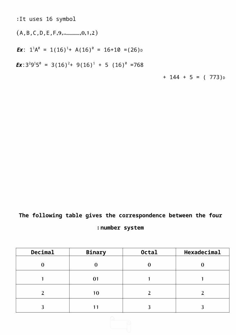
The following table gives the correspondence between the four number system:
Continue the above table.
HexadecimalOctalBinaryDecimal00001101122102331134410045510156611067711178101000891110019A12101010B13101111C110012DEF
101112

3
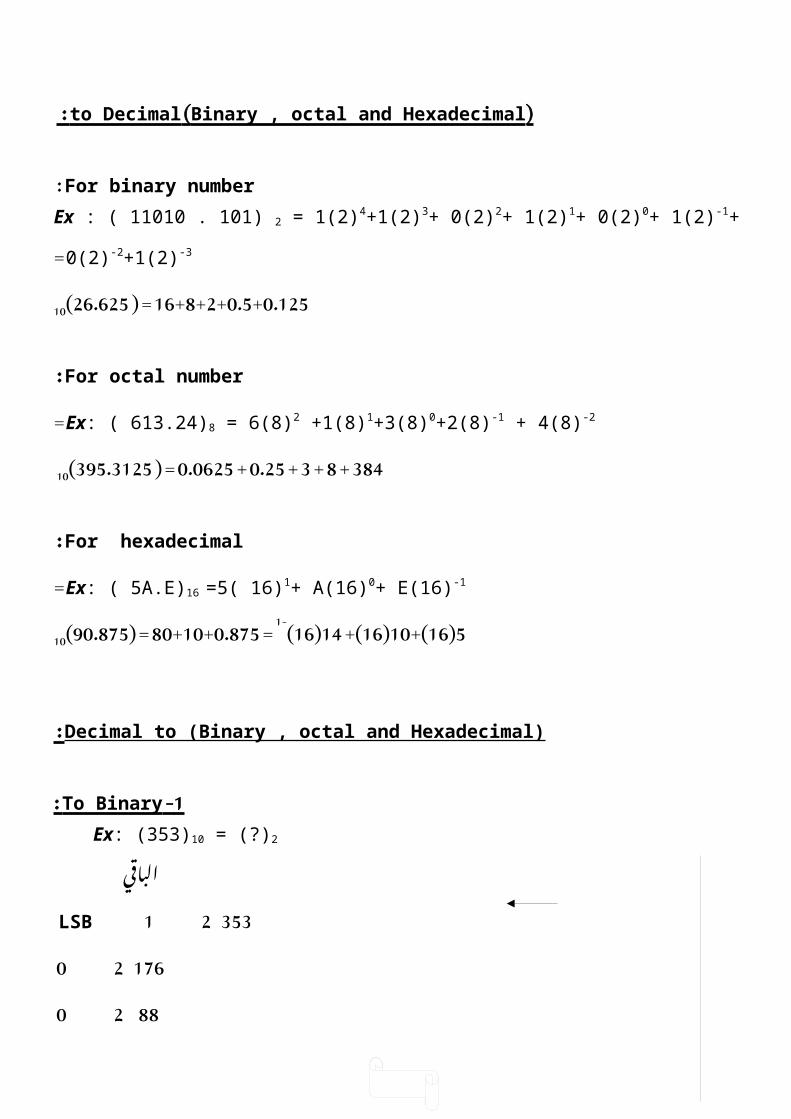
( Binary , octal and Hexadecimal ) to Decimal :
For binary number :Ex : ( 11010 . 101) 2 = 1(2)4+1(2)3+ 0(2)2+ 1(2)1+ 0(2)0+ 1(2)-1+ 0(2)-2+1(2)-3 =
16+8+2+0.5+0.125 ( = 26.625)10
For octal number : Ex: ( 613.24)8 = 6(8)2 +1(8)1+3(8)0+2(8)-1 + 4(8)-2 =
384 + 8 + 3 + 0.25 + 0.0625 ( = 395.3125)10
For hexadecimal : Ex: ( 5A.E)16 =5( 16)1+ A(16)0+ E(16)-1 =
5(16+)10(16 +)14(16)-1 = 80+10+0.875( = 90.875)10
Decimal to (Binary , octal and Hexadecimal) :
1 - To Binary : Ex: (353)10 = (?)2
الباقي 353 2 1 LSB
176 2 0 88 2 0 44 2 0 22 2 0
11 2 1 5 2 1 2 2 0
1 2 1 MSB 0
( 353)10 ( =101100001)2
H.W.: (49302)10 = (?)2
( 10010)10 )?( =2
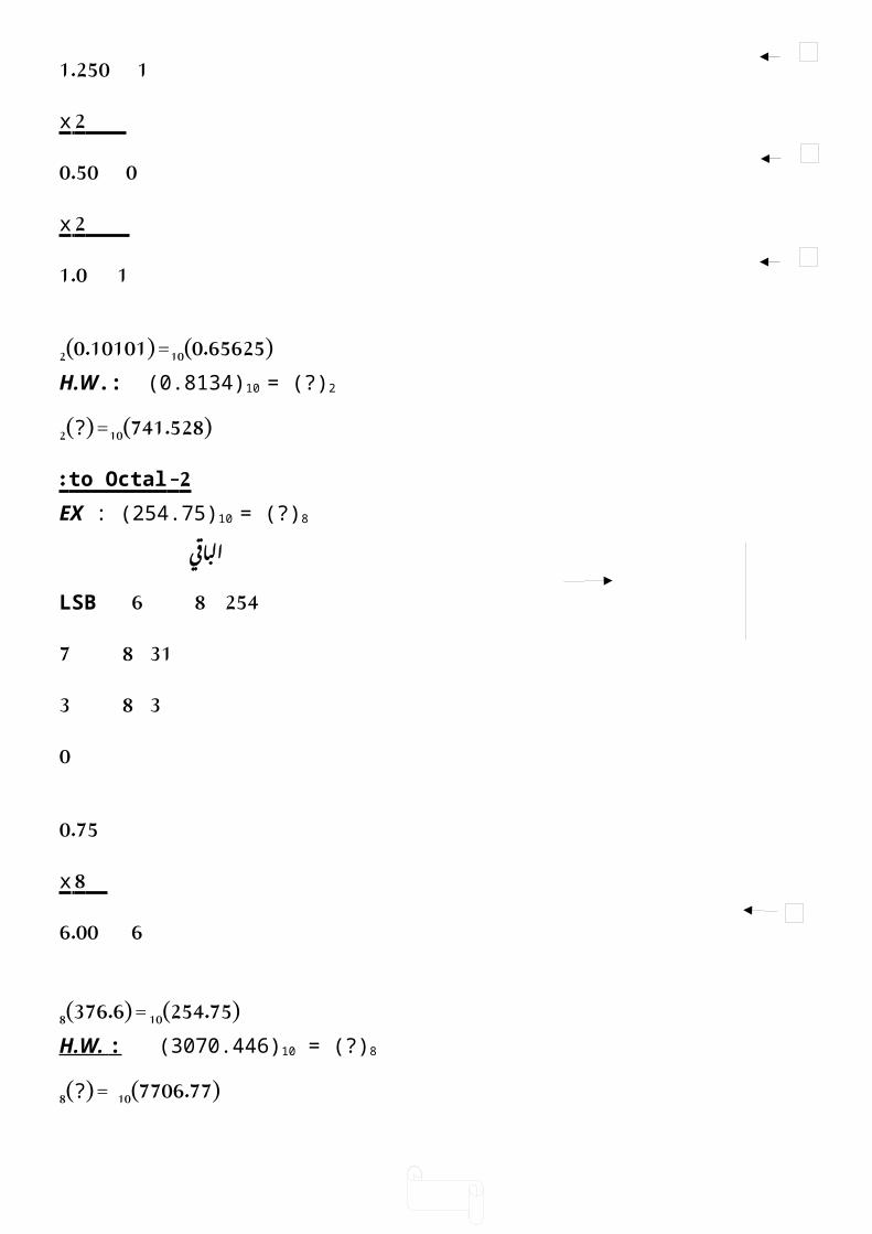
EX: (0.65625)10 = (?)2
0.65625 _____ 2 x
1 1.31250الفارزه بعد مرتبه اول
0.31250
4
_____ 2 x 0 0.62500
_____ 2 x 1 1.250
2 x 0 0.50 2 x
1 1.0
( 0.65625)10 ( =0.10101)2
H.W.: (0.8134)10 = (?)2
( 741.528)10 )?( =2
2 - to Octal : EX : (254.75)10 = (?)8
الباقي 254 8 6 LSB
31 8 7 3 8 3
0
0.75 8 x
6 6.00
( 254.75)10( = 376.6)8
H.W. : (3070.446)10 = (?)8
( 7706.77)10 )?( = 8
3 - to Hexadecimal : EX: (567.1875)10 = (?)16
567 16 7 LSB 35 16 3
2 16 2 0
0.1875 16 x
3 3.0000
( 567.1875)10 ( =237.3)16
H.W. (1005.36)10 = (?)16
( 3987.055)10 )?( =16
Binary , Octal and Hexadecimal conversion(fast method): EX:
1 2 7 5 4 3 Octal 1 0 1 0 1 1 1 1 0 1 1 0 0 0 1 1 Binary

5
A F 6 3 Hexadecimal(= 44899)decimal how!
EX : 2 1 4 4 3 5 Octal
1 0 0 0 1 1 0 0 1 0 0 0 1 1 1 0 1 Binary 1 1 9 1 D Hexadecimal
H.w:(1011100011)B =( ?)0 =(?)H
(AF31C)H= (?)O =(?)B
(37012)0 =)?(B =(?)H
Arithmetic operation : 1-Binary addition : Carry sum 0 + 0 = 0 0 + 1 = 1 1 + 0 = 1 1 + 1 = 1 0
EX: 1 1 1
11 100 111 110 +11 + 10 + 11 +100 110 110 1010 1010
2-Binary subtraction :
0 – 0 = 0 1 – 1 = 0 1 – 0 = 1 10 0 – 1 = 1 with borrow 1
6
EX: 10 10
11 11 101 110 -01 -10 -011 -101 10 01 010 001
3-Binary multiplication : 0 x 0 = 0 0 x 1 = 0 the same manner as in Decimal 1 x 0 = 0 1 x 1 = 1EX: 11 111 X 11 x 101 11 111 + 11 + 000 1001 111
Hexadecimal addition :
EX: 23 58 2B +16 +22 +84 39H 7AH AFH
EX: 1
D F 15D + 12D = 27D 27D -16D = 11D = BH with 1 carry
+A C 18 B 1 + 13D + 10D = 24D 24D – 16D = 8D = 8H with 1 carry
Octal addition :
EX: 14 +23 37o
100011

7
EX: 3 7 7O + 3O = 10D – 8D = 2D = 2O + 1 carry + 5 3 11 2 1 + 3O + 5O = 9D – 8D = 1D = 1O + 1 carry

8
Complements: Complements are used in digital computer for simplifying the subtraction operation and
for logical manipulation . There are two types of complement for each base (R) system:
1-The R´s complement 2-the (R-1)´s complement
For binary number 1´s and 2´s complement For decimal number 9´s and 10´s complement
For octal number 7's and 8's complement For hexadecimal number 15's and 16's complement
The 1 ́ s and 2 ́ s complement : The 1´s complement of a binary number is the no. we get when we change each (0)
to (1) and each (1) to (0) (or subtracting each binary no. from 1 )
EX: 1´s comp. of 1001 0110 1´s comp. of 110010 001101
2´s comp. = 1´s comp. + 1 2´s comp. of 1011 is 0100 + 1 = 0101 2´s comp. of 1110 is 0001 + 1= 0010
Using 2 ́ s complement in subtraction : Instead of subtraction a numbe , we can add it’s2's comp, and disregard the last
carry.EX: decimal
7 111 111 - 5 - 101 1´s 010 2´s 011
2 1 + 1 010 +ve. No.
X carry 011
EX: 13 1101 1101 - 10 1010 1´s 0101 2´s 0110
3 1 + 1 0011 +ve. No.
0110 X carry
EX: 4 100 100 - 7 - 111 1´s 000 2´s 001+
- 3 1 + 101 001 No carry
-ve. No.

9
So 101 100 011
Using 1 ´s complement in subtraction : Instead of subtracting a number we add the 1´s complement of the number , the last carry is then added to the number to get the final answer .
EX: 7 111 111 -5 - 101 1´s 2 carry 1 001 + ve. No. 1 +
010+
010
EX: 3 011 011 - 5 - 101 1´s +010
- 2 101
No carry -ve. No.
101 010
9 ́ s and 10 ´s complements in decimal : The 9´s comp. )similar to the 1´s comp.( is found by subtracting each
decimal digit from 9.
EX: 99 - 25
74 is the 9´s comp. of 25
EX: 9999 - 6291
3708 is the 9´s comp.10´s comp. = 9´s comp. + 1
EX: 74 + 1 =75 is the 10´s comp. of 25
EX: 9.99 - 4.52
5.47 is 9´s comp.

10
7 ́ s and 8 ́ s complements in octal :
7´s = 7 – each digit
8´s = 7´s + 1
EX: 7777 - 2415
is 7´s comp. 5362 + 1
5363 is 8´s comp.
EX: Perform 75268 - 31428 using 8's comp:.
7777 - 3142
EX: 3 011 011 - 5 - 101 1´s +010
- 2 101
No carry -ve. No.
101 010
9 ́ s and 10 ´s complements in decimal : The 9´s comp. )similar to the 1´s comp.( is found by subtracting each
decimal digit from 9.
EX: 99 - 25
74 is the 9´s comp. of 25
EX: 9999 - 6291
3708 is the 9´s comp.10´s comp. = 9´s comp. + 1
EX: 74 + 1 =75 is the 10´s comp. of 25
EX: 9.99 - 4.52
5.47 is 9´s comp.
4635 + 1 = 4636
1 1
7526 + 4636
12 – 8 = 4
11 - 8 = 3
12 - 8 = 4
1 4364 the result
H.W. Perform the following using 8's complement: 5458 – 148 =
67768 – 43378 =

11
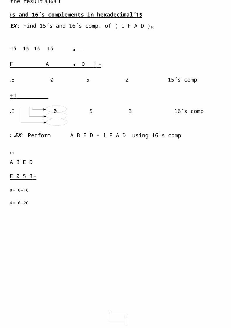
15 ́ s and 16 ́ s complements in hexadecimal : EX: Find 15´s and 16´s comp. of ( 1 F A D )16
15 15 15 15 - 1 F A D
E 0 5 2 15´s comp. 1 +
E 0 5 3 16´s comp.
EX: Perform A B E D – 1 F A D using 16's comp: . 1 1
A B E D + E 0 5 3 16 – 16 = 0 20 – 16 = 4 24 – 16 = 8
1 8 C 4 0 the result
H.W. :Perform the following using 16's complement: F E E D16 – D A F 316 = ANS: 23FA16
9 8 A E16 – 1 F E E16 =

12
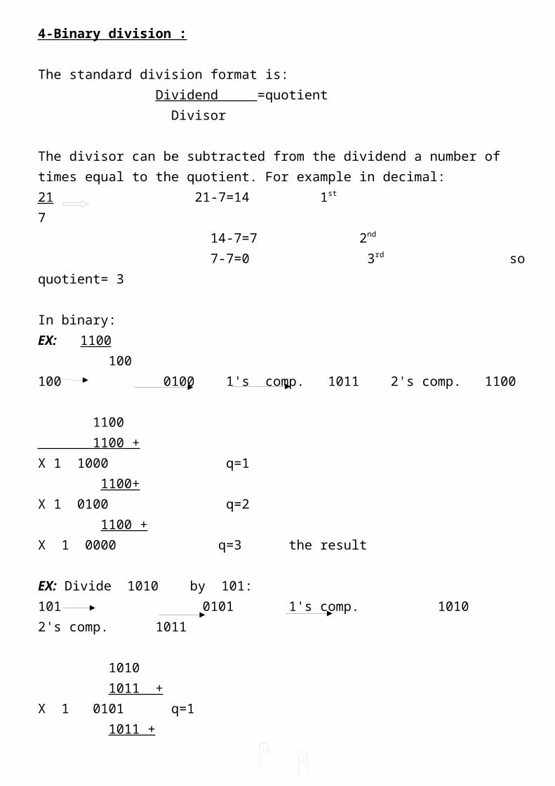
4-Binary division :
The standard division format is: Dividend =quotient Divisor
The divisor can be subtracted from the dividend a number of times equal to the quotient. For example in decimal:21 21-7=14 1st
7 14-7=7 2nd
7-7=0 3rd so quotient= 3
In binary:EX: 1100 100100 0100 1's comp. 1011 2's comp. 1100
1100 1100 + X 1 1000 q=1 1100+ X 1 0100 q=2 1100 +X 1 0000 q=3 the result
EX: Divide 1010 by 101:101 0101 1's comp. 1010 2's comp. 1011
1010 1011 +X 1 0101 q=1 1011 + X 1 0000 q=2 the result

13
Boolean algebra: Boolean variable is a quantity that is either (1) or (0).
Boolean algebra is a mathematical method to manipulate Boolean variable in order
to simplify the Boolean equation.
There are three basic operation in Boolean algebra:
1 -OR (logical addition))+( 2 -AND (logical multiplication)).(
3 -NOT (logical inversion)) (
Gate: It is a device with one output and two or more inputs . output is related to the input
in Boolean (logic) equation.
In the following , the basic logic gates with their symbols , truth table and equation:

14
Gate Symbol Truth table Equation AB Z 00 0
01 1 OR A Z 10 1 Z=A+B
B 11 1
AB Z 00 0 01 0
AND A Z 10 0 Z=A.B B 11 1
A Z
0 1 NOT A Z 1 0 Z=A
AB Z 00 1 01 1
NAND A Z
10 1 Z=A.B B 11 0
AB Z 00 1 01 0
NOR A Z 10 0 Z=A+B B 11 0
AB Z 00 0 01 1
EX_OR A Z 10 1 Z=A + B
B 11 0
AB Z 00 1
01 0 Z=A + BEX_NOR A Z 10 0
B 11 1

15
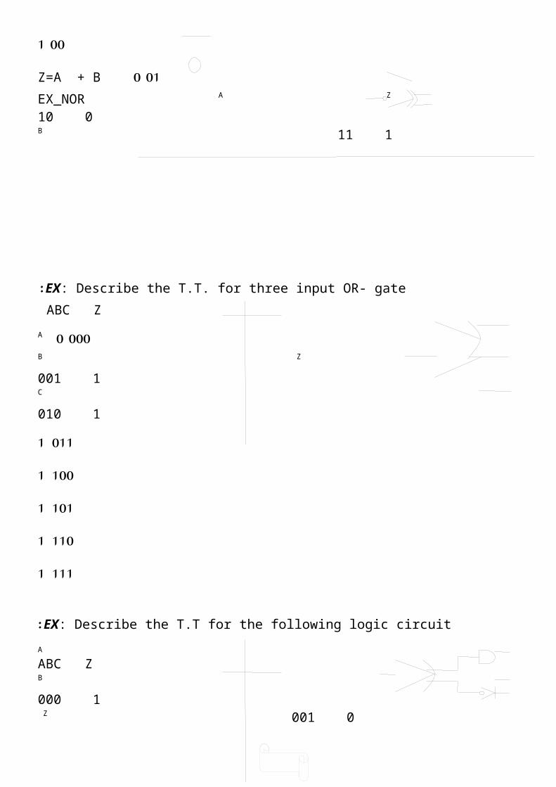
EX: Describe the T.T. for three input OR- gate : ABC Z
000 0 A
B Z 001 1 C 010 1
011 1 100 1 101 1 110 1 111 1
EX: Describe the T.T for the following logic circuit: A ABC Z
B 000 1 Z 001 0
C 010 1 011 0 100 1 101 0 110 1 111 1
H.w.: Describe the T.T for the following :
A
A B
B
Z C Z
c
A A
B B Z
C
Z
D
The basic rules and identities of Boolean algebra:
1 - Identities : a- x.0=0 b- x+0=x c- x.1=x d- x+1=1
e- x.x=x f- x+x=x g- x.x =0 h- x+x=1 i- x=x
16
2- Commutative laws : a- x.y=y.x b- x+y=y+x
3- Associative laws : a- (x+y)+z = x+(y+z) = x+y+z
b- (x.y).z = x.(y.z) = x.y.z
4- Distributive laws : a- x.(y+z) = (x.y)+(x.z) b- x+(y.z) = (x+y).(x+Z)
5- Absorption laws : a- x+x.y = x
b- x+x.y = x+y c- x.(x+y) = x
6- De Morgan ́ s theorem : a- x.y = x+y
b- x+y = x.y
All of these Boolean theorems useful in simplifying a logic expression that is in reducing the no. of terms in the expression.
EX: Prove that A.B = A+B
Sol: A.B = A+B = A+B
EX: Simplify the following: Z=A(A+B)
Sol: Z = AA+AB = A+AB = A
EX: write the Boolean exp. For the following circuit A
B
C Z
Sol: Z = (A+B).C
EX: write the Boolean exp. For the following logic cct: .
17
A
Z
B
Sol : Z = AB+AB = A + B
EX: write Boolean exp. For the following logic cct: .
A
C
Sol: Z = (AB+AB).C =(A + B).C
NOTE : The priorities of logic operation are: ) (
AND OR
EX: Construct the logic circuit for the following Boolean exp : . Z = A.B+B
Sol: We need 2-input AND gate
A B 2-input OR gate
2-inverters Z
EX: Construct the logic cct. , and write the T.T. for the following logic eq. Z = AC+ABC
ABC ZSol: 000 0
A 001 0 C
Z 010 0 011 0
B 100 0 101
1 110
0 111
1
Ex: simplify the following :
A= x y z + x y z + x y z + x y z =x z (y+y) + x z (y+y) = x z +x z = z (x+x) = z
B
Z
B
18
Ex: simplify the following :
Z= AB + A(B+C) + B(B+C) = AB + AB + AC + BB + BC
= AB + AC + B + BC = AB + AC + B = B + AC
Ex: Simplify the following:
Z = ABC + ABC + ABC = ABC + AC(B+B)
= ABC + AC = C (AB+A)
= C (A+B)= CA+CB
Ex: Simplify the following using Boolean Algebra
F= A{ BC(A+B+C+D)} = ABC(A+B+C+D)
= ABCA +ABCB +ABCC +ABCD= ABC+ABC+ABC+ABCD
= ABC+ABCD = ABC(1+D)
= ABC
EX: Simplify :
F = AC + ABC + ACD + CD = A(C+BC) + C(AD+D)
= A(C+B)+C(A+D) = AC + AB + CA +CD = A(C+C) + AB + CD
= A + AB +CD = A(1+B) + CD
= A + CD
EX: Prove that:

19
F= ABC + ABC + ABC = A(B+C) = AC(B+B) + ABC
= AC + ABC = A(C+BC)
= A(C+B)
EX: Simplify:
X = AB + ABC + AB + ABC = AB(1+C) + AB + ABC
= AB + AB + ABC = B + ABC = B + BAC
= B + AC
EX: In a 3-input cct. The output is (1) if the majority of input is (1) , and otherwise , it is zero. White the T.T. for this cct: .
ABC Z 000 0 001 0 010 0 011 1 100 0 101 1 110 1 111 1
Sum -of- product representation of logic function: A SP expression is a product term or several product terms, logically added together
e.g:
F= A.B + ABC + BD.…… +

20
product
( AND)
Derivation of sp: 1-construct the T.T.
2-construct a multiplication column of product of all inputs. 3-the desired expression is the sum of the product of all terms in which the output is
1.
EX: For the following T.T. , write the logic function using sp method:
P terms AB Z 00 1 AB
01 0 AB Z = AB + AB 10 0 AB 11 1 AB
EX: For the following T.T. , write the logic function using sp method , then simplify it:
ABC Z P terms min terms 000 0 ABC m0
ABC m1 001 0 m2 ABC 010 0
011 1 ABC m3 100 0 ABC m4
101 1 ABC m5
110 1 ABC m6
111 1 ABC m7
Z = m3 + m5 + m6 + m7
= ABC + ABC +ABC + ABC = BC(A + A) + ABC + ABC
= BC + ABC + ABC = C(B+BA) +ABC = C(B+A) +ABC = CB + CA + ABC = CB + A(C+BC)
= CB + A(C+B) = CB + AC +AB
Product -of- sum representation of logic function: A PS is a sum term or several sum terms logically multiplied together e.g: .
F = (A+B)(A+B+C)(A+D)..…
Derivation of PS:
21
1-construct the T.T.2-construct a sum column of sum of all inputs ( 0=uncomplement , 1=complement)3-The desired output exp. Is the product of the sum of all terms in which the output
is zero.
EX: For the following T.T. , write the logic function using PS method:
Z S. treams Max terms AB 00 1( A+B )M0
01 0( A+B )M1
10 0( A+B )M2
11 0( A+B )M3
Z= M1 . M2 . M3
( = A+B()A+B()A+B)
EX: Simplify the following function using SP and PS methods:
F(A,B,C) = π( M2 , M3 , M6 )Sol:
ABC Z 000 1 m0
001 1 m1
010 0 M2
011 0 M3
100 1 m4
101 1 m5
110 0 M6
111 1 m7
1-By SP method: Z = m0 + m1 + m4 + m5 + m7
= ABC + ABC + ABC +ABC + ABC = AB(C+C) + AB(C+C) + ABC A
= AB + AB + ABC C
= B(A+A) + ABC B Z
= B + BACZ = B + AC
2 -By PS method : Z = M2.M3.M6
(= A+B+C()A+B+C()A+B+C )(= A+B+C()A+B+C()A+B+C()A+B+C)
(= AA+BA+CA+AB+BB+CB+AC+BC+CC)(= A+BA+CA+AB+B+CB+AC+BC(.)

22
(= A(1+B+C+B+C)+B(1+C+C)(.)(= A+B()AA+BA+CA+AB+BB+CB+AC+BC+CC)
(= A+B()BA+CA+AB+B+CB+AC+BC+C)(= A+B()B(A+A+1+C+C)+C(A+A+1))
(= A+B()B+C ) A
B
z C
PS method require one more gate than SP.
Logic circuit design using NAND and NOR gates only: There are many reasons for using NAND and NOR gates only to implement any logic
function: 1-NAND and NOR gates are simpler, cheaper and have a faster response time to input
changes , and consume less power. 2-The ability to implement any logic function using NAND or NOR gates only is easier
than implement three different logic gates. By using De morgan's theorem we can apply any logic circuit using NAND or NOR gates only.
Using NAND gates: EX: Simplify the following function and implement the final equation using NAND
gates only: H(A,B,C) = Σ (0,1,4,6,7)
H= ABC + ABC + ABC + ABC + ABC
= AB(C+C) + ABC + AB(C+C) = AB + ABC + AB
= B(A+AC) + AB = B(A+C) + AB = BA + BC +AB
B
A
B H
C
A
B
H = H = (AB+BC+AB)

23
( = A B( . )B C( . )AB) = X . Y . Z
Where: X = A B , Y = B C , Z = A B
A
B
B H = X . Y . Z
C
A
B
This cct. is equivalent to the 1st one.
EX: Apply the following function using NAND gates only : F = A + BC
Sol: F = F = (A B C) = (A) . (BC) = A . (BC)
= X . Y
Where X = A Y = BC
A F
B
C
Using NOR gates only: EX: Implement the following function using NOR gates only:
G = (A+B) (A+C) (B+C)
Sol: G = G = (A+B) (A+C) (B+C)( = A+B( + )A+C( + )B+C)
= X + Y + Z
Where X = (A+B) , Y = (A+C) , Z = (B+C)
A X
B
A
C Y G
B Z
C

24
Codes: The binary number is the most natural system , but people are familiar to the decimal
system . one way to solve this conflict is to convert all input decimal numbers into binary numbers and then convert the binary results back to decimal for the human user to understand . However , it is also possible for the computer to perform arithmetic operations directly with decimal numbers provided they are placed in registers in a coded form . When decimal numbers are used for internal arithmetic computations , they are converted to a
binary code with four bits per digit. It is very important to understand difference between the conversion of decimal numbers
into binary and the binary coding for decimal numbers.
BCD ( binary – coded – decimal ): These are codes that combine some of the features of both decimal and binary numbers.
There are different types of BCD codes:
1 - Excess-3 code : It is an important BCD code . To encode decimal number to it’s excess-3 , we add (3) to
each decimal digit before converting to binary:

25
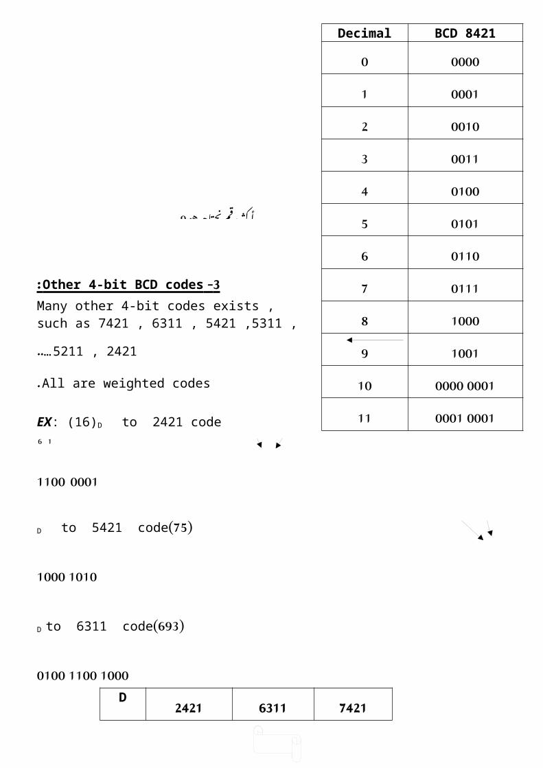
2 - BCD 8421 code : It is weighted code.
3 - Other 4-bit BCD codes : Many other 4-bit codes exists , such as 7421 , 6311 , 5421 ,5311 , 5211 , 2421..…
All are weighted codes.
هو نحتاجه رقم أكثر12
هو نحتاجه رقم أكثر9
Note : It is un weighted code . ex-3Decimal00110010010101201103011141000510016101071011811009
0100 0011100100 010011
BCD 8421Decimal00000000110010200113010040101501106011171000810019
0001 0000100001 000111

26
EX: (16)D to 2421 code 1 6
0001 1100
( 75)D to 5421 code
1010 1000
( 693)D to 6311 code
1000 1100 0100742163112421D0000000000000000100010001100100011001020011010000113010001010100401010111101150110100011006100010011101710011011111081010110011119
53115421Decimal000000000000100011001100102010000113010101004100010005100110016101110107110010118110111009
Gray code: It is un weighted code the main characteristic of this code is that each gray number differs
from the preceding number by single bit.
BinaryGrayDecimal000000000

27
000100011001000112001100103010001104010101115011001016011101007100011008100111019101011111010111110111100101012110110111311101001141111100015
EX: 1 0 1 0 Gray 1 1 0 0 Binary
1 1 0 0 Binary 1 0 1 0 Gray
Alpha numeric codes:
It is an assignment of bit combinations to the letters of the alpha bet , the decimal digit (0-9) , punctuation marks , and several special character such as. #
The most widely used of alpha numeric codes are:
1 -EBCDIC (Extended Binary Coded Decimal Interchange Code ).
2 -ASCII (American Standard Code for Information Interchange ).
The EBCDK code uses 8-bit to represent each symbols while the ASCII code use 7-bit code.
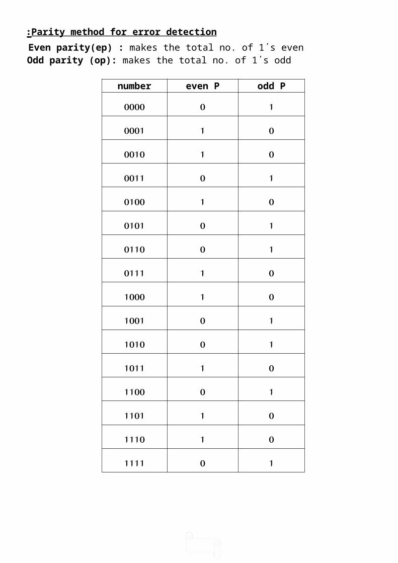
Parity method for error detection: Even parity(ep) : makes the total no. of 1΄s even
Odd parity (op): makes the total no. of 1΄s odd
odd Peven Pnumber100000010001010010

28
100011010100100101100110010111011000101001101010011011101100011101011110101111
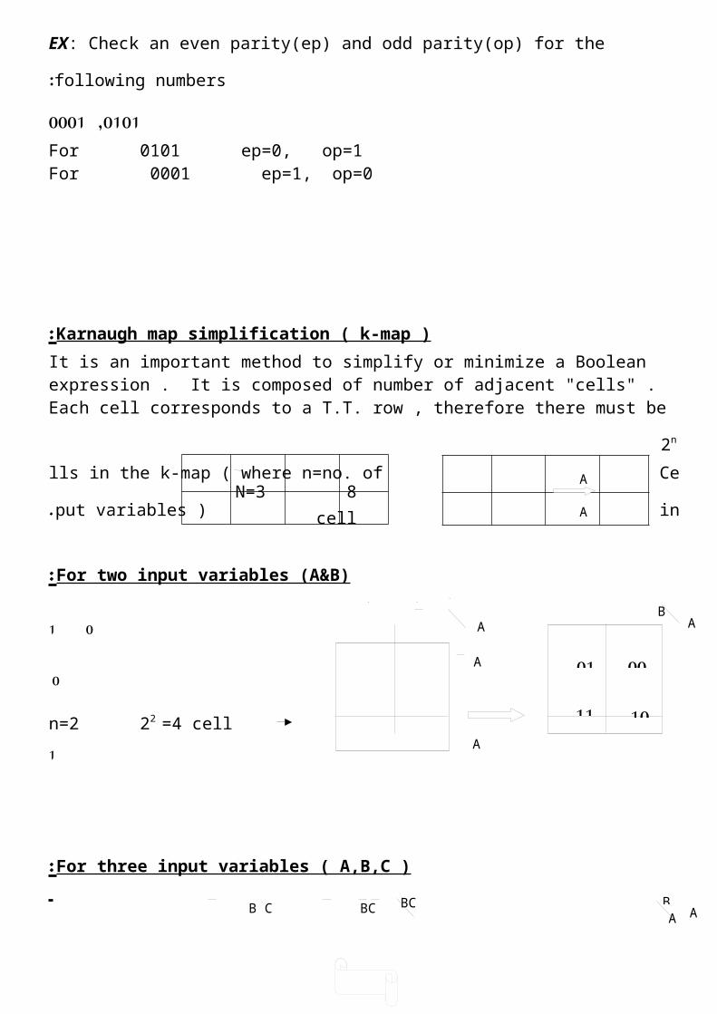
EX: Check an even parity(ep) and odd parity(op) for the following numbers: 0101 ,0001
For 0101 ep=0, op=1For 0001 ep=1, op=0
Karnaugh map simplification ( k-map ) : It is an important method to simplify or minimize a Boolean expression . It is composed of
number of adjacent "cells" . Each cell corresponds to a T.T. row , therefore there must be 2n
Cells in the k-map ( where n=no. of input variables ).
For two input variables (A&B):
0 1
0
n=2 22 =4 cell 1
For three input variables ( A,B,C ):
01
11
00
10
BA
A
B AA
A
A
B
A
B
ABC 00 01 11
10 B C BC BC BC BC
A
A
A

29
For four input variables ( A,B,C,D ):
The first step in the minimization method is to implement the T.T. to the K-map .
1’s and 0’s in the output of the T.T. is placed in the cells corresponding to the input variables of the T.T.
EX: AB Z 00 0
01 0 10 1 11 1
Ex: ABC Z 000 0 001 1 010 0 011 0 100 0 101 0
110 1 111 1
CDAB 00 01 11
10AB
CD C D CD CD CD
A B
AB
AB
AB
0 1 BA
0
1
0 0
1 1Z = B
BC A01
10 11 01 00
N=3 8 cell
N=4 16 cell
00101100

30
Adjacent cells : The adjacent cells on k- map are those that differ by only one variable ( only one variable changes from 0 to 1 or 1 to 0 )
10
10
G1 = B
G1 = AB
If more than one pair exist on k-map , we can OR the simplified products to get the final Boolean exp.
A quad is a group of four 1’s that are horizontally or vertically adjacent . two variables are eliminated in the quad group.
AB1 0
01
G1
ABC
01
00 01 11 10
G1 11
1
111
11
11
1111
11111111
1111
1111

31
Octet is group of eight 1’s that are horizontally or vertically adjacent , so three variables can be eliminated .
Over lapping: The same (1) can be used for more than one group
Rolling:
Summary of k-map method: 1-Implement the T.T. to k-map
2-Encircle the octet , quads and pairs . Remember to roll and overlap to get the largest possible group .
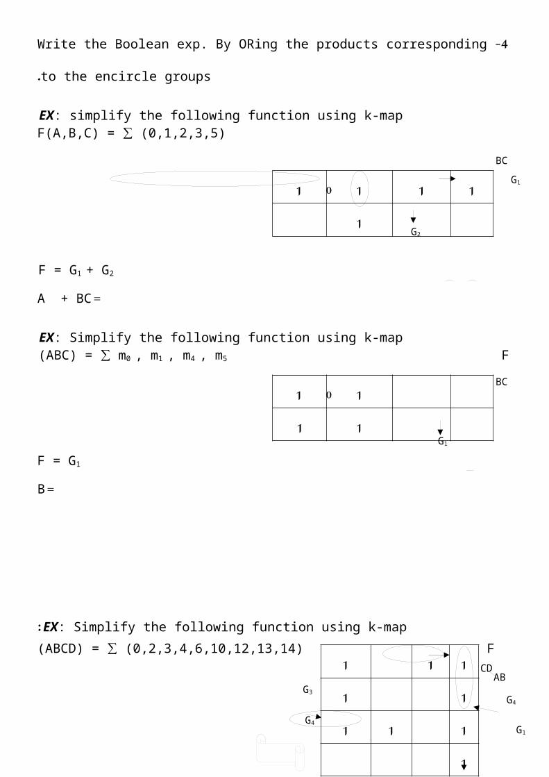
3 -If any isolated 1’s , encircle each. 4-Write the Boolean exp. By ORing the products corresponding to the encircle groups.
EX: simplify the following function using k-map
11111111
11111111
1
11111111
111111
1111
11
11
11

32
F(A,B,C) = ∑ (0,1,2,3,5)
F = G1 + G2
= A + BC
EX: Simplify the following function using k-map F (ABC) = ∑ m0 , m1 , m4 , m5
F = G1
= B
EX: Simplify the following function using k-map: F (ABCD) = ∑ (0,2,3,4,6,10,12,13,14)
F = G1 + G2 + G3 + G4
EX: Find the simplified output in PS method using k-map for the following function: F = (ABC) = π (0,1,4,6)
BC00 01 11 G1
G2
BC00 01 11
G1
00 01 11 10 CDAB
G3
G4
G2
G1
G4
ABC00 01 11
0001
11
10
1111
1
01
11
11
01
111
111111

33
F = G1.G2
( = A+B( )A+C)
EX: Simplify the following using k-map: F (ABCD) = π)0,1,2,3,5,7,8,9,10,11(
F = G1 . G2
= B(A+D)
Don ’ t care condition : Some logic ccts. can be designed so that there are certain input conditions for which there
are no specified output levels , because these input conditions will never occur. It is necessary to specify the output for these conditions by either (0) or (1) in order to
produce the simplest output exp.
EX: Simplify the following using k-map. F(ABCD) = ∑(0,3,6,15)
dcc = 1,2,10,14
F = G1 + G2 + G3
=A B + CD + ABC EX: Simplify the following function using k-map: F(ABCD) = π(5,6,7,13) dcc = (4,15)
G2
00 01 11 10 CDAB
00011110
G1
G2
00 01 11 10 CDAB
00011110
G1
00 01 11 10
00011110
ABCD
00
00 G2
000000
0000G1
d1d1
1
d1d
G3
G2
000dd0 G2

34
F = G1 . G2
( = A+B( )B+D)
H.W . : Simplify the following using PS and SP method by k-map: F(ABCD) = π(2,3,6,7,13) dcc = (0,4,8,9,10,12,14)
5- variables k-map : n =5 32 cell
A = 0 A = 1والعاموديه: األفقية عمده أال أن أي متوازية بصورة مجموعه فوق مجموعه توضع مالحظة
الثانية . المجموعة في مثيالتها مع تتجاور
EX: Simplify the following logic function using k-map : F(ABCDE) = ∑ (0,1,4,5,10,16,17,20,21,26,30,31)
A = 0 A = 1
F = G1 + G2 + G3
= B D + BCDE + ABCD
EX: Simplify the following , using k-map: F(ABCDE) = ∑ (0,1,2,3,6,15,24,25)
dcc = (7,14,17,18,21,22,25,26,29,30)
00 01 11 10 DEBC00 01 11 10 DE
BC
00 01 11 10 00011110
DEBC
G2
G1
00 01 11 10 00011110
DEBC
G2
G3
00 01 11 10 DEBC
00011110
G2
00 01 11 10 00011110
DEBC
G1
1111
11
1
G1
1111
1
dddddd
dd11
G1
11111dd1
G1

35
A = 0 A = 1
F = G1 + G2 + G3
= CD + A B C + ABC
H.W .: Simplify the following using k-map:
Code converter:
EX: design a logic cct. That convert BCD 8421 to EX-3 code: Sol:
8421 EX-3ABCD WXYZ
0000 00110001 01000010 01010011 01100100 01110101 10000110 10010111 1010
1000 10111001 1100
G3
00 01 11 10 00011110
CDAB
00 01 11 10 00011110
CDAB
Dcc = 10,11,12,13,14,15
111
1
XXXXXX1
X=
111
XXXXXX11
W=

36
EX: Design a code converter cct. That convert BCD 6311 to BCD 5421 by using k-map:
ABCD WXYZ0000 00000001 00010011 00100100 00110101 01000111 10001000 10011001 10101011 10111100 1100
00 01 11 10 00011110
CDAB 00 01 11 10
00011110
CDAB
Dcc = 2,6,10,13,14,15
00 01 11 10 00011110
ABCD
00 01 11 10 000111
CDAB
00 01 11 10 00011110
CDAB
00 01 11 10 ABCD
0001
11
11
XXXXXX1
Z=
11
11
XXXXXX1
Y=
XX1
XXX1X
X=
X
X1
XXXXX111
W= X1X1
XXXX11
Z=
X1X1
XXXX11
Y=

37
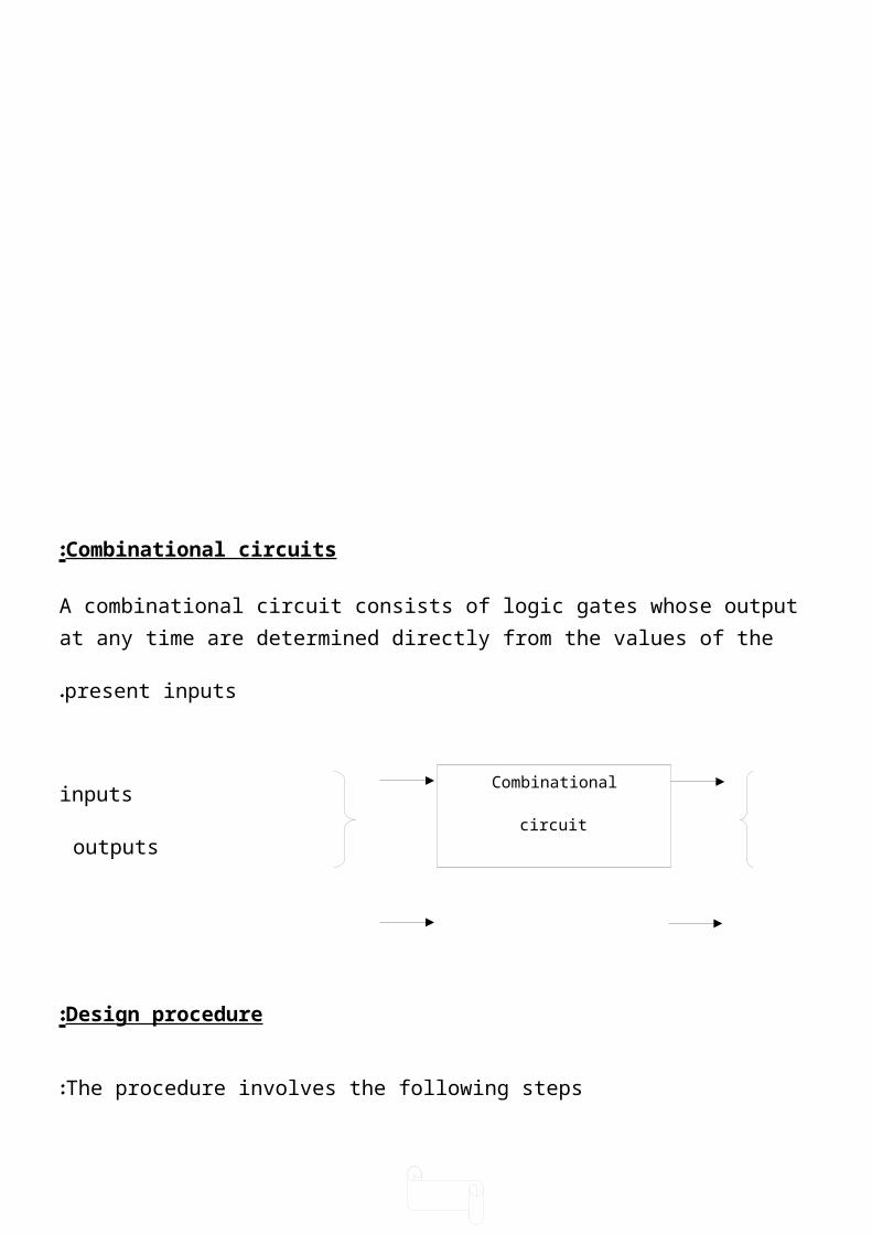
Combinational circuits:
A combinational circuit consists of logic gates whose output at any time are determined directly from the values of the present inputs.
inputs outputs
Design procedure:
The procedure involves the following steps:
1-Determine the required number of inputs and outputs.
2-Drive the truth table.
3-Obtain the simplified Boolean function for each output.
000111
0001
Combinational
circuit
38
4-Draw the logic diagram.
Half adder (H.A.):
To design a circuit that adds two numbers each of one bit for example:
Two inputs 1 0 1 0
1+ 0+ 0+ 1+
Two output 1 0 0 1 1
A B C S
0 0 0 0
0 1 0 1 S= A B + A B
1 0 0 1 C= A B
1 1 1 0
A
B

39
Using NAND gates only:
S = A B + A B
S = A B + A B = A B . A B = X . Y
C= C = A B = A B
Full adder (F. A):
من مكون واحد كل عددين جمع حالة ال bit-2في تجمع دائرة لتصميم المرحلة bitsأي في: بعدها ما و الثانية
Ci 1
A 0 1
B 1 1+
1 0 0
Carry sum
A B Ci Co S
0 0 0 0 0
A S
H.A. B C
A S
B F.A .
Ci Co
S inputs C
A B A B
A B
S
C
output

40
0 0 1 0 1
0 1 0 0 1
0 1 1 1 0
1 0 0 0 1
1 0 1 1 0
1 1 0 1 0
1 1 1 1 1
S= A B Ci + A B Ci + A B Ci + A B Ci
S= Ci( A B + A B ) + Ci( A B + A B )
S= Ci ( A + B ) + Ci ( A + B )
Let A + B = K
S= Ci K + Ci K = Ci + K
S= Ci + A + B
Co= A B Ci + A B Ci + A B Ci + A B Ci
Co= Ci ( AB + AB ) + AB ( Ci + Ci )
Co= Ci . ( A + B ) + AB
A B
S
Co

41
Using NAND gates only:
S= A B Ci + A B Ci + A B Ci + A B Ci
Co=A B Ci + A B Ci + A B Ci + A B Ci
S
42
Parallel binary adder:
من مكون منهما كل رقمين bit-2لجمع
Ex: Design a logic circuit that add (3 + 1 )D :
1 Ci
1 1 A1 A0
0 1 + B1 B0 +
1 0 0 Co S1 S0
0 1 1 1 1
Co
43
1 0 1 0
Half subtractor (H.S.):
A B Bo D
0 0 0 0
0 1 1 1
1 0 0 1
1 1 0 0
D= A B + A B = A + B
Bo= A B
B1 A1 Ci
F.A.
Co S
B0 A0
H.A.
Co S
D Bo
A B

44
Full subtractor ( F.S ):
A B Bi Bo D
0 0 0 0 0
0 0 1 1 1
0 1 0 1 1
0 1 1 1 0
1 0 0 0 1
1 0 1 0 0
1 1 0 0 0
1 1 1 1 1
D=A B Bi + A B Bi + A B Bi + A B Bi
D= Bi ( A B + A B ) + Bi ( A B + A B )
D= Bi ( A + B ) + Bi ( A + B )
D= A + B + Bi
Bo= A B Bi + A B Bi + A B Bi + A B Bi
Bo= Bi ( A B + A B ) + A B ( Bi + Bi )
Bo= Bi ( A + B ) + A B

45
Multiplexers (MUX):
Multiplexer is a combinational circuit that selects one of many input lines and direct it to a single output line. The selection of a particular input line is controlled by a set of select variables. Normally there are ( 2n ) input lines and ( n) select variables whose bit combination determines which input is selected. The 4-to-1 multiplexer is shown below:
S1 S0 Y
0 0 D0
0 1 D1

46
1 0 D2
1 1 D3
There are: 2-to-1 MUX with 1 select variable
4-to-1 MUX with 2 select variable.
8-to-1 MUX with 3 select variable .
.16-to-1 MUX with 4 select variable
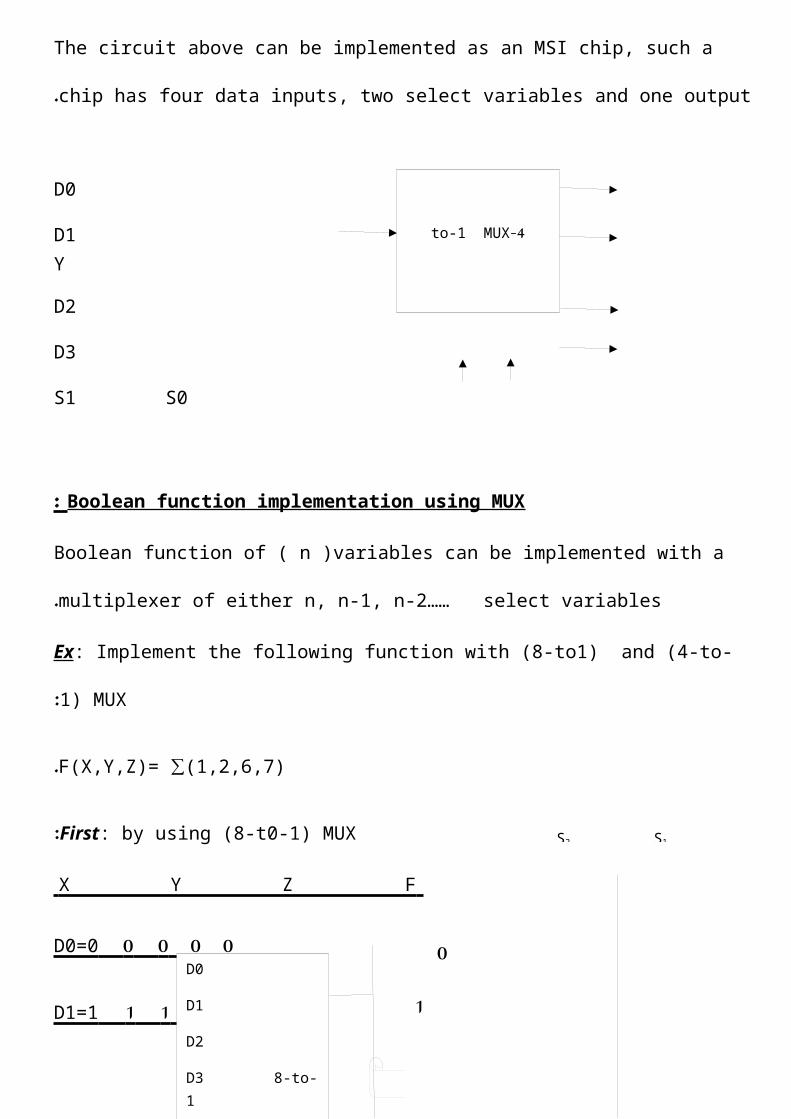
The circuit above can be implemented as an MSI chip, such a chip has four data inputs, two select variables and one output.
D0
D1 Y
D2
D3
S1 S0
4-to-1 MUX
So S1 D0 D1 D2 D3
Y

47
Boolean function implementation using MUX:
Boolean function of ( n )variables can be implemented with a multiplexer of either n, n-1, n-2…… select variables.
Ex: Implement the following function with (8-to1) and (4-to-1) MUX:
F(X,Y,Z)= ∑(1,2,6,7).
First: by using (8-t0-1) MUX:
X Y Z F
0 0 0 0 D0=0
0 0 1 1 D1=1
0 1 0 1 D2=1
0 1 1 0 D3=0
1 0 0 0 D4=0
1 0 1 0 D5=0
1 1 0 1 D6=1
1 1 1 1 D7= 1
Second: by using (4-t0-1) MUX:
X Y Z F
0 0 0 0
0 0 1 1 D0=Z
0 1 0 1
O 1 1 0 D1=Z
1 0 0 0
1 1 0 1
1 1 1 1 D3=1
D0
D1
D2
D3 8-to-1
D4 Mux F
D5
D6
D7
S2 S1
D0
D1
D2 4-to-1
D3 MUX
S1 S0
0 1
S2 S1 S0
X Y Z
Z Z 0
1
X Y
48
EX : Implement the following function using (8-to-1) and (4-to-1) MUX:
F(A,B,C,D)=∑( 1, 3, 4, 7, 11, 12, 13, 14, 15 ).
First: using (8-to-1) MUX:
A B C D F
0 0 0 0 0
O 0 0 1 1 D0= D
0 0 1 0 0
0 0 1 1 1 D1= D
0
1
2
3 8-to-1
4 MUx
5
6
D D 0 1

49
0 1 0 0 1
0 1 0 1 0 D2= D
0 1 1 0 0
0 1 1 1 1 D3= D
1 0 0 0 0
1 0 0 1 0 D4=0
1 0 1 0 0
1 0 1 1 1 D5= D
1 1 0 0 1
1 1 0 1 1 D6= 1
1 1 1 0 1
1 1 1 1 1 D7= 1
Using (4-to-1) MUX: second:
A B C D F
0 0 0 0 0
O 0 0 1 1
0 0 1 0 0
0 0 1 1 1 D0= D
0 1 0 0 1
0 1 0 1 0
0
1
2
3 8-to-1
4 MUx
5
6
D D 0 1
A B C

50
0 1 1 0 0
0 1 1 1 1 D1= C + D
1 0 0 0 0
1 0 0 1 0
1 0 1 0 0
1 0 1 1 1 D2= C . D
1 1 0 0 1
1 1 0 1 1
1 1 1 0 1
1 1 1 1 1 D3 =
1
Demultiplexer:
It is a digital circuit that performs the inverse operation of a multiplexer. It receives information from a single line and transmits it to one of 2n possible output lines. The selection of the specific output is controlled by the bit combination of (n ) select lines. A 4-to-1 DEMUX is shown below:
0
1 4-to-1 MUX
2
3 S1 S0
E
F
A B

51
For example when s1s0=10, output will be the same as the input value of E, while all the other outputs remain inactive at logic (0).
Decoder:
It is a combinational circuit that converts (n) inputs to a maximum of 2n unique outputs. A 2-to-4 decoder is shown below:
D0
D1 D2
D3
S0 S1

52
Boolean function implementation using decoder:
Any combinational circuit with ( n ) inputs and ( m ) outputs can be implemented with an n-to- 2n decoder and (m) OR gates. The Boolean function should be expressed in sum of product.
Ex : Implement a full adder function with a decoder and OR gates:
From the truth table of full adder we get:
S(X,Y,Z) =∑ 1, 2, 4, 7
C(X,Y,Z) =∑ 3, 5, 6, 7
Since there are 3- inputs and a total of 8 minterms, then we need 3-to-8 decoder.
A0 D0
2-to-4 D1
decoder D2
A0
A1
D0 =A1 A0 D1 = A1 A0 D2 = A1 A0
D3 = A1 A0

53
Encoder:
It performs the inverse operation of a decoder. It has 2n (0r less) inputs and (n) output lines.
0
1
3-to-8 2
decoder 3
4
5
Z X
Y
S C

54
It is assumed that only one input has a value of (1) at any given time, otherwise the circuit has no meaning.
For example the 8-to-3 encoder has the following T.T: .
D7 D6 D5 D4 D3 D2 D1 D0 A2 A1 A0
0 0 0 0 0 0 1 0 0 0 1
0 0 0 0 0 1 0 0 0 1 0
0 0 0 0 1 0 0 0 0 1 1
0 0 0 1 0 0 0 0 1 0 0
0 0 1 0 0 0 0 0 1 0 1
0 1 0 0 0 0 0 0 1 1 0
1 0 0 0 0 0 0 0 1 1 1
7 - segment display :
It consists of seven segments, usually LEDs or liquid crystals.
a
f g b
e c
d
we can display any decimal digit by turning on the appropriate elements (a…..g).
D0
D1 D2 A0 D3 A1 D4 A2 D5
D6 D7
8-t0-3 encoder
55
BDC - T0 -7 segment decoder:
It is a circuit with 4- bit input (BCD)and 7-outputs(segments). To display a number, the decoder must translate the input bits to the required output segment:
Digit D3 D2 D1 D0 a b c d e f g
0 0 0 0 0 1 1 1 1 1 1 0
1 0 0 0 1 0 1 1 0 0 0 0
2 0 0 1 0 1 1 0 1 1 0 1
3 0 0 1 1 1 1 1 1 0 0 1
4 0 1 0 0 0 1 1 0 0 1 1
5 0 1 0 1 1 0 1 1 0 1 1
6 0 1 1 0 0 0 1 1 1 1 1
7 0 1 1 1 1 1 1 0 0 0 0
8 1 0 0 0 1 1 1 1 1 1 1
9 1 0 0 1 1 1 1 0 0 1 1
BCD I/ps 7-seg.o/ps
Digital comparator:
It is a combinational circuit that compare two numbers A and B where each of them are 1-bit:
BCD/7 segment decoder
D0 a
D1 b
D2 c
D3 d
e
f

56
A B a :(A=B) b:(A≠B) c:(A>B) d:(A<B)
0 0 1 0 0 0
0 1 0 1 0 1
1 0 0 1 1 0
1 1 1 0 0 0
a= A + B
b= A + B
c= A B
d= A B
To compare 2-2 bit numbers:
A1 A0 =A
B1 B0=B
A=B when ( A1=B1 AND A0=B0 )
A>B when ( A1>B1) OR (A1=B1 AND A0>B0 )
1-1bit comparator
A a
B b
c
d
b a c
d
A B

57
A<B when (A1<B1) OR (A1=B1 AND A0<B0 )
Sequential circuits:
The sequential circuits consists of a combinational circuit and storage elements as shown below:
X=Y X> Y
A1 B1 A0
B0

58
Inputs outputs
next state
present state
The next state of the storage elements is a function of the inputs and the present state.
There are two types of sequential circuit:
1-Asynchronous: The stored information in the stored element depends on the input signal only.
2-Synchronous: The stored information can change only during the occurrence of a clock pulse.
The storage elements are called flip-flop (f.f. ) . There are many types of f.f: .
Set – Reset f.f. ( S-R f.f. ):
Combinational
circuit
Storage
element
S Q
CK
R Q
S CK R

59
CK S R Q Q
0 X X X
1 0 0 no change
1 0 1 0( reset )1
1 1 0 1( set )0
1 1 1 not allowed
Note: Only when ck =1, the information from S and R is allowed to reach the output Q.
D f.f: .
The only way to eliminate the not allowed state in S-R ff is to ensure that both S & R will never be 1 at the same time. This is done in D-ff:
CK D Q Q
S Q
CK
R Q
Q Q
S CK R

60
0 X X X
1 0 0 1
1 1 1 0
D
J – K f.f: .
S Q
Ck
R Q
D Q
CK Q
S Q
R Q
J Q
CK
K Q
J
K

61
CK J K Q
0 X X X
1 0 0 no change
1 0 1 0( reset)
1 1 0 1(set)
1 1 1 toggle
T – f.f: .
CK T Q T
0 x x
1 0 no change
1 1 toggle
EX : Implement the following states on S-R ff. (initial state of QQ=10 )
S R Q Q
0 1 0 1
1 0 1 0
T Q
CK Q
J Q
CK
K Q

62
1 1 not allowed
0 0 1 0
1 0 1 0
EX : Implement the following states on J-K ff (initial state of QQ=01)
J: 1 0 1 1 0 0
K: 1 0 0 1 1 0
J k Q Q
1 1 1 0 toggle
0 0 1 0 no change
1 0 1 0 set
1 1 0 1
0 1 0 1 reset
0 0 0 1 no change
Shift Register:
It is a group of flip-flops that are capable of shifting binary information in one or both directions .
Shift registers are useful in:
toggle

63
1 -Storage of serial data.
2 -Serial to parallel or parallel to serial data conversion.
3 -performing arithmetic operations
There are two types of data transfer:
1 - Serial transfer :
Where data is transferred one bit at a time by shifting the bits of one ff into the next ff and so on.
CLR
Serial
input
CK
The serial input determines what goes into left most position during the shift. The serial output is taken from the output of the right most ff. the standard graphic symbol is:
CLR
Serial input serial output
EX : Shift the following data five pulses to the right:(10111001)
D QD Q D Q D Q
SRG4
CK
Serial output

64
10011101
00111010
01110100
11101000
11010000
10100000
Parallel transfer:
Data can be transferred to or from all ffs at the same time:

65
CLR
CK
I0 I1 I2
A universal register may perform different methods of moving data into or out of register like:
1 -Parallel in – parallel out.2 -Parallel in – serial out.3 -Serial in – parallel out.
4 -Serial in – serial out. CLR
parallel load
outputs
right serial input
left serial input modes of
CK operation
Counter:
Flip-flops can be connected together to perform counting operations. The number of ffs used and the way in which they are connected determine the number of states (called modulus ).
Basically counters are of two types:
1 -Asynchronous counter ( Ripple counter ) :
D Q D QD Q
A QA
B QB
C QC
D QD
RS
LS S1 S0

66
An external clock signal is applied to the first ff and then the output of the preceding ff is connected to the clock of the next ff.
EX: Design 2- bit asynchronous binary counter:
Clk Q1 Q0 logic (1)
Initially 0 0
1 0 1
2 1 0
3 1 1
4 0 0
H.W. :Design 3- bit asynchronous counter.
BCD decade counters ( MOD 10 ):
The number of states are ten (0000 – 1001). In this type the counter should be count back to (0000) after (1001).
0000 ,0001 ,0010 ,0011 ,0100 ,0101 ,0110 ,0111 ,1000 ,1001
J1 Q1
CK
K1 Q1
J0 Q0
Ck
K0 Q0
67
Skipped Q3 Q2 Q1 Q0
1 0 1 0 0 1
CLR
EX : Design MOD 7 counter:
The counter should count from 000- 011 so there are 3 ffs. But state 111 should be skipped:
logic(1)
J1 Q1
CK
K1 CLR
J0 Q0
CK
K0 CLR
J2 Q2
CK
K2 CLR
J3 Q3
CK
K3 CLR
J1 Q1
CK
K1 CLR
J2 Q2
CK
J0 Q0
CK
Logic(1)

68
H.W. :Design MOD 12 counter (0000 – 1011)
2- Synchronous counter ( parallel counter ) :
All the ffs in the counter are clocked at the same time by a common clock pulse.
EX : Design 2-bit counter:
Clk Q1 Q0
Initially 0 0
1 0 1
2 1 0
3 1 1
4 0 0
EX : Design 3-bit synchronous counter:
CLK Q2 Q1 Q0
Initially 0 0 0
J1 Q1
CK
K1 CLR
J2 Q2
CK
J0 Q0
CK
J0 Q0
CK
K0
J1 Q1
CK
K1 Q1
Logic(1)
CLK
Logic(1)

69
1 0 0 1
2 0 1 0
3 0 1 1
4 1 0 0
5 1 0 1
EX: Design 4-bit Johnson counter:
CLK Q0 Q1 Q2 Q3
0 0 0 0 0
1 1 0 0 0
2 1 1 0 0
3 1 1 1 0
4 1 1 1 1
5 0 1 1 1
6 0 0 1 1
7 0 0 0 1
EX: Design 4- bit Ring counter:
0 1 0 0 0
1 0 1 0 0
2 0 0 1 0
J2 Q2
CK
K2
J1 Q1
CK
K1
J0 Q0
CK
K0
D0 Q0
CK
D1 Q1
CK
D2 Q2
CK
D3 Q3
CK Q3
D0 Q0
CK
D1 Q1
CK
D2 Q2
CK
D3 Q3
CK
CLK
CLK

70
3 0 0 0 1 CLK
Note: initially a (1) present into first ff and the rest are cleared.
ROM( read only memory):
A ROM contains permanently or semipermanently stored data, which can be read from the memory but either cannot be changed at all or cannot be changed without specialized equipment. ROMs retain stored data when the power is OFF.
ROM family:
A simple ROM:
EX: Draw 16x8 ROM: 1 0
ROM
EPROMUVPROMEEPROM PROM Mask
ROM
Address 0
Decoder 1
4-16 2

71
Address
Input
lines
……………………
0 1 6 7
data output lines (word)
ROMs can be used as look-up-tables (LUT) for code conversion and logic function.
EX: Show a ROM programmed for 4-bit binary to gray conversion:
Binary Gray
A B C D W X Y Z
0 0 0 0 0 0 0 0
0 0 0 1 0 0 0 1
0 0 1 0 0 0 1 1
. .
. .
1 1 1 1 1 0 0 0
Address
Input
Address 0
Decoder 1
4-16 2
Address 0
Decoder 1
4-16 2
3
4
A ROM W
B X
C 16x4 Y
D Z

72
lines
……………………
0 1 6 7
data output lines (word)
Memory expansion:
Memory chip is basically as below:
EX: 16K x 1 ROM CS (chip select)
A1
. Data line
.
A14
EX: construct (64K x 16) memory using (16K x 1) memory chip:
64K = 216 16 address line ( A1………A16)
16K= 214 14 address line (A1………A14)
We need 64K= 4 row
16K
We need 16 = 16 column
1
16 -14 = 2 ( A15 , A16 ) we use them in a 2- to-4 decoder to select rows:
Address 0
Decoder 1
4-16 2
3
4
16K x 1

73
CS1
CS2 A15 ...……………………………
A16 CS3 ..……………………………
CS4…………………………………
EX : construct (4K x 4) memory using (1K x 4) memory chip.
4K = 4 row , 4 =1 column
1K 4
4K= 212
1K= 210 12-10=2 then we use 2-to-4 decoder
A1
A10
2-to-4
decoder
16K x 116K x 116K x 1
16K x 1
16K x 1
16K x 116K x 1
16K x 1
16K x 1
2-to-4
decoder
1K x 4
1K x 4 A11 A12
D1 . . D4 D1 . .
D1 . D4

74
1K x 4
1K x 4
A11 A12
D1 . . D4 D1 . .
Related Documents