Unsteady Flow Structure and Global Variables in a Centrifugal Pump José González Pérez Carlos Santolaria Morros ASME Journal of Fluids Engineering. Septiembre 2006.

Welcome message from author
This document is posted to help you gain knowledge. Please leave a comment to let me know what you think about it! Share it to your friends and learn new things together.
Transcript

Unsteady Flow Structure and Global Variables in a Centrifugal Pump
José González Pérez Carlos Santolaria Morros
ASME Journal of Fluids Engineering. Septiembre 2006.
I
odoftbt
ahhlv�lua
aflbpi�o�p
twvs
Jr
J
José Gonzáleze-mail: [email protected]
Carlos Santolaria
Área de Mecánica de Fluidos,Universidad de Oviedo,
Campus de Viesques,33271 Gijón (Asturias), Spain
Unsteady Flow Structureand Global Variables in aCentrifugal PumpA relationship between the global variables and the dynamic flow structure numericallyobtained for a low specific speed centrifugal pump is presented in this paper. A previouslydeveloped unsteady flow model is used to correlate the dynamic field with the flowcharacteristics inside the impeller and volute of a single-stage commercial pump. Actu-ally, the viscous incompressible Navier-Stokes equations are solved within a 3D unsteadyflow model. A sliding mesh technique is applied to take into account the impeller-voluteinteraction. After the numerical model has been successfully compared with the experi-mental data for the unsteady pressure fluctuations pattern in the volute shroud, a newstep is proposed in order to correlate the observed effects with the flow structure insidethe pump. In particular, the torque as a function of the relative position of the impellerblades is related to the blades loading, and the secondary flow in the volute is related tothe different pressure patterns numerically obtained. Local flow analysis and qualitativestudy of the helicity in different volute sections is performed. The main goal of the studypresented is the successful correlation of local and global parameters for the flow in acentrifugal pump. The pressure forces seem to be the main driven mechanism to establishthe flow features both in the impeller and volute, for a wide range of operatingconditions. �DOI: 10.1115/1.2234782�
ntroductionThe complexity of any study of the flow in a turbomachine is
bvious and has led to much of the research work over recentecades �1�. Referring to pumps, many studies have been carriedut, but even nowadays some flow events are still under study andar from being fully understood �2–4�. Moreover, the presentrends towards smaller �more compact� units and more loadedlades complicate the issue and produce new and unexpected pat-erns.
Nowadays, pump technology constitutes a major research fieldmong cutting-edge technological companies. Some authors �3,5�ave classified the various efforts into different categories, namelyydraulics �losses and static performance�, cavitation �modern so-utions and modifications to prevent the appearance of this effect�,ibrations �dynamic effects of the flow�, and machine arrangementshaft and bearing configurations�. Nevertheless, only during theast decades, have the modern designs tried to take into accountnsteady or dynamic effects, which were impossible to determinend ignored by the classical design procedures �4,6�.
When a dynamic study is proposed, difficulties arise in tworeas: geometrical variables, which are quite complex, and theow varying from its regular or symmetrical state. Sometimesoth difficulties interact, producing an extremely distorted flowattern �3�. The pressure fluctuations interact with the volute cas-ng or even with the circuit and give rise to dynamic effectsmainly unsteady forces� over the mechanical parts, which are onef the most important sources of vibration and hydraulic noisesee Ref. �7� for a general review and see Refs. �8,9� for morearticular studies�.
For centrifugal pumps, several experimental data, starting withhe historical articles �10,11� and including more recent ones, inhich extremely advanced measuring techniques �12–14� or evenisualization techniques are employed �9,15,16�, have been pre-ented in previous studies. All this knowledge is now available
Contributed by the Fluids Engineering Division of ASME for publication in theOURNAL OF FLUIDS ENGINEERING. Manuscript received May 11, 2004; final manuscript
eceived February 24, 2006. Assoc. Editor: Jinkook Lee.ournal of Fluids Engineering Copyright © 20
and the databases constructed from these works constitute a veryrich seed for the new advances; as for example, �14� have mea-sured the unsteady pressure field inside the impeller of a centrifu-gal pump using piezoresistive pressure transducers and a telem-etry system. They measured pressure pulses amplitude and foundthat they were particularly high at the trailing edge of the blades,on their pressure sides, and reached even 35% of the pump head atoff-design conditions.
On the other hand, the application of numerical procedures tothis industry has provided a very valuable tool �17,4�. For ex-ample, today it is possible to predict the performance curve andstatic pressure distributions with amazing accuracy, in the veryearly design stages. Such information accelerates the whole de-sign cycle and produces an enormous time and money saving inthe final product �5�. The evolution of numerical flow studies hasalso undergone a tremendous development in recent years �seeRef. �18� for general applications and see Refs. �19,20� for a moreparticular research on pumps�. Many flow aspects have been nu-merically analyzed and, for example, �20� reports an adequate andaccurate performance description for an axial or mixed-flow pumpusing coarse CFD models.
One specific turbomachinery feature that constitutes the drivingmechanism for the dynamic effects on a centrifugal pump is theso-called rotor stator interaction. Although the impeller blades areequally spaced, nonaxis symmetry appears due to the geometricalrestriction that the volute tongue causes on the flow leaving theimpeller �21–23�. Different possibilities for the numerical study ofthe rotor-stator interaction in a centrifugal pump have been con-sidered and widely reported �24–26�. Ranging from a separatecalculation in impeller and volute to the full unsteady models,some other possibilities like the mixing plane or the frozen rotorcomputations have shown their advantages and drawbacks. Themain conclusion from those models is the need for a fully un-steady calculation with relative motion of the impeller if the dy-namic effects are to be taken into account. Reference �24� showedresults of a numerical simulation using the sliding mesh tech-nique. Although they found some problems in the comparison of
their results with the experiments, they pointed out the profits ofSEPTEMBER 2006, Vol. 128 / 93706 by ASME

tnc
cptaestthpt
spstaadotlwttt
aIcott
P
dasbtll3
1fpa
9
he method and foresaw the implementation of this method in theumerical solutions to handle the particularities of the turboma-hinery flows.
In this work a numerical fully unsteady model, already dis-ussed and validated �27,28� is used as analysis tool. From thoserevious studies, it has been noted how the two main contribu-ions to the fluctuations obtained at the blade passing frequencyre the flow structure exiting from the impeller and the tongueffect itself. The effects of the first one represent the jet-waketructure at all the angular positions. The second one correspondso the effect felt in any point due to any blade facing the voluteongue. From the different flow rates investigated, both effectsave been compared and highest influence is found at the bladeassing frequency. Those effects have been also numerically cap-ured.
In the frame of the numerical model described, a detailed flowtudy inside the impeller and volute of a single stage centrifugalump is shown here. In particular, a relationship between the un-teady pressure patterns in the volute of a centrifugal pump andhe different instantaneous flow fields obtained is researched usingCFD technique, which includes the sliding mesh technique withfully unsteady calculation. Some flow patterns are often very
ifficult or impossible to measure directly and cover a wide rangef very important unsteady aspects, such as: torque pulsations inhe impeller shaft for different flow rates in function of the impel-er relative position; incidence at the leading edge of the bladesith different flow conditions; and secondary flows generated in
he volute due to the radial gap change between the impeller andhe tongue. An example of these secondary flow patterns is alsohoroughly investigated.
In order to ensure the correctness of the numerical results, it islways desirable to have as many experimental data as possible.n this work, an intensive series of laboratory measurements isarried out at positions where the accessibility of the pump’s ge-metry allowed doing so. Particularly, the pressure pulsations onhe shroud side are measured for different circumferential loca-ions and several flow rates.
ump Facility and Measurements ChainA hydraulic facility designed according to International Stan-
ards �29� is used for the experiments. The water is pumped fromnd returned to a 100 m3 reservoir. The radial flow pump has aingle axial suction duct and a vaneless volute casing. It is aackward curved blade commercial pump, with the main charac-eristics shown in Table 1. The flow rate uncertainties are calcu-ated and found to be always less than 2.5%, with a confidenceevel of 95%. The head and efficiency uncertainties are kept below% and 4%, respectively, within the same confidence level.
On the volute shroud, 36 pressure taps are located, one every0 deg, in a circumference just behind the impeller exit. Miniatureast-response piezoelectric pressure transducers Kistler-601 arelaced in these taps. The transducers are connected to a charge
Table 1 Main characteristics of the centrifugal pump
mplifier, which produces a pressure measurement with an esti-
38 / Vol. 128, SEPTEMBER 2006
mated combined uncertainty of less than ±1.5%. An optic devicepointing at the pump shaft gives the triggering signal to start allthe measurements at the same impeller position. The resultingpressure signals, as well as the signal from the tachometer aredigitized and stored in a personal computer equipped with a mul-tichannel analog-to-digital conversion card. After the signals arerecorded, spectral analysis �using a fast Fourier transform withHanning window� is performed. The positioning of the pressuretaps on the shroud side of the pump is shown in Fig. 1. A moredetailed description of such arrangement together with the uncer-tainties calculation was described in Ref. �30�.
A FAST Technology torquemeter is also available for the ex-periments. The torque range is 0–175 N m and the combined un-certainty of this torquemeter and the amplification system �cables,display, and amplificator� is kept for the particular values of theexperiments under ±0.2%.
Numerical Model
Geometry, Grid, and Flow Solver. The discretization of thegeometry is done keeping the balance between calculation time�details included in section numerical solution control� and theaccuracy order of the simulation of the flow structure. Special careis taken in the near tongue region by carrying out a detailed studyof flow vectors and stagnation point placement. Structured hexa-hedral cells are generated to define the inlet and outlet zones�more than 34,500 cells and around 45,000 cells, respectively�while unstructured tetrahedral cells are used to define the impellerand volute �almost 163,000 cells and 90,000 cells, respectively�. Afinal grid with around 335,000 cells defines the whole geometry.In the volute, a mesh refinement zone is defined for a region nearthe tongue. Once the geometry is defined, the model is ready to besimulated. The grid generated for both the volute and the impelleris shown in Fig. 2, stressing these particular features.
The numerical model, which is implemented on a commercialcode �FLUENT�, solves the fully 3D incompressible Navier-Stokesequations, by including the centrifugal force source in the impellerand the unsteady terms. Turbulence is simulated with the standardk-� model. For such calculations, wall functions, based on thelogarithmic law, have been used. The time dependent term schemeis second order, implicit. The pressure-velocity coupling are cal-culated through the SIMPLEC algorithm. Second order, upwind dis-cretizations have been used for convection terms and central dif-ference schemes for diffusion terms. Although grid size is notadequate for a full investigation of local boundary layer variables,global values are well captured and the details of the flow near thetongue and blade wakes do follow the usual trends found in thebibliography �13,23�.
Boundary Conditions. The modeled boundary conditions arethose considered most physically meaningful for turbomachineryflow simulations and those which give a flow solution neitherlimited nor restricted by them �for any flow rate�: Particularly,total pressure at the inlet and a pressure drop proportional to thekinetic energy at the outlet. The flow rate is changed by modifyingthe constant for that pressure drop at the outlet, which simulates
Fig. 1 General view of the pump. The transducers were placedon the shroud side.
the closure of a valve. These boundary conditions avoid the defi-
Transactions of the ASME

nosbc
fisapp
At�agttpqb
atfl1tavse
SFtovmwtao
Ff
J
ition of a uniform and constant velocity profile at the inlet orutlet, which, in general, would not be so realistic. Also, the no-lip condition with a logarithmic law for the boundary layers haseen imposed over the impeller blades and sidewalls, the voluteasing and the inlet and outlet pipe walls.
At the inlet and exit pipes, there is an unavoidable effect on thenal flow solution as a result of the boundary conditions. A rea-onable length must be added to the real machine geometry tovoid this effect as much as possible and to better simulate theumping circuit influence. As can be observed in Fig. 2, an im-ortant effort has been devoted to overcome this problem.
Unsteady Solution Characteristics. A cluster with twelvethlon-K7 �500 MHz� nodes is used for the calculations. The
ime step used in the unsteady calculation has been set to 2.9410−4 s in order to have enough time resolution for the dynamic
nalysis; Courant number is kept below 2, which assures veryood time accuracy and numerical stability. The impeller grid ro-ation is related to this time step and also to the rotational speed ofhe pump ��=169.65 rad/s�. Therefore, a complete revolution iserformed each 126 steps. This is done in order to keep the fre-uency resolution well above the blade passing frequency and itsasic harmonics.
The number of iterations has been adjusted to reduce the residu-ls to below an acceptable value at each time step. In particular,he ratio between the sum of the residuals and the sum of theuxes for a given variable in all the cells is reduced to the value of0−5 �five orders of magnitude�. Initializing the unsteady calcula-ion with the steady solution, more than five impeller revolutionsre necessary to achieve a fully periodic unsteady solution con-ergence. The whole procedure �rotor frozen solution and un-teady calculation� takes one week with the available CPU, forach of the operating points analyzed.
The grid size dependence is studied through intensive tests.everal grid spacings are considered in successive refinements.irst of all, a 2D model had been developed, where preliminary
ests pointed out the limitations of this strong simplification andther relevant features. In particular, the grid spacing near theolute tongue had been observed as a main parameter. When a 3Dodel was first developed �28�, this feature still influenced thehole flow solution. For the 3D model, many grid dependence
ests had been carried out and more conclusions obtained. Mainly,clear inlet and outlet boundary conditions were found to be the
ig. 2 Sketch of the pump unstructured mesh and its maineatures
rigin of difficulties, not only the kind of boundary conditions, but
ournal of Fluids Engineering
also the relative position of these conditions to the impeller. Start-ing from that first 3D model, an increase of the inlet and exit pipelengths is achieved in order to preserve the solution from theimposed boundary conditions. With this 3D final model, some fullmachine tests are carried out. Different meshes are considered upto 700,000 cells. The overall performance of the pump is kept thesame for the definitive grids, even with less than a half of the cellsfinally used for the computations �the variations observed in flowrate, head and efficiency remained below very reasonable values,always less than 1.2%�. Although the static values can vary withinthat range, more detailed flow patterns, especially near the walls,are observed with increasing cell numbers. The numerical accu-racy for the pressure fluctuations is estimated to be 0.001 timesthe dynamic pressure �non-dimensional values, that is the pressureamplitude divided by 1/2�U2
2�.The time step used to obtain the present results is also checked
by repeating the numerical calculations with a half of its value�1.47�10−4 s, that is 252 steps for each complete revolution ofthe impeller� and, therefore, doubling the frequency accuracy. Thedifferences in the pressure fluctuations found are two orders ofmagnitude below the estimated numerical accuracy. During thenumerical study, the guidelines proposed by the classical theorieson numerical accuracy where followed; a summary is given by�31�.
Experimental and Numerical Dynamic ResultsBefore the unsteady calculations were made, a comparison for
both the numerical and experimental performance curves for thetested pump was carried out. The results in static variables �head,flow rate, momentum, efficiency�, taking into account that thenumerical model does not consider the disk friction losses andmechanical losses at the bearings, match very well with the ex-perimental measurements �28�. Moreover, the static pressure dis-tributions around the impeller are also well predicted with respectto the measured values and are intensively compared �32�.
Referring to the dynamic pressure fields inside the volute fordifferent flow rates, one possible comparison is with the pressurevalues at the shroud of the pump. An example of that comparisonis shown in Figs. 3 and 4, where nondimensional values of pres-sure fluctuations at the blade passing frequency, pA divided by1/2�U2
2, are compared for the numerical and experimental results.Although some differences were found and discussed, very goodagreement for all flow rates has been also obtained �see Ref. �32�for a full flow rate range comparison�.
Basically, there will be five numerical variables considered.First, a summary of the pressure fluctuations at the blade passing
Fig. 3 Comparison of the pressure fluctuations at the fBP forQ=QN. Tongue at �=0 deg.
frequency observed as function of the axial position are presented
SEPTEMBER 2006, Vol. 128 / 939

�pl
G
ccaa
todTersms
flpmroaam
FQ
Fuc
9
the core of this study was already published, �28�� and then, theressure distributions, the torque instantaneous evolution, the ve-ocity fields and the helicity in radial planes will be considered.
lobal Flow VariablesThe global frame of the study is settled by considering the
omparison between the average measured torque and the numeri-al model prediction. The instantaneous torque evolution is onlyvailable in with the numerical results. The pressure fluctuationst different axial planes are then analyzed.
Instantaneous Total Torque in the Impeller. First of all, theorque in the pump shaft is analyzed to establish the global effectn the pump shaft induced by the flow. With this goal in mind,ifferent instantaneous torque values are numerically obtained.he equivalent experimental values are not available as only av-rage torque is captured with the measuring devices used in thisesearch. The relationship between torque and pressure patternshould be straightforward if one considers that the former is theain effect of the local distinct values of the latter between pres-
ure and suction side of the blades.Figure 5 shows the total torque in function of time for the three
ow rates considered. The average torque during a blade passingeriod for each flow rate is considered in order to obtain nondi-ensional values. Maximum variation is found for the lower flow
ate, while for the nominal flow rate an almost constant torque isbtained, independently of the blade positions. On the other hand,n opposite evolution of the total torque is found for the highernd lower flow rates. For the shown period, the former reaches itsinimum whereas the latter has its maximum �at an instant be-
ig. 4 Comparison of the pressure fluctuations at the fBP for=1.5 QN. Tongue at �=0 deg
ig. 5 Instantaneous torque in the impeller „numerical val-es…. A representation of the three time instants „A, B, and C…
onsidered along the present study is shown.
40 / Vol. 128, SEPTEMBER 2006
tween 0.412 and 0.413 s�.In conclusion, a good correlation is found for the two sets of
variables considered �pressure distribution and torque are clearlyrelated�. Global variable trends �total torque� follow the expectedrelative evolution from the observed pressure field and, therefore,agree with the local flow numerically obtained. As far as thetorque evolution has been compared with experimental data andgood agreement was found, the afore-mentioned conclusionstresses the fact that the pressure forces are considerably morerelevant than any other effect �viscous or momentum changes,among others, which are included in the global variable� for thiskind of centrifugal pump.
The torque evolution cannot be obtained experimentally on anunsteady basis, but the average value for the different flow ratesstudied is compared. The result of this comparison gives a nondi-mensional difference of 0.05 for the nominal flow rate, 0.1 for thehigher flow rate and 0.07 for the lower flow rate, with highervalues measured in the experimental setup. These values can beeasily plotted in Fig. 5, but the experimental uncertainty �depend-ing on the flow rate� must also be considered. In any case andbecause of the simplifications introduced by the model, there is aslight underestimation of the torque needed for all the whole flowrate range.
Pressure Fluctuations at Different Axial Planes. As a secondand different approach to be considered, the pressure fluctuationsat the blade passing frequency are analyzed. Such a study is car-ried out in order to obtain information on the secondary flowpatterns and possible influence on the axial evolution of thesepressure fluctuations. As stated in the previous section, the pres-sure fluctuating patterns have been already studied and comparedwith experimental data in previous works �32�. The stress here isplaced on the axial evolution of this variable.
Three different axial planes are considered in the present analy-sis of the pressure fluctuations �see the scheme in Fig. 6�, one nearthe hub, another close to the shroud and a central one �in the threeplanes, the circumferential points considered are placed on a sec-tion just beyond the impeller exit, as shown in Fig. 6�. The planewith the experimental data available is distinguished by a differentrepresentation. For all flow rates, a parallel behavior is found�Figs. 7–9�. In particular, it is clear that there are similar values forthe fluctuations in both side planes �shroud and hub� and a highervalue for the central plane. All the differences in the fluctuationsobtained for the three axial planes studied are the result of theflow pattern in the volute entrance, where the strong diffusion ofthe flow �due to increase of the normal section� causes a verycomplex secondary flow, similar to the results reported by �33�.The general trend on the pressure differences indicates lower dif-ferences between different axial planes for increasing flow rate. In
Fig. 6 Different axial planes considered in the numerical study
particular, the value of the fluctuations in the central plane double
Transactions of the ASME

t�8l�a9tt
cvittcl
F
aroiffa
Fa=
Fa=
J
he equivalent values in the sidewalls, at least for 120 deg��360 deg, as can be observed in Fig. 7. For high flow rates �Figs.and 9�, these differences are lower �maximum about 20% of the
ocal value in all the angular positions�. For the nominal flow rateFig. 8� the differences remains more constant for the differentngular positions than for the off-design conditions �Figs. 7 and�. At this point, it must be kept in mind that these pressure fluc-uations are filtered at the blade passing frequency, and thereforehe effect of other peak values are not considered.
Then, when operating far from the nominal flow rate, the pumpreates a strong difference in the pressure fluctuations around theolute for the three different axial planes considered. This resultsn an increase of pressure fluctuations in the centre-plane. In par-icular, the greatest differences between these three planes arise athe lower flow rate considered �0.5 QN�. This behavior will beonsidered when observing a local flow variable, namely the he-icity.
low Study Using the Numerical ModelA numerical simulation as a means of studying the flow insidepump has wider possibilities than experiments. For example,
esults corresponding to the flow structure can be captured with-ut specific and expensive arrangements both in the impeller ornside the volute discharge. The latter is very interesting not onlyor the prediction of the losses during the pressure recovery �dif-usion� process for which the volute is designed but also to char-cterize the secondary flow pattern inside a pump �34�.
ig. 7 Nondimensional pressure fluctuation at the fBP for threexial positions at the volute. The tongue is at �=0 deg and Q0.5 QN.
ig. 8 Nondimensional pressure fluctuation at the fBP for threexial positions at the volute. The tongue is at �=0 deg and Q
QN.ournal of Fluids Engineering
Two specific flow features are analysed in the present study:first, the relationship between pressure loading on the blades andtorque and, second, a possible correlation between pressure fluc-tuations and vorticity changes in the volute. In both cases, flowrate dependence is considered for design and off-design condi-tions. The instantaneous torque and the pressure fluctuations havebeen already shown and therefore, in what follows, the other twovariables will be considered.
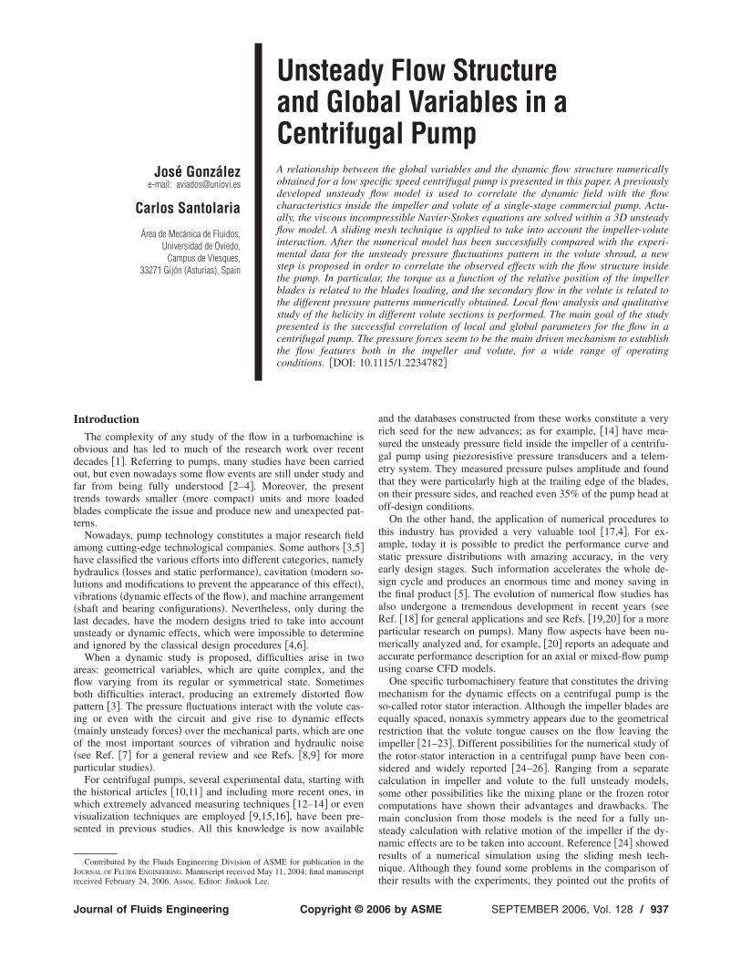
Flow Field as Function of Relative Blade Position. As a firstapproach, averaged fields are studied in order to evaluate the over-all trends. Although both pressure and velocity are studied, thefocus is placed on the velocity fields. Figure 10 shows the abso-lute velocity vectors in the near tongue region for three differentflow rates and for the same blade positions. A midspan pseudos-tream surface �between hub and shroud� is considered for thisfigure. As expected from other published data �13�, stagnationpoint moves around the tongue depending on the flow rate, ap-pearing at the volute tongue symmetry position only at the nomi-nal flow rate �Fig. 10, upper right figure�. For low flow rates �Fig.10, upper left figure for 0.5 QN�, a low velocity region is obtainedon the discharge pipe zone and the stagnation point occurs placedon the pipe side of the volute tongue. For high flow rates �Fig. 10,lower figure, for 1.5 QN�, a strong recirculation bubble is found inthe impeller side and the stagnation point occurs towards thisbubble, whereas another bubble appears in the discharge pipe,decreasing the possible pressure recovery effect of the volute.Considering the volute tongue tip as a semi-cylinder with radiusR, the position of the stagnation point is at the symmetry plane forthe nominal flow rate, at 0.4R and in the upstream �exit direction�for the lower flow rate and at 2.5R in the upstream �impellerdirection� for the higher one.
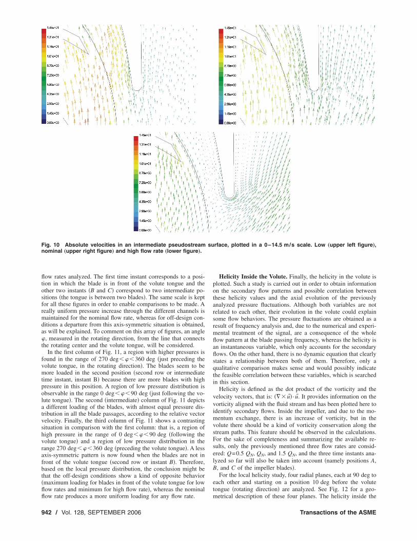
Once the averaged fields have been studied and good agreementwith the expected trends had been found, instantaneous distribu-tions of the flow variables inside the impeller are considered inorder to correlate the different states with the torque needed tocause the impeller movement in each instant. Again, a pseudos-tream surface placed half-way between hub and shroud is chosenfor this flow study. Again, three significant flow rates are consid-ered, namely Q=0.5 QN, QN, and 1.5 QN. Figure 11 shows thepressure in the before-mentioned midspan pseudostream surfacefor three flow rates and for three different relative impeller-tonguepositions �three time instants for a blade passing period, named A,B, and C in Fig. 5�. Following a representation in which the threeflow rates are presented in three columns and each time instant ispresented in the same row, a figure array is built. Therefore, inFig. 11 each figure row corresponds to one of the three time in-
Fig. 9 Nondimensional pressure fluctuation at the fBP for threeaxial positions at the volute. The tongue is at �=0 deg and Q=1.5 QN.
stants considered and each column corresponds to one of the three
SEPTEMBER 2006, Vol. 128 / 941
fltosfrmda�t
fvmtpolatvshvrafbt�flfl
Fn
9
ow rates analyzed. The first time instant corresponds to a posi-ion in which the blade is in front of the volute tongue and thether two instants �B and C� correspond to two intermediate po-itions �the tongue is between two blades�. The same scale is keptor all these figures in order to enable comparisons to be made. Aeally uniform pressure increase through the different channels isaintained for the nominal flow rate, whereas for off-design con-
itions a departure from this axis-symmetric situation is obtained,s will be explained. To comment on this array of figures, an angle, measured in the rotating direction, from the line that connects
he rotating center and the volute tongue, will be considered.In the first column of Fig. 11, a region with higher pressures is
ound in the range of 270 deg���360 deg �just preceding theolute tongue, in the rotating direction�. The blades seem to beore loaded in the second position �second row or intermediate
ime instant, instant B� because there are more blades with highressure in this position. A region of low pressure distribution isbservable in the range 0 deg���90 deg �just following the vo-ute tongue�. The second �intermediate� column of Fig. 11 depicts
different loading of the blades, with almost equal pressure dis-ribution in all the blade passages, according to the relative vectorelocity. Finally, the third column of Fig. 11 shows a contrastingituation in comparison with the first column: that is, a region ofigh pressure in the range of 0 deg���90 deg �following theolute tongue� and a region of low pressure distribution in theange 270 deg���360 deg �preceding the volute tongue�. A lessxis-symmetric pattern is now found when the blades are not inront of the volute tongue �second row or instant B�. Therefore,ased on the local pressure distribution, the conclusion might behat the off-design conditions show a kind of opposite behaviormaximum loading for blades in front of the volute tongue for lowow rates and minimum for high flow rate�, whereas the nominal
ig. 10 Absolute velocities in an intermediate pseudostreamominal „upper right figure… and high flow rate „lower figure….
ow rate produces a more uniform loading for any flow rate.
42 / Vol. 128, SEPTEMBER 2006
Helicity Inside the Volute. Finally, the helicity in the volute isplotted. Such a study is carried out in order to obtain informationon the secondary flow patterns and possible correlation betweenthese helicity values and the axial evolution of the previouslyanalyzed pressure fluctuations. Although both variables are notrelated to each other, their evolution in the volute could explainsome flow behaviors. The pressure fluctuations are obtained as aresult of frequency analysis and, due to the numerical and experi-mental treatment of the signal, are a consequence of the wholeflow pattern at the blade passing frequency, whereas the helicity isan instantaneous variable, which only accounts for the secondaryflows. On the other hand, there is no dynamic equation that clearlystates a relationship between both of them. Therefore, only aqualitative comparison makes sense and would possibly indicatethe feasible correlation between these variables, which is searchedin this section.
Helicity is defined as the dot product of the vorticity and thevelocity vectors, that is: ���u�� ·u� . It provides information on thevorticity aligned with the fluid stream and has been plotted here toidentify secondary flows. Inside the impeller, and due to the mo-mentum exchange, there is an increase of vorticity, but in thevolute there should be a kind of vorticity conservation along thestream paths. This feature should be observed in the calculations.For the sake of completeness and summarizing the available re-sults, only the previously mentioned three flow rates are consid-ered: Q=0.5 QN, QN, and 1.5 QN, and the three time instants ana-lyzed so far will also be taken into account �namely positions A,B, and C of the impeller blades�.
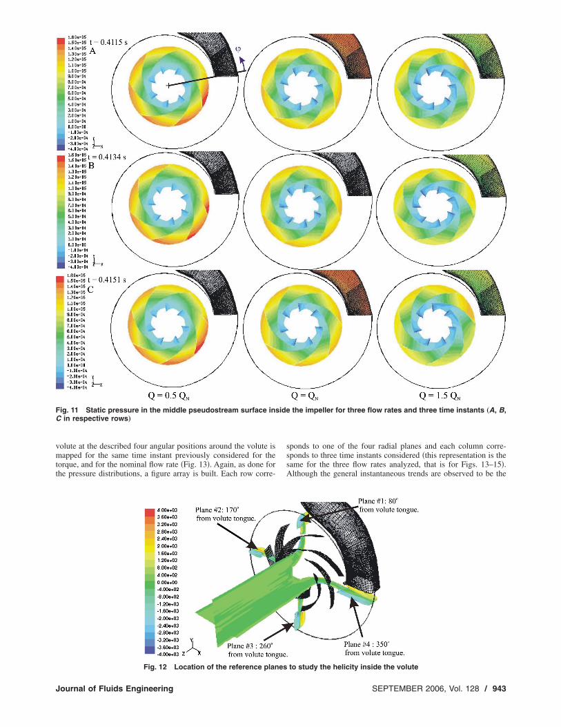
For the local helicity study, four radial planes, each at 90 deg toeach other and starting on a position 10 deg before the volutetongue �rotating direction� are analyzed. See Fig. 12 for a geo-
rface, plotted in a 0–14.5 m/s scale. Low „upper left figure…,
sumetrical description of these four planes. The helicity inside the
Transactions of the ASME
vmtt
FC
J
olute at the described four angular positions around the volute isapped for the same time instant previously considered for the
orque, and for the nominal flow rate �Fig. 13�. Again, as done forhe pressure distributions, a figure array is built. Each row corre-
ig. 11 Static pressure in the middle pseudostream surface inin respective rows…
Fig. 12 Location of the reference planes
ournal of Fluids Engineering
sponds to one of the four radial planes and each column corre-sponds to three time instants considered �this representation is thesame for the three flow rates analyzed, that is for Figs. 13–15�.Although the general instantaneous trends are observed to be the
the impeller for three flow rates and three time instants „A, B,
sideto study the helicity inside the volute
SEPTEMBER 2006, Vol. 128 / 943

shsct
cttss“rrtIs
ahbt
c0taptvfcvMafsidasc
cntrs
chpt
0qvtdtpts
lFt
9
ame for any relative blade-tongue position �some previous resultsave already been reported in Ref. �27�� and, therefore, the con-ideration of the same time instant does not restrict the overallonclusions, a detailed study is presented considering the sameime instants already shown for the torque and pressure maps.
In Fig. 13 and for any of the three time instants considered, twoounter-rotating vortices are captured. It can be seen that the vor-ex centres remain more or less at the same radial distance fromhe impeller outlet all round the volute �independently of the po-ition � considered�. Only small differences are found at bothides of the center plane �middle surface in the axis direction,z”�. The strength of the vortices �plotted with the same scale forelative comparison� provides a region of higher helicity in theange of 0 deg���180 deg. From that angle on, the cross sec-ion is great enough to provide a diffusion of the vortex strength.n any case, though, the symmetry plane of the volute does de-cribe also the symmetry of the counter rotating vortices.
In the volute, there is no generation of circulation and therefore,n increase of the cross section would produce a decrease in theelicity. This behavior is observed except for section No. 4, justefore the position of the volute tongue. The effect of this voluteongue on the secondary flows is therefore made clear.
The same four planes are studied for the other two operatingonditions considered, that is off-design conditions, namely.5 QN, and 1.5 QN. The helicity maps numerically obtained forhe three relative blade positions considered are plotted in Figs. 14nd 15. As with all the helicity figures �Figs. 13–15� they arelotted to the same scale, to enable direct comparison, althoughhe scale �−6e3 to 6e3 has only a qualitative meaning�. The higheralues of the helicity are found for the lower flow rate �Fig. 14�,or a position placed near the volute tongue. In this Fig. 14, theenter of the positive vortex is neatly placed on the hub side of theolute, whereas the negative vortex is not so clearly defined.oreover, it seems that it does not appear in the first two sections
nalyzed and only can be observed for angles ��180 deg. Evenor these angles, the full structure is more fuzzy and far from theymmetric situation depicted in Fig. 13. The large positive vortexs placed on the hub side of the volute and its strength does notecay so strongly. Again and in parallel with the expected resultlready commented on for Fig. 13, a decrease in the vortextrength becomes visible as larger sections of the volute areonsidered.
At higher flow rates �Fig. 15�, the symmetry plane again be-omes a condition of symmetry for the helicity �similar to theominal flow rate result�. The structure in this figure is very muchhe same as for Fig. 13. More flow rates are analyzed, but theesults does not add more information to the depicted vortextructure.
Although the results of Figs. 7–9 are related to the pressureomponent only at the blade passing frequency, the existence of aigher pressure at the symmetry section does agree with the ap-earance of the two counter-rotating vortices. This is clearer forhe results obtained for flow rates higher than the nominal.
However, for low flow rates operation �lower than or equal to.5 QN�, although the pressure pattern at the blade passing fre-uency would induce a similar conclusion, no symmetric pair ofortices is obtained numerically. This effect may be the result ofwo different causes: first, for this operating points more interme-iate planes would be needed to establish the maximum fluctua-ions and, second, the partial load phenomena interact with theressure fluctuations and, therefore, no clear correlation betweenhe local flow and the global pressure obtained is possible. Atronger change in function of time is also found for this flow rate.
Another fact to be taken into account is the existence, for theower flow rate considered �see the pressure patters obtained inig. 7�, of a region around the interval 0 deg���60 deg where
he pressure fluctuations at the blade passing frequency for the
44 / Vol. 128, SEPTEMBER 2006
three different planes collapse. This effect could break the vortexstructure found at other flow rates, where the different curvesdiffer more for such locations close to the volute tongue.
In any case, the study of the pressure distributions and thehelicity contour maps inside the volute of the pump seem to fol-low trends very much related one to the other, and a direct corre-lation is found for a relatively wide range of flow rates. Also, theinstantaneous torque evolution seems to be correlated to the ob-served evolution.
Therefore, and considering the set of Figs. 7–9 and the set ofFigs. 13–15, a certain relationship between the maximum of thepressure fluctuations and the helicity fields is revealed. Whenthere is a maximum or a minimum of the pressure fluctuations inthe different axial planes, the flow creates a similar behavior,which has been studied here by means of the helicity fields. Thestrength of the vortices remains more constant for the nominalflow rate, where there is a more constant difference between thepressure fluctuations in the different axial planes, whereas atlower and higher flow rates �off-design conditions� the helicityshows stronger mixing processes.
ConclusionsThe 3D unsteady calculation combined with the sliding mesh
technique has proven to be a useful tool to investigate the flowfield inside a centrifugal pump including the dynamic effects. Thisnumerical procedure has been used in this work to analyze differ-ent flow phenomena, both instantaneously and in a blade passingaverage basis. Previous works �28,30,32� do validate the model inwhat refers to static and dynamic performance and extensively
Fig. 13 Helicity in m/s2 for Q=QN at four different voluteplanes „placed at 80, 170, 260, and 350 deg from the tongue…and three time instants „left to right…
compare with existing experimental data.
Transactions of the ASME

ccfibfcsbwa
tdrfsflnqPtes
prohvvc
Fpt
J
The stagnation point placement on the volute tongue numeri-ally calculated is in agreement with the typical evolution forentrifugal pumps, according to the literature data. The pressureelds in function of the blade position gives rise to the differentlade loadings. These different loadings appear to be predominantor the instantaneous torque, over the other possible effects �vis-ous, etc.�. This conclusion has been drawn through the detailedtudy and comparison of both local and global data. Althoughoth sets of data are results of the numerical model, the torqueas validated with experiments in previous studies �32� and onlyslight underestimation of the numerical model is found.The helicity, as a measure of the secondary has been correlated
o the pressure fluctuations for the blade passing frequency atifferent axial planes. Although there is no clear mathematicalelationship for those two variables, an intrinsic relationship isound. Actually, except for low flow rates, where other effects areuperimposed, a flow structure depending only on such pressureuctuations seems to be found. These results stresses the predomi-ant role of the pressure fluctuations at the blade passing fre-uency �impeller-volute interaction� on the flow patterns obtained.ossible interaction with partial load phenomena have been ob-
ained. The boundary condition imposed by the volute and itsffects on the circumferential variation of the helicity has beentudied for a wide range of operating conditions.
The main goal reached with this study has been the finding of alausible explanation for the flow structure inside the pump cor-esponding with the pressure and torque fluctuating values. Inther words, a correlation between global and local flow featuresas been obtained. The pressure fluctuations due to the impeller-olute interaction filtered at the blade passing frequency providealuable information and explain many flow characteristics in a
ig. 14 Helicity in m/s2 for Q=0.5 QN at four different volutelanes „placed at 80, 170, 260, and 350 deg from the voluteongue… and three time instants „left to right…
entrifugal pump.
ournal of Fluids Engineering
AcknowledgmentThe research conducted has been sponsored by the Ministerio
de Ciencia y Tecnología �Spain� under Projects No. DPI2001-2598, No. DPI2002-04266-C02-02, and No. DPI2003-09712.
Nomenclatureb2 � impeller width at outlet, mD2 � impeller diameter at outlet, mfBP � blade passing frequency, HzHN � pump head at best efficiency point �nominal�,
mk � turbulent kinetic energy, m2/s2
pA � pressure, pressure amplitude at the blade pass-ing frequency, Pa
Q, QN � flow rate and flow rate at nominal point, m3/sR � volute tongue tip radius
T, T � torque and averaged torque in a blade passingperiod, N m
u � flow velocity, m/sU2 � peripheral velocity at impeller outlet, m/s
z � axial coordinate, m2 � impeller blade angle �outlet section�, deg� � turbulent dissipation, m2/s3
� � density of the fluid �water in this paper�,kg/m3
� � angular position around impeller, deg� � rotating speed, rad/s
� 1/2 3/4
Fig. 15 Helicity in m/s2 for Q=1.5 QN at four different voluteplanes „placed at 80, 170, 260, and 350 deg from the volutetongue… and three time instants „left to right…
S � specific speed �S=�QN / �gHN� ,−
SEPTEMBER 2006, Vol. 128 / 945

R
9
eferences�1� Laskminarayana, B., 1996, Fluid Dynamics and Heat Transfer of Turboma-
chinery, Wiley Interscience, New York.�2� Engeda, A., 1998, “From the Crystal Palace to the Pump Room,” International
Gas Turbine & Aeroengine Congress, Stockholm, Sweden, 98-GT-22.�3� Brennen, C. E., 1994, Hydrodynamics of Pumps, Oxford University Press,
New York.�4� Japikse, D., Marscher, W. D., and Furst, R. B., 1997, Centrifugal Pump Design
and Performance, Concepts ETI, Inc, Wilder, VT.�5� Gopalakrishnan, S., 1997, “Pump Research and Development—Past, Present,
and Future. An American Perspective,” ASME-FEDSM-97-3387.�6� Karassik, I. G., Krutzsch, W. C., Fraser, W. H., and Messina, J. P., 1985, Pump
Handbook, 2nd ed. McGraw Hill, New York.�7� Greitzer, E. M., 1981, “The Stability of Pumping Systems. The 1980 Freeman
Scholar Lecture,” ASME J. Fluids Eng., 103, pp. 193–242.�8� Morgenroth, M., and Weaver, D. S., 1998, “Sound Generation by a Centrifugal
Pump at Blade Passing Frequency,” ASME J. Turbomach., 120, pp. 736–743.�9� Chu, S., Dong, R., and Katz, J., 1995, “Relationship Between Unsteady Flow,
Pressure Fluctuations, and Noise in a Centrifugal Pump—Part B: Effects ofBlade-Tongue Interactions,” ASME J. Fluids Eng., 117, pp. 30–35.
�10� Binder, R. C., Lafayette, I. N. D., and Knapp, R. T., 1936, “ExperimentalDetermination of the Flow Characteristics in the Volutes of CentrifugalPumps,” Trans. ASME 58-4, pp. 649–663.
�11� Bowerman, R. D., and Acosta, A. J., 1957, “Effect of the Volute on Perfor-mance of a Centrifugal Pump Impeller,” Trans. ASME, 79, pp. 1057–1069.
�12� Adkins, D. R., and Brennen, C. E., 1988, “Analysis of Hydrodynamic RadialForces on Centrifugal Pump Impellers,” ASME J. Fluids Eng., 110, pp. 20–28.
�13� Miner, S. M., Flack, R. D., and Allaire, P. E., 1992, “Two Dimensional FlowAnalysis of a Laboratory Centrifugal Pump,” ASME J. Fluids Eng., 114, pp.333–339.
�14� Kaupert, K. A., and Staubli, T., 1999, “The Unsteady Pressure Field in a HighSpecific Speed Centrifugal Pump Impeller. Part I: Influence of the Volute,”ASME J. Fluids Eng., 121, pp. 621–626.
�15� Dong, R., Chu, S., and Katz, J., 1997, “Effect of Modification to Tongue andImpeller Geometry on Unsteady Flow, Pressure Fluctuations and Noise in aCentrifugal Pump,” ASME J. Turbomach., 119, pp. 506–515.
�16� Wuibaut, G., Bois, G., Dupont, P., Caignaert, G., and Stanilas, M., 2002, “PIVMeasurements in the Impeller and Vaneless Diffuser of a Radial Flow Pump inDesign and Off-Design Operating Conditions,” ASME J. Fluids Eng., 124, pp.791–797.
�17� Gunzburger, M. D., and Nicolaides, R. A., 1993, Incompressible Computa-tional Fluid Dynamics. Trends and Advances, Cambridge University Press,Cambridge.
�18� Lakshminarayana, B., 1991, “An Assessment of Computational Fluid DynamicTechniques in the Analysis and Design of Turbomachinery—The 1990 Free-man Scholar Lecture,” ASME J. Fluids Eng., 113, pp. 315–352.
46 / Vol. 128, SEPTEMBER 2006
�19� Denus, C. K., and Góde, E., 1999, “A Study in Design and CFD Analysis of aMixed-Flow Pump Impeller,” ASME-FEDSM-99-6858.
�20� Miner, S. M., 2000, “Evaluation of Blade Passage Analysis Using CoarseGrids,” ASME J. Fluids Eng., 122, pp. 345–348.
�21� Arndt, N., Acosta, A. J., Brennen, C. E., and Caughey, T. K., 1990, “Experi-mental Investigation of Rotor-Stator Interaction in a Centrifugal Pump withSeveral Vaned Diffusers,” ASME J. Turbomach., 112, pp. 98–108.
�22� Baun, D. O., Köstner, L., and Flack, R. D., 2000, “Effect of Relative Impeller-to-Volute Position on Hydraulic Efficiency and Static Radial Force Distribu-tion in a Circular Volute Centrifugal Pump,” ASME J. Fluids Eng., 122, pp.588–605.
�23� Aysheshim, W., and Stoffel, B., 2000, “Numerical and Experimental Investi-gations on a Centrifugal Pump Stage With and Without Vaned Diffuser: Ex-perimental Part,” IAHR, Proceedings of the XXI Symposium on HydraulicMachinery and Systems.
�24� Croba, D., and Kueny, J. L., 1996, “Numerical Calculation of 2D, UnsteadyFlow in Centrifugal Pumps: Impeller and Volute Interaction,” Int. J. Numer.Methods Fluids, 22, pp. 467–481.
�25� Longatte, F., and Kueny, J. L., 1999, “Analysis of Rotor-Stator-Circuit Inter-actions in a Centrifugal Pump,” ASME-FEDSM-99-6866.
�26� Shi, F., and Tsukamoto, H., 2001, “Numerical Study of Pressure FluctuationsCaused by Impeller-Diffuser Interaction in a Diffuser Pump Stage,” ASME J.Fluids Eng., 123, pp. 466–474.
�27� Blanco, E., Fernández, J., González, J., and Santolaria, C., 2000, “NumericalFlow Simulation in a Centrifugal Pump with Impeller-Volute Interaction,”ASME-FEDSM-00-11297.
�28� González, J., Fernández, J., Blanco, E., and Santolaria, C., 2002 “NumericalSimulation of the Dynamic Effects Due to Impeller-Volute Interaction in aCentrifugal Pump,” ASME J. Fluids Eng., 124, pp. 348–355.
�29� British Standard BS-5316 Part-2, 1977, Acceptance Tests for Centrifugal,Mixed Flow and Axial Pumps.”
�30� González, J., 2000, “Modelización Numérica del Flujo no Estacionario enBombas Centrífugas. Efectos Dinámicos de la Interacción entre Rodete y Vo-luta, Ph.D. thesis �in Spanish�, Universidad de Oviedo, Spain.
�31� Freitas, C. J., 1993, “Journal of Fluids Engineering Editorial Policy Statementon the Control of Numerical Accuracy,” ASME J. Fluids Eng., 115, pp. 339–340.
�32� González, J., Santolaria, C., Blanco, E., and Fernández, J., 2002, “UnsteadyFlow Structure on a Centrifugal Pump: Experimental and Numerical Ap-proaches,” ASME-FEDSM2002-31182.
�33� Tsukamoto, H., Uno, M., Hamafuku, N., and Okamura, T., 1995, “PressureFluctuation Downstream of a Diffuser Pump Impeller,” ASME FED, 216, pp.133–138.
�34� Goto, A., and Zangeneh, M., 2002, “Hydrodynamic Design of Pump DiffuserUsing Inverse Design Method and CFD,” ASME J. Fluids Eng., 124, pp.319–328.
Transactions of the ASME
Related Documents