319 UNIVERSITY OF WYOMING College of Engineering and Applied Science Department of Electrical and Computer Engineering Department of Mechanical Engineering Department 3295 1000 E. University Avenue Laramie, WY 82071 Principal Investigator: Steven F. Barrett (307) 766-6181 [email protected]

Welcome message from author
This document is posted to help you gain knowledge. Please leave a comment to let me know what you think about it! Share it to your friends and learn new things together.
Transcript

319
UNIVERSITY OF WYOMING
College of Engineering and Applied Science Department of Electrical and Computer Engineering
Department of Mechanical Engineering Department 3295 1000 E. University Avenue
Laramie, WY 82071
Principal Investigator:
Steven F. Barrett
(307) 766-6181

320 NSF 2011 Engineering Senior Design Projects to Aid Persons with Disabilities
SUNRISE ALARM CLOCK FOR THE HEARING IMPAIRED
Designers: James D. Follum & Jennifer M. Catchpole Supervising Professor: Dr. Steven Barrett
Department of Electrical and Computer Engineering College of Engineering and Applied Science
Department 3293, 1000 E. University Avenue University of Wyoming
Laramie, WY 82071
INTRODUCTION For most people, the alarm clock is a device worthy of little concern, but this is not the case for individuals with a hearing impairment. For them, special design considerations are important. Presently, most of these designs involve bed vibrators, flashing LED’s, or very loud audio alarms. Considering the current products available, the need to bring these concepts together into an effective and user friendly device was apparent. The result is the prototype of the Sunrise Alarm Clock pictured in Figure 21.1.
SUMMARY OF IMPACT To accommodate for the hearing impaired, three separate alarm systems were included in the device. Each of these systems was doubled, allowing for use by two individuals simultaneously. The visual alarm was designed to mimic the sunrise rather than utilizing harsh, flashing lights. This sunrise can be created using any lamp with an incandescent bulb. The user is granted the choice in the duration of the sunrise as well as the option for the light to flash when the designated alarm time is reached. By using these visual cues to wake the user, the device is more pleasant and effective for use by the hearing impaired.
TECHNICAL DESCRIPTION Along with the visual stimulus, a physical alarm in the form of a vibrating wristband is included with the device (see Figure 21.2). This design reflects the current use of bed vibrators but with some key advantages. First, the use of a vibrating wristband is more accommodating for individuals who share a bed. Rather than nondescriptly rousing both individuals, the wristband can be used to wake only the user. Also, where the bed vibrator may prove an overstimulation, the wristband produces vibrations strong enough to be effective yet not so intense as to
create discomfort. These advantages allow the device to be a step forward in the technology available to the hearing impaired.
The final stimulus provided by the device is an audio alarm. Again, current methodology utilized in specialty alarm clocks for the hearing impaired was mirrored in this device by incorporating an alarm system capable of producing high decibel sound.
Fig. 21.1. The Sunrise Alarm Clock Prototype.
Fig. 21.2. Audio and physical alarms.

Chapter 21: University of Wyoming 321
Also, since certain frequency ranges are often easier for the hearing impaired to notice depending on the specific configuration of their hearing disability, two choices in pitch have been included in this prototype. With the audio alarm system operating in conjunction with the other alarm systems, this prototype is able to wake its user effectively, even if hearing impaired.
Space does not permit a full technical description of the project. Additional information is available by contacting the supervising professor. The project meets the following specifications and requirements:
• 120 VAC input
• Output from standard American wall outlet to attached lamps
• Useable with any standard incandescent bulb
• Alarm systems available for 2 users
• Volume less than 1 cubic foot
• Menu navigation through LCD screen
• Standard digital clock display with 4 seven-segment displays
• Time accurate to within 5 seconds per 24 hour period
• Sunrise durations from 5 to 60 minutes in 5 minute increments
• Choice of 2 audio alarm frequencies
• Flash lamps upon reaching maximum light output (optional to user)
• Three brightness levels provided by attached lamps
•Snooze functionality

322 NSF 2011 Engineering Senior Design Projects to Aid Persons with Disabilities
PORTABLE COLOR DETECTION DEVICE Student Designer: Anthony Michaelis
Supervising Professor: Dr. David Whitman Electrical and Computer Engineering Department
University of Wyoming Laramie, WY 82072
INTRODUCTION The purpose of designing and implementing this device was to enable colorblind individuals to determine the color of ordinary objects they may encounter. This system allows colorblind individuals to be independent and to alleviate the effects of being unable to distinguish certain colors. From power up, the device is designed to actively detect and determine the colors of objects, while continually reporting the results to the user through a Liquid Crystal Display (LCD) screen.
The final design packaging system for this device is a flashlight-like casing. This packaging system was chosen to provide the user with a familiar look and feel, while aiding the use of the device. The only actions required for the operation of this device are turning the power on and pointing and holding the device towards the desired object, for which color is to be detected. Once powered, the device will initialize all components and enter into a fully automated sequence. It optimizes the Red, Green, and Blue (RGB) sensor and detects, determines and displays the color. When the color of an object has been determined, the device will use an LCD screen to display the color, along with the RGB component.
SUMMARY OF IMPACT The final design for this project was successful in detecting and determining the color of objects. However, the results of this device were heavily dependent on the properties of the material from which the object was made. Objects with high opacity and lacking gloss tended to have very high color detection accuracy. As transparency and gloss is introduced, the efficiency at which the device can determine colors decreases. Overall, the device provides colorblind individuals with an ability to more accurately determine the color of objects that they may encounter in their daily lives.
TECHNICAL DESCRIPTION In this design, the Arduino Duemilanove Microcontroller is responsible for controlling all operations. This microcontroller was chosen due to its ability to communicate with and control the ADJD-S371-Q999, RGB sensor.
These two devices talk to each other using the Two Wire Interface system. When power is applied, four LEDs will illuminate the object surface. The resulting
5 VoltRegulator
Microcontroller3.3 Volt
Regulator
RGB SensorLCDLEDs
Power Supply
Fig. 21.3. Connection of device components.
Fig. 21.4. Completed device.

Chapter 21: University of Wyoming 323
reflection of light, from the surface of the object, contains the information used to determine the color of the object. Using integrated light to digital converters, the RGB sensor measures the reflected light through three optical filters corresponding to red, green, and blue light. These measurements are used to create RGB components, one for each of the three colors of light and then are supplied into a color determination function. Once the color has been determined, the device will display the result using a standard 16x2, general input/output, LCD screen. The device continues to provide measurements and results until power is turned off. Figure 21.3 details the interconnection of components within the device.
Two Wire Interface (TWI). The Two Wire Interface is a serial communication system between devices. In this system, there are only two lines needed between devices - the data and clock lines. The TWI system uses a master and slave relationship between devices. In this application, the Duemilanove is the master, and the ADJD-S371-Q999 is the slave. The microcontroller is responsible for transmitting instructions and receiving data from the RGB sensor, while the RGB sensor must accept commands from the microcontroller. The design uses a BAUD rate of 9600 to communicate between the two devices.
Color Determination. The color of an object is determined by using the measured values that were generated once light passed through the filtered red,
green, and blue bands of the RGB sensor, and a custom color matrix. This design uses a 4x4x4 color matrix, providing for the detection of 64 possible colors. The design is similar to that of a 4x4 Rubik’s cube. With the 4x4x4 design, each component of the RGB system can be split into quadrants, dividing the RGB range of 0 to 255 into fourths. When a measured value falls within one quadrant, the RGB value is reassigned the midpoint value of that quadrant. This measure ensures similar colors are determined to be the essentially the same color. For example, a measured value of 59 for red will be reassigned a value of 32 (0 to 63 is the first quadrant). Once all three colors have been assigned midpoint values, the RGB components will be compared to a predetermined lookup table that will determine the color at hand. The lookup table was created using the Custom Color function of Microsoft Word.
One of the most important lessons learned during the Senior Design process is to constantly evaluate each design. When a design is functional, it does not mean the design is the best way to meet the requirements for a given situation. If the right care and dedication is taken, designs can always be improved. Another very important lesson is to make the most of the available resources. No one carries expertise in all areas of a field. When information is lacking, seek out help from those individuals who have obtained expertise in the material at hand, and the final design to a project will greatly benefit.

324 NSF 2011 Engineering Senior Design Projects to Aid Persons with Disabilities
ASSISTIVE TECHNOLOGY FISHING DEVICE Designers: Kristianna Bilan, Nicholas Borrego and Thomas Gebes
Client Coordinator: Peter Pauwels Supervising Professor: Mr. Scott Morton and Steven Barrett
Mechanical Engineering Department College of Engineering and Applied Science
Department 3295, 1000 E. University Avenue University of Wyoming
Laramie, WY 82071
INTRODUCTION This project is an Assistive Technology fishing device built for persons with physical disabilities. The primary specification of this design was to have a variable casting distance ranging from 30 feet to 80 feet and the ability to set the hook. A design was made that incorporated a linear spring and linear actuator. In this design, the linear actuator stretches the linear spring effectively storing energy in the spring. Once the energy has been stored, a solenoid releases the stored energy and rotates the fishing rod about a fixed point. Another solenoid is used to release the fishing line and lure. This system is controlled by a five input joystick interface that allows the user to control every aspect to maximize fishing enjoyment.
SUMMARY OF IMPACT Student engineers worked closely with Mr. Peter Pauwels to develop an assistive casting and take up system for use on a dock or within a raft. Mr. Pauwels provides accessible fishing opportunities for those in wheelchairs. The system is joystick controlled but can be adapted for use with other AT interfaces such as sip and puff inputs.
TECHNICAL DESCRIPTION Mechanical: This system is required to cast a 3/8 oz. lure a minimum of 30 feet and a maximum of 80 feet and is composed of multiple parts: a linear actuator, linear spring, reel and motor, a pull solenoid for the reel and a push solenoid for the linear actuator. The linear actuator is the driving force within the design. It was coupled with a quick release pin and solenoid that allows the linear actuator to load the spring to varying locations, which corresponds to different cast distances. When the linear actuator is connected to the moment arm and is pulled down there is a pivot movement of the linear actuator. To account for this movement, a hinge joint with a surrounding spring is
connected at the base of the linear actuator and allows for a 30 degree rotation about a fixed point. To ensure a connection on the linear actuator and the moment arm, a funnel connection guide provides for the uncertainty of the linear actuator motion. The reel is the component responsible for the reel in speed and ability to set the hook, and varies the reel motor speed from 2 ft/sec to 10 ft/sec. The reel is also designed with a solenoid that, when triggered, releases the line at a specific time. This solenoid ensured that the line is released with the forward motion of the rod. The handle of the fishing rod is clamped (via a hose clamp or zip tie) into the moment arm, which rotated around a single fixed axis. The frame is composed of
Fig. 21.5. Completed Device.

Chapter 21: University of Wyoming 325
steel and is enclosed, to ensure safety and durability. The support is a dolly that allowed for easy transport.
Electrical: The electrical component of the design is a peripheral interface controlled (PIC) that received five inputs and responds with four outputs. The output response of the system is based on user control and programmed code. The casting mechanism and emergency shutoff outputs are binary on/off functions. The user controller is a five input joystick, based on five individual switches which correspond to the forward, backward, left, right and button motions of the joystick. The forward motion controls the upward motion of the linear actuator, which connects the linear actuator to the moment arm. The backward motion on the joystick controls the downward motion of the linear actuator, which in turn loads the spring. Both of these controls are based on the length of time the user holds the joystick in that position. When the forward and backward switches are on, the linear actuator move in accordance with the control. When the switches are off, the linear actuator stops moving, which allows for setting the variable distance of the cast. The right and left motion of the joystick control the reel and fishing line. Moving the joystick to the right, results in setting the hook of the fishing line; while the left motion on the joystick reels in the line at a constant slow speed. The button on the joystick controls the solenoid for linear actuator connection to the moment arm as well as the solenoid for the fishing line. When
the button is pressed, the linear actuator solenoid is released, followed by the release of the fishing line from the reel.
This particular system required the ability to reset in order to cast numerous times. The present scheme seems overly complicated and could likely be reduced into a simpler mechanical device in order to provide the cyclic action required. A simpler design would provide for a more reliable design and increased manufacturability.
A PIC does not provide a consistent voltage and current to saturate the transistors to activate the outputs. In order to successfully achieve saturation, additional voltage and alternative programming is necessary.
The main goals of this project were to achieve variable distances for the cast of the fishing line and achieve an ability to set the hook. Through design, analysis, mathematical models and testing, a device was created to achieve these goals. This marks the first time, with respect to accessible fishing, that a design has incorporated variable distance and an ability to set the hook. The mobility of the system, coupled with the frame design, yields the potential for this particular design to be scaled up or down to accommodate several different kinds of fishing and provides unique technology to assist persons with disabilities.

326 NSF 2011 Engineering Senior Design Projects to Aid Persons with Disabilities
WHEELCHAIR SENSORS AND ODOMETRY Designers: Tyler Morton and Ben Hoerst Supervising Professor: Dr. Steven Barrett
Department of Electrical and Computer Engineering College of Engineering and Applied Science
Department 3293, 1000 E. University Avenue University of Wyoming
Laramie, WY 82071
INTRODUCTION With the use of ultrasonic sensors around the wheelchair, this system is able to sense the objects around it and safely navigate. Rotary encoders on the wheels allow the system to determine how far the wheelchair is traveling and relay that information to the control algorithm hosted on a microcontroller. A keypad and liquid crystal display (LCD) screen is used to gather user input and view current system status.
SUMMARY OF IMPACT With these components, among a few others, the system will be able to autonomously control the movements of the wheelchair. This project aims to help give the wheelchair user the ability to move from place to place with the least possible physical effort to control the wheelchair. This project will directly contribute to the quality of life for people with disabilities, with special emphasis on independent living.
TECHNICAL DESCRIPTION The wheelchair model used for this project was the QUICKIE300. This wheelchair employs a joystick to control the motors on each of the rear wheels. A total of eight ultrasonic sensors were mounted around the wheelchair, with two sensors placed on each side. The analog sensor output is sent directly to eight 10-bit A/D channels on an Atmel ATMEGA1284p microcontroller via serial cables. The sensors are attached to the wheelchair on small PCBs that are used to connect the sensors to female serial adaptors. The sensors are able to detect obstructions from 20cm to 765 cm with a resolution of 1 cm.
The wheelchair was also equipped with two incremental rotary encoders on each rear wheel. A pulse train and its inverse (line driver output) went from the rotary encoders to a differential receiver package in order to filter out most of the noise in the
line. From the differential receiver, the signal then went to Timer Channel 0 and Timer Channel 1 on the Atmel microcontroller. These channels were able to count pulses using the TCNT0 and TCNT1 registers, while also using the two timer overflow registers to keep track of any time the TCNT registers overflowed. The rotary encoders provided 360 pulses per rotation. It was possible to keep track of the distance and direction the wheelchair traveled via the encoders.
All system components are powered from a 9V DC rechargeable battery that is routed to a 5V DC regulator.
Fig. 21.6. Completed Device.

Chapter 21: University of Wyoming 327
The user can enter commands into a keypad that is interfaced to the main microcontroller. The user can also view current status information of the wheelchair with a liquid crystal display (LCD) that is attached to the microcontroller via a serial communication link.
A system was created by Dr. Steven Barrett that takes in four digital signals to control the wheelchair. This system is separate from the system described above in this report.
After initialization, the main code goes into an infinite polling loop. First, it determines which operational mode the user selected via the keypad. The modes that the code can run are an idle mode, a manual
mode, and a wall-following mode. The wheelchair does not move in the idle mode. The manual mode lets the user drive the wheelchair using a manual forward, left, right, or reverse. The sensors assists the user in avoiding objects by stopping the wheelchair if the user is too close to an obstruction. The wall-following mode allows the wheelchair to navigate through any environment by keeping the wheelchair a certain distance from the right wall and navigating around obstructions. This mode requires additional development.
The wheelchair has been equipped with eight ultrasonic transducers to detect obstacles and obstructions. Wheel encoders are used to measure wheelchair displacement and velocity.
328 NSF 2011 Engineering Senior Design Projects to Aid Persons with Disabilities
EFFORTS TOWARD AN AUTONOMOUS WHEELCHAIR
Designers: Steven Barrett and Robert Streeter Supervising Professor: Dr. Steven Barrett
Department of Electrical and Computer Engineering College of Engineering and Applied Science
Department 3293, 1000 E. University Avenue University of Wyoming
Laramie, WY 82071
INTRODUCTION An autonomous wheelchair is in development to provide mobility to those with significant physical challenges. The overall goal of the project is to develop a wheelchair that is fully autonomous with the ability to navigate about an environment and negotiate obstacles. As a starting point for the project, we have reversed engineered the joystick control system of an off-the-shelf commercially available wheelchair. The joystick control has been replaced with a microcontroller based system. The microcontroller has the capability to interface with a number of subsystems currently under development including wheel odometers, obstacle avoidance sensors, and ultrasonic-based wall sensors. This paper will discuss the microcontroller based system and provide a detailed system description. Results of
this study may be adapted to commercial or military robot control.
SUMMARY OF IMPACT Researchers at the University of Wyoming are developing an autonomous wheelchair for those with severe challenges. The overall goal of the project is to develop a standalone control system that would easily interface to an existing powered wheelchair.
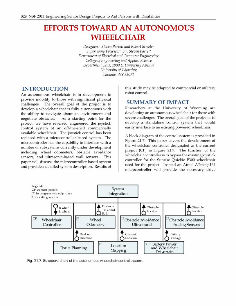
A block diagram of the control system is provided in Figure 21.7. This paper covers the development of the wheelchair controller designated as the current project (CP) in Figure 21.7. The function of the wheelchair controller is to bypass the existing joystick controller for the Sunrise Quickie P300 wheelchair used for the project. Instead an Atmel ATmega164 microcontroller will provide the necessary drive
CP WheelchairController
IP WheelOdometry
IPObstacle AvoidanceUltrasound
IPObstacle AvoidanceAnalog Sensors
IP
Route PlanningIP Location
Mapping
X S Battery Power and Wheelchair
Drivetrain
SystemIntegration
Legend:
CP: cu rrent project
IP: in progress related p rojec t
X S: existin g system
R wheel
L wheel
Distanc e
Trave lled
R, L
Obstacle
Loc ation
Obstacle
Loc ation
Desir ed
Direc tion
Current
Loc ation
Battery
Voltage
Fig. 21.7. Structure chart of the autonomous wheelchair control system.
Chapter 21: University of Wyoming 329
signals to the existing wheelchair drive train (designated XS in Figure 21.7). Other related in progress subsystems are designated by an IP in Figure 21.7. Space does not permit a discussion of other diagrammed subsystems. All of the other subsystems are currently under development as part of the overall research effort.
The concept of a fully autonomous wheelchair is not a new concept. Simpson et al. provides a thorough review of related efforts and work ongoing at the University of Pittsburgh. At the University of Wyoming, Philips has performed an exhaustive study of other related efforts. Also, Hansen has completed a thorough study of related wheelchair guidance and control challenges.
TECHNICAL DESCRIPTION Joystick signals. To develop a microcontroller-based system to substitute for an existing joystick control, the signals issued to the wheelchair drive system by the joystick must be known for various joystick positions. Benson and Philips accomplished similar work. To determine the signal generated by the joystick for various positions, the voltage and current were monitored on the joystick’s X (blue) and Y (white) channel outputs. Results are provided in Figure 21.8.
Several observations are in order relative to these measurements:
• In the neutral position the joystick provides approximately 6 VDC on the X and Y channel.
• The X and Y channels are independent of one another.
• The X channel increases by approximately 0.7 VDC in the forward direction and decreases by the same amount in the reverse direction. The Y channel varies in a similar manner when moved from right to left.
• The control system provides minimal current drain.
• The voltage levels required by the wheelchair drive train (+5.2 to +6.7 VDC) are not directly compatible with standard microcontroller levels (0 and 5 VDC) without interface.
Block Diagram. The block diagram for the wheelchair controller is provided in Figure 21.9. Directional input commands are provided to the controller via four (forward, right, left and reverse) momentary
contact, debounced pushbutton switches. In response to a specific input command, the ATmega164 controller issues the proper analog output signals for the X and Y channels. As previously mentioned, the output voltages range from 5.2 to 6.7 VDC. To achieve these levels from a 5 VDC microcontroller, an analog signal from 0 to 2 VDC is provided via the Serial Peripheral Interface (SPI) fed TLC 5628 digital to analog converter (DAC). The DAC output voltage is summed with a 6 VDC (joystick neutral position voltage) reference and a negative 1.0 VDC bias. The overall result is an output voltage that ranges from 5.0 to 7.0 VDC as required by the joystick controller.
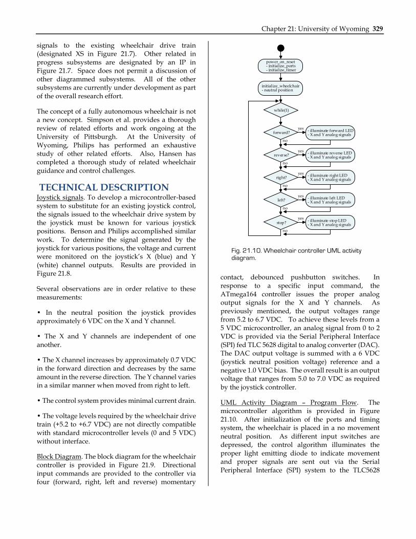
UML Activity Diagram – Program Flow. The microcontroller algorithm is provided in Figure 21.10. After initialization of the ports and timing system, the wheelchair is placed in a no movement neutral position. As different input switches are depressed, the control algorithm illuminates the proper light emitting diode to indicate movement and proper signals are sent out via the Serial Peripheral Interface (SPI) system to the TLC5628
power_on_reset- initialize_ports- initialize_timer
initialize_wheelchair- neutral position
while(1)
forward?
reverse?
right?
left?
stop?
- illuminate forward LED- X and Y analog signals
- illuminate reverse LED- X and Y analog signals
- illuminate right LED- X and Y analog signals
- illuminate left LED- X and Y analog signals
- illuminate stop LED- X and Y analog signals
yes
yes
yes
no
no
no
no
no
yes
yes
Fig. 21.10. Wheelchair controller UML activity diagram.

330 NSF 2011 Engineering Senior Design Projects to Aid Persons with Disabilities
DAC. The program continues to respond to different switch assertions.
Wheelchair interface. The wheelchair interface control is hosted on a 33.0 x 16.5 cm printed circuit board (PCB). The PCB is housed in an aluminum chassis that is under the wheelchair seat. Power for the interface control is provided by a four 9 VDC, 250 mAh Nickel Metal Hydride (NiMH) rechargeable batteries (Tenergy). The batteries are connected in series with the midway point between the batteries grounded to provide a +/- 18 VDC battery supply. The battery output is fed to a series of +/- 12 VDC and +/- 5 VDC regulators required by the analog circuitry and the DAC. The user interface containing the pushbutton switches and LED display are mounted within a small enclosure near the existing joystick. A ribbon cable connects the user interface to the PCB.
We have successfully completed the design of the wheelchair interface controller. The controller has been prototyped and operates correctly for all wheelchair directions. We are in the process of translating the circuit to a PCB design. The PCB design and fabrication is complete. PCB populating and testing is underway. The current drain for the +/- 18 VDC system is 55 mA and 25.6 mA respectively which provides an operational wheelchair time of slightly less than five hours between recharge events. We are investigating an improved battery technology.
This project is the first in a number of related projects toward a fully autonomous wheelchair. It should be emphasized that the pushbutton panel is currently a substitute for an integrated system level controller which will incorporate all other subsystems into a cohesive autonomous system.
ForwardVx: 6.10 VDC @ 26.7 µAVy: 6.66 VDC @ 115 µA
ReverseVx: 6.00 VDC @ 8.0 µA
Vy: 5.20 VDC @ -120 µA
RightVx: 6.77 VDC @ 140 µAVy: 6.00 VDC @ 2.4 µA
LeftVx: 5.23 VDC @ -126 µAVy: 5.95 VDC @ -1.60 µA
NeutralVx: 5.97 VDC @ 2.6 µAVy: 5.98 VDC @ 4.5 µA
Fig. 21.8. Joystick X (blue) and Y (white) channel outputs.
AtmelATmega164
Microcontroller
Wheel Odometer Subsystem
MovementSwitchInputs
SPI- MOSI- SCK
TLC56288-bit Octal
DAC
Analog Interface
Analog Interface
Forward LEDRight LEDLeft LEDReverse LED
+/- 18 VDC +/- 12 VDC
+/- 5 VDC
Forward
Right
Left
Reverse
Left Wheel Encoder Right Wheel Encoder
X
Y
Fig. 21.9. Block diagram of wheelchair controller.
Related Documents