i University of Southern Queensland Faculty of Health, Engineering and Sciences An Investigation into the Testing and Commissioning Requirements of IEC 61850 Station Bus Substations A dissertation submitted by Robert Peter Accendere In fulfilment of the requirements of Courses ENG4111 & ENG4112 Research Project Towards the degree of Bachelor of Power Engineering Submitted: October 2015

Welcome message from author
This document is posted to help you gain knowledge. Please leave a comment to let me know what you think about it! Share it to your friends and learn new things together.
Transcript
i
University of Southern Queensland
Faculty of Health, Engineering and Sciences
An Investigation into the Testing and
Commissioning Requirements of IEC 61850
Station Bus Substations
A dissertation submitted by
Robert Peter Accendere
In fulfilment of the requirements of
Courses ENG4111 & ENG4112 Research Project
Towards the degree of
Bachelor of Power Engineering
Submitted: October 2015

i
Abstract
The emergence of the new IEC 61850 standard generates a potential to deliver a safe, reliable
and effective cost reduction in the way substations are designed and constructed. The IEC
61850 Station Bus systems architecture for a substation protection and automation system is
based on a horizontal communication concept replicating what conventional copper wiring
performed between Intelligent Electronic Devices (IED’s). The protection and control signals
that are traditionally sent and received across a network of copper cables within the
substation are now communicated over Ethernet based Local Area Networks (LAN) utilising
Generic Object Oriented Substation Event (GOOSE) messages.
Implementing a station bus system generates a substantial change to existing design and
construction practices. With this significant change, it is critical to develop a methodology for
testing and commissioning of protection systems using GOOSE messaging. Analysing current
design standards and philosophies established a connection between current conventional
practices and future practices using GOOSE messaging at a station bus level. A potential design
of the GOOSE messaging protection functions was implemented using the new technology
hardware and software. Identification of potential deviations from the design intent,
examination of their possible causes and assessment of their consequences was achieved
using a Hazard and Operability study (HAZOP). This assessment identified the parts of the
intended design that required validating or verifying through the testing and commissioning
process. The introduction of a test coverage matrix was developed to identify and optimise the
relevant elements, settings, parameters, functions, systems and characteristics that will
require validating or verifying through inspection, testing, measurement or simulations during
the testing and commissioning process. Research conducted identified hardware and software
that would be utilised to validate or verify the IEC 61850 system through inspection, testing,
measurement or simulations.
The Hazard and Operability study (HAZOP) has been identified as an effective, structured and
systematic analysing process that will help identify what hardware, configurations, and
functions that require testing and commissioning prior to placing a substation using IEC 61850
Station bus GOOSE messaging into service. This process enables power utilities to understand
new challenges and develop testing and commissioning philosophies and quality assurance
processes, while providing confidence that the IEC 61850 system will operate in a reliable,
effective and secure manner.

ii
Limitations of Use
University of Southern Queensland
Faculty of Health, Engineering and Sciences
ENG4111/ENG4112 Research Project
Limitations of Use
The Council of the University of Southern Queensland, its Faculty of Health, Engineering &
Sciences, and the staff of the University of Southern Queensland, do not accept any
responsibility for the truth, accuracy or completeness of material contained within or
associated with this dissertation.
Persons using all or any part of this material do so at their own risk, and not at the risk of the
Council of the University of Southern Queensland, its Faculty of Health, Engineering & Sciences
or the staff of the University of Southern Queensland.
This dissertation reports an educational exercise and has no purpose or validity beyond this
exercise. The sole purpose of the course pair entitled “Research Project” is to contribute to the
overall education within the student’s chosen degree program. This document, the associated
hardware, software, drawings, and other material set out in the associated appendices should
not be used for any other purpose: if they are so used, it is entirely at the risk of the user.
iii
Certification
I certify that the ideas, designs and experimental work, results, analyses and conclusions set
out in this dissertation are entirely my own effort, except where otherwise indicated and
acknowledged.
I further certify that the work is original and has not been previously submitted for assessment
in any other course or institution, except where specifically stated.
Robert Peter Accendere
0050007098
iv
Acknowledgements
I would like to acknowledge and thank the following people for their support, assistance and
encouragement during this project.
I would like to thank my supervisors Dr Tony Ahfock from USQ and Rob Coggan from Ergon
Energy for providing their technical expertise and guidance. I would like to thank Ergon Energy
and Schneider Electric for providing the software and hardware to develop, build and test the
simulated IEC 61850 substation.
Finally, I would like to thank my beautiful wife Anita and son Logan, for their understanding,
encouragement and support in completing this Degree externally over the last 9 years.
Robert Peter Accendere
University of Southern Queensland
October 2015
v
Table of Contents
ABSTRACT ............................................................................................................................ I
LIMITATIONS OF USE ........................................................................................................... II
CERTIFICATION ................................................................................................................... III
ACKNOWLEDGEMENTS ....................................................................................................... IV
TABLE OF CONTENTS ........................................................................................................... V
LIST OF TABLES ................................................................................................................... IX
LIST OF FIGURES ................................................................................................................. IX
LIST OF ABBREVIATIONS ..................................................................................................... XI
LIST OF STANDARDS ......................................................................................................... XIII
.......................................................................................................................... 1 CHAPTER 1
INTRODUCTION ................................................................................................................... 1
1.1 ERGON ENERGY ............................................................................................................................... 1
1.2 BACKGROUND ................................................................................................................................. 1
1.3 EMERGENCE OF A NEW TECHNOLOGY .................................................................................................. 4
1.3.1 Background of the IEC 61850 Standard .................................................................................. 4
1.3.2 IEC 61850 Standard Systems Architecture .............................................................................. 4
1.3.3 Advantages & Disadvantages of IEC 61850 Standard ............................................................ 6
1.4 PROJECT JUSTIFICATION .................................................................................................................... 8
1.5 PROJECT OBJECTIVES ........................................................................................................................ 8
1.5.1 Resource Requirements .......................................................................................................... 9
........................................................................................................................ 11 CHAPTER 2
LITERATURE REVIEW ......................................................................................................... 11
2.1 SAFETY LEGISLATIONS AND RULES ..................................................................................................... 11
2.2 IEC 61850 STANDARD ................................................................................................................... 12
2.2.1 IEC 61850 Communication Structure – Functions and Models ............................................. 12
2.2.2 IEC 61850 Communication Principles ................................................................................... 13
2.2.3 GOOSE Overview .................................................................................................................. 15
2.2.3.1 What is GOOSE ................................................................................................................. 15
2.2.3.2 Generic Substation Event (GSE) Model ............................................................................ 15
2.2.3.3 GOOSE Message Frame ................................................................................................... 17
2.2.3.4 GOOSE Transfer Times ..................................................................................................... 20
2.2.4 Substation Configuration Language ..................................................................................... 21

vi
2.3 COMMUNICATION TECHNOLOGIES AND TOPOLOGIES ............................................................................ 23
2.3.1 Substation Communication Networks .................................................................................. 23
2.3.2 Substation Ethernet Topologies for IEC 61850 Station Bus .................................................. 23
2.3.3 Network Redundancy ........................................................................................................... 24
2.4 TESTING AND COMMISSIONING OF AN IEC 61850 SUBSTATION ............................................................. 25
2.4.1 IEC 61850 Part 10: Conformance testing .............................................................................. 25
2.4.2 IEC 61850 Edition 2 ............................................................................................................... 25
2.4.2.1 Function Test Mode .......................................................................................................... 25
2.4.2.2 Simulation Mode .............................................................................................................. 26
2.4.3 Conference Publications and Journals .................................................................................. 27
2.5 RISK ASSESSMENT METHODOLOGY ................................................................................................... 28
........................................................................................................................ 30 CHAPTER 3
PROJECT DESIGN METHODOLOGY ...................................................................................... 30
3.1 OVERVIEW ................................................................................................................................... 30
3.2 CURRENT PROTECTION AND CIRCUITRY DESIGN ................................................................................... 30
3.2.1 Overview ............................................................................................................................... 30
3.2.2 Circuit Breaker Failure Protection (CBF) ............................................................................... 31
3.2.3 Sensitive Earth Fault (SEF) Check Scheme ............................................................................ 33
3.2.4 Bus Zone Protection .............................................................................................................. 34
3.2.4.1 High Impedance Bus Zone Protection .............................................................................. 34
3.2.4.2 Low Impedance Bus Zone Protection ............................................................................... 35
3.2.5 Interlocking Schemes ............................................................................................................ 36
3.3 IMPLEMENTATION OF GOOSE MESSAGING AT STATION BUS LEVEL ........................................................ 37
3.3.1 Overview ............................................................................................................................... 37
3.3.2 GOOSE Directional Communication Diagram ....................................................................... 39
3.3.3 GOOSE Protection & Control Matrix ..................................................................................... 40
3.3.4 IED Protection and Control logic ........................................................................................... 41
3.3.5 Substation Configuration Language (SCL) ............................................................................ 42
3.3.6 Station Bus Network Design ................................................................................................. 43
3.3.7 IED Isolation Design .............................................................................................................. 43
3.3.7.1 Current Design and Practices ........................................................................................... 44
3.3.7.2 GOOSE Isolation Design and Practices ............................................................................. 44
........................................................................................................................ 46 CHAPTER 4
RISK ASSESSMENT METHODOLOGY & TEST COVERAGE ...................................................... 46
4.1 RISK ASSESSMENT METHODOLOGY ................................................................................................... 46
4.1.1 Overview ............................................................................................................................... 46
4.1.2 HAZOP Methodology ............................................................................................................ 46
vii
4.1.3 Protection IED Assessment ................................................................................................... 49
4.1.3.1 IED Failure Modes ............................................................................................................ 50
4.1.4 Station Bus Network Assessment ......................................................................................... 50
4.1.4.1 Network Failure Modes .................................................................................................... 51
4.1.5 IEC 61850 Station Bus GOOSE Messaging HAZOP Assessment ............................................ 52
4.1.5.1 Circuit Breaker Fail Protection Scheme ............................................................................ 52
4.2 TEST COVERAGE ............................................................................................................................ 53
4.2.1 Overview ............................................................................................................................... 53
4.2.2 IED & Protection Scheme Test Coverage .............................................................................. 54
4.2.2.1 Conventional IED & Protection Scheme Test Coverage .................................................... 54
4.2.2.2 IEC 61850 IED & Protection Scheme Test Coverage ......................................................... 55
4.2.3 Network Test Coverage ........................................................................................................ 57
........................................................................................................................ 59 CHAPTER 5
LABORATORY SIMULATION & TESTING .............................................................................. 59
5.1 OVERVIEW ................................................................................................................................... 59
5.2 LABORATORY SETUP & HARDWARE ................................................................................................... 59
5.3 TEST EQUIPMENT HARDWARE & SOFTWARE ....................................................................................... 60
5.3.1 Doble F6150 Test Instrument ............................................................................................... 60
5.3.2 Doble Protection Suite & GSE Configurator Tool .................................................................. 62
5.3.3 Wireshark ............................................................................................................................. 63
5.4 11KV FEEDER IED CB FAILURE SIMULATION & TESTING ....................................................................... 64
5.4.1 Overview ............................................................................................................................... 64
5.4.2 Hardware Setup .................................................................................................................... 65
5.4.3 Software Setup ..................................................................................................................... 66
5.4.3.1 GSE Configurator .............................................................................................................. 66
5.4.4 IED CBF Test Results ............................................................................................................. 68
5.5 CIRCUIT BREAKER FAILURE SCHEME SIMULATION & TESTING ................................................................. 69
5.5.1 Overview ............................................................................................................................... 69
5.5.2 CBF Scheme Deploying GOOSE Messaging ........................................................................... 69
5.5.2.1 GOOSE Messaging Hardware Setup ................................................................................. 69
5.5.2.2 GOOSE Messaging Software Setup .................................................................................. 70
5.5.2.3 GOOSE Messaging Test Results ........................................................................................ 71
........................................................................................................................ 73 CHAPTER 6
CONCLUSION .................................................................................................................... 73
6.1 OVERVIEW ................................................................................................................................... 73
6.2 FURTHER WORK ............................................................................................................................ 75
REFERENCES ...................................................................................................................... 76
viii
APPENDIX A: PROJECT SPECIFICATION ............................................................................... 81
APPENDIX B: PROJECT DESIGN SPECIFICATIONS ................................................................. 82
APPENDIX C: CB FAILURE HAZOP ASSESSMENT .................................................................. 91
APPENDIX D: CB FAILURE TEST COVERAGE ......................................................................... 99
APPENDIX E: PROJECT MANAGEMENT & SAFETY ...............................................................102

ix
List of Tables
Table 1: Advantages and Disadvantages of using IEC 61850 ........................................................ 7
Table 2: “Trip” message transfer times as per IEC 61850-5. ...................................................... 21
Table 3: GOOSE Protection and Control Matrix .......................................................................... 41
Table 4: IED Test Performance (Ed 2) ......................................................................................... 45
Table 5: IEC 61882 HAZOP Guide Words for a PES ..................................................................... 48
Table 6: IEC 61882 HAZOP Guide Words for Logical Nodes ....................................................... 48
Table 7: Project Schedule .......................................................................................................... 102
Table 8: DTRMP level of risk matrix .......................................................................................... 103
Table 9: WHS Risk Control Guide .............................................................................................. 103
List of Figures
Figure 1: Electromechanical Distance Relay (Brown Boveri LZ32) ................................................ 2
Figure 2: Protection & Control IEDs .............................................................................................. 3
Figure 3: Architecture of an IEC 61850 System ............................................................................. 5
Figure 4: Typical IEC 61850 Process Level System ........................................................................ 6
Figure 5: IEC 61850 Data Modelling ............................................................................................ 13
Figure 6: IEC 61850 Communication model and communication stack ..................................... 14
Figure 7: GOOSE Model .............................................................................................................. 16
Figure 8: GOOSE Retransmission Scheme ................................................................................... 16
Figure 9: GOOSE message frame as per IEC 61850-8-1 .............................................................. 17
Figure 10: GOOSE Overall Transfer Time as defined in IEC 61850-5 .......................................... 20
Figure 11: SCL Engineering Process ............................................................................................ 22
Figure 12: Station bus network using HSR and PRP protocol ..................................................... 24
Figure 13: Test Mode - Command with Test Mode = False ........................................................ 26
Figure 14: Test Mode - Command with Test Mode = True ......................................................... 26
Figure 15: Edition 2 IED Simulation Mode .................................................................................. 27
Figure 16: Conventional Vs IEC 61850 GOOSE Testing Setup ..................................................... 28
Figure 17: Current Ergon Energy Substation Standard Protection Single Line Diagram ............ 31
Figure 18: Circuit Breaker Fail Logic ............................................................................................ 32
Figure 19: CBF Event on the Substation ...................................................................................... 33
x
Figure 20: SEF Check Protection Scheme Logic........................................................................... 34
Figure 21: High Impedance Bus Zone Protection Scheme .......................................................... 35
Figure 22: Low Impedance Bus Zone Protection Scheme ........................................................... 35
Figure 23: Current Differential Characteristic of a Low Impedance Bus Protection ................... 36
Figure 24: Protection Single Line Diagram Using IEC 61850 Station Bus .................................... 37
Figure 25: Project IEC 61850 Design Process .............................................................................. 38
Figure 26: GOOSE Directional Communication Diagram ............................................................ 40
Figure 27: SET System Configuration .......................................................................................... 43
Figure 28: Conventional Protection Isolation ............................................................................. 44
Figure 29: Flow chart of the HAZOP examination procedure ..................................................... 47
Figure 30: Logical Node Model ................................................................................................... 49
Figure 31: Simplified Protection IED ........................................................................................... 49
Figure 32: HAZOP Examination Template ................................................................................... 52
Figure 33: Data/Control Diagram for CBF Scheme ..................................................................... 53
Figure 34: Microprocessor IED Typical Components .................................................................. 54
Figure 35: Test Bench Physical Hardware Setup ......................................................................... 60
Figure 36: Doble F6150 Front Panel ............................................................................................ 61
Figure 37: Doble Hardware Architecture .................................................................................... 62
Figure 38: Doble F6150 IEC 61850 Configuration Process .......................................................... 63
Figure 39: Wireshark GOOSE Message Capture ......................................................................... 64
Figure 40: IED CB Failure Hardware Setup .................................................................................. 65
Figure 41: GSE Configurator Setup ............................................................................................. 66
Figure 42: GSE Configurator Virtual input setup ......................................................................... 67
Figure 43: Protection Suite Test Plan – GOOSE & Output contact CBF Event ............................ 68
Figure 44: CB Failure GOOSE Message and Output Test Results ................................................ 68
Figure 45: Hardware Setup for CBF Scheme-GOOSE Messaging ................................................ 70
Figure 46: Protection Suite Setup - GOOSE CB Fail Scheme ....................................................... 71
Figure 47: CB Failure Scheme GOOSE Messaging Test Results ................................................... 72
Figure 48: CBF Event Network Traffic Capture ........................................................................... 72

xi
List of Abbreviations
ACSI Abstract Communication Service Interface
A/D Analogue to Digital Converter
CB Circuit Breaker
CBF Circuit Breaker Fail
CID Configured IED Description
CT Current Transformer
CDC CDC Common Data Class
CIM Common Information Model
DT Definite Time
DTRMP Daily Task Risk Assessment Plan
FMEA Failure Mode and Effects Analysis
GSE Generic Substation Event (communication model)
GSSE Generic Substation State Event (communication model)
GOOSE Generic Object Oriented System Event (communication model)
HAZOP Hazard and Operability Studies
HMI Human Machine Interface
IEC International Electrotechnical Commission
I/O Input/Output
ICD IED Capability Description
IED Intelligent Electronic Device
LAN Local Area Networks
LN Logical Node
LPHD Logical node “physical device”
LD LD Logical Device
MAC Media Access Control
NIT Network Interface Card
PC Personal Computer
PD Physical Device
PED Programmed Electronic Device
PES Programmed Electronic System
PSL Programmable Scheme Logic
RTU Remote Terminal Unit
xii
SAS Substation Automation System
SEF Sensitive Earth Fault
SCL System Configuration description Language
SCSM Specific Communication Service Mapping
SSD System Specification Description
SCD Substation Configuration Description
VT Voltage Transformer
VLAN Virtual Local Area Network
XML eXtensible Markup Language

xiii
List of Standards
Standard Title
IEC 61850 Communication networks and systems for power utility automation –
IEC 61850-1 Part 1: Introduction and overview
IEC 61850-3 Part 3: General requirements
IEC 61850-4 Part 4: System and project management
IEC 61850-5 Part 5: Communication requirements for functions and device models
IEC 61850-6 Part 6: Configuration description language for communication in electrical substations related to IEDs
IEC 61850-7-1 Part 7-1: Basic communication structure – Principles and models
IEC 61850-7-2 Part 7-2: Basic information and communication structure – Abstract communication service interface (ACSI)
IEC 61850-7-3 Part 7-3: Basic communication structure – Common data classes
IEC 61850-7-4 Part 7-4: Basic communication structure – Compatible logical node classes and data object classes
IEC 61850-8-1 Part 8-1: Specific communication service mapping (SCSM) – Mappings to MMS (ISO 9506-1 and ISO 9506-2) and to ISO/IEC 8802-3
IEC 61850-10 Part 10: Conformance testing
IEC 61850-90-4 Part 90-4: Network engineering guidelines
IEC 62439 Industrial communication networks – High availability automation networks –
IEC 62439-1 Part 1: General concepts and calculation methods
IEC 62439-3 Part 3: Parallel Redundancy Protocol (PRP) and High-availability Seamless Redundancy (HSR)
AS 2067 Substations and high voltage installations exceeding 1 kV a.c.
AS/IEC 61882 Hazard and operability studies (HAZOP studies)—Application guide
AS/IEC 14763.3 Telecommunications installations — Implementation and operation of customer premises cabling. Part 3: Testing of optical fibre cabling
C37.119 IEEE Guide for Breaker Failure Protection of Power Circuit Breakers
C37.233 IEEE Guide for Power System Protection Testing
1
Chapter 1
Introduction
1.1 Ergon Energy
Ergon Energy supplies electricity across a service area of more than one million square
kilometres, which is equal to 97% of the state of Queensland. With a large geographical area
comes a large operational and capital cost. The electrical supply industry is under increasing
pressure from customers and stakeholders to proactively reduce these costs while providing a
safe, reliable and efficient service. Substations play an integral part of the Ergon Energy
network and are vital for the distribution of electricity. Substations are essential in providing a
connection between power stations, transmission networks, distribution networks and high
voltage customers. Substations have two categories of plant, primary plant and secondary
systems. Primary plant is equipment that is connected directly to the high voltage network
such as high voltage switchgear, power transformer, circuit breakers, and voltage and current
transformers. Secondary systems are equipment used to protect, control and monitor the
primary plant and high voltage feeders leaving or entering the substation. These are typically
protection relays, control and SCADA systems, metering schemes and power quality systems.
One of Ergon Energy’s strategies is focusing on technological innovation to reduce the
operational and capital expenditure for substation infrastructure. Any technology change that
can potentially deliver a safe, reliable and effective cost reduction in the way substations are
designed, constructed, tested, commissioned and during its operation life warrants further
investigation.
1.2 Background
Protection relay and protection schemes play an integral part of Ergon Energy’s secondary
systems. The protection relay function is to detect faults or abnormal operating states on the
power system and to disconnect the faulted equipment and loads in a reliable and timely
manner. The consequences of inadequate protection at any level of the power system can
result in major damage, injury or loss of life, and disruptions to the security and reliability of
supply of the network. There have been enormous changes in protection relay technology over
the last fifty years. Electromechanical relays were the first type of protection relays that
operated on the principle of a mechanical force causing operation of a relay contact in
response to a stimulus. The mechanical forces are generated through current flow in one or
more windings on a magnetic core (Alstom Grid, 2011). All of the protection tripping and

2
backup functions of the protection scheme were performed by additional auxiliary relays and
circuitry. Figure 1 illustrates an electromechanical distance relay.
Figure 1: Electromechanical Distance Relay (Brown Boveri LZ32)
In the early 1960’s electromechanical relays were eventually replaced with static relays which
eliminated the use of moving parts and their design was based on the use of analogue
electronic devices and discrete devices such as transistors and diodes in conjunction with
resistors, capacitors, inductors. In the 1980’s digital protection relays were developed and the
change in technology introduced microprocessors, microcontrollers and A/D conversion for all
measured analogue magnitudes and to implement and perform protection algorithms and
digital logic. Manufacturers of these relays introduced proprietary communication protocols
used to communicate between the protection relays and the manufacturers controls systems.
With the introduction of this additional technology, introduced challenges with designing of
substations, where only proprietary manufacturer’s hardware could be used or additional
media converters were required. In the early 1990’s numerical protection relays were
developed due to advances in digital signal processor (DSP) technology and specialised
microprocessors that enabled functions and mathematical algorithms to be processed at
optimum speeds. With each change in the relay technology brought a reduction in the size of
the protection relay and an improvement in functionality and reliability due to their superior
microprocessors and self-monitoring functions. This enabled designers to reduce the required
auxiliary relays and circuitry within the protection schemes and allowed these functions to be
engineered within the protection relay. During these significant technological advances in
3
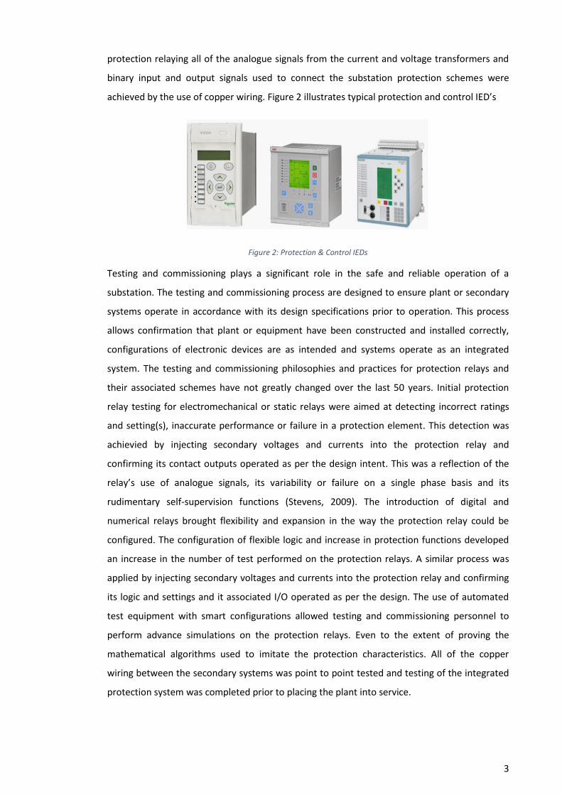
protection relaying all of the analogue signals from the current and voltage transformers and
binary input and output signals used to connect the substation protection schemes were
achieved by the use of copper wiring. Figure 2 illustrates typical protection and control IED’s
Figure 2: Protection & Control IEDs
Testing and commissioning plays a significant role in the safe and reliable operation of a
substation. The testing and commissioning process are designed to ensure plant or secondary
systems operate in accordance with its design specifications prior to operation. This process
allows confirmation that plant or equipment have been constructed and installed correctly,
configurations of electronic devices are as intended and systems operate as an integrated
system. The testing and commissioning philosophies and practices for protection relays and
their associated schemes have not greatly changed over the last 50 years. Initial protection
relay testing for electromechanical or static relays were aimed at detecting incorrect ratings
and setting(s), inaccurate performance or failure in a protection element. This detection was
achievied by injecting secondary voltages and currents into the protection relay and
confirming its contact outputs operated as per the design intent. This was a reflection of the
relay’s use of analogue signals, its variability or failure on a single phase basis and its
rudimentary self-supervision functions (Stevens, 2009). The introduction of digital and
numerical relays brought flexibility and expansion in the way the protection relay could be
configured. The configuration of flexible logic and increase in protection functions developed
an increase in the number of test performed on the protection relays. A similar process was
applied by injecting secondary voltages and currents into the protection relay and confirming
its logic and settings and it associated I/O operated as per the design. The use of automated
test equipment with smart configurations allowed testing and commissioning personnel to
perform advance simulations on the protection relays. Even to the extent of proving the
mathematical algorithms used to imitate the protection characteristics. All of the copper
wiring between the secondary systems was point to point tested and testing of the integrated
protection system was completed prior to placing the plant into service.
4
1.3 Emergence of a New Technology
1.3.1 Background of the IEC 61850 Standard
In 1986, the Electrical Power Research Institute (EPRI) launched the Utility Communication
Architecture (UCA) project. The objective of this project was to decrease the expenditure in
substation automation systems (SAS) and the integration of an open architecture and a
selection of standard protocols that will meet the engineering requirements of power utilities
and accepted by substation automation systems (SAS) manufacturers. In 1995, the
International Electrotechnical Commission’s (IEC) initiated a project called 61850. This project
was designed to define the next generation of standardized high-speed substation control and
protection communications. The main objective of this project was to develop a standard for
communications infrastructure for substation control, monitoring and protection with input
from both substation automation systems (SAS) manufacturers and power utilities. In 1996,
both EPRI and the IEC 61850 develop groups were independently developing their individual
standards to address the interoperability of different manufacturers IED’s in substation
protection and automation systems. In 1997, the ERPI joined forces with the International
Electrotechnical Commission’s (IEC) Technical Committee 57 (TC57) to build a single worldwide
accepted standard. The objectives of the standard are:
Provide interoperability between IED’s from different manufacturers
IED’s self-description capabilities and communication parameters
High speed communication for the required applications
Reduction in conventional wiring in the substation.
Conformance testing requirements for IEC 61850 IED’s
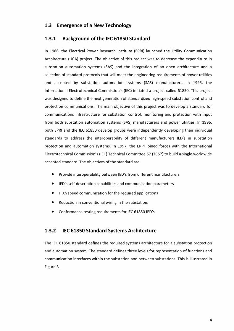
1.3.2 IEC 61850 Standard Systems Architecture
The IEC 61850 standard defines the required systems architecture for a substation protection
and automation system. The standard defines three levels for representation of functions and
communication interfaces within the substation and between substations. This is illustrated in
Figure 3.
5
Station
Bus
IED’s for Protection
& Control
Primary Plant
Interface IED’s/
Merging Units
Gateway
Communication to
Control Center
HMI/Local
SCADA
Network
Switch
Process Bus
IEC 61850 9-2
Process Level
Bay Level
Station Level
Figure 3: Architecture of an IEC 61850 System
The Station Level devices consist of the substations remote gateway, Human Machine
Interface (HMI) and remote interrogation station. Within the substation control status, process
and supervisory control data and monitoring data is exchanged between the Bay/Unit Level
and Station Level. The Station Level communications and exchanges control, status and
monitoring data between the substation and control centre.
The Bay Level devices consist of protection, control and monitoring IED’s. These devices are
connected to the Station Level (via the station bus) and Process Level (via the process bus)
using Ethernet based Local Area Networks (LAN) and Ethernet switches. The station bus
exchanges data within the bay level that can be used for protection, control status, process
and supervisory control data and monitoring data. The station bus can also be used to
interface between substations for exchange of protection and control data. GOOSE messaging
can be utilised on the station bus for fast reliable control and time critical protection
applications between bay level IED’s.
The Process Level devices consist of remote I/O’s, non-conventional instrument transformers
and intelligent sensors and control units from switchgear, transformers and monitoring
devices. These devices are connected to the bay level via the process bus. The voltage

6
transformers (VT) and current transformers (CT) that are connected to the process bus are
connected via an IED called a “Merging Unit”. This is illustrated in Figure 4. The Merging Units
samples the conventional CT and VT analogue outputs and converts the values to a digital
signal referred to as “Sample Values”. The Merging Unit digital output is defined in IEC 61850-
9-2.
Figure 4: Typical IEC 61850 Process Level System (Tournier & Werner, 2010)
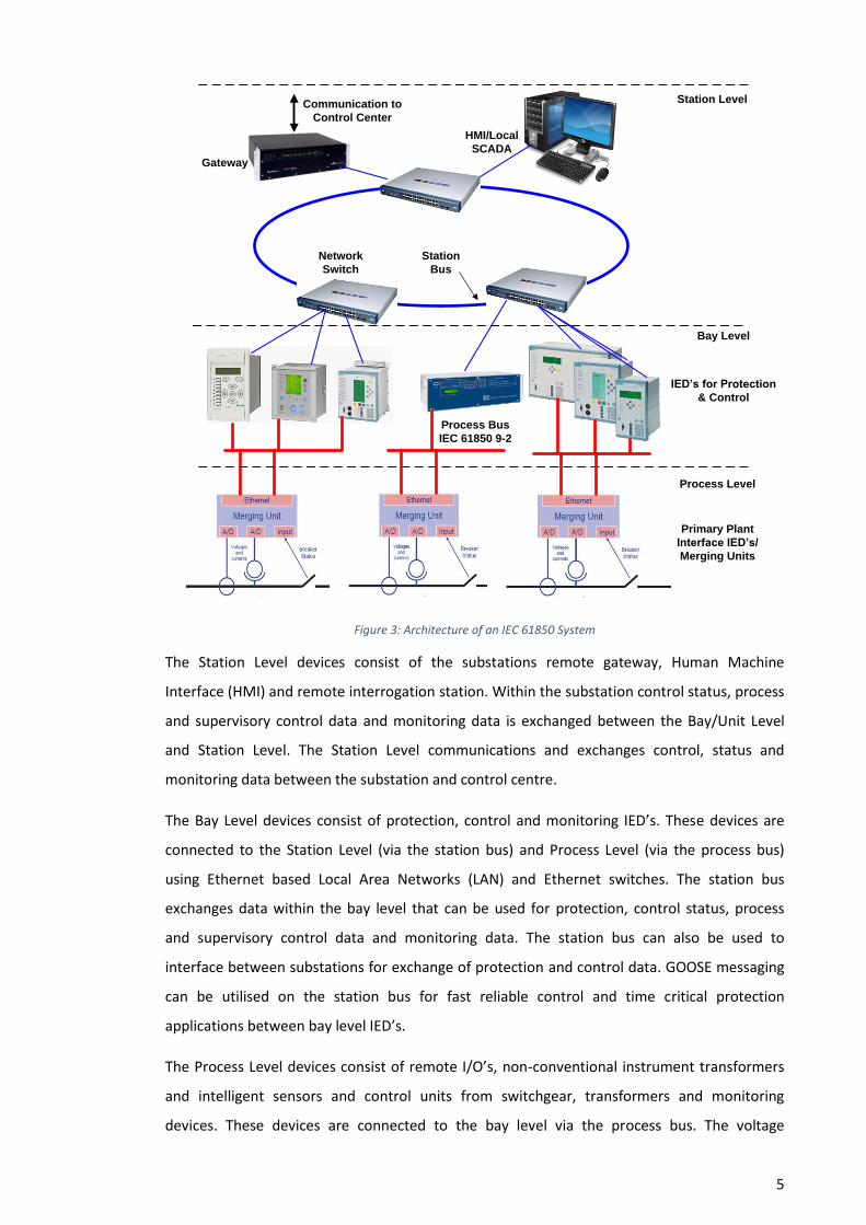
1.3.3 Advantages & Disadvantages of IEC 61850 Standard
There are a number of advantages and disadvantage of using the IEC 61850 standard in
substation protection and automation systems. The advantages of using such systems have
been highly publicised by IED manufactures, while the disadvantages can only be compared
with current substation protection and automation systems. Table 1 provides an overview of
the advantages and disadvantages of using IEC 61850.
7
ADVANTAGES
A reduction of copper cabling and wiring between the substation primary plant and secondary systems
An increase in functionality in a single IED and a reduction in auxiliary relays.
A reduction in relays and wiring allows for additional space inside of the substation
Interoperability between IED’s from different manufactures
A reduction in the substation footprint with the use of fibre optic sensors (NCIT) instead of conventional measuring transformers
A decrease in electrical interference of signal using fibre optic cables
GOOSE signals are supervised, where equivalent hard wired signals between IED's provide no or limited supervision of connection. The subscribing IED's monitor the GOOSE message from the publishing IED. An IED failure or network failure will result in the subscribing IEDs enabling a GOOSE failure alarm.
An increase in safety since there will be no risk of inadvertent opening of current transformer secondary circuits while they are in service.
Simplified engineering process with the use of the substation configuration language and standard system configuration tools and decrease in manual configurations. A decrease in circuitry design.
DISADVANTAGES
Initial increase in cost to develop new substation design and protection standards for the company.
An increase in Cyber security threats due to the increase use of communication networks
A loss of communication or data on the process or station bus may delay or prevent the operation of protection function.
A huge change in the skill sets on personnel that design, construct and test substation protection and automation systems
Table 1: Advantages and Disadvantages of using IEC 61850
8
1.4 Project Justification
Majority of the time new technology is introduced into the system with the concept of
increasing safety and reliability while reducing operational and capital expenditure. The
emergence of the new IEC 61850 standards brings this potential saving in the design and
construction of a substation. On site testing and commissioning plays, a critical role in ensuring
that the substation protection schemes meet their intended design and the systems operate as
an integrated system prior to operation. Due to the significant change in the way an IEC 61850
substation and automation system is designed and constructed with the potential of having no
copper wiring between the primary and secondary systems, current testing and commissioning
philosophies and practices need to be reviewed. A full understanding of the new SAS systems
hardware, configurations, functions and the requirements, if any to validate or verify the
intended design through inspection, testing, measurement or simulations during the testing
and commissioning process is essential. This is more relevant than ever before since the
protection systems have changed from an electromechanical relay to a digital relay with
conventional analogue inputs and binary I/O using copper wiring to digital software based and
communication network orientated protection schemes. Only a structured and systematic
analysing process will help identify what hardware, configurations, and functions that require
testing prior to commissioning a substation using IEC 61850 Station bus GOOSE messaging.
1.5 Project Objectives
The aim of this project is to investigate and provide a better understanding of the methods and
technical requirements to safety, reliably and efficiently test and commission and place in
service a substation using IEC 61850 Station bus GOOSE messaging. This will provide a future
reference and reasoning on what and why certain functions and components of a protection
system using GOOSE messaging are tested and commissioned.
The key objectives of this research project are as follows:
1. To carry out a literature review relating to the IEC 61850 and IEC 62439 standards,
Current Safety Legislations and National Electricity Rules regarding testing,
commissioning and operating a substation, Current standards and technical papers
and case studies written regarding the testing and commissioning of an IEC 61850
station bus substations. A literature review on risk assessment methodology of highly
dependable software based systems and programmed electronic systems to identify
potential systems that could be used to analyse the IEC 61850 station bus system
validation and verification requirements.
9
2. Identify the configuration tools, test equipment and software used for the design,
testing and commissioning of an IEC 61850 station bus substation using GOOSE
messaging.
3. Analyse the protection functions that could potentially be used in the implementation
of an IEC 61850 station bus substation and the test required for verifying associated
IED’s logic/protection functions that uses the GOOSE messaging.
4. Analyse the site integration test required for verifying the station bus network,
protection inter-tripping schemes. Investigate the protection isolation requirements
for an operational IEC 61850 station bus substation using GOOSE messaging.
5. Analyse IED’s logic/protection functions that uses the GOOSE messaging within an IEC
61850 station bus substation against conventional protection relay logic/protection
functions.
6. Develop a substation utilising IEC 61850 station bus GOOSE messaging and examine
the methods, practices and technical requirements for testing an IEC 61850 station bus
substation.
1.5.1 Resource Requirements
There are a number of resources required to complete this project. Majority of the resources
will be essential for the testing of the IED’s and the station bus network. Due to the expense
of the IEC 61850 hardware and software, only a small network with limited IED’s will be setup.
The hardware (IED’s & Ethernet Switches) for the project have been provided by Ergon Energy
substation standards group and IED manufacturer Schneider. The system and IED configuration
tool used for the development of the IED Files (SSD, ICD, SCD, CID) will be provided by
Schneider. This tool is currently a BETA version of their SET system configuration tool. The IEC
61850 compatible secondary injection test set, test leads and interface software will be
provided by Ergon Energy’s test section. Ergon Energy’s protection group will provide the
manufacturer IED configuration tools. Ergon Energy’s Substations standards group will provide
the network analysing software and tools for examining the station bus GOOSE traffic. Below is
a breakdown of the required hardware and software.
Required Hardware:
IED’s. (2 x Micom P142, 1 x Micom P642, 1 x P746, 1 x P140)
2 x 2520 CISCO Communication Switches
Fibre Optic Cable for connection between IED’s and Switches
Doble Test Set & Test Leads
Laptop and required serial leads for communication to IED’s
10
Required Software:
Schneider’s System Configuration Tool SET (BETA Version)
Micom S1 studio
Doble Protection Suite & IEC61850 GSE 3.2 Configurator Tool
Wireshark software
11
Chapter 2
Literature Review
This chapter will provide the findings of a Literature Review that is aimed to increase the
knowledge and understanding in the following areas.
Current Safety Legislations and National Electricity Rules that Network Service Provider
and/or electricity entities need to follow for testing, commissioning and operating a
substation.
Relevant parts of the IEC 61850 standard regarding the communication principles,
communication structure (functions and models), GOOSE messaging, and Substation
Configuration Language.
Communication technologies and topologies used in an IEC 61850 protection and
automation system and IEC 62439 Industrial communication networks – High
availability automation networks, in particular part 3 of the standard that defines the
implementation of redundancy protocols for critical network systems.
Current standards and technical papers and case studies written regarding the testing
and commissioning of an IEC 61850 protection and automation system using station
bus.
Risk assessment methodology of highly dependable software based systems and
programmed electronic systems.
2.1 Safety Legislations and Rules
The following Queensland legislations and National Electricity Rules were reviewed to
determine the requirements by law on the requirements in testing and commissioning of a
substation protection and control system and during its operational life.
Queensland Electrical Safety Act 2002
Queensland Electrical Safety Regulation 2013
Electrical Safety Code of Practice 2013
Queensland Work Health and Safety Act 2011
Queensland Work, Health and Safety Regulation 2011
National Electricity Rules version 61
AS 2067 Substations and High Voltage Installations exceeding 1 kV A.C

12
The review identified that the National Electricity Rules states that a Network Service Provider
like Ergon Energy must institute and maintain a compliance program to ensure the proper
operation of protection systems and control systems that may affect power system security
and the safe and reliable operation of equipment (AEMO, 2015). The Queensland Electrical
Safety Act 2011 states that electricity entity like Ergon Energy has a duty to ensure that its
works are electrically safe and operate in a way that is electrically safe. These duties include
the requirement that the electricity entity inspect, test and maintain these works (Electical
Safety Act, 2002).
The current revision of AS 2067-2008 section 9 provides the minimum requirements for the
inspection and testing of Substations and High Voltage Installations exceeding 1 kV A.C. The
standard recommends that verification should be achieved utilising visual inspection,
functional tests and measuring. The standard does not provide any specific details or
recommendations on testing and commissioning of protection schemes utilising IEC 61850.
The standard recommends that functional test, verification of settings and circuitry and
programming, verification of operation and configuration by measurement or testing of
protective, monitoring, measuring and control devices should be carried out prior to service
(Australian Standard - AS 2067, 2008).
2.2 IEC 61850 Standard
2.2.1 IEC 61850 Communication Structure – Functions and Models
The IEC 61850 standard defines information models and the modelling methods to ensure the
open exchange of information between any of the substation IED’s. The IEC 61850 information
model is based on two levels of modelling. The first is the breakdown of a physical device (IED)
into a logical device (LD), second is the breakdown of the logical device into logical nodes (LN),
data objects, and attributes. The logical devices provide information about the physical
devices they use as host. The physical device (IED) is connected to the network by a network
address. The IED’s hardware health and communication problems are modelled at the physical
device level. The logical device represents a group of typical protection and automation
functions within the IED. To achieve interoperability amongst IED’s, common functions in a
power utility automation system have been identified and have been split into sub-functions
known as logical nodes. The IEC 61850-7 series defines a collection of standard logical nodes,
object classes and attributes used for protection, control, monitoring, measurement and
power quality systems. Figure 5 shows an example of the IEC 61850 data model. In this
example the logical device has two logical nodes. Logic node MMXU1 is defined in IEC 61850-5
as a 3 phase measurement logical node used for calculation of currents, voltages, powers and
13
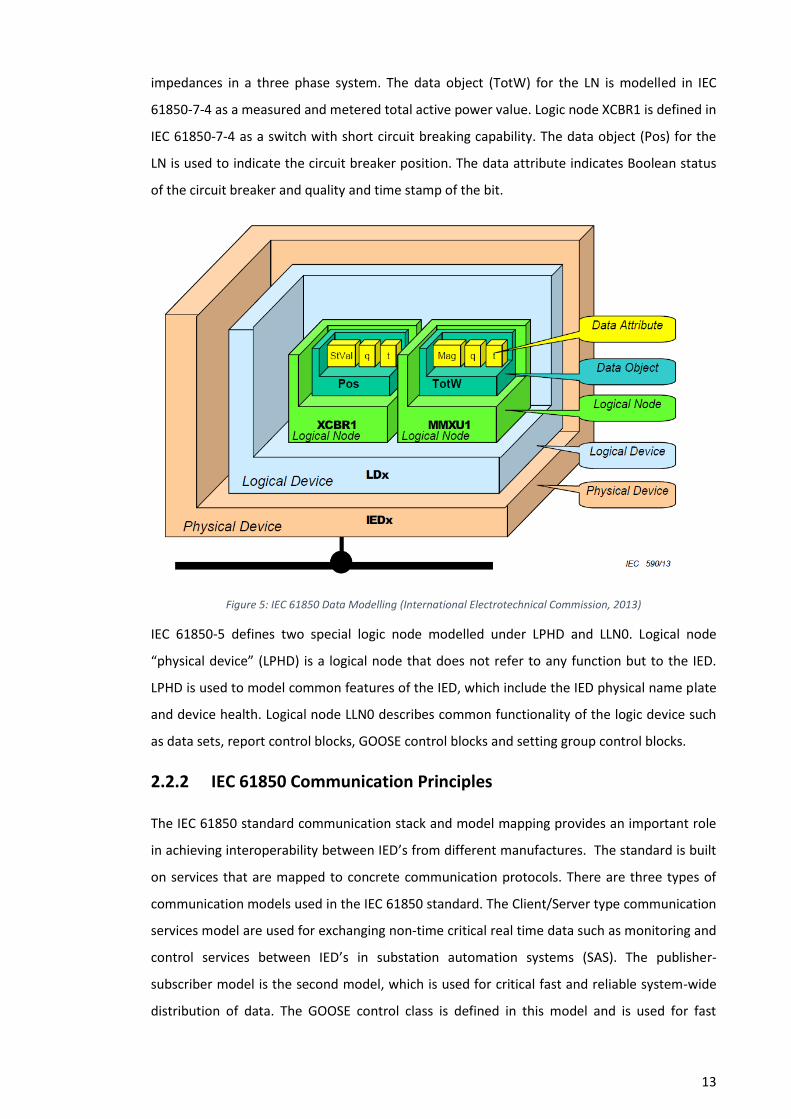
impedances in a three phase system. The data object (TotW) for the LN is modelled in IEC
61850-7-4 as a measured and metered total active power value. Logic node XCBR1 is defined in
IEC 61850-7-4 as a switch with short circuit breaking capability. The data object (Pos) for the
LN is used to indicate the circuit breaker position. The data attribute indicates Boolean status
of the circuit breaker and quality and time stamp of the bit.
Figure 5: IEC 61850 Data Modelling (International Electrotechnical Commission, 2013)
IEC 61850-5 defines two special logic node modelled under LPHD and LLN0. Logical node
“physical device” (LPHD) is a logical node that does not refer to any function but to the IED.
LPHD is used to model common features of the IED, which include the IED physical name plate
and device health. Logical node LLN0 describes common functionality of the logic device such
as data sets, report control blocks, GOOSE control blocks and setting group control blocks.
2.2.2 IEC 61850 Communication Principles
The IEC 61850 standard communication stack and model mapping provides an important role
in achieving interoperability between IED’s from different manufactures. The standard is built
on services that are mapped to concrete communication protocols. There are three types of
communication models used in the IEC 61850 standard. The Client/Server type communication
services model are used for exchanging non-time critical real time data such as monitoring and
control services between IED’s in substation automation systems (SAS). The publisher-
subscriber model is the second model, which is used for critical fast and reliable system-wide
distribution of data. The GOOSE control class is defined in this model and is used for fast

14
protection tripping between IED’s. The third model is Sample Values (SMV) model for multicast
measurement values. This model is used for exchanging time critical voltage and current data
on to the process bus. Figure 6 illustrates the IEC 61850 communication model and
communication stack according to the ISO/OSI model. The Client/Server type communication
service uses MMS (Manufacturing Message Specification) at the Application (layer 7),
Presentation (layer 6) and Session (layer 5) layers. The Transport (layer 4) and Network (layer
3) layers use TCP/IP while the Link (layer 2) and Physical (layer 1) layers uses Ethernet. The
GOOSE and Sample Values (SMV) model are mapped directly to the Link (layer 2) and Physical
(layer 1) layers using Ethernet to enable time critical data transfer.
Figure 6: IEC 61850 Communication model and communication stack (Midence & Iadonis, 2009)
The IEC 61850-7-2 standard defines a set of abstract communication services (Abstract
Communication Service Interface services – ACSI) which details the required actions on the
receiving and sending of a service request. This allows for compatible exchange of information
between IEDs on substation automation systems (SAS). Part 8 of the standard specifies the
method for exchanging time critical and non-time critical data through LANs by mapping the
ACSI to MMS (Manufacturing Message Specification) and ISO/IEC 8802-3 frames. Services and
protocols of the TCP/IP T-Profile client/server are detailed in Part 8 of the standard. The direct
mapping on Ethernet is detailed in Part 9-2 of the standard.
15
2.2.3 GOOSE Overview
2.2.3.1 What is GOOSE
Generic Object Oriented Substation Event (GOOSE) messages were develop as part of the
standard for fast reliable control and protection applications. The GOOSE messaging is based
on a publisher-subscriber model where the GOOSE message is broadcasted on a multicast
Media Access Control (MAC) address by the publisher IED and the subscribing IED’s listen for
messages that are of interest. The model was constructed under the concept of decentralized
and autonomous distribution. This process would ensure any equipment, independently of its
location can provide a GOOSE message delivery simultaneously to more than one host on a
Local Area Network (LAN), using multicast (Oliveira, et al., n.d.). The GOOSE messaging is based
on a horizontal communication concept replicating what conventional copper wiring
performed between IED’s. The protection and control applications that were traditionally sent
and received across a network of copper cables are now communicated over Ethernet based
Local Area Networks (LAN). Time critical protection functions like protection inter-tripping,
primary plant interlocking and status indications, auto-reclosing and trip signals can now be
implemented and achieved using GOOSE messaging.
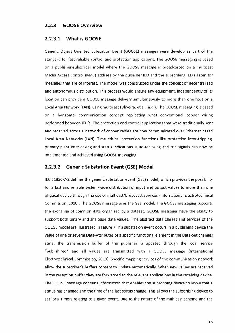
2.2.3.2 Generic Substation Event (GSE) Model
IEC 61850-7-2 defines the generic substation event (GSE) model, which provides the possibility
for a fast and reliable system-wide distribution of input and output values to more than one
physical device through the use of multicast/broadcast services (International Electrotechnical
Commission, 2010). The GOOSE message uses the GSE model. The GOOSE messaging supports
the exchange of common data organized by a dataset. GOOSE messages have the ability to
support both binary and analogue data values. The abstract data classes and services of the
GOOSE model are illustrated in Figure 7. If a substation event occurs in a publishing device the
value of one or several Data-Attributes of a specific functional element in the Data-Set changes
state, the transmission buffer of the publisher is updated through the local service
“publish.req” and all values are transmitted with a GOOSE message (International
Electrotechnical Commission, 2010). Specific mapping services of the communication network
allow the subscriber’s buffers content to update automatically. When new values are received
in the reception buffer they are forwarded to the relevant applications in the receiving device.
The GOOSE message contains information that enables the subscribing device to know that a
status has changed and the time of the last status change. This allows the subscribing device to
set local timers relating to a given event. Due to the nature of the multicast scheme and the
16
absence of the addressing layer for the straight mapping of the GOOSE message, there is no
confirmation by the subscriber that the GOOSE message has been received successfully.
Figure 7: GOOSE Model (Zhang & Nair, 2008)
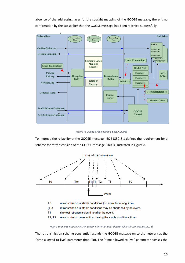
To improve the reliability of the GOOSE message, IEC 61850-8-1 defines the requirement for a
scheme for retransmission of the GOOSE message. This is illustrated in Figure 8.
Figure 8: GOOSE Retransmission Scheme (International Electrotechnical Commission, 2011)
The retransmission scheme constantly resends the GOOSE message on to the network at the
“time allowed to live” parameter time (T0). The “time allowed to live” parameter advises the
17
receiving IED of the maximum time to wait for the next re-transmission. If the receiving IED
does not receive the message in the retransmission time, the IED assumes that the message is
lost. If an event occurs in a relay and there is a state change in the dataset, the stable
condition retransmission time will be shortened ((t0)) and the “time allowed to live” time is
shorted (T1). This allows for a rapid spray of GOOSE messages onto the network. After this
short burst of messages, the retransmission time increases gradually until it reaches its
configurable value (T0). Although this scheme enables an increase in reliability due to the
increased frequency of the message during an event, the scheme does increase the amount of
traffic on the network after a significant event (Oliveira, et al., n.d.).
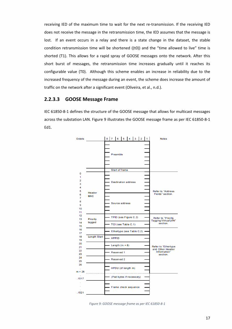
2.2.3.3 GOOSE Message Frame
IEC 61850-8-1 defines the structure of the GOOSE message that allows for multicast messages
across the substation LAN. Figure 9 illustrates the GOOSE message frame as per IEC 61850-8-1
Ed1.
Figure 9: GOOSE message frame as per IEC 61850-8-1
18
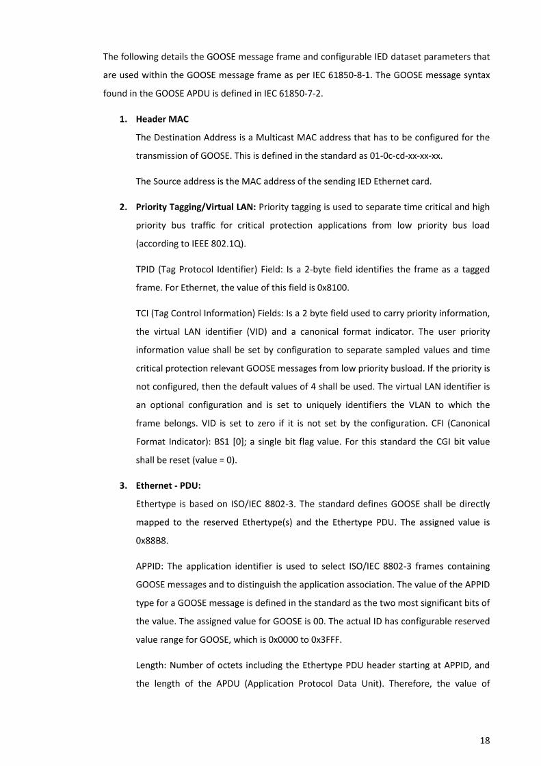
The following details the GOOSE message frame and configurable IED dataset parameters that
are used within the GOOSE message frame as per IEC 61850-8-1. The GOOSE message syntax
found in the GOOSE APDU is defined in IEC 61850-7-2.
1. Header MAC
The Destination Address is a Multicast MAC address that has to be configured for the
transmission of GOOSE. This is defined in the standard as 01-0c-cd-xx-xx-xx.
The Source address is the MAC address of the sending IED Ethernet card.
2. Priority Tagging/Virtual LAN: Priority tagging is used to separate time critical and high
priority bus traffic for critical protection applications from low priority bus load
(according to IEEE 802.1Q).
TPID (Tag Protocol Identifier) Field: Is a 2-byte field identifies the frame as a tagged
frame. For Ethernet, the value of this field is 0x8100.
TCI (Tag Control Information) Fields: Is a 2 byte field used to carry priority information,
the virtual LAN identifier (VID) and a canonical format indicator. The user priority
information value shall be set by configuration to separate sampled values and time
critical protection relevant GOOSE messages from low priority busload. If the priority is
not configured, then the default values of 4 shall be used. The virtual LAN identifier is
an optional configuration and is set to uniquely identifiers the VLAN to which the
frame belongs. VID is set to zero if it is not set by the configuration. CFI (Canonical
Format Indicator): BS1 [0]; a single bit flag value. For this standard the CGI bit value
shall be reset (value = 0).
3. Ethernet - PDU:
Ethertype is based on ISO/IEC 8802-3. The standard defines GOOSE shall be directly
mapped to the reserved Ethertype(s) and the Ethertype PDU. The assigned value is
0x88B8.
APPID: The application identifier is used to select ISO/IEC 8802-3 frames containing
GOOSE messages and to distinguish the application association. The value of the APPID
type for a GOOSE message is defined in the standard as the two most significant bits of
the value. The assigned value for GOOSE is 00. The actual ID has configurable reserved
value range for GOOSE, which is 0x0000 to 0x3FFF.
Length: Number of octets including the Ethertype PDU header starting at APPID, and
the length of the APDU (Application Protocol Data Unit). Therefore, the value of
19
Length shall be 8 + m, where m is the length of the APDU and m is less than 1492.
Frames with inconsistent or invalid length field shall be discarded.
4. GOOSE APDU:
State Number (stNum): Is a counter that increments if a GOOSE message is generated
as a result of an event change within a dataset.
Sequence Number (sqNum): Is a counter that increment if a GOOSE message has been
sent.
Test/Simulation: This Boolean value is used for testing and simulation purposes. A true
value indicates that the device is in test mode and the subscribing devices will not use
the GOOSE message for operational purposes because the message has been
published from a simulation unit.
Time Allowed to Live (TAL): This is the maximum time a packet remains alive on the
network after transmission.
Needs Commissioning (NdsCom): This value is set to true if the GoCB requires further
configurations and the GOOSE message is invalid.
Configuration Revision (confRev): This value represents a count on the number of
times the Data-Set configuration has changed. The IED is responsible for incrementing
this parameter and is an attribute of ConfRev of the GoCB.
Number of Data-Set Entries (numDatSetEntries): This value indicates the number of
data present in the received GOOSE message.
GOOSE Control Block Reference (GoCBRef): This parameter details the name of the
referenced GOOSE control block (GoCB).
Data-Set (DatSet): This parameter contains the object reference attributes (name) of
GOOSE Data-Set identification in the publishing IED and the Logic Node (LN).
GOOSE ID (GoID): This parameter is a user definable identification of the GOOSE
message.
Timestamp (t): This value contains the time at which a GOOSE message is generated as
a result of an event change within a dataset.
GOOSE Data (GOOSEData): This parameter contains the information defined in the
dataset members that will be sent by the GOOSE message.

20
2.2.3.4 GOOSE Transfer Times
IEC 61850-5 defines the transfer times, message type and performance classes for a GOOSE
message. The GOOSE transfer time of a message is specified as the complete transmission time
from one physical device transmission stack (coding and sending) to another physical device
transmission stack (receiving and decoding). This overall transmission time consist of the
individual times of the stack processing (ta, tc) and of the network transfer time (tb). The
network transfer time (tb) includes waiting times and time delays caused by routers and other
active communication devices being part of the complete communication path (International
Electrotechnical Commission, 2013). The transfer time does not include the sending and
receiving processing time of the functions (f1 & f2). Figure 10 illustrates the described GOOSE
transfer times.
Figure 10: GOOSE Overall Transfer Time as defined in IEC 61850-5
IEC 61850-5 describes seven classes for transfer times. The GOOSE messages use the Type 1 –
Fast messages performance class P1, P2 and P3. This type of message is used for time critical
functions like protection. Type 1 messages contain simple messages such as “Trip”, “Block”,
“Unblock”, and “Close”. The IED receiving the message will enable its related function to
immediately operate, ensuring critical protection times are achieved on the network. The Type
1A “Trip” performance class P1 and P2 are used for protection trip messages in the substation.
Type 1A messages are also used for interlocking, inter-trips and logic discrimination between
protection functions. Table 2 details the Type 1A “Trip” message transfer times as per IEC
61850-5.

21
Performance Class
Requirement Description Transfer Time
Class ms
P1 The total transmission time shall be below the order of a quarter of a cycle (5ms for 50HZ)
TT6 ≤ 3
P2 The total transmission time shall be below the order of a half of a cycle (10ms for 50HZ)
TT5 ≤ 10
Table 2: “Trip” message transfer times as per IEC 61850-5.
2.2.4 Substation Configuration Language
To provide interoperability between IED’s from different manufactures, a standardized support
for system design and communication engineering was required. IEC 61850 part 6 specifies a
file format for describing communication-related IED configurations and IED parameters,
communication system configurations, switch yard (function) structures, and the relations
between them (International Electrotechnical Commission, 2009). This file format enables the
exchange of the IED capability descriptions and substation automation system (SAS)
description between IED engineering tools and the system engineering tools. The language
used to support the exchange of these capabilities and descriptions is called the System
Configuration description Language (SCL). The SCL language is based on eXtensible Markup
Language (XML) and the describing of the IED configurations and substation automation
system (SAS) is achieved according to IEC 61850-5 and IEC 61850-7. There are four types of SCL
files defined under the IEC 61850 and each SCL file contains the following part, which is,
defined under IEC 61850-6 clause 9.
Clause 9.1: A header that is used to identify an SCL file and its version/revision history.
Clause 9.2: The substation description section in the SCL file is used to define the functional
structure of a substation and to identify the primary device and their electrical connections.
Clause 9.3: The IED description section describes the pre-configuration of an IED. The
description contains the IED communication services, access points, logical devices and logical
nodes.
Clause 9.4: The communication system description section describes the communication
connection between IED access points and common subnetwork or logical busses.
Clause 9.5: The Data type templates contains the instantiable template of the data of a logical
node that is built from data object elements.
22
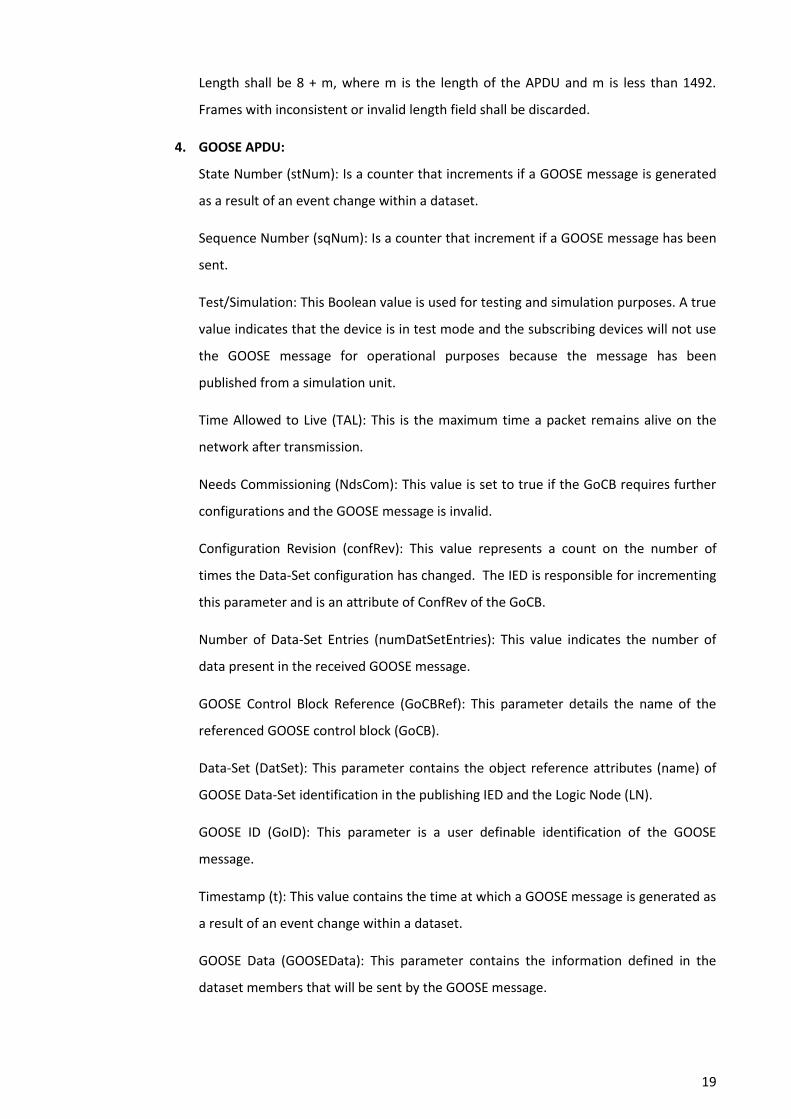
The four different SCL files (SSD, SCD, ICD, CID) and configurators defined under the IEC 61850-
6 standard is implemented in different stages of the designing and configuration process of the
substation automation system (SAS). This Engineering process is illustrated in Figure 11.
Figure 11: SCL Engineering Process (Apostolov, 2010)
The first step of the engineering process is the use of the system specification tools. This tool
enables the user to describe the substation protection and automation system. This includes
the substation single line diagram and the functional requirements represented by logical
nodes (Apostolov, 2008). The SCL file created from the system specification tools is a system
specification description, which has an .SSD file extension. The next step in the process is to
create an IED Capability Description (ICD) file for each IED that will be connected to the
substation protection and automation system. This is achieved using an IED configurator tool
and is normally a manufacturer’s proprietary software tool. The ICD file contains the default
functionality of an IED and the information on the capabilities and data model of each
individual IED. The IED description contains communication services related capabilities of the
IED, the configurator related capabilities of an IED (Data sets or control blocks) and the
functionality and data objects in terms of logic nodes and contain data objects (Wimmer &
Wolfgang, 2005). The ICD file is imported to the system configuration tool. The system
configuration tool is used to import or export configuration files defined by IEC 61850-6 and is
used for the engineering of the communication system level. All of the substation IED’s ICD
files and the substation SSD file are imported into the system configuration tool. The system
configurator is used to configure the data exchange between IED’s and communication
parameters for the substation protection and automation system. The system configurator is

23
also used to configure the GOOSE messages by specifying the senders (publishers) and the
receivers (subscribers) of messages (Aguilar & Ariza, 2010). The substation protection and
automation system configuration is now represented by the system configuration description
(SCD) file. The next step in the engineering process is to export the configured IED description
(CID) files from the system configurator. The CID file represents a single IED section of the SCD
file and contains the address and specified names used in the SCD system. The CID file for each
IED can be loaded into each IED using an IED configurator tool. The IED is now configured for
its designed purpose in the substation protection and automation system.
2.3 Communication Technologies and Topologies
2.3.1 Substation Communication Networks
The backbone of an IEC 61850 substation protection and automation system is the
communication network. Prior to the IEC 61850 standard, majority of the communication
between substation protection and automation devices were performed by proprietary serial
communication systems to communicate control and monitoring functions of the substation.
With the introduction of time critical protection functions onto the substations protection and
automation system, a high degree of reliability, dependability and deterministic behaviour
would be vital for the substation communication networks (Yadav & Kapadia, 2010). Both the
station and process bus in an IEC 61850 substation is based on industrial Ethernet technology.
Ethernet was chosen due to its cost effective, high speeds, and its high degree of flexibility
with regards to the communication architecture (Wimmer & Wolfgang, 2005). Ethernet is a
simple layer 2 protocol and makes use of flexible communication devices such as switches and
routers.
2.3.2 Substation Ethernet Topologies for IEC 61850 Station Bus
The IEC 61850 standard does not specify any independent Ethernet network topology.
Ethernet Local Area Networks (LANs) in an IEC 61850 substation protection and automation
system can be built and configured using any physical topologies like trees, stars or rings. The
network also has the capability to carry both station and process bus traffic. Ethernet Rings
and Ethernet Redundant Trees are the two main topologies commonly used by network
manufacturers implementing IEC 61850 substation protection and automation systems due to
their superior physical redundancy. L Zhang & N.C. Nair (2008) performed test to measure the
transmission speed of the GOOSE message on a station bus between four IED’s from the same
manufacturer using star, peer-to peer and ring topologies. The research identified that the

24
different topologies did not make significant difference on transmission times of the GOOSE
message.
2.3.3 Network Redundancy
Redundancy of the station bus network is the most important function of the network. A high
degree of reliability is critical for protection functions carried on the station bus network. A
failure to a time critical protection message on the communication network could potentially
cause safety and reliability issues to the greater transmission or distribution network. IEC
62439 Industrial communication networks – High availability automation networks defines the
requirements for substations protection and automation system network redundancy
solutions. IEC 62439 series considers two classes of network redundancy. Redundancy
managed within the network and redundancy managed in the end nodes. Part 3 of the
standard defines two redundancy protocols that are specifically designed for station bus IED’s.
The first is the Parallel Redundancy Protocol (PRP) where the node is connected to two
different redundant networks and the node chooses independently the network to use
(Kirrmann., et al., 2008). The second is High-availability Seamless Redundancy (HSR) protocol,
where the nodes are solely connected the network and the network provides redundancy
through links and switches. Both protocols provide static network redundancy mechanism and
provides seamless switchover during failures to communication links and switches (Midence &
Iadonis, 2009). Figure 12 illustrates a station bus network using HSR and PRP protocol.
Figure 12: Station bus network using HSR and PRP protocol (Kirrmann., et al., 2008)

25
2.4 Testing and Commissioning of an IEC 61850 Substation
2.4.1 IEC 61850 Part 10: Conformance testing
Part 10 of the IEC 61850 specifies standard techniques for testing of conformance of client,
server and sampled value devices and engineering tools, as well as specific measurement
techniques to be applied when declaring performance parameters (International
Electrotechnical Commission , 2012). The details of the testing are under a laboratory
environment with only two IED’s connected onto the test network. This part of the standard is
intended mainly for IEC 61850 developers and allows insurance that the device or tool operate
correctly and is fully supported as per the standard. This allows the integrator of an IEC 61850
substation protection and control system confidence that each device work as intended.
2.4.2 IEC 61850 Edition 2
Edition 2 of the IEC 61850 standard was developed to fix technical issues, improve
inconsistencies and clarify interoperability encountered from different IED manufacturers
under Edition 1. The second edition of the standard provides new functionalities and
enhancements that could potentially be utilised during the testing and commissioning of an
IEC 61850 substation. Some of these additional features have the potential to be used as
mechanisms for in service protection isolation.
2.4.2.1 Function Test Mode
IEC 61850 Edition 2 part 7-4 defines the behaviour of an IED in response to test signals while
set in test mode. IEC 61850 Edition 2 IED’s have the capability to set a logical node or a logical
device into test mode using the data object Mod of the LN or of LLN0. Figure 13 illustrates the
behaviour of the IED with the test flag set to “FALSE”. A command to operate the IED can be
initiated by a GOOSE message or control operation that is interpreted by the subscriber as a
command (Apostolov, 2015). With the test mode of the IED disabled, a command initiated
with the test flag set to “FALSE” and the function (logical node or logical device) is “ON”, the
IED will behaviour as normal. This will include the operation the IED’s physical or virtual
outputs. GOOSE messages emanating from devices under test will not be processed by the IED.
If the IED is set to test mode, any commands that are received will not be executed by the IED.
Including the operation the IED’s physical or virtual outputs.
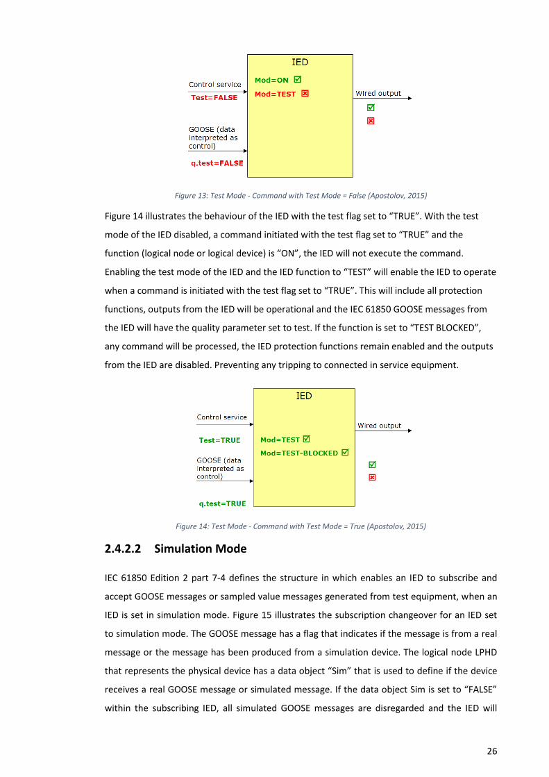
26
Figure 13: Test Mode - Command with Test Mode = False (Apostolov, 2015)
Figure 14 illustrates the behaviour of the IED with the test flag set to “TRUE”. With the test
mode of the IED disabled, a command initiated with the test flag set to “TRUE” and the
function (logical node or logical device) is “ON”, the IED will not execute the command.
Enabling the test mode of the IED and the IED function to “TEST” will enable the IED to operate
when a command is initiated with the test flag set to “TRUE”. This will include all protection
functions, outputs from the IED will be operational and the IEC 61850 GOOSE messages from
the IED will have the quality parameter set to test. If the function is set to “TEST BLOCKED”,
any command will be processed, the IED protection functions remain enabled and the outputs
from the IED are disabled. Preventing any tripping to connected in service equipment.
Figure 14: Test Mode - Command with Test Mode = True (Apostolov, 2015)
2.4.2.2 Simulation Mode
IEC 61850 Edition 2 part 7-4 defines the structure in which enables an IED to subscribe and
accept GOOSE messages or sampled value messages generated from test equipment, when an
IED is set in simulation mode. Figure 15 illustrates the subscription changeover for an IED set
to simulation mode. The GOOSE message has a flag that indicates if the message is from a real
message or the message has been produced from a simulation device. The logical node LPHD
that represents the physical device has a data object “Sim” that is used to define if the device
receives a real GOOSE message or simulated message. If the data object Sim is set to “FALSE”
within the subscribing IED, all simulated GOOSE messages are disregarded and the IED will

27
continue utilising the real messages. If the data object Sim is set to “TRUE”, the subscribing IED
will utilise the simulated messages within its internal processing. The subscribing IED continues
to use the real GOOSE 1 message until the first simulated GOOSE 1 message is received by the
subscribing IED. When the simulated message is received, the IED ignores any further real
GOOSE 1 messages. The IED continues to process the real GOOSE 2 and 3 messages. The data
object SimSt (simulation status) within the logical node LGOS (GOOSE subscription monitoring)
provides indication when the particular subscription has successfully switched over to a
simulation source. The simulated GOOSE 1 message will continue to be processed until the
LPHD.Sim.stval parameter is changed to “FALSE”.
Figure 15: Edition 2 IED Simulation Mode (Alstom Grid, 2015)
2.4.3 Conference Publications and Journals
Apostolov (2008) discussed the test system architecture and principles for the testing of
individual devices using sample values and protection schemes that involve multiple IED
devices. Apostolov (2008) splits the principles of testing into functional and system testing.
Functional testing applies a top-down method of verification of any function or sub function
and ensuring the tested element has the expected behaviour under different realistic test
conditions. Valid or invalid inputs should be provided to the functions and the expected output
for each test condition defines the results. Compared to system testing which evaluates the
overall performance of the system.

28
Apostolov & Vandiver (2007) functional testing of IEC 61850 base protection relays paper
discusses a high level comparison between testing conventional based protection relays with
protection relays using IEC 61850 station bus technology. Figure 16 illustrates the difference
between the two technologies. The test device for conventional IED functional testing
simulates the substation current and voltage signals, binary (opto) inputs and the IED outputs
through hard-wired interface. The IED outputs are measured to detect the operational
performance of the IED against its specified design. Function testing of an IED using GOOSE
messaging has the same approach expect the inputs and outputs between the test device and
the IED are simulated and monitored through the station bus network. Apostolov & Vandiver
(2007) discusses that its good practice to monitor and compare the operation of an IED’s
output and a GOOSE message driven by the same functional element in the IED logic.
Figure 16: Conventional Vs IEC 61850 GOOSE Testing Setup (Apostolov & Vandiver, 2007)
Kanabar & Parikh (2011) described the importance of GOOSE integration and communication
network configuration verification testing. Verification test were achieved using the wireshark
tool to capture the GOOSE message over the network and check the data fields of the
message. Verification of the Ethernet switched network was essential using a network analyser
to confirm the MAC address of all connected devices as well Multicast domains (VLAN) of
Ethernet switches.
2.5 Risk Assessment Methodology
CIGRE working group B5.32 (2009) discuss the importance of test coverage during testing.
Their recommendation is to implement the Hazard and Operability Studies (HAZOP) or Failure
29
Mode and Effects Analysis (FMEA) risk assessment methodologies for identifying potential
functional and component failures and possible physical and logical node failures to systems.
The working group describes physical components like IED’s and switches as typically
programmed electronic devices (PED), while logical nodes are treated as black boxes and their
failure modes are limited to loss or degradation of an expected behaviour. Logic nodes are
defined by IEC 61850 as having all of the properties of a programmed electronic system (PES)
and therefor the guide words used by IEC 61882 for a PES can be utilised for a HAZOP
assessment on an IEC 61850 logical node.
Fenelon & Hebbron (2007) discusses the increasing use of HAZOP for analysing programmable
electronic systems and the starting point for a HAZOP study is the deviation from the design
intent. Once identified the HAZOP then aims to identify potential causes (faults) and
consequences (System-level failure modes) of that deviation. The system allows the use of
protection, detection and indicating mechanisms to identify possible potential causes (faults)
and consequences (System-level failure modes). Fenelon & Hebbron (2007) describes the
HAZOP methodology particularly useful for identifying weaknesses in systems.
Pentti & Helminen (2002) describes the use of FMEA as an important procedure by which each
potential failure mode in a system is analysed to determine the results or effects thereof on
the system and to classify each potential failure mode according to its severity. Pentti &
Helminen (2002) discusses the use of FMEA in safety-critical software-based automation and
industrial automation systems and provides examples for its use to perform a functional
approach that recognizes that every item is designed to perform a number of outputs. The
outputs are listed and their failures analysed.
30
Chapter 3
Project Design Methodology
3.1 Overview
With only a handful of small IEC 61850 substations commissioned and placed into service in
Australia, with majority of them designed, constructed, tested and commissioned by IED
manufactures like ABB and SIEMENS. It is critical to develop a design methodology to
understand the design rules and specifications to implement GOOSE messaging on a station
bus network. The project design methodology will use a top down engineering approach to
critically analysis the following.
3.2 Current Protection and Circuitry Design
3.2.1 Overview
Ergon Energy currently has a number of design standards for implementation of new and
refurbishment substation projects. All of these standard designs utilise the use of conventional
protection relays, Remote Terminal Units (RTU), conventional primary plant (CT’s and VT’s)
and hard copper wiring between secondary systems and primary plant. It is critical to
understand Ergon Energy’s current protection and circuitry design philosophies to be able to
establish a connection between current practices and future practices using GOOSE messaging
at a station bus level. This section will identify and describe the protection and interlocking
functions that could potential be implemented utilising GOOSE messaging at a station bus
level. A simplified substation protection single line diagram using Ergon Energy’s current
substation standards and conventional infrastructure is illustrated in Figure 17.
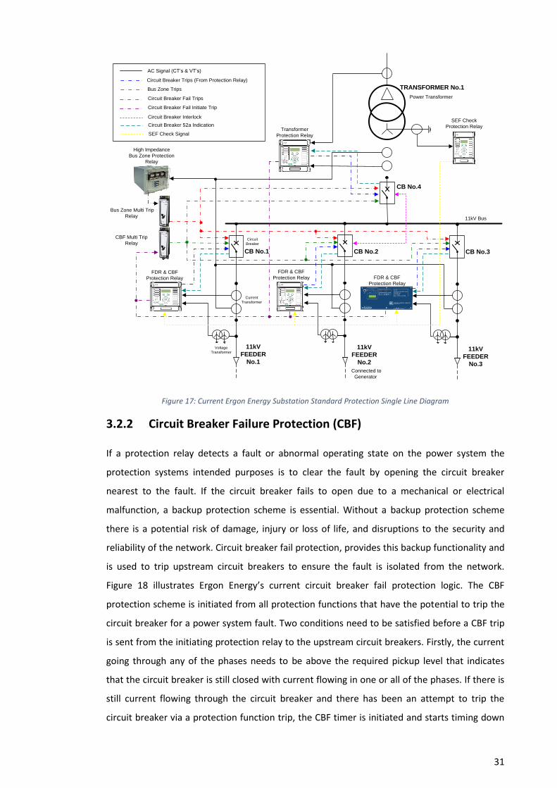
31
AC Signal (CT’s & VT’s)
Current
Transformer
Voltage
Transformer
High Impedance
Bus Zone Protection
Relay
Bus Zone Multi Trip
Relay
CBF Multi Trip
Relay
FDR & CBF
Protection Relay
FDR & CBF
Protection Relay
Transformer
Protection Relay
Power Transformer
Connected to
Generator
11kV Bus
FDR & CBF
Protection Relay
Circuit
Breaker
Circuit Breaker Trips (From Protection Relay)
Bus Zone Trips
Circuit Breaker Fail Trips
Circuit Breaker Fail Initiate Trip
Circuit Breaker Interlock
TRANSFORMER No.1
CB No.4
CB No.2 CB No.3CB No.1
11kV
FEEDER
No.1
11kV
FEEDER
No.2
11kV
FEEDER
No.3
Circuit Breaker 52a IndicationSEF Check
Protection Relay
SEF Check Signal
Figure 17: Current Ergon Energy Substation Standard Protection Single Line Diagram
3.2.2 Circuit Breaker Failure Protection (CBF)
If a protection relay detects a fault or abnormal operating state on the power system the
protection systems intended purposes is to clear the fault by opening the circuit breaker
nearest to the fault. If the circuit breaker fails to open due to a mechanical or electrical
malfunction, a backup protection scheme is essential. Without a backup protection scheme
there is a potential risk of damage, injury or loss of life, and disruptions to the security and
reliability of the network. Circuit breaker fail protection, provides this backup functionality and
is used to trip upstream circuit breakers to ensure the fault is isolated from the network.
Figure 18 illustrates Ergon Energy’s current circuit breaker fail protection logic. The CBF
protection scheme is initiated from all protection functions that have the potential to trip the
circuit breaker for a power system fault. Two conditions need to be satisfied before a CBF trip
is sent from the initiating protection relay to the upstream circuit breakers. Firstly, the current
going through any of the phases needs to be above the required pickup level that indicates
that the circuit breaker is still closed with current flowing in one or all of the phases. If there is
still current flowing through the circuit breaker and there has been an attempt to trip the
circuit breaker via a protection function trip, the CBF timer is initiated and starts timing down

32
from its settable value. If the protection function and current check elements are still high
after the CBF timer expires, a trip will be initiated from the CBF relay or function to the
upstream circuit breakers, which in turn will clear the fault on the power system.
≥ 1
TRIP
CB
≥ 1
CURRENT CHECK APH
CURRENT CHECK BPH
CURRENT CHECK CPH
&
T CBF
0
CBF TIMER
CURRENT CHECK ELEMENTS
CBF TRIP OUTPUT
51PT OR 51GT
87
67P1T OR 67G1T
CIRCUIT BREAKER FAIL LOGIC/FUNCTION
CIRCUIT BREAKER TRIP
LOGIC/FUNCTION
Figure 18: Circuit Breaker Fail Logic
Figure 19 Illustrates a typically CBF scenario on the simplified substation configuration. If
Feeder No.1 has a fault on its distribution cable, circuit breaker (CB) No.1 is designed to trip
and open and will clear the fault from the network. If the fault is still present and circuit
breaker No.1 fails to open within the settable CBF time and the current is above the settable
current check threshold, a CBF event will occur. The remaining circuit breakers connected to
the 11kV bus will need to trip. This is achieved using copper cabling and auxiliary relays. When
the CBF trip output are initiated from the No.1 11kV Feeder protection relay, the signal is sent
to the 11kV bus circuit breaker failure multi trip relay. The multi trip relay is energise and it’s
normally closed contacts will close and a trip signal will be sent to all of the 11kV circuit
breakers on that particular 11kV bus. This will remove the fault from the network. As shown in
Figure 19, CB No.2, CB No.3 and CB No.4 will trip.

33
AC Signal (CT’s & VT’s)
Current
Transformer
Voltage
Transformer
CBF Multi Trip
Relay
FDR & CBF
Protection Relay
FDR & CBF
Protection Relay
Transformer
Protection Relay
Power Transformer
Connected to
Generator
11kV Bus
FDR & CBF
Protection Relay
Circuit Breaker Fail Trips
Circuit Breaker Fail Initiate Trip
TRANSFORMER No.1
CB No.4
CB No.2 CB No.3CB No.1
11kV
FEEDER
No.1
11kV
FEEDER
No.2
11kV
FEEDER
No.3
SEF Check
Protection Relay
FAULT
Circuit Breaker Trips (From Protection Relay)
Figure 19: CBF Event on the Substation
3.2.3 Sensitive Earth Fault (SEF) Check Scheme
A large majority of earth faults on the distribution network are high impedance in nature
because of the resistivity of the return ground path. If conductors fall down onto a road or into
a tree there is a potential of having limited earth fault current and the standard earth fault
element of the protection relay will not operate. Ergon Energy currently use a Sensitive Earth
Fault (SEF) check protection scheme that allows the protection to trip for low current earth
faults and is independent to the IDMT earth fault protection function within the protection
relay. The protection scheme uses a current checking functionality via a SEF check relay that
measures the return current in the substation power transformer neutral connection. If the
current flowing in the neutral of the transformer is above the SEF check pickup current setting,
the SEF check relay will initiate a SEF check output, which will in turn energise the SEF auxiliary
relay. The SEF auxiliary relay normally closed contacts will open and the SEF check input to all
of the 11kV feeder protection relays will change to a low state. This is sent to every 11kV
protection relay on the connected 11kV high voltage bus via separate copper cabling. If the SEF
input is low on the 11kV feeder protection relay, the SEF is armed and the stage one definite
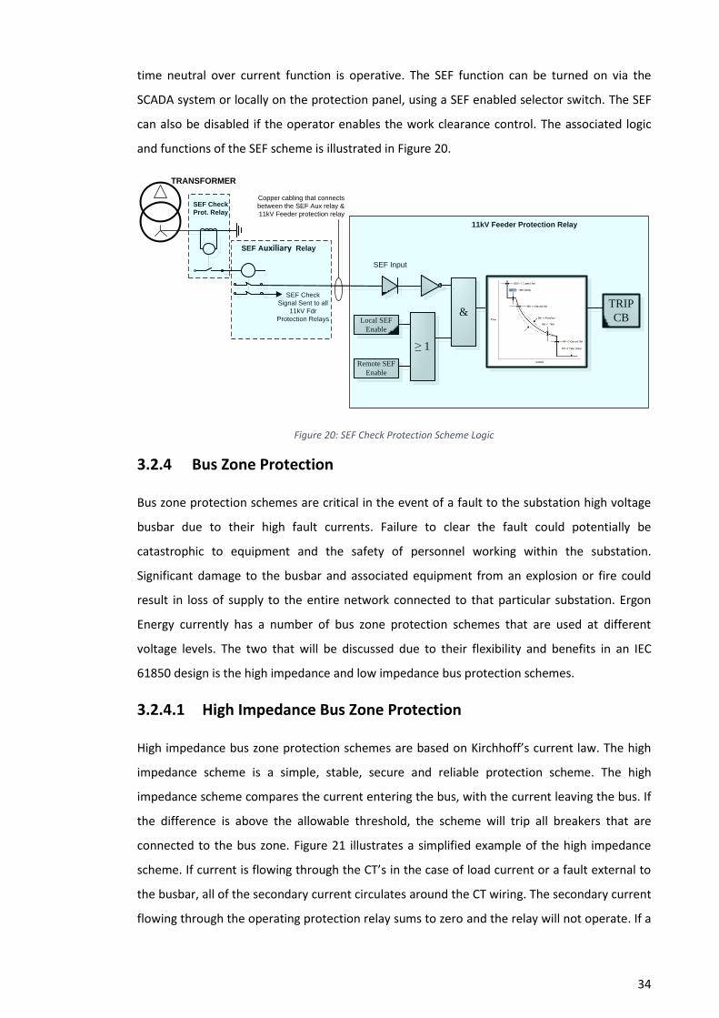
34
time neutral over current function is operative. The SEF function can be turned on via the
SCADA system or locally on the protection panel, using a SEF enabled selector switch. The SEF
can also be disabled if the operator enables the work clearance control. The associated logic
and functions of the SEF scheme is illustrated in Figure 20.
≥ 1
TRIP
CB&
Local SEF
Enable
Remote SEF
Enable
TRANSFORMER
SEF Input
SEF Check
Prot. Relay
SEF Auxiliary Relay
SEF Check
Signal Sent to all
11kV Fdr
Protection Relays
11kV Feeder Protection Relay
Copper cabling that connects
between the SEF Aux relay &
11kV Feeder protection relay
Figure 20: SEF Check Protection Scheme Logic
3.2.4 Bus Zone Protection
Bus zone protection schemes are critical in the event of a fault to the substation high voltage
busbar due to their high fault currents. Failure to clear the fault could potentially be
catastrophic to equipment and the safety of personnel working within the substation.
Significant damage to the busbar and associated equipment from an explosion or fire could
result in loss of supply to the entire network connected to that particular substation. Ergon
Energy currently has a number of bus zone protection schemes that are used at different
voltage levels. The two that will be discussed due to their flexibility and benefits in an IEC
61850 design is the high impedance and low impedance bus protection schemes.
3.2.4.1 High Impedance Bus Zone Protection
High impedance bus zone protection schemes are based on Kirchhoff’s current law. The high
impedance scheme is a simple, stable, secure and reliable protection scheme. The high
impedance scheme compares the current entering the bus, with the current leaving the bus. If
the difference is above the allowable threshold, the scheme will trip all breakers that are
connected to the bus zone. Figure 21 illustrates a simplified example of the high impedance
scheme. If current is flowing through the CT’s in the case of load current or a fault external to
the busbar, all of the secondary current circulates around the CT wiring. The secondary current
flowing through the operating protection relay sums to zero and the relay will not operate. If a
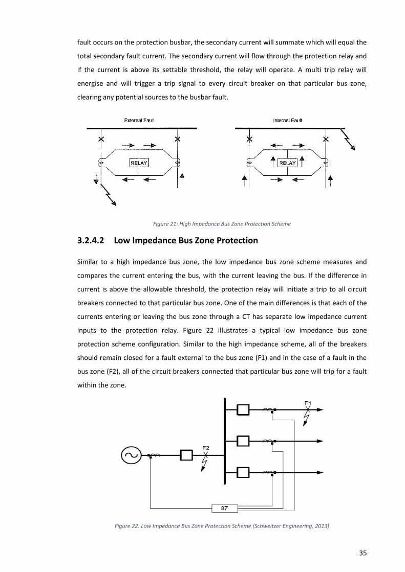
35
fault occurs on the protection busbar, the secondary current will summate which will equal the
total secondary fault current. The secondary current will flow through the protection relay and
if the current is above its settable threshold, the relay will operate. A multi trip relay will
energise and will trigger a trip signal to every circuit breaker on that particular bus zone,
clearing any potential sources to the busbar fault.
Figure 21: High Impedance Bus Zone Protection Scheme
3.2.4.2 Low Impedance Bus Zone Protection
Similar to a high impedance bus zone, the low impedance bus zone scheme measures and
compares the current entering the bus, with the current leaving the bus. If the difference in
current is above the allowable threshold, the protection relay will initiate a trip to all circuit
breakers connected to that particular bus zone. One of the main differences is that each of the
currents entering or leaving the bus zone through a CT has separate low impedance current
inputs to the protection relay. Figure 22 illustrates a typical low impedance bus zone
protection scheme configuration. Similar to the high impedance scheme, all of the breakers
should remain closed for a fault external to the bus zone (F1) and in the case of a fault in the
bus zone (F2), all of the circuit breakers connected that particular bus zone will trip for a fault
within the zone.
Figure 22: Low Impedance Bus Zone Protection Scheme (Schweitzer Engineering, 2013)

36
The protection relay operates using its sophisticated algorithms to vectorially sum the
normalized currents from all individual current inputs to calculate the differential current (Iop )
in the bus zone. The algorithm also arithmetically sums the current magnitudes to create a
restraint current (IRT ). Figure 23 illustrates a typical current differential characteristic of a low
impedance bus protection relay. The differential current (Iop ) is compared with the restraint
current (IRT ). If the differential current (Iop ) exceeds the threshold above the characteristic
curve, the protection has identified that an internal bus fault is present and will operate,
tripping the circuit breakers connected to that particular bus zone. The main advantage of
using a low impedance scheme is the flexibility of the configurations due to the
microprocessor-based technology. CT inputs to the relay can be set to different ratios and
polarity, where in high impedance schemes they need to set the same to ensure the current
summate correctly. Multiple bus protection zones can be set using isolator or circuit breaker
status in conjunction with the flexible logic within the protection relay.
Figure 23: Current Differential Characteristic of a Low Impedance Bus Protection (Schweitzer Engineering, 2013)
3.2.5 Interlocking Schemes
Interlocking schemes play a vital role in ensuring high voltage equipment is operated correctly.
Majority of interlocking schemes are designed to protect the operator of the equipment and
prevents the operator from performing an incorrect sequence of manoeuvres. The interlocking
is achieved using the switching mechanisms and in the electrical control circuits of the circuit
breaker. It is critical to have interlocking on high voltage circuit breakers that are connected to
embedded generation. The interlocking scheme ensures the generator is isolated from Ergon
Energy’s network by its high voltage distribution circuit breaker when the main sub-
transmission supply is isolated from the substation. This ensures that the network does not
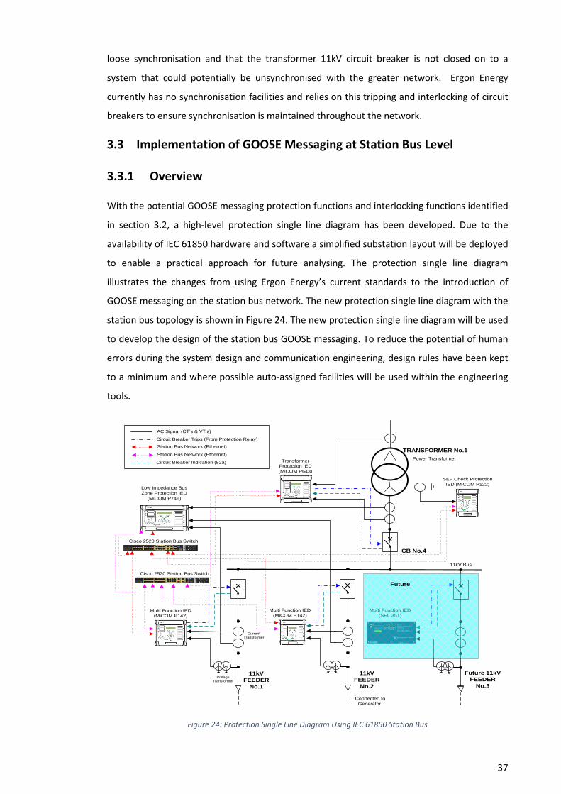
37
loose synchronisation and that the transformer 11kV circuit breaker is not closed on to a
system that could potentially be unsynchronised with the greater network. Ergon Energy
currently has no synchronisation facilities and relies on this tripping and interlocking of circuit
breakers to ensure synchronisation is maintained throughout the network.
3.3 Implementation of GOOSE Messaging at Station Bus Level
3.3.1 Overview
With the potential GOOSE messaging protection functions and interlocking functions identified
in section 3.2, a high-level protection single line diagram has been developed. Due to the
availability of IEC 61850 hardware and software a simplified substation layout will be deployed
to enable a practical approach for future analysing. The protection single line diagram
illustrates the changes from using Ergon Energy’s current standards to the introduction of
GOOSE messaging on the station bus network. The new protection single line diagram with the
station bus topology is shown in Figure 24. The new protection single line diagram will be used
to develop the design of the station bus GOOSE messaging. To reduce the potential of human
errors during the system design and communication engineering, design rules have been kept
to a minimum and where possible auto-assigned facilities will be used within the engineering
tools.
AC Signal (CT’s & VT’s)
Current
Transformer
Voltage
Transformer
Low Impedance Bus
Zone Protection IED
(MiCOM P746)
Multi Function IED
(MiCOM P142)
Transformer
Protection IED
(MiCOM P643)
11kV Bus
Multi Function IED
(SEL 351)
Circuit Breaker Trips (From Protection Relay)
Station Bus Network (Ethernet)
Multi Function IED
(MiCOM P142)
Cisco 2520 Station Bus Switch
Station Bus Network (Ethernet)
Connected to
Generator
CB No.4
11kV
FEEDER
No.1
11kV
FEEDER
No.2
Future 11kV
FEEDER
No.3
Circuit Breaker Indication (52a)Power Transformer
TRANSFORMER No.1
SEF Check Protection
IED (MiCOM P122)
Future
Cisco 2520 Station Bus Switch
Figure 24: Protection Single Line Diagram Using IEC 61850 Station Bus

38
The first step of the design process will be developing a GOOSE direction communication
diagram detailing the directions of the datasets from each IED. This will provide an overview of
the IED’s that will be publishing and subscribing to each other over the network. A GOOSE
Protection and Control matrix will be developed detailing each IEDs publishing and subscribing
datasets and the GOOSE Data items within each dataset. This will provide a logical approach
for specifying the senders (publishers) and the receivers (subscribers) of messages. This will
also allow Ergon Energy’s current protection logic configuration files to be modified to enable
the use of GOOSE messaging within the logic, instead of using conventional opto inputs and
contact outputs in the design. Generic pickup and timer values will be used for the settable
protection functions such as CB fail current pickup and timers. The modified logic and setting
files will need to be loaded into the IEDs using their manufacturer’s proprietary software. The
second step of the design process is to create the required IEC 61850 configuration files for
each IED. This process will follow the steps as shown in Figure 25.
System Configurator
(SET)
- Publishing/subscribing of
LN within datasets
- Communication Engineer
(MAC addresses, VLAN)
IED Database
IED Capabilities
(LN, DO)
.ICD
.SCD
System Configuration
Description (Relationship,
communication parameters,
publishing/subscribing
- Assigning of GOOSE message to IED internal
addesses
IED Configurator
.CID
Configured IED Description
(publishing/subscribing
mapping to internal
address/logic)
- Configuration of gcb
Figure 25: Project IEC 61850 Design Process
IED Capability Description (.ICD) files for each IED that will be connected to the substation
protection system will be imported into the system configuration tool. Schneider Electric SET
system configurator tool will be utilised to configure the data exchange between IED’s and
communication parameters for the substation protection system. This will include specifying
the senders (publishers) and the receivers (subscribers) of messages. This will be designed
from the GOOSE connection diagram and GOOSE Dataset matrix. A system configuration
description (SCD) file will be created after completion of this process. The next step in the

39
engineering process is to export the configured IED description (CID) files from the system
configurator tool. The CID file for each IED can be loaded into each IED using the Schneider
Electric MiCOM S1 Studio IED configurator tool and will contain the address and specified
names used in the SCD system. The third step of the design process will be developing
configurations for the two LAN switches and setting up the station bus network.
3.3.2 GOOSE Directional Communication Diagram
Figure 26 illustrates the GOOSE directional communication diagram for the simplified
substation. CIGRE working group B5.32 describe a number of design considerations when
developing a GOOSE messaging network. If GOOSE datasets are represented in directions
towards the subscribing IED’s, increases the understanding of which IED’s will be affected by
different GOOSE messages. This is very important during protection isolation. Having datasets
directionally sent to IED’s for summation of common functions can also potentially decrease
traffic on the network. An example of this is that a CBF initiate from a failed circuit breaker
relay can be sent in the dataset that is subscribed by the bus protection IED. The bus
protection IED would initiate the trip to the remaining breakers on that particular bus via an
item within the dataset that is used for tripping the substation circuit breakers during a bus
zone fault. This also applies a similar philosophy as conventional wiring and the use of multi
trip relays for tripping multiple circuit breakers.

40
AC Signal (CT’s & VT’s)
Voltage
Transformer
Low Impedance Bus
Zone Protection IED
(MiCOM P746)
Multi Function
IED (MiCOM
P142)
Transformer
Protection IED
(MiCOM P643)
Power Transformer
11kV
Bus
Multi Function IED
(SEL 351)
Circuit Breaker Trips (From Protection Relay)
GOOSE Dataset Direction
Multi Function
IED (MiCOM
P142)
Connected to
Generator
TRANSFORMER No.1
11kV
FEEDER
No.1
11kV
FEEDER
No.2
Circuit Breaker Indication (52a)
DS1
PUBLISHER
SU
BC
RIB
ER
DS2
SUBCRIBER
DS1
PUBLISHER
DS2
PUBLISHER
SU
BC
RIB
ER
DS1 DS2
PUBLISHER
DS1 DS2
PUBLISHER
DS1 DS2
SUBCRIBER
DS1
PUBLISHER
SU
BC
RIB
ER
DS2
SEF Check
Protection Relay
(MICOM P122)
Future 11kV
FEEDER
No.3
Future
Figure 26: GOOSE Directional Communication Diagram
3.3.3 GOOSE Protection & Control Matrix
A GOOSE Protection and Control matrix have been developed to provide a detailed network
overview of the GOOSE Protection and Control messages that are sent by the publishing IED
and received by the subscribing IED, with reference to the GOOSE directional communication
diagram. The GOOSE publisher section provides detail of the Publishers GOOSE control block,
the dataset item number, the IED internal reference or logic node description and the GOOSE
source path. While the GOOSE subscriber section of the matrix provides a description of the
receiving message and the IED’s internal reference addresses. The GOOSE matrix is illustrated
in Table 3.
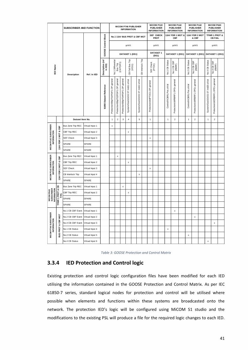
41
Table 3: GOOSE Protection and Control Matrix
3.3.4 IED Protection and Control logic
Existing protection and control logic configuration files have been modified for each IED
utilising the information contained in the GOOSE Protection and Control Matrix. As per IEC
61850-7 series, standard logical nodes for protection and control will be utilised where
possible when elements and functions within these systems are broadcasted onto the
network. The protection IED’s logic will be configured using MiCOM S1 studio and the
modifications to the existing PSL will produce a file for the required logic changes to each IED.
Descri
pti
on
(re
f
in I
ED
)
No.1
CB
Sta
tus
No.1
CB
CB
F
(RB
RF
)
No.2
CB
Sta
tus
No.2
CB
CB
F
(RB
RF
)
No.4
CB
Sta
tus
No.4
CB
CB
F
(RB
RF
)
61850 D
ata
set
Refe
ren
ce
Pro
tection/B
bpT
01P
DIF
1.O
P.g
enera
l
Pro
tection/B
bpT
02P
DIF
1.O
P.g
enera
l
Pro
tection/B
bpT
04P
DIF
1.O
P.g
enera
l
Syste
m/G
osG
GIO
2.S
T.I
nd11.s
tVal
Syste
m/G
osG
GIO
2.S
T.I
nd12.s
tVal
Pro
tection/e
fdP
TO
C1.O
P.g
enera
l
Contr
ol/X
CB
R1.P
os.s
tVal
Pro
tection/c
bfR
BR
F1.O
PE
x.g
enera
l
Contr
ol/X
CB
R1.P
os.s
tVal
Pro
tection/c
bfR
BR
F1.O
PE
x.g
enera
l
Syste
m/G
osG
GIO
2.S
T.I
nd20.s
tVal
Pro
tection/c
bf2
RB
RF
1.O
PE
x.g
enera
l
1 2 3 4 5 1 1 2 1 2 1 2
Bus Zone Trip REC Virtual Input 1 x
CBF Trip REC Virtual Input 2 x
SEF Check Virtual Input 3 x
SPARE SPARE
SPARE SPARE
Bus Zone Trip REC Virtual Input 1 x
CBF Trip REC Virtual Input 2 x
SEF Check Virtual Input 3 x
CB Interlock Trip Virtual Input 4 x
SPARE SPARE
Bus Zone Trip REC Virtual Input 1 x
CBF Trip REC Virtual Input 2 x
SPARE SPARE
SPARE SPARE
No.1 CB CBF Event Virtual Input 1 x
No.2 CB CBF Event Virtual Input 2 x
No.4 CB CBF Event Virtual Input 3 x
No.1 CB Status Virtual Input 4 x
No.2 CB Status Virtual Input 5 x
No.4 CB Status Virtual Input 6 x
MiC
OM
P7
46
SU
BS
CR
IBE
R
INF
OR
MA
TIO
N
BU
S P
RO
T &
CB
F M
GT
Dataset Item No.
MiC
OM
P1
42
SU
BS
CR
IBE
R
INF
OR
MA
TIO
N
11kV
FD
R 1
MG
T &
CB
F
MiC
OM
P1
42
SU
BS
CR
IBE
R
INF
OR
MA
TIO
N
11kV
FD
R 2
MG
T &
CB
F
MiC
OM
P6
43
SU
BS
CR
IBE
R
INF
OR
MA
TIO
N
TF
MR
1 P
RO
T &
CB
FA
IL
CB
Fail
Bus T
rip
(VO
11)
CB
Inte
rlock T
rip
SE
F C
heck
(PT
OC
)
gcb01
DATASET 1 (DS1)DATASET 1
(DS1)DATASET 1 (DS1) DATASET 1 (DS1) DATASET 1 (DS1)
MiCOM P643
PUBLISHER
INFORMATION
Description Ref. In IED
GO
OS
E C
on
tro
l B
lock
No.1 11kV BUS PROT & CBF MGTSEF CHECK
PROT
11kV FDR 1 MGT &
CBF
11kV FDR 2 MGT
& CBF
TFMR 1 PROT &
CB FAIL
gcb01
IED
Nam
e
SUBSCRIBER AND FUNCTIONMiCOM P746 PUBLISHER
INFORMATION
MiCOM P122
PUBLISHER
INFORMATION
MiCOM P142
PUBLISHER
INFORMATION
MiCOM P142
PUBLISHER
INFORMATION
gcb01 gcb01 gcb01
No.1
Diffe
rential
Bus T
rip
(LN
:PD
IF1)
42
This enables the link between the protection IED internal logic and functions and their
association with the receiving and sending GOOSE messages. The IED logic developed and IED’s
internal logic utilised in this design is illustrated in Appendix B
3.3.5 Substation Configuration Language (SCL)
The system design and communication engineering of the simulated substation was performed
using the Schneider Electric SET system configurator tool, which is utilised to configure the
data exchange between IED’s and communication parameters for the substation protection
system. The GOOSE Protection and Control Matrix was used to configure the datasets, logical
nodes and the publishing/subscribing relationship of each IED. A redundant station bus
network was configured with the associated IED’s connected to the network. All of substation
IED’s ICD files were imported into the system configuration tool to their associated IED’s. Once
the ICD files were imported into the system, each IED’s GOOSE control block and dataset’s
were configured with the proposed published logical nodes within each control block. The
network communication and GOOSE control block communication parameters were
configured which included the MAC address, APPID, VLAN ID, VLAN priority and retransmission
times. The next step of the process was to specify the senders (publishers) and the receivers
(subscribers) of each GOOSE message. The GOOSE control blocks MAC address and APP IDs
were auto-assigned to a unique number using the tool. This reduced the need to have a design
rule in place for these parameters and the need to change the parameters manually, which will
reduce the risk of human error during the configuration process and therefore testing of these
parameters. One of the advantages of only using Schneider Electric IED’s within this simulated
network was that the system configuration tool enabled the direct mapping of each GOOSE
message to the IED’s internal virtual input address. If alternative manufacturers IED’s were
used in the system, this engineering task would have to be performed within the
manufacturers IED configurator tool. This manual engineering task could potentially create
additional engineering and design errors during the mapping of the messages to the IED’s
internal addresses. Figure 27 illustrates the logical view of the publishing and subscribing
relationship of the network and the mapping between the IED’s internal virtual input address.
A system configuration description (SCD) file was created after completion of this process. The
next step in the engineering process was to import the SCD file into the Schneider Electric S1
studio IED configuration tool where configured IED description (CID) files were created and
sent to each IED on the network.
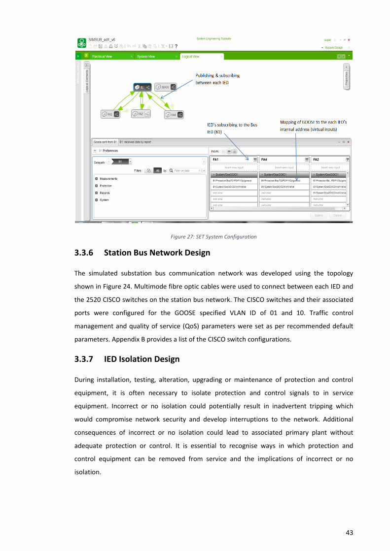
43
Figure 27: SET System Configuration
3.3.6 Station Bus Network Design
The simulated substation bus communication network was developed using the topology
shown in Figure 24. Multimode fibre optic cables were used to connect between each IED and
the 2520 CISCO switches on the station bus network. The CISCO switches and their associated
ports were configured for the GOOSE specified VLAN ID of 01 and 10. Traffic control
management and quality of service (QoS) parameters were set as per recommended default
parameters. Appendix B provides a list of the CISCO switch configurations.
3.3.7 IED Isolation Design
During installation, testing, alteration, upgrading or maintenance of protection and control
equipment, it is often necessary to isolate protection and control signals to in service
equipment. Incorrect or no isolation could potentially result in inadvertent tripping which
would compromise network security and develop interruptions to the network. Additional
consequences of incorrect or no isolation could lead to associated primary plant without
adequate protection or control. It is essential to recognise ways in which protection and
control equipment can be removed from service and the implications of incorrect or no
isolation.
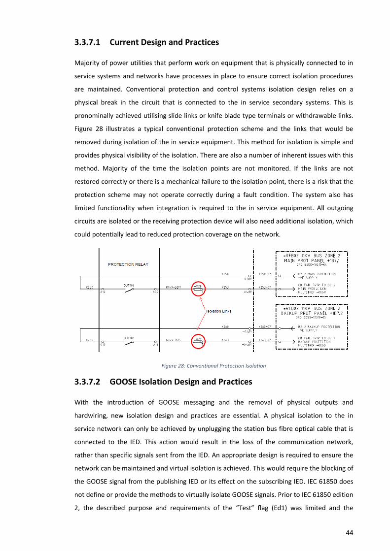
44
3.3.7.1 Current Design and Practices
Majority of power utilities that perform work on equipment that is physically connected to in
service systems and networks have processes in place to ensure correct isolation procedures
are maintained. Conventional protection and control systems isolation design relies on a
physical break in the circuit that is connected to the in service secondary systems. This is
pronominally achieved utilising slide links or knife blade type terminals or withdrawable links.
Figure 28 illustrates a typical conventional protection scheme and the links that would be
removed during isolation of the in service equipment. This method for isolation is simple and
provides physical visibility of the isolation. There are also a number of inherent issues with this
method. Majority of the time the isolation points are not monitored. If the links are not
restored correctly or there is a mechanical failure to the isolation point, there is a risk that the
protection scheme may not operate correctly during a fault condition. The system also has
limited functionality when integration is required to the in service equipment. All outgoing
circuits are isolated or the receiving protection device will also need additional isolation, which
could potentially lead to reduced protection coverage on the network.
Figure 28: Conventional Protection Isolation
3.3.7.2 GOOSE Isolation Design and Practices
With the introduction of GOOSE messaging and the removal of physical outputs and
hardwiring, new isolation design and practices are essential. A physical isolation to the in
service network can only be achieved by unplugging the station bus fibre optical cable that is
connected to the IED. This action would result in the loss of the communication network,
rather than specific signals sent from the IED. An appropriate design is required to ensure the
network can be maintained and virtual isolation is achieved. This would require the blocking of
the GOOSE signal from the publishing IED or its effect on the subscribing IED. IEC 61850 does
not define or provide the methods to virtually isolate GOOSE signals. Prior to IEC 61850 edition
2, the described purpose and requirements of the “Test” flag (Ed1) was limited and the
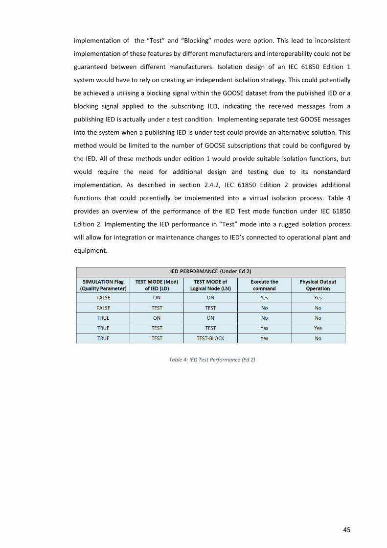
45
implementation of the “Test” and “Blocking” modes were option. This lead to inconsistent
implementation of these features by different manufacturers and interoperability could not be
guaranteed between different manufacturers. Isolation design of an IEC 61850 Edition 1
system would have to rely on creating an independent isolation strategy. This could potentially
be achieved a utilising a blocking signal within the GOOSE dataset from the published IED or a
blocking signal applied to the subscribing IED, indicating the received messages from a
publishing IED is actually under a test condition. Implementing separate test GOOSE messages
into the system when a publishing IED is under test could provide an alternative solution. This
method would be limited to the number of GOOSE subscriptions that could be configured by
the IED. All of these methods under edition 1 would provide suitable isolation functions, but
would require the need for additional design and testing due to its nonstandard
implementation. As described in section 2.4.2, IEC 61850 Edition 2 provides additional
functions that could potentially be implemented into a virtual isolation process. Table 4
provides an overview of the performance of the IED Test mode function under IEC 61850
Edition 2. Implementing the IED performance in “Test” mode into a rugged isolation process
will allow for integration or maintenance changes to IED’s connected to operational plant and
equipment.
Table 4: IED Test Performance (Ed 2)
46
Chapter 4
Risk Assessment Methodology & Test Coverage
4.1 Risk Assessment Methodology
4.1.1 Overview
Only a structured and systematic analysing process will help identify what hardware,
configurations, and functions that require testing prior to commissioning a substation using IEC
61850 Station bus GOOSE messaging. This analysing process will be achieved using a risk
assessment methodology. This will determine if mechanisms are required to validate or verify
the intended design during the testing and commissioning process. The risk assessment
methodology that will be implemented to determine these mechanisms is the Hazard and
Operability Studies (HAZOP) methodology. The two main systems that will be assessed are the
protection IED’s and the station bus network.
4.1.2 HAZOP Methodology
A HAZOP study is a detailed hazard and operability problem identification process. HAZOP
deals with the identification of potential deviations from the design intent, examination of
their possible causes and assessment of their consequences (International Electrotechnical
Commission, 2003). The IEC 61882 standard will be used as the reference standard for this
assessment. Figure 29 illustrates the flow chart of the HAZOP examination procedure.

47
Figure 29: Flow chart of the HAZOP examination procedure (International Electrotechnical Commission, 2003)
The first step of the procedure is to select a part of the overall design, examine, and agree of
that parts design intent. The design intent of that part of the design is explained by the use of
block logic diagrams and the relevant elements, input values and functions associated with
these identified. A guide word is selected to assess if the relevant elements, input values and
functions being studied could potentially have a deviation from the design intent. If a deviation
from the design intent is identified during this step, it is assessed for possible causes and
consequences. CIGRE working group B5.32 (2009) and the IEC 61882 recommend the use of
the HAZOP guide words for Programmable Electronic Systems (PES) and modified guide words
for logical nodes. The working group describes physical components like an IED and switches
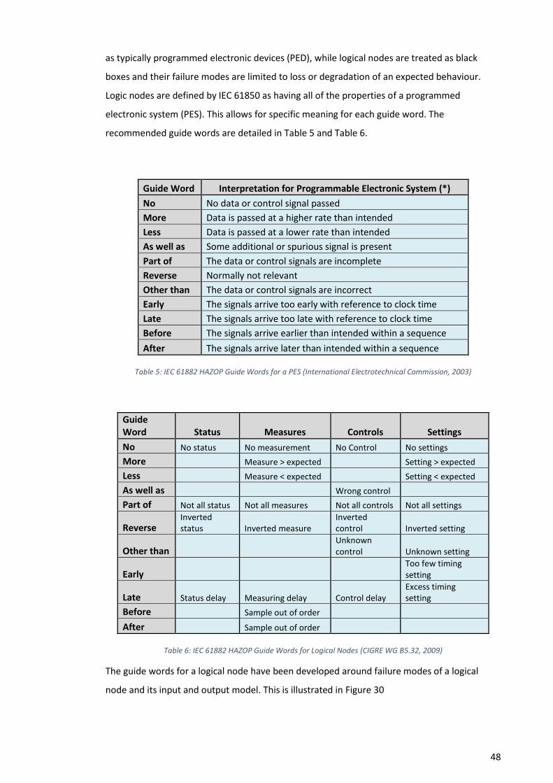
48
as typically programmed electronic devices (PED), while logical nodes are treated as black
boxes and their failure modes are limited to loss or degradation of an expected behaviour.
Logic nodes are defined by IEC 61850 as having all of the properties of a programmed
electronic system (PES). This allows for specific meaning for each guide word. The
recommended guide words are detailed in Table 5 and Table 6.
Guide Word Interpretation for Programmable Electronic System (*)
No No data or control signal passed
More Data is passed at a higher rate than intended
Less Data is passed at a lower rate than intended
As well as Some additional or spurious signal is present
Part of The data or control signals are incomplete
Reverse Normally not relevant
Other than The data or control signals are incorrect
Early The signals arrive too early with reference to clock time
Late The signals arrive too late with reference to clock time
Before The signals arrive earlier than intended within a sequence
After The signals arrive later than intended within a sequence
Table 5: IEC 61882 HAZOP Guide Words for a PES (International Electrotechnical Commission, 2003)
Guide Word Status Measures Controls Settings
No No status No measurement No Control No settings
More Measure > expected Setting > expected
Less Measure < expected Setting < expected
As well as Wrong control
Part of Not all status Not all measures Not all controls Not all settings
Reverse Inverted status Inverted measure
Inverted control Inverted setting
Other than Unknown control Unknown setting
Early Too few timing setting
Late Status delay Measuring delay Control delay Excess timing setting
Before Sample out of order
After Sample out of order
Table 6: IEC 61882 HAZOP Guide Words for Logical Nodes (CIGRE WG B5.32, 2009)
The guide words for a logical node have been developed around failure modes of a logical
node and its input and output model. This is illustrated in Figure 30
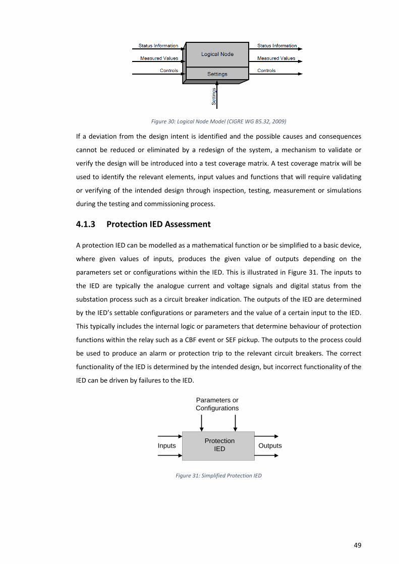
49
Figure 30: Logical Node Model (CIGRE WG B5.32, 2009)
If a deviation from the design intent is identified and the possible causes and consequences
cannot be reduced or eliminated by a redesign of the system, a mechanism to validate or
verify the design will be introduced into a test coverage matrix. A test coverage matrix will be
used to identify the relevant elements, input values and functions that will require validating
or verifying of the intended design through inspection, testing, measurement or simulations
during the testing and commissioning process.
4.1.3 Protection IED Assessment
A protection IED can be modelled as a mathematical function or be simplified to a basic device,
where given values of inputs, produces the given value of outputs depending on the
parameters set or configurations within the IED. This is illustrated in Figure 31. The inputs to
the IED are typically the analogue current and voltage signals and digital status from the
substation process such as a circuit breaker indication. The outputs of the IED are determined
by the IED’s settable configurations or parameters and the value of a certain input to the IED.
This typically includes the internal logic or parameters that determine behaviour of protection
functions within the relay such as a CBF event or SEF pickup. The outputs to the process could
be used to produce an alarm or protection trip to the relevant circuit breakers. The correct
functionality of the IED is determined by the intended design, but incorrect functionality of the
IED can be driven by failures to the IED.
Protection
IEDInputs Outputs
Parameters or
Configurations
Figure 31: Simplified Protection IED
50
4.1.3.1 IED Failure Modes
CIGRE working group B5.32 (2009) describe failure modes of an IED can be broken down to
functional failures and component failures. Functional failures a defined as conditions where
the function or in this case the IED has not performed the expected output. These failures
within a protection scheme could be the protection IED failing to trip a circuit breaker for a
fault or tripping the incorrect circuit breaker. The following conditions can represent a
functional failure of an IED and in turn the system.
Incorrect output signals/messages or destination of signals/messages
Output signals/messages sent to early or to late
No output signals/messages sent or incorrect sequence of output signals/messages
The IED will be broken down to two different component failure modes, physical and logical
node failures. Physical component failures are failures to the IED’s physical hardware and are
normally caused by the environment, such as broken hardware, short circuits or physical wear
and tear or aging on hardware. Where logical node failures are conceptual components such
as software modules and the logic or code within the IED that act as components. The
following conditions can represent a logical node failure of an IED and in turn the system.
Incorrect setting or parameters
Incorrect configuration
Incorrect code, firmware or software bugs
Incorrect or no input/output signals/messages
Input/output/processing signals/messages sent to early or to late
Establishing correct settings, configurations or parameters on an IED is critical for its intended
operation and performance. IEEE/PSCR Working Group I18 identified that errors in IED settings
can arise from many different sources, some technical, some procedural, some administrative
and some inadvertent (IEEE WG I18, 2011).
4.1.4 Station Bus Network Assessment
The station bus network is the backbone of an IEC 61850 substation protection system using
GOOSE messaging. While the protection IED ensures signals are sent and received for a given
protection function. The station bus network is the virtual highway for these signals, ensuring
the signals transmitted from the publishing IED’s are received by the subscribing IED’s. In a
conventional protection system, copper wiring between IED’s performed this function. The
design of the station bus network needs to ensure the network architecture provides EMI
51
immunity, reliability, availability, redundancy and maintainability. With the GOOSE model only
mapped directly to the Link (layer 2) and Physical (layer 1) components, the station bus
network can be broken down to these components to identify potential failures in the design
intent. The physical layer consists of the hardware used as the medium to transfer the data
such as optical fibre or twisted pair copper cabling. While the link layer consist of bridges such
as network switches. Similar to the protection IED a bridge can be simplified to a basic device,
where given values of inputs, produces the given value of outputs depending on the
parameters set or configurations within the device. The most important function of the bridge
is to enforce network management and provide network redundancy. Dolezilek & Dearien
(2015) discuss one of the major challenges of testing a station bus network is ensuring the
network architecture is design to accommodate the required traffic on the network and traffic
control methods are in place to ensure that the time critical protection data is sent and
received in the allowable times. IEC 61850-90-4 section 18 provides guidance on network
testing for IEC 61850 communication networks. The standard recommends that integrator
acceptance and verification tests should be completed to verify which products meet the
functional and performance requirements for the intended network configuration under
worst-case conditions (International Electrotechnical Commission, 2013). This testing is
normally completed on several design standards and products and the results of the testing
are used to decide which is the best design and product for the integrators future design
standards and installations.
4.1.4.1 Network Failure Modes
Similar to the IED the network failure modes are physical component failures to the network
physical hardware and logical node failures to the switches such as software modules and the
logic or code within the device. The following conditions can represent a physical failure to the
network hardware.
Damaged fibre or cable and/or associated connectors
Failure to the switch power supply or electronic circuits
The following conditions can represent a logical node failure of a network bridge and in turn
the system.
Incorrect setting or parameters
Incorrect configuration
Incorrect code, firmware or software bugs
Incorrect or no input/output signals/messages
Input/output/processing signals/messages sent to early or to late

52
4.1.5 IEC 61850 Station Bus GOOSE Messaging HAZOP Assessment
With the intended design identified in section 3.3 and the potential failures and possible
causes of the failures to an IED or network device identified in section 4.1.3 and 4.1.4, a HAZOP
risk assessment can be carried out on a protection scheme and its associated IED’s, network
devices and functions that utilise GOOSE messaging on the station bus network. The HAZOP
flow chart illustrated in Figure 29, the HAZOP examination template in Figure 32 and a
data/control flow diagram for the scheme will be the tools used to assess the scheme and its
intended design. This will drive the required testing requirements and actions during the
testing and commissioning process for this particular scheme.
Figure 32: HAZOP Examination Template
4.1.5.1 Circuit Breaker Fail Protection Scheme
Utilising the data/control flow diagram illustrated in Figure 33 and the design of the circuit
breaker failure scheme, a HAZOP assessment of the circuit breaker fail scheme was developed.
Appendix C provides the full details of the HAZOP examination and assessment.
SHEET:
REFERENCE DRAWING No.: DATE:
TEAM COMPOSITION:
PART CONSIDERED:
DESIGN INTENT:
No. Element Characteristic Guide word Deviation Possible causes Consequences
STUDY TITLE:
Safeguards &/or Test Action
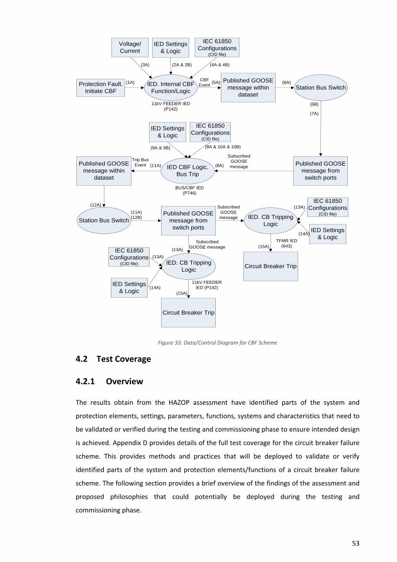
53
IED Settings
& Logic
IED. Internal CBF
Function/Logic
IEC 61850
Configurations (CID file)
Protection Fault.
Initiate CBF
Voltage/
Current
Station Bus Switch
Published GOOSE
message within
dataset
CBF
Event
Published GOOSE
message from
switch ports
11kV FEEDER IED
(P142)
IED CBF Logic.
Bus Trip
BUS/CBF IED
(P746)
Subscribed
GOOSE
messagePublished GOOSE
message within
dataset
Trip Bus
Event
IED. CB Tripping
Logic
TFMR IED
(643)
IED. CB Tripping
Logic
11kV FEEDER
IED (P142)
Subscribed
GOOSE
messageStation Bus Switch
Published GOOSE
message from
switch ports
Subscribed
GOOSE message
(1A)
(2A & 2B)(3A) (4A & 4B)
(5A) (6A)
(6B)
(7A)
(8A)
IED Settings
& Logic
IEC 61850
Configurations (CID file)
(9A & 9B) (8A & 10A & 10B)
Circuit Breaker Trip
(11A)
(12A)
(12B)
(11A)
(13A)
Circuit Breaker Trip
IED Settings
& Logic
IEC 61850
Configurations (CID file)
IED Settings
& Logic
IEC 61850
Configurations (CID file)
(13A)
(14A)
(15A)
(13A)
(14A)
(15A)
Figure 33: Data/Control Diagram for CBF Scheme
4.2 Test Coverage
4.2.1 Overview
The results obtain from the HAZOP assessment have identified parts of the system and
protection elements, settings, parameters, functions, systems and characteristics that need to
be validated or verified during the testing and commissioning phase to ensure intended design
is achieved. Appendix D provides details of the full test coverage for the circuit breaker failure
scheme. This provides methods and practices that will be deployed to validate or verify
identified parts of the system and protection elements/functions of a circuit breaker failure
scheme. The following section provides a brief overview of the findings of the assessment and
proposed philosophies that could potentially be deployed during the testing and
commissioning phase.

54
4.2.2 IED & Protection Scheme Test Coverage
4.2.2.1 Conventional IED & Protection Scheme Test Coverage
With conventional microprocessor based IED’s there are three testing and commissioning
philosophies exist. These are element testing, logic testing and integration testing (IEEE WG
I18, 2011). Throughout the industry there are two theories exist for element testing. The first
is to prove that each programmable element and setting within the IED operates at its settable
value. This practice continues to utilise the methods that are performed on electromechanical
and electronic relays when verifying that electronic or mechanical components operate
correctly at their settable values. The second theory relies on the digital nature of the IED and
that no or reduced element testing is required. The concept behind this theory is that
microprocessor based IEDs have superior self-monitoring or supervision capabilities and
element testing only provides confirmation that the element setting has applied correctly
within the IED. While both theories recommend that verification, be performed on non-
monitored parts of the IED. This may include the current and voltage transformers, A/D
converters and the IED’s inputs and outputs. Figure 34 illustrates the components of a
microprocessor based IED.
Figure 34: Microprocessor IED Typical Components (Power System Relaying Committee, 2009)
Programmable logic enables the IED to be customised to the specific design of the protection
or control system. This is implemented utilising logical gates, timers, protection elements,
opto-inputs and outputs. Logic testing of microprocessor IED’s verifies the programmable logic
set within the IED operates as per its intended design, such as a protection element delivers a
signal within the logic to an output that performs a protection trip to a physical circuit breaker.
While element testing only verifies that the particular element is set correctly within the IED,
logic testing verifies that the logical sequence integrated into the IED are valid and operate the
IED outputs as per the intended design specifications. The integration testing of a protection
55
and control system is the method utilised on site to prove that a piece of plant or equipment is
correctly connected and integrated into the site to form a complete operational system. This
ensures that an output from a particular IED sends a signal to the designated piece of plant or
equipment and the required action is processed and executed. This could potentially be a
signal to a circuit breaker to trip or a signal to another IED to enable a part of the internal logic
or protection function.
4.2.2.2 IEC 61850 IED & Protection Scheme Test Coverage
IEC 61850 substation systems are based on the open exchange of standardised information
between any of the substation IED’s. While this concept takes on a similar nature as software
applications, the IED still takes on the same protection philosophies as a conventional IED.
With respect to an IEC 61850 station bus system, the main difference is that the I/O of the IED
is achieve using digital GOOSE messages over the LAN, instead of utilising a physical inputs or
outputs. An IEC 61850 protection IED still requires settings applied for the protection elements
and programmable logic configured for internal mapping between virtual inputs and outputs.
This conceptual model enables an IEC 61850 station bus IED to be broken into three testing
and commissioning philosophies, similar to conventional IED testing and commissioning. These
are element testing, logic testing and publishing/subscribing testing. However, a system
approach to testing can be taken due to the relationship between the elements, logic and
publishing/subscribing of the IED. These tests can be achieved separately or as an entire
system depending on proposed implementation of the protection system.
Similar to conventional microprocessor IED element testing, both theories can exist for an IEC
61850 IED. If the second theory is applied, that the digital nature of the IED and that no or
reduced element testing is required, it is critical to ensure other processes and control
measures are in place to ensure that the potential to have incorrect settings applied are
significantly reduced. Extensive evaluation and standardisation of IED hardware, firmware and
software utilised to apply the settings can potentially reduce technical issues. Developing
standard configurations for the IED’s and testing the standards prior to releasing the files for
operational or project use can potentially reduce technical issues. While implementing a
rugged quality assurance system, configuration management system and establishing an audit
and validation process can potentially reduce procedural, administrative and inadvertent
issues. These are recommendations from IEEE standard C37.231, IEEE/PSCR working group I18
and C3. Verification of non-monitored parts of the IED such as the current and voltage
transformers, A/D converters are still critical. The extent of element testing on either a
conventional or IEC 61850 IED requires additional engineering justification and assessment.
This is outside the scope of this project. If element testing can be performed in conjunction

56
with other testing to optimise and reduce the number of test required, this should be included
during the testing and commissioning process. This will ensure the protection system is not
solely relying on the digital nature of the device to protect and reliably operate the required
equipment.
With this consideration, all future testing coverage will investigate and implement additional
coverage if possible to cover element testing of the IED. One of the major differences between
a conventional and IEC 61850 IED is the signal sent from an IED to other parts of the secondary
systems. While conventional IED’s utilise configurable logic and internal mapping to physical
outputs to perform this task, station bus IED’s utilise a GOOSE message to be published onto
the network via the assigned logical nodes (LN) within the dataset. This function is closely
compared to logic testing of a conventional IED, where test are performed to ensure that the
configurable logic and protection elements drives the correct output. Adapting this testing
practice to an IEC 61850 station bus protection will enable the confirmation that the correct
logical nodes (LN) utilised within the dataset has been assigned and is published onto the
network. Including element testing into this test can provide additional test coverage. An
example of this is to measure the operation and accuracy of the circuit breaker failure time
during this testing. While this is not elements testing, the element that are deployed within the
GOOSE message can potentially be verified for their correct settable value determined by the
protection study. In most cases, power system simulation of the protection element would be
performed. This would confirm the operation and accuracy of the protection IED and the IED
associated protection element would be measured. While this is a very similar approach to
testing conventional protection relays, one of the major differences is the sensing of the
operation of the element. The measurement of the element operation would be performed on
the station network for the GOOSE message, not a physical contact within the protection relay.
If the SCL files for the IED under test are utilised within the testing, the GOOSE control block
and dataset items number can be verified during the same test. Majority of IEC 61850
complaint test sets import the SCL files for simulation of the GOOSE messages that could
potentially be published or subscribed by the IED. This would confirm that the configuration
that drives the protection function logical node has been configured within the IED correctly
and the logical node has been assigned within the dataset.
With the above testing confirming, the IED is publishing the correct GOOSE message and some
type of element testing, verification of that message to the subscribing IEDs is critical. The
system configuration tool can simply add IEDs as subscribers, but ensuring the IED is
subscribing to the correct GOOSE message needs to be verified. The system configuration
engineering process assigns items within each publishing dataset manually to the virtual inputs
57
of the subscribing IEDs. This task could also potentially create a mismatch with the virtual input
mapping within the system configuration tool and the mapping of the virtual inputs within the
IED’s internal address mapping or settable protection logic. Testing of the IED’s settable logic
associated with the GOOSE virtual input mapping can be performed on the individual IED
similar to the publishing/element testing. While this testing will verify that the correct
mapping of the GOOSE virtual inputs to the IED and IED associated logic, this testing does not
verify the entire system. Verification that the IED’s and plant is correctly configured, connected
and integrated into the site to form a complete operational system is required. With this
consideration and to optimise testing, testing of the IED’s settable logic associated with the
GOOSE virtual input mapping and publishing/subscribing configuration of the system can be
performed together because of their link between multiple IEDs within the IEC 61850 network.
This testing takes on the same philosophies as integration testing. This ensures that a GOOSE
output from a particular IED is published onto the network and the subscribing IED receives
the message and the required action is processed and executed. While the system
configuration tool enables checking to ensure that the maximum GOOSE messages are not
exceed on the station bus network. This allows measurement of the full protection scheme
and the effect the network latency has on the time critical protection GOOSE message under
potentially normal circumstances. This also provides confirmation that the station switches are
configured correctly for their traffic control management and quality of service (QoS)
parameters for that particular system.
4.2.3 Network Test Coverage
Fibre optical cables play an import role as the links between the IEDs and network switches.
Most physical failures to the fibre optic cable occur during the installation of the cable. The
Telecommunication Industry Association (TIA) of America describe the importance of ensuring
fibre optic cables are installed correctly. Their Failure Mode and Effects Analysis (FMEA) on
networks identified connector contamination and damage to fibre optic cables is the leading
root cause of fibre optic networks failures. Although physical failures to the fibre optic cable
present themselves as either operational or not operational during the testing and
commissioning stage, it is important to reduce the potential of failure after the commissioning
phase. AS/NZS ISO/IEC 14763.3:2012 Telecommunications installations—Implementation and
operation of customer premises cabling Part 3: Testing of optical fibre cabling provides a
guideline for inspection and test schedules. Utilising the guidelines presented in 14763.3:2012,
performing a microscopic visual inspection of all end connectors, confirming continuity &
polarity of cores from end to end provided confirmation that the fibre optical systems has not
been damaged during construction activities. Conducting end-to-end level check (Light &
58
Source) of each multimode fibre would also eliminate the risk of future issues that maybe
encountered during or after the commissioning phase.
As described in IEC 61850-90-4 section 18, switches configurations that affect the GOOSE
messaging need to be verified, these may include IP addresses, port settings, multicast and
VLAN filtering and clock settings. This can be achieved using remote access over SNMP or IEC
61850 objects. IP connectivity between devices on the station bus network can be performed
using an ICMP messaging tool such as Ruggedping. Running this test for an increased interval
will enable the monitoring of any loss data packets during the testing. Removal of fibre optic
cables and switches from the network should be completed to test redundancy and network
resiliency. This testing will confirm that the GOOSE traffic will continue to flow and failures to
the network are reported and messages are received within the required times. While its
critical to ensure network switches have been design to cover the systems traffic control
management and quality of service (QoS) requirement, IEC 61850-90-4 recommend that these
parameters a verified during type testing of systems not during the onsite testing and
commissioning.
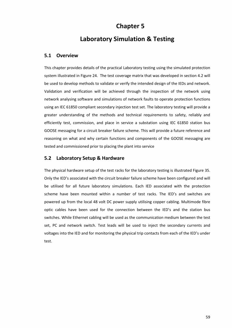
59
Chapter 5
Laboratory Simulation & Testing
5.1 Overview
This chapter provides details of the practical Laboratory testing using the simulated protection
system illustrated in Figure 24. The test coverage matrix that was developed in section 4.2 will
be used to develop methods to validate or verify the intended design of the IEDs and network.
Validation and verification will be achieved through the inspection of the network using
network analysing software and simulations of network faults to operate protection functions
using an IEC 61850 compliant secondary injection test set. The laboratory testing will provide a
greater understanding of the methods and technical requirements to safety, reliably and
efficiently test, commission, and place in service a substation using IEC 61850 station bus
GOOSE messaging for a circuit breaker failure scheme. This will provide a future reference and
reasoning on what and why certain functions and components of the GOOSE messaging are
tested and commissioned prior to placing the plant into service
5.2 Laboratory Setup & Hardware
The physical hardware setup of the test racks for the laboratory testing is illustrated Figure 35.
Only the IED’s associated with the circuit breaker failure scheme have been configured and will
be utilised for all future laboratory simulations. Each IED associated with the protection
scheme have been mounted within a number of test racks. The IED’s and switches are
powered up from the local 48 volt DC power supply utilising copper cabling. Multimode fibre
optic cables have been used for the connection between the IED’s and the station bus
switches. While Ethernet cabling will be used as the communication medium between the test
set, PC and network switch. Test leads will be used to inject the secondary currents and
voltages into the IED and for monitoring the physical trip contacts from each of the IED’s under
test.
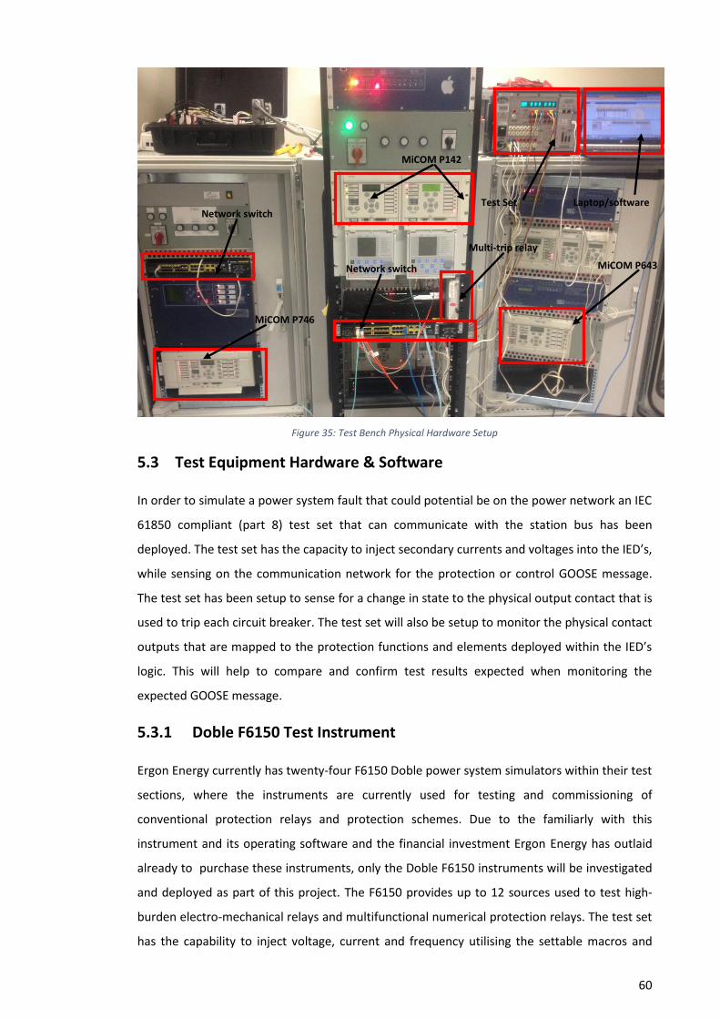
60
Figure 35: Test Bench Physical Hardware Setup
5.3 Test Equipment Hardware & Software
In order to simulate a power system fault that could potential be on the power network an IEC
61850 compliant (part 8) test set that can communicate with the station bus has been
deployed. The test set has the capacity to inject secondary currents and voltages into the IED’s,
while sensing on the communication network for the protection or control GOOSE message.
The test set has been setup to sense for a change in state to the physical output contact that is
used to trip each circuit breaker. The test set will also be setup to monitor the physical contact
outputs that are mapped to the protection functions and elements deployed within the IED’s
logic. This will help to compare and confirm test results expected when monitoring the
expected GOOSE message.
5.3.1 Doble F6150 Test Instrument
Ergon Energy currently has twenty-four F6150 Doble power system simulators within their test
sections, where the instruments are currently used for testing and commissioning of
conventional protection relays and protection schemes. Due to the familiarly with this
instrument and its operating software and the financial investment Ergon Energy has outlaid
already to purchase these instruments, only the Doble F6150 instruments will be investigated
and deployed as part of this project. The F6150 provides up to 12 sources used to test high-
burden electro-mechanical relays and multifunctional numerical protection relays. The test set
has the capability to inject voltage, current and frequency utilising the settable macros and
MiCOM P643
Test Set Laptop/software
Network switch
MiCOM P746
MiCOM P142
Network switch
Multi-trip relay
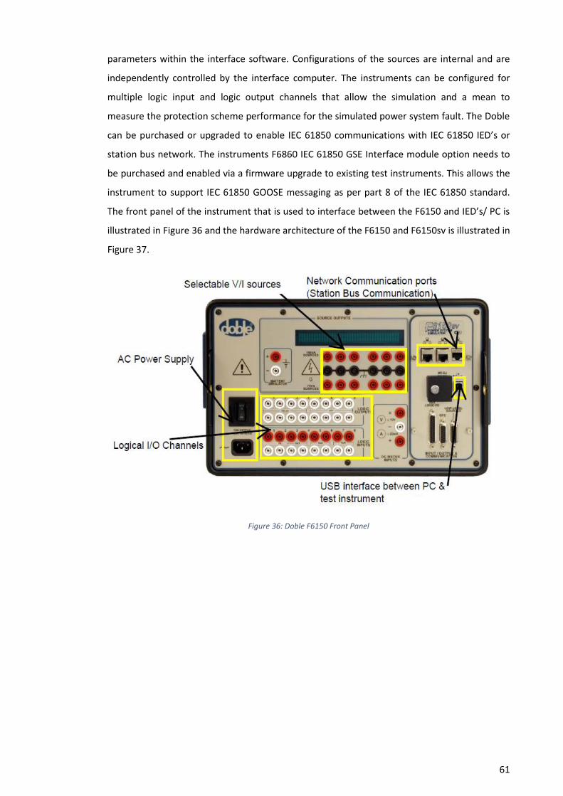
61
parameters within the interface software. Configurations of the sources are internal and are
independently controlled by the interface computer. The instruments can be configured for
multiple logic input and logic output channels that allow the simulation and a mean to
measure the protection scheme performance for the simulated power system fault. The Doble
can be purchased or upgraded to enable IEC 61850 communications with IEC 61850 IED’s or
station bus network. The instruments F6860 IEC 61850 GSE Interface module option needs to
be purchased and enabled via a firmware upgrade to existing test instruments. This allows the
instrument to support IEC 61850 GOOSE messaging as per part 8 of the IEC 61850 standard.
The front panel of the instrument that is used to interface between the F6150 and IED’s/ PC is
illustrated in Figure 36 and the hardware architecture of the F6150 and F6150sv is illustrated in
Figure 37.
Figure 36: Doble F6150 Front Panel
62
Figure 37: Doble Hardware Architecture
5.3.2 Doble Protection Suite & GSE Configurator Tool
Protection Suite is the software application used in conjunction with the Doble F6150 test
instrument. Protection suite enables the operator to setup the automated power system
simulations to the IED’s and protection schemes. The automated test plans have a number of
pre-defined test types and simulation macro’s that allow the user to confirm the operation and
accuracy of the IED and IED functions as well as the performance of the complete protection
scheme. The Doble F6150 test instrument needs to be configured to the correct network
parameters and GOOSE messaging parameters as per the site SCL files. To enable these
changes, Doble’s IEC 61850 GSE configurator software is required to configure the F6150
power system simulator. This allows testing of the protection schemes and IED’s that use the
IEC 61850 standard for sending and receiving of GOOSE messages over the Ethernet substation
LAN. The GSE configurator tool utilises the IEC 61850 SCL to interface and configure the
protection suite software, which enables the use of GOOSE messaging within the required test
simulations. The project or site SCL files (ICD, SCD, CID) are imported into the GSE configurator,
which results in a detailed listing of the messages and the dataset items within the imported
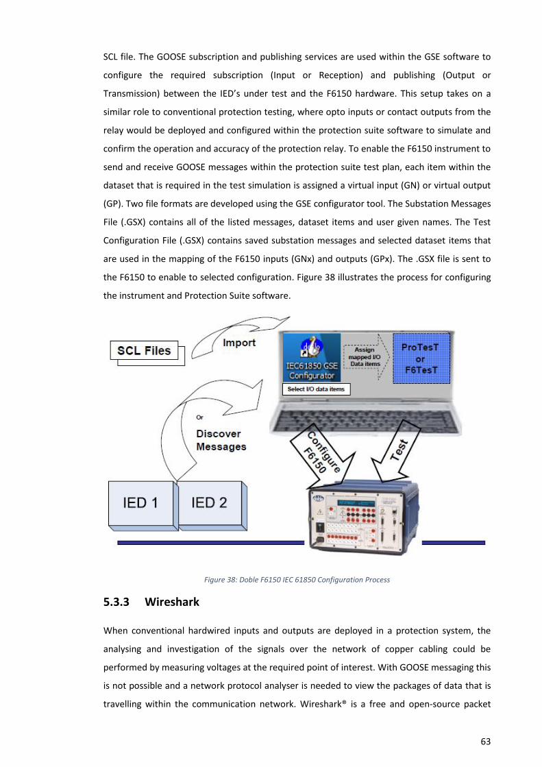
63
SCL file. The GOOSE subscription and publishing services are used within the GSE software to
configure the required subscription (Input or Reception) and publishing (Output or
Transmission) between the IED’s under test and the F6150 hardware. This setup takes on a
similar role to conventional protection testing, where opto inputs or contact outputs from the
relay would be deployed and configured within the protection suite software to simulate and
confirm the operation and accuracy of the protection relay. To enable the F6150 instrument to
send and receive GOOSE messages within the protection suite test plan, each item within the
dataset that is required in the test simulation is assigned a virtual input (GN) or virtual output
(GP). Two file formats are developed using the GSE configurator tool. The Substation Messages
File (.GSX) contains all of the listed messages, dataset items and user given names. The Test
Configuration File (.GSX) contains saved substation messages and selected dataset items that
are used in the mapping of the F6150 inputs (GNx) and outputs (GPx). The .GSX file is sent to
the F6150 to enable to selected configuration. Figure 38 illustrates the process for configuring
the instrument and Protection Suite software.
Figure 38: Doble F6150 IEC 61850 Configuration Process
5.3.3 Wireshark
When conventional hardwired inputs and outputs are deployed in a protection system, the
analysing and investigation of the signals over the network of copper cabling could be
performed by measuring voltages at the required point of interest. With GOOSE messaging this
is not possible and a network protocol analyser is needed to view the packages of data that is
travelling within the communication network. Wireshark® is a free and open-source packet
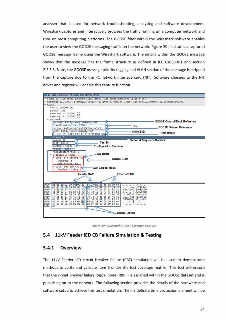
64
analyser that is used for network troubleshooting, analysing and software development.
Wireshark captures and interactively browses the traffic running on a computer network and
runs on most computing platforms. The GOOSE filter within the Wireshark software enables
the user to view the GOOSE messaging traffic on the network. Figure 39 illustrates a captured
GOOSE message frame using the Wireshark software. The details within the GOOSE message
shows that the message has the frame structure as defined in IEC 61850-8-1 and section
2.2.3.3. Note, the GOOSE message priority tagging and VLAN section of the message is stripped
from the capture due to the PC network interface card (NIT). Software changes to the NIT
driver and register will enable this capture function.
Figure 39: Wireshark GOOSE Message Capture
5.4 11kV Feeder IED CB Failure Simulation & Testing
5.4.1 Overview
The 11kV Feeder IED circuit breaker failure (CBF) simulation will be used to demonstrate
methods to verify and validate item 6 under the test coverage matrix. This test will ensure
that the circuit breaker failure logical node (RBRF) is assigned within the GOOSE dataset and is
publishing on to the network. The following section provides the details of the hardware and
software setup to achieve this test simulation. The I>2 definite time protection element will be
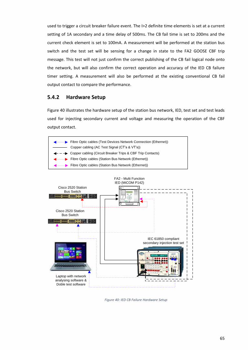
65
used to trigger a circuit breaker failure event. The I>2 definite time elements is set at a current
setting of 1A secondary and a time delay of 500ms. The CB fail time is set to 200ms and the
current check element is set to 100mA. A measurement will be performed at the station bus
switch and the test set will be sensing for a change in state to the FA2 GOOSE CBF trip
message. This test will not just confirm the correct publishing of the CB fail logical node onto
the network, but will also confirm the correct operation and accuracy of the IED CB failure
timer setting. A measurement will also be performed at the existing conventional CB fail
output contact to compare the performance.
5.4.2 Hardware Setup
Figure 40 illustrates the hardware setup of the station bus network, IED, test set and test leads
used for injecting secondary current and voltage and measuring the operation of the CBF
output contact.
Copper cabling (AC Test Signal (CT’s & VT’s))
Copper cabling (Circuit Breaker Trips & CBF Trip Contacts)
Fibre Optic cables (Station Bus Network (Ethernet))
Fibre Optic cables (Station Bus Network (Ethernet))
FA2 - Multi Function
IED (MiCOM P142)
IEC 61850 compliant
secondary injection test set
Laptop with network
analysing software &
Doble test software
Fibre Optic cables (Test Devices Network Connection (Ethernet))
Cisco 2520 Station
Bus Switch
Cisco 2520 Station
Bus Switch
Figure 40: IED CB Failure Hardware Setup

66
5.4.3 Software Setup
5.4.3.1 GSE Configurator
The GSE configurator software has been configured to allow the sending and receiving of the
GOOSE messages over the substation LAN from the FA2 IED. The project SCL file (SCD) has
been imported into the GSE configurator, which results in a detailed listing of the messages
and the dataset items within the imported SCL file. The GOOSE subscription and publishing
services are used within the GSE software to configure the required subscription (Input or
Reception) and publishing (Output or Transmission) between the IED’s under test and the
F6150 hardware. This software setup is illustrated in Figure 41.
Figure 41: GSE Configurator Setup
To enable the F6150 instrument to send and receive GOOSE messages within the protection
suite test plan, each item within the dataset that is required in the test simulation is assigned a
virtual input (GN). The .GSX file that contains the listed messages, dataset items and user given
names is sent to the F6150 to enable to selected configuration. Figure 42 illustrates the
process for configuring virtual inputs (GOOSE messages) for the Doble.

67
Figure 42: GSE Configurator Virtual input setup
A Protection Suite test plan was configured for the testing of the GOOSE CB fail simulation.
This is illustrated in Figure 43. The test plan was setup for a pre-fault condition; this simulation
acts as a normal operating state on the network. There is no fault present during this state that
could potentially trigger a CB fail event. After the prefault condition (500ms), a definite time
fault (I>2) was injected by the test set and the definite time pickup would be reached. This
event would trigger the circuit breaker failure logic illustrated in Figure 18. The CB fail timer is
initiated and starts timing down from its settable value (200ms). If the protection function and
current check elements are still high after the CBF timer expires, a CBF trip will be initiated via
the CBF output contact and a change in state to the GOOSE message CBF bit.
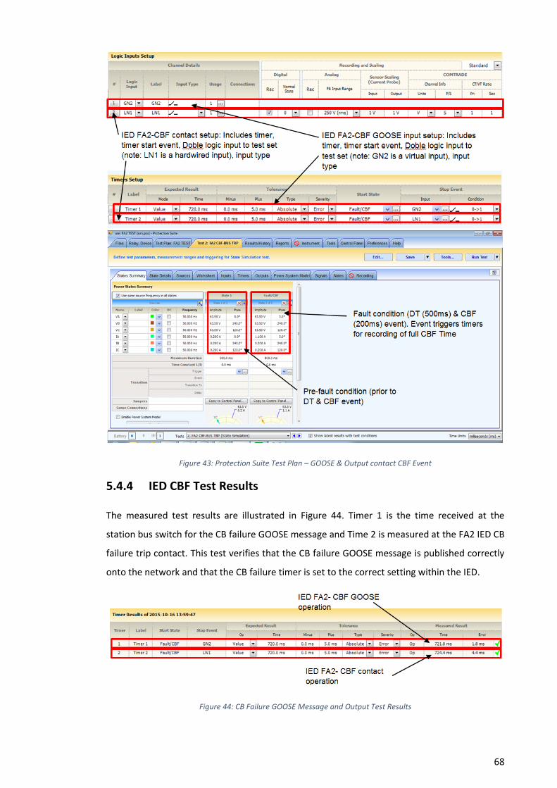
68
Figure 43: Protection Suite Test Plan – GOOSE & Output contact CBF Event
5.4.4 IED CBF Test Results
The measured test results are illustrated in Figure 44. Timer 1 is the time received at the
station bus switch for the CB failure GOOSE message and Time 2 is measured at the FA2 IED CB
failure trip contact. This test verifies that the CB failure GOOSE message is published correctly
onto the network and that the CB failure timer is set to the correct setting within the IED.
Figure 44: CB Failure GOOSE Message and Output Test Results
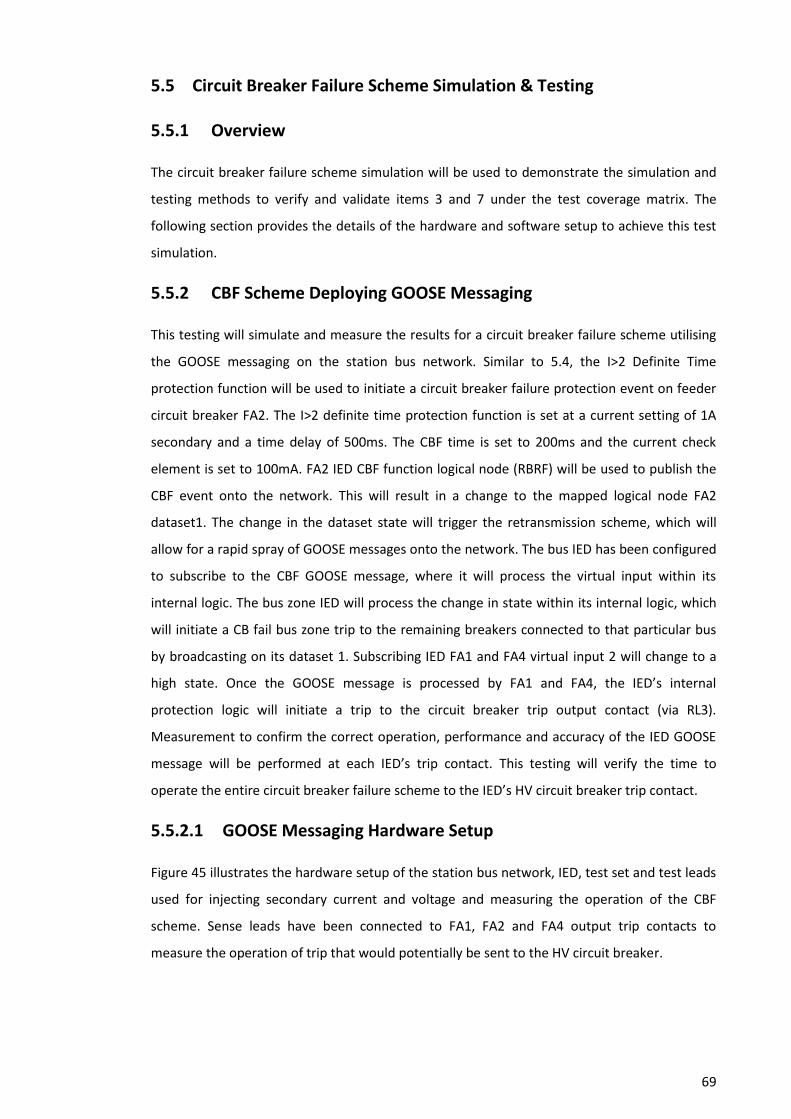
69
5.5 Circuit Breaker Failure Scheme Simulation & Testing
5.5.1 Overview
The circuit breaker failure scheme simulation will be used to demonstrate the simulation and
testing methods to verify and validate items 3 and 7 under the test coverage matrix. The
following section provides the details of the hardware and software setup to achieve this test
simulation.
5.5.2 CBF Scheme Deploying GOOSE Messaging
This testing will simulate and measure the results for a circuit breaker failure scheme utilising
the GOOSE messaging on the station bus network. Similar to 5.4, the I>2 Definite Time
protection function will be used to initiate a circuit breaker failure protection event on feeder
circuit breaker FA2. The I>2 definite time protection function is set at a current setting of 1A
secondary and a time delay of 500ms. The CBF time is set to 200ms and the current check
element is set to 100mA. FA2 IED CBF function logical node (RBRF) will be used to publish the
CBF event onto the network. This will result in a change to the mapped logical node FA2
dataset1. The change in the dataset state will trigger the retransmission scheme, which will
allow for a rapid spray of GOOSE messages onto the network. The bus IED has been configured
to subscribe to the CBF GOOSE message, where it will process the virtual input within its
internal logic. The bus zone IED will process the change in state within its internal logic, which
will initiate a CB fail bus zone trip to the remaining breakers connected to that particular bus
by broadcasting on its dataset 1. Subscribing IED FA1 and FA4 virtual input 2 will change to a
high state. Once the GOOSE message is processed by FA1 and FA4, the IED’s internal
protection logic will initiate a trip to the circuit breaker trip output contact (via RL3).
Measurement to confirm the correct operation, performance and accuracy of the IED GOOSE
message will be performed at each IED’s trip contact. This testing will verify the time to
operate the entire circuit breaker failure scheme to the IED’s HV circuit breaker trip contact.
5.5.2.1 GOOSE Messaging Hardware Setup
Figure 45 illustrates the hardware setup of the station bus network, IED, test set and test leads
used for injecting secondary current and voltage and measuring the operation of the CBF
scheme. Sense leads have been connected to FA1, FA2 and FA4 output trip contacts to
measure the operation of trip that would potentially be sent to the HV circuit breaker.

70
Copper cabling (AC Test Signal (CT’s & VT’s))
FA4 - Transformer
Protection IED
(MiCOM P643)
Copper cabling (Circuit Breaker Trips & 52a Contact to Sim Box)
Fibre Optic cables (Station Bus Network (Ethernet))
Fibre Optic cables (Station Bus Network (Ethernet))
FA2 - Multi Function
IED (MiCOM P142)FA1 - Multi Function
IED (MiCOM P142)
IEC 61850 Secondary
Injection Test Set
Laptop with network
analysing software &
Doble test software
Fibre Optic cables (Test Devices Network Connection (Ethernet))
Low Impedance Bus
Zone Protection IED
(MiCOM P746)
Cisco 2520 Station
Bus Switch
Cisco 2520 Station
Bus Switch
Figure 45: Hardware Setup for CBF Scheme-GOOSE Messaging
5.5.2.2 GOOSE Messaging Software Setup
A Protection Suite test plan was configured for the testing of the GOOSE messaging scheme.
This is illustrated in Figure 46. The test plan was setup for a pre-fault condition; this simulation
acts as a normal operating state on the network. There is no fault present during this state that
could potentially trigger a CB fail event. After the prefault condition (500ms), a definite time
fault (I>2) was injected by the test set and the definite time pickup would be reached. This
event would trigger the circuit breaker failure logic illustrated in Figure 18. The CB fail timer is
initiated and starts timing down from its settable value (200ms). If the protection function and
current check elements are still high after the CBF timer expires, a CBF trip will be initiated via
the GOOSE message CBF bit.
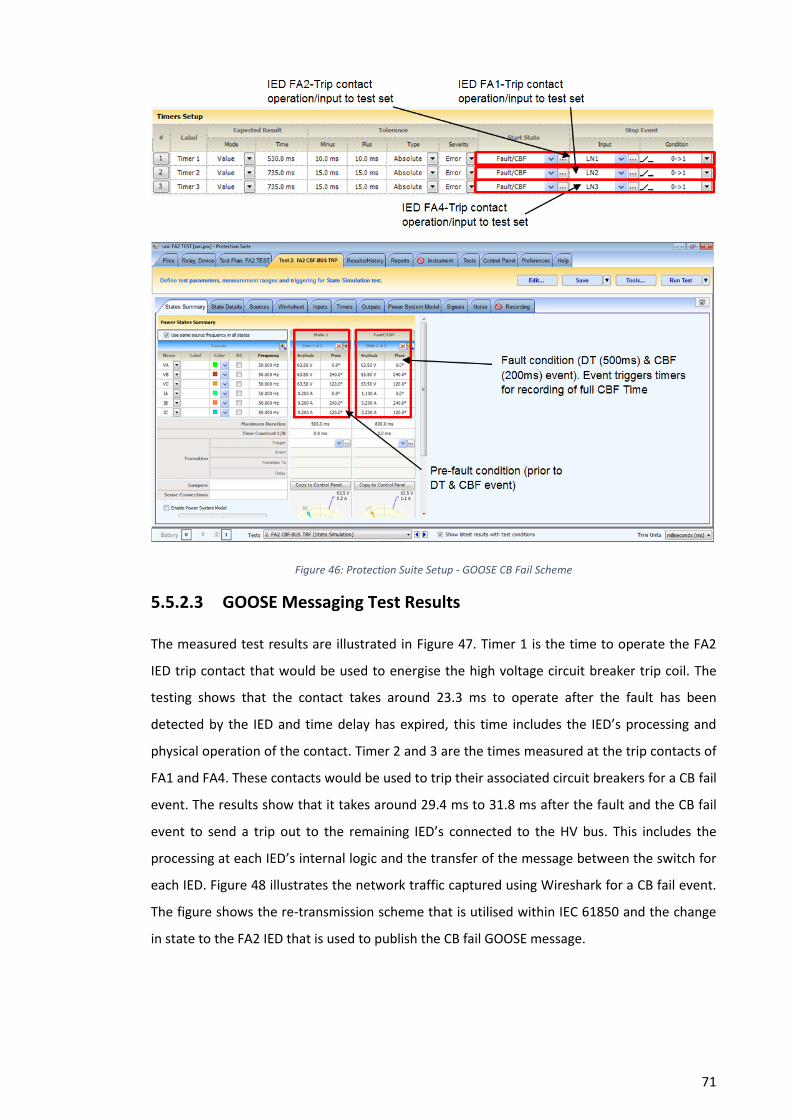
71
Figure 46: Protection Suite Setup - GOOSE CB Fail Scheme
5.5.2.3 GOOSE Messaging Test Results
The measured test results are illustrated in Figure 47. Timer 1 is the time to operate the FA2
IED trip contact that would be used to energise the high voltage circuit breaker trip coil. The
testing shows that the contact takes around 23.3 ms to operate after the fault has been
detected by the IED and time delay has expired, this time includes the IED’s processing and
physical operation of the contact. Timer 2 and 3 are the times measured at the trip contacts of
FA1 and FA4. These contacts would be used to trip their associated circuit breakers for a CB fail
event. The results show that it takes around 29.4 ms to 31.8 ms after the fault and the CB fail
event to send a trip out to the remaining IED’s connected to the HV bus. This includes the
processing at each IED’s internal logic and the transfer of the message between the switch for
each IED. Figure 48 illustrates the network traffic captured using Wireshark for a CB fail event.
The figure shows the re-transmission scheme that is utilised within IEC 61850 and the change
in state to the FA2 IED that is used to publish the CB fail GOOSE message.

72
Figure 47: CB Failure Scheme GOOSE Messaging Test Results
Figure 48: CBF Event Network Traffic Capture

73
Chapter 6
Conclusion
6.1 Overview
The development of the IEC 61850 station bus technology and introducing this technology into
the substation environment has created significant change to current conventional protection
and control systems. Implementing a station bus system generates a substantial change to
existing design and construction practices. The specific project objectives have been met and
will be discussed in this section.
Analysing current protection functions and design standards established a connection between
conventional practices and future practices using GOOSE messaging at a station bus level. The
circuit breaker fail protection scheme, bus zone protection, sensitive earth fault check and
circuit breaker interlocking are potential protection schemes and functions that can utilise the
IEC 61850 station bus. While majority of protection philosophies and the need for the
protection scheme remain the same, the manner in which the system operates, executes and
processes the protection scheme has changed. The introduction of the station bus technology
has removed the need to have copper wiring between IED’s for the sending and receiving of
protection and control signals. The introduction of Ethernet based Local Area Networks (LAN)
to send and receive protection and control signals has greatly reduced the circuitry
requirements of a substation, but has greatly increased the configuration engineering process.
With this change, new engineering processes and standards, new engineering tools, and the
skills to perform the engineering have been introduced. Despite the fact that the IEC 61850
engineering process and the use of the substation configuration language are part of the IEC
61850 standard, there are still a number of capability concerns and inconsistencies when
different manufacturers are introduced into the design process. The need to perform
additional engineering steps with proprietary IED configuration tools introduces additional
design errors and therefore additional testing.
The development of IEC 61850 Edition 2 has corrected technical issues, improved
inconsistencies and clarified interoperability issues encountered from different IED
manufacturers under Edition 1. IEC 61850 Edition 2 “Function Test” and “Simulation” modes
have provided greater functionality that could potentially be utilised during the testing and
commissioning of an IEC 61850 substation. All of the isolation methods under edition 1 would
provide suitable isolation functions, but would require the need for additional design and
testing due to its nonstandard implementation. The “Function Test” mode has the capability to

74
be integrated into a virtual isolation process, which would be used as an isolation mechanism
for in service protection isolation. This edition 2 method for isolation would need limited
testing to verify its intended design because of the conformance testing of this function are
performed under part 10 of the standard.
The Hazard and Operability study (HAZOP) has been identified as an effective, structured and
systematic analysing process. The HAZOP study identified potential deviations from the IEC
61850 station bus circuit breaker failure protection scheme design intent. The HAZOP
identified potential causes (failures or faults) and consequences of that deviation. The highest
potential deviations have been identified as logical node failures. These are conceptual
components such as software modules, logic, settings or parameters and code within the IED.
This is due to the software base nature of IEC 61850. IED physical hardware deviations are
limited due to the IEDs having superior self-monitoring or supervision capabilities. Fibre optic
cables used to connect the station bus are the main physical hardware deviation on the
network. While most deviations occur after the commissioning, it is vital to have inspection
and test schedules to reduce the potential of failure during the operation life of the network.
Extensive evaluation and standardisation of IED and network hardware, firmware and software
utilised to apply the settings can potentially reduce these technical deviations. While
implementing a rugged quality assurance system, configuration management system and
establishing an audit and validation process can potentially reduce procedural, administrative
and inadvertent issues.
Deviations from the design intent identified from the HAZOP assessment were reassessed if
the possible causes and consequences could be reduced or eliminated by a redesign of the
system. If the possible causes and consequences could not be reduced or eliminated by a
redesign of the system, a mechanism to validate or verify the design was introduced into a test
coverage matrix. A test coverage matrix identified the relevant elements, settings, parameters,
functions, systems and characteristics that will require validating or verifying through
inspection, testing, measurement or simulations during the testing and commissioning
process.
The testing and commissioning philosophies that exist for conventional microprocessor based
IED’s and their protection scheme have a similar concept to IEC 61850 IED’s and their
associated protection scheme. However, a system approach to testing can be deployed on an
IEC 61850 system due to the relationship between the elements, logic and
publishing/subscribing of the IED. Verification of non-monitored parts of the IED such as the
current and voltage transformers, A/D converters are still critical, similar to a conventional
microprocessor based IED’s. The introduction of reduced or no element testing on an IEC
75
61850 IED because of its digital nature require additional engineering justification and
assessment. To reduce and optimise the number of test required, element testing can be
performed in conjunction with publishing verification of the IEC 61850 IED. Testing and
confirming that the correct logical nodes (LN) utilised within the dataset has been assigned and
is published onto the network is essential, including element testing into this test can provide
additional test coverage. Verification that the subscribing IED receives the message and the
required action is processed and executed is vital. This testing can achieved separately or as an
entire system depending on proposed implementation of the protection system. Testing of the
network and fibre optic system should be performed with reference to AS/NZS ISO/IEC
14763.3:2012 and in IEC 61850-90-4 section 18.
New testing and commissioning tools are required to perform the required verification and
validation of the protection system, this also drives the need for new and improved skill sets of
the personnel performing these tasks. The development of the simulated substation helped to
evaluate the new engineering processes and standards and new engineering tools. The
laboratory testing utilising the developed simulated substation provided a greater
understanding of the methods, tools and technical requirements to perform these tasks
identified under the test coverage matrix.
The introduction of the Station Bus technology has a significant change in the way a substation
protection system is tested and commissioned with substantial changes to current
philosophies and practices.
6.2 Further Work
Investigate and analyse utilising a HAZOP study all protection functions that can be deployed in
an IEC 61850 station bus system. This will identify the full testing and commissioning
requirements for a station bus system. Testing and commissioning quality assurance
documentation can be developed after a full assessment has been achieved and will enable
development of the assessment criteria.
Investigate and assess the testing and commissioning requirements if process bus technology,
such as merging unit and smart IED’s are implemented into the system.
Develop a Mode and Effects Analysis (FMEA) risk assessment to identify potential preventive
maintenance requirements on an IEC 61850 station bus system. This assessment will allow
utilities to develop maintenance strategies and procedures for an IEC 61850 station bus
system.
76
References
AEMO, 2015. Australian Energy Market Operator National Electricity Rules. [Online]
Available at: http://www.aemo.com.au/About-the-Industry/Legislation/National-Electricity-
Rules
[Accessed 12th April 2015].
Aguilar, R. & Ariza, J., 2010. Integration and Testing Challenges of IEC 61850 Multivendor
Protection Schemes. Manchester, IET, pp. 1-5.
Alexander, A., 2010. IEC 61850 9-2 Process Bus Applications and Benefits. 10th IET
International Conference on Developments in Power System Protection (DPSP 2010). Managing
the Change, pp. 78-78.
Alstom Grid, 2011. Network Protection & Automation Guide. [Online]
Available at: http://www.alstom.com/grid/products-and-services/Substation-automation-
system/protection-relays/Network-Protection-Automation-Guide-NEW-2011-Edition/
[Accessed 28th March 2015].
Alstom Grid, 2015. Testing Protection and Automation through IEC 61850 Edition 2. Sydney,
CIGRE Australia.
Apostolov, A., 2008. Impact of IEC 61850 on the Protection Grading and Testing Process.
Glasgow, IET, pp. 20-25.
Apostolov, A., 2009. Testing of Distributed IEC 61850 Based Protection. Hong Kong, IET.
Apostolov, A., 2010. IEC 61850 Substation Configuration Language and Its Impact on the
Engineering of Distribution Substation Systems. Argentina, IEEE.
Apostolov, A., 2015. Isolation of IED's for Testing in IEC 61850 Based Substion Protection
Systems. Sydney, IEEE.
Apostolov, A. & Vandiver, B., 2007. Functional Testing of IEC 61850 Based Protection Relays.
Texas, IEEE, pp. 333-340.
Australian Standard - AS 2067, 2008. Substations and High Voltage Installations Exceeding 1kV
A.C.. [Online]
Available at: http://www.saiglobal.com/online/autologin.asp
[Accessed 5th July 2015].
Brand, Wimmer, 2014. Reliable Networking. ABB - The Corporate Technical Journal - IEC 61850,
pp. 53 - 56.

77
CIGRE WG B5.32, 2009. Functional Testing of IEC 61850 Based Systems. [Online]
Available at: http://www.cigre.org/Diaporama/CIGRE-Working-Groups-Update
[Accessed 2nd April 2015].
Coggan, Robert;, 2014. Substation Standard Standard for Substation Protection. [Online]
Available at: http://enet/Docs/Standards/STNPublished/STNW1002.pdf
[Accessed 4th May 2015].
Dolezilek, D. & Dearien, j., 2015. Lessons Learned Through Commissioning and Analyzing Data
From Ethernet Network Installations. Sochi, IEEE.
Electical Safety Act, 2002. Quuensland Government Laws & Compliance. [Online]
Available at: https://www.worksafe.qld.gov.au/laws-and-compliance/electrical-safety-
laws/laws-and-legislation/electrical-safety-act-2002
[Accessed 10th April 2015].
Fenelon, P. & Hebbron, B., 2007. Applying HAZOP to Software Engineering Models. [Online]
Available at:
http://citeseerx.ist.psu.edu/viewdoc/download?doi=10.1.1.56.6073&rep=rep1&type=pdf
[Accessed 1st May 2015].
IEEE WG I18, 2011. Anomaly Checks for Relay Settings, s.l.: IEEE.
Ikbal Ali, Mini Thomas, Sunil Gupta, 2012. Methodology & Tools for Performance Evaluation of
IEC 61850 GOOSE based Protection Schemes. Murthal, IEEE, pp. 1-6.
International Electrotechnical Commission , 2012. Communication networks and systems for
power utility automation - Part 10 Conformance Testing. [Online]
Available at: http://www.saiglobal.com/online/autologin.asp
[Accessed 10th March 2015].
International Electrotechnical Commission, 2003. IEC 61882 Hazard and Operability Studies
(HAZOP). [Online]
Available at: http://www.saiglobal.com/online/autologin.asp
[Accessed 10th MAy 2015].
International Electrotechnical Commission, 2009. Communication networks and systems for
power utility automation – Part 6: Configuration description language for communication in
electrical substations related to IEDs. [Online]
Available at: http://www.saiglobal.com/online/autologin.asp
[Accessed 28th March 2015].

78
International Electrotechnical Commission, 2010. Communication networks and systems for
power utility automation – Part 7-2: Basic communication structure – Abstract communication
service interface (ACSI). [Online]
Available at: http://www.saiglobal.com/online/autologin.asp
[Accessed 28th March 2015].
International Electrotechnical Commission, 2010. Communication networks and systems for
power utility automation – Part Part 7-4: Basic communication structure – Compatible logical
node classes and data classes. [Online]
Available at: http://www.saiglobal.com/online/autologin.asp
[Accessed 28th March 2015].
International Electrotechnical Commission, 2011. Communication networks and systems for
power utility automation – Part 8-1: Specific communication service mapping (SCSM) –
Mappings to MMS (ISO 9506-1 and ISO 9506-2) and to ISO/IEC 8802-3. [Online]
Available at: http://www.saiglobal.com/online/autologin.asp
[Accessed 28th March 2015].
International Electrotechnical Commission, 2011. Communication networks and systems for
power utility automation – Part 9-2: Specific Communication service mapping (SCSM) -
Sampled Values over ISO/IEC 8802-3. [Online]
Available at: http://www.saiglobal.com/online/autologin.asp
[Accessed 28th March 2015].
International Electrotechnical Commission, 2012. IEC 62439-3 Industrial communication
networks – High availability automation networks. [Online]
Available at: http://www.saiglobal.com/online/autologin.asp
[Accessed 28th April 2015].
International Electrotechnical Commission, 2012. Industrial communication networks – High
availability automation networks – Part 3: Parallel Redundancy Protocol (PRP) and High-
availability Seamless Redundancy (HSR). [Online]
Available at: http://www.saiglobal.com/online/autologin.asp
[Accessed 5th April 2015].
International Electrotechnical Commission, 2013. Communication networks and systems for
power utility automation – Part 5: Communication requirements for functions and device
models. [Online]
Available at: http://www.saiglobal.com/online/autologin.asp
[Accessed 28th March 2015].
79
International Electrotechnical Commission, 2013. Communication networks and systems for
power utility automation – Part 7-1: Basic communication structure – Principles and models.
[Online]
Available at: http://www.saiglobal.com/online/autologin.asp
[Accessed 10th Marth 2015].
International Electrotechnical Commission, 2013. Communication networks and systems for
power utility automation –Part 90-4: Network engineering guidelines. [Online]
Available at: http://www.saiglobal.com/online/autologin.asp
[Accessed 21st April 2015].
Kanabar, M. & Parikh, P., 2011. Configuration and performance testing of IEC 61850 GOOSE.
Beijing , IEEE, pp. 1384 - 1389.
Kirrmann., Rietmann & Kunsman, 2008. Network Redundancy using IEC 62439. [Online]
Available at: https://library.e.abb.com/public/ebb1725cd5ae43a8c125755c005150a7/Offprint-
PacWorld2008.pdf
[Accessed 15th April 2015].
Midence, R. & Iadonis, D., 2009. ETHERNET NETWORKS REDUNDANCY WITH FOCUS ON IEC
61850 APPLICATIONS. Prague, CIRED, p. Paper 0244.
Oliveira, Forster, Varella & Marques, n.d. Real Time Application using multicast Ethernet in
Power Substation Automation according to IEC61850. [Online]
Available at:
http://www.pacw.org/white_papers/iec_61850/applications/real_time_applications_using_m
ulticast_in_substations.html
[Accessed 24th March 2015].
Pentti, H. & Helminen, A., 2002. FAILURE MODE AND EFFECTS ANALYSIS OF SOFTWARE-BASED
AUTOMATION SYSTEMS. [Online]
Available at: http://www.stuk.fi/julkaisut/tr/stuk-yto-tr190.pdf
[Accessed May 1st 2015].
Power System Relaying Committee, 2009. Understanding Microprocessor-Based Technology
Applied to Relaying, s.l.: IEEE.
Schweitzer Engineering, 2013. Consideration for Using High Impedance or Low Impedance
Relays for Bus Differential Protection. Stone Mountain, Georgia, IEEE.
80
Stevens, I., 2009. Testing Philosophy. [Online]
Available at: www.pacw.org/winter_2009_issue/testing_philosophy
[Accessed 10th April 2014].
Tournier, J. & Werner, T., 2010. A quantitative evaluation of IEC61850 process bus
architectures. Power and Energy Society General …, pp. 1-8.
Vandiver, B. & Apostolov, A., 2006. Testing of IEC 61850 Sampled Analog Values Based
Functions. CIGRE, B5-103.
Wimmer & Wolfgang, 2005. IEC 61850 SCL - More Than Interoperable Data Exchange Between
Engineering Tools. Liege, IEEE.
Work Health and Safety Act, 2011. Queensland Work Health and Safety Act 2011. [Online]
Available at: https://www.worksafe.qld.gov.au/laws-and-compliance/workplace-health-and-
safety-laws/laws-and-legislation/work-health-and-safety-act-2011
[Accessed 5th April 2015].
Yadav, N. & Kapadia, E., 2010. IP and Ethernet Communication Technologies and Topologies for
IED networks. [Online]
Available at: www.gridwaiseac.org/pdfs/forum_papers10/
[Accessed 20th April 2015].
Zhang, L. & Nair, N., 2008. Testing Protective Relays in IEC 61850 Framework. Sydney, IEEE, pp.
1-6.

81
Appendix A: Project Specification
University Of Southern Queensland
FACULTY OF ENGINEERING AND SURVEYING
ENG4111/4112 Research Project
PROJECT SPECIFICATION
FOR: Robert Peter ACCENDERE
TOPIC: An Investigation into the Testing and Commissioning Requirements
of IEC 61850 Station Bus Substations
SUPERVISOR: Dr Tony Ahfock
SPONSORSHIP: Ergon Energy
PROJECT AIM: To investigate and provide a better understanding of the methods
and technical requirements to safety, reliably and efficiently test and
commission and place in service a substation using IEC 61850
station bus GOOSE messaging.
PROGRAMME: (FINAL)
1) Research the background information relating to the IEC 61850
standard, legislation requirements for testing of substation
protection systems, testing and commissioning techniques and
processes for substation protection systems.
2) Identify the configuration tools, test equipment and software used
for the design, testing and commissioning of an IEC 61850 station
bus substation using the GOOSE messaging
3) Analyse the protection functions and test required for verifying
associated IED’s logic/protection functions that uses the GOOSE
messaging within an IEC 61850 station bus substation.
4) Analyse the site integration test required for verifying the station bus
network, protection inter-tripping schemes and protection isolation
within an IEC 61850 station bus substation.
5) Analyse IED’s logic/protection functions that uses the GOOSE
messaging within an IEC 61850 station bus substation against
conventional protection relay logic/protection functions.
As time permits:
6) Test analysed site integration tests using simulated substation.
7) Analyse the maintenance requirements for an IEC 61850 IED.

82
Appendix B: Project Design Specifications
IED Internal Logic
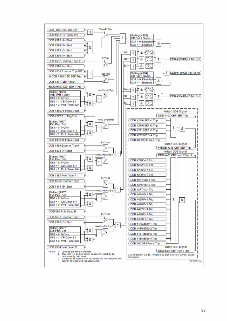
83
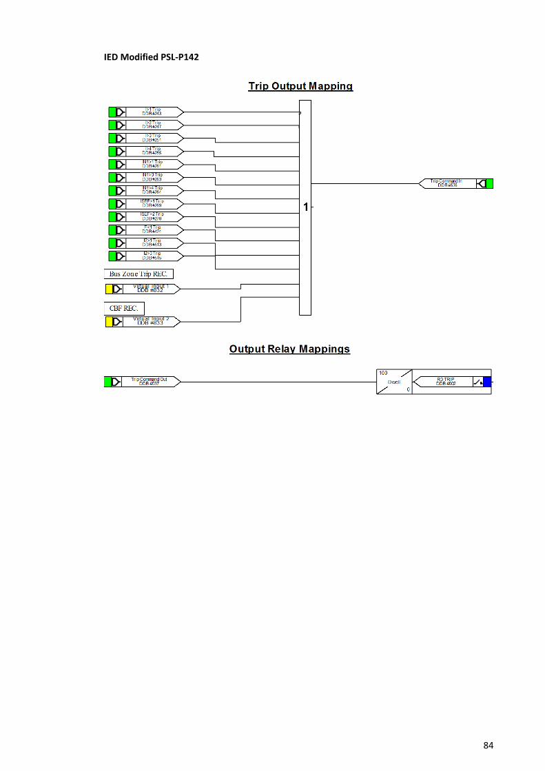
84
IED Modified PSL-P142

85
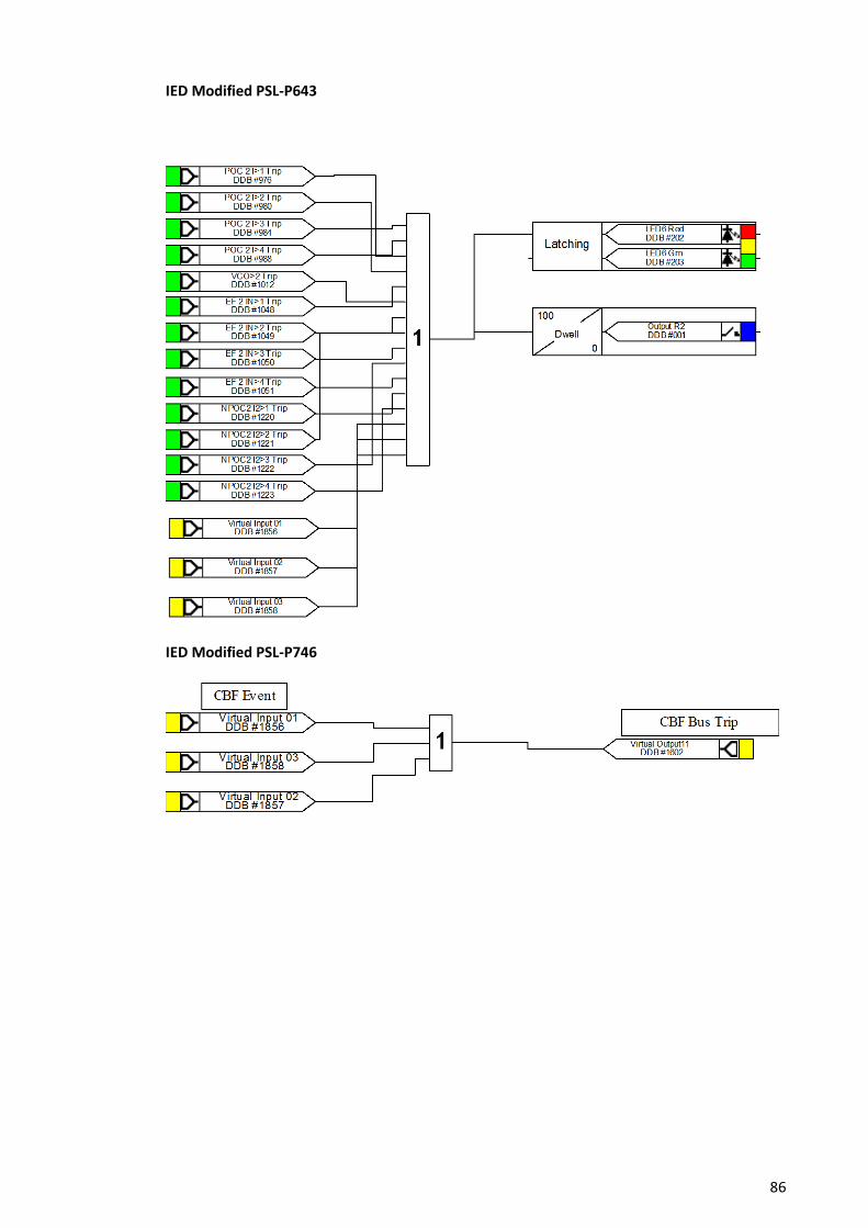
86
IED Modified PSL-P643
IED Modified PSL-P746
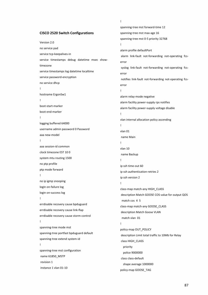
87
CISCO 2520 Switch Configurations
Version 2.0
no service pad
service tcp-keepalives-in
service timestamps debug datetime msec show-
timezone
service timestamps log datetime localtime
service password-encryption
no service dhcp
!
hostname ErgonSw1
!
boot-start-marker
boot-end-marker
!
logging buffered 64000
username admin password 0 Password
aaa new-model
!
aaa session-id common
clock timezone EST 10 0
system mtu routing 1500
no ptp profile
ptp mode forward
!
no ip igmp snooping
login on-failure log
login on-success log
!
errdisable recovery cause bpduguard
errdisable recovery cause link-flap
errdisable recovery cause storm-control
!
spanning-tree mode mst
spanning-tree portfast bpduguard default
spanning-tree extend system-id
!
spanning-tree mst configuration
name 61850_MSTP
revision 1
instance 1 vlan 01-10
!
spanning-tree mst forward-time 12
spanning-tree mst max-age 16
spanning-tree mst 0-5 priority 32768
!
alarm profile defaultPort
alarm link-fault not-forwarding not-operating fcs-
error
syslog link-fault not-forwarding not-operating fcs-
error
notifies link-fault not-forwarding not-operating fcs-
error
!
alarm relay-mode negative
alarm facility power-supply rps notifies
alarm facility power-supply voltage disable
!
vlan internal allocation policy ascending
!
vlan 01
name Main
!
vlan 10
name Backup
!
ip ssh time-out 60
ip ssh authentication-retries 2
ip ssh version 2
!
class-map match-any HIGH_CLASS
description Match GOOSE COS value for output QOS
match cos 4 5
class-map match-any GOOSE_CLASS
description Match Goose VLAN
match vlan 01
!
policy-map OUT_POLICY
description Limit total traffic to 10Mb for Relay
class HIGH_CLASS
priority
police 9000000
class class-default
shape average 1000000
policy-map GOOSE_TAG
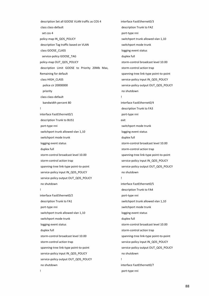
88
description Set all GOOSE VLAN traffic as COS 4
class class-default
set cos 4
policy-map IN_QOS_POLICY
description Tag traffic based on VLAN
class GOOSE_CLASS
service-policy GOOSE_TAG
policy-map OUT_QOS_POLICY
description Limit GOOSE to Priority 20Mb Max,
Remaining for default
class HIGH_CLASS
police cir 20000000
priority
class class-default
bandwidth percent 80
!
interface FastEthernet0/1
description Trunk to BUS1
port-type nni
switchport trunk allowed vlan 1,10
switchport mode trunk
logging event status
duplex full
storm-control broadcast level 10.00
storm-control action trap
spanning-tree link-type point-to-point
service-policy input IN_QOS_POLICY
service-policy output OUT_QOS_POLICY
no shutdown
!
interface FastEthernet0/2
description Trunk to FA1
port-type nni
switchport trunk allowed vlan 1,10
switchport mode trunk
logging event status
duplex full
storm-control broadcast level 10.00
storm-control action trap
spanning-tree link-type point-to-point
service-policy input IN_QOS_POLICY
service-policy output OUT_QOS_POLICY
no shutdown
!
interface FastEthernet0/3
description Trunk to FA2
port-type nni
switchport trunk allowed vlan 1,10
switchport mode trunk
logging event status
duplex full
storm-control broadcast level 10.00
storm-control action trap
spanning-tree link-type point-to-point
service-policy input IN_QOS_POLICY
service-policy output OUT_QOS_POLICY
no shutdown
!
interface FastEthernet0/4
description Trunk to FA3
port-type nni
exit
switchport mode trunk
logging event status
duplex full
storm-control broadcast level 10.00
storm-control action trap
spanning-tree link-type point-to-point
service-policy input IN_QOS_POLICY
service-policy output OUT_QOS_POLICY
no shutdown
!
interface FastEthernet0/5
description Trunk to FA4
port-type nni
switchport trunk allowed vlan 1,10
switchport mode trunk
logging event status
duplex full
storm-control broadcast level 10.00
storm-control action trap
spanning-tree link-type point-to-point
service-policy input IN_QOS_POLICY
service-policy output OUT_QOS_POLICY
no shutdown
!
interface FastEthernet0/7
port-type nni
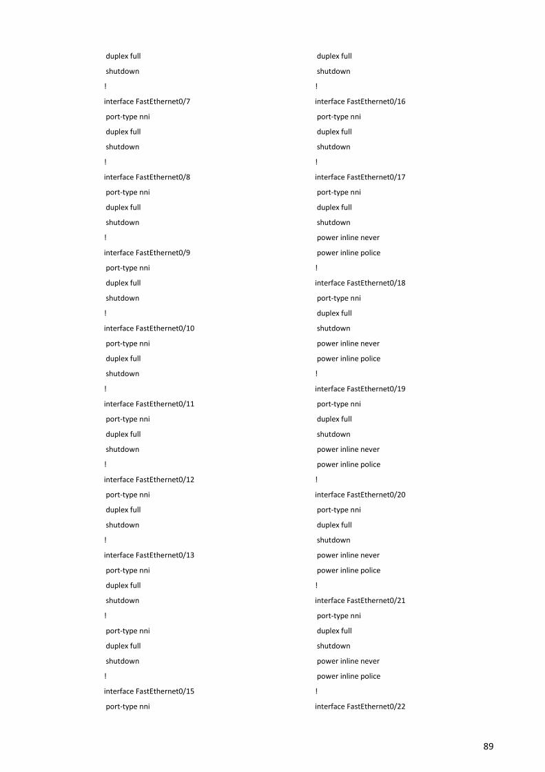
89
duplex full
shutdown
!
interface FastEthernet0/7
port-type nni
duplex full
shutdown
!
interface FastEthernet0/8
port-type nni
duplex full
shutdown
!
interface FastEthernet0/9
port-type nni
duplex full
shutdown
!
interface FastEthernet0/10
port-type nni
duplex full
shutdown
!
interface FastEthernet0/11
port-type nni
duplex full
shutdown
!
interface FastEthernet0/12
port-type nni
duplex full
shutdown
!
interface FastEthernet0/13
port-type nni
duplex full
shutdown
!
port-type nni
duplex full
shutdown
!
interface FastEthernet0/15
port-type nni
duplex full
shutdown
!
interface FastEthernet0/16
port-type nni
duplex full
shutdown
!
interface FastEthernet0/17
port-type nni
duplex full
shutdown
power inline never
power inline police
!
interface FastEthernet0/18
port-type nni
duplex full
shutdown
power inline never
power inline police
!
interface FastEthernet0/19
port-type nni
duplex full
shutdown
power inline never
power inline police
!
interface FastEthernet0/20
port-type nni
duplex full
shutdown
power inline never
power inline police
!
interface FastEthernet0/21
port-type nni
duplex full
shutdown
power inline never
power inline police
!
interface FastEthernet0/22
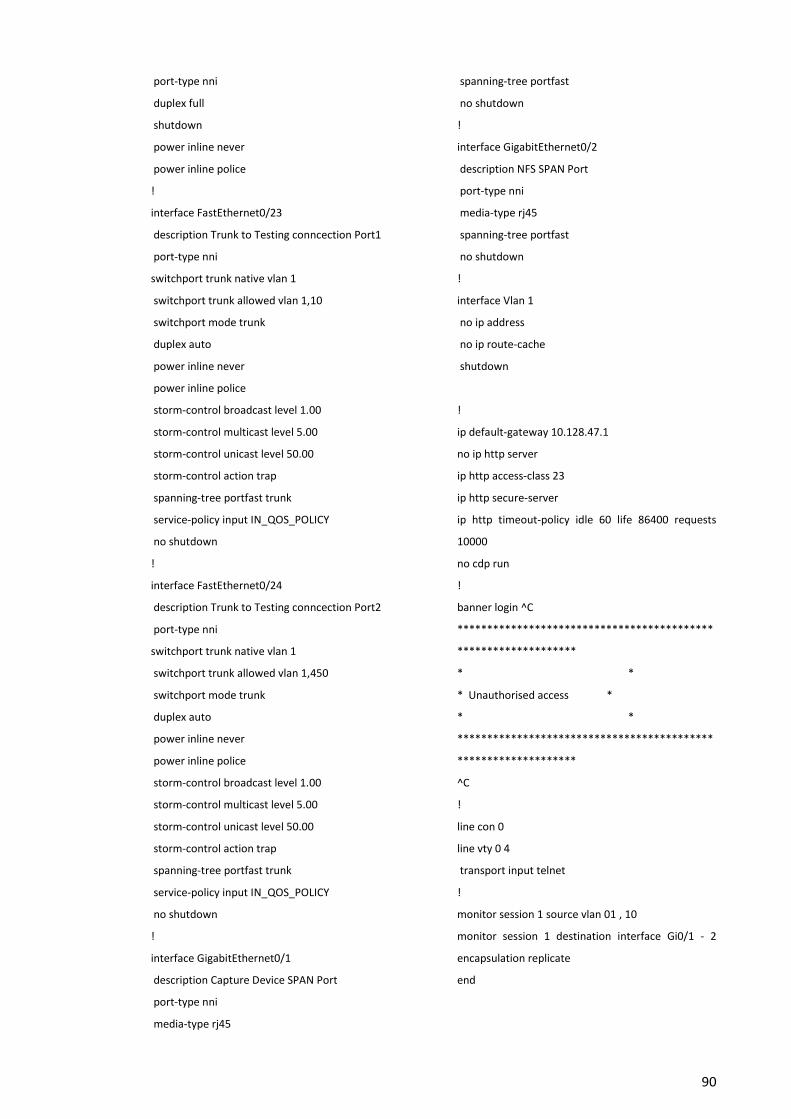
90
port-type nni
duplex full
shutdown
power inline never
power inline police
!
interface FastEthernet0/23
description Trunk to Testing conncection Port1
port-type nni
switchport trunk native vlan 1
switchport trunk allowed vlan 1,10
switchport mode trunk
duplex auto
power inline never
power inline police
storm-control broadcast level 1.00
storm-control multicast level 5.00
storm-control unicast level 50.00
storm-control action trap
spanning-tree portfast trunk
service-policy input IN_QOS_POLICY
no shutdown
!
interface FastEthernet0/24
description Trunk to Testing conncection Port2
port-type nni
switchport trunk native vlan 1
switchport trunk allowed vlan 1,450
switchport mode trunk
duplex auto
power inline never
power inline police
storm-control broadcast level 1.00
storm-control multicast level 5.00
storm-control unicast level 50.00
storm-control action trap
spanning-tree portfast trunk
service-policy input IN_QOS_POLICY
no shutdown
!
interface GigabitEthernet0/1
description Capture Device SPAN Port
port-type nni
media-type rj45
spanning-tree portfast
no shutdown
!
interface GigabitEthernet0/2
description NFS SPAN Port
port-type nni
media-type rj45
spanning-tree portfast
no shutdown
!
interface Vlan 1
no ip address
no ip route-cache
shutdown
!
ip default-gateway 10.128.47.1
no ip http server
ip http access-class 23
ip http secure-server
ip http timeout-policy idle 60 life 86400 requests
10000
no cdp run
!
banner login ^C
*******************************************
********************
* *
* Unauthorised access *
* *
*******************************************
********************
^C
!
line con 0
line vty 0 4
transport input telnet
!
monitor session 1 source vlan 01 , 10
monitor session 1 destination interface Gi0/1 - 2
encapsulation replicate
end
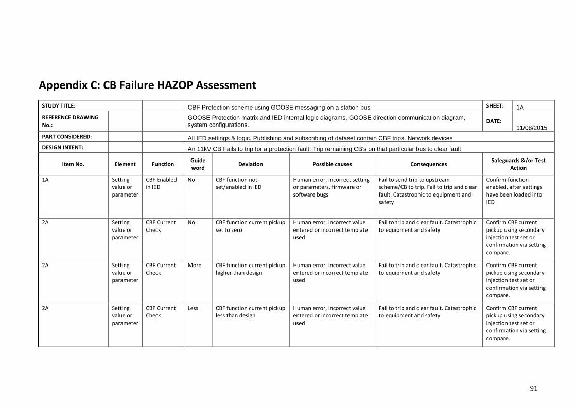
91
Appendix C: CB Failure HAZOP Assessment
STUDY TITLE: CBF Protection scheme using GOOSE messaging on a station bus SHEET: 1A
REFERENCE DRAWING No.:
GOOSE Protection matrix and IED internal logic diagrams, GOOSE direction communication diagram, system configurations.
DATE: 11/08/2015
PART CONSIDERED: All IED settings & logic. Publishing and subscribing of dataset contain CBF trips. Network devices
DESIGN INTENT: An 11kV CB Fails to trip for a protection fault. Trip remaining CB's on that particular bus to clear fault
Item No. Element Function Guide word
Deviation Possible causes Consequences Safeguards &/or Test
Action
1A Setting value or parameter
CBF Enabled in IED
No CBF function not set/enabled in IED
Human error, Incorrect setting or parameters, firmware or software bugs
Fail to send trip to upstream scheme/CB to trip. Fail to trip and clear fault. Catastrophic to equipment and safety
Confirm function enabled, after settings have been loaded into IED
2A Setting value or parameter
CBF Current Check
No CBF function current pickup set to zero
Human error, incorrect value entered or incorrect template used
Fail to trip and clear fault. Catastrophic to equipment and safety
Confirm CBF current pickup using secondary injection test set or confirmation via setting compare.
2A Setting value or parameter
CBF Current Check
More CBF function current pickup higher than design
Human error, incorrect value entered or incorrect template used
Fail to trip and clear fault. Catastrophic to equipment and safety
Confirm CBF current pickup using secondary injection test set or confirmation via setting compare.
2A Setting value or parameter
CBF Current Check
Less CBF function current pickup less than design
Human error, incorrect value entered or incorrect template used
Fail to trip and clear fault. Catastrophic to equipment and safety
Confirm CBF current pickup using secondary injection test set or confirmation via setting compare.
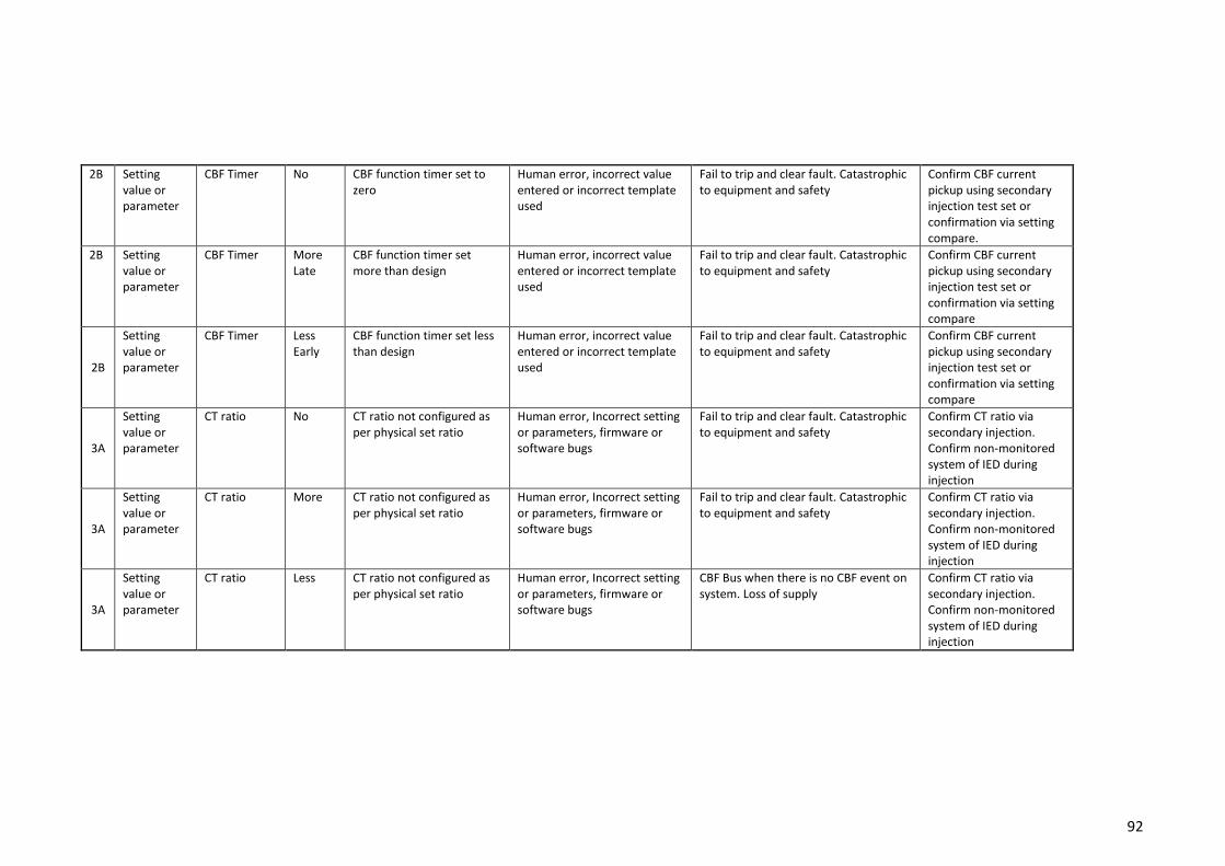
92
2B Setting value or parameter
CBF Timer No CBF function timer set to zero
Human error, incorrect value entered or incorrect template used
Fail to trip and clear fault. Catastrophic to equipment and safety
Confirm CBF current pickup using secondary injection test set or confirmation via setting compare.
2B Setting value or parameter
CBF Timer More Late
CBF function timer set more than design
Human error, incorrect value entered or incorrect template used
Fail to trip and clear fault. Catastrophic to equipment and safety
Confirm CBF current pickup using secondary injection test set or confirmation via setting compare
2B
Setting value or parameter
CBF Timer Less Early
CBF function timer set less than design
Human error, incorrect value entered or incorrect template used
Fail to trip and clear fault. Catastrophic to equipment and safety
Confirm CBF current pickup using secondary injection test set or confirmation via setting compare
3A
Setting value or parameter
CT ratio No CT ratio not configured as per physical set ratio
Human error, Incorrect setting or parameters, firmware or software bugs
Fail to trip and clear fault. Catastrophic to equipment and safety
Confirm CT ratio via secondary injection. Confirm non-monitored system of IED during injection
3A
Setting value or parameter
CT ratio More CT ratio not configured as per physical set ratio
Human error, Incorrect setting or parameters, firmware or software bugs
Fail to trip and clear fault. Catastrophic to equipment and safety
Confirm CT ratio via secondary injection. Confirm non-monitored system of IED during injection
3A
Setting value or parameter
CT ratio Less CT ratio not configured as per physical set ratio
Human error, Incorrect setting or parameters, firmware or software bugs
CBF Bus when there is no CBF event on system. Loss of supply
Confirm CT ratio via secondary injection. Confirm non-monitored system of IED during injection
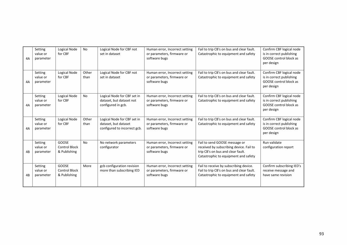
93
4A
Setting value or parameter
Logical Node for CBF
No Logical Node for CBF not set in dataset
Human error, Incorrect setting or parameters, firmware or software bugs
Fail to trip CB's on bus and clear fault. Catastrophic to equipment and safety
Confirm CBF logical node is in correct publishing GOOSE control block as per design
4A
Setting value or parameter
Logical Node for CBF
Other than
Logical Node for CBF not set in dataset
Human error, Incorrect setting or parameters, firmware or software bugs
Fail to trip CB's on bus and clear fault. Catastrophic to equipment and safety
Confirm CBF logical node is in correct publishing GOOSE control block as per design
4A
Setting value or parameter
Logical Node for CBF
No Logical Node for CBF set in dataset, but dataset not configured in gcb.
Human error, Incorrect setting or parameters, firmware or software bugs
Fail to trip CB's on bus and clear fault. Catastrophic to equipment and safety
Confirm CBF logical node is in correct publishing GOOSE control block as per design
4A
Setting value or parameter
Logical Node for CBF
Other than
Logical Node for CBF set in dataset, but dataset configured to incorrect gcb.
Human error, Incorrect setting or parameters, firmware or software bugs
Fail to trip CB's on bus and clear fault. Catastrophic to equipment and safety
Confirm CBF logical node is in correct publishing GOOSE control block as per design
4B
Setting value or parameter
GOOSE Control Block & Publishing
No No network parameters configurator
Human error, Incorrect setting or parameters, firmware or software bugs
Fail to send GOOSE message or received by subscribing device. Fail to trip CB's on bus and clear fault. Catastrophic to equipment and safety
Run validate configuration report
4B
Setting value or parameter
GOOSE Control Block & Publishing
More gcb configuration revision more than subscribing IED
Human error, Incorrect setting or parameters, firmware or software bugs
Fail to receive by subscribing device. Fail to trip CB's on bus and clear fault. Catastrophic to equipment and safety
Confirm subscribing IED's receive message and have same revision
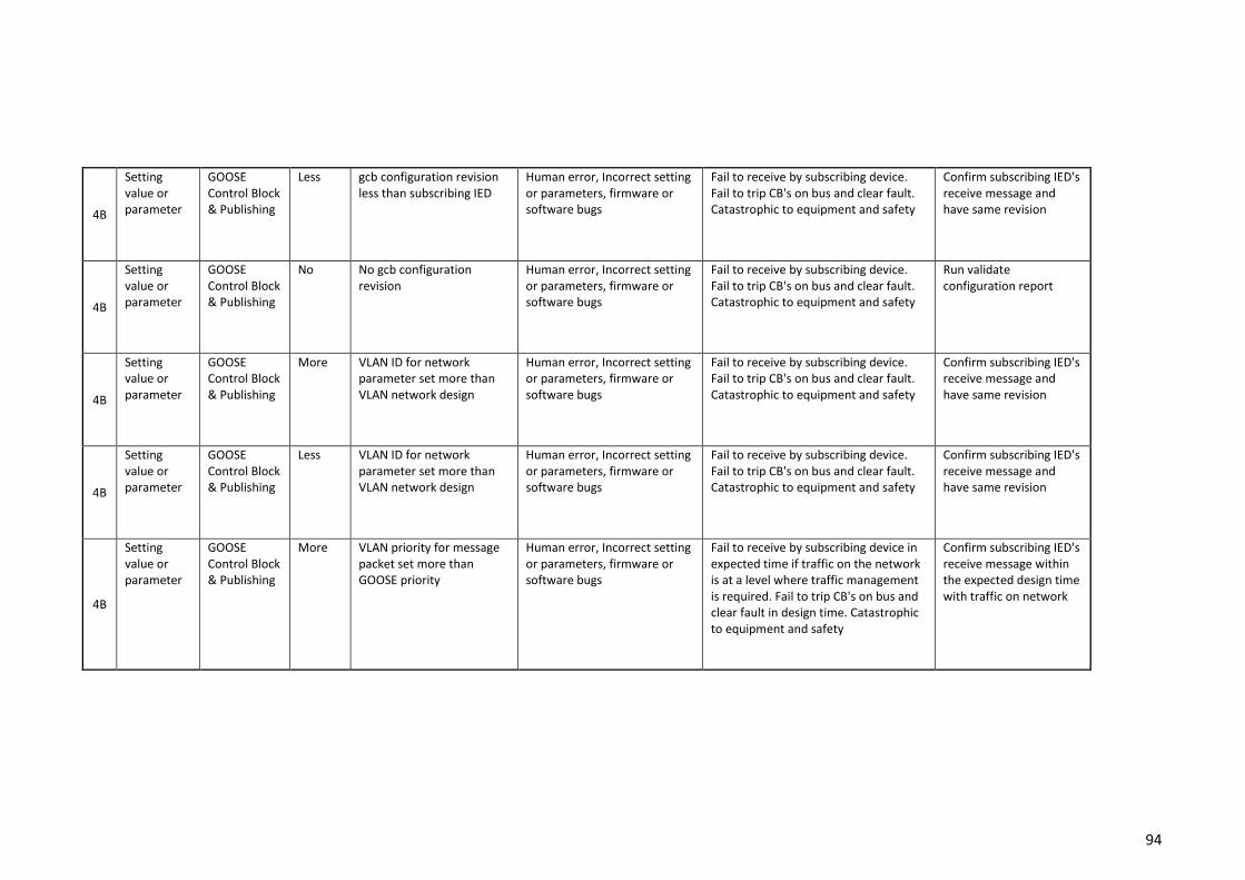
94
4B
Setting value or parameter
GOOSE Control Block & Publishing
Less gcb configuration revision less than subscribing IED
Human error, Incorrect setting or parameters, firmware or software bugs
Fail to receive by subscribing device. Fail to trip CB's on bus and clear fault. Catastrophic to equipment and safety
Confirm subscribing IED's receive message and have same revision
4B
Setting value or parameter
GOOSE Control Block & Publishing
No No gcb configuration revision
Human error, Incorrect setting or parameters, firmware or software bugs
Fail to receive by subscribing device. Fail to trip CB's on bus and clear fault. Catastrophic to equipment and safety
Run validate configuration report
4B
Setting value or parameter
GOOSE Control Block & Publishing
More VLAN ID for network parameter set more than VLAN network design
Human error, Incorrect setting or parameters, firmware or software bugs
Fail to receive by subscribing device. Fail to trip CB's on bus and clear fault. Catastrophic to equipment and safety
Confirm subscribing IED's receive message and have same revision
4B
Setting value or parameter
GOOSE Control Block & Publishing
Less VLAN ID for network parameter set more than VLAN network design
Human error, Incorrect setting or parameters, firmware or software bugs
Fail to receive by subscribing device. Fail to trip CB's on bus and clear fault. Catastrophic to equipment and safety
Confirm subscribing IED's receive message and have same revision
4B
Setting value or parameter
GOOSE Control Block & Publishing
More VLAN priority for message packet set more than GOOSE priority
Human error, Incorrect setting or parameters, firmware or software bugs
Fail to receive by subscribing device in expected time if traffic on the network is at a level where traffic management is required. Fail to trip CB's on bus and clear fault in design time. Catastrophic to equipment and safety
Confirm subscribing IED's receive message within the expected design time with traffic on network

95
4B
Setting value or parameter
GOOSE Control Block & Publishing
Less/After VLAN priority for message packet set less than GOOSE priority
Human error, Incorrect setting or parameters, firmware or software bugs
Fail to receive by subscribing device in expected time if traffic on the network is at a level where traffic management is required. Fail to trip CB's on bus and clear fault in design time. Catastrophic to equipment and safety
Confirm subscribing IED's receive message within the expected design time with traffic on network
5A
Network link
Fibre optic cable
No No data control signal passed
Failure to fibre optic cable or connectors
No data sent to receiving IED's. Fail to trip CB's on bus and clear fault
Confirm network communication using tools
5A
Network link
Fibre optic cable
Less Data is passed at a lower rate than intended
Failure to fibre optic cable or connectors
No data sent to receiving IED's. Fail to trip CB's on bus and clear fault
Confirm network communication using tools
6A
Station bus network switch
Port parameters
No Ingress Port not configurator
Human error, Incorrect setting or parameters, firmware or software bugs
No data sent to receiving IED's. Fail to trip CB's on bus and clear fault
Confirm switch parameters for network and GOOSE message
6A
Station bus network switch
Port parameters
No Ingress Port not configurator to designed VLAN ID, traffic control management and quality of service (QoS) parameters.
Human error, Incorrect setting or parameters, firmware or software bugs
No data sent to receiving IED's. Fail to trip CB's on bus and clear fault
Confirm switch parameters for network and GOOSE message
6A
Station bus network switch
Port parameters
After Late Ingress Port not configurator to designed VLAN ID, traffic control management and quality of service (QoS) parameters.
Human error, Incorrect setting or parameters, firmware or software bugs
No data sent to receiving IED's. Fail to trip CB's on bus and clear fault
Confirm switch parameters for network and GOOSE message
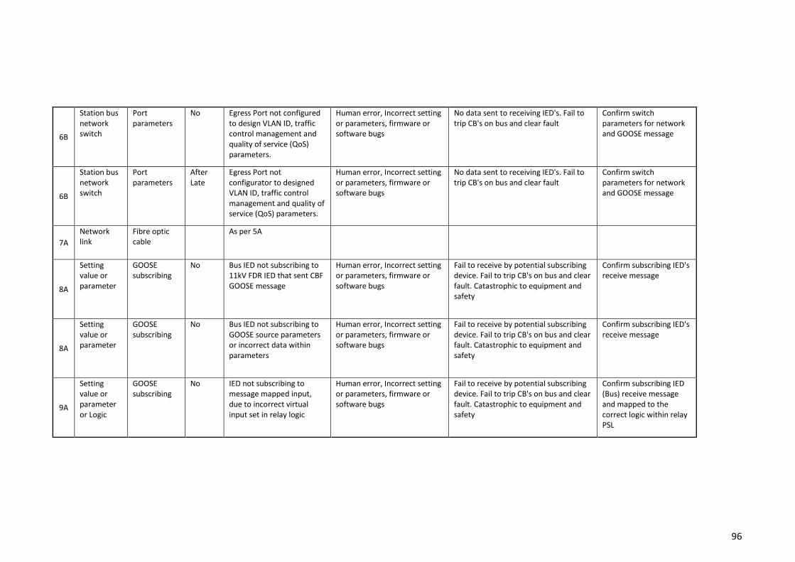
96
6B
Station bus network switch
Port parameters
No Egress Port not configured to design VLAN ID, traffic control management and quality of service (QoS) parameters.
Human error, Incorrect setting or parameters, firmware or software bugs
No data sent to receiving IED's. Fail to trip CB's on bus and clear fault
Confirm switch parameters for network and GOOSE message
6B
Station bus network switch
Port parameters
After Late
Egress Port not configurator to designed VLAN ID, traffic control management and quality of service (QoS) parameters.
Human error, Incorrect setting or parameters, firmware or software bugs
No data sent to receiving IED's. Fail to trip CB's on bus and clear fault
Confirm switch parameters for network and GOOSE message
7A
Network link
Fibre optic cable
As per 5A
8A
Setting value or parameter
GOOSE subscribing
No Bus IED not subscribing to 11kV FDR IED that sent CBF GOOSE message
Human error, Incorrect setting or parameters, firmware or software bugs
Fail to receive by potential subscribing device. Fail to trip CB's on bus and clear fault. Catastrophic to equipment and safety
Confirm subscribing IED's receive message
8A
Setting value or parameter
GOOSE subscribing
No Bus IED not subscribing to GOOSE source parameters or incorrect data within parameters
Human error, Incorrect setting or parameters, firmware or software bugs
Fail to receive by potential subscribing device. Fail to trip CB's on bus and clear fault. Catastrophic to equipment and safety
Confirm subscribing IED's receive message
9A
Setting value or parameter or Logic
GOOSE subscribing
No IED not subscribing to message mapped input, due to incorrect virtual input set in relay logic
Human error, Incorrect setting or parameters, firmware or software bugs
Fail to receive by potential subscribing device. Fail to trip CB's on bus and clear fault. Catastrophic to equipment and safety
Confirm subscribing IED (Bus) receive message and mapped to the correct logic within relay PSL
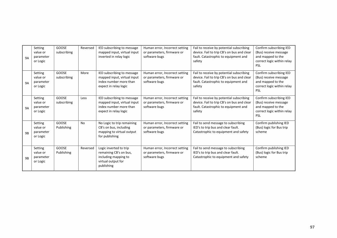
97
9A
Setting value or parameter or Logic
GOOSE subscribing
Reversed IED subscribing to message mapped input, virtual input inverted in relay logic
Human error, Incorrect setting or parameters, firmware or software bugs
Fail to receive by potential subscribing device. Fail to trip CB's on bus and clear fault. Catastrophic to equipment and safety
Confirm subscribing IED (Bus) receive message and mapped to the correct logic within relay PSL
9A
Setting value or parameter or Logic
GOOSE subscribing
More IED subscribing to message mapped input, virtual input index number more than expect in relay logic
Human error, Incorrect setting or parameters, firmware or software bugs
Fail to receive by potential subscribing device. Fail to trip CB's on bus and clear fault. Catastrophic to equipment and safety
Confirm subscribing IED (Bus) receive message and mapped to the correct logic within relay PSL
9A
Setting value or parameter or Logic
GOOSE subscribing
Less IED subscribing to message mapped input, virtual input index number more than expect in relay logic
Human error, Incorrect setting or parameters, firmware or software bugs
Fail to receive by potential subscribing device. Fail to trip CB's on bus and clear fault. Catastrophic to equipment and safety
Confirm subscribing IED (Bus) receive message and mapped to the correct logic within relay PSL
9B
Setting value or parameter or Logic
GOOSE Publishing
No No Logic to trip remaining CB's on bus, including mapping to virtual output for publishing
Human error, Incorrect setting or parameters, firmware or software bugs
Fail to send message to subscribing IED's to trip bus and clear fault. Catastrophic to equipment and safety
Confirm publishing IED (Bus) logic for Bus trip scheme
9B
Setting value or parameter or Logic
GOOSE Publishing
Reversed Logic inverted to trip remaining CB's on bus, including mapping to virtual output for publishing
Human error, Incorrect setting or parameters, firmware or software bugs
Fail to send message to subscribing IED's to trip bus and clear fault. Catastrophic to equipment and safety
Confirm publishing IED (Bus) logic for Bus trip scheme
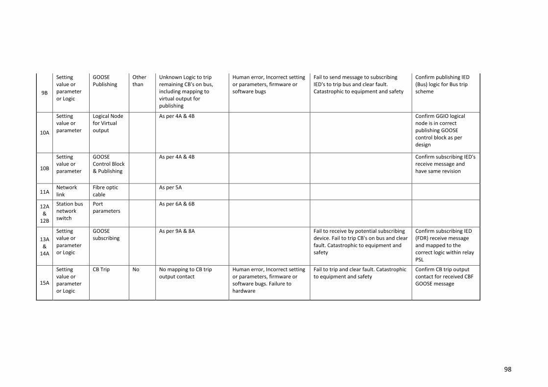
98
9B
Setting value or parameter or Logic
GOOSE Publishing
Other than
Unknown Logic to trip remaining CB's on bus, including mapping to virtual output for publishing
Human error, Incorrect setting or parameters, firmware or software bugs
Fail to send message to subscribing IED's to trip bus and clear fault. Catastrophic to equipment and safety
Confirm publishing IED (Bus) logic for Bus trip scheme
10A
Setting value or parameter
Logical Node for Virtual output
As per 4A & 4B Confirm GGIO logical node is in correct publishing GOOSE control block as per design
10B
Setting value or parameter
GOOSE Control Block & Publishing
As per 4A & 4B Confirm subscribing IED's receive message and have same revision
11A Network link
Fibre optic cable
As per 5A
12A &
12B
Station bus network switch
Port parameters
As per 6A & 6B
13A &
14A
Setting value or parameter or Logic
GOOSE subscribing
As per 9A & 8A Fail to receive by potential subscribing device. Fail to trip CB's on bus and clear fault. Catastrophic to equipment and safety
Confirm subscribing IED (FDR) receive message and mapped to the correct logic within relay PSL
15A
Setting value or parameter or Logic
CB Trip No No mapping to CB trip output contact
Human error, Incorrect setting or parameters, firmware or software bugs. Failure to hardware
Fail to trip and clear fault. Catastrophic to equipment and safety
Confirm CB trip output contact for received CBF GOOSE message
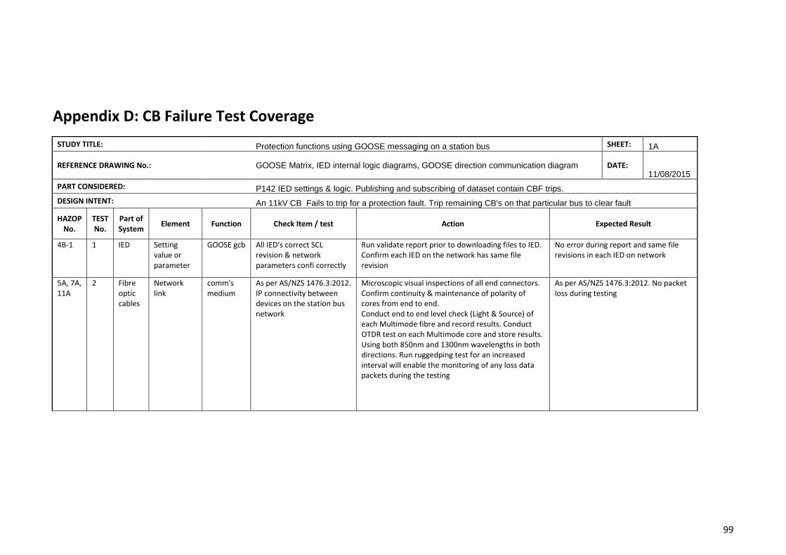
99
Appendix D: CB Failure Test Coverage
STUDY TITLE: Protection functions using GOOSE messaging on a station bus SHEET: 1A
REFERENCE DRAWING No.: GOOSE Matrix, IED internal logic diagrams, GOOSE direction communication diagram DATE: 11/08/2015
PART CONSIDERED: P142 IED settings & logic. Publishing and subscribing of dataset contain CBF trips.
DESIGN INTENT: An 11kV CB Fails to trip for a protection fault. Trip remaining CB's on that particular bus to clear fault
HAZOP No.
TEST No.
Part of System
Element Function Check Item / test Action Expected Result
4B-1 1 IED Setting value or parameter
GOOSE gcb All IED's correct SCL revision & network parameters confi correctly
Run validate report prior to downloading files to IED. Confirm each IED on the network has same file revision
No error during report and same file revisions in each IED on network
5A, 7A, 11A
2 Fibre optic cables
Network link
comm's medium
As per AS/NZS 1476.3:2012. IP connectivity between devices on the station bus network
Microscopic visual inspections of all end connectors. Confirm continuity & maintenance of polarity of cores from end to end. Conduct end to end level check (Light & Source) of each Multimode fibre and record results. Conduct OTDR test on each Multimode core and store results. Using both 850nm and 1300nm wavelengths in both directions. Run ruggedping test for an increased interval will enable the monitoring of any loss data packets during the testing
As per AS/NZS 1476.3:2012. No packet loss during testing
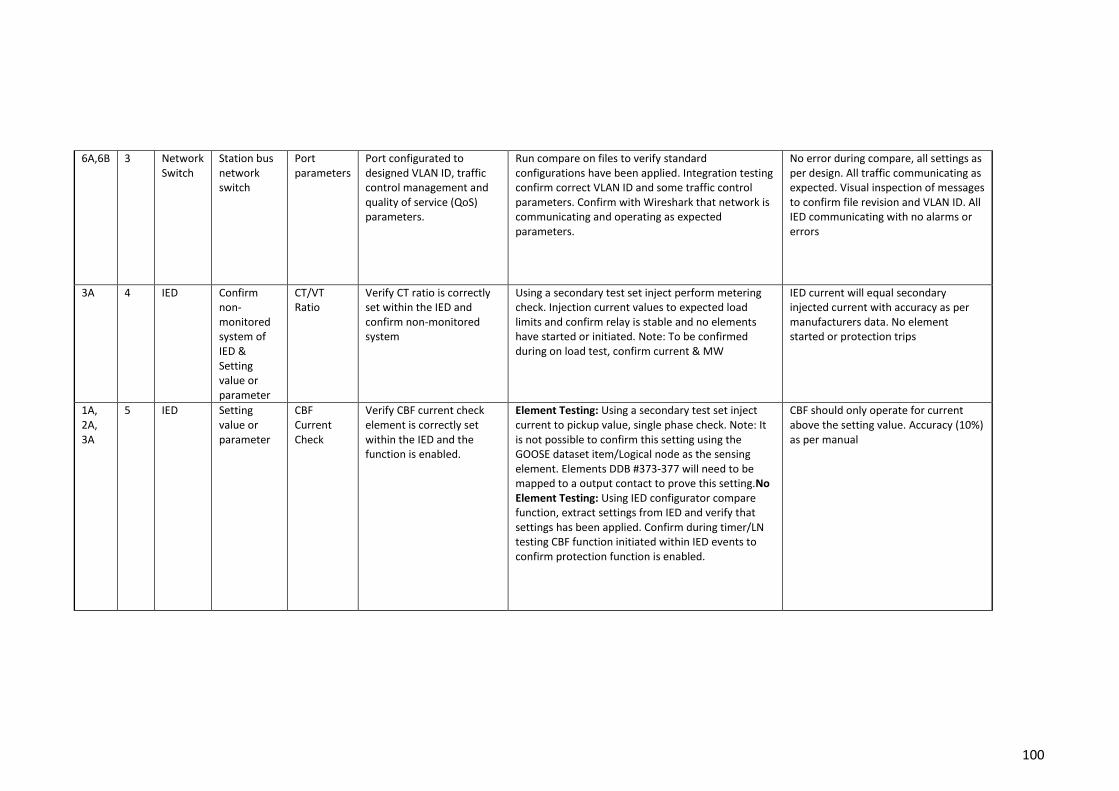
100
6A,6B 3 Network Switch
Station bus network switch
Port parameters
Port configurated to designed VLAN ID, traffic control management and quality of service (QoS) parameters.
Run compare on files to verify standard configurations have been applied. Integration testing confirm correct VLAN ID and some traffic control parameters. Confirm with Wireshark that network is communicating and operating as expected parameters.
No error during compare, all settings as per design. All traffic communicating as expected. Visual inspection of messages to confirm file revision and VLAN ID. All IED communicating with no alarms or errors
3A 4 IED Confirm non-monitored system of IED & Setting value or parameter
CT/VT Ratio
Verify CT ratio is correctly set within the IED and confirm non-monitored system
Using a secondary test set inject perform metering check. Injection current values to expected load limits and confirm relay is stable and no elements have started or initiated. Note: To be confirmed during on load test, confirm current & MW
IED current will equal secondary injected current with accuracy as per manufacturers data. No element started or protection trips
1A, 2A, 3A
5 IED Setting value or parameter
CBF Current Check
Verify CBF current check element is correctly set within the IED and the function is enabled.
Element Testing: Using a secondary test set inject current to pickup value, single phase check. Note: It is not possible to confirm this setting using the GOOSE dataset item/Logical node as the sensing element. Elements DDB #373-377 will need to be mapped to a output contact to prove this setting.No Element Testing: Using IED configurator compare function, extract settings from IED and verify that settings has been applied. Confirm during timer/LN testing CBF function initiated within IED events to confirm protection function is enabled.
CBF should only operate for current above the setting value. Accuracy (10%) as per manual
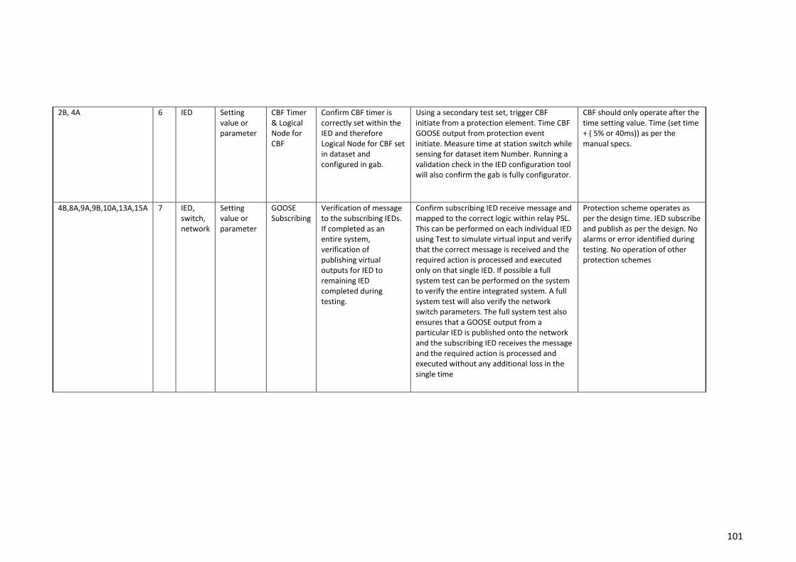
101
2B, 4A 6 IED Setting value or parameter
CBF Timer & Logical Node for CBF
Confirm CBF timer is correctly set within the IED and therefore Logical Node for CBF set in dataset and configured in gab.
Using a secondary test set, trigger CBF initiate from a protection element. Time CBF GOOSE output from protection event initiate. Measure time at station switch while sensing for dataset item Number. Running a validation check in the IED configuration tool will also confirm the gab is fully configurator.
CBF should only operate after the time setting value. Time (set time + ( 5% or 40ms)) as per the manual specs.
4B,8A,9A,9B,10A,13A,15A 7 IED, switch, network
Setting value or parameter
GOOSE Subscribing
Verification of message to the subscribing IEDs. If completed as an entire system, verification of publishing virtual outputs for IED to remaining IED completed during testing.
Confirm subscribing IED receive message and mapped to the correct logic within relay PSL. This can be performed on each individual IED using Test to simulate virtual input and verify that the correct message is received and the required action is processed and executed only on that single IED. If possible a full system test can be performed on the system to verify the entire integrated system. A full system test will also verify the network switch parameters. The full system test also ensures that a GOOSE output from a particular IED is published onto the network and the subscribing IED receives the message and the required action is processed and executed without any additional loss in the single time
Protection scheme operates as per the design time. IED subscribe and publish as per the design. No alarms or error identified during testing. No operation of other protection schemes

102
Appendix E: Project Management & Safety
Project Schedule
The following project schedule has been developed to manage the project milestones,
activities and deliverables. Table 7 illustrates the developed project schedule..
Table 7: Project Schedule
Risk Assessment (DTRMP Template)
The laboratory work will be completed at Ergon Energy’s Protection Group test laboratory in
Townsville. Ergon Energy’s Daily Task Risk Assessment Plan (DTRMP) will be used as the risk
assessment tool for all laboratory work. Prior to performing any work in the laboratory any
hazards associated with tasks in the laboratory shall be identified and assessed with
appropriate control measures implemented and documented in accordance with a Daily Task
Risk Assessment Plan (DTRMP). If any risks cannot be managed or reduced to an acceptable
level the work will need to stop immediately. Hazards will be assessed according to the DTRMP

103
level of risk matrix that will identify the likelihood and consequence of the hazard. The level of
risk matric is shown in Table 8
Table 8: DTRMP level of risk matrix
If the hazard falls within the Medium, High or Extreme level, additional control measures will
need to be set in place. With additional control measures in place the residual level of risk will
be assessed according to the DTRMP level of risk matrix that will identify the likelihood and
consequence of the hazard with the additional control measures. If any risks cannot be
managed or reduced to an acceptable level (Low or Very Low) the work will need to stop
immediately. The two main activities that will be performed in the laboratory will be the use of
hand tools and test equipment. The hazards and potential consequences associated with
performing these tasks and additional control measures to eliminate or reduce the residual
risk are identified in Table 9. Appendix B provides a copy of Ergon Energy’s DTRMP.
Table 9: WHS Risk Control Guide
Activity Hazard Concequences Control Measure
• Loss of control • Sprain, strain injury 1. Competence in tool use
• Misuse • Cuts, abrasions 2. Tool used for intended purpose
• Tool / equipment damage 3. Required PPE w orn
4. Ensure tools f it for purpose and operated in
competent manner
5. Tools maintained in serviceable condition
6. Defective tools removed from service, tagged as
defective and quarantined
• Personal injury 1. Required PPE w orn
• Electric shock
2. Test equipment w ithin test date and used by
competent persons
• Burns
3. Test equipment used by authorised persons
(w here required)
• Plant or property damage
5. Check all connections before use
6. Alw ays physically isolate test equipment from input
supply source w hen not in use
Hand Tool Operation
Testing & Test
Equipment
• Electrical & Inadvertent
contact w ith test voltage
/ current
4. Comply w ith electrical industry codes of practice
requirements for w ork on or near LV systems. These
include:• Tape off / barricade adjacent panels• Isolate
danger tag circuits• Test before you touch• Don’t use
exposed leads or terminals• Comply w ith AS4836• Use
LV mats, covers, barriers and 00 gloves, if required, as
determined by a risk assessment• Have LV rescue kit
available at w ork site

104

105
Related Documents