Technical Report 2 University of North Carolina’s Imaging Research Building Daniel R. Hesington, LEED AP Structural Option Consultant- Dr. Thomas Boothby October 5, 2009

Welcome message from author
This document is posted to help you gain knowledge. Please leave a comment to let me know what you think about it! Share it to your friends and learn new things together.
Transcript

Technical Report 2
University of North Carolina’s
Imaging Research Building
Daniel R. Hesington, LEED AP
Structural Option
Consultant- Dr. Thomas Boothby
October 5, 2009

Technical Report 2 UNC- IRB Daniel R. Hesington Chapel Hill, NC
Page2|32
Table of Contents
Executive Summary……………………………………………………………………………..3
Introduction……………………………………………………………………………………...4
Architectural Design Concepts………………………………………………………………....4
Structural System………………………………………………………………………………..5
Foundation………………………………………………………………………………..5
Superstructure…………………………………………………………………………….5
Lateral System…………………………………………………………………………….7
Codes and Design Standards………………………………………………………………..…..9
Loads……………………………………………………………………………………...……..10
Gravity Loads……………………………………………………………………….……10
Wind Loads………………………………………………………………………………11
Seismic Loads.………………………………………………………………………...…12
Spot Checks……………………………………………………………………………………..15
Conclusion………………………………………………………………………………………17
Appendix A – Gravity Load Calculations…...………………………………………………..18
Appendix B – Wind Load Calculations...……………………………………………………..29
Appendix C – Seismic Load Calculations...…………………………………………………...27
Appendix D – Spot Checks……………………………………………………………………..34

Technical Report 2 UNC- IRB Daniel R. Hesington Chapel Hill, NC
Page3|32
Executive Summary
This report was created to be a pro-con study of the existing floor system, and three additional floor systems. Each option was examined using a typical 21’-3” by 31’-4” bay as the basis for analysis. The existing floor system is a 6” one-way cast-in-place slab with #4@12 top and bottom for the typical interior bay. An overview of this system and its advantages and disadvantages are provided in the report.
The three alternate systems that were analyzed were:
- Non-composite steel framing - Composite steel framing - Hollow core precast concrete on steel beams
The non-composite steel framing was designed using the AISC 13th edition Steel Construction Manual and the Vulcraft Steel Roof Floor Deck Guide. The design for the typical interior bay was composed of 2C18 metal deck with a 6” slab, W16X31 beams, and W24X76 girders. The composite steel framing was designed using RAM Structural System and Vulcraft 2VL composite deck. It was found that W10X12’s with (14) ¾” shear studs and a ¾” camber would work for the beams, and W21x44’s with (50) shear studs a ¾” camber would work for the girders. The 4’-0” x 6” hollow core precast plank with 2” topping were selected from the PCI Design Handbook and the supporting girders were determined to be W24X76’s when optimized, the same as the non-composite floor system.
The advantages and disadvantages of each of the floor systems were discussed for each framing system, and it was determined that both the non-composite steel framing and the hollow core system were not feasible due to several reasons outlined in the report. However, the composite steel system was determined to be a viable option for future exploration. It’s lightweight, not as labor intensive as a cast-in-place concrete slab, and therefore relatively cost effective to construct. The one major disadvantage though is that on the lower levels, stainless steel would need to be used for the framing due to the magnetic interference with the imaging equipment. This problem can be overcome though if a concrete base is used for the subfloors (where the imaging equipment is located), and a steel frame system is used for the floors above.

Technical Report 2 UNC- IRB Daniel R. Hesington Chapel Hill, NC
Page4|32
Introduction
This pro-con structural study of alternate floor systems examines the existing floor framing of the University of North Carolina Imaging Research building that was designed by Mulkey Engineers and Consultants, and analyzes three other possible systems. The existing design is a 6” one-way cast-in-place concrete slab while the alternate systems that were studied include non-composite steel framing, hollow core precast planks on steel beams, and a two-way cast-in-place slab. Gravity loads determined in Technical Report 1 were used in the design to help determine slab thicknesses, member sizes and necessary reinforcement. The main focus of this report is compare and contrast the advantages and disadvantages concerning constructability, system depth, system weight, fire protection, cost, and various other criteria to determine which systems may be possible topics for the structural proposal required by Senior Thesis.
The relevant codes used for this analysis are:
Codes & Design Standards
Applied to original design:
2009 North Carolina State Building Code (2006 International Building Code with revisions)
American Concrete Institute (ACI 318-05), Building Code Requirements for Structural Concrete
Substituted for thesis analysis:
American Society for Civil Engineers (ASCE 7-05), Minimum Design Loads for Buildings and Other Structures, 2005
American Concrete Institute (ACI 318-08), Building Code Requirements for Structural Concrete
Material Strength Requirement Summary:
Concrete/Reinforcing Steel (28 day compressive strength)
• Elevated Slabs on Metal Deck: 3500 psi • Elevated Slabs and Beams: 5000 psi • Columns, Shear Walls: 7000 psi • Basement Walls, Site Walls: 7000 psi • Slab on Grade, Footings, Grade Beams: 4000 psi • Reinforcement: 60 ksi

Technical Report 2 UNC- IRB Daniel R. Hesington Chapel Hill, NC
Page5|32
Architectural Design Concepts
The Imaging Research Building at UNC Chapel Hill was designed by the architecture firm Perkins + Will. Its primary usage is the driving force behind many of the structural decisions for the project. Once it is open, it will contain the most advanced imaging equipment in any one spot in the world. First, the two subgrade floors house several heavy pieces of imaging research equipment that have large Gaussian fields. Because of this, foundations, walls, and slabs were made thicker than usual, which will result in the use of mass concrete pouring techniques to be required when constructed. For example, the foundation where a 1.5GHZ NMR machine will sit required a 6’ thick mat footing.
Above grade you will find typical bays sizes of 21’-4” by 21’-4”, and 21’-4” by 31’-4” driven by the laboratory space requirements on every floor. A bridge also connects the new imaging research facility to existing Lineberger Cancer Center on the second floor. At the eighth floor, a large area houses all of the mechanical equipment with a partial mezzanine at the floor above, which services all of the imaging and laboratory equipment below. These architectural and usage restraints have a generous effect on the structural system as noted below, and hopefully in future technical reports.
Structural System
Foundation
The geotechnical engineering study was performed by Tai and Associates on November 12, 2008. The study indicates that the subsurface materials on the site consist of pavement and topsoil, fill, residual soil, weathered rock, and rock and boulders. Based on this composition, Tai and Associates were confident in giving Mulkey a net allowable bearing pressure of 6000 pounds per square foot to use in their foundation calculations.
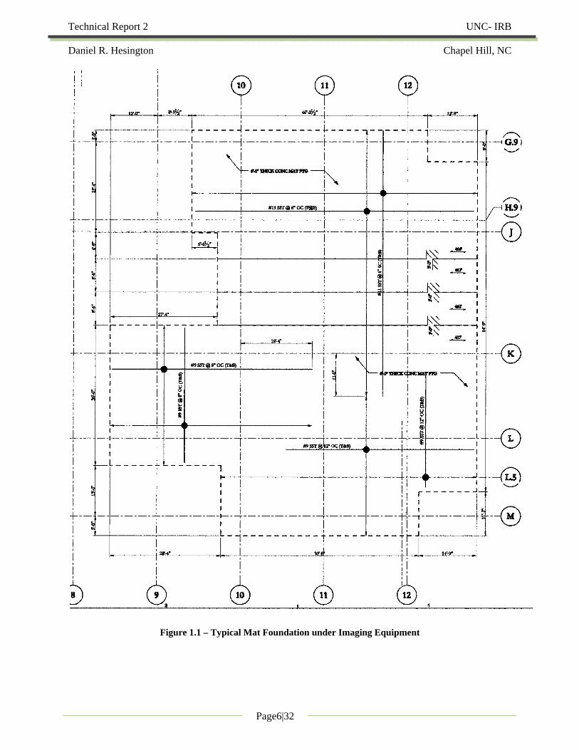
Because of this allowable bearing pressure, Mulkey had to be creative with their foundation design. The result is a mixture of spread footings under the columns, and a combination of spread and mat footings under the large imaging research equipment and shear walls. The walls below grade range from 18” to 36” in thickness¸ and in one location a 36” wall spans both subgrade floors to the first floor unbraced. An example of a typical mat footing can be seen in Figure 1.1. As with the other mat footings, this one is combined and sits under two pieces of large imaging equipment. It is 6’-0” thick and also services a shear wall that steps 6’ in elevation. Another area of note in the foundation design is a 6’-0” thick concrete footing which will service a cyclotron, another heavy piece of imaging equipment.
Technical Report 2 UNC- IRB Daniel R. Hesington Chapel Hill, NC
Page6|32
Figure 1.1 – Typical Mat Foundation under Imaging Equipment

Technical Report 2 UNC- IRB Daniel R. Hesington Chapel Hill, NC
Page7|32
Superstructure
The first floor and the floors above to the eighth floor is a 6” one-way cast-in-place slab (NWC) with a compressive strength (f’c) of 5 ksi. The beams on these levels are mostly 18”x20” T-Beams, which change directions at the re-entrant corner where the building changes directions. The girder dimensions vary, but are typically 28”x30”.
Most of the columns in the Imaging Research Building are 20”x20” square columns with #3 ties above the first floor, and 24”x24” below grade, with all them having a compressive strength of 7 ksi. The typical frame consists of four bays with three of them being approximately twenty feet in width and the other being thirty feet in width to accommodate the laboratories that occupy these spaces on almost every floor of the building.
For more detail on the superstructure a section of the third floor framing is provided in figure 2.1 for reference.
Figure 1.2 - Third Floor Framing
Technical Report 2 UNC- IRB Daniel R. Hesington Chapel Hill, NC
Page8|32
Lateral System
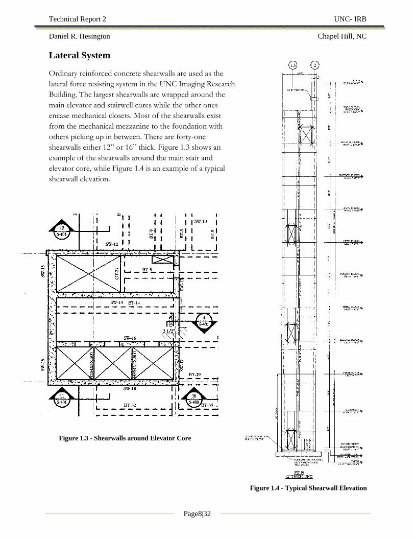
Ordinary reinforced concrete shearwalls are used as the lateral force resisting system in the UNC Imaging Research Building. The largest shearwalls are wrapped around the main elevator and stairwell cores while the other ones encase mechanical closets. Most of the shearwalls exist from the mechanical mezzanine to the foundation with others picking up in between. There are forty-one shearwalls either 12” or 16” thick. Figure 1.3 shows an example of the shearwalls around the main stair and elevator core, while Figure 1.4 is an example of a typical shearwall elevation.
Figure 1.3 - Shearwalls around Elevator Core
Figure 1.4 - Typical Shearwall Elevation
Technical Report 2 UNC- IRB Daniel R. Hesington Chapel Hill, NC
Page9|32
Loads
Gravity Loads
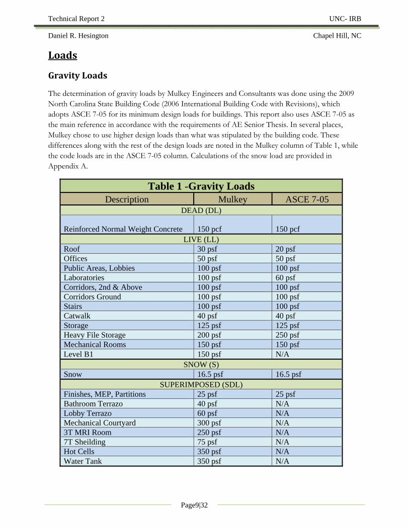
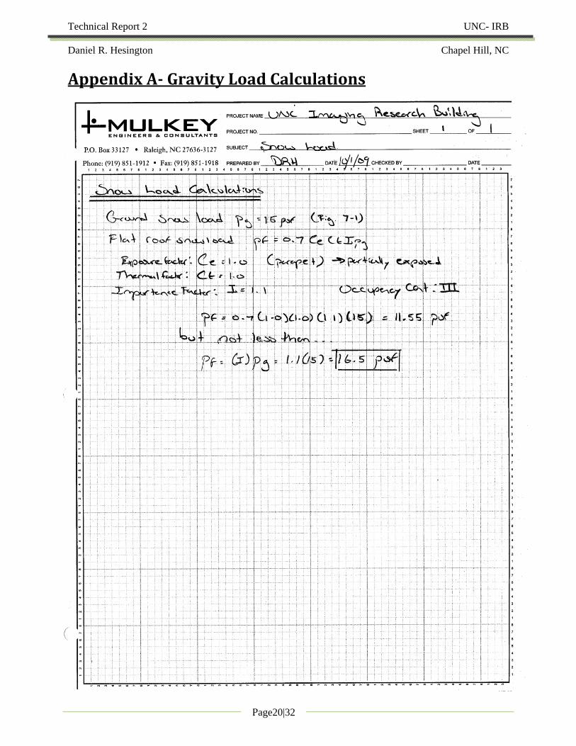
The determination of gravity loads by Mulkey Engineers and Consultants was done using the 2009 North Carolina State Building Code (2006 International Building Code with Revisions), which adopts ASCE 7-05 for its minimum design loads for buildings. This report also uses ASCE 7-05 as the main reference in accordance with the requirements of AE Senior Thesis. In several places, Mulkey chose to use higher design loads than what was stipulated by the building code. These differences along with the rest of the design loads are noted in the Mulkey column of Table 1, while the code loads are in the ASCE 7-05 column. Calculations of the snow load are provided in Appendix A.
Table 1 -Gravity Loads Description Mulkey ASCE 7-05
DEAD (DL)
Reinforced Normal Weight Concrete 150 pcf 150 pcf LIVE (LL)
Roof 30 psf 20 psf Offices 50 psf 50 psf Public Areas, Lobbies 100 psf 100 psf Laboratories 100 psf 60 psf Corridors, 2nd & Above 100 psf 100 psf Corridors Ground 100 psf 100 psf Stairs 100 psf 100 psf Catwalk 40 psf 40 psf Storage 125 psf 125 psf Heavy File Storage 200 psf 250 psf Mechanical Rooms 150 psf 150 psf Level B1 150 psf N/A
SNOW (S) Snow 16.5 psf 16.5 psf
SUPERIMPOSED (SDL) Finishes, MEP, Partitions 25 psf 25 psf Bathroom Terrazo 40 psf N/A Lobby Terrazo 60 psf N/A Mechanical Courtyard 300 psf N/A 3T MRI Room 250 psf N/A 7T Sheilding 75 psf N/A Hot Cells 350 psf N/A Water Tank 350 psf N/A

Technical Report 2 UNC- IRB Daniel R. Hesington Chapel Hill, NC
Page10|32
Floor Systems
OneWay Reinforced CastInPlace – Existing
Material Properties: Loading:
Concrete: 6” slab (NWC) Dead (self weight): 75 psf 20”x20” columns Live: 100 psf f’c = 5000 psi Superimposed: 25 psf Reinforcement: fy = 60,000 psi Description
This one-way reinforced cast-in-place floor system designed by Mulkey Engineering is a 6” NWC slab with ______________. The typical interior bay that was considered for this analysis features 18”x20” beams at 7’-10” on center and 28”x30” girders. Because of the size of the floorplan of the building, a detail of the bay analyzed is shown in figure ___.
An analysis for this floor system was done at the ___ floor using RAM Structural System software. Included for this technical report from the RAM output are the stresses and code checks while basic calculations to check minimum thickness for deflection control are done by hand. Both the computer output and hand calculations can be found in Appendix ___.
Advantages
The one-way cast-in-place slab is a simple floor system to design and construct. Therefore, it is relatively inexpensive both in design and construction. Also, it is works for heavier live loads as in the Imaging Research Building because there is very little deflection when used in combination with beams. But more importantly, penetrations in the slab cause few structural problems because there is not a lot of large rebar or tendons running through the slab, and it is easy to reinforce around them after they have been created. This is very important on a job like the Imaging Research Building where there are a number of mechanical systems and equipment lines for the imaging laboratory equipment penetrating through the floors. Therefore, the one-way cast-in-place slab was a logical choice for Mulkey.

Technical Report 2 UNC- IRB Daniel R. Hesington Chapel Hill, NC
Page11|32
Disadvantages
While there are some obvious advantages that make the one-way floor slab a logical choice for the Imaging Research Building, there are a couple disadvantages to it as well. First, since it is a cast-in-place beam and slab system it’s going to require a lot of formwork that will be time consuming and costly. This results in a longer construction schedule which will delay the opening of the building. Also, the one-way floor system is typically a deeper floor system then some of its concrete counterparts. The two-way flat plate, and flat slab systems have a smaller overall depth to them.
Another disadvantage is the quality of concrete work that can be expected. After speaking with several individuals who have years of experience designing structures in the south, I have found that it is common judgment that the quality of concrete placement in the south is inferior to that above the Mason-Dixon Line. While obviously not a make or break factor, it is one that must be considered none-the-less.

Technical Report 2 UNC- IRB Daniel R. Hesington Chapel Hill, NC
Page12|32
NonComposite deck on steel – Option #1
Material Properties: Loading:
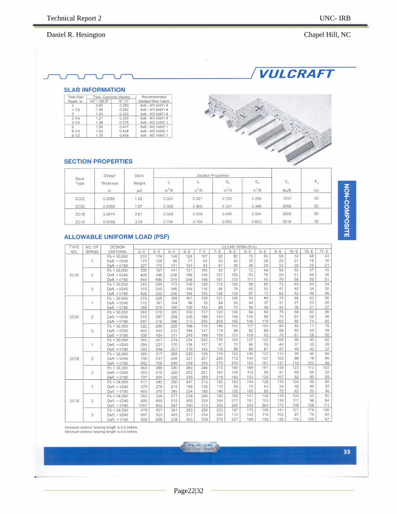
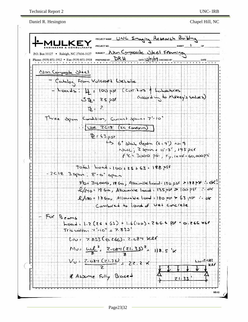
Concrete: 6” slab (2” deck with 4” of concrete) Dead (self weight): 75 psf f’c = 3000 psi Live: 100 psf Steel: fy = 50,000 psi Superimposed: 25 psf Reinfrocement: fy = 60,000 psi Metal Deck: 2C18 – 3 span Description
This non-composite steel system was designed using a typical interior bay of 21’-4” by 31’-4” with beams spaced 7’-10” on center as in the original concrete framing system. With a 3-span condition the Vulcraft 2C18 non-composite deck is able to span 11’-7” during construction, which is greater than the 7’-10” spacing proposed for this framing layout. The 2”, 18 gauge deck is also topped with 4” of concrete for a 6” total slab depth. According to the allowable uniform load table in the Vulcraft manual, this system satisfies the system satisfies the bending stress and deflection limit design criteria given.
Calculations for this system were done using the AISC thirteenth edition Steel Construction Manual and RISA-3D. The steel manual was used to determine the sizes for the beams and girders and for efficiency of time RISA was used to determine the deflections of the girders to check that they did not exceed the deflection limits.
It was found that that the beams were controlled by the total load deflection of the system, and the girders were controlled by their moment capacity. The calculations supporting these findings can be found in Appendix B.
Advantages
There are several advantages to a steel frame system with a non-composite deck over a cast-in-place concrete slab. First, a steel frame system has a quicker erection time because it can arrive at the site prefabricated and there is no need for formwork. The lack of formwork will also reduce the cost of

Technical Report 2 UNC- IRB Daniel R. Hesington Chapel Hill, NC
Page13|32
labor, although this is not as big of deal in North Carolina because it not unionized like it is up North. Another advantage is that it is that decking is able to span 11’-7” during construction; therefore there will be no need for shoring. Finally, although a composite system was not looked at (and there are merits to a composite system), the non-composite system will also save money due to the absence of shear studs.
Disadvantages
The biggest disadvantage to this system in regards to the Imaging Research Building is that on the lower floors where there are a number of pieces of imaging equipment, the steel used would have to be stainless steel. This is due to the fact that the imaging equipment is magnetized and any ferrous material used can disrupt the magnetic field and ruin the equipment. Therefore using a steel frame system for the lower floor would be a large cost increase considering as of September 2009, the North American stainless steel price was 2945 US$/tonne compared to the carbon steel price of 680 US$/tonne.
Besides the cost increase for having to use stainless steel on the lower floors, there are several other disadvantages as well. Although probably not likely, one disadvantage could be possible floor vibrations. The reason that this is relatively unlikely though is that there is going to be a lot a heavy equipment used in the building that would act as a natural damper for the system. One problem though that would need to be addressed is the need for additional fire protection to obtain a 2 hour fire rating if a steel frame was used. Finally there is the issue with the existing lateral force resisting system of ordinary reinforced concrete shear walls. If the shear walls are to stay, special connections will need to be designed to frame the two materials together. Otherwise, a steel lateral system will have to be designed.
Feasibility
For the Imaging Research Building, I believe it is a tossup whether or not a steel floor framing system would be a feasible option or not. Perhaps, if a concrete base was used for the two subgrade floors and steel framing was used above, this could be an economical and reasonable option. Further investigation is needed to determine the validity of this argument.
Technical Report 2 UNC- IRB Daniel R. Hesington Chapel Hill, NC
Page14|32
Composite steel framing – Option #2
Material Properties: Loading:
Concrete: 6” slab (2” deck with 4” of concrete) Dead (self weight): 75 psf f’c = 3000 psi Live: 100 psf Steel: fy = 50,000 psi Superimposed: 25 psf Reinfrocement: fy = 60,000 psi Metal Deck: Vulcraft 2VL Description
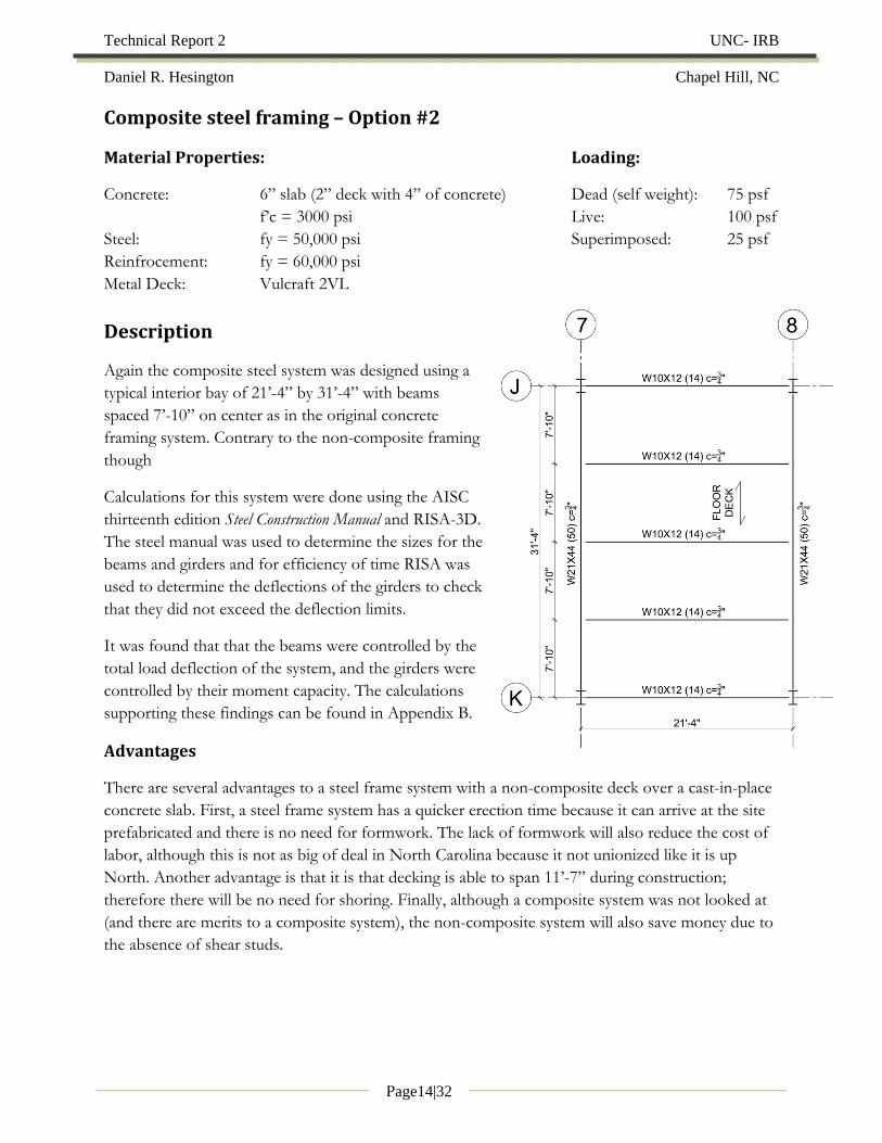
Again the composite steel system was designed using a typical interior bay of 21’-4” by 31’-4” with beams spaced 7’-10” on center as in the original concrete framing system. Contrary to the non-composite framing though
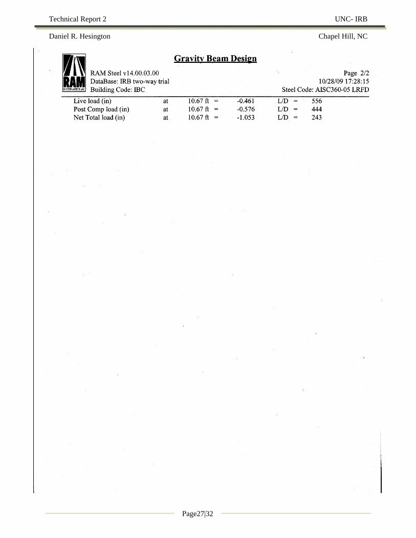
Calculations for this system were done using the AISC thirteenth edition Steel Construction Manual and RISA-3D. The steel manual was used to determine the sizes for the beams and girders and for efficiency of time RISA was used to determine the deflections of the girders to check that they did not exceed the deflection limits.
It was found that that the beams were controlled by the total load deflection of the system, and the girders were controlled by their moment capacity. The calculations supporting these findings can be found in Appendix B.
Advantages
There are several advantages to a steel frame system with a non-composite deck over a cast-in-place concrete slab. First, a steel frame system has a quicker erection time because it can arrive at the site prefabricated and there is no need for formwork. The lack of formwork will also reduce the cost of labor, although this is not as big of deal in North Carolina because it not unionized like it is up North. Another advantage is that it is that decking is able to span 11’-7” during construction; therefore there will be no need for shoring. Finally, although a composite system was not looked at (and there are merits to a composite system), the non-composite system will also save money due to the absence of shear studs.

Technical Report 2 UNC- IRB Daniel R. Hesington Chapel Hill, NC
Page15|32
Disadvantages
The biggest disadvantage to this system in regards to the Imaging Research Building is that on the lower floors where there are a number of pieces of imaging equipment, the steel used would have to be stainless steel. This is due to the fact that the imaging equipment is magnetized and any ferrous material used can disrupt the magnetic field and ruin the equipment. Therefore using a steel frame system for the lower floor would be a large cost increase considering as of September 2009, the North American stainless steel price was 2945 US$/tonne compared to the carbon steel price of 680 US$/tonne.
Besides the cost increase for having to use stainless steel on the lower floors, there are several other disadvantages as well. Although probably not likely, one disadvantage could be possible floor vibrations. The reason that this is relatively unlikely though is that there is going to be a lot a heavy equipment used in the building that would act as a natural damper for the system. One problem though that would need to be addressed is the need for additional fire protection to obtain a 2 hour fire rating if a steel frame was used. Finally there is the issue with the existing lateral force resisting system of ordinary reinforced concrete shear walls. If the shear walls are to stay, special connections will need to be designed to frame the two materials together. Otherwise, a steel lateral system will have to be designed.
Feasibility
For the Imaging Research Building, I believe it is a tossup whether or not a steel floor framing system would be a feasible option or not. Perhaps, if a concrete base was used for the two subgrade floors and steel framing was used above, this could be an economical and reasonable option. Further investigation is needed to determine the validity of this argument.

Technical Report 2 UNC- IRB Daniel R. Hesington Chapel Hill, NC
Page16|32
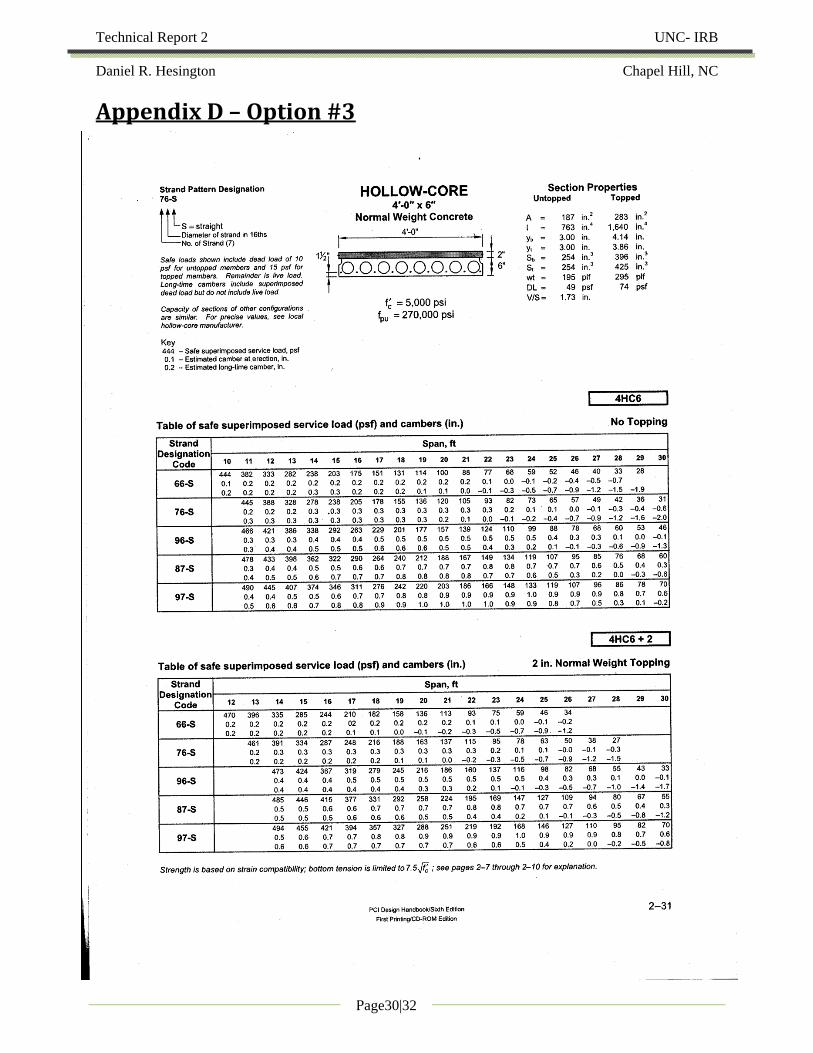
Hollow core precast on steel beams – Option #3
Material Properties: Loading:
Concrete: 4’-0”x6” plank (NWC) Dead (self weight): 75 psf 20”x20” columns Live: 100 psf f’c = 5000 psi Superimposed: 25 psf Reinfrocement: fy = 60,000 psi Description
The hollow core precast concrete system can be used if there is a slight adjustment to all of the bays within the building. Because the precast panels come in 4’-0” wide sections, it seems logical to set the typical interior bay size to 32’x21’-4” as shown in figure ___. Of course, the other bays in the building will also have to be adjusted, but for all intensive purposes of this technical report just the 32’x21’-4” bay was examined.
Using the PCI Design Handbook, a 6” thick plank with 2” topping was chosen for this floor system. The span of 21’-4” was satisfied using 96-S strands within the hollow core panel. In other words, the panel will contain 9 strands a 6/16ths, and that the strands are straight (S). This floor system is capable of supporting a superimposed service load of 160 psf which is greater than 140 psf which calculated using the 100 psf live load, the 25 psf superimposed dead load, and 15 psf for the 2” topping according to the PCI Design Handbook.
As seen in figure ___, the steel sections that the precast hollow core planks will frame into are W24x76’s. This was determined using the AISC 13th edition Steel Construction Manual. The calculations supporting these sizes can be found in Appendix ___.
Advantages
There are a number of advantages to the hollow core precast plank system. First, the system is durable and it is a low maintenance assembly. Not only that, but it takes little time to construct because no curing time is needed. Therefore, construction can be completed quicker than with a

Technical Report 2 UNC- IRB Daniel R. Hesington Chapel Hill, NC
Page17|32
cast-in-place slab which could allow for earlier occupancy. Besides that added construction benefits it also attenuates noise and is a recognized as a LEED rated system.
Disadvantages
In regards to the Imaging Research Building, there are also some disadvantages to using the hollow core precast floor system. The most glaring one would be that the bay sizes would have to be adjusted to accommodate the width of the planks. In turn, this would result in an increase in building footprint that may or may not be acceptable.
Also, again a steel framing system would be used which adds the factor of vibrations. It is unknown at this time the vibration that is associated with this system. Another disadvantage is the added depth to the framing system. Currently, the maximum depth for the bay anaylzed is 30” at the girders. If precast planks were used instead the depth would increase to 31.9”. While this isn’t a large increase, it is still one that the other trades on the project such as the MEP would have to contend with when trying to design their systems.
Again, as with non-composite floor system there is also a concern with the connections required at the concrete shear walls if that was to remain as the lateral force resisting system. Unless another lateral system was used, these connections could be more time consuming and costly.
Feasibility
This floor system does not seem like a candidate for further investigation. The disadvantages to it outweigh the benefits for its use in the Imaging Research Building.

Technical Report 2 UNC- IRB Daniel R. Hesington Chapel Hill, NC
Page18|32

Technical Report 2 UNC- IRB Daniel R. Hesington Chapel Hill, NC
Page19|32
Conclusions
After reviewing the advantages and disadvantages of each of the four floor systems is appears that the two-way cast in place slab, and the non-composite steel framing are the most feasible alternate floor framing systems. Both are options that have enough positives to be reviewed further. However, since the non-composite steel framing seems to be a viable option it is decided that a composite steel frame system should also be investigated in the future.
First, there are several benefits to the two-way flat slab that make it a feasible option as an alternate floor system. There is no additional fireproofing required and the layout of the building does not need to change.
Technical Report 2 UNC- IRB Daniel R. Hesington Chapel Hill, NC
Page20|32
Appendix A Gravity Load Calculations

Technical Report 2 UNC- IRB Daniel R. Hesington Chapel Hill, NC
Page21|32
Appendix B Option #1
Technical Report 2 UNC- IRB Daniel R. Hesington Chapel Hill, NC
Page22|32
Technical Report 2 UNC- IRB Daniel R. Hesington Chapel Hill, NC
Page23|32

Technical Report 2 UNC- IRB Daniel R. Hesington Chapel Hill, NC
Page24|32

Technical Report 2 UNC- IRB Daniel R. Hesington Chapel Hill, NC
Page25|32

Technical Report 2 UNC- IRB Daniel R. Hesington Chapel Hill, NC
Page26|32
Appendix C – Option #2
Technical Report 2 UNC- IRB Daniel R. Hesington Chapel Hill, NC
Page27|32

Technical Report 2 UNC- IRB Daniel R. Hesington Chapel Hill, NC
Page28|32

Technical Report 2 UNC- IRB Daniel R. Hesington Chapel Hill, NC
Page29|32
Technical Report 2 UNC- IRB Daniel R. Hesington Chapel Hill, NC
Page30|32
Appendix D – Option #3

Technical Report 2 UNC- IRB Daniel R. Hesington Chapel Hill, NC
Page31|32

Technical Report 2 UNC- IRB Daniel R. Hesington Chapel Hill, NC
Page32|32
Related Documents