i A PROJECT REPORT ON “Design and Fabrication of Semi-Automatic System for Welding Hydraulic Cylinder” Submitted by Syed Zaid Karim (11ME59) Mukri Yasir Ashraf (12ME74) Syed Mohd. Talha Jafri Asrar Husain (11ME58) Dakhwe Akib Nisar (12ME76) In partial fulfillment for the award of the Degree Of BACHELOR OF ENGINEERING IN MECHANICAL ENGINEERING UNDER THE GUIDANCE Of Prof. Javed Kazi DEPARTMENT OF MECHANICAL ENGINEERING ANJUMAN-I-ISLAM KALSEKAR TECHNICAL CAMPUS NEW PANVEL, NAVI MUMBAI – 410206 UNIVERSITY OF MUMBAI ACADEMIC YEAR 2014-2015

Welcome message from author
This document is posted to help you gain knowledge. Please leave a comment to let me know what you think about it! Share it to your friends and learn new things together.
Transcript
i
A PROJECT REPORT
ON
“Design and Fabrication of Semi-Automatic System for Welding
Hydraulic Cylinder”
Submitted by
Syed Zaid Karim (11ME59)
Mukri Yasir Ashraf (12ME74)
Syed Mohd. Talha Jafri Asrar Husain (11ME58)
Dakhwe Akib Nisar (12ME76)
In partial fulfillment for the award of the Degree
Of
BACHELOR OF ENGINEERING
IN
MECHANICAL ENGINEERING
UNDER THE GUIDANCE
Of
Prof. Javed Kazi
DEPARTMENT OF MECHANICAL ENGINEERING
ANJUMAN-I-ISLAM
KALSEKAR TECHNICAL CAMPUS NEW PANVEL,
NAVI MUMBAI – 410206
UNIVERSITY OF MUMBAI
ACADEMIC YEAR 2014-2015

ii
ANJUMAN-I-ISLAM
KALSEKAR TECHNICAL CAMPUS NEW PANVEL
(Approved by AICTE, recg. By Maharashtra Govt. DTE,
Affiliated to Mumbai University)
PLOT #2&3, SECTOR 16, NEAR THANA NAKA, KHANDAGAON, NEW PANVEL,NAVI MUMBAI-410206, Tel.: +91 22 27481247/48 * Website: www.aiktc.org
CERTIFICATE
This is to certify that the project entitled
“Design and Fabrication of Semi-Automatic System for Welding Hydraulic
Cylinder”
Submitted by
Syed Zaid (11ME59)
Mukri Yasir (12ME74)
Syed Mohd. Talha Jafri (11ME58)
Dakhwe Akib Nisar (12ME75)
To the Kalsekar Technical Campus, New Panvel is a record of bonafide work carried
out by him under our supervision and guidance, for partial fulfillment of the requirements for
the award of the Degree of Bachelor of Engineering in Mechanical Engineering as prescribed
by University Of Mumbai, is approved.
Project co-guide Internal Examinar External Examiner
( Prof. Javed Kazi) (Prof. Zoya Rizvi )
Head of Department Principal
(Prof. Zakir Ansari) (Dr. Abdul Razzak Honnutagi)

iii
ANJUMAN-I-ISLAM
KALSEKAR TECHNICAL CAMPUS NEW PANVEL
(Approved by AICTE, recg. By Maharashtra Govt. DTE,
Affiliated to Mumbai University)
PLOT #2&3, SECTOR 16, NEAR THANA NAKA, KHANDAGAON, NEW PANVEL,NAVI MUMBAI-410206, Tel.: +91 22 27481247/48 * Website: www.aiktc.org
APPROVAL OF DISSERTATION
This is to certify that the thesis entitled
“Design and Fabrication of Semi-Automatic System for Welding Hydraulic
Cylinder”
Submitted by
Syed Zaid (11ME59)
Mukri Yasir (12ME74)
Syed Mohd. Talha Jafri (11ME58)
Dakhwe Akib Nisar (12ME75)
In partial fulfillment of the requirements for the award of the Degree of Bachelor of
Engineering in Mechanical Engineering, as prescribed by University of Mumbai approved.
(Internal Examiner) (External Examiner)
Prof. Zoya Rizvi _________________
Date: 27/04/2015

iv
ACKNOWLEDGEMENT
After the completion of this work, we would like to give our sincere thanks to all
those who helped us to reach our goal. It’s a great pleasure and moment of immense
satisfaction for us to express my profound gratitude to our guide Prof. Javed Kazi whose
constant encouragement enabled us to work enthusiastically. His perpetual motivation,
patience and excellent expertise in discussion during progress of the project work have
benefited us to an extent, which is beyond expression.
We would also like to give our sincere thanks to Prof. Zakir Ansari, Head of
Department, Prof. Javed Kazi, Project Co-Guide and Prof. Shaikh M. Javed, Project co-
ordinator from Department of Mechanical Engineering, Kalsekar Technical Campus, New
Panvel, for their guidance, encouragement and support during a project.
I take this opportunity to give sincere thanks to Mr. Ramesh Havannavar, Owner in
“Bell Fluidtechnics Private Limited”, for all the help rendered during the course of this
work and their support, motivation, guidance and appreciation.
I am thankful to Dr. Abdul Razzak Honnutagi, Kalsekar Technical Campus New
Panvel, for providing an outstanding academic environment, also for providing the adequate
facilities.
Last but not the least I would also like to thank all the staffs of Kalsekar Technical
Campus (Mechanical Engineering Department) for their valuable guidance with their interest
and valuable suggestions brightened us.
Syed Zaid (11ME59)
Mukri Yasir (12ME74)
Syed Mohd. Talha Jafri (11ME58)
Dakhwe Akib Nisar (12ME75)

v
Declaration
I declare that this written submission represents my ideas in my own
words and where others' ideas or words have been included, I have
adequately cited and referenced the original sources. I also declare that I
have adhered to all principles of academic honesty and integrity and have
not misrepresented or fabricated or falsified any idea/data/fact/source in
my submission. I understand that any violation of the above will be cause
for disciplinary action by the Institute and can also evoke penal action
from the sources which have thus not been properly cited or from whom
proper permission has not been taken when needed.
Date: 27/04/2015
vi
Contents Chapter 1 Introduction 1
1.1 Company’s Introduction 2
1.1.1 Application of company’s product 2
1.2 Welding 2
1.2.1 MIG Welding 3
1.3 Hydraulic Cylinder 3
1.4 Geared Servo Motor or Servo Motor with Gearbox 5
Chapter 2 Review of Literature 6
Chapter 3 Report on Present Investigation and Work 10
3.1 Problem Definition 11
3.2 Methodology Adopted 12
3.2.1 Working Status (Our Work) 12
3.2.2 Design Using Hydraulic System 14
3.2.3 Design using Geared Servo Motor 28
Chapter 4 Result & Discussion 30
Chapter 5 Conclusion & Future Scope 32
5.1 Conclusion 33
5.2 Future Scope 33
Chapter 6 Literature Cited 34
6.1 Company Certificate 37
6.2 Publication 38

vii
List of Figures
Figure 1.1 MIG Welding 3
Figure 1.2 Hydraulic Cylinder 4
Figure 1.3 Geared Servo Motor 5
Figure 3.1 VEE block used by company 11
Figure 3.2 Flow ChaRT 12
Figure 3.3 Rollers 13
Figure 3.4 Electric Motor 14
Figure 3.5 Gear Motor 15
Figure 3.6 Solenoid Operated DC Valve 15
Figure 3.7 Hydraulic Motor 16
Figure 3.8 Manifold Assembly 17
Figure 3.9 Circuit Design in Festo 17
Figure 3.10 Simple Working Figure 18
Figure 3.11 Pressure at base 20
Figure 3.12 Pressure on all faces 20
Figure 3.13 Gravity 21
Figure 3.14 Von Mises Stress 23
Figure 3.15 Maximum Displacement 23
Figure 3.16 Displacement in X-direction 24
Figure 3.17 Displacement in Y-direction 24
Figure 3.18 Displacement in Z-direction 25
Figure 3.19 Design of Fixture 26
Figure 3.20 Design of Fixture 27
Figure 3.21 Gear Motor System 28

viii
List of Tables
Table 3.1 Physical Property 19
Table 3.2Material Properties 19
Table 3. 3Result Summary 21
Table 3.4 Chemical Composition of C40 25
Table 3.5 Costing of Hydraulic System 27
Table 3.6 Costing of Gear Motor System 29
ix
Abstract
In this era of automation technology, industries have put a very high demand on
fast and reliable methods. Hydraulic system is one of the latest technologies in
industrial field. Hydraulic cylinder is an important part of hydraulic system
which makes it more important as industrial product.
Fixtures are used to hold the work piece and serve as one of the most important
facility of mass production system. Welding fixtures are normally designed to
hold and support the various components (work pieces) to be welded. It is
necessary to support them in a proper location which is capable of preventing
distortions in work pieces during welding.
We will be evaluating the existing system of processing hydraulic cylinder in
the plant. The current system uses manually rotation of the cylinder. Hence, we
will be designing a welding fixture which will be holding the hydraulic cylinder
in one position and welding can be done at the required area. The present report
discusses the various methods and effective system which is adopted to increase
the productivity of the plant.

1
Chapter 1 Introduction

2
1.1 Company’s Introduction
We are working for “BELL FLUIDTECHNICS PRIVATE LIMITED” that deals with
hydraulic products. Established in the year 1996, The Company manufactures supplies
and exports of Valves, Oil Coolers, Linear Transducers and Pumps. The company has
their branches in Mumbai and Bangalore. The plant that we are working in manufactures
Hydraulic power pack, hydraulic cylinder, lift valves and hydraulic accessories like return
line filter, drain plug etc.
1.1.1 Application of company’s product
i. HYDRAULIC CYLINDERS which are widely used in various applications such as
construction equipment, manufacturing machines. It is used to provide unidirectional
force. They are cost effective & reliable.
ii. RETURN LINE FILTER is used in return line/tank line prior to tank port. Is used to
protect foreign/dirt material entering the oil tank and protecting the system.
iii. DRAIN PLUG is made of Carbon steel and precision machined. Used in hydraulic oil
tank to plug the drain port.
iv. HYDRAULIC JACK with power pack is used to lift petrol truck and heavy vehicle.
1.2 Welding
Welding is a fabrication process in every industry large or small. It is a principal means of
fabricating and repairing metal products.
The process is efficient, economical and dependable as a means of joining metals.
The process finds its applications in air, underwater and space.
Why welding is used- Because it is,
i. Suitable for thickness ranging from fractions of a millimeter to a third of a meter.
ii. Versatile, being applicable to a wide range of component shapes and sizes.
3
1.2.1 MIG Welding
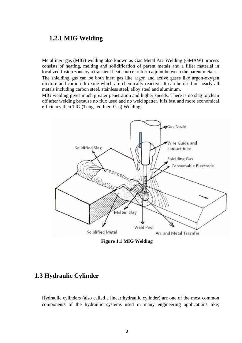
Metal inert gas (MIG) welding also known as Gas Metal Arc Welding (GMAW) process
consists of heating, melting and solidification of parent metals and a filler material in
localized fusion zone by a transient heat source to form a joint between the parent metals.
The shielding gas can be both inert gas like argon and active gases like argon-oxygen
mixture and carbon-di-oxide which are chemically reactive. It can be used on nearly all
metals including carbon steel, stainless steel, alloy steel and aluminum.
MIG welding gives much greater penetration and higher speeds. There is no slag to clean
off after welding because no flux used and no weld spatter. It is fast and more economical
efficiency then TIG (Tungsten Inert Gas) Welding.
Figure 1.1 MIG Welding
1.3 Hydraulic Cylinder
Hydraulic cylinders (also called a linear hydraulic cylinder) are one of the most common
components of the hydraulic systems used in many engineering applications like;
4
automatic manufacturing and montage lines, heavy construction equipments, control
systems, sensitive measurement and test systems.
They are used for producing linear motion in the hydraulic systems and they convert
hydraulic energy to mechanical energy.
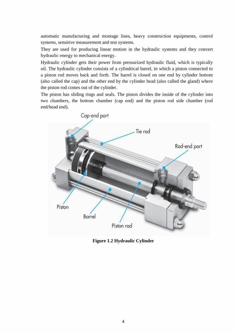
Hydraulic cylinder gets their power from pressurized hydraulic fluid, which is typically
oil. The hydraulic cylinder consists of a cylindrical barrel, in which a piston connected to
a piston rod moves back and forth. The barrel is closed on one end by cylinder bottom
(also called the cap) and the other end by the cylinder head (also called the gland) where
the piston rod comes out of the cylinder.
The piston has sliding rings and seals. The piston divides the inside of the cylinder into
two chambers, the bottom chamber (cap end) and the piston rod side chamber (rod
end/head end).
Figure 1.2 Hydraulic Cylinder
5
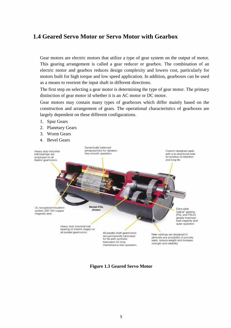
1.4 Geared Servo Motor or Servo Motor with Gearbox
Gear motors are electric motors that utilize a type of gear system on the output of motor.
This gearing arrangement is called a gear reducer or gearbox. The combination of an
electric motor and gearbox reduces design complexity and lowers cost, particularly for
motors built for high torque and low speed application. In addition, gearboxes can be used
as a means to reorient the input shaft in different directions.
The first step on selecting a gear motor is determining the type of gear motor. The primary
distinction of gear motor id whether it is an AC motor or DC motor.
Gear motors may contain many types of gearboxes which differ mainly based on the
construction and arrangement of gears. The operational characteristics of gearboxes are
largely dependent on these different configurations.
1. Spur Gears
2. Planetary Gears
3. Worm Gears
4. Bevel Gears
Figure 1.3 Geared Servo Motor

6
Chapter 2 Review of Literature

7
Bhargav C. Patel, Jaivesh Gandhi (2013) [13]
in their research paper “Optimizing and analysis
of parameter for pipe welding: A literature review” emphasis on the study of the effect of
different input parameter of TIG and MIG welding on the weld quality. They studied the
effect of various welding parameter by conducting different experiments.
As we know the most popular method for welding pipe is the shielded metal-arc process;
however, gas shielded arc methods have made big inroads as a result of new advances in
welding technology.
“SAFETY CONSIDERATIONS IN A WELDING PROCESS: A REVIEW” by Kapil Singh,
Ankush Anand (2013)[4]
aimed at highlighting the safety aspects in a welding process. In this
research article, following aspects of welding had been considered: (a) HAZARDS IN
WELDING. (b) SAFETY ASPECTS. (c)RISK ASSESMENT. It will help system designers,
industrialists and welding professionals to overcome the issues being faced by the present day
welders in a manufacturing environment, thus ensuring greater safety.
M. Rama Narasimha Reddy et. al in their paper “Design of Hydraulic Power Pack for Vertical
Turret Lathe”(2014) [5]
have designed hydraulic power pack to obtain various motions of
Vertical Turret Lathe. Also clamping and unclamping is done using hydraulic system. Their
design has made automation possible for all types of movements. In addition, speeds and
forces can be easily controlled in this system. Special emphasis is made on design of power
pack in which the elements, maintenance aspects and trouble-shooting methods is dealt with.
Gautam Kocher, Sandeep Kumar, Gurcharan Singh(2012)[6]
studied on welding speed as
process variable while arc voltage, welding current, wire feed rate distance between the
nozzle and the plates are fixed in this experiment. The effect of weld speed on the weld bead
profile is been discussed with the effect of weld speed on the fusion angle and wetting angle.
The effect of weld speed on the weld bead dilution i.e. penetration area and reinforcement
were area also discussed.
“Numerical strength and fatigue analysis in application to hydraulic cylinders” by W.
Torbacki (2007) [11]
discussed about the strength and fatigue limit analysis applied to piston
type hydraulic cylinders. Design analysis has been done via Finite Element Method. They also
presented fatigue graph for different values of operating mean pressure and stress
concentration factor.
Satyaduttsinh P. Chavda, Tushar M. Patel et al presented the technique used for obtaining
optimal process parameters with the use of experimental data. The aim of their paper “A
Review on Parametric Optimization of MIG Welding for Medium Carbon Steel Using FEA-
DOE Hybrid Modeling”(2013) [3]
is to review the of optimizing process parameters of MIG
welding process and compare the experimental result with FEA for optimizing parameter.
Shailesh S.Pachbhai, Laukik P.Raut (2014)[7]
researched in his paper “A REVIEW ON
DESIGN OF FIXTURES” on various types of fixture and clamping process which can be
used for locating various shapes of object. It also showed to detail procedure for design of the
fixture including the parameters to be considered before designing the fixture. Also have
8
studied on how the design of fixture can improve the production rate and reliability. It has
also reduced the time of engagement and disengagement time of setting of the work piece.
“Precision Planetary Servo Gearheads” by G.G. Antony, Neugart, A. Pantelides [16]
et al
studied the planetary (epicyclical gear systems) for “servo applications” (applications using
servo motors) and the parameters influencing the positioning accuracy repeatability of a
planetary servo gear. And also introduce a simple and reliable method of determining the
required gearbox torque rating for a selected servo motor/gearbox application.
“Enhancement of the Performance of Hydraulic Power Pack by Increasing Heat Dissipation”
(2014) [8]
reviewed the heating of hydraulic oil and the inefficiencies results in loss of input
power. M.L.R. Chaitanya Lahari, DR.B.SRINIVASA REDDY made an attempt to reduce the
heating of the oil by changing the material of the tank and providing fins. Finally the
improvement of efficiency of power pack by reducing the heat losses has been studied and
analyzed.
“Analysis and Failure Improvement of Shaft of Gear Motor in CRM Shop” by D. K. Padhal,
D. B. Meshram (2013)[2]
studied the frequent failure analysis of output shaft of gear motor
used for cold rolling mill to drive the Pay-off Four-HI (Horizontally inserted). The analysis
has been done by calculation and then it is compared with the values in ANSYS software and
parameters than can increase shaft life have been discussed.
“FINITE ELEMENT MODEL TO PREDICT RESIDUAL STRESSES IN MIG WELDING”
by Harshal K. Chavan, Gunwant D. Shelake, M. S. Kadam (2012) [9]
researched on the
responses of single pass corner-joint of arc welding are evaluated through the finite element
software (ANSYS). They studied the effects of varying heat input, welding speed on the
thermo mechanical responses of the weldment after cooling down to room temperature. The
results were as follows:
a. As heat input changes, strain changes respectively.
b. As the heat input increases temperature generates in the plat increases and thus the
stress generated decreases.
c. The faster the welding speed is made, the less heat is absorbed by the base metal and
thus stresses induced decreases.
“DESIGN OF WELDING FIXTURES AND POSITIONERS” studied by Prof. S.N.Shinde et
al, (2014) [12]
, reviewed the construction & design feature for welding fixture and made
consideration of the following parameters: that is properly positioning of the work piece
which will help the welder to easily access the area to be weld and also reduces welder
fatigue. It also ensures safety to the welder. When a weldment is a cylindrical, it is eligible to
be supported when rotated. Small turning rolls idlers and jack stands with rollers can support
the cylinder during rotation. These do not help offset loads center of gravity away from the
center of the table out toward the edge of the table or further
Mohan B. Raut, S. N. Shelke(2014) [1]
in their paper “Optimization of Special Purpose
Rotational MIG Welding by Experimental and Taguchi Technique” presented the case study
to find the design optimization for special purpose MIG welding operation. This paper
presents the effect of welding parameters like welding current, welding voltage, welding

9
speed, gas flow rate, rotational speed of work piece, filler wire feed rate on MIG welding. An
Orthogonal Array, Signal to Noise (S/N) ratio and analysis of variance (ANOVA) are used to
find out the welding characteristics and optimization parameters. Finally the confirmations
tests have been carried out to compare the predicted values with the experimental values.
“Design of Modern Hydraulic Tank using Fluid Flow Simulation” in their paper presented the
development of industrial hydraulic tank. Lovrec (2012) [14]
et al studied several variations of
new hydraulic tank designs compared with industrial hydraulic tank. Further, to reduce oil
swirling and improve stability of oil flow, CFD simulation of oil flow inside hydraulic tank
were made. Also function and application of hydraulic tank along with the stream line result
is also discussed.
In the paper “A Review on Speed Control techniques of Single Phase Induction Motor”
various types of speed control methods for single phase induction motor are described. Atul
M. Gajare, Nitin R. Bhasme (2012) [15]
elaborates speed control by means of input parameters
like frequency. They used MOSFET as a switching element and concluded that the frequency
range is 16 to 57 Hz at constant voltage for changing the speed of induction motor.
“Design Study and Analysis of Water Hydraulic High Torque Low Speed Motor” by Sagar
Sonawane, Saurabh Pandharikar, R.M.Tayade (2014) [10]
studied High Torque Low Speed
(HTLS) Motor. Their work showed that hydraulic direct drives are more desirable than high
speed motors with mechanical multipliers. Analysis for variation of Torque, various losses,
various forces have been carried out. Mechanical, hydraulic and overall efficiency of the
motor design has been evaluated at various operating pressures and Speed-Torque
characteristics of the motor have been evaluated.

10
Chapter 3 Report on Present Investigation and Work
11
3.1 Problem Definition
We are currently working on one of the important product of the hydraulic system that is
hydraulic cylinder. The company manufactures the cylinder by welding one of its ends (THE
AREA OF OUR INTEREST) and the other end is sealed. The hydraulic fluid (Acantis HM
68) is filled in the cylinder when welding is done. After the fluid is filled the end other end is
sealed using head end cover.
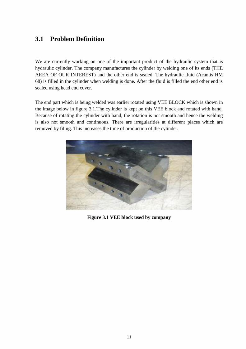
The end part which is being welded was earlier rotated using VEE BLOCK which is shown in
the image below in figure 3.1.The cylinder is kept on this VEE block and rotated with hand.
Because of rotating the cylinder with hand, the rotation is not smooth and hence the welding
is also not smooth and continuous. There are irregularities at different places which are
removed by filing. This increases the time of production of the cylinder.
Figure 3.1 VEE block used by company

12
3.2 Methodology Adopted
We have adopted the procedure as shown in the flow chart.
Figure 3.2 Flow ChaRT
3.2.1 Working Status (Our Work)
FIRST STAGE
In the initial part, we have provided a tool named as ROLLERS which is shown in the image.
Since, the cylinder is now rotating on rollers. It has pure rolling action and the cylinder is
rotated easily and smoothly.

13
Figure 3.3 Rollers
From our survey we have found three ways to rotate the cylinder.
i. Rotating the cylinder using a hand wheel i.e. manual rotation.
ii. Rotating the fixture using electric motor.
iii. Rotating the fixture using hydraulic motor.
iv. Rotating the fixture using geared motor.
Since the company wants an automation system to rotate the cylinder. Our first option was
eliminated.
From market search, we came to know that the minimum available electric motor speed is
1440 rpm. So to reduce and bring the speed to 5 rpm needs a very high gear ratio which is
288:1. This could not be achieved in single stage gear box. It needs at least two stage gear box
which will make the system bulky and costly. Moreover, maintenance of such a system is
high. Hence, the second option was eliminated.
The third option was using hydraulic motor. The system is costly but the company itself
produces the components. So the third option was suitable for the company and desired speed
can be easily achieved using this system.
The fourth option is using geared motors. These motors produce high torque at low speed
which is our motto to be achieved.
So both the last option can be fulfill our requirement. Therefore, we have planned and design
both the possible options which can resolve our problem. Further methodology discusses the
HYDRAULIC and GEAR MOTOR design along with costing.

14
3.2.2 Design Using Hydraulic System
A hydraulic system is a drive or transmission system that uses pressurized hydraulic fluid to
power hydraulic machinery.
A hydraulic system consists of three main parts:
a. The generator (e.g. a hydraulic pump), driven by an electric motor
b. Valves, filters, piping etc. (to guide and control the system)
c. The actuator (e.g. a hydraulic motor) to drive the machinery.
Components require in a hydraulic drive system
The following are the components require in a hydraulic system drive:
i. Electric motor:
An electric motor is an electrical machine that converts electrical energy into
mechanical energy. Electric motors are used to produce linear or rotary force.
Figure 3.4 Electric Motor
ii. Hydraulic Pump:
A hydraulic pump is a mechanical source of power that converts mechanical power
into hydraulic energy. When a hydraulic pump operates, it creates a vaccum at the
pump inlet, which forces liquid from the reservoir into the inlet line to the pump and
by mechanical action delivers this liquid to the pump outlet and forces it into the
hydraulic system.
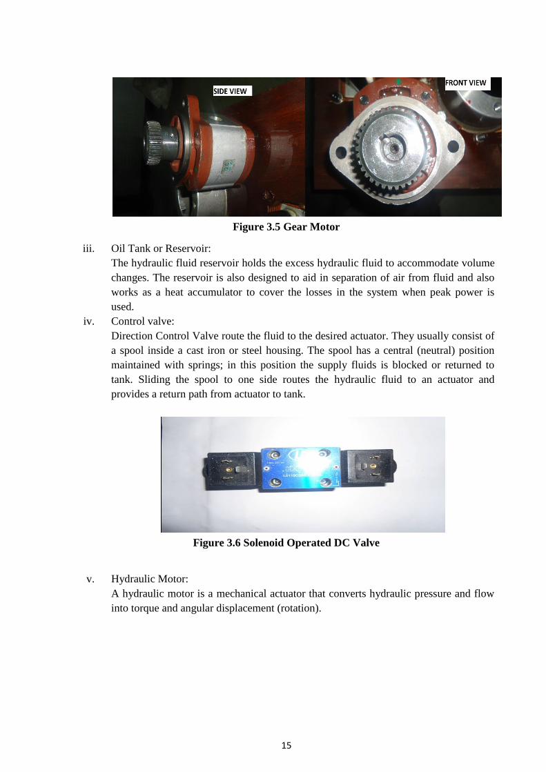
15
Figure 3.5 Gear Motor
iii. Oil Tank or Reservoir:
The hydraulic fluid reservoir holds the excess hydraulic fluid to accommodate volume
changes. The reservoir is also designed to aid in separation of air from fluid and also
works as a heat accumulator to cover the losses in the system when peak power is
used.
iv. Control valve:
Direction Control Valve route the fluid to the desired actuator. They usually consist of
a spool inside a cast iron or steel housing. The spool has a central (neutral) position
maintained with springs; in this position the supply fluids is blocked or returned to
tank. Sliding the spool to one side routes the hydraulic fluid to an actuator and
provides a return path from actuator to tank.
Figure 3.6 Solenoid Operated DC Valve
v. Hydraulic Motor:
A hydraulic motor is a mechanical actuator that converts hydraulic pressure and flow
into torque and angular displacement (rotation).

16
Figure 3.7 Hydraulic Motor
vi. Hydraulic fluid:
Hydraulic fluid is the life of the hydraulic circuit. It is usually petroleum oil with
various additives. The major function of hydraulic fluid is to provide energy
transmission through the system which enables work and motion to be accomplished.
Hydraulic fluids are responsible for lubrication, heat transfer and contamination
control.
vii. Tubes, pipes and hoses:
Hydraulic Tubes are seamless steel precision pipes, specially manufactured for
hydraulics. The tubes are interconnected by different types of flanges, welding
cones/nipples and by cut-rings.
Hydraulic pipe is used in case standard tubes are not available. Generally these are
used for low pressure. They can be connected by threaded connections, but usually by
welds.
Hydraulic Hose is graded by pressure and temperature, fluid compatibility. Hoses are
used when pipes or tubes cannot be used, usually to provide flexibility for machine
operation and maintenance. The hose is built up with rubber and steel layers.
viii. Filters:
Filters are an important part of hydraulic systems. Metal particles are continuously
produced by mechanical components and need to be removed along with other
components.
ix. Hydraulic Manifold:
A hydraulic manifold is a manifold that regulates fluid flow from between pumps and
actuators and other components in a hydraulic system. It is like a switchboard in an
electrical circuit because it lets the operator control how much fluid flows between
which components of hydraulic system.

17
Figure 3.8 Manifold Assembly
Circuit diagram of hydraulic motor system
The circuit of the system is designed in FESTO software
Figure 3.9 Circuit Design in Festo
Working of the Hydraulic System
A simple working diagram of the system is shown in the figure below. Pump-inlet and motor
return (via the directional valve) are connected to the hydraulic tank. The flow is returned to
tank through the control valve’s open center; that is, when the control valve is centered.
Otherwise, if the control valve is actuated it routes fluid to and from an actuator tank. The
fluid’s pressure will rise to meet any resistance, since the pump has a constant output. If the
pressure rises too high, fluid returns to tank through a pressure relief valve.
18
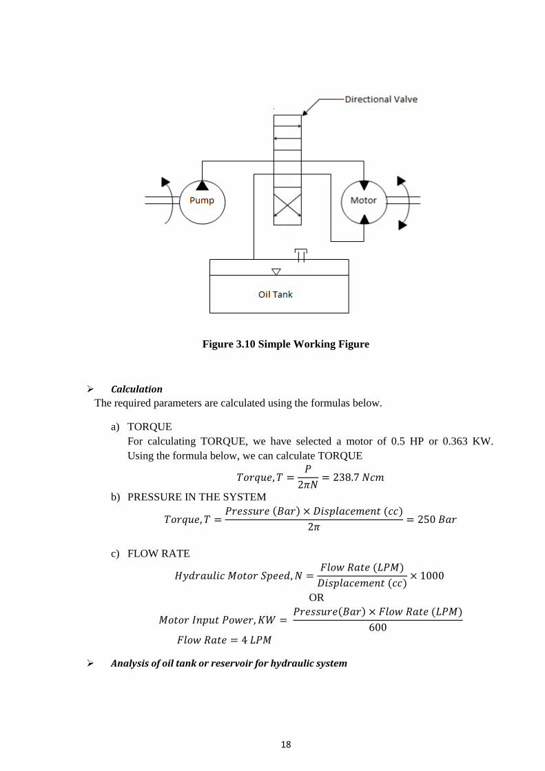
Figure 3.10 Simple Working Figure
Calculation
The required parameters are calculated using the formulas below.
a) TORQUE
For calculating TORQUE, we have selected a motor of 0.5 HP or 0.363 KW.
Using the formula below, we can calculate TORQUE
𝑇𝑜𝑟𝑞𝑢𝑒, 𝑇 =𝑃
2𝜋𝑁= 238.7 𝑁𝑐𝑚
b) PRESSURE IN THE SYSTEM
𝑇𝑜𝑟𝑞𝑢𝑒, 𝑇 =𝑃𝑟𝑒𝑠𝑠𝑢𝑟𝑒 (𝐵𝑎𝑟) × 𝐷𝑖𝑠𝑝𝑙𝑎𝑐𝑒𝑚𝑒𝑛𝑡 (𝑐𝑐)
2𝜋= 250 𝐵𝑎𝑟
c) FLOW RATE
𝐻𝑦𝑑𝑟𝑎𝑢𝑙𝑖𝑐 𝑀𝑜𝑡𝑜𝑟 𝑆𝑝𝑒𝑒𝑑, 𝑁 =𝐹𝑙𝑜𝑤 𝑅𝑎𝑡𝑒 (𝐿𝑃𝑀)
𝐷𝑖𝑠𝑝𝑙𝑎𝑐𝑒𝑚𝑒𝑛𝑡 (𝑐𝑐)× 1000
OR
𝑀𝑜𝑡𝑜𝑟 𝐼𝑛𝑝𝑢𝑡 𝑃𝑜𝑤𝑒𝑟, 𝐾𝑊 = 𝑃𝑟𝑒𝑠𝑠𝑢𝑟𝑒(𝐵𝑎𝑟) × 𝐹𝑙𝑜𝑤 𝑅𝑎𝑡𝑒 (𝐿𝑃𝑀)
600
𝐹𝑙𝑜𝑤 𝑅𝑎𝑡𝑒 = 4 𝐿𝑃𝑀
Analysis of oil tank or reservoir for hydraulic system

19
Table 3.1 Physical Property
Mass 0.0892415 kg
Area 94521.2 mm^2
Volume 85429.3 mm^3
Center of Gravity
x=-12.0451 mm
y=58.3855 mm
z=30.2483 mm
Table 3.2Material Properties
Name Steel, Mild, Welded
General
Mass Density 7.85 g/cm^3
Yield Strength 207 MPa
Ultimate Tensile Strength 345 MPa
Stress
Young's Modulus 220 GPa
Poisson's Ratio 0.275 ul
Shear Modulus 86.2745 GPa
Part Name(s)
Base Plate
Face 1
Face 2
Face 3
Face 4
Operating conditions
i. Pressure:1
Load Type Pressure
Magnitude 1.145 A

20
Figure 3.11 Pressure at base
ii. Pressure 2
Load Type Pressure
Magnitude 1.145 A
Figure 3.12 Pressure on all faces

21
iii. Gravity
Load Type Gravity
Magnitude 9810.000 mm/s^2
Vector X 0.000 mm/s^2
Vector Y 0.000 mm/s^2
Vector Z -9810.000 mm/s^2
Figure 3.13 Gravity
Table 3. 3Result Summary
Name Minimum Maximum
Volume 85429.3 mm^3
Mass 0.659161 kg
Von Mises Stress 0.3343 MPa 3657.41 MPa
1st Principal Stress -409.496 MPa 5397.61 MPa
3rd Principal Stress -2255.8 MPa 1594.77 MPa
Displacement 0 mm 6.05604 mm

22
Safety Factor 0.0751898 ul 15 ul
Stress XX -1239.32 MPa 4686.94 MPa
Stress XY -1745.95 MPa 1701.45 MPa
Stress XZ -379.9 MPa 377.989 MPa
Stress YY -1274.08 MPa 2772.54 MPa
Stress YZ -452.035 MPa 454.614 MPa
Stress ZZ -1122.14 MPa 2253.29 MPa
X Displacement -0.300884 mm 0.299464 mm
Y Displacement -6.04882 mm 6.05592 mm
Z Displacement -0.101989 mm 0.0762954 mm
Equivalent Strain 0.00000129895 ul 0.0515152 ul
1st Principal Strain -0.00000767387 ul 0.0610757 ul
3rd Principal Strain -0.0304584 ul 0.0000840247 ul
Strain XX -0.0157792 ul 0.0463523 ul
Strain XY -0.0337027 ul 0.0328436 ul
Strain XZ -0.00528738 ul 0.00648141 ul
Strain YY -0.0154446 ul 0.0160174 ul
Strain YZ -0.00872579 ul 0.00877557 ul
Strain ZZ -0.00474342 ul 0.00956578 ul
Contact Pressure 0 MPa 2175.28 MPa
Contact Pressure X -1480.69 MPa 1530.46 MPa
Contact Pressure Y -1880.88 MPa 1844.21 MPa
Contact Pressure Z -557.026 MPa 622.779 MPa

23
Figures
a. Von Mises Stress
Figure 3.14 Von Mises Stress
b. Displacement
Figure 3.15 Maximum Displacement
24
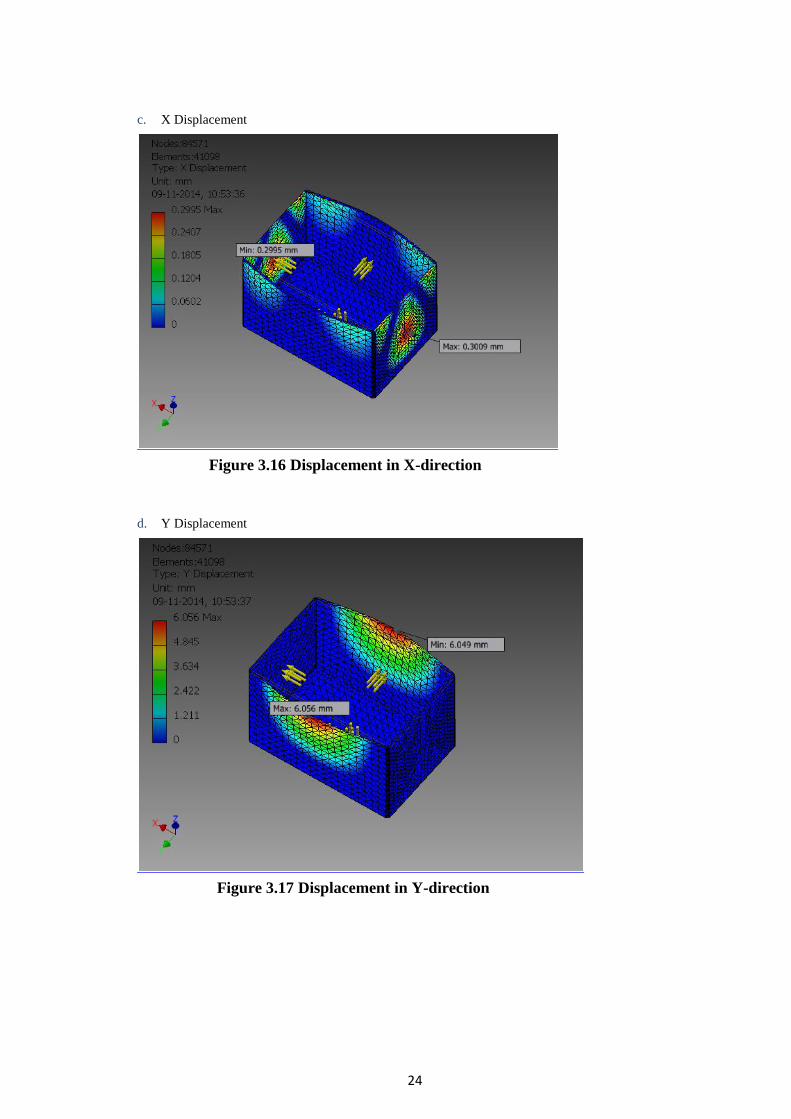
c. X Displacement
Figure 3.16 Displacement in X-direction
d. Y Displacement
Figure 3.17 Displacement in Y-direction
25
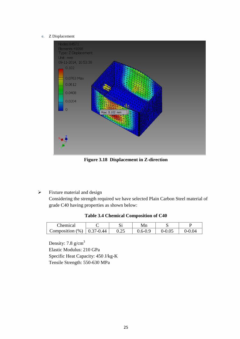
e. Z Displacement
Figure 3.18 Displacement in Z-direction
Fixture material and design
Considering the strength required we have selected Plain Carbon Steel material of
grade C40 having properties as shown below:
Table 3.4 Chemical Composition of C40
Chemical
Composition (%)
C Si Mn S P
0.37-0.44 0.25 0.6-0.9 0-0.05 0-0.04
Density: 7.8 g/cm3
Elastic Modulus: 210 GPa
Specific Heat Capacity: 450 J/kg-K
Tensile Strength: 550-630 MPa
26
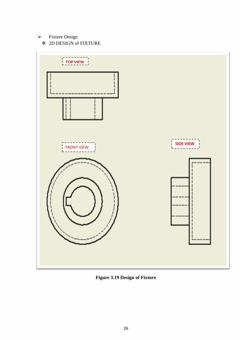
Fixture Design
2D DESIGN of FIXTURE
Figure 3.19 Design of Fixture
TOP VIEW
SIDE VIEW FRONT VIEW
27
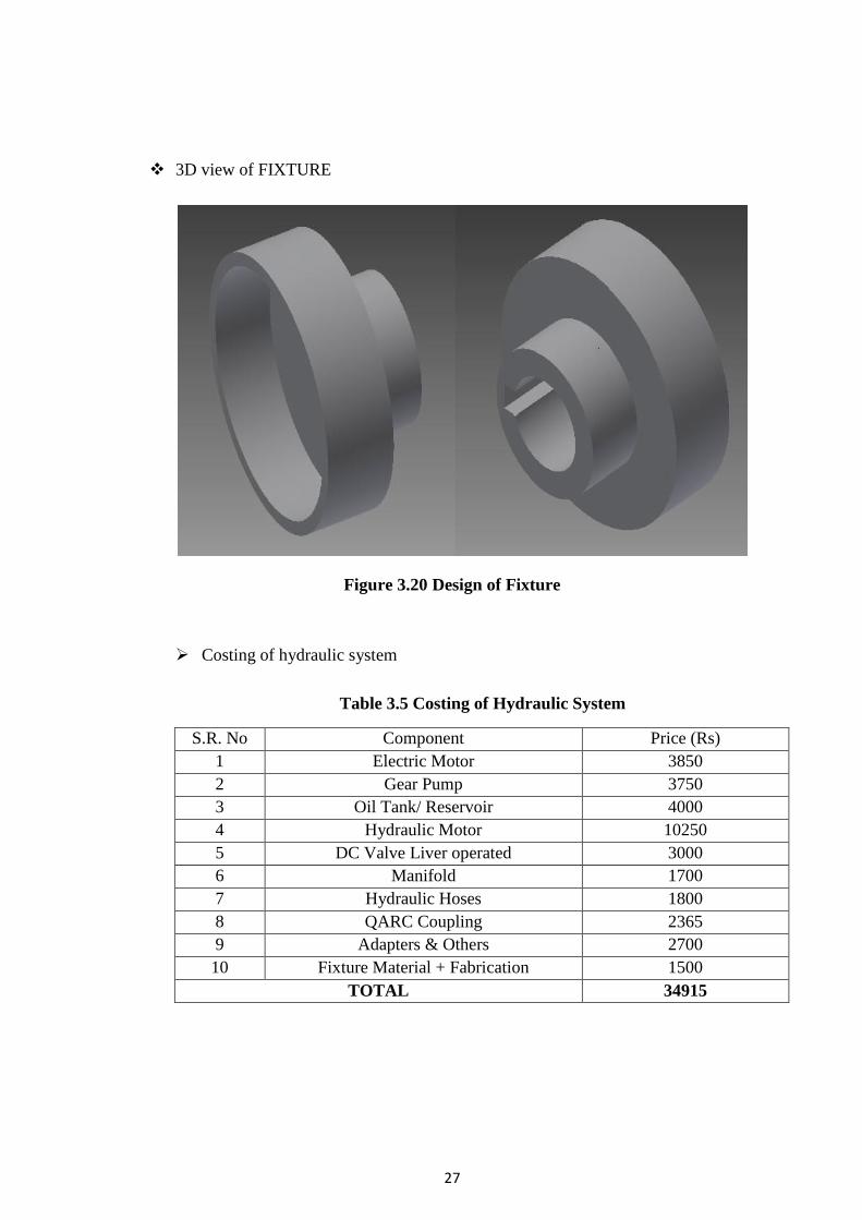
3D view of FIXTURE
Figure 3.20 Design of Fixture
Costing of hydraulic system
Table 3.5 Costing of Hydraulic System
S.R. No Component Price (Rs)
1 Electric Motor 3850
2 Gear Pump 3750
3 Oil Tank/ Reservoir 4000
4 Hydraulic Motor 10250
5 DC Valve Liver operated 3000
6 Manifold 1700
7 Hydraulic Hoses 1800
8 QARC Coupling 2365
9 Adapters & Others 2700
10 Fixture Material + Fabrication 1500
TOTAL 34915

28
3.2.3 Design using Geared Servo Motor
In this system we will be using a servo motor with gearbox installed in it. This motor provides
us with 10 RPM speed and we require a speed of 5 RPM. So to reduce the speed, we can use
pulley or gear attachment to get the required speed.
The parts that we require for this system:
a. PARALLEL SHAFT GEARMOTOR: Gear motors are electric motors that utilize a type
of gear system on the output of motor. This gearing arrangement is called a gear reducer
or gearbox. The motor is selected on the basis of input speed i.e. 10 RPM
b. FIXTURE: this fixture is designed to rotate cylinder of any diameter. We need a base
platform to support FOUR ROLLERS. The back rollers will be connected to shaft of the
pulley and pulley will run through the gear motor. The front two rollers will act as idle
roller and will help to rotate cylinder.
The working and design is discussed in the next part.
Design of geared motor system
Figure 3.21 Gear Motor System
Working
As shown in the design, the main component is the gear motor which will be driving
the pulley. This pulley is connected to another pulley via belt drive. The driven pulley
is smaller is size so as to reduce the speed from 10 RPM to 5 RPM. The ratios of the
diameters is 1:2

29
The shaft of the driven pulley is connected to one side of the two roller connected in
series. As the driven pulley moves, the rollers also move with the same speed as that
of the driven pulley. The other two wheels help to support the cylinder. When the
cylinder is kept vertically across the cylinder, the moving rollers rotate the cylinder in
the opposite direction as that of the roller. The idler roller rotates because of the
rotation of cylinder. This way cylinder of various sizes can be rotated using the same
system.
Further if this speed is fast for the welder then it can be reduce simply by changing the
idler pulley i.e. driven pulley. The diameter for idler pulley can be found out by using
the formula given below
𝐷𝑖𝑎𝑚𝑒𝑡𝑒𝑟 𝑜𝑓 𝐷𝑟𝑖𝑣𝑒𝑛 𝑝𝑢𝑙𝑙𝑒𝑦 (𝐷2)
𝐷𝑖𝑎𝑚𝑒𝑡𝑒𝑟 𝑜𝑓 𝐷𝑟𝑖𝑣𝑒𝑟 𝑝𝑢𝑙𝑙𝑒𝑦 (𝐷1)=
𝐼𝑛𝑝𝑢𝑡 𝑆𝑝𝑒𝑒𝑑 (𝑁1)
𝑂𝑢𝑡𝑝𝑢𝑡 𝑆𝑝𝑒𝑒𝑑 (𝑁2)
Where,
Diameter of driver pulley (D1) = 10 cm (we are fixing)
Input Speed (N1) = 10 RPM
Output Speed (N2) = 5, 4 …. 1 (depending upon the user)
Substituting these values we can find the diameter of required driven pulley.
The material used for fabrication of fixture is same as that of the hydraulic system.
Costing of gear motor system
Table 3.6 Costing of Gear Motor System
S.R. No COMPONENT PRICE (Rs)
1 Gear Motor 2500
2 Fixture material + Fabrication 1500
TOTAL 4000

30
Chapter 4 Result & Discussion

31
As per the methodology adopted, the systems are able to give us required output. But the
question arises which one is better than the other.
We will take a look at differentiating factors in both the systems and finally conclude with the
best suitable methods which will be cost effective and will help to improve the productivity
and efficiency of the company.
Table 4.1 Distinguish between Hydraulic & Gear Motor System
PARAMETERS HYDRAULIC SYSTEM GEARED MOTOR SYSTEM
Costing System is costly because requires
large number of components.
Relatively much cheaper.
Size Requires large space Compact Design
Change in SPEED To achieve change in speed fluid
pressure has to be controlled which
is difficult.
Speed change can be achieved
easily by changing the size of
IDLER pulley
Power High power generation capacity Less power compared to
hydraulic system
Maintenance High Low
Productivity 1 minute 10 seconds per cylinder 1 minute 10 seconds per cylinder
Fabrication Different diameters cylinder
requires special arrangement i.e.
BUSH PRESS FIT to be welded on
same fixture.
Single design i.e. ROLLERS can
be used to rotate cylinder of
varies diameters

32
Chapter 5 Conclusion & Future Scope

33
5.1 Conclusion
We have provided the industry with both the solutions i.e. using hydraulic and gear motor system.
Keeping the costing and difficulty in hydraulic system, the industry decided to go with the gear motor
system. Since, it is cost effective and is an easy system to be used.
Further from the maintenance point of view, the gear motor system can be easily maintained
compare to hydraulic system.
Implementation of any of the two systems will decrease the time of productivity of each cylinder and
increase the production of the industry. Earlier time required for production of one cylinder was 5
minutes 38 seconds, while with implementation time will be reduced to 1 minute and 10 seconds.
5.2 Future Scope
The system can be further automated by making the welding part of the system automated.
Moreover, the system can be analyzed using various techniques like ANOVA, VARIANCE and
REGRESSION etc. to study the change in output with change in input.

34
Chapter 6 Literature Cited

35
[1] Mohan B. Raut, S. N. Shelke, “Optimization of Special Purpose Rotational MIG Welding
by Experimental andTaguchi Technique”, International Journal of Innovative Technology and
Exploring Engineering (IJITEE), Volume-4Issue-6, November 2014, pp. 40-46
[2] D. K. Padhal, D. B. Meshram, “Analysis and Failure Improvement of Shaft of Gear Motor
in CRM Shop” International Journal of Engineering And Science, Vol.3, Issue 4 (July 2013),
PP 17-24
[3] Satyaduttsinh P. Chavda, Jayesh V. Desai, Tushar M. Patel, “A Review on Parametric
Optimization of MIG Welding for Medium Carbon Steel Using FEA-DOE Hybrid
Modeling”, International Journal for Scientific Research & Development (IJSRD), Vol. 1,
Issue 9, 2013, pp. 1785-1788
[4] Kapil Singh, Ankush Anand, “Safety Considerations In A Welding Process: A Review”,
International Journal of Innovative Research in Science, Engineering and Technology, Vol. 2,
Issue 2, February 2013, pp. 341-350
[5] M. Rama Narasimha Reddy, D. Sreenivasulu Reddy, P. Sundera, S. Madhusudhana,
“Design of Hydraulic Power Pack for Vertical Turret Lathe”, International Journal of
Research in Mechanical Engineering , Volume-2, Issue-2, March-April, 2014, pp. 13-22
[6] Gautam Kocher, Sandeep Kumar, Gurcharan Singh, “Experimental Effects”, International
Journal of Advanced Engineering Technology, Vol. III/ Issue II/April- June, 2012, pp. 158-
162
[7] Shailesh S.Pachbha1, Laukik P. Raut “A Review on Design of Fixtures”, International
Journal of Engineering Research and General Science Volume 2, Issue 2, Feb-Mar 2014, pp.
126-146
[8] M.L.R. Chaitanya Lahari, DR. B. SRINIVASA REDDY, International Journal of
Computational Engineering Research (IJCER), Vol. 04, Issue 8, August 2014, pp. 13-19
[9] Harshal K. Chavan, Gunwant D. Shelake, M. S. Kadam, “International Journal Of
Mechanical Engineering And Technology (IJMET)”, Volume 3, Issue 3, September -
December (2012), pp. 350-361
[10] Sagar Sonawane, Saurabh Pandharikar, R.M.Tayade, “Design Study and Analysis of
Water Hydraulic High Torque Low Speed Motor”, International Journal of Engineering
Development and Research (IJEDR), Volume 2, Issue 2, pp. 2903-2907
[11] W. Torbacki, “Numerical strength and fatigue analysis in application to hydraulic
cylinders”, Journal of Achievement in Material and Manufacturing Engineering, Vol. 25,
Issue 2, December 2007, pp. 65-68
36
[12] S.N.Shinde, Siddharth Kshirsagar, Aniruddha Patil, Tejas Parge, Ritesh Lomte “Design
of Welding Fixtures and Positioners”, International Journal of Engineering Research and
General Science Volume 2, Issue 5, August-September, 2014, pp. 681-689
[13] Bhargav C. Patel, Jaivesh Gandhi, “Optimizing and analysis of parameter for pipe
welding: A literature review”, International Journal of Engineering Research & Technology
(IJERT), Vol. 2 Issue 10, October – 2013, pp. 229-234
[14] Tic, Lovrec. “Design of Modern Hydraulic Tank using Fluid Flow Simulation”, 2012
[15] Atul M. Gajare, Nitin R. Bhasme, “A Review on Speed Control techniques of Single
Phase Induction Motor”, International Journal of Computer Technology and Electronics
Engineering (IJCTEE), Volume 2, Issue 5, October 2012, pp. 33-39
[16] G.G. Antony, Neugart, A. Pantelides, “Precision Planetary Servo Gearheads”, American
Gear Manufacturers Association

37
6.1 Company Certificate

38
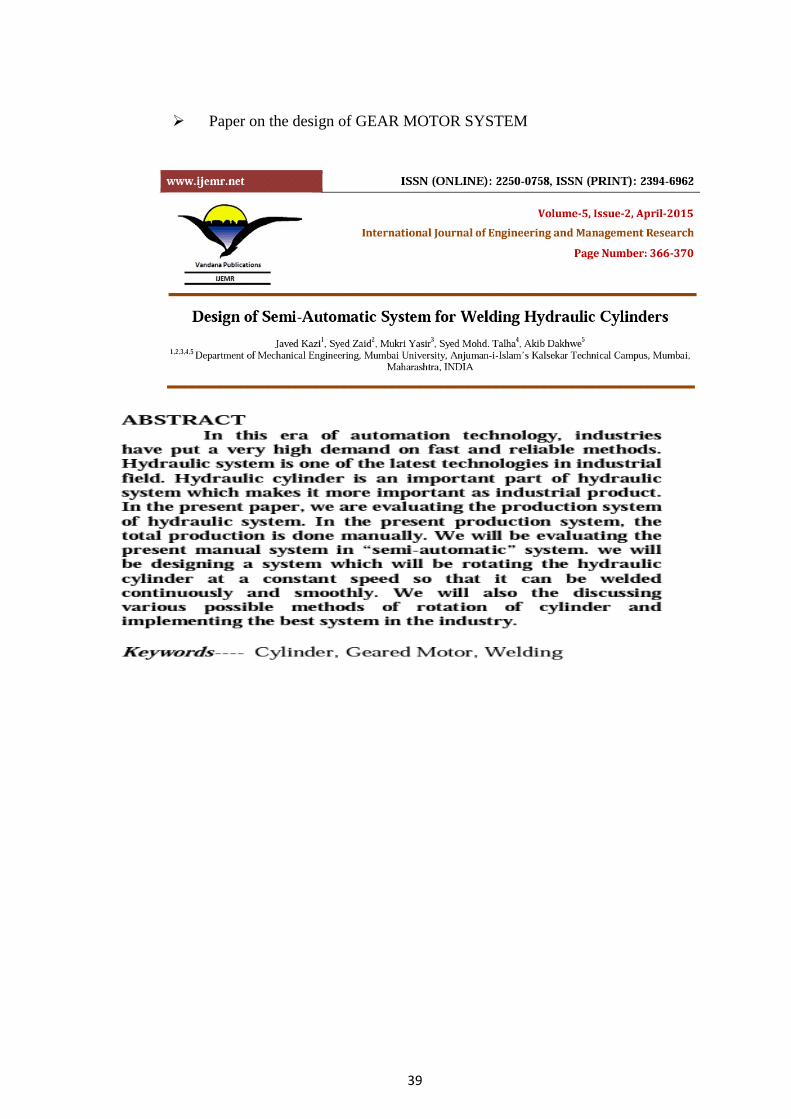
6.2 Publication
A study on the welding technique used in the industry
39
Paper on the design of GEAR MOTOR SYSTEM
Related Documents