- University of Nigeria Virtual Library Serial No Author 1 AGU, Marcel Ugwuoke Author 2 OKORO, Ogbonnaya .L. Author 3 Title Induction Motor Control Strategies: Past and Present. Keywords Induction Motor, Control Strategies, Adjustable Speed-Drives, Open Loop, Closed Loop. Description Induction Motor Control Strategies: Past and Present. Category Engineering Publisher The Pacific Journal of Science and Technology Publication Date May, 2005 Signature

Welcome message from author
This document is posted to help you gain knowledge. Please leave a comment to let me know what you think about it! Share it to your friends and learn new things together.
Transcript

-
University of Nigeria Virtual Library
Serial No
Author 1 AGU, Marcel Ugwuoke
Author 2 OKORO, Ogbonnaya .L. Author 3
Title Induction Motor Control Strategies: Past and Present.
Keywords
Induction Motor, Control Strategies, Adjustable Speed-Drives, Open Loop,
Closed Loop.
Description
Induction Motor Control Strategies: Past and Present.
Category
Engineering
Publisher
The Pacific Journal of Science and Technology
Publication Date May, 2005
Signature

Induction Motor Control Strategies: Past and Present.
Dr.-lng. Ogbonnaya I . 0koro' and Dr. M.U. Agu
Department of Electrical Engineering, University of Nigeria, Nsuklta, Enugu State. "E-mail: o ~ o k o r o ~ y a h o o . ~ ~ . ulc
ABSTRACT
The DC n~otor, the synchronous motor, and the' ~nduction motor have been the workhorses of industry for many years. The synchronous motor compares favorably with the induction motor due to its natural ability to supply reactive current as well as iis ability to eliminate rotor slip power loss. The control of DC motors is relatively s~rnple. In the case of the indwtion motor, advancements in semiconductor power electronics, micro-controllers, and micro- compulers have made it possible to reduce rninimslly the complexity inherent in its speed control.
This paper brings up to date the present and the past control strategies of the induction motor. The inherent problems encountered and the associated imprwements in the control and application of the induction motor are highlighted. The industrial applications of adjustable-speed induction motor drives are also presented.
(Kay words: indu40n motor, control strategies, adjustable speed-drives, open loop, closed loop).
INTRODUCTION
The DC motor, the synchronous motor, and the ~ntluction mo t~ r are the basic electric machines that have been in use in industry for nearly a century (Sen 1988). Due to sustained research efforts in drive technology, other types of electric machines, such as Brushless DC Machines, Permanent Masnet Machines, and Switched Reluctailce Machines, have recently become viable alternalives in many industrial applicaiions. The induction motor is superior to the DC motor with respect to smaller size, weight and motor inertia, maximum speed capability, efficiency, and lower cost (Murphy a;id Turnbull 1988; McDonald and Sen 1978; Nasar and Boldaa 1990; King 1963). However, the simplicity of control of the DC motor is much
Ihe Path Journal of Sdence and Tedrnobgy
r~t tpPI Iv .ywv,akamaiuf~ iver~~I~ .us lPJS:~~
higher because the induction motor inherently has a complex, non-linear, and highly interacting multi-variable control structure, whereas the separately excited DC motor has a decoupled control structure with independent control of flux and torque.
Comparable control performance of induction motor drives generally requires more convoluted control algorithms (implemented by fast real time signal processing) that control modern power semiconductor circuits, which drive the motor. However, the availability of adequate power serni-conductor devices, microelectronics, and microcomputers has sustained wide spread interest in variable speed induction motor drives and has consequently opened new possibilities in the control of induction motors.
Conventionally, electric motors were controlled manually (Ramamoorty and Arunachalam 1978; Sen and Ma 1975). Resistance control of DC motors and variac control of induction motors are typical examples. Electronic control started with the advent of gas tubes such as thyratrons and lgnitrons in the 1930's (Sen 1990). The modern era of control began with the advent of power semiconductors in the 1950's. Subsequent progress in power electronics and microcomputers has amply influenced the operation and performance of drive systems, especially AC variable-speed drives.
Traditionally, linear controllers such as proportional (P), proportional plus integral (PI), and proportional plus integral plus derivative (Pli3) controllers have been used extensively in the past to achieve speed control in electric motor drives. Unfortunately, these conventional . linear controllers cannot provide fast dynamic response, parameter-insensitive control characteristics, and rapid recovery from speed drcp caused by impact loads as are needed in the high performance drive applications. In recent years, much research interest has been directed to the use of modern controllers (micro- controllers) in drive systerns. Such modern
-64-
Volume 6. Number 1. May 2005 (Spring)
control techniques have been seen to present a better promise in realizing the needs of high- performance drive.
This paper presents a comprehensive review of the work dona in induction motor drives and controls as well as industrial applications of adjustable-speed induction motor drives.
CONVENTIONAL METHODS OF SPEED CONTROL
' Induction motors are practically a constant- speed machine which account for 90 percent of the electrical chives used in industry (Edwards 1991). Induction . machines are usually constructed to work with a small value of slip, normally less than 5% at full load. Therefore, the deviation of the motor speed from the synchronous speed is practically very small. However, there are certain applications that require enormous variation of the motor speed.
DC motors form an obvious choice for this kind of drive because of the ease of speed control, but they are relatively expensive. The induction motor has the advantages of low cost and high reliab~lity. Tht? possible methods of speed control may be deduced from the fractional slip definition (Ramshaw 1973), which shows that the motor speed may be controlled by:
(a) Varying the slip (s) (b) The number of pole-pairs (P) or (c) The supply angular frequency {m]
Also, from the general torque equation of the induction machine, it can be seen that the load torque depends on the rotor resistance. This implies that the speed control of the motor may be achieved by varying the rotor resistance (invariably varying the slip). A brief description of these methods of control IS given below.
VARIATION OF ROTOR SLIP
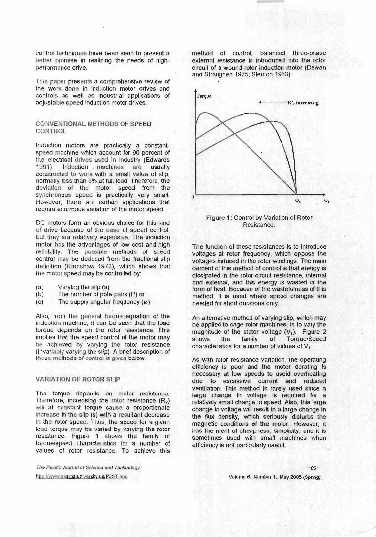
The torque depends on motor resistance. Therefore, increasing the rotor resistance (R2) will at constant torque cause a proportionate increase in the slip (s) with a resultant decrease in the rotor speed. Thus, the speed for a given load torque may be varied by varying the rotor resistance. Figure 1 shows the family of torquelspeed characteristics for a number of values of rotor resistance. To achieve this
method of control, balanced three-phase external resistance is introduced into the rotor circull of a wound-rotor inductiorl motor (Dewarr and Straughen 1975; Slemon 1966).
Torque I -- R', IncrcrzBg
Figure 1: Control by Variation of Rotor Resistance.
The function of these resistances is to introduce voltages at rotor frequency, whlch oppose the voltages induced in the rotor wndings. The main dement of thls method of control is that energy is . . . . . . . . . . . . . = . .
alsslpatea In tne roror-clrcun reslsrance, Internal and external, and this energy is wasted in the form of heat. Because of the wastefulness of this method, it is used where speed changes are needed for short durations only.
An alternative method of varying slip, which may be applied to cage rotor machines, is to vary the magnitude of the stator voltage (V,). Figure 2 shows the family of TorquelSpeed characteristics for a number of values of V,
ue to excessive current and reduced entitatton. This method is rarely used since a lrge change in voltage is required for a x l - + i s ~ n l s , ---I1 mb-.~--n in ----A Al -A +Li- I-.---
As with rotor resistance variation. the operating efficiency is poor and the motor defating is necessary at low speeds to avoid overheating d VI
12
rk~auvc~y alllall u ta l ~ y c III q x c u . nlaw, 11 113 ral yc
change in voltage will result in a large change in the flux density, which sefiously disturbs the magnetic conditions of the motor. However, it has the merit of cheapness, simplicity, and it is sometimes used with small machines when efficiency is not particularly useful.
The Pucific Journal of Science and Technology
Volume 8. Number 1. May 2005 (Spring)
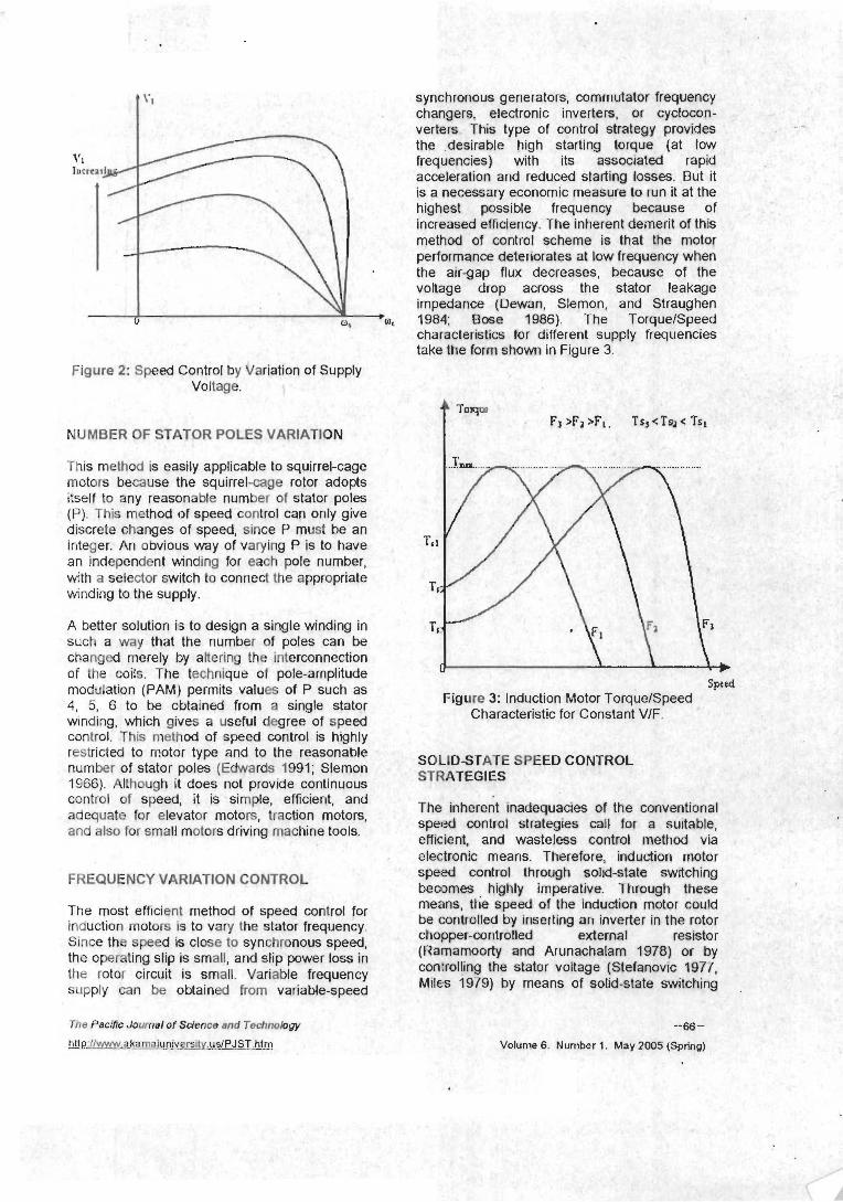
Figure 2: Speed Control by Variation of Supply Voltage.
NUMBER OF STATOR POLES VARIATION
This method is easily applicable to squirrel-cage motors because the squirrel-cage rotor adopts itself to any reasonable number of stator poles (P). This method of speed control can only give drscrete changes of speed, since P must be an integer. An obvious way of varying P is to have an independent windlng for each pole number, with a selector switch to connect the appropriate wnding to the supply.
A better solution is to design a single winding in such a way that the number of poles can be changed merely by altering the interconnection of the coils. The technique of pole-amplitude modulation (PAM) permits values of P such as 4. 5, 6 to be cbtained from a single stator winding, which gives a useful degree of speed control. This method of speed control is highly restricted to motor type and to the reasonable number of stator poles (Edwards 1991; Slemon 1966). Although it does not provide continuous control of speed, it is simple, efficient, and adequate for elevator motors, traction motors, and also for small motors driving machine tools.
FREQUENCY VARIATION CONTROL
The most efficient method of speed control for induction motors is to vary the stator frequency. Since the speed is close to synchronous speed, the operating slip is small, and slip power loss in the rotor circuit is small. Variable frequency supply can be obtained from variable-speed
The Pacific Journalof Science and Technology
htt~w.akamaiuniversity. i~slPJST.htm - -- - - - - - - -. - -. -- -. .
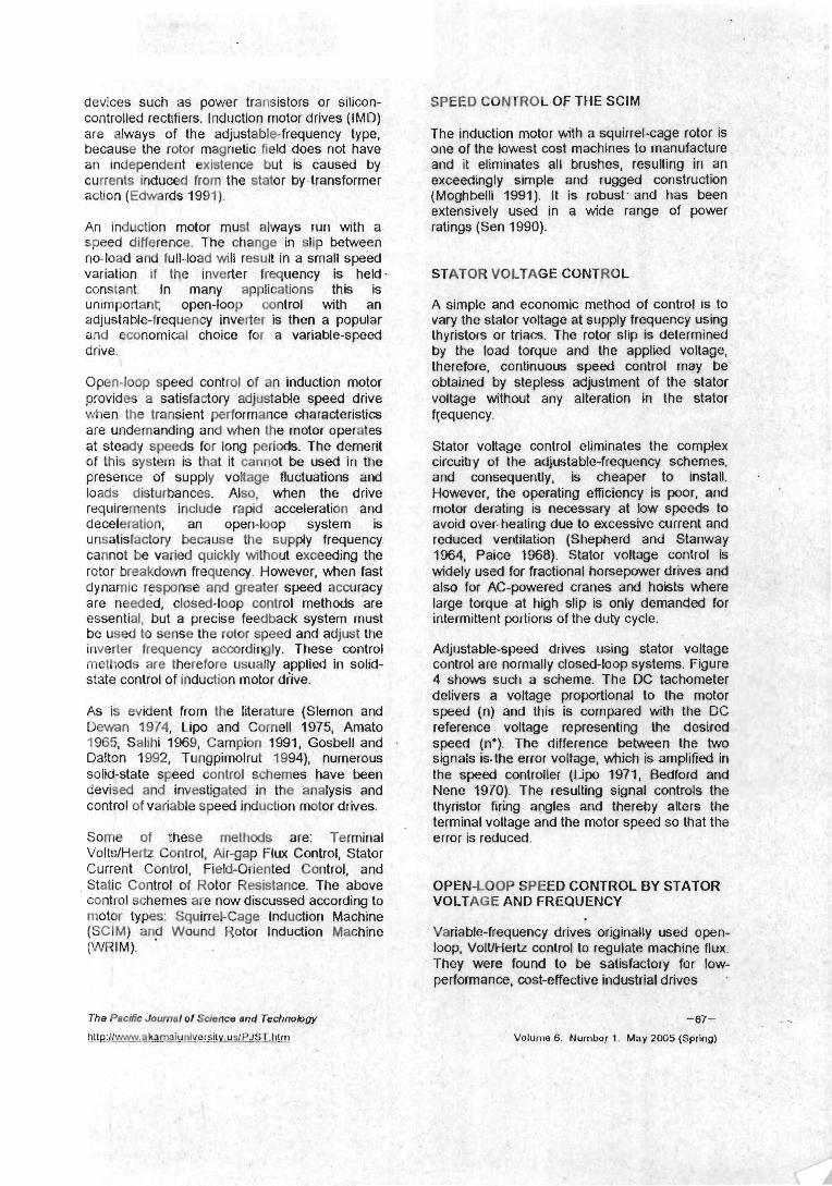
synchronous generators, commutator frequency changers, electronic inverters, or cyclocon- verters. This type of control strategy provides the desirable high starting torque (at low frequencies) with its associated rapid acceleration and reduced slarting losses. But it is a necessary economic measure lo run it at the highest possible frequency because of increased effciency. The inherent demerit of this method ol control scheme is that the motor performance deteriorates at low frequency when the air-gap flux decreases, because of the voltage drop across the stator leakage impedance (Dewan, Slemon, and Straughen 1984; Bose 1986) The TorquelSpeed characteristics lor different supply frequencies take the form shown in Figure 3.
Speed
efficient, and wasteless control method via electronic means. Therefore, induction motor speed control through solid-state switching becomes highly imperative. Through these means, the speed of the induction motor could be controlled by inserting an inverter in the rotor chopper-controlled external reststor (Ramamoorty and Arunachalam 1978) or by con:rolling the stator voltage (Stefanovic 1977, Miles 1979) by means of solid-state switching
-66-
Volume 6. Number 1. May 2005 (Spring)
devices such as power transistors or silicon- controlled rectifiers, lnduction motor drives (IMD) are always of the adjustable-frequency type, because the rotor magnetic field does not have an ~ndependent existence but is caused by currents induced from the stator by transformer action (Edwards 1991).
An induction motor must always run with a speed difference. The change in slip between no-load and full-load will result in a small speed variation i f the inverter frequency is held constant. In many applications this is unimportarit; open-loop control with an adjustable-frequency inverter is then a popular and economical choice for a variable-speed drive.
Open-loop speed control of an induction motor provides a satisfactory adjustable speed drive when the transient performance characteristics are undemanding and when the motor operates at steady speeds for long periods. The demerit of this system is that it cannot be used in the presence of supply voltage fluctuations and loads disturbances. Also, when the drive requirements ~nclude rapid acceleration and deceleration, an open-loop system is unsatisfactory because the supply frequency cannot be varied quickly without exceeding the rotor breakdown frequency. However, when fast dynamic response and greater speed accuracy are needed, closed-loop control methods are essential, but a precise feedback system must be used to sense the rotor speed and adjust the inverler frequency accordingly. These control methods are therefore usually applied in sohd- state control of induction motor diive.
As is evident from the literature (Slemon and Dewan 1974, Lipo and Cornell 1975, Amato 1965, Salihi 1969, Campion 1991, Gosbell and Dalton 1992, Tungpimolrut 1994), numerous solicl-state speed control schemes have been devised and investigated in the analysis and control of variable speed induction motor drives.
Some of :hese methds are: Terminal VoltdHertz Control, Air-gap Flux Control, Stator Current Control, Field-Oriented Control, and
. Static Control of Rotor Resistance. The above control schemes are now discussed according to motor types: SquirreCCage lnduction Machine (SCIM) and Wound Rotor Induction Machine (WRIM).
SPEED CO NTROL OF THE SCIM
The induction motor with a squirrel-cage rotor is one of the lowest cost machines to manufacture and it elinmates all brushes, resulting in an exceedingly simple and rugged construction (Moghbelli 1991). It is robust. and has been extensivelv used in a wide ranae of Dower I
-, - - 7 - - . . . . . . . . . . . -.
therefore, continuous speed control may be ~btained by stepless adjustment of the stator doltage without any alteration in the stator f1;equency.
Stator voltage control eliminates the complex . . -1 .L_ - - . : . _ - * - L a - r_-___.__- - . . ̂ ^h ---- ctrcuwy or we ajus~au~e-~requur~r;y scrtellles,
and consequently, is cheaper to install. . However, the operating efficiency is poor, and motor derating 'is necessary at iow speeds to avoid over-heating due to excessive current and reduced ventilation (Shepherd and Stanway 1964, Paice 1968). Stator voltage control is widely used for fractional horsepower drives and also for AC-powered cranes and hoists where large torque at high slip is only demanded for intermittent porlions of the duty cycle.
Adjustable-speed drives using stator voltage control are normally closed-loop systems. Figure 4 shows such a scheme. The DC tachometer delivers a voltage proportional to the motor speed (0) and this is compared with the DC reference voltage representing the desired speed (n*). The difference between the two signals isthe error voltage, which is amplified in the speed controller (Lipo 1971, Bedford and Nene 1970). The resulting signal controls the thyristor firing angles and thereby alters the b.-.s-i--l .,.-.I&--- --A 4 L m --.-.-A -.-. 4 k - 4 bL.-. LC1 l l Ill ldl VUILdYC: d l lU tl It: IllULUl 5)JCCU JU Ll Id1 LI IC
error is reduced.
OPEN-LOOP SPEED CONTROL BY STATOR VOLTAGE AND FREQUENCY
Variable-frequency drives originally used open- loop, VolUHertz control to regulate machine flux. They were found to be satisfactory for low- performance, cost-effective industrial drives
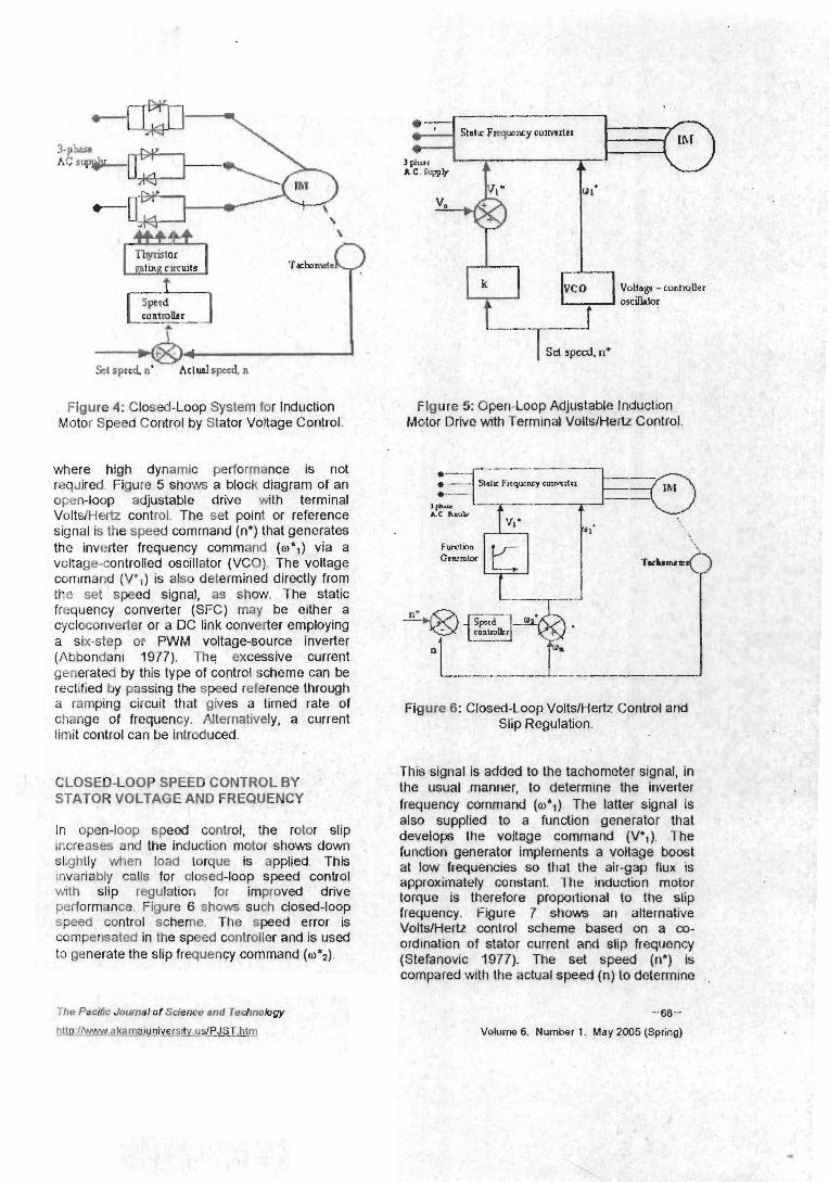
Figure 4: Closed-Loop System for Induction Motor Speed Control by Stator Voltage Control
where high dynamic performance is not required. Figure 5 shows a block diagram of an open-loop adjustable drive with terminal Volts/Wertz control. The set point or reference signal is the speed command (n*) that generates the inverter frequency command ((I)*,) via a voltage-controlled oscillator (VCO). The voltage ccrrrmand (V*,) is also determined directly from the set speed signal, as show. The static frequency converter (SFC) may be either a cycloconverter or a DC link converter employing a six-step or PWM voltage-source inverter (Abbondani 1977). The excessive current generated by this type of control scheme can be rectified by passing the speed reference through a ramping circuit that gives a timed rate of change of frequency. Alternatively, a current limit control can be introduced.
CLOSED-LOOP SPEED CONTROL BY STATOR VOLTAGE AND FREQUENCY
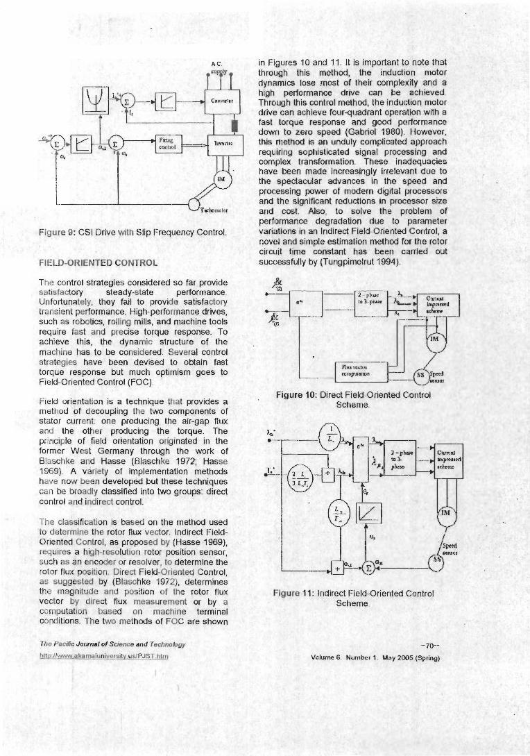
In open-loop speed control, the rotor slip Increases and the induction motor shows down sllghtly when load torque is applied. This ~nvariably calls for closed-loop speed control with slip regulation lor iniproved drive performance. Figure 6 shows such closed-loop speed control scheme. The speed error is cornperisated in the speed controller and is used to generate the slip frequency command (w*.4.
The Pacific Journal of Science and Technobgy
h w P 9 ~ akama_i~~vp~slty.u_s/PJST.htm
VoltslHem control Scheme based on a co- ordination of stator current and slip frequency (Stefanovic 1977). The set speed In') is compared with the actual speed (n) to determine .
-68-
Volume 6. Number 1. May 2005 (Spring)

the speed error, which is then passed through the speed controller and defines the inverter frequency and voltage.
Figure 7 : Closed-Loop L Current L
The current-limit signal c the motor current rises 1
level. This signal then co the inverter frequency an(
AIR-GAP FLUX CONTR(
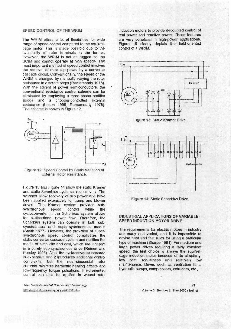
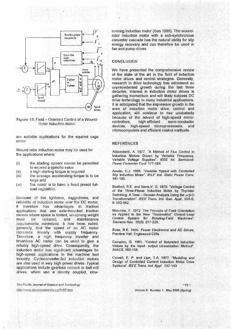
1 Figures 10 and 11. It is important to note that irough this method, the induction motor lynamics lose .most of their complexity and a ~igh performance drive can be achieved. -hrough this control method, the induchon motor Irive can achieve fourquadrant operation w~th a ast lorque response and good pwformance lown to zero speed (Gabriel 1980). However, his method is an unduly complicated approach equiring sophisticated signal processing and
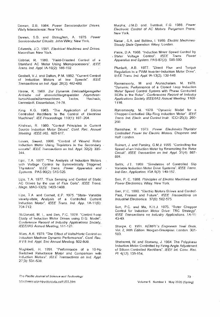
SPEED CONTROL OF THE WRIM
The WRIM offers a lot of flexibilities for wide range of speed control compared to the squirrel- cage motor. This is made possible due to the control OT a v v t a ~ . availability of rotor terminals in the former. However, the WRIM is not as rugged as the SClM and cannot operate at high speeds. The . most important method of speed corltrol involves the removal of rotor slip power by a converter cascade circuit. Conventionally, the speed of the WRlM is changed by manually varying the rotor resistance in discrete steps (Ramamoorty 1978). With the advent of power semiconductors, the conventional resistance control scheme can be eliminated by employing a three-phase rectifier bridge and a chopper-controlled external res~stance (Lesan 1996, Ramamoorty 1978). The scheme is shown In Figure 12.
Figure 12: Speed Control by Static Variation of External Rotor Resistance.
Figure 13 and Figure 14 show the static Kramer and static Scherbius systems, respectively. The systems allow recovery of slip power and have been applied extensively for pump and blower drives. The Kramer system provides sub- synchronous speed control while the cycloconverter in the Scherbius system allows for bi-directional power flow. Therefore, the Scherbius system can operate in both sub- synchronous and super-synchronous modes (Smith 1977). However, the provision of super- synchronous speed control complicates the static converter cascade system and nullifies the merits of sirnplic~ty and cost, which are inherent in a purely subsynchronous drive (Reinert and Parsley 1995). Also, the cycloconverter cascade is expensive and it introduces additional control complexity, but the near-sinusoidal rotor currents minimze harmonic heating effects and low-frequency torque pulsations. Field-oriented ,.,-.."-,.- r..,,.r-, ..,",,,".""-v,", -,.., .."",", U.".,
control can also be applied in wound rotor
The Pacific Journal of Sdence and Technokgy
~ ~ : ~ l ~ ~ ~ , a k a m a i ~ n i ~ ~ e r s i t y ~ u ~ I P J S T . h t ~ ~ )
-71 - Volume 6. Number 1. May:2005 (Spring)
running induction mot
cMlprrnor rotc~r induction m o b converter cascade ha energy recovery and b a l l I I I c I ~ I U I ~ LIc - fan and pump drives.
We have presented the comprehensive review of the state of the art in the field of induction motor drives and control strategies. Generally, research in drive technology has witnessed all unprecedented growth during the last three
Dewan, S.B. 1984. Power Semiconductor Drives W~ely Interscience: New York.
Dewan, S.B. and Straughen, A. 1975. Power Semiconductor Circuits. John W~ley: New York.
Edwards, J.D. 1991. Electrical Machines and Drives. Macrnillian: New York.
Gabriel, R. 1980. "Field-Oriented Control of a Standard AC Motor Using Microprocessors". IEEE Trans. Ind. Appl. IA-16(2): 186-1 92.
Gosbell. V.J. and Dalton, P.M. 1992. 'Current Control of lnduction Motor; at low Speeds", IEEE Transactions on Ind. Appl. 28(2): 482489.
H a w . K. 1969. Zur Dynarnik DrehzahlgeregeMer Antriebe mi l stromncl~tergespeisten Asynchron- - .
kurschlussleilfermascl,inen. Techn. ~ochsch; Darmstadt. Dissertation, 74-78.
King, K.G. 1963. "The Application of Silicon Controlled Rectifiers to the Control of Electrical Machines'. IEE Proceedings. 1 1 O(1): 197- 204.
Krishran. R. 1980. 'Control Principles in Current Source Induotion Motor Drives". Conf. Rec. Annual Meeting. IEEE-IAS. 605-617.
Lesan, Saeed. 1996. "Control of Wound Rotor lnduction Motor Using Thyristors in the Secondary . circuits'. IEEE Transactions on lnd. Appl. 32(2): 335- 344.
Lipc,, T.A. 1977. "The Analysis of lnduction Motors . with Voltage Control by Symmetrically Triggered Thyilstors", IEEE Trens. Power Apparatus end . Systarns. PAS-90(2): 51 5-525.
Lipo, T.A. 1977. "Flux Sensing and Control of Static AC Oiives by the use of Flux Coils'. IEEE T r a r ~ . Megn. MAG-1 3(5): 1403-1 408.
Lipo, T.A. and Cornell, E.P. 1975. 'State- Variable steadystate. Analysis of a Controlled Current Induction Motor". IEEE Trans. Ind. App. 1 A-1 l(6): 704-71 2.
McDonald. M. L. and Sen, P.C. 1978. "Control Loop Study of lnduction Motor Drives using D.Q. Model". Conference Record of Industry Applications Society, IEEUIAS Annual Meeting, 11 1-1 21.
Mlles, A.R. 19713. 'The Effect of VoltslHertz Control on InducZion Machine Dynamic Performance". Conf. Rec. IEEE Ind. Appl. Soc Annuel Meeting. 802-809.
Moghbelli, H. 1991. "Performance of a 10-Hp Switched Reluctance Motor and Comparison with lnduction Motors". IEEE Transactions on Ind. Appl. 27(3): 531 -538.
Murphy, J.M.D. and. Turnbull, F.G. 1988. Power Electronic Control of AC Motors. Perganlon Press: New York.
Nasar , S.A. and Boldea, 1. 1990. Electric Mechines- Steady Stele Operation. Wley: London.
Paice, D.A. 1968. "Induction Motor Speed Control by Stator Voltage Control". IEEE Trens. Power . Apparatus and System. PAS-87(2): 585-590.
Plunkett, A.B. 1977. 'Direct Flux and Torque Regulation in a PWM Inverter-Induction Motor D~ive". IEEE Trens. Ind. Appl. IA-13(2): 139-1 46.
Ramamoorty, M. and Arunachalarn, M. 1978. 'Dynamic Performance of a Closed Loop lnduction Motor Speed Control System with Phase Cor~trolled SCRs in the Rotor". Conferences Record of Irtdustry Applications Society IEEEUAS Annual Meeting. 11 09- 1116.
Rarnamoorty, M. 1978. "Dynamic Model for a Chopper-Controlled Slip-Ring lnduction Motor". IEEE Trerts. Irxd. Electr. and Control Instr. IECI-25(3): 260- 266.
Ramshaw, R. 1 973. Power Electronics-Thyridor Controlled Power for Electric M o t o ~ . Chapman and Hall: London.
Reinert, J. and Parsley, G.M.J. 1995. "Controlling the Speed of a n lnduction Motor by Resonating the Rotor Circuit", IEEE Trartsaction on lnd. Appl. 31(4): 887- 091.
Salihi, J.T. 1969. "Simulation of Controlled Slip Variable lnduction Motor Drive Systems". IEEE Trens. Ind Gen. Application. IGA 5(2): 149-1 57.
Sen, P. C. 1988. Principles of Electric Machines end Power Eledronics. Wey : New York.
Sen, P.C. 1990. "Electric Motors Drives and Control- Past, Present and Future". IEEE Trarlsactions on Industrial Eledronics. 37(6): 562-575.
Sen, P.C. and Ma, K.H.J. 1975. 'Robr Chopper Control for lnduction Motor Driva: TRC Strategy". IEEE Trensections on. Industry Applicatior)~. .I A-I I : . 43-49.
Sharpe. C. 1991. KEMPE's E n g i n e e ~ Year Book, Vol. 2, 96th Edition. Morgan-Grampian: London. 301- 503.
Shehered, W. and Stanway, J. 1964. The Polyphase lnduction Motor Controlled by Firing Angle Adjustment of Silicon Controlled Rectifiers". IEEE 1/71. Conv. Rec. Pt. 4(12): 135-1 54.
The Pacnlc Journel of Scrence and Technology
hlrp_~~~a&ar~~_u~!y.ers~iv udPJST htm
-73-
Volume 6. Number 1. May 2005 (Spring)
Slernon, G.R. : 966. Magnetoelectric Devices- Transducers, . Transfonnnrs end Machines. John 'Ahley: New York.
Slttrnon, G.R and Dewan, S.B. 1Y74. "Induction Motor Drive with Current Source Inverter". Conf. Rec. IEEE Ind Appl. Meefing, Soc. Annual Meeling. 41 1-417.
Smith, G.A. 1977. "Static Scherbius System of Induction-Motor Speed Control". Proc. IEE. 124(6): 557-560.
Stefanovic , V.R. 1977. "Closed Loop Performance of Induction Motors with Constant VoItslHertz Control". Electr. Mecti. and Electrornechenicol. l(3): 255-266.
Tungpimolrut, Kanokvate. 1994. "Robust Vector Conbol of lnduction Motor without using Stator and Rotor Circuit Time Constants". IEEE Transaction on Ind. App. 30(5): 1'241 - 1246.
Dr. M. U. Agu holds a Ph 0. in Power Electronics from the University of Toronto, Canada. He lectures in the Department of Electrical Engineering, University of Nigeria, Nsukka. His research interests include Power Electronics and Control of Electric drives. He is a member of the NSE and the IEEE.
SUGGESTED CITATION
Okoro, 0.1. and M.U. Agu. 2005. 'Induction Motor Control Strategies: Past and Present". Pacific Journal of Science and Technology. 6(1):64-74
Pacific Journal of Science an-d Technology A --
ABOUT THE AUTHORS
Dr.-lng. Ogbonnaya lnya Okoro holds a Ph.D. In Electrical machines from the University of Kassel, Germany. He currently lectures in the Department of Electrical Engineering, University of Nigeria, Nsukka. His research interests are dynamic simulation and control of induction machine, thermal and dynamic analysis of AC machines. He is a member of the IEEE and the Solar Energy Society of Engineers.
The Pac:fic Journalof Science and Technology
hltp / / w ~ d akarna~ul~ps~ty us/PJS T htrn -74-
Volume 6. Number 1. May 2005 (Spring)
Related Documents