University of Groningen Machine design and electron beam control of a single-pass linac for free electron laser Di Mitri, Simone IMPORTANT NOTE: You are advised to consult the publisher's version (publisher's PDF) if you wish to cite from it. Please check the document version below. Document Version Publisher's PDF, also known as Version of record Publication date: 2011 Link to publication in University of Groningen/UMCG research database Citation for published version (APA): Di Mitri, S. (2011). Machine design and electron beam control of a single-pass linac for free electron laser: The FERMI@Elettra case study. [s.n.]. Copyright Other than for strictly personal use, it is not permitted to download or to forward/distribute the text or part of it without the consent of the author(s) and/or copyright holder(s), unless the work is under an open content license (like Creative Commons). The publication may also be distributed here under the terms of Article 25fa of the Dutch Copyright Act, indicated by the “Taverne” license. More information can be found on the University of Groningen website: https://www.rug.nl/library/open-access/self-archiving-pure/taverne- amendment. Take-down policy If you believe that this document breaches copyright please contact us providing details, and we will remove access to the work immediately and investigate your claim. Downloaded from the University of Groningen/UMCG research database (Pure): http://www.rug.nl/research/portal. For technical reasons the number of authors shown on this cover page is limited to 10 maximum. Download date: 25-02-2022

Welcome message from author
This document is posted to help you gain knowledge. Please leave a comment to let me know what you think about it! Share it to your friends and learn new things together.
Transcript

University of Groningen
Machine design and electron beam control of a single-pass linac for free electron laserDi Mitri, Simone
IMPORTANT NOTE: You are advised to consult the publisher's version (publisher's PDF) if you wish to cite fromit. Please check the document version below.
Document VersionPublisher's PDF, also known as Version of record
Publication date:2011
Link to publication in University of Groningen/UMCG research database
Citation for published version (APA):Di Mitri, S. (2011). Machine design and electron beam control of a single-pass linac for free electron laser:The FERMI@Elettra case study. [s.n.].
CopyrightOther than for strictly personal use, it is not permitted to download or to forward/distribute the text or part of it without the consent of theauthor(s) and/or copyright holder(s), unless the work is under an open content license (like Creative Commons).
The publication may also be distributed here under the terms of Article 25fa of the Dutch Copyright Act, indicated by the “Taverne” license.More information can be found on the University of Groningen website: https://www.rug.nl/library/open-access/self-archiving-pure/taverne-amendment.
Take-down policyIf you believe that this document breaches copyright please contact us providing details, and we will remove access to the work immediatelyand investigate your claim.
Downloaded from the University of Groningen/UMCG research database (Pure): http://www.rug.nl/research/portal. For technical reasons thenumber of authors shown on this cover page is limited to 10 maximum.
Download date: 25-02-2022
Chapter 2
The FERMI@ElettraLinac-based FEL
2.1 Overview
The FERMI single-pass FEL facility1 is driven by the Elettra 3 GHz S-band linacupgraded with seven structures from CERN, following the completion of theconstruction of a new injector booster complex for the storage ring [31]. The ac-celerator and FEL complex comprises the following parts: a photo-injector gen-erating a bright electron beam, the main linear accelerator in which the beamis time-compressed and accelerated up to 1.5 GeV, the system to transport thebeam to the undulators, the undulator complex generating the FEL radiation,the photon beamlines taking the radiation from the undulator to the experimen-tal area and the experimental area itself. After leaving the undulators, whilethe FEL radiation is transported to the experimental area, the electron beam isbrought to a beam dump by a sequence of bending magnets. The whole infras-tructure is installed about 5 m below ground level. Figure 2.1 shows a schematicplan (on scale) of the Elettra Laboratory. The circular building containing theElettra synchrotron is visible at center. Below, the FERMI@Elettra linac, undu-lator hall and experimental hall infrastructure is shown (the electron beam goesfrom right to left). Figure 2.2 shows a sketch (not to scale) of the FERMI@Elettraaccelerator, FEL and experimental beamlines complex.
The new RF photo-injector, low emittance electron source is based on the
1This Chapter is based on the following technical note, later included in the FERMI@Elettra Con-ceptual Design Report: FERMI@Elettra Accelerator technical Optimization Final Report, ST/F-TN-06/15(2006), by M. Cornacchia, P. Craievich, S. Di Mitri, I. Pogorelov, J. Qiang, M. Venturini, A. A. Zho-lents, D. Wang and R. Warnock.
15

Figure 2.1: Plan of the Elettra Laboratory.
proven 1.6 cell electron gun developed at BNL/SLAC/UCLA [32]. Given thesimilarities between the LCLS FEL at SLAC [33] and the FERMI photo-injectorrequirements, this design draws heavily on the LCLS concept to produce a 5 to10 ps long pulse with ≤1 nC charge and an rms normalized transverse emit-tance≤1.0 mm mrad. The present repetition rate is 10 Hz, but the design allowsfor upgrading the photo-injector to 50 Hz, the maximum repetition rate of theRF systems at FERMI. Following standard layout schemes, the design includes asolenoid for emittance compensation [34, 35] and acceleration to 100 MeV withtwo S-band RF sections. A laser pulse provides temporal and spatial bunchshaping. The FERMI design calls for a novel temporal bunch profile in whichthe bunch current increases linearly with time (linear ramp) [17]. Such profileat the start of acceleration produces a more uniform energy and current profileat the entrance of the undulator. Two magnetic bunch compressors, BC1 andBC2, are at the energy of ∼350 MeV and at ∼600 MeV, respectively. They al-low continuously tunable compression of the bunch length by a factor from 1to ∼50. The nominal compression factor of 10 can be implemented with a two-stage compression or with BC1 only. The two schemes imply a different balanceof the parameters characterizing the final electron beam quality, such as cur-
16
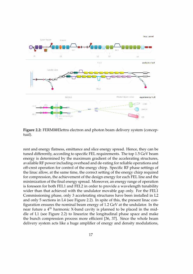
Figure 2.2: FERMI@Elettra electron and photon beam delivery system (concep-tual).
rent and energy flatness, emittance and slice energy spread. Hence, they can betuned differently, according to specific FEL requirements. The top 1.5 GeV beamenergy is determined by the maximum gradient of the accelerating structures,available RF power including overhead and de-rating for reliable operations andoff-crest operation for control of the energy chirp. Specific RF phase settings ofthe linac allow, at the same time, the correct setting of the energy chirp requiredfor compression, the achievement of the design energy for each FEL line and theminimization of the final energy spread. Moreover, an energy range of operationis foreseen for both FEL1 and FEL2 in order to provide a wavelength tunabilitywider than that achieved with the undulator movable gap only. For the FEL1Commissioning phase, only 3 accelerating structures have been installed in L2and only 5 sections in L4 (see Figure 2.2). In spite of this, the present linac con-figuration ensures the nominal beam energy of 1.2 GeV at the undulator. In thenear future a 4th harmonic X-band cavity is planned to be placed in the mid-dle of L1 (see Figure 2.2) to linearize the longitudinal phase space and makethe bunch compression process more efficient [36, 37]. Since the whole beamdelivery system acts like a huge amplifier of energy and density modulations,
17

a laser heater [38] is installed at 100 MeV just after the photo-injector to pro-vide control of the uncorrelated energy spread in the beam and minimize thepotential impact of the so-called microbunching instability on the current andparticle energy distribution. The uncorrelated energy spread induced by thelaser heater is able to suppress the modulation in the energy and density distri-butions at a scale small with respect to the bunch length. A timing system [39]based on the transmission of optical signals over a highly stabilized fiber op-tic system will distributes timing signals throughout the facility. This providessynchronization of the photo-cathode laser to the RF gun phase, stabilized drivesignals to RF systems in the facility and synchronization of the FEL seed laserwith the arrival time of the electron beam. The upgraded linac plus the complexof state-of-the-art undulators allow FERMI to cover the 100-20 nm wavelengthregion in the first FEL1 phase and to reach down to 4 nm in a later FEL2 phase.Wavelength tunability, variable polarization and higher electron beam energiesto reach even shorter output wavelengths are also in the machine delivery plan.The seeded FEL process occurs in the standard HGHG scheme for FEL1 and in atwo-stage cascade for FEL2. The X-ray pulse duration is essentially determinedby the seed laser duration. The photon beams from the FELs are transported inbeamlines to hutches and the adjoining downstream experimental hall. Lasersystems in the experimental area are synchronized to the FEL output using thestabilized optical timing system distributed around the facility.
2.2 Accelerating Structures
The accelerator uses three types of structures. Two SLAC-type structures in L0follow the electron gun and are used for the initial acceleration and the emit-tance compensation scheme. A detailed description of the injector and its pa-rameters can be found in [29]. Seven CERN-type structures (C1-C7) are dividedbetween L1 (4 structures) and L2 (3 structures), located upstream and down-stream of BC1, respectively. All these are traveling wave (TW) structures op-erating in the 2π/3 mode. Seven Elettra-type structures (S1-S7) make up L3 (2structures) and L4 (5 structures), located upstream and downstream of BC2, re-sepctively. They are backward traveling wave (BTW) structures operating in the3π/4 mode. The inner geometries of the accelerating structures are differentfor each type of the afore-mentioned elements: the SLAC-type and the CERN-type structures are configured in TW forward wave mode with on-axis couplingand operated a relatively modest gradient of 15 MV/m. The geometry of theElettra-type structures corresponds to a nose-cone type structure with magneticcoupling; these operate in BTW mode and at high gradient, up to 25 MV/m.The magnetic coupling in the BTW structures allows them to provide a higher
18
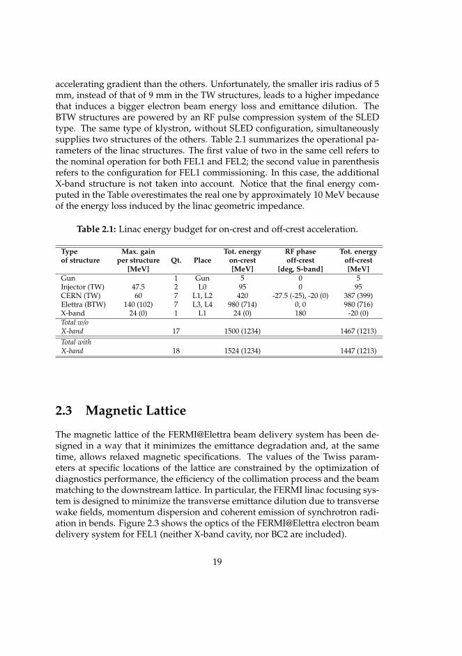
accelerating gradient than the others. Unfortunately, the smaller iris radius of 5mm, instead of that of 9 mm in the TW structures, leads to a higher impedancethat induces a bigger electron beam energy loss and emittance dilution. TheBTW structures are powered by an RF pulse compression system of the SLEDtype. The same type of klystron, without SLED configuration, simultaneouslysupplies two structures of the others. Table 2.1 summarizes the operational pa-rameters of the linac structures. The first value of two in the same cell refers tothe nominal operation for both FEL1 and FEL2; the second value in parenthesisrefers to the configuration for FEL1 commissioning. In this case, the additionalX-band structure is not taken into account. Notice that the final energy com-puted in the Table overestimates the real one by approximately 10 MeV becauseof the energy loss induced by the linac geometric impedance.
Table 2.1: Linac energy budget for on-crest and off-crest acceleration.
Type Max. gain Tot. energy RF phase Tot. energyof structure per structure Qt. Place on-crest off-crest off-crest
[MeV] [MeV] [deg, S-band] [MeV]Gun 1 Gun 5 0 5Injector (TW) 47.5 2 L0 95 0 95CERN (TW) 60 7 L1, L2 420 -27.5 (-25), -20 (0) 387 (399)Elettra (BTW) 140 (102) 7 L3, L4 980 (714) 0, 0 980 (716)X-band 24 (0) 1 L1 24 (0) 180 -20 (0)Total w/oX-band 17 1500 (1234) 1467 (1213)Total withX-band 18 1524 (1234) 1447 (1213)
2.3 Magnetic Lattice
The magnetic lattice of the FERMI@Elettra beam delivery system has been de-signed in a way that it minimizes the emittance degradation and, at the sametime, allows relaxed magnetic specifications. The values of the Twiss param-eters at specific locations of the lattice are constrained by the optimization ofdiagnostics performance, the efficiency of the collimation process and the beammatching to the downstream lattice. In particular, the FERMI linac focusing sys-tem is designed to minimize the transverse emittance dilution due to transversewake fields, momentum dispersion and coherent emission of synchrotron radi-ation in bends. Figure 2.3 shows the optics of the FERMI@Elettra electron beamdelivery system for FEL1 (neither X-band cavity, nor BC2 are included).
19
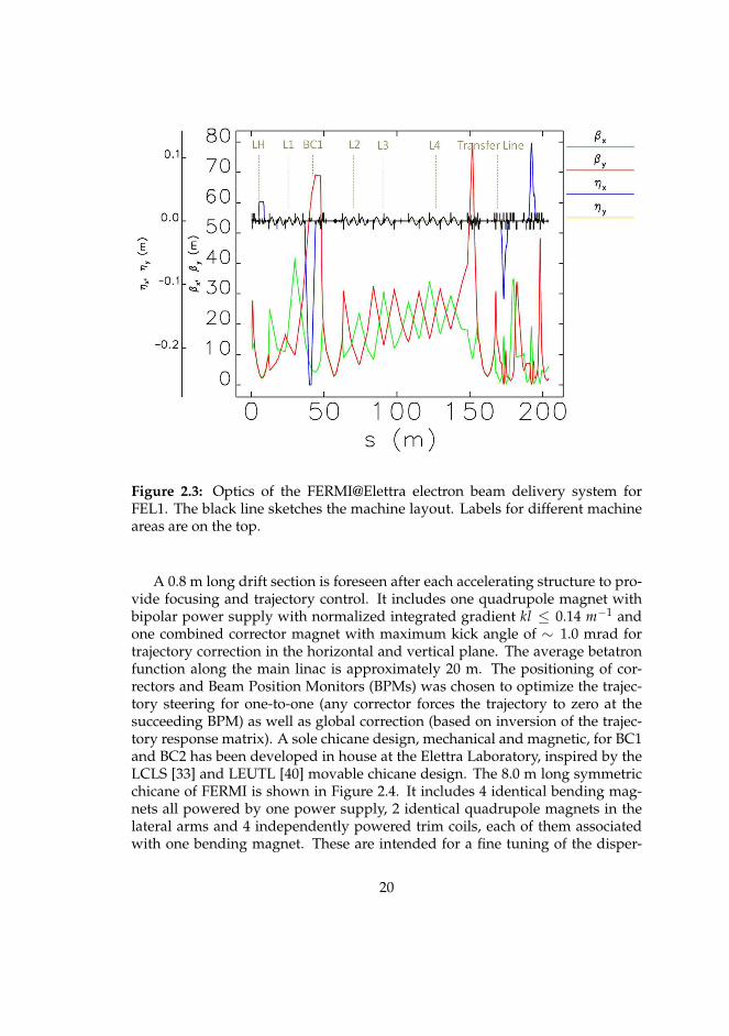
Figure 2.3: Optics of the FERMI@Elettra electron beam delivery system forFEL1. The black line sketches the machine layout. Labels for different machineareas are on the top.
A 0.8 m long drift section is foreseen after each accelerating structure to pro-vide focusing and trajectory control. It includes one quadrupole magnet withbipolar power supply with normalized integrated gradient kl ≤ 0.14 m−1 andone combined corrector magnet with maximum kick angle of ∼ 1.0 mrad fortrajectory correction in the horizontal and vertical plane. The average betatronfunction along the main linac is approximately 20 m. The positioning of cor-rectors and Beam Position Monitors (BPMs) was chosen to optimize the trajec-tory steering for one-to-one (any corrector forces the trajectory to zero at thesucceeding BPM) as well as global correction (based on inversion of the trajec-tory response matrix). A sole chicane design, mechanical and magnetic, for BC1and BC2 has been developed in house at the Elettra Laboratory, inspired by theLCLS [33] and LEUTL [40] movable chicane design. The 8.0 m long symmetricchicane of FERMI is shown in Figure 2.4. It includes 4 identical bending mag-nets all powered by one power supply, 2 identical quadrupole magnets in thelateral arms and 4 independently powered trim coils, each of them associatedwith one bending magnet. These are intended for a fine tuning of the disper-
20
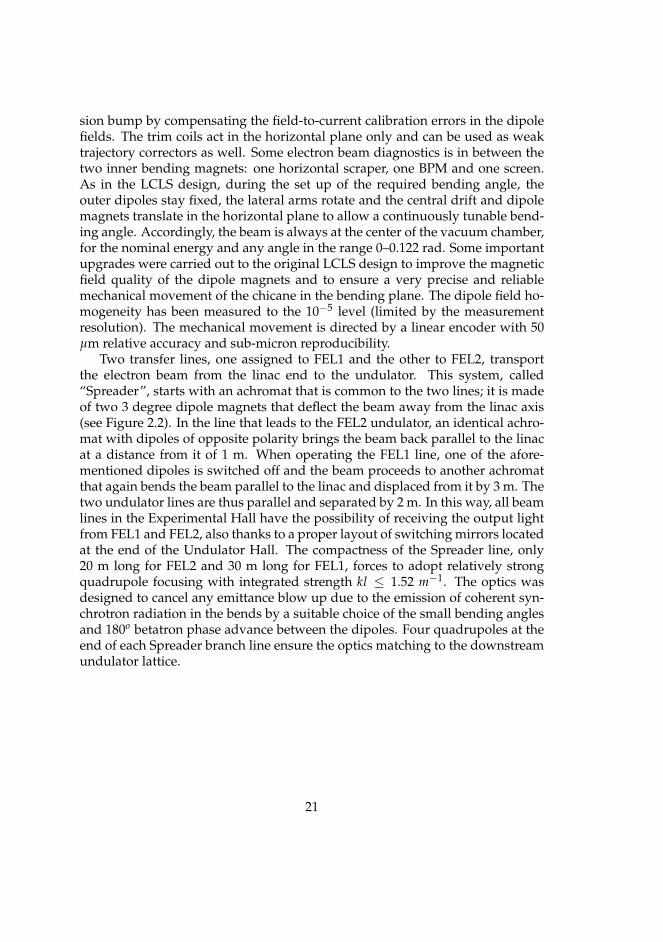
sion bump by compensating the field-to-current calibration errors in the dipolefields. The trim coils act in the horizontal plane only and can be used as weaktrajectory correctors as well. Some electron beam diagnostics is in between thetwo inner bending magnets: one horizontal scraper, one BPM and one screen.As in the LCLS design, during the set up of the required bending angle, theouter dipoles stay fixed, the lateral arms rotate and the central drift and dipolemagnets translate in the horizontal plane to allow a continuously tunable bend-ing angle. Accordingly, the beam is always at the center of the vacuum chamber,for the nominal energy and any angle in the range 0–0.122 rad. Some importantupgrades were carried out to the original LCLS design to improve the magneticfield quality of the dipole magnets and to ensure a very precise and reliablemechanical movement of the chicane in the bending plane. The dipole field ho-mogeneity has been measured to the 10−5 level (limited by the measurementresolution). The mechanical movement is directed by a linear encoder with 50µm relative accuracy and sub-micron reproducibility.
Two transfer lines, one assigned to FEL1 and the other to FEL2, transportthe electron beam from the linac end to the undulator. This system, called“Spreader”, starts with an achromat that is common to the two lines; it is madeof two 3 degree dipole magnets that deflect the beam away from the linac axis(see Figure 2.2). In the line that leads to the FEL2 undulator, an identical achro-mat with dipoles of opposite polarity brings the beam back parallel to the linacat a distance from it of 1 m. When operating the FEL1 line, one of the afore-mentioned dipoles is switched off and the beam proceeds to another achromatthat again bends the beam parallel to the linac and displaced from it by 3 m. Thetwo undulator lines are thus parallel and separated by 2 m. In this way, all beamlines in the Experimental Hall have the possibility of receiving the output lightfrom FEL1 and FEL2, also thanks to a proper layout of switching mirrors locatedat the end of the Undulator Hall. The compactness of the Spreader line, only20 m long for FEL2 and 30 m long for FEL1, forces to adopt relatively strongquadrupole focusing with integrated strength kl ≤ 1.52 m−1. The optics wasdesigned to cancel any emittance blow up due to the emission of coherent syn-chrotron radiation in the bends by a suitable choice of the small bending anglesand 180o betatron phase advance between the dipoles. Four quadrupoles at theend of each Spreader branch line ensure the optics matching to the downstreamundulator lattice.
21

Figure 2.4: FERMI@Elettra movable magnetic chicane for bunch length com-pression. Drawing courtesy of D. La Civita.
2.4 High Gain Harmonic Generation Free ElectronLaser
FERMI@Elettra FEL is based on the harmonic up-shifting of an initial seed signalin a single-pass FEL amplifier employing multiple undulators. The basic prin-ciples which underlie this approach are: the energy modulation of the electronbeam via the resonant interaction with an external seed laser in a first undula-tor, called “modulator”; the use of a dispersive section to then develop a strongdensity modulation with large harmonic overtones and the production of co-herent radiation by the microbunched beam in a downstream undulator, called“radiator”. The radiator is tuned at a harmonic of the seed laser wavelength.
The first stage of the project, FEL1, generates coherent output radiation in the20-100 nm spectral range. For these wavelengths, users require short (<100 fs)pulses with adjustable polarization and high temporal and spatial reproducibil-ity. FEL1 relies upon a single-stage, HGHG scheme (i.e., modulator-dispersive
22

section-radiator). The second stage, FEL2, extends the spectral range to 4 nm.For FEL2, a two-stage harmonic cascade is needed to reach short wavelengths.The selected configuration is based on the so-called “fresh bunch” approach [41],in which the output from the first radiator modulates the energy (in a subse-quent modulator) of a part of the electron beam that did not interact with theexternal seed. Both the FEL1 and FEL2 undulator layout is shown in Figure 2.2.If a seed laser source using harmonic generation in gas would become availableat ∼20 nm, FEL2 could be operated with a single up-shift in frequency as FEL1thus eliminating the double harmonic cascade. Design choices for FEL2 do notpreclude this attractive possibility. In the following, each element of the FEL1and FEL2 scheme are discussed in turn.
An external laser provides an initial, wavelength-tunable seed signal. Thissignal, in conjunction with the magnetic field generated by the modulator, pro-duces a relatively strong energy modulation ∆δ (δ is here the relative energy de-viation) of the beam electrons at the seed wavelength via resonant interaction.Figure 2.5 shows the energy modulation induced in the modulator. Following
Figure 2.5: Energy modulation induced by the external seeding laser in the mod-ulator of FEL1. The energy modulation amplitude ∆δ induced by the seedinglaser and the slice energy spread σδ,sli are indicated by arrows. The dotted linesenclosing the electron bunch are the separatrices that define the region of stable,periodic particle motion in the longitudinal phase space. Figure courtesy of G.De Ninno.
23

its exit from the modulator, the electron beam then passes through a dispersivesection in which a density modulation develops from path length differencesassociated with the energy modulation. As long as ∆δ � σδ,s, where σδ,s is therelative initial slice energy spread, a strong periodic density modulation is cre-ated at the wavelength λ0 of the seed laser, containing large higher harmoniccomponents, up to the harmonic number m ∼ ∆δ/σδ,s. At this point the electronbeam enters the radiator, whose wavelength and magnetic strength are tunedsuch that the FEL resonance occurs at an integer harmonic m of the original seedlaser wavelength. For FERMI, m varies between 3 and 6 for the first radiator. If,as in FEL1, this radiator is the final undulator, it generally is made sufficientlylong for the FEL radiation to grow to saturation (or even longer via tapering ifgreater output power is sought).
In the FEL2 fresh bunch approach, the duration of the electron bunch is atleast two times longer than the duration of the seed laser pulse. In this case radi-ation from the first radiator is used to energy-modulate part of the electron beamin a subsequent modulator; the first radiator is made only long enough that theradiation is sufficient to produce adequate downstream energy modulation. Theemitted radiation is effectively coherent spontaneous emission, whose powerscales as the square of the product of the current and the longitudinal distanceinside the undulator (ignoring diffraction and debunching effects). Followingthe first radiator is a section (essentially a chicane) that temporally delays theelectron beam in order to make the output radiation temporally coincident witha “fresh” section of the electron beam closer to the beam head. This fresh sectionof the bunch has not had its slice energy spread increased via FEL interaction inthe first stage. Thus, it can be far more easily energy- and density-modulatedin the second stage undulator than the “used” electron beam section that inter-acted with the seed laser pulse in the first modulator and radiator. The secondstage for the fresh bunch approach consists of a modulator, a final radiator, and,in general, an intervening dispersive section. The modulator uses the radia-tion from the first stage radiator as its seed radiation; it must therefore haveits undulator period and magnetic strength tuned to be resonant at that samewavelength. The harmonic up-shift factor between the second stage modulatorand radiator is 4 or less for the FERMI case. The second stage radiator is usuallymuch longer than that of the first stage both because the initial bunching is nor-mally smaller and because the FEL is normally run to saturation. The processof light emission in the final radiator includes at first a quadratic (as in the firststage) and then an exponential growth regime.
For the first modulator in FEL1 and FEL2, which must satisfy FEL resonanceover a nominal wavelength range of 240 to 360 nm, the undulator wavelengthselected, λu, is 100 mm for 30 periods. For the second stage modulator of FEL2,the adopted wavelength is 55 mm for 42 periods, matching that of the first stage
24
radiator. The choice of λu for the radiators is driven by two principal require-ments: 1) the FEL resonance be physically possible at the longest wavelength(i.e., 100 nm for FEL1 and 20 nm for FEL2) for beam energies of 1.2 GeV; 2) therebe sufficient gain (i.e., K ≥ 1, K being the normalized rms undulator magneticstrength) at the shortest desired output wavelength. FEL1 and FEL2 are requiredto provide, at all wavelengths, continuously tunable beam polarization rangingfrom linear-horizontal via circular to linear-vertical. The FEL1 radiator and thefinal radiator in FEL2 have therefore been chosen to be of the APPLE-II [42],pure permanent magnets type. For the modulator a simple, linearly-polarizedconfiguration is best, due to both its simplicity and because the input radiationseed can be linearly polarized. Wavelength tuning will be done by changingthe undulator gap (and thus K) rather than by changing the electron beam en-ergy. As the coupling between the radiation and the electron beam can dependstrongly on the beam radius, the FERMI design includes external quadrupolefocusing to produce an average value of 10 m for the betatron function in eachplane. The FEL1 and FEL2 radiators consist of 6 and 8 undulator magnets. Themagnetic length of the individual magnets is 2.3 m. The number of periods is 42in the FEL1 and first four FEL2 radiator segments (λu = 55 mm) and 66 in thelast four FEL2 radiator segments (λu = 35 mm). Electromagnetic quadrupoles,high resolution beam position monitors, and quadrupole movers are installedin between two consecutive undulator segments.
After leaving the undulators, the electron beam, carrying an average powerof 75 W at 50 Hz, is dumped into a shielding block by a sequence of bend-ing magnets, while the FEL radiation is transported to the experimental areas.Pulse length preservation, monochromatization, energy resolution, source shiftcompensation, focusing into the experimental chamber and beam splitting areall included in the design of the FEL radiation transport system. It is designedto handle the high power of up to 10 GW in a sub-ps long pulse. Its differ-entially pumped vacuum system is windowless, the low-Z material beam linecomponents operate at grazing incidence angles and the radiation intensity iscontrolled by a gas absorption cell.
2.5 Electron Beam Requirements
FEL1 and FEL2 output performance require a high electron beam quality at theentrance of the undulator and also set tight tolerances on the shot-to-shot repro-ducibility of the beam delivery system. The baseline FEL output specificationsfor FEL1 and FEL2 and the corresponding main electron beam parameters arelisted in Table 2.2. Present scientific proposals involve time-domain experimentssuch as pump-probe interactions, nonlinear phenomena, elastic and inelastic
25
scattering. Consequently, the requirements are related to the total photon num-ber per pulse (i.e., 0.42 · 1014), pulse duration (20–100 fs) and spectral bandwidth.
Depending on the experiments, an electron bunch final peak current of 500A or higher shall be provided. Including the inevitable inefficiency of the com-pression system, the maximum obtainable peak current is 800 A with 0.8 nC ofcharge from the photo-injector. Because in multi-stage operation the first stageradiation output power scales quadratically with the bunch current, the finaloutput power also drops sharply as the bunch current is lowered below design.Should one rely upon strong exponential gain in the final radiator, the outputpower would also be very sensitive to the beam current. A critical parameter af-fecting the required electron beam duration is the arrival time jitter of the beamrelative to that of the seed laser. The expected rms arrival time jitter from theaccelerator with respect to the seeding laser is 150 fs [29]. In order to ensuresufficient overlap between the seed and the electrons, the duration of the elec-tron bunch must be at least as long as 600 fs for 100 fs long seed pulses. Thecorrelations of the energy and charge distributions with the distance along theelectron bunch should be as small as possible in order not to broaden the FELbandwidth. The design values of energy and peak current variations along theusable part of the bunch are specified to be less than 2 · 10−4 and 100 A respec-tively. A multi-stage harmonic cascade is very sensitive to slice energy spreadbecause of the very nonlinear process leading to harmonic micro-bunching atthe seed frequency. A very sharp limit in fact exists on the tolerable electronbeam slice energy spread that aims a value of σE,s ≤ 200 keV for FEL1 and≤ 150keV for FEL2.
The electron beam optics and the photon beam brightness are affected by theelectron beam projected emittance, that therefore should be made as small aspossible. However, even in the case of a factor of 2 worse emittance, the opticsalong the undulator is generally recoverable since the beam size would only beincreased by a factor
√2 for the same average betatron function. Moreover, as
the seeding laser pulse is much shorter than the bunch length, the output pho-ton brightness depends on the slice emittance. In fact, the FEL saturation lengthis only affected by the slice emittance, which is the high priority parameter to beminimized. The horizontal and vertical, normalized slice emittances at the endof the FERMI linac should not exceed 1.5 mm mrad for FEL1 and 1.0 mm mradfor FEL2 to meet the desired photon output. This value, at least ∼ 20% higherthan predicted by photo-injector simulations, includes a safety margin againstemittance dilution effects. As an emittance of 1.0 mm mrad is demanded atthe shortest output wavelength, the accelerator performance is designed to sat-isfy this most stringent requirement. The specification could be relaxed duringlonger wavelength operation.
Albeit a complete jitter study is not in the outline of this thesis, we want to
26

point out that shot-to-shot repeatability is an important parameter associatedwith time domain experiments. Ideally, for nonlinear phenomena experiments,the shot-to-shot rms jitter in normalized photon number should be 5% or less.Such a low value seems unlikely with the presently expected accelerator and in-jector parameters. A large class of FEL1 experiments can tolerate values as highas 25% by recording the shot-by-shot photon number for post-processing. Al-though the total photon jitter is not critical for most experiments in the frequencydomain, shot-to-shot central wavelength jitter during narrow bandwidth opera-tion may be of concern unless the bandwidth can be maintained at or below therequired spectral resolution. So, in the operation the wavelength jitter shouldbe less than the individual shot bandwidth in order to not increase the effectivetime-averaged, output bandwidth as seen by the user. For both FEL1 and FEL2,calculations based on time-steady input parameters and full start-to-end time-dependent simulations were performed using the 3-D numerical codes Genesis[43] and Ginger [44]. They predict a satisfactory shot-to-shot output stabilityfor most of the planned experiments on both FEL1 and FEL2 if the followingspecifications for the electron beam stability are ensured at the entrance of theundulator: emittance jitter ∆ε/ε ≤ 10%, peak current jitter ∆I/I ≤ 8%, sliceenergy spread jitter ∆σδ,s/σδ,s ≤ 10%, mean energy jitter ∆E/E ≤ 0.1%.
Table 2.2: Main electron and photon beam parameters of FERMI FEL1 and FEL2.
FEL1 FEL1 FEL2 UnitsCommissioning Operation Operation
Electron Beam ParametersEnergy 1.2 0.9–1.2 1.2–1.5 GeVCharge 0.35 ≤ 0.80 0.80 nCSlice Norm. Emittance (rms) ≤ 1.5 1.5 1.0 mm mradSlice Energy Spread (rms) ≤ 0.10 ≤ 0.20 ≤ 0.15 MeVTotal Energy Spread (rms) ≤ 0.1 ≤ 0.1 ≤ 0.1 %Peak Current (flat region) 200–400 ≥ 500 800 ABunch Duration (fwhm) 0.7–1.3 0.7 0.7 psEnergy Jitter (rms) ≤ 0.1 ≤ 0.1 ≤ 0.1 %Arrival time jitter (rms) ≤ 200 ≤ 150 ≤ 150 fsPhoton Beam ParametersOutput Wavelength Range 40–60 20–100 4–20 nmOutput Pulse Duration (rms) ≤ 150 ≤ 50 ≤ 50 fsBandwidth (rms) 20–40 17 (at 40nm) 5 (at 10nm) meVPolarization Variable Variable VariablePeak Power ≥ 0.1 1–5 ≥ 0.3 GWPhotons per Pulse ≥ 1012 ≥ 1013 ≥ 1012 in 1meV bwPeak Power Stability ≤ 50 ≤ 30 ≤ 50 %Transverse Stability (rms) ≤ 50 ≤ 50 ≤ 50 µmRepetition Rate 10 50 50 Hz
27
2.6 Conclusions
The main parameters and layout of the FERMI@Elettra single-pass FEL havebeen introduced. The first stage of the project, FEL1, is based on the one-stageHigh Gain Harmonic Generation (HGHG) scheme that allows the 1.2 GeV elec-tron beam to emit at the FEL fundamental wavelength of 20 nm. FEL1 is presentlybeing commissioned and is nearly fully realized. The second stage of the project,FEL2, implements the two-stage HGHG scheme in the version of the so-calledfresh bunch technique. In this way, the 1.5 GeV electron beam could emit atthe fundamental wavelength of 4 nm. Commissioning of FEL2 is going to startat the end of 2011. Due to the relatively low energy of the electron beam, theharmonic up-shifting of an initial seed signal is an obliged choice for FERMI inorder to reach the FEL fundamental emission at such short wavelengths. At thesame time, the seeding interaction puts a tight constraint on the maximum sliceenergy spread of the electron beam at the undulator entrance that is approxi-mately 150 keV (rms value), only a factor of 5 bigger than the minimum the-oretical uncorrelated energy spread expected after bunch length compression.Peak power saturation at the fundamental wavelength is ensured by the sev-eral hundred’s Ampere electron beam with a normalized slice emittance equalor smaller than 1 mm mrad. To provide such high brightness electron beam,the S-band, normal conducting Elettra linac has been upgraded with other 7 ac-celerating structures from CERN. Only the Elettra structures should be able toprovide the remarkable accelerating gradient of 25 MV/m, instead of 15 MV/min the others, by virtue of the SLED system for RF pulse length compression.Unfortunately, the BTW structures have irises with inner radius of only 5 mm,instead of the 9 mm in the TW structures. Such a small radius excite strong lon-gitudinal and transverse wake fields that have to be carefully considered in themachine design and study of the electron beam dynamics. A movable, achro-matic, four dipole magnetic chicane has been designed to manage the magneticbunch length compression. Two of these chicanes, BC1 and BC2, are integratedin the linac magnetic lattice. A 30 m long transfer line brings the high energyelectron beam to the parallel undulator lines of FEL1 and FEL2. The electronbeam is finally dumped in the horizontal plane, while the emitted photons aretransmitted to the downstream photon beam lines for experiments.
28
Related Documents