I f 71-17,987 DIGGES, Kennerly H ite, 1933- THEORY OF AN AIR CUSHION LANDING SYSTEM FOR AIRCRAFT. The Ohio State University, Ph.D., 1970 Engineering, mechanical University Microfilms, A XEROXCompany, Ann Arbor, Michigan 0 Copyright by Kennerly Hite Digges 1971 THIS DISSERTATION HAS BEEN MICROFILMED EXACTLY AS RECEIVED

Welcome message from author
This document is posted to help you gain knowledge. Please leave a comment to let me know what you think about it! Share it to your friends and learn new things together.
Transcript
If
7 1 -1 7 ,9 8 7
DIGGES, Kennerly H ite , 1933-THEORY OF AN AIR CUSHION LANDING SYSTEM FOR AIRCRAFT.
The Ohio S ta te U n iv e r s ity , Ph . D. , 1970 E n g in eer in g , m echanical
University Microfilms, A XEROX C om pany, Ann Arbor, Michigan
0 C op y r ig h t by
K e n n e r l y H i te D i g g e s
1971
THIS DISSERTATION HAS BEEN MICROFILMED EXACTLY AS RECEIVED
T H E O R Y O F AN A IR C U SH IO N
LA N D IN G SY ST E M FO R A IR C R A F T
D IS S E R T A T IO N
P resen ted in Partial F u lf i l lm en t of t h e R e q u ire m en ts fo r
t h e Degree o f D o c to r of P h ilo so p h y in th e G rad u a te
S chool o f T h e O h io S ta te U niversity
By
K E N N E R L Y H . D IG G E S, B.S., M.Sc.
# * # * * *
T h e O h io S ta te U nivers ity •
1 9 7 0
A p p ro v e d by
/A dvisor
D e p a r tm e n t o f M echanical Engineering
PLEASE MOTE:
Some p ag es have sm a ll and i n d i s t i n c t ty p e .F ilm ed as r e c e iv e d .
U n iv e r s ity M icro film s
ACKNOWLEDGEMENTS
T h e a u th o r w ishes t o express his a p p re c ia t io n f o r t h e c o n t r ib u t io n s o f a n u m b e r
o f pe rso n s w h o greatly assisted in th is w o rk . F o r th e i r va luab le c o n t r ib u t io n s in c o n d u c tin g
tes ts , p lo t t in g curves, a n d m aking c o m p u ta t io n s th e e f fo r ts o f t h e fo llow ing pe rsonnel w ere
n o te w o r th y : B. J . B ro o k m an , G. R. W ycn, D. M. G o rm an , J. E. K rysiak, D. J . Perez, S.
C am pbell , D. J . Pool, a n d B. K. W ansgard . T h e ex p e r t ise o f S. Lam accia and K. J o h n s o n in
deve lop ing w o rk a b le c o m p u te r p ro g ram s was a su b s tan t ia l c o n t r ib u t io n to t h e success of
th is w o rk . F o r her excellence in g ram m atica l c o rre c t io n s an d in th e final ty p in g of th e
m an u sc r ip t , th e c o n t r ib u t io n o f Mary B rooks is g ra te fu lly acknow ledged .
Finally , th e a u th o r w ishes t o t h a n k Dr. Han, Dr. Fos te r , and Dr. D avidson fo r
th e i r m a n y I r T ’ful suggestions, an d pa rt icu la r ly Dr. S ta rk e y fo r his assistance,
e n c o u ra g e m e n t an d e n th u s ia sm during th e p ro jec t .
V ITA
195S B.S., M.E. w ith hono rs , M ech. Engr,, Virginia P o ly te c h n ic
In s t i tu te , B lacksburg, Virginia.
1 9 5 5 —1 9 5 6 M ain tenance Engineer, Esso S ta n d a rd Oil C o m p a n y ,
B altim ore , M aryland
1 9 5 6 - 1 9 6 0 A ero n au tica l R esearch Engineer , A irc ra f t L a b o ra to ry ,
W righ t-Pa tte rson A F B , O h io
1 9 6 0 —1 9 6 3 Chief, M echanical S ec tion , Air Force F ligh t D ynam ics
L a b o ra to ry , W righ t-Pa tte rson A F B , O h io
1 9 6 2 M.Sc., Mech. Engr., O h io S ta te University , C o lu m b u s, O hio
1 9 6 3 —1 9 7 0 Chief, M echanical B ranch , A ir Force F ligh t D ynam ics
L a b o ra to ry , W righ t-Pa tte rson A F B , O hio
PU B L IC A T IO N S
"D esign o f T ra n sp a re n t V ision A reas fo r O rb ita l G lide V eh ic le s ," p re se n ted a t U S A F /N A S A
C o n fe re n c e on Lifting M anned H yperve loc ity and R e-en try Vehicles, Langley R esearch C en ter,
Langley Field, Virginia, April 11-14, 1960.
" T h e Investiga tion o f T e c h n iq u e s fo r P red ic ting th e D ecom press ion R a te of Closed Vessels
E xhaus ting T h ro u g h a N ozz le a t Critical V e lo c i ty ," M.S. thesis , O h io S ta te U nivers ity , 1961.
" T h e A erospace Challenge to Bearing T e c h n o lo g y ," p re se n ted a t 1963 U S A F A erospace Fluids
a n d L u b r ic a n ts C o n fe ren ce , San A n to n io , T exas , April 16-19, 1963.
" A n A nalysis o f C on tro l Bearing R e q u ire m e n ts f o r Lifting R e-en try V eh ic le s ," A ero n au tica l
S y s tem s Division T echn ica l M em o A S R M F-T M -63-7 , J u n e 1963 .
"D esign o f High T e m p e ra tu re A irc ra f t W in d o w s ," p re se n ted a t t h e C o n fe re n c e o n T ra n sp a re n t
M ateria ls fo r A e ro sp ac e E nclosures , D ecem ber 8 -10 , 1964 .
" R e s u l t s o f S tu d ie s t o Im prove th e G ro u n d F lo ta t io n o f A irc ra f t ," p re se n ted a t th e SA E
A e ro sp ac e S y s tem s C o n fe ren ce , J u n e 27 -30 , 1967.
" T h e re A re M any W ays t o Im prove A b il ity o f A irc ra f t t o Land on Poo rly S u rfaced F ie lds ,"
T h e SA E Jo u rn a l , Vol. 76 , No. 9 , S e p te m b e r 1968 .
" A i r C u sh ion L and ing S y s tem fo r S T O L A irc ra f t , " V /S T O L T e c h n o lo g y and P lanning
Confere nce, S e p te m b e r 23 -25 , 1969 .
" A i r C ush ion Landing S y s tem D igest,” A F F D L T echn ica l M e m o ra n d u m 6 9 -1 0-FD FM ,
A pril 1969 .
TABLE OF CONTENTS
Page
A cknow ledgm ents
Vita iii
List o f Illustrations • viii
List o f Tables xi
List o f Sym bols xii
1. IN TRODU CTIO N 1
1.1 S ta te m e n t of the Problem 1
1.2 Background 2
1.3 The ACLS C oncep t 6
2. P E R IP H E R A L JE T FLOW RELA TIO N SH IPS 13
2.1 M ethod of A pproach to Problem 13
2.2 Background 13
2.3 D evelopm ent of C om m on Relationships 15
2 .4 General T echn ique fo r Developing F low Relationships 21
2 .5 T he T h in J e t T heory 31
2 .6 T he Exponen tia l T h eo ry 36
2.7 T he B arra tt T heo ry 39
2.8 Plenum T heory 46
3. COM PARISON OF FLOW T H E O R IE S 49
3.1 In troduc tion 49
3 .2 Recovery Pressure Ratio 50
3 .3 Nozzle T h ickness Param eter 52
3 .4 Pressure Coeffic ient 52
3 .5 Power Thickness P aram eter 56
3 .6 Power-Height Param eter 60
3 .7 A ugm en ta t ion R atio 60
3 .8 S u m m ary of Results 63
v
Page
4. PR E D IC T IO N OF T H E SH A PE OF A T W O D IM EN SIO N A L A lR
CU SHIO N T R U N K 67
4.1 A p p ro ach 67
4 .2 B ackground 674 .3 D eve lopm en t of C o m m o n R ela tionsh ips 7 0
4 .4 F re e 'T ru n k S hape 7 5
4 .6 L oaded T ru n k S hape 83
4 .6 T ru n k Cross Sectional Area 9 5
4 .7 ■ Analytical Results 97
5. A N A L Y SIS O F D IST R IB U T E D J E T FLOW 120
5.1 In tro d u c tio n 120
5.2 D is tr ibu ted J e t M o m e n tu m T h e o ry 123
5 .3 Flow R ostr ic to r T h e o ry 136
5.4 A naly tical Results 146
6 . E X P E R IM E N T A L P R O G R A M - S T A T I C M O D EL 151
6.1 E xperim enta l A p p a ra tu s - S ta tic T es ts 151
6.2 E xper im en ta l P rocedu res * S ta tic T es t * 153
6 .3 S u m m a ry of Results - S ta tic Tests , 155
7. DYNAM IC A N A L Y SIS OF T H E AIR CU SH IO N LANDING SY STEM 175
7.1 In tro d u c t io n 175
7 .2 S im ple D ynam ic Model 1807.3 Air Cush ion T ru n k D ynam ic A nalysis 189
7 .4 C om ple te Air Cushion Sys tem D ynam ic A nalysis 2 0 5
8 . E X P E R IM E N T A L PR O G R A M - DYNAM IC M O D EL 221
8.1 E xper im en ta l A p p a ra tu s — D ynam ic Tests 221
8 .2 D e te rm in a t io n o f Discharage C oeffic ien t Cx 226
8 .3 D e te rm ina t ion o f J e t T h ru s t an d Cz 2 2 9
8.4 D e te rm ina t ion o f A 3 and Cy 2 2 9
8 .5 D e te rm in a t io n o f T ru n k V olum e 2 3 5
8 . 6 Fan C haracte ris tics 2 4 0
8.7 D ynam ic Model T e s t 2 4 2
8 . 8 S u m m a ry o f D ynam ic T e s t Results 2 4 7
v i
Page
9. S U M M A R Y O F R E S U L T S 2 4 8
9.1 Design C o n s id e ra t io n s 2 4 8
9 .2 A irc ra f t V ariab les 2 5 0
9 .3 J e t S y s tem V ariab les 251
9 .4 T r u n k V ariab les 2 5 3
9 .5 P o w er S y s tem V ariab les 2 5 6
9 .6 P o w er R e q u ire m e n ts fo r t h e A C LS 2 5 7
9 .7 C o nc lu s ions 2 5 9
A p p e n d ix I F ree T r u n k S h a p e (Inelastic) 2 6 2
A p p e n d ix II Inelastic L oaded T r u n k S h a p e 271
A p p e n d ix III Elastic F ree T r u n k S h ap e 2 8 8
A p p e n d ix IV T ru n k C o n s t ru c t io n 291
A p p e n d ix V D e te rm in a t io n of F lo w Leakage 2 9 5
A p p e n d ix VI C o e f f ic ie n t o f D ischarge o f T r u n k 2 9 7
R efe rences 299
v i i
LIST OF ILLUSTRATIONS
Figure
1 - 1 A ir C ush ion S uspension S y s tem
Page
3
1 - 2 Historical G E T O L Designs 5
1-3 A r t is t 's C o n c e p t o f t h e A ir C ush ion L anding Sys tem 7
1-4 B raking S y s tem fo r ACLS 8
1-5 A C L S F o o tp r in t Pressure D is tr ibu tion 8
1 - 6 Historical A ir C ush ion V ehicles 1 0
1-7 C o m p a riso n o f A ir C ush ion Designs 1 2
2 - 1 A ir C ush ion M odel C o n f ig u ra t io n 17
2 - 2 M odel fo r General T h e o ry 23
2-3 M odel fo r T h in J e t an d E x p o n en t ia l T h e o ry 32
2-4 M odel fo r Barra it T h e o ry 4 0
3-1 N ozzle T h ick n ess P a ram e te r versus Pc /Pj
F lo w C o e f f ic ie n t versus Pc / P j
51
3-2 53
3-3 P ow er-T h ickness P a ram e te r versus Pc /Pj
Pow er-H eigh t versus Pc/P j, S im p le J e t T h e o ry
55
3 4(a) 57
3-4 (b) P ow er-H e igh t P a ra m e te r versus Pc /Pj, E x p o n e n t ia l T h e o ry 58
3-4(c) P ow er-H e igh t P a ra m e te r versus Pc /Pj, B a r ra t t T h e o ry 59
3-5 A u g m e n ta t io n versus J e t H eight to C ush ion D iam eter R a tio 62
4-1 Free T r u n k S hape 6 8
4-2 L oaded T r u n k S hape 69
4-3 Free B ody D iagram o f T r u n k L oading 7 4
4-4 Physical I n te rp re ta t io n o f Positive a n d Negative S q u a re R o o t 80
4-5 I llu s tra t ion o f M in im um T r u n k Length 90
4-6 G e o m e try fo r C alcu la ting th e U p p e r B ound fo r R-| 92
4-7 Physica lly Im possib le S o lu t io n 93
4-8 A ir C ush ion M odel 99
4-9 S ide T r u n k S h ap e 1 0 0
4-10 E nd T r u n k S h a p e 1 0 1
4-11 Y 0 versus Pc /Pj, S ide an d End T ru n k 103
4-12 X 0 versus Pc /P j, S ide an d End T r u n k .
A: versus Pn/P j, S ide a n d End T r u n k J ° JE lastic C urve fo r T r u n k M aterial
104
4-13 105
4-14 107
v i i i
Figure
4-15 T ru n k Length versus Pc /Pj, Elastic Side T runk
Page
108
4-16 YQ versus Pc/Pj, Elastic Side T ru n k 1 1 0
4-17 Y q versus Pc/Pj, Elastic End T ru n k 1 1 1
4-18 Aj versus Pc/Pj, Elastic Side T ru n k
Aj versus Pc/Pj, Elastic End T ru n k YQ versus Pc/Pj, Com parison o f Results
£ 3 versus Y q /Y ^ , Side T ru n k
1 1 2
4-19 113
4-20 114
4-21 116
4-22 £ 3 versus Y q /Y ^ , End T runk 117
4-23 Aj versus Y ^ Y ^ , Side T runk
Aj versus Y ^ Y ^ , End T ru n k
D istribu ted J e t G eom etry
118
4-24 119
5-1 126
5-2 T ru n k G eom etry fo r D istr ibuted Je t 130
5-3 T hree Cases for J e t Locations 133
5-4 Location of Je ts Relative to Low Point 139
5-5 Typical J e t Spacing 140
5-6 Analytical Predic tions of d / t versus Pc /Pj - Model Side T runk
Analytical Predic tions o f C q versus Pc /Pj - Model Side T runk
Sta tic (2D) Test Rig
143
5-7- 149
6 - 1 152
6 - 2 £l versus Pc/Pj Results
X0 versus Pc/Pj Results
Yc versus Pc/Pj Results
T ru n k Shape Results
156
6-3 157
6-4 158
6-5 159
6 - 6 £ 3 versus Y q / Y ^ Results, Pc/Pj = 0 161
6-7 £ 3 versus Y q / Y ^ Results, Pc/Pj = 0.41 162
6 - 8 Cushion Exhaust Pressure D istr ibu tion , P^/Pj = 0 .28
Cushion Exhaust Pressure D istr ibu tion , Pc /Pj = 0 .52
Cushion Exhaust Pressure D istr ibu tion , Pc /Pj = 0.7
C q versus Pc/Pj, Results
•168
6-9 169
6 - 1 0 170
6 - 1 1 173
6 - 1 2 d / t versus Pc/Pj Results
Sim ple Model fo r D ynam ic Analysis
174
7-1 179
7-2 Model fo r T ru n k D ynam ic Analysis 190
7-3 Model fo r Pressure D istr ibution Across the F o o tp r in t 199
7-4 Load-Deflection Characteristics o f the Cushion E xhaust Gap 2 0 0
7-5 Free Body Diagram fo r T ru n k F o o tp r in t 2 0 1
i x
Figure Page
7-6 Model fo r Air Cushion System Dynamic Analysis 204
7-7 X0 versus Y for Model T runk 208
7-8 M2 versus YQ f o r Model T runk 213
7-9 Centroidal Radius versus T runk Height for Model T runk 216
8-1 Dynamic Model and Test Platform 222
8-2 Hydraulic M otor Characteristics 224
8-3 Fan Chaiacteristics 225
8-4 T runk Discharge Coefficient versus PA /Pj 2278-5 T h ru s t ' 'e r su s T runk Pressure 228
8 - 6 Trunk. Pressure and Je t Height Variation with Vehicle Height 230
8-7 F oo tp r in t Area versus Vehicle Height 231
8 - 8 Cushion Discharge Coefficient versus Vehicle Height 234
8-9 T runk Volum e Ratio versus Vehicle Height Ratio 239
8-10 Assumed Fan Characteristics 241
8-11 T runk Pressure During Drop Test 244
8-12 Accerleration During Drop Test 245
8-13 Displacement During Drop Test 246
9-1 Power Height Param eter for Tw o T runk Designs 254
9-2 Load Deflection Characteristics 258
9-3 Fuselage Area versus A /C Gross Weight 258
9-4 Fuselage Perimeior versus A/C Gross Weight 258
9-5 ACLS Power versus A/C Weight 258
x
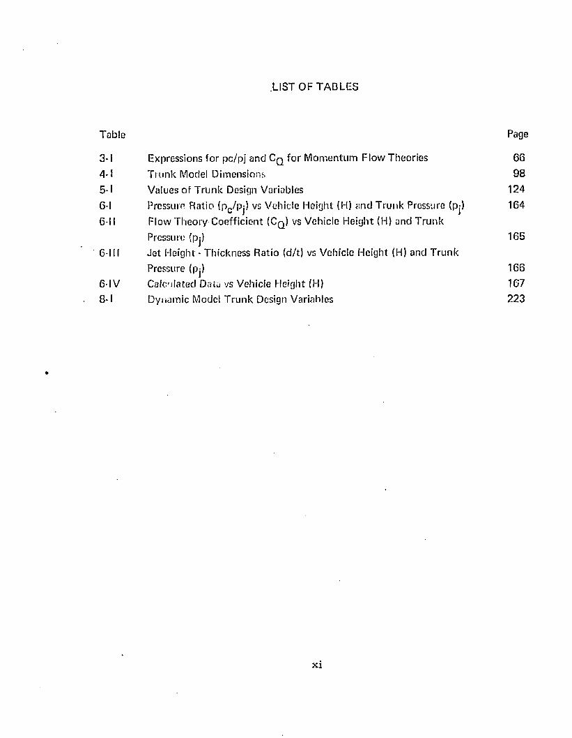
.LIST OF TABLES
Table Page
3-1 Expressions for pc /p j and C q fo r M om entum Flow Theories 6 6
4-1 T ru n k Model Dim ensions 98
5-1 Values of T runk Design Variables 124
6 -I Pressure Ratio (pc /pj) vs Vehicle Height (H) and T runk Pressure (pj) 164
6 -II Flow T heory Coeffic ient (C q ) vs Vehicle Height (H) and T runk
Pressure (pj) 165
6-111 J e t Height - Thickness Ratio (d/t) vs Vehicle Height (H) and T runk
Pressure (pj) 166
6 -IV Calculated Data vs Vehicle Height (H) 167
8 - 1 Dynam ic Model T ru n k Design Variables 223
xi
LIST OF SYMBOLS
Latin le t te rs
p is ton area , f t ^
cush ion area , ft
cu sh io n area u n d e r t ru n k , f t *1
cu sh io n area u n d e r a irc ra f t ha rd s t ru c tu re , ft'*
je t a u g m e n ta t io n ra tio
cross-sectional a rea o f th e t ru n k , f t^
t r u n k f o o tp r in t area , f t *1
x c o o rd in a te o f u p p e r t ru n k a t t a c h m e n t p o in t , ft.
h o r iz o n ta l d is tance b e tw e e n t r u n k a t t a c h m e n t po in ts , f t
to ta l area o f e x h a u s t nozz le fo r fan ca lib ra t io n tes t , ft**
to ta l area o f all o rif ices in t h e t ru n k , f t ^
to ta l area o f all orifices in t h e n th se g m e n t o f t h e t ru n k , f t^
effec tive f low area fo r fan b ack f low , f t ' 1
effec tive f lo w area fo r th e £ 3 s egm en t o f th e t ru n k , ft**
y c o o rd in a te o f u p p e r t r u n k a t t a c h m e n t p o in t , f t
c o e ff ic ie n t of d ischarge fo r p len u m c h a m b e r
p o w e r - j e t h e igh t p a ra m e te r
p o w e r - th ic k n e ss p a ra m e te r
specific h e a t a t c o n s ta n t pressure , B tu / lb ° F
f lo w c o e ff ic ie n t fo r p ressu re d is t r ib u t io n across t h e je ts
f lo w c o e ff ic ie n t fo r p ressu re d is t r ib u t io n across th e n th row o f je ts
p e rc e n t re d u c t io n in f lo w area o f cu sh io n e x h a u s t caused by t r u n k je ts
c o e ff ic ie n t o f d ischarge fo r t h e t ru n k
c o e ff ic ie n t of d ischarge fo r th e t r u n k n th row o f orif ices in th e t r u n k
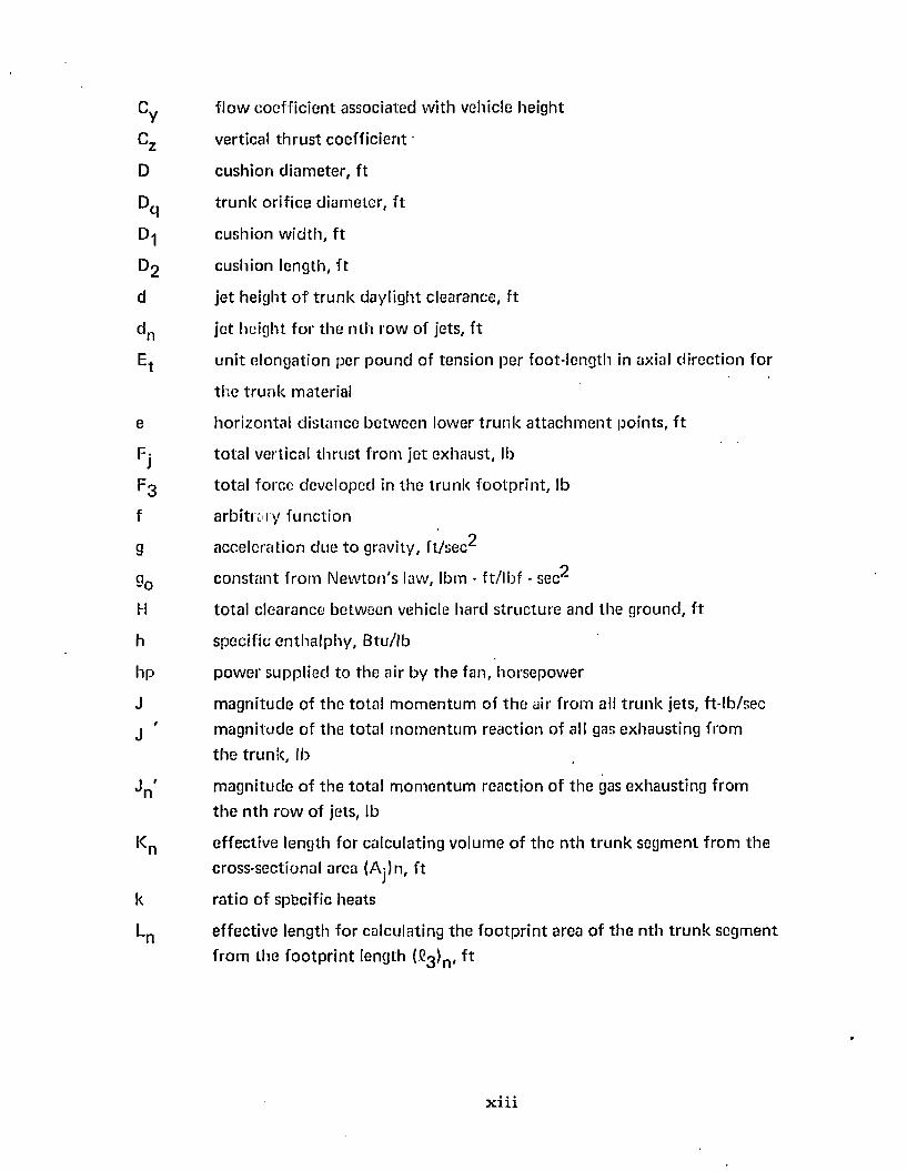
Cy f lo w coe ff ic ien t associated w ith vehicle he ight
Cz vertical th ru s t coeff ic ien t
D cush ion d iam ete r , f t
Dq t ru n k o rif ice d iam ete r , f t
D-| cu sh ion w id th , f t
D2 cu sh ion length , f t
d je t he igh t o f t ru n k day ligh t c learance, f t
d n je t he igh t fo r th e n th row o f jets, f t
Et u n i t e longa tion per p o u n d of ten s ion per foo t- leng th in axial d irec tion fo r
th e t r u n k m aterial
e ho r izon ta l d is tance be tw een lower t r u n k a t ta c h m e n t points , f t
Fj to ta l vertical th ru s t f rom je t exhaust , lb
F 3 to ta l fo rce developed in th e t ru n k fo o tp r in t , lb
f a rb i t ra ry fu n c t io no
g acce le ra tion due to gravity, f t / s e c ' 1
g0 c o n s ta n t f ro m N e w to n 's law, Ibm - f t / lb f - sec^
H to ta l c learance be tw een vehicle hard s tru c tu re and th e g round , f t
h specific e n th a lp h y , B tu / lb
h p p o w e r supp lied to the air by th e fan , ho rsepow er
J m agn itude o f th e to ta l m o m e n tu m o f th e air f rom all t ru n k jets, ft- lb /sec
j ' m agn itude o f th e to ta l m o m e n tu m reac tion of all gas e xhausting f rom
th e t ru n k , lb
J n ' m ag n i tu d e o f th e to ta l m o m e n tu m reac tion o f th e gas exhausting from
th e n th ro w of jets, lb
Kn effective leng th for ca lcu la ting vo lum e of th e n th t ru n k segm en t f rom th e
cross-sectional area (Aj)n, f t
k ra t io o f specific heats
Ln effec tive length fo r ca lcu la ting th e f o o tp r in t area o f th e n th t ru n k segm en t
f ro m th e f o o tp r in t length (£3 ^ , f t
x i i i
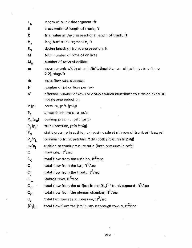
length o f t ru n k side seg m en t , f t
c ross-sectional length o f t ru n k , f t
trial value oi th e c ross-sec tional leng th o f t ru n k , f t
length o f t ru n k se g m e n t n, f t
design length of t r u n k cross-sec tion , f t
to ta l n u m b e r o f row s o f orif ices
n u m b e r o f row s o f orif ices
m ass p e r u n i t w id th oi an infin itesim al elemer. o f gas in jet ;e figure
2 -2 ), s lugs /f t
m ass f lo w rate , slugs/sec
n u m b e r o f je t o rif ices p e r row
effec tive n u m b e r o f row s o r orif ices w hich c o n t r ib u te t o cu sh io n e x h a u s t
nozz le area red u c t io n
pressure , psfa (psfg)
a tm o s p h e r ic pressure, psfa
c ush ion press, r - , psfa (psfg)
t r u n k p ressure , psfa (psfg)
s ta t ic p ressure in cu sh io n e x h a u s t nozzle a t n th ro w of t r u n k orifices, psf
cu sh io n to t r u n k p ressu re ra t io (b o th pressures in psfg)
cu sh io n t o t r u n k pressure ra t io (b o th p ressures in psfg)
f lo w ra te , f t 3 /sec
to ta l f lo w f rom th e c u sh io n , f t 3 /sec
to ta l f lo w f rom th e fan , f t 3 /sec
to ta l f lo w f ro m th e t r u n k , f t 3 /sec
leakage flow , f t 3 /sec
to ta l f lo w f ro m th e o rif ices in t h e (S ) ^ 1 t r u n k segm en t , f t 3 /se c
to ta l f lo w f ro m th e p len u m c h a m b e r , f t 3 /sec
to ta l fan f low a t stall p ressure , f t 3 /sec
to ta l f lo w f ro m th e je ts in ro w n th ro u g h row m, f t 3 /sec
x i v
radius o f cu rv a tu re of je t exhaust , f t
universal gas c o n s ta n t , B tu / lb ° F
radius of cu rv a tu re of n th segm ent, f t
d istance be tw een th e c e n te r of revo lu tion and the cen tro id o f the
cross-sectional area (Aj )n fo r th e n th t ru n k shape, f t
cush ion pe rim ete r , f t
effective length o f jet, f t
e ffective length fo r calculating cushion area Ag from th e length XQ, f t
effective length fo r calculating the vo lum e Vg fro m th e area Ag, f t
effective length fo r calculating th e t ru n k volum e Vj f rom th e area Aj, f t
effective length of th e n th t ru n k segm ent, f t
peripheral d is tance a ro u n d th e t ru n k a t cush ion nozzle exhaust , f t
peripheral d is tance a ro u n d th e t ru n k a t n th row of orifices, f t
abso lu te te m p e ra tu re o f air, ° F
tens ion in th e t ru n k material in the tangen tia l d irec tion per un i t length in
th e axial d irec tio n , lb /f t
th ickness o f periphera l je t nozzle, f t
e ffective th ickness of n th jet, f t
to ta l in ternal energy of the gas in th e c o n tro l vo lum e, Btu
specific in ternal energy of th e gas in th e con tro l vo lum e, B tu /lb
vo lum e o f gas in th e con tro l vo lum e, f t
to ta l cushion vo lum e, f t^
to ta l vo lum e o f d uc ting be tw een fan an d t ru n k , f t^
p o r t io n o f cu sh ion vo lum e d irec tly u n d e r th e t ru n k , f t ^
p o r t io n of cu sh ion vo lum e d irec tly u n d e r th e ha rd s tru c tu re , f t ^
to ta l t r u n k volum e, f t^
ve locity of th e gas, f t /sec
average ve loc ity of th e gas f ro m th e n th row o f t ru n k orifices, f t / sec
(vt )n average ve loc ity o f th e gas f ro m th e cu sh io n e x h a u s t nozzle , a t t h e n th
ro w o f t r u n k orifices, f t / s e c
W m ass o f gas in t h e co n tro l vo lum e, lb
mass o f t h e a irc ra f t , lb
Wj w o rk d o n e b y fan , f t-lb
w mass f lo w o f t h e gas, lb /sec
Wj mass f low in to t h e c o n tro l vo lum e, lb /sec
w n macs f lo w from th e (Cn ) t *1 s e g m e n t o f t h e t ru n k , Ib/scc
w Q m ass f lo w f ro m th e co n tro l vo lum e, lb /sec
X je t th ic k n e ss p a ra m e te r fo r c o n c e n t ra te d jet
X d is tan ce f ro m a irc ra f t e.g. to c e n te r o f pressure o f t r u n k f o o tp r in t , f t
X n je t th ic k n e ss p a ra m e te r fo r n th je t
XQ h o r izo n ta l d is tan ce f ro m inside a t t a c h m e n t p o in t to inside o f t ru n k
fo o tp r in t , f t
x Q x c o o rd in a te o f m in im u m je t he igh t p o in t , f t
YQ t r u n k c learance , vertical d is tance b e tw e e n a irc ra f t hard s t ru c tu re a n d low est
p o in t o f t h e t ru n k , f t
Yoo vertical d is tance a t w h ich n o t r u n k f o o tp r in t ex is ts {C3 = 0 ), f t
y vertical d is tance , f t
y vertical ve loc ity , f t / sec
y vertical a cce le ra tio n , f t / s e c ^
y Q y c o o rd in a te o f m in im u m je t he igh t p o in t , f t
Z n m o m e n tu n p a ra m e te r d e f in ed b y e q u a t io n (5-7)
z d u m m y variable
G reek le t te rs
a’n angle o f revo lu t ion f o r t r u n k cross-sec tion t o fo rm t r u n k vo lu m e se g m e n t n,
rad ians
/?n angu la r p o s it ion o f n th row o f o rif ices rela tive t o th e vertical, rad ians
x v i
angle o f n th orif ice ro w relative t o t ru n k , rad ians
he igh t o f n th orif ice above th e m in im u m g ro u n d c lea rance o f th e t ru n k , f t
s tra in in th e t r u n k m ateria l in /in
p ro p o r t io n a l i ty c o n s ta n t used in ca lcu la ting t r u n k vo lum e
angle th ro u g h w hich th e pe riphera l je t is d e flec ted , rad ians
effec tive je t angle, rad ians
d is tance along th e t ru n k f ro m a t t a c h m e n t p o in t (a, b) t o t h e n th ro w o f
orifices, f t
t ru n k p o ro s i ty
d im ension less ra t io o f t r u n k d im ens ions used in scaling
de ns ity o f th e gas, lb / f t^
cen tra l angle for n th t r u n k segm en t, radians
angle b e tw e e n t r u n k an d g ro u n d a t t h e edge of th e t r u n k fo o tp r in t , rad ians
c o m p le m e n ta ry angle t o radians
S u b sc r ip ts
a irc ra f t
a tm o sp h e re
c ush ion
e n d sec t ion o f t r u n k vo lu m e
fan
cush ion vo lum e u n d e r t r u n k
c u sh io n vo lum e u n d e r ha rd s t ru c tu re
f lo w in to th e c o n tro l vo lum e
t ru n k
c o rn e r sec t io n o f t r u n k vo lu m e
f irs t row o f j e t o rif ices inside t h e cush ion
last ro w o f j e t o r if ices inside th e cush ion
a rb i t ra ry
x v i i
o
pq
r
st0
1
2
3
4
Op
f low o u t o f th e c o n tro l vo lum e
p lenum ch a m b e r
orifices
stall c o n d it io n o f t h e fan
side sec t ion o f t ru n k vo lum e
to ta l value of all parts
a tm o sp h e re
t ru n k segm en t inscribed by angle 0 -j
t ru n k segm en t inscribed by angle 0 2
t r u n k segm ent f la t ten ed against the g round
t ru n k segm en t associa ted w ith th e m in im u m possible value of R-j
d istance a t w hich t ru n k s u p p o r t is negligible (C3 = 0 )
x v i i i
1. INTRODU CTIO N
1.1 S ta te m e n t of th e Problem
T h e purpose o f th is w ork is to develop design techn iques which can predict
analy tica lly the pow er requ irem en ts and dynam ic response of a unique air suspension
system w hich can be used to replace th e landing gear on aircraft. The particular system
analyzed will be referred to as th e Air Cushion Landing System and abbreviated ACLS. The
ACLS was deve loped jo in tly by Bell A erosystem s and the Air Force Flight Dynamics
L abora to ry . It utilizes a flexible skirt or " t r u n k ” and a d is tr ibu ted peripheral je t as
described in Section 1.3. The deve lopm en t program for the ACLS is d o c u m e n ted by
References 1, 2, 3, 4, 5, and 6 . The referenced program was largely experim ental. This s tudy
is in te n d e d to p resen t analytical techn iques which will be useful in ex trapo la ting the
reported experim enta l results and in designing larger and m ore efficient air suspension
system s fo r aircraft.
T he pow er requ irem en ts for an air suspension system m ay be s ta ted in te rm s of
pressure versus flow' characteris tics for th e fan which supplies the air fo r the system . In the
fo llowing chapters , relationships are developed w hich relate the pressure and f low to the
resulting g ro u n d clearance and overpressure beneath the aircraft. For the purposes of this
w ork , th e e ffec t of fo rw ard velocity is neglected.
T h e dynam ic response of in terest in th is work is th e response o f th e air cushion
tru n k to landing im pact. It is desired to p red ic t th e forces and m o tions w hich result from a
residual vertical velocity o f th e a ircraft a t to u ch d o w n . Of particu lar in te rest are the
m ax im u m acceleration and th e m axim um tru n k deflection fo r a given a ircraft weight and
sink rate . F o r th e pu rpose of th is w ork , on ly vertical forces and m o tions are considered.
1
2
A e ro d y n a m ic fo rces resu lting f ro m th e a irc ra f t su rfaces are neg lec ted as are all m o m e n ts an d
angu lar m o tio n s .
S ta t ic ana lyses o f th e t r u n k sh a p e an d f lo w charac te r is t ic s are p re requ is i te s to
ana ly t ica l t r e a tm e n t o f b o th p o w e r r e q u i re m e n ts and th e d y n a m ic response of th e sy s tem .
C o n se q u e n t ly , th e s e analyses a re deve loped a n d ex p e r im e n ta l ly verified p r io r t o p resen ting
th e d y n a m ic a n d p o w e r sy s te m analysis.
T h e m o s t w ide ly a c c e p te d f low th eo r ie s fo r p red ic t in g th e c ush ion p ressu re in air
c u sh io n vehicles are su m m a riz ed in C h a p te r 2. N ond im ens iona l f low p a ra m e te rs are
dev e lo p ed in C h a p te r 3. T h e p red ic tio n o f th e t r u n k shape an d c ro s s se c t io n a l area is
de v e lo p e d in C h a p te r 4. F low th eo r ie s fo r t h e c o m b in e d t ru n k - je t sy s tem are p re se n ted in
C h a p te r 5. E x p e r im en ta l resu lts t o verify t h e t r u n k shape an d f lo w th eo r ies are p re se n ted in
C h a p te r G. A n analysis o f t h e d y n a m ic response o f th e t r u n k sys tem is derived in C h a p te r 7.
E x p e r im en ta l ve rif ica tion o f t h e d y n a m ic sy s tem is p re se n ted in C h a p te r 8 .
A s u m m a ry of the design c o n s id e ra t io n s , th e d y n a m ic response and th e p o w e r
r e q u i re m e n ts is inc luded in C h a p te r 9.
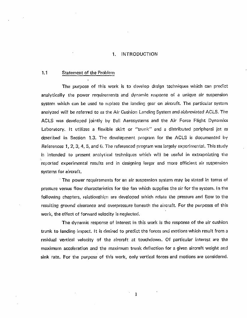
1 .2 B ackg round
A n air su spens ion sy s tem s u p p o r t s a vehicle o n a cu sh io n o f a ir t ra p p e d b e tw e e n
t h e vehic le u n d e rs id e a n d th e g ro u n d . T h e vehicle w e ig h t is u n i fo rm ly d is t r ib u te d by th e air
c u sh io n over a large area. E x tre m e ly low g ro u n d pressure results . C o n se q u e n tly , such a
sy s tem o ffe rs t h e p o ten t ia l f o r o p e ra t in g on e x tre m e ly s o f t g ro u n d an d even w a te r .
T h e t w o m o s t c o m m o n a ir suspens ion sys tem s a re k n o w n as th e p len u m c h a m b e r
a n d th e pe riphera l jet. T hese sys tem s are i l lu s tra ted in F igures 1-1 (a) an d 1-1 (b),
respec tive ly . B o th sy s tem s rely on " g ro u n d e f fe c ts " o r an overpressure caused b y th e
p resen ce o f th e g ro u n d fo r s u p p o r t . In b o th sys tem s, in p u t p o w e r is requ ired t o m ain ta in
t h e a ir c u sh io n . T h e m a jo r d i f fe re n c e b e tw e e n th e tw o sy s te m s lies in th e m echan ism by
w h ich t h e overp ressu re is m a in ta in e d . T h e p le n u m c h a m b e r u til izes a f lo w res tr ic t ion , w hile
th e p e r ip h e ra l je t m a in ta in s t h e overp ressu re b y a m o m e n tu m " se a l" .
7ZZZZZZZ^
P L E N U M C H A M B E R
YZZZZZ/A
P E R I P H E R A L J E T
AI R C U S H I O N S U S P E N S I O N S Y S T E M S
FIGURE T - l
4
In t h e case o f t h e p len u m ch a m b e r , a ir is p u m p e d in to t h e cav ity u n d e r th e
vehicle a n d leaks o u t th ro u g h a n a rro w gap be tw e en th e p e r ip h e ry of t h e vehicle and th e '
g round . A n overpressure is m a in ta ined in th e cavity as a c o n seq u e n c e of equ il ib r ium
be tw e en th e p ressure d iffe ren tia l across t h e gap and th e c o m b in e d acce le ra tion and
f r ic tiona l fo rces w hich l im it th e f low o f a ir th ro u g h th e gap. T h e result is a f lo w res tr ic t ion
o f th e e x h a u s t plane.
In t h e case o f a periphera l jet , a ir is ven ted in a je t a t th e p e r ip h e ry t o fo rm an air
cu r ta in seal. T h e scaling e f fe c t o f th e je t is a c o n seq u e n c e o f th e e q u il ib r ium be tw e en th e
pressure d if fe ren tia l across th e je t and th e cen tr ifugal fo rces in th e cu rved je t a irf low .
Pressure in th e cu sh io n is m a in ta in e d by th is air cu rta in seal. In a " p u r e " pe riphera l je t air
suspension sy s tem , all a ir is in t ro d u c e d a t th e pe r ip h e ry . In th e o ry , a ir n e i th e r e n te rs n o r
leaves t h e cav ity w h en th e sy s tem is a t equ il ib r ium .
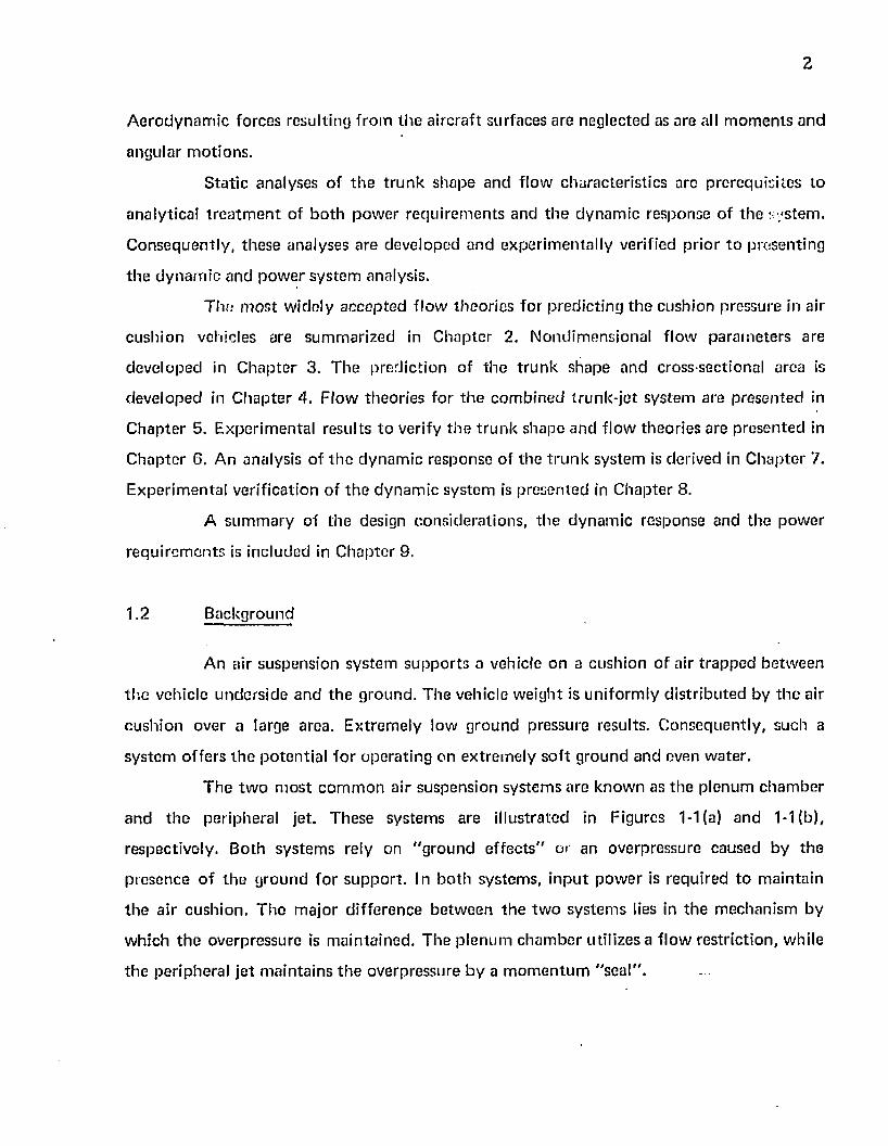
T h e c o n c e p t o f using an air cu sh io n (or g ro u n d effects) to s u p p o r t a n a ircraf t
du ring ta k e -o f f a n d landing is n o t new . M achines w hich u til ize th is p r inc ip le are called
G ro u n d E ffec ts T ak e -o ff and Landing a irc ra f t and are a b b rev ia ted G E T O L a irc ra f t . S tud ies
o f G E T O L c o n c e p ts have been c o n d u c te d by A V R O C anada , O N E R A (F rance ) , UTIAS
(C anada), D O R N IE R (G erm any) and V E R T O L and C O N V A IR , and Bell A e ro sy s te m s in th e
U n ited S ta te s o f A m erica .^*® ) *
Figure 1 -2(a) sh o w s t h e A V R O C A R , a pe riphera l je t c o n c e p t w h ich w as s tud ied
by A V R O b e tw e e n 1954 an d 1 9 6 2 . ( ® ' ^ ' ^ ' ^ J 3 ) Research was d isc o n t in u e d because o f
excessive p o w e r c o n s u m p t io n (a t t r ib u te d to high d u c t Josses) and in s tab il i ty w h e n o u t o f
g ro u n d e ffec t .
F igure 1 -2(b) sh o w s a G E T O L a irc ra f t design p roposed by V E R T O L . T h e
V E R T O L s tu d ie s in d ica ted th a t th e i r design is c o m p e t i t iv e w ith co n v en tio n a l a irc ra f t in
w e igh t a n d p e r f o r m a n c e . ^ ^ '15 ,1 6 ,1 7 ,1 8 ) n oweverf th e s ta t ic and d y n a m ic s tab i l i ty an d
c o n tro l o f t h e c ra f t p resen t m ajo r p rob lem s.
* N u m b e rs in p a ren th eses refer t o references.
( a ) T H E A V R O C A R
(b) V E R T O L P R O P O S E D G E T O L
HISTORICAL GETOL D E S I G N S
FIGURE 1 - 2
6
CONVAIR studied a G ETO L a ircraft w ith a th ick rectangular wing equ ipped with
a peripheral no z z le .^ ® '2 0 ) T he m ajor difficulties an tic ipated were s tability and excessive
energy losses.
O N E R A (^ 1 ,2 2 ) ( jT IA S^23,24 ,25 ,26) ancj d q r j \)[e r (27) |1ave st uc|jocj w ings of
various shapes equ ipped with peripheral nozzles. Each o f the studies m en tioned above
em p loyed a jet he ight (ground clearance) m easurable in feet. Several deficiencies are
associated with such large ground clearances. These deficiencies include poo r stiffness, poor
vertical energy absorptive properties and large pow er requirem ents.
The concep t developed jo in tly by Bell and the Air Force Flight Dynamics
L abora to ry is u n iq u e .^ >2-3,4) | t u t j |jzcs a je t height o f less than one inch, thus reducing the
pow er requ irem ents to an acceptable level. The use of flexible skirts a round the periphery of
th e air cushion greatly increases the stiffness and energy absorptive properties o f the system.
1.3 The ACLS Concept
T he A ir Cushion Landing System com ple te ly eliminates the conventional aircraft
landing gear and replaces it with a cushion of air m ain ta ined beneath the fuselage during
take-off and landing. An artist 's co n c ep t o f the system is show n in Figure 1-3. The elongated
d o u g h n u t show n on th e b o t to m of th e fuselage is called a t runk . The t ru n k fo rm s th e
flexible ducting required to provide a co n tin u o u s curta in of air a round the periphery of th e
fuselage.
Air is fed in to the t ru n k from a com pressor located in the nose wheel well. T he air
is d uc ted by the t ru n k to th e fuselage periphery and exhausted th rough jets in the t ru n k to
fo rm a jet cu rta in . This je t cu rta in seals a pressure of one to tw o psi under th e aircraft
fuselage w hen th e g round is approached . The t runks are m ade of rubber and nylon. When
infla ted , th ey s tre tch approx im ate ly 300% to assume the shape show n in Figure 1-3. When
n o t pressurized, th ey shrink and hug th e fuselage like a de-icing boo t.
A braking system is show n in Figure 1-4, Braking is accom plished by pressing a
brake m aterial against the ground. The brake material m ay be replaced w ith o u t replacing the
ARTI ST' S C O N C E P T OF THE AI R C U S H I O N
L A N D I N G SYSTEM- j
FIGURE 1 - 3
8
FORWARD
S E P A R A T E AIR S U P P L Y MA N I F O LD
INFLATED AIR CUSHION SHOW ING BRAKING PILLOW S
IN FLUSH PO SITIO N
B R A K I N G P i t I O W
FORWARD
C R O S S S E C T I O N S I DE S H O W I N G PI LLOW CO N T AC T
B R A K IN G SYSTEM FOR ACLS
FIGURE 1 - 4
FOOTPRINT PRESSURE DURING ROLL
NTHHUll.f ttftit-LNORMAL FOOTPRINT PRESSURE
DISTRIBUTION
( a ) (b )
ACLS F O O T P R IN T PRESSURE DISTRIBUTION
FIGURE 1 - 5
9
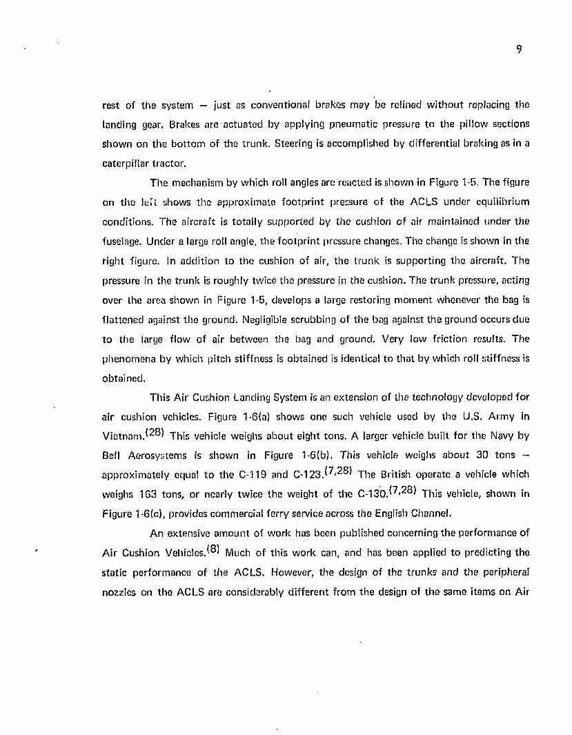
rest of th e system — just as conventional brakes m ay be relined w i th o u t replacing the
landing gear. Brakes are ac tua ted by applying pneum atic pressure to the pillow sections
show n on the b o t to m of th e t ru n k . Steering is accom plished by differential braking as in a
caterp illar tractor.
T he m echanism by w hich roll angles are reacted is shown in Figure 1-5. T he figure
ori th e left shows th e app rox im ate fo o tp r in t pressure of the ACLS under equilibrium
conditions . The a ircraf t is to ta lly sup p o rted by th e cushion o f air m ain ta ined under the
fuselage. U nder a large roll angle, the fo o tp r in t pressure changes. The change is show n in th e
right figure. In add it ion to th e cushion o f air, th e t ru n k is supporting the aircraft. The
pressure in the t ru n k is roughly twice the pressure in the cushion. The tru n k pressure, acting
over the area show n in Figure 1-5, develops a large restoring m o m e n t w henever the bag is
f la t tened against th e ground. Negligible scrubbing of the bag against the ground occurs due
t o th e large flow o f air be tw een the bag and ground. Very low fric tion results. T he
phenom ena by which pitch stiffness is ob ta ined is identical to th a t by w hich roll stiffness is
ob tained .
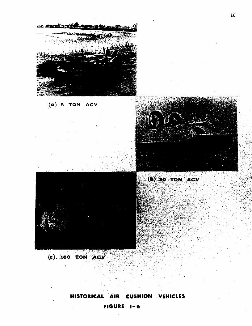
This A ir Cushion Landing System is an ex tension of the technology developed for
air cushion vehicles. Figure 1-6(a) shows one such vehicle used by th e U.S. A rm y in
V ie tn a m .^ 8 ) This vehicle weighs a b o u t e ight tons. A larger vehicle bu ilt fo r the Navy by
Bell A erosystem s is show n in Figure 1 -6 (b). This vehicle weighs a b o u t 30 to n s —
ap p ro x im ate ly equal to the C-119 and C - 1 2 3 .^ '2 8 T he British ope ra te a vehicle which
weighs 163 tons, or nearly tw ice the weight o f th e C -1 3 0 .^ * 2^ This vehicle, show n in
Figure 1-6(c), provides com m ercial ferry service across th e English Channel.
A n extensive a m o u n t of w ork has been published concerning the perfo rm ance of
A ir Cushion V e h i c l e s . ^ Much o f th is w o rk can, and has been applied to predicting th e
s ta t ic perfo rm ance o f th e ACLS. However, th e design o f the t ru n k s and th e peripheral
nozzles on th e ACLS are considerably d iffe ren t f rom th e design of th e sam e item s on Air
' ' ■ ' / ' ' • v ■. N
( a ) 8 T O N A C V
r '
(e) 160 TON Aciy
HISTORICAL AIR C U S H I O N VEHICLES
FIGURE 1 - 6
11
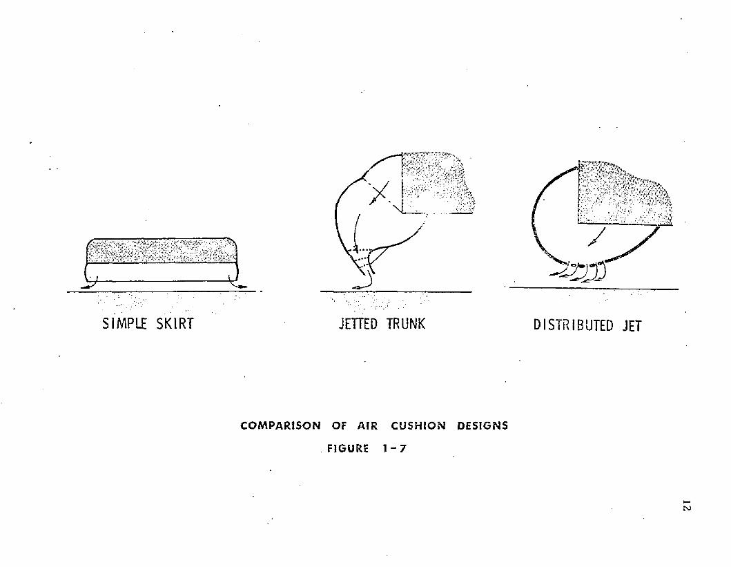
Cushion Vehicles. A com par ison of th e th re e designs is sh o w n in Figure 1-7. T he lefi figure
show s th e cross sec tion of a typ ica l p lenum ch a m b e r w ith a flexible skirt . T he m idd le figure
show s th e cross sec tion o f a typical ACV peripheral je t t ru n k . T he c o n t in u o u s peripheral
nozzle d irec ts th e jet inw ard a t a c o n s ta n t angle. In th e ACLS t ru n k show n on th e right, th e
je t is fo rm ed by m an y holes which d irec t th e je t a t various angles. C onsequen tly , co rrec tions
will be necessary in app ly ing existing f low theo r ies developed fo r s im ple periphera l jets.
These co rrec tions are deve loped in C hap te r 5.
S I M P L E S K I R T JETTED TRUNK D I S T R I B U T E D JET
C O M P A R I S O N OF A I R C U S H I O N D E S I G N S
FIGURE 1 - 7
2. P E R IP H E R A L JE T FLOW RELATIONSHIPS
2.1 M ethod of A pproach to Problem
It is desired to predict the in terre la tionship am ong load capacity , pow er and jet
height for a peripheral jet air suspension system . This p rob lem involves eight independen t
variables w hose values are fixed by th e env ironm ent, th e design, or the m ode o f opera tion .
T here are also eight d e p e n d en t variables of interest. C onsequently , it is necessary to develop
eight independen t equa tions which relate the eight d e p e n d en t variables.
T he variables o f interest and the laws w hich have been applied to develop th e
eight equa tions are sum m arized in Section 2.2. The deve lopm en t of the equa tions requires
the assum ption of a velocity profile across the jet. Several au th o rs have m ade d ifferen t
assum ptions regarding th is velocity profile. These d iffe ren t assum ptions lead to d ifferen t
theories on th e perfo rm ance of the peripheral jet. The basic relationships which are com m on
to all th e theories of in terest are developed in Section 2.3. T he relationships fo r specific
theories are developed in Sections 2 .4 th rough 2.9.
2 .2 Background
T he Air Cushion Landing System is generally similar in design to Air Cushion
Vehicles show n in Figure 1-6. Both em ploy peripheral jets of th e ty p e shown in Figure
1-1 (b). However, there are differences in the design of the t ru n k as show n in Figure 1-7. T he
ACLS uses a d is tr ibu ted je t as com pared w ith a co n cen tra ted je t for the Air Cushion
Vehicles. The single-peripheral jet system will be considered in this section. D istr ibuted jet
system s will be p resen ted in Section 5.
13
14
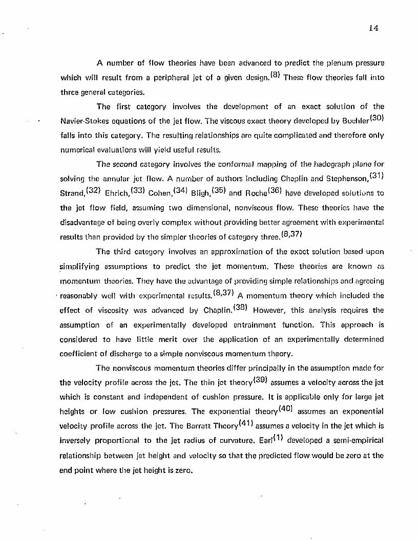
A n u m b e r of f low th eo r ie s have been advanced t o p red ic t th e p lenum pressure
w hich will resu l t f ro m a periphera l je t o f a given d e s i g n . ^ These f low theo r ies fall in to
th re e general categories.
T h e first ca tegory involves th e dev e lo p m en t of an ex a c t so lu t ion o f th e
Navier-Stokes e q u a t io n s o f th e je t flow . T he viscous e x a c t th e o ry deve loped by B o c h l e r ^ )
falls in to th is ca tegory . T he resulting re la tionships are q u i te c o m p lica ted and th e re fo re on ly
num erical eva lua tions will yield useful results.
T h e seco n d ca tego ry involves th e confo rm al m apping o f th e hadograph p lane fo r
solving th e a n n u la r je t flow. A n u m b e r of au th o rs including Chaplin and S tep h en so n ,
S t r a n d , E h r i c h , ^ ^ C o h e n , ^ 4 ) B l i g h / ^ and R o c h e ^ S ) have developed so lu t ions to
th e je t f lo w field, assum ing tw o d im ensional, nonviscous flow. These theo r ies have th e
d isadvan tage o f being overly com plex w i th o u t providing b e t te r ag reem en t w ith experim en ta l
resu lts th a n p rov ided by th e sim pler theo r ies o f ca tegory th re e .{8,37)
T h e th ird ca tegory involves an a p p ro x im a t io n of th e exac t so lu tion based u p o n
sim plify ing assum ptions to p red ic t th e je t m o m e n tu m . These theo r ies are k n o w n as
m o m e n tu m theories . T hey have th e advantage of providing sim ple re la tionships and agreeing
reasonab ly well w ith experim en ta l re su l ts .(8,37) ^ m o m e n tu m th e o ry w hich included th e
e ffec t o f viscosity was advanced by C h a p l i n . H o w e v e r , th is analysis requires th e
a ssu m p tio n of an e x p e r im en ta l ly developed e n tra in m e n t fu n c t io n . This a p p ro ach is
cons ide red t o have little m erit over th e app lica t ion of an experim en ta lly de te rm in e d
c o e ff ic ien t o f d ischarge to a s im ple nonviscous m o m e n tu m th eo ry .
T h e nonviscous m o m e n tu m theo r ies d iffer principally in th e assum ption m ad e fo r
t h e ve loc ity profi le across th e jet. T he th in je t t h e o r y ^ ) assum es a velocity across t h e je t
w hich is c o n s ta n t an d in d e p e n d e n t o f cush ion pressure. It is app licab le on ly fo r large je t
heights o r low cush ion pressures. T he exponen tia l t h e o r y ^ ) assum es an exp o n en tia l
ve loc ity profi le across th e jet. T h e B arra tt T h e o r y ^ ) assum es a ve locity in th e jot w hich is
inversely p ro p o r t io n a l to t h e je t rad ius of cu rva tu re . E a r l^ ^ developed a semi-empirical
re la tionsh ip be tw een je t he igh t and velocity so t h a t th e p red ic ted f lo w w ou ld be zero a t th e
end p o in t w here th e je t he igh t is zero .
15
K h a n z h o n k o r ^ ) a n t j F u m i t a ^ 3 ) d eve loped sep ara te ana lyses fo r su spens ion
sy s tem s w h ich e m p lo y tw o periphera l jets t o p rov ide a " d o u b le sea l" . K h a n z h o n k o r used
th e e x p o n e n t ia l t h e o r y a n d F u m ita used th e th in je t t h e o r y to p re d ic t t h e f lo w a n d p ressu re
ra t io across each jet.
A n u m b e r o f o th e r a u t h o r s ^ * ^ have used th e nonv iscous m o m e n tu m th e o r ie s
t o p re d ic t f lo w p e r fo rm a n c e o f pe riphera l je t a ir suspension system s. T h e m o m e n tu m
th eo r ie s w h ich have been re p o r te d t o give th e b e s t a g re e m e n t w ith te s t resu its a re t h e
E xp o n en tia l T h e o ry and th e B arra tt T h e o r y . (40 ,37 )
In t h e sec t ions t o fo llow , th e m o s t p rev a len t nonv iscous m o m e n tu m th e o r ie s will
be su m m a riz ed . T h e d e v e lo p m e n t o f re la t ionsh ip s w hich are c o m m o n to all o f t h e pe riphera l
je t th eo r ies are p re se n ted in S ec tions 2 .3 a n d 2 .4 . T h e m o m e n tu m th eo r ie s d e v e lo p e d a re as
fo llow s:
T h e T h in J e t T h e o ry — S ec tion 2 .5 ,
T h e E x p o n e n t ia l T h e o ry — S e c tio n 2 .6 ,
T h e B a r ra t t T h e o ry — S ec tion 2 .7 .
T h e S im ple P lenum T h e o ry is p resen ted in S e c t io n 2 .8 . Th is t h e o r y is app licab le
t o t h e ty p e o f a ir suspens ion sy s tem s h o w n in Figure 1*1 (a). T h e p len u m c h a m b e r relies
u p o n f lo w re s t r ic t io n ra th e r th a n a m o m e n tu m seal t o m ain ta in t h e overp ressu re in th e
p lenum .
2 .3 D e v e lo p m e n t o f C o m m o n R e la tionsh ips
2.3.1 A p p ro a c h
In th is sec t io n , th e variab les a ssoc ia ted w ith pe riphera l j e t p e r fo rm a n c e a re listed,
t h e laws w h ich have been app lied a re s ta te d , a n d th e re la t ionsh ip s w h ich a re c o m m o n t o all
t h e pe riphera l j e t th e o r ie s have been deve loped .
16
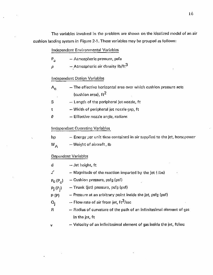
T h e variables involved in th e p rob lem are show n on th e idealized m odel o f an air
cush ion landing system in Figure 2-1. These variables m ay be g rouped as fo llows:
In d ep e n d e n t E nv ironm en ta l Variables
Pa — A tm o sp h e r ic pressure, psfa
p — A tm o sp h e r ic air d e ns ity lb / f t^
In d ep e n d e n t Design Variables
A c — T h e effec tive ho r izon ta l area over w hich cush ion pressure acts
(cushion area), f t^
S — Length o f t h e peripheral je t nozzle, f t
t — W idth o f periphera l je t nozzle gap, f t
0 — Effective nozzle angle, radians
In d ep e n d e n t O pera ting Variables
h p — E nergy per un i t t im e co n ta in ed in air supplied to th e jet, ho rsepow er
W ^ — W eight of a i r c ra f t , lb
D e p e n d e n t Variables
d — J e t he ight, f t
X — M agnitude of th e reac tion im parted by th e je t (-lbs)
p c (Pc ) — Cush ion pressure, psfg (psf)
Pj (Pj) ” T ru n k (jet) pressure, psfg (psf)
P (P) ~ Pressure a t an a rb i t ra ry p o in t inside th e jet, psfg (psf)
Qj — F low ra te o f air f ro m jet, f t^ /se c
R — Radius o f cu rv a tu re o f th e pa th of an infinitesim al e le m en t o f gas
in th e jet, f t
v — V eloc ity of an infin itesim al e le m en t o f gas inside th e je t , f t /sec
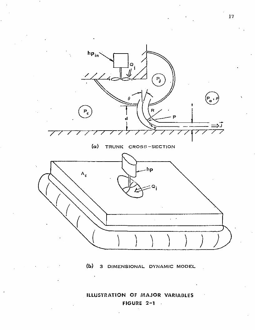
17
( a ) T R U N K C R O S S - S E C T I O N
Q:
( b ) 3 D I M E N S I O N A L DY NAM IC M O D E L
I L L U S T R A T I ON O F M A J O R VARI ABLES
FIGURE 2 - 1
18
T h e in d e p e n d e n t e n v iro n m en ta l variab les are co n s id e red co n s tan ts . F o r a given
design , th e in d e p e n d e n t design variables are f ixed . It is desired to deve lop re la tionsh ips
b e tw e e n th e in d e p e n d e n t op e ra t in g variables an d th e d e p e n d e n t variables fo r f ixed values of
th e in d e p e n d e n t en v iro n m en ta l an d design variables. Such re la tionsh ips w o u ld a llow th e
p red ic t io n o f th e je t h e ig h t as a fu n c t io n o f p o w e r in p u t an d a irc ra f t w eigh t. T he je t he igh t
is a n index o f t h e air cu sh io n p e rfo rm a n c e as is discussed in deta il in C h a p te r 9.
If o n e applies basic laws an d p rincip les to a free b o d y o f th e periphera l je t system ,
t h e necessary re la t ionsh ip s m ay be d eve loped . S ince th e re are e igh t d e p e n d e n t variables, it
will be necessary to deve lop e igh t in d e p e n d e n t re la tionsh ips a m o n g th e variables.
T h e re la t io n sh ip s are as fo llow s:
(a) Fo rce eq u il ib r iu m app lied a t a cross sec t ion of t h e air cu sh io n tak e n
parallel to th e g ro u n d and a t g round level gives:
WA = f ( p c , A c ) (2-1)
(b) C onse rva t ion o f energy involving th e energy source fo r t h e sy s tem
gives:
hp = f (pj, Qj) (2-2)
(c) G e o m e tr ic c o m p a t ib i l i ty be tw e en th e je t radius and th e o th e r
d im e n s io n s gives:
R = f {d, 0 , t) (2-3)
(d) D 'A le m b e r t 's p r inc ip le app lied to an e le m e n t w ith in t h e je t gives:
P = f (p,v, R) (2-4)
(e) C onse rva t ion of energy app lied to t h e je t gives B ernou ll i 's e q u a t io n
Pj = f (P,v, p) (2-5)
19
(f) C onserva t ion o f mass app lied to t h e je t a t its e x i t p lane gives:
Qj » f (v, t ) (2 -6 )
(g) F o rc e eq u il ib r iu m app lied to th e cu sh io n seal gives:
d = f < p c, J (' 0 ) (2-7)
(h) T h e d e f in i t io n oT m o m e n tu m app lied t n th e je t gives:
J ' = f ( S , p j f t) (2-8)
T h e firs t tw o e q u a tio n s (2-1 an d 2-2) p rov ide re la tionsh ips a m o n g th e tw o
in d e p e n d e n t op e ra t in g variab les a n d th re e o f t h e d e p e n d e n t variables. These e q u a t io n s do
n o t involve a s su m p t io n s con cern in g th e f low in th e jet. C o n se q u e n tly , th e y are app licab le to
all of t h e je t f lo w th e o r ie s t o be deve loped later. T h e a p p ro a c h ta k e n here is t o deve lop
th ese tw o re la t ionsh ip s f irs t, t h e n deve lop t h e rem ain ing re la t ionsh ip s based u p o n various
th eo r ies of f lo w in t h e jet.
T h e d e v e lo p m e n t o f th e f irs t tw o re la tionsh ips , w h ich are c o m m o n t o all f low
th e o r ie s fo r th e pe riphera l je t , is p resen ted in S ec t io n s 2 .3 .2 an d 2 .3 .3 .
2 .3 .2 Force E qu il ib r ium
F orce e q u il ib r iu m m ay be app lied to t h e air cu sh io n vehicle a t t h e g round
f o o tp r in t as sh o w n in Figure 1-5{a). T h e fo llow ing a s su m p t io n s are m ad e :
2 .3 .2 .1 T he A C LS is sy m m e tr ic and th e o p p o s i te sides have identical f low ,
s tif fness a n d geom etr ic charac te r is t ics .
2 .3 .2 .2 T h e cente r-o f-g rav ity o f t h e a irc ra f t is d irec tly above th e c e n te r o f th e
a ir cu sh ion .
20
2 .3 .2 .3 T h e pressure is equal to Pc inside th e p lenum and equal to Pa ou ts ide
t h e p lenum .
2 .3 .2 .4 All f low in to th e t ru n k exhausts th ro u g h th e periphera l jet.
2 .3 .2 .5 T h e th ru s t f ro m th e peripheral jet is negligible.
Force equ il ib r ium app lied a t a cross section o f th e air cush ion ta k e n parallel to
th e g round and a t g round level gives:
W A = P C A C (2-9)
2 .3 .3 Conservation of Energy Involving th e Pow er Source
T h e conserva tion of energy law m ay be applied to th e energy supp lied to th e air.
In o rder to app ly th is principle, th e fo llow ing assum ptions are m ade:
2.3.3.1 T h e air is incom pressib le .
2 3 . 3 . 2 T he a ir is inviscid.
2 .3 .3 .3 Energy losses a re negligible.
2 .3 .3 .4 F low is adiabatic .
2 .3 .3 .5 T h e air velocity in th e t ru n k m ay be neglected {Pt = Pj, w here Pt = to ta l
pressure).
T h e w o rk d one on th e air by th e fan m ust p ro d u ce an increase in t h e energy of
th e air.
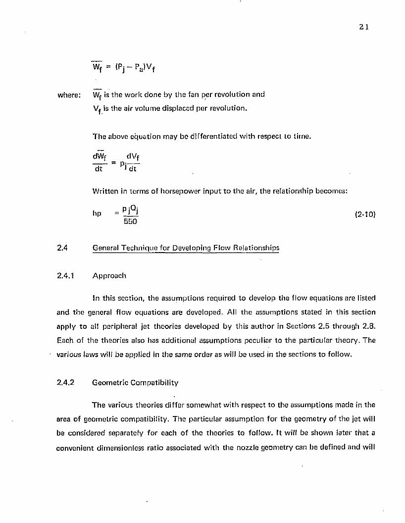
21
Wf = (Pj - Pa )V f
w here : Wf is t h e w o rk d o n e b y th e fan per rev o lu t io n and
Vf is t h e a ir v o lu m e d isp laced p e r revo lu t ion .
T h e above e q u a t io n m ay b e d if fe re n t ia te d w i th respec t to t im e .
dWf _ dV f
d t d t
W rit ten in te rm s o f h o rse p o w e r i n p u t t o t h e air, th e re la t ionsh ip becom es:
i P i ^ ih p = i L i (2 - 1 0 )5 5 0
2.4 G eneral T e c h n iq u e fo r Developing F low R e la tionsh ips
2.4.1 A p p ro a c h
In th is se c t io n , t h e a s su m p t io n s req u ired t o deve lop th e f lo w e q u a t io n s a re listed
a n d t h e general f lo w e q u a t io n s a re deve loped . All t h e a s su m p t io n s s ta te d in th is sec tion
a p p ly t o all pe riphera l je t th e o r ie s deve loped b y th is a u th o r in S ec t io n s 2 .5 th ro u g h 2 .8 .
Each of th e th e o r ie s a lso has ad d it io n a l a s su m p tio n s p ecu lia r to th e p a r t icu la r th e o ry . T he
various laws will b e ap p lied in th e sa m e o rd e r as will be u sed in th e sec t io n s to fo llow .
2 .4 .2 G e o m e tr ic C o m p a tib i l i ty
T h e va rious th e o r ie s d if fe r s o m e w h a t w ith re sp e c t t o th e a s su m p t io n s m ad e in th e
area o f g eo m etr ic c o m p a t ib i l i ty . T h e p a r t icu la r a s su m p tio n f o r th e g e o m e try o f th e je t will
be c o n s id e re d se p a ra te ly fo r each o f t h e th eo r ie s t o fo llow . I t will be sh o w n la te r t h a t a
c o n v e n ie n t d im ens ion less ra t io a ssoc ia ted w ith t h e nozz le g e o m e try can be de f ined an d will
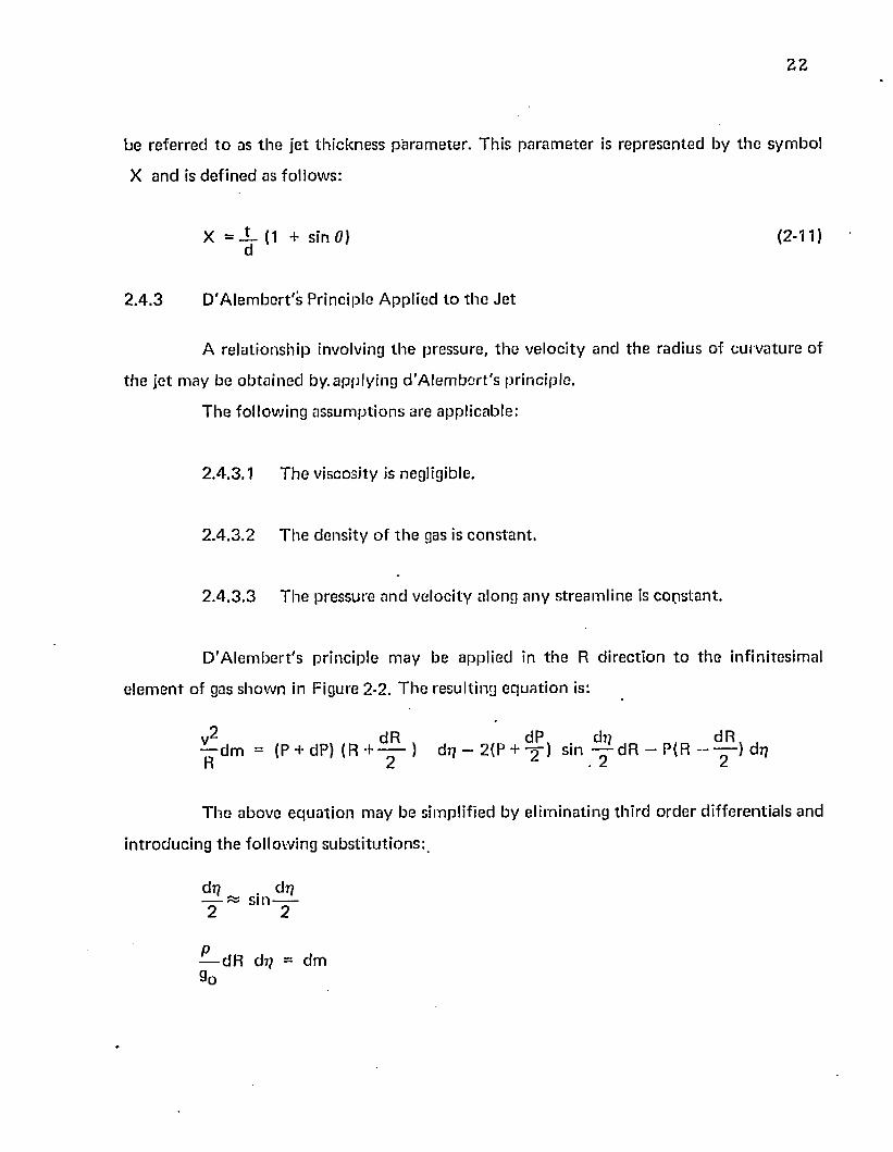
2 2
be re fe rred t o as t h e je t th ic k n e ss p a ra m e te r . Th is p a ra m e te r is rep re sen ted by th e sym bol
X an d is d e f in e d as fo llow s:
X = X (1 + sin 0) (2-11)d
2 .4 .3 D 'A le m b e r t 's P rincip le A pp lied to t h e J e t
A re la t io n sh ip involving th e p ressure , th e ve loc i ty and th e rad ius of cu rv a tu re of
th e je t m ay be o b ta in e d by. a pp ly ing d 'A le m b e r t 's p rinc ip le .
T h e fo llow ing a s su m p tio n s are app licab le :
2 .4 .3 .1 T h e viscosity is negligible.
2 .4 .3 .2 T h e d e n s i ty o f t h e gas is c o n s ta n t .
2 .4 .3 .3 T h e p ressure an d ve loc i ty a long an y s tream line is c o n s ta n t .
D 'A le m b e r t 's p r inc ip le m ay be app lied in t h e R d irec tion t o th e infin itesim al
e le m e n t of gas sh o w n in Figure 2-2. T h e resu lting e q u a t io n is:
— d m = (P + dP) ( R + 4 r > dr? — 2{P + "jj") sin “ dR “ P <R “ d 4 R 2 • 2 2
T h e above e q u a t io n m ay be sim plified by e lim ina ting th ird o rd e r d if fe ren tia ls and
in t ro d u c in g th e fo llow ing su b s t i tu t io n s :
— dR dr? = dm 9o
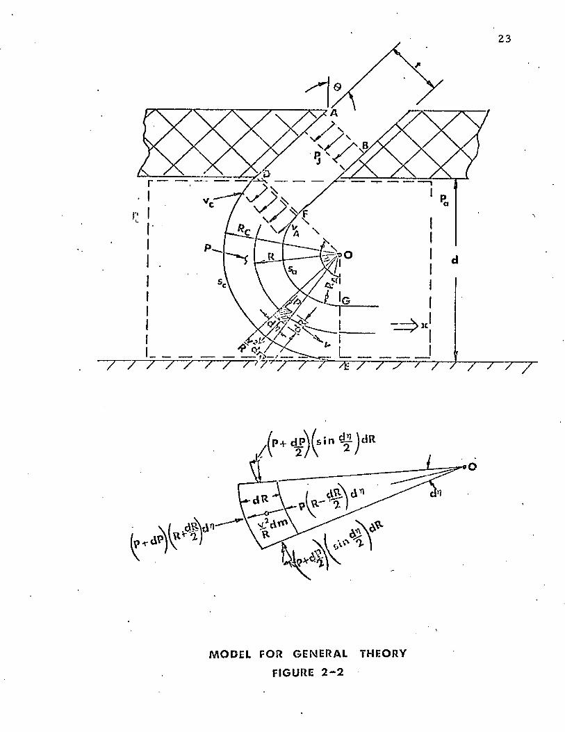
23
M O D E L FOR G E NE RA L THEORY
FIGURE 2 - 2
2 4
T he resulting equa tion becomes:
2pv*dR dp = dP
. 90 R
Since dr/ =£ 0 it is possible to divide by dr/ t o give a simple differential equa tion
which relates th e pressure a t any p o in t in th e jet to th e velocity and the radius of curvature
a t th a t po in t. The eq u a tio n is:
p 9 dR ,dP = ——- v ——— (2-12)
9q r
2.4.4 Conservation-of-Energy Applied to J e t
A rela tionship betw een th e pressure and velocity a t any p o in t in the je t m ay be
ob tained by applying conservation o f energy.
T he following assum ptions are applicable:
2.4.4.1 T he air is incompressible.
2 .4 .4 .2 T h e air is inviscid.
2 .4 .4 .3 Energy losses are negligible.
2 A A A T he f low is adiabatic .
2.4.4.B T he air velocity in th e t ru n k m ay be neglected.
2.4.4.G T he to ta l pressure is everyw here constan t.
2 .4 .4 .7 T he air velocity in th e t ru n k is equal to zero and the pressure Pj = Pt
(w here P^ = to ta l pressure).
25
2 .4 .4 . 8 T he f lo w ve loc i ty is p e rp e n d icu la r to th e e x i t p lane D F.
2 .4 .4 .9 T h e e f fe c t o f change o f he ig h t o f th e gas is negligible.
2 .4 ,4 .1 0 T h e energy a long a n y s tream lin e is c o n s ta n t .
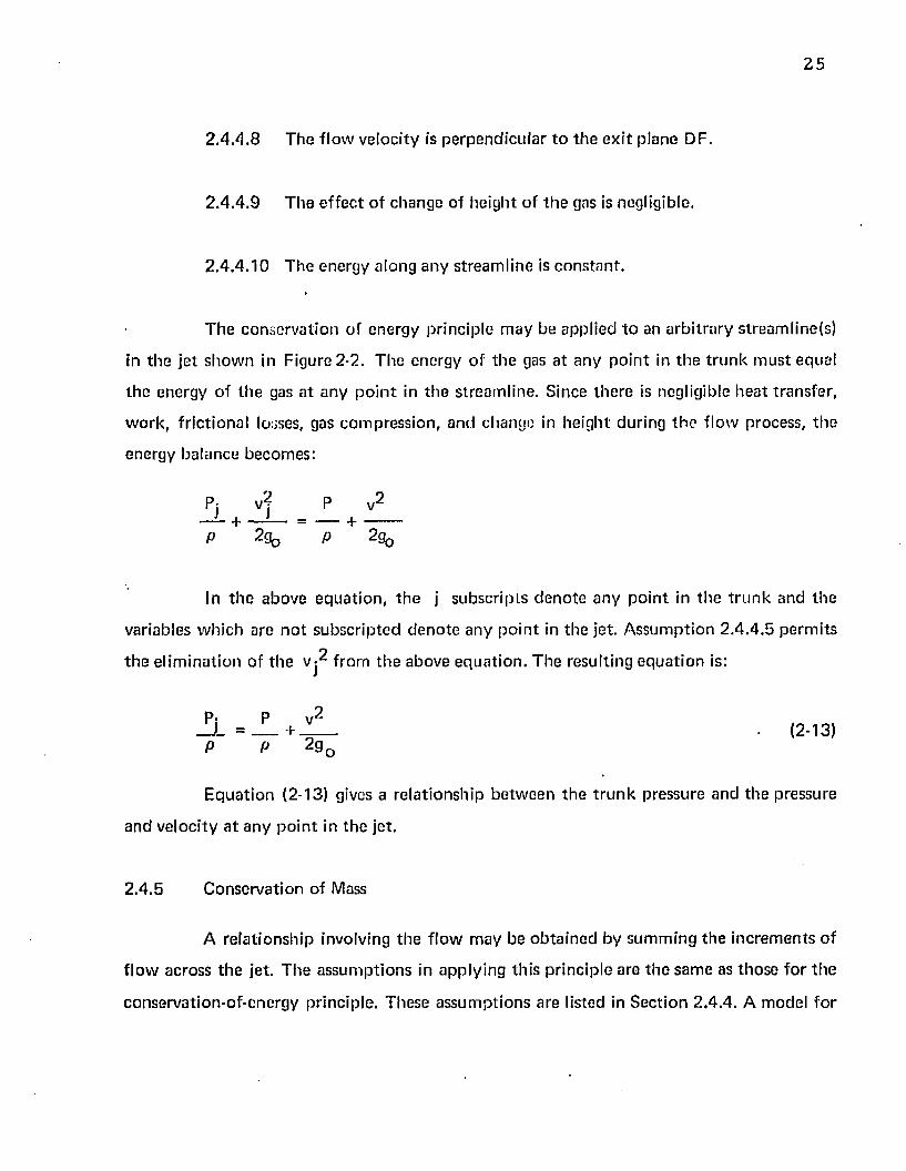
T h e co n se rv a t io n of energy p r inc ip le m ay be app lied to an a rb i t ra ry s tream line(s)
in th e je t s h o w n in F igure 2-2. T h e energy o f t h e gas a t an y p o in t in th e t ru n k m u s t equal
t h e energy o f th e gas a t a n y p o in t in t h e s tream line . S ince th e re is negligible h e a t tran sfe r ,
w o rk , f r ic t io n a l losses, gas co m p ress io n , and change in he igh t during th e f low process, th e
ene rgy ba lance becom es :
P ?-9o P 2%
In t h e above e q u a tio n , t h e j su b sc r ip ts d e n o te an y p o in t in t h e t r u n k and th e
variables w h ich a re n o t su b sc r ip te d d e n o te a n y p o in t in th e jet . A ssu m p tio n 2 .4 .4 .5 p e rm i ts
E q u a t io n (2-13) gives a re la t ionsh ip b e tw e e n th e t r u n k p ressure and th e p ressure
an d v e loc i ty a t an y p o in t in th e jet .
2 .4 .5 C onse rva t ion of Mass
A re la tio n sh ip involving th e f lo w m ay be o b ta in e d b y su m m in g th e in c re m e n ts o f
f lo w across t h e jet. T h e a s su m p t io n s in ap p ly in g th is p r inc ip le are th e sam e as th o se fo r th e
conserva tion -o f-energy princip le . These a s su m p tio n s a re listed in S e c t io n 2 .4 .4 . A m odel fo r
P v 2
+
t h e e l im in a t io n of th e v - 2 f rom th e above e q u a t io n . T h e resulting e q u a t io n is:
P; P v 2_JL = ____+ ____ (2-13)P P 2 g 0
26
th e je t f low is show n in Figure 2-2. F o r an a rb i tra ry value o f rj, th e increm en ts o f f low
across t h e je t m ay be su m m ed in th e radial d irec tion . T he resulting e q u a t io n is:
Rc
y dR (2-14}
In t h e above e q u a tio n , th e in teg ra tion is pe rfo rm ed w ith rj = c o n s ta n t . T he
variable S is th e length of th e je t cu rta in . Equation (2-14) gives th e to ta l f low f rom th e jet,
evaluated a t any angle 7 7 . It is generally conven ien t to evaluate th e f low a t th e e x i t p lane
w here 17 = 9 0 ° + 0.
2 .4 .6 Force Equilibrium A pplied to th e J e t Seal
Force equ il ib r ium m ay be app lied t o th e periphera l je t seal show n in Figure 2-2.
T he assu m p tio n s f rom th e previous sec t ions are re ta ined . The following assum ptions are
ridded:
2.4.6.1 T h e surfaces above a n d be low th e a ir cushion a re rigid and impervious.
2 .4 .6 .2 T he cush ion is in s ta t ic equ il ib r ium (no air en tering or leaving th e
cush ion).
2 .4 .6 .3 T h e cush ion pressure is separa ted f ro m th e a tm o sp h e re by a peripheral
jet.
2 .4 .6 .4 T h e m ixing be tw een th e jet and th e su rro u n d in g en v iro n m en t is
negligible an d th e ve locity profile is c o n s ta n t a long th e length o f th e je t
( tw o d im ensional f low ).
27
2 .4 .6 .5 T h e to ta l m o m e n tu m o f th e j e t a t th e nozz le ex it p lane (Section DF,
F igure 2-2) is equa l in m a g n i tu d e to th e to ta l m o m e n tu m o f th e je t a t
th e cush ion e x i t p lane (S ec t ion EG, Figure 2-2).
U n d er eq u il ib r iu m co n d it io n s , a ir n e i th e r en te rs no r leaves th e cu sh io n (p lenum ).
T h e cush ion p ressu re is m a in ta in ed by th e rea c t io n w hich resu lts f rom th e m o m e n tu m
change in th e pe riphera l jet. Fo r fo rce e q u il ib r ium in th e air gap (d), t h e cu sh io n p ressure
t im es t h e area over w h ich it ac ts m u s t equal t h e t im e ra te o f change o f th e to ta l je t
m o m e n tu m . T h e e q u a t io n expressing fo rc e e q u il ib r iu m across t h e a ir gap in th e d irec tion
p e rp e n d icu la r t o th e air gap ( the x d irec tion ) is:
tu rn o f th e gas m ay be d e te rm in e d by th e m o m e n tu m p rinc ip le app lied to t h e con tro l
vo lum e. T he m o m e n tu m princ ip le m ay be s ta te d :
If th e ve loc ity and f lo w ra te are a ssum ed c o n s ta n t , an d th e g e o m e try o f Figure
2 - 2 is app lied , t h e resu lting e q u a t io n is
pc S d = J L ( J ) Xd t gQ
(2-15)
T he m a g n i tu d e o f th e fo rce in th e x d i re c t io n deve loped by th e change in m om en-
wv x
o u t in
(2-16)
w here
J ' s s ™9o
2 8
2 .4 .7 Pressure V ar ia t io n A cross t h e J e t
T h e p rinc ipal d i f fe re n c e b e tw e e n th e various m o m e n tu m th e o r ie s is a d if fe ren ce
in t h e p ressure varia tion across t h e jet. All th e o r ie s p re s e n te d assum e th e pressure an d
v e loc i ty a long an y s tre a m lin e is c o n s ta n t (A ssu m p tio n 2 .4 .3 .3 J . C o n se q u e n tly , je t p ressu re is
in d e p e n d e n t of 17 in F igures 2-2, 2-3, an d 2-4.
T h e p ressure va ria t ion across th e je t m ay be d e te rm in e d by co m b in in g th e
conserva tion -o f-ene rgy e q u a t io n , E q u a t io n (2-13), a n d th e D 'A le m b e r t 's e q u a t io n , E q u a t io n
(2-12). T h e resu l t is:
d P dR = —2 ------P - P j R
T h e resu l ting d iffe ren tia l e q u a t io n gives t h e p ressure va r ia t ion w ith radius. T h is e q u a t io n
m ay be in te g ra te d b e tw e e n t h e je t b o u n d a ry an d so m e a rb i t ra ry rad ius to give th e p ressure
a t a n y p o in t inside t h e jet.
T h e p ressu re v a r ia t ions fo r t h e th r e e m o m e n tu m th e o r ie s are p re se n ted in
S ec t io n s 2 .5 .7 , 2 .6 .7 , an d 2 .7 .7 .
2 .4 .8 V e loc ity V aria t ion A cross th e J e t
T h e v e loc i ty varia t ion across t h e je t m ay be fo u n d in a s im ilar m a n n e r to th e
p ressu re va ria tion . In th is case, t h e p ressu re te rm s in t h e D 'A le m b e r t 's P rincip le re la t ionsh ip ,
E q u a t io n (2-12), m ay be e l im in a te d by s u b s t i tu t io n of th e conserva tion -o f-energy
re la t ionsh ip , E q u a t io n (2-13). T h e resu l t is:
dv _ d R
“ R
2 9
T h e resulting differentia l equa tion relates the velocity variation to th e radius. T he
equa tion m ay be in tegrated betw een th e je t b ounda ry and som e arb itra ry radius vecto r w ith
term inus inside th e je t to give th e velocity a t any p o in t inside the jet. As a consequence o f
A ssum ption 2 .4 .3 .3 th e velocity in th e je t is in d ep en d en t of 77 in Figures 2-2, 2-3, and 2-4.
T he velocity variations for th e th ree m o m e n tu m theories are presented in Sections
2 .5 .8 , 2 .6 .8 , and 2 .7 .8 . '
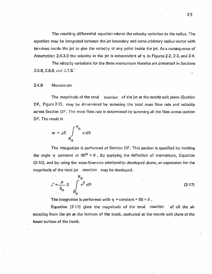
2 .4 .9 M om entum
DF, Figure 2-2), m ay be de te rm ined by sum m ing th e to ta l mass f low rate and velocity
across Section DF. The mass f low rate is de te rm ined by sum m ing all the flow across section
DF. The result is
th e angle 77 c o n s ta n t a t 9 0 ° + 0 . By apply ing th e defin ition o f m om en tu m , Equation
(2 - 1 C), and by using th e mass-flow-rate rela tionship developed above, an expression for th e
m agnitude o f th e to ta l jet reac tion m ay be developed.
T he in tegration is pe rfo rm ed w ith 77 = co n s tan t = 90 + 6 .
E qua tion (2-17) gives th e m agn itude o f th e to ta l reaction o f all th e air
escaping f rom th e jet a t the b o t to m o f th e t ru n k , evaluated a t th e nozzle ex it plane a t the
lower surface o f the t ru n k .
T he m agnitude o f th e to ta l reaction o f th e jet a t th e nozzle ex it plane (Section
v dR
T he in tegration is pe rfo rm ed a t Section DF. Th is section is specified by holding
Rc
(2-17)
3 0
2 .4 .1 0 J e t F low
T h e d i f fe re n t m o m e n tu m th e o r ie s p re d ic t d i f f e re n t f low s as a c o n se q u e n c e o f t h e
d i f fe re n t p ressu re d is t r ib u t io n s assum ed to ex is t ac ross t h e je t . T h e to ta l je t f low , Qj, m ay
be fo u n d by in teg ra t ing E q u a t io n (2-14). T h is in te g ra t io n has been p e rfo rm e d in S ec tio n s
2 .5 .1 0 , 2 .6 .1 0 , an d 2.,7.10. In each se c t io n , t h e final resu l t has been a rranged so t h a t t h e
e xp ress ions fo r th e d i f fe re n t th e o r ie s m ay be c o m p a re d easily. In each case, t h e express ion
f o r f lo w has t h e fo llow ing fo rm :
by th e th re e theo r ies . In la te r s e c t io n s th is t e r m is t r e a te d as a f lo w c o e ff ic ie n t and
d e s igna ted C q .
2.4 .11 R ecovery Pressure R atio
T h e final re la t io n sh ip desired is th e ra t io o f t h e cu sh io n p ressure to t r u n k p ressure
as a fu n c t io n o f th e je t th ic k n e ss p a ra m e te r . T h is re la t io n sh ip has t h e fo rm
w h e re X = t / d (1 + sin 0 ). A se co n d re la t io n sh ip b e tw e e n p c/p j can be deve loped by
c o m b in in g E q u a t io n s (2-9) an d (2-10). T h e resu lt is:
T h e te rm in b racke ts , if a n y , signifies t h e d if fe ren ce be tw een th e f lo w p red ic te d
p c/Pj = f (X)
It ts e v id e n t f ro m th e a b o v e re la t io n sh ip s t h a t p c /p j fo rm s a n im p o r ta n t link in
re la ting t h e in d e p e n d e n t variab les W , a n d hp to t h e resu lting j e t he igh t d .
31
T h e pc/p j = f(X) re la tionsh ips fo r th e th re e m o m e n tu m th eo r ies have been
deve loped in Sec tions 2 .5 .11 , 2 .6 .1 1 , and 2 .7 .11 . T h e re la tionsh ips involving a irc ra f t w eight
(W^), ho rsepow er (hp) and je t he igh t (d) have been deve loped in C hap te r 3.
2 .5 T he T h in J e t T h eo ry
2.5.1 A pproach and A ssum ptions
In Sec tion 2 .3 .2 , E q u a tio n (2-9) was developed w hich rela tes a irc ra f t w e igh t to
cush ion pressure and area
WA = PC A c (2-91
In Sec tion 2 .3 .3 , E q u a tio n (2-10) was deve loped w hich rela tes inpu t pow er to
t r u n k pressure an d ffow.
h o = Pi ° i (2 - 1 0 )5 5 0
It is ev iden t t h a t if a re la tionsh ip be tw e en p c and pj cou ld be d e te rm in ed , an d if
Qj cou ld be expressed in te rm s of p c and pj, t h e n th e a irc ra f t w e igh t and in p u t ho rsepow er
cou ld be d irec tly re la ted .
A n u m b e r of th eo r ie s have been p resen ted in th e l i te ra tu re fo r relating pc and pj.
T h e s im ples t of th ese th eo r ies is t h e th in je t th e o ry w hich is developed in th is section . T he
ob jec tive is to d e te rm in e th e f low Qj an d th e Pc /Pj re la tionsh ip w hich can be used t o link
E q u a tio n s (2-9) and (2-10).
T h e T h in J e t T h e o ry advanced by C h a p l i n ^ 9 ) assum es th a t th e je t he igh t is very
m uch larger th a n th e nozz le th ickness (d > t ) . U nder these c o n d it io n s , th e je t is ex trem e ly
th in an d is cons idered as a single s tream line (see Figure 2-3). In ad d it io n t o th e assum ptions
m ade in Sec tion 2.1, th e fo llow ing res tr ic tions are im posed :
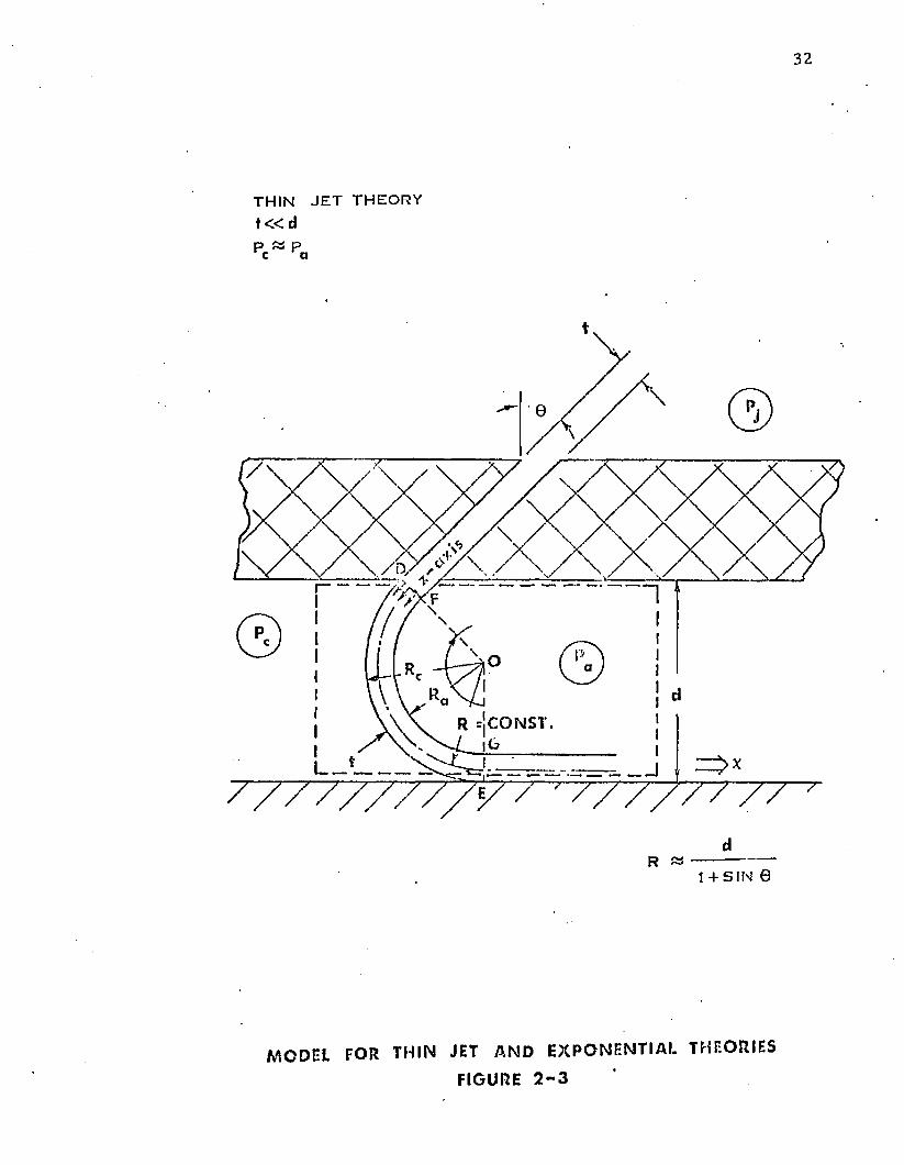
THIN JET THEORY t « d
R = C ONS T.
— > X
dR « ----------------
1 + SIN 0
MODEL FOR THIN JET A N D E X P O N E N T I AL THEORIES
FIGURE 2 - 3
33
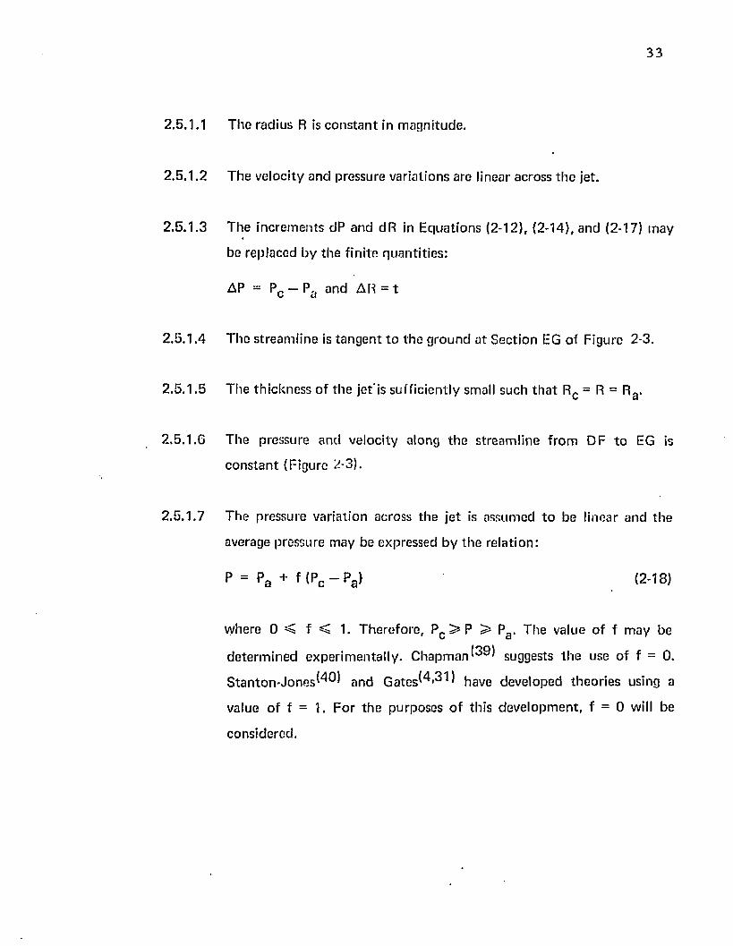
2.5.1.1
2 .5 .1 .2
2 .5 .1 .3
2 .5 .1 .4
2 .5 .1 .5
2 .5 .1 .6
2 .5 .1 .7
T h e rad ius R is c o n s ta n t in m agn itude .
T he ve loc i ty an d p ressu re va ria tions are linear across th e jet.
T h e in c re m e n ts dP and dR in E q u a t io n s (2-12), (2-14), and (2-17) m ay
be rep laced by th e f in ite q u a n ti t ie s :
AP = Pc — Pfl an d AR = t
T he s tre a m lin e is t a n g e n t t o th e g ro u n d a t S ec t io n EG o f F igure 2-3.
T h e th ic k n e ss o f th e j e t i s su ff ic ien tly small su ch t h a t Rc = R = Rg.
T h e p ressure a n d ve loc ity a long th e s tre a m lin e f ro m DF t o EG is
c o n s ta n t (F igure 2-3).
T h e p ressure varia tion across th e je t is assum ed t o be l inear an d th e
average pressure m ay be expressed by th e re la tion :
p = p a + f <pc - pa> (2-18)
w here 0 < f < 1. T h e re fo re , Pc ^ P > Pa . T he value o f f m ay be
d e te rm in e d ex p e r im e n ta l ly . C h a p m a n ^ 9 ) suggests t h e use o f f = 0.
S t a n t o n - J o n e s ^ ^ an d G a t e s ^ ' ^ have deve loped th e o r ie s using a
value o f f = 1. F o r t h e pu rposes o f th is d e v e lo p m e n t , f = 0 will be
cons ide red .
2.5.2 Geometric Compatibility
F ro m F i g u r e 2-3 i t m ay be seen t h a t th e fo llow ing g e o m e tr ic re la t io n sh ip ho lds:
1 + s in 0(2-19}
2 .5 .3 D 'A le m b e r t 's Principle
A s s u m p tio n 2 .5 .1 .3 app lied to th e D 'A le m b e r t 's e q u a t io n , E q u a t io n (2-12), gives:
In t h e above e q u a t io n , b o t h p c a n d v are u n k n o w n q u a n ti t ie s . T h e c a lcu la t io n o f Pc is
d e p e n d e n t u p o n v. In tu rn , v is d e p e n d e n t u p o n P w hich is d e te rm in e d by th e c h o ice o f f
in A s s u m p tio n 2 .5 .1 .7 .
2 .5 .4 C onserva t ion of Energy
C onserva t ion -o f-energy app lied as spec if ied in S e c t io n 2 .4 .4 gives:
2 .5 .5 C o n se rv a t io n of Mass
C onserva tion -o f-m ass ap p lie d as specif ied in S ec t io n 2 .4 .5 to g e th e r w ith
A s s u m p tio n 2 .5 .1 .3 gives:
(2-20 )
(2 -2 1 )
Q: = S t V (2-22)
2 .5 .6 F o rc e E qu il ib r ium
F o rc e eq u il ib r iu m app lied as specif ied in S e c t io n 2 .4 .6 , to g e th e r w ith
A ssu m p tio n s 2 .5 .1 .1 , 2 .5 .1 .4 , 2 .5 .1 .6 , a n d th e G e o m e tr ic C o m p a tib i l i ty A ssu m p tio n ,
E q u a t io n (2-19), gives:
35
pcd S = J '(1 + sin 0) (2-23)
2 .5 .7 Pressure V aria tion
T he pressure, varia tion across th e je t is c o n s ta n t and equal to th e value assum ed in
A ssu m p tio n 2 .5 .1 .7 ,
P = Pa (2-24)
2 .5 .8 V elocity in th e J e t
T h e velocity in th e je t m ay be d e te rm in e d by su b s ti tu t ing the p ressure in th e jet,
E q u a tio n (2-24), in to t h e conservation-of-energy rela tionship , E qua tion (2-21). T he resu lt
is:
v =
V
2 g0
— (Pr) (2-25)P J
2 .5 .9 M o m en tu m
T he reac tion of th e je t m ay be de te rm in e d by co m b in in g E qua tions (2-16),
(2-22), and (2-25). T he resu lt Is:
J ' - 2 S Pj t (2-26)
2 .5 .1 0 J e t F low
T h e f lo w m ay be d e te rm in e d b y com bin ing th e energy an d m ass-conservation
equa tions , E q u a t io n s (2-21) and (2-22), an d app ly ing th e pressure eq u a t io n , E qua tion
(2-24). T h e resu l t is:
Qi * stJ f i r ) <•>!> ,2-27'
2.5.11 Pressure Ratio
T he pressure ratio fo r th e system m ay be o b ta in ed by com bining th e equilibrium
and m o m e n tu m equations , Equations (2-23) and (2-26), and applying the defin ition fo r jet
th ickness param eter, X = t / d (1 + sin 0 ), E quation (2-11). T he result is:
pc /pj = 2 X ' (2-28)
2 .6 The Exponentia l T heory
2.6.1 A pproach and A ssum ptions
T he simplest th e o ry fo r relating p c/Pj to jet geom etry was presented in Section
2.5. In th e p resen t section, a m ore accura te th eo ry has been developed. T he deve lopm en t
presen ted follows th e overall approach o u tl ined in Section 2.4. The objective of this section
is to develop a m ore exact relationship betw een p c and pj so t h a t inpu t horsepow er,
E quation (2-9), and a ircraft weight, E quation (2-10), can be d irectly related.
T he exponen tia l th e o ry was advanced by S t a n t o n - J o n e s . ^ ) In th is th eo ry , th e
pressure variation across th e jet is exponen tia l as show n in E quation (2-37). T he additional
assum ptions are:
2.6.1.1 T he radius R is c o n s ta n t and can be app ro x im ated by Rc .
2 .6 .1 .2 The radius Rc is ta n g e n t t o th e g round a t Section EG o f Figure 2-3.
2 .6 .2 G eom etric C om patib il i ty
T he geom etric com patib ili ty assum ptions are based upon Figure 2-2. It m ay be
seen th a t th e following relationships hold:
37
Rc = Ra + t (2-30)
2 .6 .3 D 'A le m b e r t 's Principle
A ssu m p tio n 2 .3 .3 .1 ap p lie d t o th e D 'A le m b e r t e q u a t io n (2-12) gives:
Pc • Rc
= J l j dR (2-31)
v2 9oRa Jpa • Ra
T h e variab les o f in teg ra t ion in t h e above e q u a t io n m ay be chan g ed to e l im in a te
th e Rc a n d Ra variables. T h e in te g ra t io n is p e r fo rm e d a long th e z ax is (a t S ec t io n DF in
F igure 2-3) b e tw e e n z - o and z=t. By app ly ing th e new d u m m y variable , z, and using
E q u a t io n s (2-29) an d (2-11), t h e R variab le m ay be e lim in a ted f ro m E q u a t io n (2-31). T h e
resu lt is:
pc t
^ “ I dz (2-32)V 9o 1
Pa o
2 .6 .4 C onserva t ion o f Energy
C onserva t ion o f energy app lied as specif ied in S ec tion 2 ,4 ,4 gives:
v 2 = (p. _ p) (2-33)P J
2 .6 .5 C onserva t ion o f Mass
C onserva t ion o f m ass m ay b e app lied by in teg ra t ing th e ve loc ity across t h e z-axis
be tw e en z= o a n d z = t as sh o w n in Figure 2-3.
Qj = S J " vdz (2-34)
o
38
2 .6 .6 Force Equilib rium
Force equ il ib r ium applied as specified in Sec tion 2 .4 .6 , c o m b in e d with
A ssum ptions 2.6 .1 .1 and 2 .6 .1 .2 , gives:
P c S d = J '(1 - I sin 0) (2-35}
2.6 .7 Pressure V aria tion
T h e velocity re la tionsh ip , E qua tion (2-33), su b s t i tu te d in to th e D 'A lem bert
e q u a t io n (2-32) be tw een th e o u te r b o u n d a ry and som e a rb i tra ry p o in t (z) inside th e je t
gives:
—2X z /t ,p = Pj (1 - e ) (2-36)
w here X is defined by E qua tion (2-11).
2 .6 .8 V eloc ity in th e J e t
T h e velocity in th e je t m ay be de te rm in e d b y solving th e p ressure varia tion.
E qua tion (2-36), w ith t h e energy eq u a tio n , E qua tion (2-33). T he resu l t is:
v = pj (e z / t l ) . (2-37)
2 .6 .9 M o m en tu m
T h e to ta l reac tion of. th e je t m ay be de te rm in e d by E q u a tio n (2-17).
J ' - p —- [ v2 dz 9o
3 9
S u b s t i tu t in g in E q u a tio n (2-37) a n d in teg ra ting gives:
(2-38)J ' = 2 t S p j
2 .6 .1 0 J e t F low
T h e je t f lo w m ay be d e te rm in e d b y com bin ing th e ve loc ity re la tionsh ip , E q u a t io n
(2-37), w i th th e c o n se rv a t io n of m ass e q u a t io n , E q u a t io n (2-34), and in tegra ting . T h e resu lt
is:
Q = t S ( P j ) 1 [ ( 1 „ e - X ) 3 (2 . 3 9 )P x
2.6 .11 Pressure R a tio
T h e p ressure ra t io m ay be d e te rm in e d f ro m th e fo rce equ il ib r ium re la tionsh ip ,
E q u a t io n (2-35), c o m b in e d w ith th e m o m e n tu m re la tionsh ip , E q u a t io n s (2-38) an d (2-11).
T h e resu lt is:
pc /p j = 1 —e“ 2X (2-40)
2.7 T h e B a r ra t t T h e o ry
2.7.1 A p p ro a c h a n d A ssu m p tio n s
T h e B a r ra t t t h e o r y has been re p o r te d to p rov ide q u i te a c c u ra te p red ic t io n s o f th e
p e rfo rm a n c e o f a pe riphera l j e t . (40 ,37 ) j n t |1 js sec t jo n , th e je t f lo w an d recovery p ressure
r a t io p red ic te d by t h e B a rra t t t h e o ry have been d eve loped . T hese p a ra m e te rs a re re la ted to
a irc ra f t w e ig h t an d h o rse p o w e r in C h a p te r 3 .
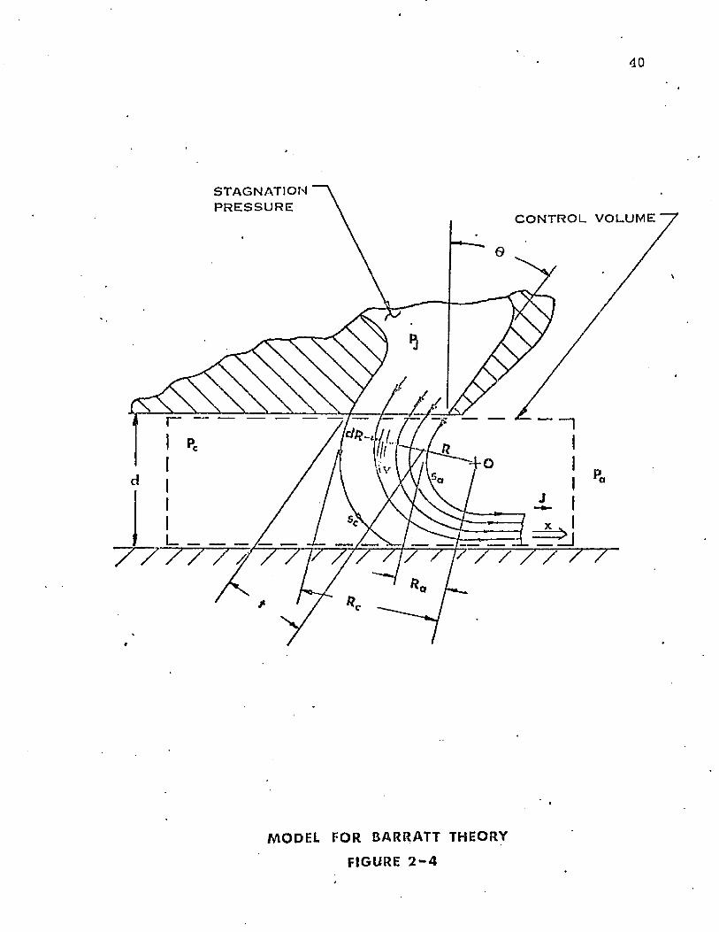
40
ST AGNATIONP R E S S U R E
C O N T R O L VOLUME
MODEL TOR BARRATT THEORY
FIGURE 2 - 4
41
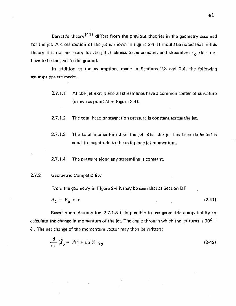
B a r ra t t 's t h e o r y d i f f e r s f ro m th e p rev ious th eo r ie s in th e g e o m e try a ssum ed
fo r t h e je t . A cross sec t ion o f th e je t is s h o w n in F igure 2-4. It sh ou ld be n o te d t h a t in th is
t h e o r y it is n o t necessary fo r th e je t th ic k n e ss t o be c o n s ta n t an d s tream line , sc , d o e s n o t
have t o be ta n g e n t t o th e g round .
In a d d i t io n t o th e a ssu m p tio n s m ad e in S ec tio n s 2 .3 and 2 .4 , t h e fo llow ing
a s su m p tio n s are m ade : •
2 .7 .1 .1 A t th e je t e x i t p lan e all s tream lin es have a c o m m o n c e n te r of c u rv a tu re
(show n as p o in t M in F igure 2-4).
2 .7 .1 .2 T h e to ta l head o r s ta g n a t io n p ressure is c o n s ta n t across th e jet.
2 .7 .1 .3 T h e to ta l m o m e n tu m J o f t h e je t a f te r t h e je t has been de f le c te d is
equal in m ag n i tu d e to th e e x i t p lane je t m o m e n tu m .
2 .7 .1 .4 T h e pressure along an y s tream lin e is c o n s ta n t .
2 .7 .2 G e o m e tr ic C o m p a tib i l i ty
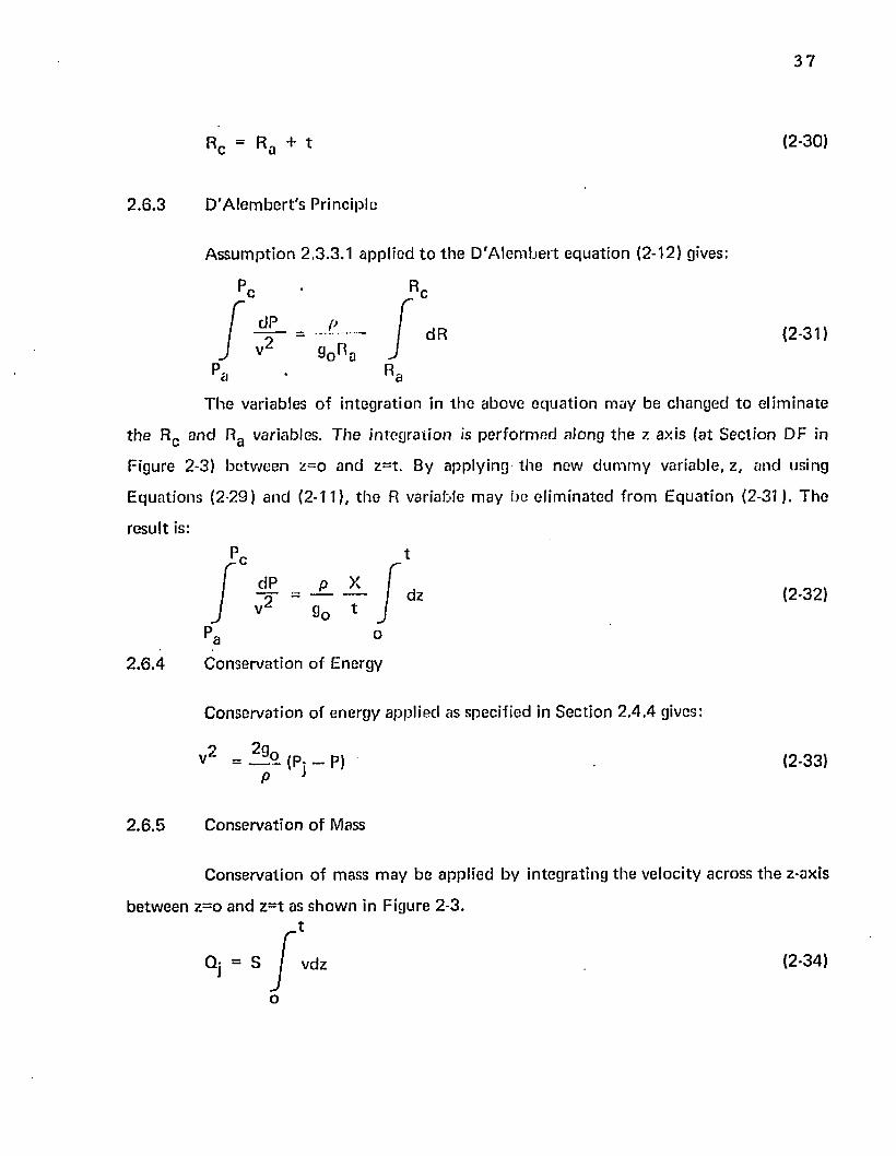
F ro m th e g e o m e try in Figure 2-4 ft m ay be seen t h a t a t S ec tion DF
R c = Ra + t (2-41)
Based u p o n A ssu m p tio n 2 .7 .1 .3 it is possib le t o use g eo m etr ic c o m p a t ib i l i ty to
ca lcu la te t h e change in m o m e n tu m o f t h e jet. T h e angle th ro u g h w hich th e j e t tu rn s is 9 0 ° +
0 . T h e n e t change o f t h e m o m e n tu m vec to r m ay th e n be w r i t t e n :
- ^ - ( J ) x = J ' d + s t n O ) g0 (2-42)
42
2 .7 .3 D 'A lem bert 's Principle
D 'A lem b ert 's Principle applied as specified in S ec tion 2 .4 .3 gives:
dP = pv/2 (2-43)dR R g0
2 .7 .4 C onservation o f Energy
T h e conservation-of-energy princip le applied as specified in Sec tion 2 .4 .4 gives:
p v 2p = P + JL (2-44)
* 2 9o
In o rder to d e te rm in e th e velocity varia tion across th e je t , i t is desired to replace
d P /d R in E qua tion (2-43) w ith an expression fo r d v / d R .T h e needed expression m ay be
derived by d iffe ren tia t ing th e energy eq u a tio n (2-44) w ith respect to R and apply ing
A ssu m p tio n 2 .7 .1 .2 .
OP P dv= - v (2-45)
a R 90 dR
E qua tions (2-45) and (2-43) have been c o m b in e d in E quation (2-51).
2 .7 .5 C onservation o f Mass
T he conservation-of-m ass principle app lied as specified in Section 2 .4 .5 gives:
f RcQj = S / v dR (2-46)
R=,
43
2 .7 .6 Force Equilibrium
Force equilibrium applied as specified in Section 2 .4 .6 in con junc t ion w ith the
geom etric com patib i l i ty rela tionship developed in Equation (2-4.1) gives:
pc S d = J '(1 + sin 0) (2-47)
2 .7 .7 Pressure Variation
T he pressure variation m ay be fou n d by solving th e D 'A lem bert equa tion (2-43)
fo r v2 and substi tu ting it in the conservation o f energy equa tion (2-44). The result is:
dP (2-48)P - P j I R
A t th e inside to je t bo u n d a ry (stream line sc )
P = P„
R = Rc
By in tegrating Equation (2-48) and applying the b o u n d a ry cond it ion to evaluate
th e co n s ta n t th e fo llowing equa tion is ob ta ined :
\2P a p. + ( P c ~ Pi> <2 ' 4 9 >R / c J
A t th e outside of th e jet bo u n d a ry (stream line sa),
P = P r r a
R = Ra
v = va
44
E q u a tio n (2-49) evaluated a t th e ou ts ide b o u n d a ry gives:
~ V 1 - p ° / p i" ( 2 - 5 0 )
2 .7 .8 V elocity V aria tion
T h e velocity varia tion m ay be d e te rm in e d b y equa ting th e D 'A lem b ert and th e
energy e q u a tio n s as fo rm u la ted in E qua tions (2-43) and (2-45) respectively. T h e resu lt is:
dv / dR- = - / — (2-51)v / R
A t th e ou ts ide je t b o u n d a ry (stream line sa )
R - R,‘a
v - va
P = Pr r a
By in tegrating E q u a tio n (2-51) and app ly ing th e b o u n d a ry co n d it io n s , th e
fo llowing e q u a tio n results:
Rav = i v a
R 3
vg m ay be expressed in te rm s o f Pj by app ly ing v = vg w h e re P - Pa , in th e
conserva tion o f energy eq u a tio n (2-44). T h e resu lt is:
2g0
45
T h e last e q u a t io n m ay b e s u b s t i tu te d in to t h e general ve loc ity e q u a t io n to y ie ld :
v _ R a / 2 90 D.P: (2-52)R V p
2 .7 .9 M o m e n tu m
T h e to ta l reac tion o f t h e je t m ay be deter m ined by su b s t i tu t in g th e value o f v
given b y E q u a t io n (2-52) in t h e m o m e n tu m e q u a t io n , E q u a t io n (2-17), an d in tegrating
b e tw e e n th e lim its Rg and Rc . T h e resu lting e q u a t io n is:
Rc
J ' = 2 S ( R , ) 2 p: / (2-53)i RIn teg ra t ion gives:
J ' = 2 S p: Ra ( Rc ~ Ra >
Rc
E q u a t io n s (2-41) a n d (2-50) app lied to t h e above re la t ionsh ip give:
J ' = 2 S pj t ^ 1 - p c / Pj (2-54)
2 .7 .1 0 J e t F low
J e t f lo w m ay b e d e te rm in e d b y s u b s t i tu t in g th e v e loc i ty e q u a t io n (2-52) in the
co n se rv a t io n of mass e q u a t io n (2-46). T h e resu lting e q u a t io n is:
Qj = SRa / ? § ° . ( P j ) I _ (2-55)
C'a
In teg ra t ing and a pp ly ing E q u a t io n s (2-41) a n d (2-50) gives:
4 6
~ „ f e yQ V 1 - P r /P iQj “ tS / ------- <p j> ------------------------ ■ log (1 — Pc /Pj) (2-56)
V P 1 - V 1 - Pc/ p j 6 J
2 .7 .11 Pressure R atio
T h e pressure ra t io m ay be d e te rm in e d b y su b s t i tu t in g th e m o m e n tu m eq u a tio n ,
E q u a t io n (2-54), in t h e fo rce e q u il ib r ium e q u a t io n , E q u a t io n (2-47), an d a pp ly ing th e
d e f in i t io n fo r je t th ickness pa ra m e te r , E q u a t io n (2-11), t o s im plify . T h e resu lt is:
pc / Pj = 2X V x 2 + 1 - X (2-57)
2 .8 P lenum T h e o ry
2.8.1 A p p ro a c h an d A ssu m p tio n s
T h e re la t ionsh ip s deve loped in S ec tions 2 .4 , 2 .5 , 2 .6 , and 2.7 app ly on ly to a
periphera l je t and n o t t o a p len u m c h a m b e r . In th is sec t ion , th e e q u a t io n s fo r p red ic ting th e
ho rsepow er , f low an d je t he igh t fo r a p len u m c h a m b e r have been deve loped .
T h e p len u m c h a m b e r d iffe rs f ro m th e periphera l je t as m ay be observed by
c o m p a r in g Figures 1-1 (a) and 1-1 (b). In t h e p len u m c h a m b e r design, th e air Is b low n
d irec tly in to th e p len u m (cushion) r a th e r th a n in to th e t ru n k . C o n se q u e n tly , t h e p len u m
c h a m b e r has n o t r u n k pressure , no pe riphera l jet, a n d n o m o m e n tu m seal. T h e cush ion
p ressu re is m a in ta in e d b y th e f low res tr ic t ion im posed by th e a ir gap b e tw e en th e vehicle
sk ir t an d th e g round . T h e re la t ionsh ip s fo r th is sy s tem m ay be deve loped by conserva tion of
energy ap p lied t o th e e x i t an d b y conserva tion -o f-m ass app lied to t h e a ir f low ing from th e
p o w e r sou rce . T h e a s su m p tio n s m ad e in S ec t io n 2 .3 app ly , b u t th o se m ad e in S ec tions 2 .4 ,
2 .5 , 2 .6 , a n d 2 .7 d o n o t ap p ly .
T h e add it io n a l a s su m p tio n s requ ired are:
2 ,8 .1 .1 T h e air is incom pressib le .
47
2 .8 .1 .2 T h e a ir is inviscid.
2 .8 .1 .3 E nergy losses a re negligible.
2 .8 .1 .4 T h e f low is ad iaba tic .
2 .8 .1 .5 T h e a ir ve loc ity in th e cush ion m ay b e neg lec ted (p t = p c , w here p t =
to ta l p ressure) .
2 .8 .1 .6 T h e to ta l p ressure is eve ryw here c o n s ta n t .
2 .8 .1 .7 T h e f lo w ve loc ity a t t h e e x i t is tw o d im ensiona l a n d p e rp e n d icu la r to
t h e e x i t p lane.
2 .8 .2 C onservation -o f-E nergy A pp lied t o E x h a u s t E x it Plane
T h e conserva tion -o f-energy e q u a t io n m ay be w r i t te n :
P. = P . + — v2 (2-58)C 3 20o
E q u a t io n (2-58) exp resses th e cu sh io n p ressu re in te rm s o f p ressu re a n d ve loc ity
o f th e e x h a u s t a ir w hich has e x p a n d e d t o a tm o s p h e r ic pressure.
2 .8 .3 C onserva t ion o f Mass
C onservation -o f-m ass app lied t o t h e e x h a u s t e x i t gives:
Q P = vp d P S P Cd (2-59)
48
w here th e subscr ip t p refers t o th e p lenum .
E qua tion (2-59) expresses th e to ia l f low from th e p lenum ch a m b e r in te rm s o f
th e effective f low area and th e velocity o f th e gas crossing th e flow area.
2 .8 .4 Conservation-of-Energy Involving th e Pow er System
Using a d e v e lo p m en t similar to th a t given in S ec tion 2 .3 .1 , t h e ho rsepow er
delivered t o th e plerium is:
2 .8 .5 D e te rm ina t ion of F low
Flow from th e p len u m m ay be ob ta in ed by com bin ing E qua tions (2-58) and
(2-59). T he resu lt is:
E q u a tio n (2-C1) gives th e to ta l f low fro m th e p lenum in te rm s o f th e cush ion
pressure an d th e effective flow area.
2 .8 .6 H orsepow er R ela tionship
T he ho rsepow er in p u t can be de te rm in e d f rom E qua tions (2-61) and (2-60). T h e
resu lt is:
E q u a tio n (2-62) gives th e to ta l ho rsepow er w hich m u s t be supp lied to th e a ir in
te rm s o f t h e cush ion pressure and th e effective f lo w area.
(2-61)
(2-62)
3. COMPARISON OF FLOW THEORIES
3.1 I ntroduction
hi o rd e r t o m a k e a general c o m p a r is o n -o f t h e p e rfo rm a n c e p re d ic te d by th e f lo w
th eo r ie s deve loped in C h a p te r 2, it is necessary to deve lop six n o n d im e n s io n a l pa ram ete rs .
T h re e o f th ese p a ra m e te rs are w ide ly used in t h e l i te ra tu re o f A ir C ush ion V ehicles. T hese
p a ra m e te rs inc lude :
(1) A p th e jet a u g m e n ta t io n ra t io is d e f in ed as fo llow s:
to ta l vehicle lift fo rce ^ ^
I re fe rence fo rce
A n u m b e r o f d i f f e re n t re fe rence fo rces are used in th e l i t e r a t u r e . ^ In th is
c h a p te r , t h e re fe rence fo rce is t h e th ru s t w hich cou ld be g e n e ra ted if th e e x h a u s t w ere
d ischarged ve rt ica lly d o w n w a rd . T h e a u g m e n ta t io n ra t io is d iscussed in S e c t io n 3 .7 ,
(2) Pc/Pj* ^ e recovery p ressu re ra t io is d e f in e d as fo llow s:
cu sh io n pressure (gage)P p / P i --------------:------------------------- ;----------- r - *3 ' 2 'u J t r u n k pressure (gage)
T h e recovery p ressu re ra t io is d iscussed in S ec tion 3 .2 .
(3) X, t h e nozzle th ic k n e ss p a ra m e te r w hich w as d e f in e d in S e c t io n 2 .4 .2 as
fo llow s:
X = J l (1 + sin 0) (2-11)d
49
50
T h e nozzle th ickness pa ram eter is discussed in Section 3.3.
Three additional param eters n o t fo u n d in th e l itera ture are also defined in this
chapter. These param eters include:
( 1 ) C q , th e cushion pressure coeff ic ien t is a f low coeff ic ien t . This
pa ram ete r is developed in Section 3.4.
(2) Cj1t, th e pow er-th ickness param eter, is a dimensionless pa ram ete r useful
in predicting pow er requ irem en ts fo r a peripheral jet. This pa ram ete r is
developed in Section 3.5.
(3) C ^ , th e pow er-height param eter, is a dimensionless pa ram ete r useful in
de term in ing the m in im um pow er fo r a required jet height. This
pa ram ete r is developed in Section 3.6.
3 .2 Recovery Pressure Ratio
The ratio of cushion pressure to t ru n k pressure is know n as th e recovery pressure
ratio. It has been show n previously (Section 2.3.2) th a t th e value of pc m ay be de te rm ined
by th e a ircraft weight and th e cushion area. T he value of pj is d e p e n d en t upon th e input
power, th e je t area, the jet height, and th e jet angle. Consequen tly , th e ratio o f p c/p j gives
an im p o r ta n t dimensionless q u a n ti ty w hich is d e p e n d en t on all th e m ajor variables. In
add it ion , it will be show n in C hap ter 4 th a t th e t ru n k shape and stiffness are strongly
influenced by pc/pj.
Because of th e fea tu res c ited above, p c/pj was selected as th e s tandard d e p e n d en t
variable against which o th e r dim ensionless pa ram eters have been p lo tted .
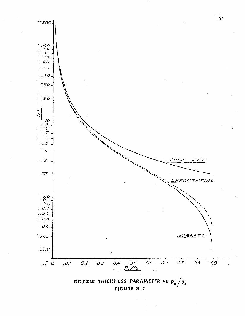
■~S '0 0
BO -— r o .
*f o .
7'H/AJ
£~X PO/7E,\> T M jL
T B A P R A T T
0.8. 0.90.6 AO~ 0 O.I.. : P c / G r
N O Z Z L E T H I C K N E S S P A RAME T E R v s Pc/ p j FIGURE 3 - 1
52
3.3 Nozzle Thickness Param eter
T he nozzle th ickness pa ram ete r was defined in Section 2.4 .2 as follows:
X = - t (1 - fs inO)d
(2-11)
This pa ram ete r relates nozzle geom etry to jet height. For a given design, the
nozzle th ickness (t) and th e jet angle ( 0 ) are relatively constan t. E quation (2-11) shows th a t
the je t height (d) and th e pa ram eter (X) are inversely related. C onsequently , the nozzle
th ickness is valuable in showing the in terrela tionship betw een th e independen t variables and
th e je t height. This in terre la tionship has been show n by graphs o f various nondim ensional
param eters p lo tted against th e d e p e n d en t variable p c /pj.
G raphs of 1/X versus pc/pj for the th ree flow theories are presented in Figure 3-1.
T he analytical re la tionships betw een (pc/pj) and X are show n in Table 3-I.
3.4 Pressure Coeffic ient
T he pressure coeffic ien t, Cq, is, in fact, a flow coeffic ient which is dependen t
upon th e recovery pressure ratio (pc/pj). This coeffic ient has been developed in th is section.
Consider th e to ta l flow from th e je t a t th e nozzle ex it plane as show n by Section
DF in Figure 2-2. T he pressure on th e cushion side o f th e jet is higher th an the pressure on
th e a tm ospheric side o f th e jet. Consequen tly , a velocity and a flow gradient m ay exist
across th e th ickness of the jet. It is th e na tu re o f the assum ed pressure grad ien t across th e je t
th ickness w hich gives rise to th e d ifferences betw een th e th ree m o m e n tu m theories. In
Sections 2 .5 .10 , 2 .6 .10 , and 2 .7 .10 , expressions have been developed fo r th e to ta l flow from
th e je t as p red ic ted by th e th ree m o m e n tu m theories. T he resulting equa tions are:
Th in jet th eo ry
(2-27)
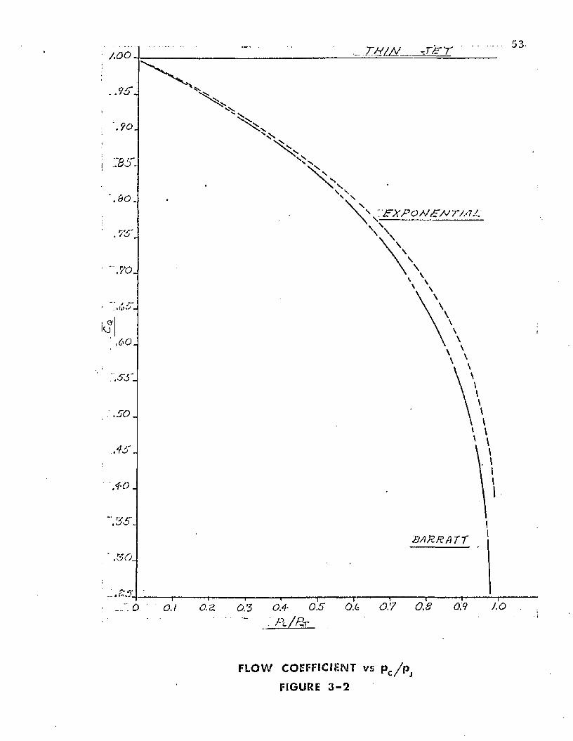
53-. t m / a j -x / = t■ AOO
: p x p o a 'P aj r / . n p
0.5 0.4 0.5 0 . 6 0.7 0.8 0.9
" ■ P ‘ / K r
J.O0.1
F L O W COEFFICIENT v s p c / p
FIGURE 3 - 2
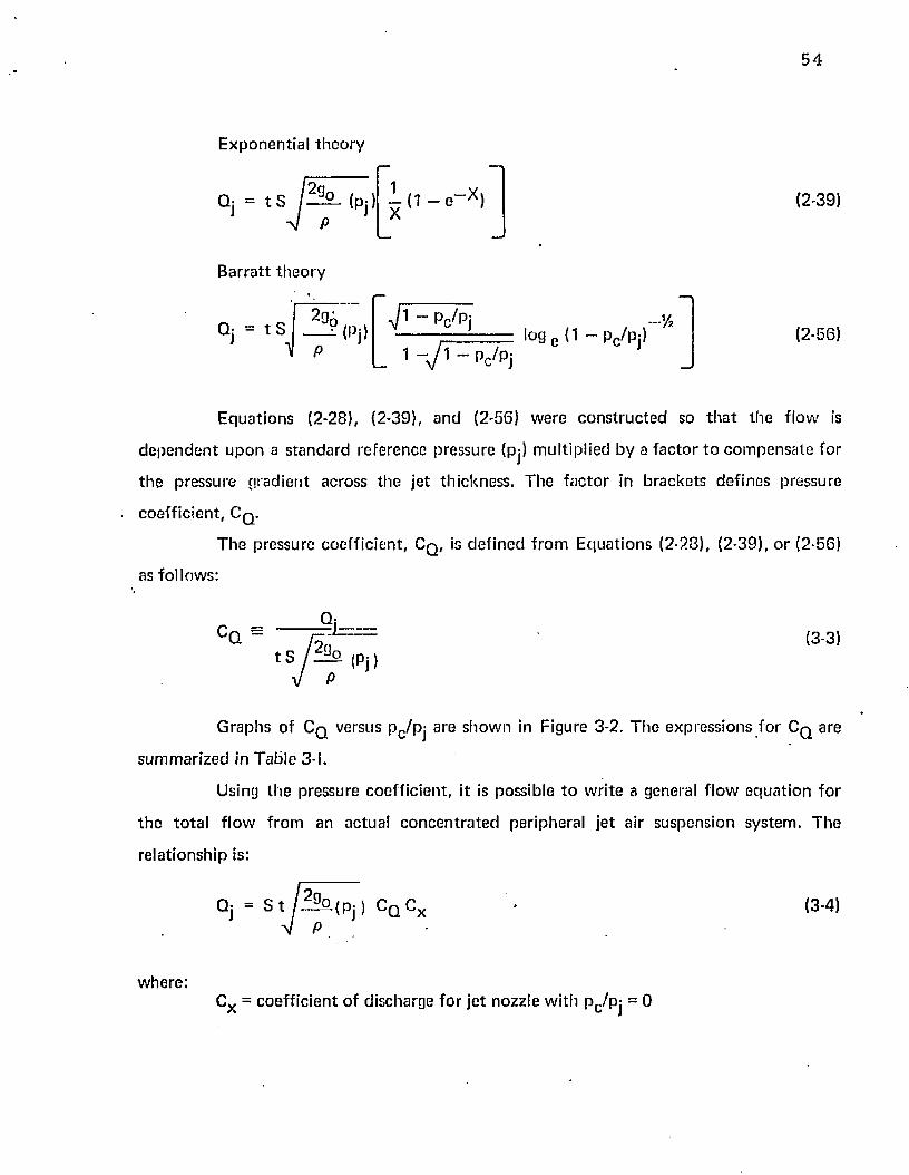
54
E xponen tia l th e o ry
Qj = t s p ° - (P j )
B arra tt th eo ry
1- ( 1 - e “ X ) X
Qj = t S —?<Pj) -y/l Pc/Pj
_ 1 - y i ~ p^ /p j! o g e (1 - pc/pj)
» %
(2-39)
(2-56)
E q u a tio n s (2-28), (2-39), an d (2-56) w ere c o n s tru c te d so t h a t th e f low is
d e p e n d e n t u p o n a s tandard reference pressure (pj) m ultip lied by a f ac to r to c o m p e n sa te fo r
t h e p ressure g rad ien t across the je t th ickness. The f a c to r in b racke ts defines pressure
coeff ic ien t , Cq.T h e pressure coeff ic ien t , Cq, is de fined f ro m E qua tions (2-23), (2-39), o r (2-56)
as fo llows:
CQ =Q
' 2 3o(3-3)
t S izzsl (Pj)
G raphs of Cq versus Pc /Pj are show n in Figure 3-2. T h e expressions fo r Cq are
sum m arized in Tab le 3-I.
Using th e pressure coeff ic ien t , it is possible to w rite a general f low eq u a tio n fo r
th e to ta l f low f rom an actual c o n c e n t ra te d peripheral jet a ir suspension sys tem . T he
re la tionsh ip is:
Qj = s t / ^ S a i P j ) c Q c x (3-4)
w here :Cx = coeff ic ien t of discharge fo r je t nozzle w ith p c/p j = 0
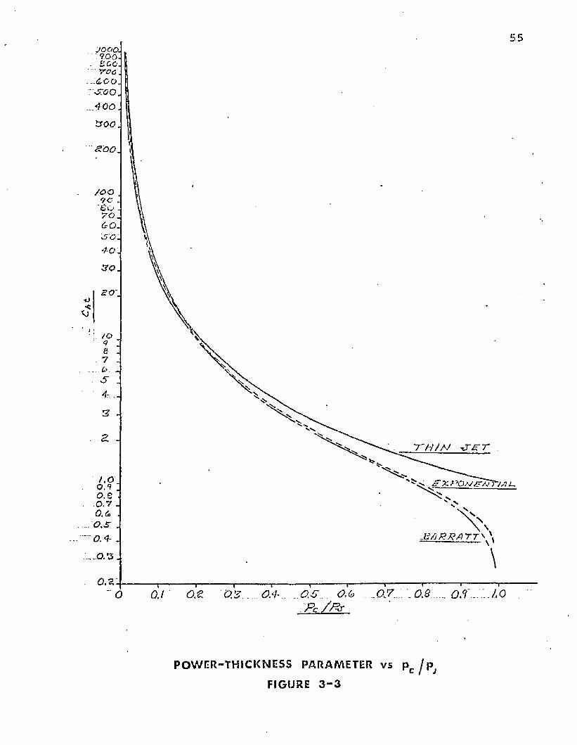
55JOOO.■ 9.0 0 -s c o .
■ yoa ...4 Go. S C O .. 4 0 0
t ro o
z o o , i
/ o o9C
' € O 7 0 .
6 0 .
■*5O. 4 0
3 0 .
-*JSO~
t o9e7& . s4.
3 -
2 *
/ . ' O ' 0.9 qo .e
. 0 .7 q 0 .6 0.3- .
0.4- . . . 0 . - 3 .
o .s :
T H / N ■OS’T
^ jt x t^o/vtr/JriA l.
E/iP .RflTT^ \ \ '
\0 O.t 07 0 7 . 0 7 0.5 0.6 0,7. .0.8 O/f . '.J.O
P c / P x
P O W E R - T H I C K N E S S PARAME TER v s p Q j pj
FIGURE 3 - 3
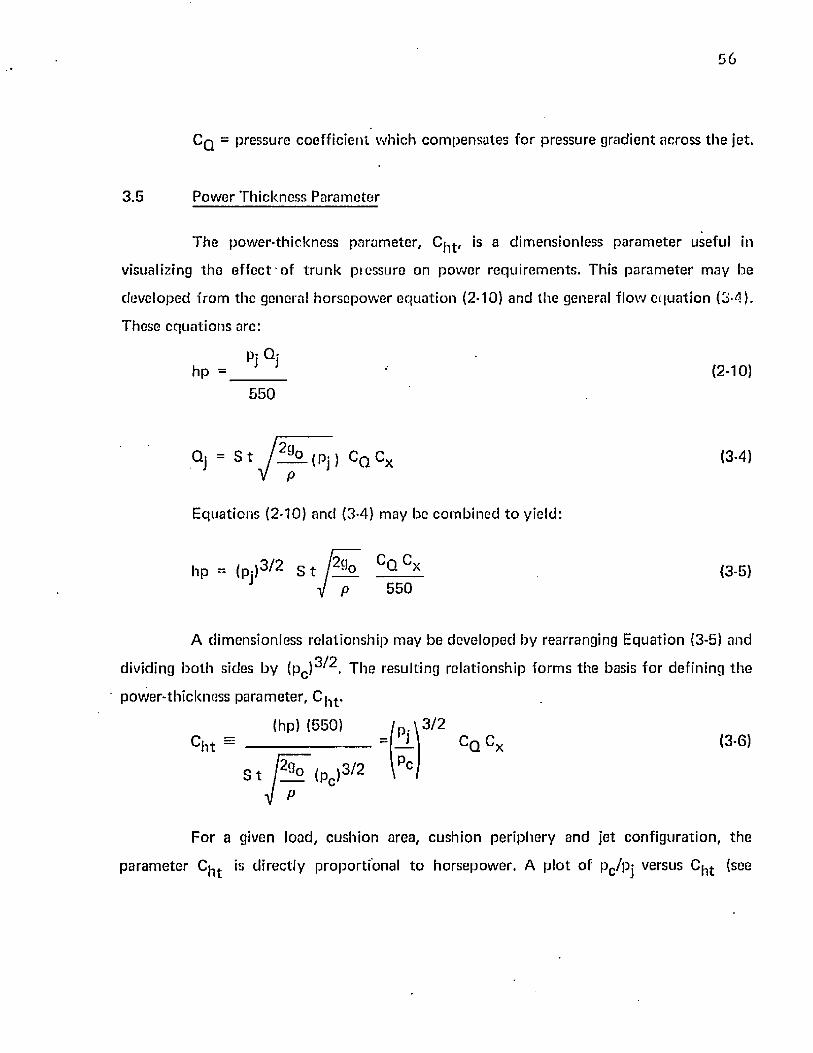
56
C q = pressure coeff ic ien t w hich c o m p e n sa te s fo r pressure grad ien t across th e jet.
3 .5 Pow er T h ickness Param ete r
T h e pow er-th ickness pa ram ete r , C|l t , is a d im ensionless pa ra m e te r useful in
visualizing th e e f fe c t of t r u n k pressure on p o w er requ irem en ts . This p a ra m e te r m ay be
deve loped from the general h o rsep o w er e q u a t io n (2-10) and the general f low e q u a tio n (3-4).
These e q u a t io n s are:
pj Qjhp = (2-10)
5 5 0
Qj = S t M l , Pj , Cq Cx (3-4)
E qua tions (2-10) and (3-4) m ay be co m b in ed t o yield:
hp = (pj)3 /2 S t r ! o CQ C* (3-5)J V p 550
A dim ensionless re la tionsh ip m ay be developed by rearranging E qua tion (3-5) and
dividing b o th sides by (pc )3j/2. T he resulting re la tionsh ip fo rm s th e basis fo r defin ing th e
pow er-th ickness p a ram ete r , C | l t .
Ch t ~( h p ) (550)
S t / ? ? 2 (pc )3 /2
\ 3 /2CQ Cx (3-6)
F or a given load, cush ion area, cush ion pe riphery and jet con figu ra t ion , th e
p a ra m e te r Cjl t is d irec tly p ropo rt iona l t o ho rsepow er . A p lo t o f pc /p j versus C^j. (see
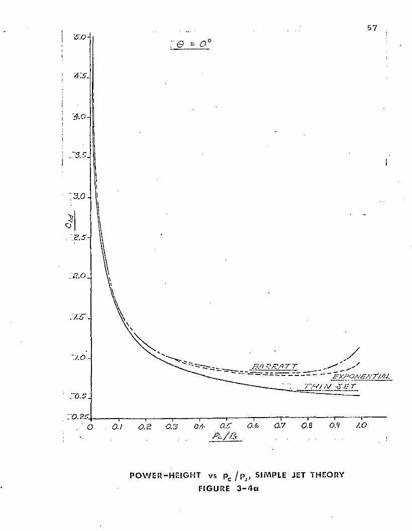
57
i
.4 .0
o -
/FXPOA'/ZA' T M L7" ,v / A/ -J ' l - r
0.7 o.e0.1P c / a
P O W E R - H E l G E ' T vs pc / pJf SIMPLE JET THEORY
FIGURE 3 - 4 a
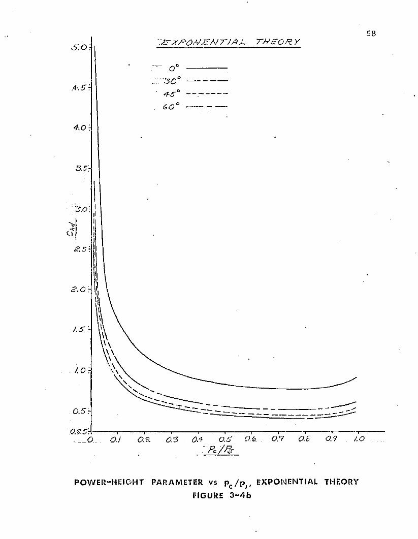
58T J A X T W ZO R . Y5 .0 \
S O
A O r
O.Sr
0 5 0 ,6 0 5 AOO.i: P c Z &
P O W E R-H EIGHT PARAMETER v s pr / p , EXPONENTIAL THEORYC J
FIGURE 3 - 4 b
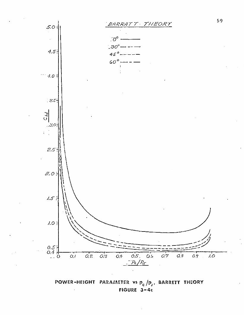
a / iR K /} r r t /p s o x y
i s
OS OS OS OS. OS 0.7 0.8 0.9 1.00.1oPc / P^r
P O W E R - H E I G H T PARAMETER v s p c / p j ( BARRETT THEORY
FIGURE 3 - 4 c
60
Figure 3-3) sh o w s h ow , o th e r p a ra m e te rs be ing c o n s ta n t , increases in t ru n k p ressure cause
increases in h o rsep o w er .
3 .6 Pow er-H eigh t P a ram e te r
T h e p o w er- th ickness p a ra m e te r , deve loped in S ec t io n 3 .5 , d o e s n o t inc lude th e je t
he igh t (d) in t h e re la t ionsh ip . In th e design o f a pe riphera l je t air cush ion sy s tem , it is
genera lly des irab le t o m ax im ize je t he igh t a n d m in im ize pow er . A d im ens ion less p a ra m e te r
w hich inc ludes b o th h o rse p o w er a n d je t he igh t m ay b e dev e lo p ed by m u lt ip ly ing b o th sides
o f E q u a tio n (3-6) b y th e ra t io ( t /d ) . T h e resu lt is de f ined as Cjicj th e pow er-he igh t p a ra m e te r .
Tidhp 5 5 0
d
1
<Pc>3 / 2
3 /2c Q c x (3-7)
E q u a t io n (3-7) c o n ta in s h o rse p o w e r and je t he igh t as a ra t io . S ince it is desirab le
t o m in im ize p o w e r a n d m ax im ize j e t he igh t, a m in im u m value o f th e p a ra m e te r sh o u ld
be se lec ted as a design po in t .
G raphs o f C j ^ versus pc /p j fo r 0 = 0 a n d Cx = 1.0 are sh o w n in Figure 3-4(a).
T h e e f fe c t o f 0 is s h o w n in F igure 3-4 (b a n d c). It is ev iden t f ro m Figure 3 -4 (a) t h a t design
p o in ts in th e range o f p c/p j = 0 .4 t o p c /p j = 0 .9 are desirab le f ro m a m a x im u m je t he ight,
m in im u m p o w e r s ta n d p o in t .
3 .7 A u g m e n ta t io n R a tio
T h e a u g m e n ta t io n ra t io is, in fac t , a lift c o e ff ic ie n t fo r th e vehicle. T h is p a ra m e te r
is d e f in e d a t least seven d i f fe re n t w a y s in th e l i t e r a t u r e , ^ d e p e n d in g on th e c h o ice o f th e
re fe rence fo rc e in E q u a t io n (3-1). O n ly one d e f in i t io n will be co n s id e red hero. T h e refe rence
fo rce a ssu m ed h ere is t h e m a x im u m th ru s t w hich c o u ld be g enera ted if th e je t nozz le
61
exhaust were discharged vertically dow nw ard . This th ru s t has been designated F j. The
expression for th e augm en ta t ion ratio is:
pressure su p p o r t H- actual jet th ru s t in vertical d irectionA, =
ideal jet th rus t
or
A | = P° A° + Fi C° S() (3.8)
Fi
An expression for Fj may be developed by evaluating the to ta l change of
m o m e n tu m in th e vertical direction for the air as it flows from the t ru n k to the a tm osphere .
If th e simple jet th e o ry is assum ed, the m agnitude of the to ta l m o m en tu m of the je t a t th e
exhaust plane is given by Equation (2-26).
J ' = 2 S t Pj (2-26)
T he m o m e n tu m of th e gas in th e t ru n k is assum ed to be zero. The m agnitude of th e jet
th ru s t m ay be w ritten :
Fj = 2 S t Pj (3-9)
E quation (3-9) m ay be subs ti tu ted in to E quation (3-8) and th e result rearranged
t o give an expression which relates A | to pc/pj. T he resulting equa tion is:
A | = c o s 0 + (pc/pj)
/
A, (3-10)2 St
E quation (3-10) may be fu r th e r simplified by assuming the cushion is circular in
shape. F o r a c ircu lar shaped cushion w ith a d iam eter , D ,
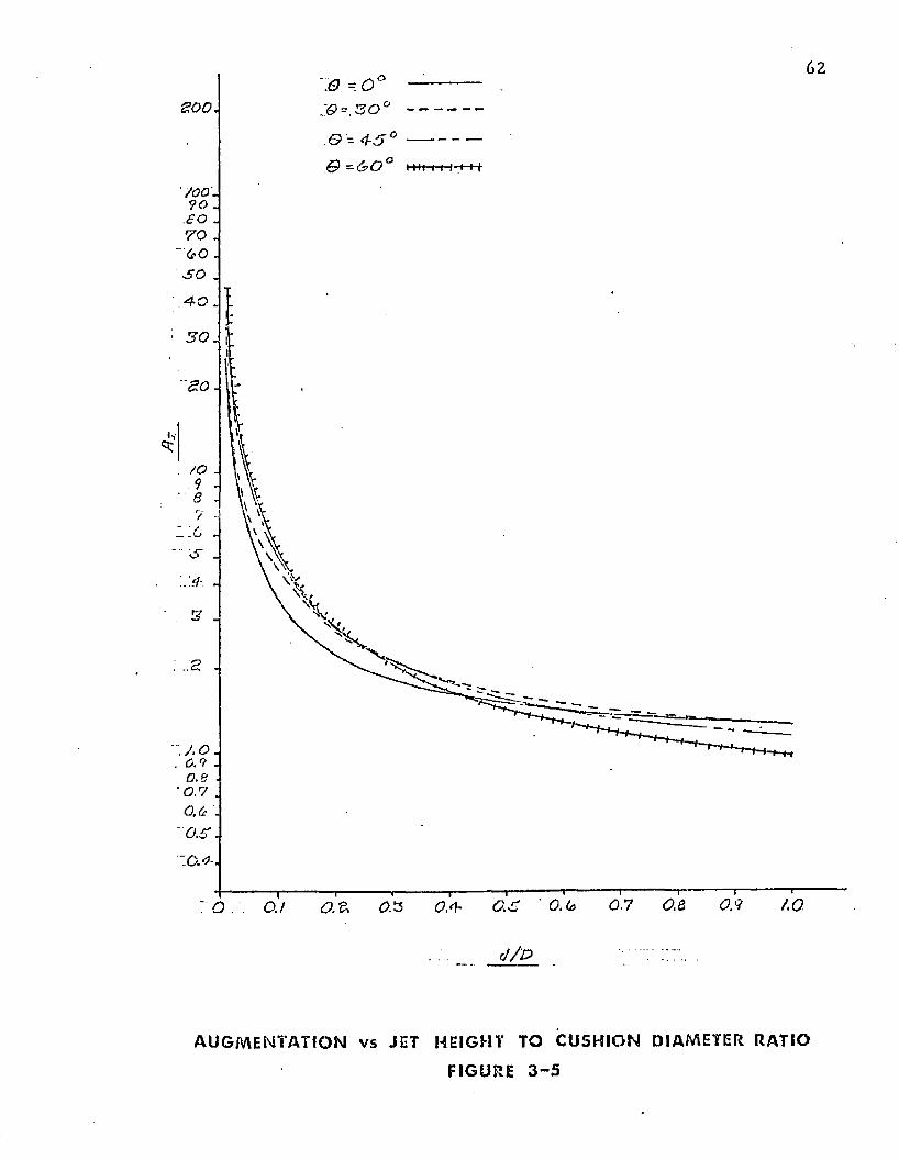
62
£00
6> = 4-5
' 700' . ?o .
.60 .
TO . ~'0O . v50 .
0.7 O.e 0 5 / .o£>.£ 0.3 Osh0.1
d / D
A U G M E N T A T I O N v s JET HEI GHT TO C U S H I O N DIAMETER. RATIO
FIGURE 3 - 5
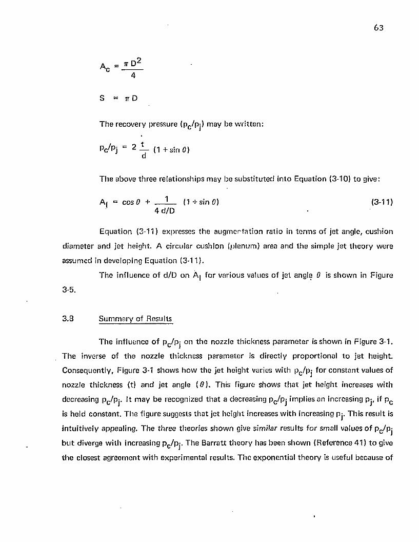
63
4
S = 7T D
T h e recovery p ressure (pc /pj) m ay be w r i t te n :
Pc/Pj ~ 2 JL_ {1 + s jn 0)a
T h e above th re e re la t ionsh ip s m ay be s u b s t i tu te d in to E q u a t io n (3-10) to give:
Aj = cos 0 + — ___ (1 + s i n 0 ) (3-11)4 d /D •
E q u a t io n (3-11) expresses th e a u g m e n ta t io n ra tio in t e rm s o f je t angle, cu sh io n
d ia m e te r a n d je t he igh t. A c ircu la r cu sh io n (p lenum ) area an d th e s im ple j e t th e o ry w ere
a ssum ed in deve lop ing E q u a t io n (3-11).
T h e in f lu en ce o f d /D on A | fo r va rious values o f je t angle 0 is s h o w n in F igure
3-5.
3 .8 S u m m a ry o f Results
T h e in f lu en ce o f p c /p j on th e nozz le th ic k n e ss p a ra m e te r is s h o w n in F igure 3-1.
T h e inverse o f th e nozz le th ic k n e ss p a ra m e te r is d i rec t ly p ro p o r t io n a l to je t he igh t .
C o n s e q u e n t ly , F igure 3-1 sh o w s h o w th e je t h e ig h t varies w i th pc/p j fo r c o n s ta n t values o f
nozz le th ic k n e ss (t) a n d je t angle ( 0 ) . T h is figure sh o w s t h a t j e t he ig h t increases w ith
decreasing Pc /pj- I t m ay be recogn ized t h a t a decreasing p c /p j im plies an increasing Pj, if p c
is he ld c o n s ta n t . T h e figure suggests t h a t j e t h e igh t increases w i th increasing pj. T h is re su l t is
in tu i t iv e ly appealing . T h e th re e th eo r ie s s h o w n give s im ila r resu lts f o r small values o f pc /p j
b u t diverge w ith increasing p c/p j . T h e B arra t t t h e o r y has been sh o w n (R e fe re n ce 41 ) t o give
t h e c losest a g re e m e n t w i th e x p e r im e n ta l results . T h e e x p o n e n t ia l t h e o r y is usefu l be c au se o f
i
64
its relative s im plic ity and its close agreem ent with th e m ore com plicated Barratt theo ry . The
sim ple je t th e o ry is accu ra te on ly a t low values of pc /pj and X (say Pc/pj < 0 . 4 and X <
0.2). It is useful in developing sim ple preliminary relationships and trends.
T h e influence o f pc /pj on th e pressure coeffic ien t (Cq) is show n in Figure 3-2. F or th e theories p resen ted , th is rela tionship is independen t of the je t angle, 0 . T he figure
show s th a t a high value of pc /p j is desirable to minimize th is coefficient.
T he influence of p c /pj on th e power-th ickness pa ram ete r is show n in Figure 3-3.
T he param eter, C|l t , is d irec tly p roportiona l to in p u t power. Figure 3-3 shows th a t , fo r
c o n s ta n t values of nozzle area and cushion pressure (aircraft weight), high values of pc /pj
(low values of pj) are desired fo r m in im um power.
T he influence of pc /pj on th e pow er-height pa ram ete r (C ^ j) is show n in Figure
3-4. It is generally desirable to m inimize pow er and m axim ize jet height. For cons tan t pc
(aircraft w eight), and fuselage perim eter (S), a m in im um C|1cj w ould give a m ax im um jet
he igh t and m in im um pow er inpu t. Figure 3 -4 (a) show s th a t b o th th e exponen tia l and the
. B arra tt th e o ry give curves w ith m in im um values a round P C/Pj = 0 .7 . Since the curve is
fla t in Die region of ~ 0 .4 t o P c/Pj = 0 .9 a considerable la t itude exists in selecting an
o p t im u m Pc/Pj.
T he influence o f 0 on th e power-je t height pa ram ete r is show n in Figure 3-4(b
and c). T he curves show th a t a high value o f 0 is desirable. However, if 0 becom es to o
large, th e f low will a t tach to th e unders ide o f th e a ircraft and the m o m e n tu m seal will be
lost. A value of 0 ~- 6 0 ° is generally considered as th e m ax im um practical.
T he e ffec t of th e je t height to cushion d iam e te r ratio on augm en ta t ion ratio fo r a
circular cush ion is show n in Figure 3-5. The figure shows th a t it is desirable t o have small
values o f d /D for m ax im um augm en ta t ion . Large values of augm en ta tion are desirable to
m inim ize power. T he value o f jet height (d) is generally de te rm ined by the roughness o f the
terra in on which th e vehicle is designed to opera te . C onsequen tly , d is largely independen t
o f vehicle size. For m ax im um augm en ta t ion it is desirable to m ake th e cushion d iam eter as
65
large as possible w i th o u t v io lating s truc tu ra l w eigh t and d y n am ic constra in ts .
In s u m m a ry , Figure 3-3 show s t h a t p o w er decreases w ith increasing Pc/Pj if je t
he igh t is a llow ed t o decrease. However, fo r a specified value of je t he igh t it is desirable to
select a value o f pc /p j in t h e range o f 0 .4 to 0 .7 . Figures 3 -4(b and c) sh o w th a t it is
desirable t o em p lo y a je t angle 0 o f a t least 3 0 ° . Larger angles, up to 6 0 ° , give slight
add it iona l benefits in m inim izing th e pow er-heigh t pa ram ete r . Finally , Figure 3-5 show s th a t
it is desirable to m ake th e vehicle d iam e te r large and th e je t c learance small fo r m ax im u m
au g m e n ta t io n .
TABLE 3-1
. tE x p r e s s i o n s fo r Pj or M o m e n tu m P lo w T h e o r ie s
X ^ P A R A M E TER
THEORYP*/Pj
n'“Q
SIM PL E J E T 2X 1. 0
E X P O N E N T IA L-2X
1 - e X J
B A R R A T T 2 X { V X 2 , 1 - X) V 1 - P c ^ i -% l o q e (1 pc/p:)
1 — i/I — Pc/Pj
oo
4. PREDICTION OF THE SHAPE OF A TWO DIMENSIONAL AIR CUSHION TRUNK
4.1 A pproach
A ccura te p red ic tions of th e cross-sectional shape and area of t h e air cu sh ion t ru n k
are necessary in de te rm in ing th e f low rate, jet height, s tiffness and d y n am ic response o f th e
system . It is desired to p red ic t th e t ru n k shape w hen it is sub jec ted to tw o types o f loading.
T he first ty p e occurs w hen th e a irc ra f t is being su p p o rte d to ta l ly b y th e air
cush ion . In th is case, the t ru n k tran sm its none of th e load d irec tly to th e g round . T he t ru n k
shape associated w ith th is ty p e of loading is i l lus tra ted by Figure 4-1. This case is called th e
Free T ru n k Shape. It is developed in detail in Sec tion 4 .4 .
T he second ty p e o f loading occurs during d y n am ic loading o f the a ir cush ion . In
th is case, a p o r t io n of t h e t ru n k m ay be f la t ten ed against th e g round and t ra n sm its loads to
th e g round th ro u g h a th in layer of air. T he t ru n k shape associated w ith this ty p e of loading
is i llustra ted in Figure 4-2. This case is called th e Loaded T ru n k Shape. It is deve loped in
Sec tion 4 .5 . C o m p u te r p rogram s w hich p red ic t these tw o shapes fo r an inelastic t ru n k
material are p resen ted in A ppend ices I and II respectively. A ppend ix III con ta ins a
c o m p u te r p rogram fo r p red ic ting th e Free T ru n k Shape including th e e ffec ts of t ru n k
material w hich have non-linear e lasticity .
4 .2 Background
T he con figu ra t ion and loading of th e t ru n k o f th e A ir Cushion Landing System is
considerab ly d if fe ren t f ro m th e t ru n k on A ir Cushion Vehicles. C onsequen tly , th e li tera tu re
associa ted w ith a ir cush ion vehicle t ru n k s is o f little assistance in p red ic ting th e ACLS shape.
Esger and M o r g a n ^ ) c o n d u c te d an analysis o f th e energy absorp tive
charac te r is t ics o f gas bags o f various shapes and a t various rates o f gas b leed. T h e s tu d y
67
y
,VT x « ;
( ^ o ^ y o )
FREE T R U N K S H A P E
FI GURE 4 - 1oCO
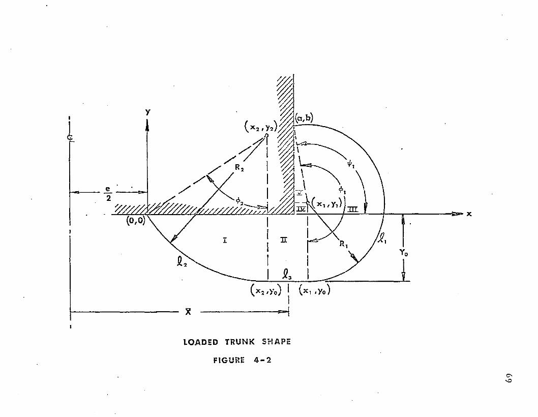
L O AD E D T R U N K S H A P E
FIGURE 4 - 2
70
included cylindrical shaped bags im pacted on the ir sides. This case approaches the Loaded
T ru n k Shape problem . These au th o rs found th a t th e deflected cross-sectional shape
app ro x im ated tw o circular arcs ta n g e n t to th e g round surface and connec ted by a stra ight
line a t the g round con tac t. A similar cond it ion is show n in Figure 4-2.
In th e sections to follow, numerical so lu tions to p red ic t th e shape o f the t ru n k
u n d e r b o th free and loaded cond it ions are p resented . Digital c o m p u te r program s w hich
evaluate th e t ru n k shape to r these cond it ions are presented in A ppendix I and A ppend ix II.
Tiie rela tionships which are co m m o n to b o th the free and th e loaded t ru n k shape
are presented in Section 4.3.
4 .3 D evelopm ent o f C om m on Relationships
4.3.1 A pproach
In th is section, th e variables associated w ith the t ru n k shape are listed, th e laws
w hich will be applied are s ta ted , and the relationships which are co m m o n to bo th problem s
are developed.
T he variables fo r th is p rob lem are illustrated in Figures 4-1 and 4-2. T h e y m ay be
grouped as follows:
Independen t Design Variables
a(a) x c oo rd ina te of (horizontal distance betw een) t ru n k a t ta c h m e n t points,
ft.
b(b) y coo rd ina te o f (vertical d istance betw een) t ru n k a t ta c h m e n t points , ft.
e d istance be tw een lower t ru n k a t ta c h m e n t points, f t (see Figure 4-8).
71
£ cross-sectional length of t ru n k m ateria l, f t.
£ 0 cross-sectional length o f th e t ru n k m aterial a t th e design p o in t , f t (see
Figure 4-14).
Et t h e u n i t e longa tion per p o u n d of ten s io n per foo t- leng th in th e axial
d irec tio n fo r th e t ru n k m ateria l, l b / f t (see Figure 4-14).
In d ep e n d e n t O pera ting Variables fo r F ree T ru n k S hape
pc (Pc ) = cush ion pressure, psfg (psf).
Pj(Pj) = t r u n k pressure, psfg (psf).
Fo r th e Loaded T ru n k Shape, one add it ional in d e p e n d e n t variable is:
Y Q = vertical d istance b e tw een th e a ircraf t hard s tru c tu re and b o t to m of
th e t ru n k (ft).
D ep en d en t Variables
£■) length o f t ru n k segm en t inscribed by angle -j, f t.
S-2 length o f t ru n k segm en t inscribed by angle <f>2 , f t.
£ 3 length of t ru n k segm en t f la t te n e d against th e g round , ft.
R'j rad ius o f cu rv a tu re fo r segm en t £ - j , f t .
R 2 rad ius o f c u rva tu re fo r segm en t £ 3 , ft.
72
ten s io n in t r u n k m ateria l, p o u n d s in tangen tia l d i re c t io n per fo o t- le n g th
in th e axial d i re c t io n , lb /f t .
d is ta n c e f ro m a irc ra f t c e n te r o f gravity to c e n te r o f pressure o f t h e
t r u n k f o o tp r in t , f t .
x c o o rd in a te of i* * 1 p o in t , ft.
y c o o rd in a te o f i* * 1 p o in t , ft.
cen tra l ang le fo rm e d by t ru n k segm en t C-], radians,
cen tra l angle fo rm e d by t r u n k segm en t C 2 , radians.
T h e law s to be app lied t o th is p ro b le m are :
(1) Force eq u il ib r iu m app lied to t h e t ru n k
(2) L oad -e ionga tion o f th e t ru n k
(3) G e o m e tr ic c o m p a t ib i l i ty o f th e t r u n k shape
T h e f irs t tw o laws ho ld fo r b o th t r u n k shapes . T h e d if fe re n c e in th e tw o p rob lem s
lies in th e g e o m e tr ic c o m p a t ib i l i ty a ssum ptions . C o n se q u e n tly , t h e f irs t tw o re la t ionsh ip s
will be d e v e lo p e d in S ec t io n s 4 .3 .2 and 4 .3 .3 t o fo llow .
4 .3 .2 F o rce E qu il ib r ium
C o n s id e r a n e lastic m ateria l o f leng th a t ta c h e d t o th e s t ru c tu re a t p o in ts (a,b)
an d (0 , 0 ) as sh o w n in F igures 4-1 o r 4-2. T h e t r u n k is sub jec ted t o an in ternal p ressure Pj, to
Vi
<p2
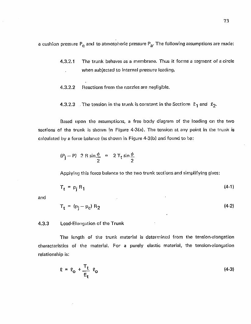
73
a c u sh io n pressure Pc a n d to a tm o sp h e r ic p ressure Pa . T h e fo llow ing a ssu m p tio n s are m ade :
4 .3 .2 .1 T h e t r u n k behaves as a m e m b ran e . Thus it fo rm s a s e g m e n t o f a circle
w h e n su b je c ted t o in te rnal p ressu re loading.
4 .3 .2 .2 R eac tio n s f ro m th e nozz les are negligible.
4 .3 .2 .3 T h e ten s io n in th e t ru n k is c o n s ta n t in th e S ec t io n s £-j an d £2 .
Based u p o n th e assu m p tio n s , a free b o d y d iagram o f th e loading on th e tw o
sec t io n s o f th e t r u n k is sh o w n in Figure 4 -3 (a ) . T h e ten s ion a t any p o in t in th e t r u n k is
ca lcu la ted by a fo rce ba lance (as sh o w n in Figure 4 -3 (b ) and fo u n d t o be:
(Pr — P) 2 R s i n i _ = 2 T t s i n A J 2 2
A pply ing th is fo rce b a lance to th e tw o t r u n k sec t ions an d sim plify ing gives:
T t = Pj R 1 <4-1)
a n d
T t = (pj - p c ) R 2 (4-2)
4 .3 .3 L oad -E longa tion o f t h e T ru n k
T h e length o f t h e t r u n k m ateria l is d e te rm in e d f ro m th e ten s io n -e lo n g a tio n
c h a rac te r is t ic s of th e m ate ria l. F o r a pu re ly e las t ic m ate ria l, t h e ten s io n -e lo n g a t io n
re la t io n sh ip is:
£ = C0 + fi0 (4-3)
^ t
(a ) D I A G R A M o r P R E S S U R E - T E N S I O N E Q U I L I B R I U M
( b ) D I A G R A M O F T E N S I O N C O M P O N E N T
FREE B O D Y D I A G R A M O F T R U N K L O A D I N G
FI GURE 4 - 3
75
In general, t h e e las t ic ity of t ru n k m ateria ls wilt b e non-linear. C o n se q u e n tly , a
m o re c o m p lic a ted re la t ionsh ip th a n E q u a t io n (4-3) m u s t be used, A typica l
ten s io n -e lo n g a tio n curve fo r a t r u n k m ateria l is sh o w n in F igure 4-14.
4 .3 .4 G e o m e tr ic C o m p a tib i l i ty1
T h e g e o m e tr ic c o m p a t ib i l i ty c o n d i t io n s o f th e f ree t ru n k shape p ro b le m d iffe r
f ro m th e loaded t r u n k shape p ro b lem . T h e d iffe rences are sh o w n in F igures 4-1 and 4-2,
respectively . S e p a ra te d e v e lo p m e n t o f th e geom etr ic c o m p a t ib i l i ty c o n d i t io n s will be
p resen ted in Sec tions 4 .4 and 4 .5 .
4 .4 Free T r u n k Shape
4.4 .1 A ssu m p tio n s
A cross sec t io n of t h e f ree t r u n k shape is sh o w n in Figure 4-1. In a d d it io n to th e
a s su m p tio n s listed in S ec tion 4 .3 .2 th e fo llow ing res tr ic t io n s a re im posed :
4 .4 .1 .1 T h e pressure change f ro m Pc t o Pa o ccu rs over a s h o r t d is tance in th e
v icin ity of p o in t (xQt y Q).
4 .4 .1 .2 T h e t r u n k is assum ed t o be ta n g e n t to t h e g round a t p o in t (x0 , y 0 ). No
f la t te n in g of t h e t ru n k a ro u n d p o in t (xQ, y 0 ) is a llow ed . Th is
a s su m p tio n requ ires t h a t t h e c e n te rs o f cu rv a tu re fo r radii an d R 2
have th e sam e x c o o rd in a te .
4 .4 .2 G e o m e tr ic C o m p a tib i l i ty (F ree T r u n k Shape)
T h e assum ed t ru n k g e o m e try is sh o w n in F igure 4-1.
76
In o rd e r fo r t h e t r u n k segm en ts fo rm e d by fi-j an d C2 t 0 b o t l 1 be ta n g e n t t o th e
g ro u n d a t (xQ, y Q) th e c e n te rs o f cu rv a tu re m u st hove th e sam e x c o o rd in a te . T h u s
x-j = x Q (4-4)
x 2 = x 0 . (4-5)«
T h e d is ta n c e b e tw e e n (o, o) a n d (x2 , y 2 ) is R 2
(x 2 - o ) 2 + {y2 - o ) 2 = R 2 2 (4-6)
T h e d is ta n c e b e tw e e n (x-| y-j) and (a,b) is
( x 1 — a ) 2 + ( y 1 - b ) 2 = R - | 2 (4-7)
T h e d is ta n c e b e tw e e n (x 0 , y Q) a n d (x 2 ,y 2 ) is R 2 . S ince x Q = x 2 t h e d is tan ce is
s im p ly th e y d is tance :
y 2 " V o = R 2
S im ila r ly , t h e d is ta n c e b e tw e e n (xQ, y 0 ) an d (x-j, y-j) is R-j.
Vi - Y0 = R 1 (4 ' 9 )
T h e a rc fo rm e d b y £ 2 is d e f in ed b y 0 2 . T h e angle 0 2 m ay b e w r i t t e n in
t r ig o m e tr ic t e r m s as:
X — Q
0 2 = a rc t a n —? ---------■ o < 0 n < t t rad ians (4-70)*■ V 2 ~ °
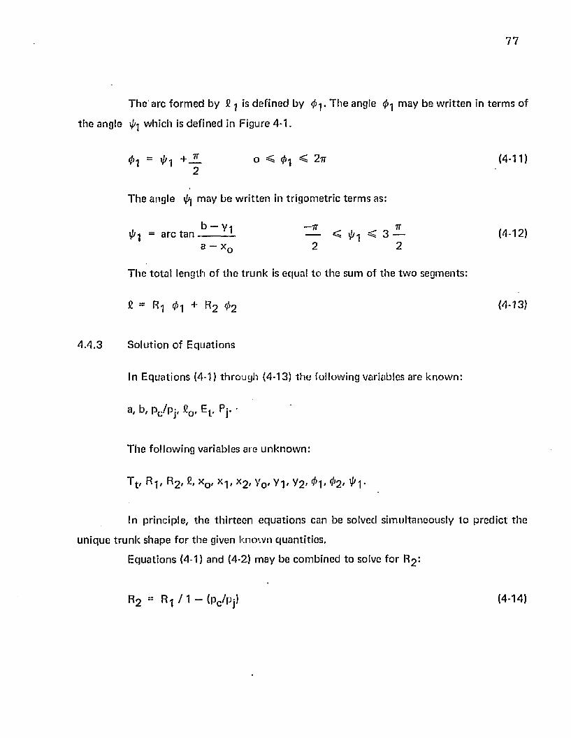
77
T h e arc fo rm e d by £ is d e f in e d by T h e angle <f>i m ay be w r i t t e n in te rm s of
t h e angle ^ whicii is d e f in e d in F igure 4-1.
0 ! = + — o ^ ^ < 2 tt (4-11)2
T h e ang le i/*| m ay be w r i t te n in t r ig o m e tr ic t e rm s as:
b — V i — I T I T= a rc t a n L — < < 3 — (4-12)
a - x c 2 2
T h e to ta l length o f t h e t r u n k is equal to th e sum o f th e tw o segm en ts :
= R l 0 i + R 2 ^ 2 <4 *13}
4 .4 .3 S o lu t io n o f E q u a t io n s
In E q u a t io n s (4-1) th ro u g h (4-13) t h e fo llow ing variables are k n o w n :
a, b, pc /p j , £or Et , Pj. •
T h e fo llow ing variab les are u n k n o w n :
T t , R-j, R 2 * x 0 - x l* X2 , y 0 , y- |, V2 > $2> ^1*
In p rinc ip le , t h e th i r te e n e q u a t io n s can be so lved s im u lta n e o u s ly t o p re d ic t th e
u n iq u e t r u n k shape fo r t h e given k n o w n q u a n ti t ie s .
E q u a t io n s (4-1) and (4-2) m ay be c o m b in e d to solve fo r R2 :
R 2 = R-j / I — (pc /pj) (4-14)
78
E q u a t io n s (4-4) th ro u g h (4-9) m ay be com bined t o solve fo r y 0 . Com bin ing
E qua tions (4-4), (4-6) and (4-8) gives:
* o 2 + {Vo + r 2 > 2 = r 2 2
or
or
or
Let
*o2 - - y 02 - 2v0 R2 W-1S)
C om bin ing E qua tions (4-5), (4-7), and (4-9) gives:
lx 0 - a ) 2 + (y Q + R , - b ) 2 = R ^
x Q 2 = 2 a x 0 - a 2 - y Q 2 - b 2 + 2 R 1b + 2 y Qb - 2 R - |y 0 . (4-16)
E quating (4-15) an d (4-16) t o e lim ina te x 2 yields:
-Yo2 ~ 2 YoR 2 = 2 a x 0 - a 2 - y 0 2 - b 2 -f-2R1b + 2 y 0 b - 2 R 1 y 0
j 2X Q = -15. ( R 1 _ b - R2 ) + — + — - R , — (4-17)
a 2 2 a a
R i — b — Ro= 1 2 (4-18)
C 2 + J ^ _ - R i J L (4-19)2 2a
79
T h e n E q u a t io n (4-17) b e c o m e s :
xo = C 1 y o + c 2
C o m b in in g E q u a t io n s {4-20} an d (4-15) yields:
- Y o 2 - 2v 'o R 2 " (C 1 Vo + C2 )2
or
( C ! 2 + 1 )y 0 2 + 2 ( R 2 + C ^ g J y o + C 2 2 = 0
A p p ly in g th e q u a d ra t ic fo rm u la t o E q u a t io n (4-21)
= - 2 ( R 2 ‘, c 1c 2 } * a / ( 2 R 2 + 2 C 1 C2 ) 2 - 4 ( C 1 2 + 1 ) C 2 2' o ” ----------------------------------------------- ----------------------------------------------
2{C 1 2 + 1 )
T h e c h o ic e o f pos it ive or negative squa re ro o t is d e p e n d e n t on th e q u a n ti t ie s a, b,
a n d 2. A physica l r e p re s e n ta t io n o f th e tw o s o lu t io n s is sh o w n in Figure 4-4 . T h e f igure
i l lu s tra tes t h a t fo r given values o f a an d b th e negative squa re r o o t requ ires a larger va lue o f
£ t h a n th e positive sq u a re ro o t .
In o rd e r t o deve lop c r i te r ia f o r se lec ting th e sign o f th e sq u a re ro o t , c o n s id e r th e
case w h e re pc = o. F o r th is case, th e t r u n k tak e s th e sh ap e o f t h e a rc o f a circle o f rad ius R-j.
In o rd e r f o r th e c irc le to pass th ro u g h (o,o) and (a,b) th e rad ius m u s t equal a t least ha lf
t h e d is ta n c e b e tw e e n th e tw o po in ts . T h e m in im u m value fo r R-j w o u ld be Vz V a 2 + b 2 . T h e
value o f 2 a ssoc ia ted w i th th e m in im u m va lue o f R-j is t t / 2 V a 2 + b . Sm aller values o f 2
w o u ld requ ire larger values o f R j b u t sm alle r values o f YQ. C o n se q u e n tly , t h e positive
s q u a re ro o t gives th e desired s o lu t io n fo r th is case. Larger values o f 2 w o u ld requ ire larger
values o f R-j an d larger values o f Y 0 . C o n s e q u e n t ly , th e negative sq u a re ro o t w o u ld give th e
d es ired s o lu t io n fo r th is case.
(4-20)
(4-21)
(4-22)
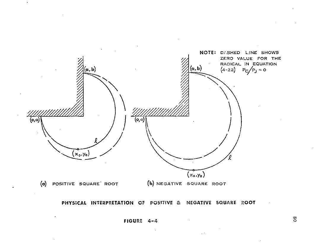
NOTE:
ID A SH ED LINE S H O W S ZERO VALUE FOR THE RADICAL IN EQUATION ( 4 - 2 2 ) P c / P j = 0
(a ) POSITIVE S Q U A R E ’ R O O T
( - o ^ o )
(fa) N E G A T IV E S Q U A R E R O O T
P H YS I C AL INTERPRETATI ON O r POSITIVE 3: NEGATIVE S Q U A R E R O O T
FI GURE 4 - 400o
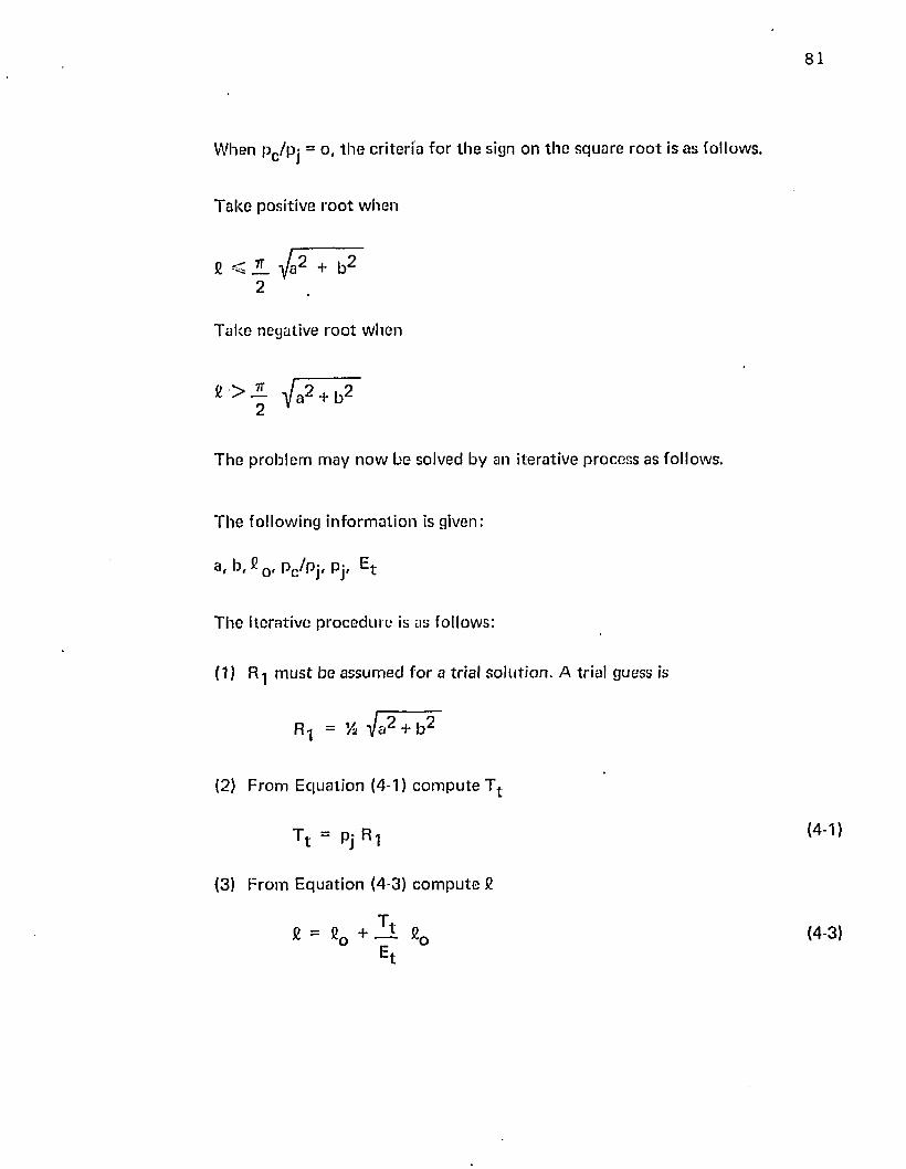
81
W hen pc /p j = o ( t h e c r i te r ia fo r t h e sign on th e sq u a re r o o t is as fo llows.
T a k e positive r o o t w hen
7T
2
T a k e negative r o o t w hen
« > - V a 2 + b 2 2 *
T h e p ro b le m m ay n o w be solved by an i te ra tive p rocess as fo llows.
T h e fo llow ing in fo rm a t io n is given:
a, b, £ 0 , p c /p j , pj, Et
T h e ite rative p ro c e d u re is as fo llows:
(1) m u s t be a ssum ed fo r a trial s o lu t io n . A trial guess is
(2) F rom E q u a t io n (4-1) c o m p u te T t
T t = P j R l(4-1)
(3) F ro m E q u a t io n (4-3) c o m p u te £
t(4-3)
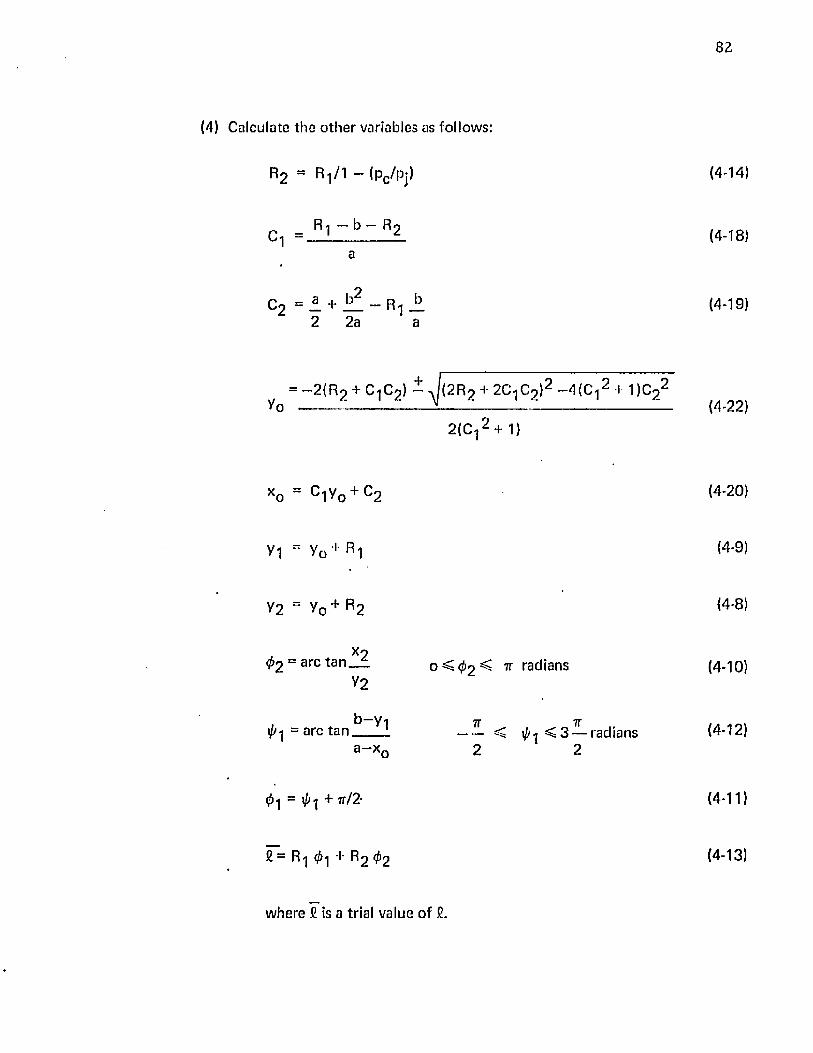
(4) Calculate th e o th e r variables as follows:
82
R2 = R-,/1 - (Pc/Pj) (4-14)
_ R 1 - b - R 2
° 1 " ---------------------- ( 4 - 1 8 )
2 ~ —— R 1 —2 2 a a
( 4 - 1 9 )
= —2{R 2 + C 1 C 2 ) - J ( 2 R 2 + 2C-|C 2 ) 2 —4 (C - | 2 I 1)C 2 2
Y o ------------------------------ ------------------------------------------------------
2 { C - j + 1 )
( 4 - 2 2 )
xo = C 1 V0 + C 2
y i = y 0 R t
y 2 = y 0 + R 2
( 4 - 2 0 )
( 4 - 9 )
( 4 - 8 )
Xo0 2 = arc t a n _ ±
t//-| = arc tan
Y2
b —y-|
a —x„
o < 0 2 ^ ^ radians
7T ^ ^ „ 7T < 0 .. < 3 — radians
2 2
( 4 - 1 0 )
( 4 - 1 2 )
0 1 = ^ 1 + tt/2-
£ — R 1 0 -j R2 0 2
( 4 - 1 1 )
(4-13)
w here £ is a trial value o f £.
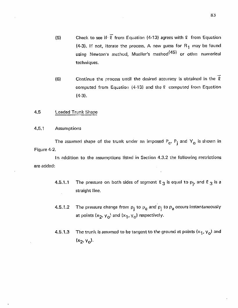
83
(5) C heck t o see if - £ f ro m E q u a t io n (4-13) agrees w i th £ f ro m E q u a t io n
(4-3). If n o t , i te ra te th e process. A new guess fo r R.] m ay be fo u n d
using N e w to n ’s m e th o d , M ueller 's m e t h o d ^ ^ o r o thei num erica l
te c h n iq u e s .
(6 ) C o n t in u e th e p rocess un til t h e des ired accu racy is o b ta in e d in th e £
c o m p u te d f ro m E q u a t io n (4-13) an d th e £ c o m p u te d f ro m E q u a t io n
(4-3).
4 .5 L oaded T r u n k S hape
4.5.1 A ssu m p tio n s
T h e a ssum ed shape o f t h e t r u n k u n d e r an im p o sed Pc , Pj and Y 0 is show n in
Figure 4-2.
In a d d i t io n t o t h e a s su m p t io n s listed in S ec tion 4 .3 .2 th e fo llow ing res tr ic t io n s
a re a d d e d :
4 .5 .1 .1 T h e p ressure on b o th sides o f segm en t £ 3 is equal t o pj, an d £ 3 is a
s t ra ig h t line.
4 .5 .1 .2 T h e p ressu re change f ro m Pj t o p c a n d pj to p g o ccu rs in s ta n ta n e o u s ly
a t p o in ts (x 2 , y 0 / an d (x-j, y 0 ) respectively.
4 .5 .1 .3 T h e t r u n k is a ssum ed to be ta n g e n t t o th e g ro u n d a t p o in ts (x-j, y Q) and
(x2 , Yo}*
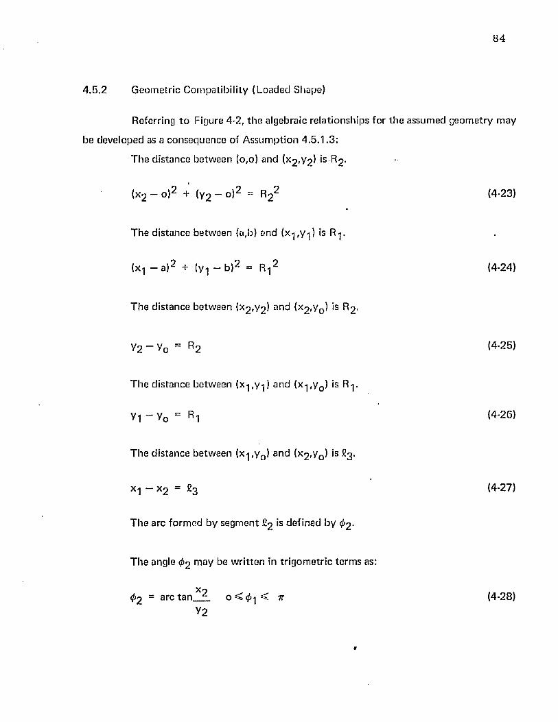
84
4.5.2 Geometric Compatibility (Loaded Shape)
Referring t o Figure 4-2, th e algebraic re la tionsh ips fo r th e assum ed geom etry m ay
be deve loped as a c o nsequence of A ssum ption 4 .5 .1 .3 :
T he d is tance be tw een (o,o) and (x 2 ,y?) is R2 -
(x 2 - o ) 2 + (y 2 - o ) 2 = R 2 2 (4-23)
T h e d is tance be tw een (a,b) and (x-|,y-j) is R-j.
(x-j — a ) 2 + (y-j — b ) 2 = R-j2 (4-24)
T he d is tance be tw een (x 2 ,Y2 ) ar>d (x 2 ,y 0 ) is R2 -
y 2 - V 0 “ R2 (4-25)
T h e d istance be tw een (x-j,y-j) an d (x-j ,y0 ) is R-j.
V1 “ V0 = R 1 <4 ' 2 6 )
T he d is tance be tw een (x-j,y0 ) and (x 2 ,y0 ) is 8 3 .
X1 “ x 2 = ^ 3 (4-27)
T h e arc fo rm e d by segm en t £2 's de fined by 0 2 -
T he angle 0 2 m ay be w r i t ten in t r igom etr ic te rm s as:
4>2 ~ a rc t a n X 2 o < 0 -j < tt (4-28)y2
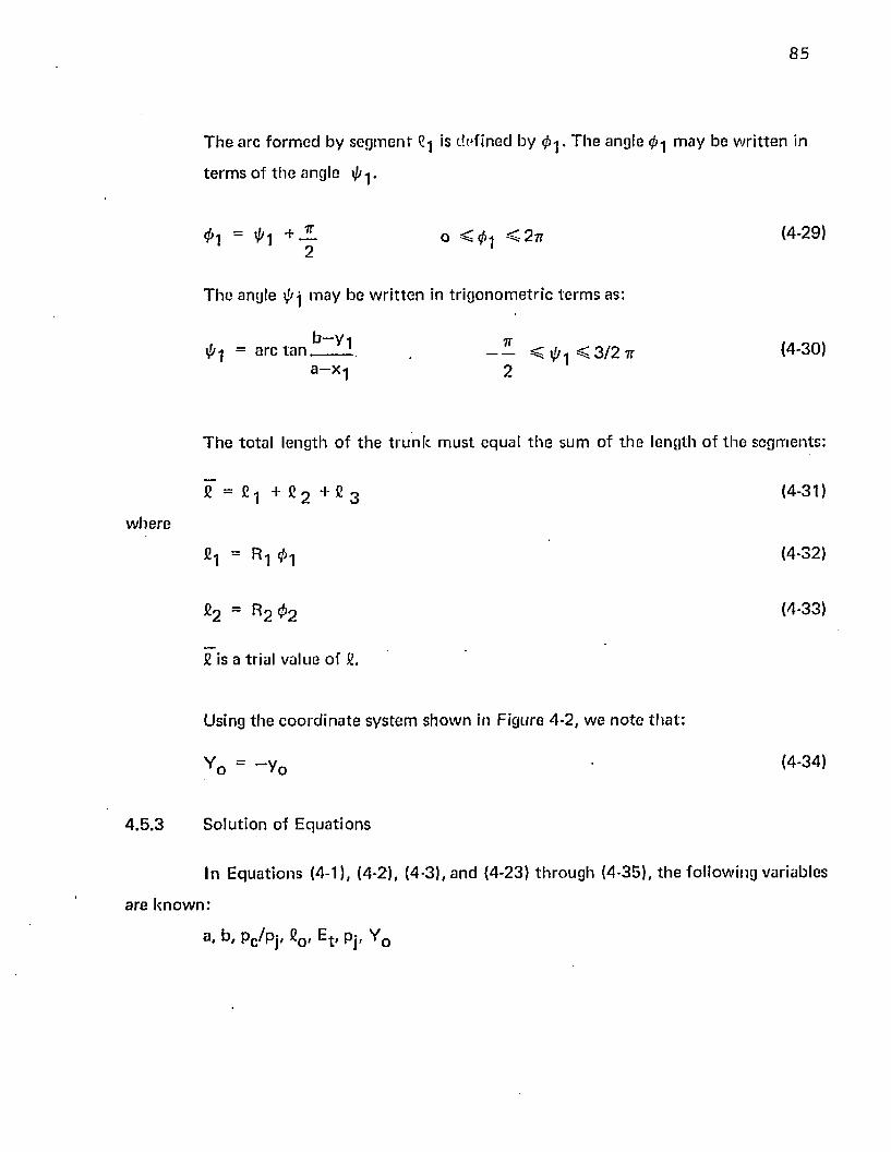
85
T h e a rc fo rm e d by s e g m e n t C-j is de fined by 0 - j . T h e angle 0-| m ay be w r i t t e n in
t e rm s o f t h e angle 0 ^.
0 1 = 0 1 + J L o < 0 i < 2 t t (4-29)2
T h e angle 0 j m ay be w r i t t e n in t r ig o n o m e tr ic te rm s as:
0 1 = a rc t a n —— s ^ 0 i < 3 / 2 7 t (4-30)a-x -l 2
T h e to ta l leng th o f t h e t r u n k m u st equal t h e sum o f t h e length o f th e segm ents :
= C ! + C 2 + C 3 (4-31)
fi! = R n 0 n (4-32)
£ 2 = R 2 ^ 2 (4-33)
£ is a trial value o f £.
Using th e c o o rd in a te sy s te m sh o w n in Figure 4-2 , w e n o te t h a t :
Y 0 = - V 0 (4-34)
4 .5 ,3 S o lu t io n of E q u a t io n s
In E q u a t io n s (4-1), (4-2), <4-3), an d (4-23) th ro u g h (4-35), th e fo llow ing variables
a re k n o w n :
Pc/Pj* ®o< ^ t ' Pj' ^ o
w here
86
T h e following variables are u n know n :
T t , R-j, R2 , 2 , x 1 ( x 2 , y o , y l t y 2 ( 0 i . 0 2 * h> £ 3
In principle, th e f if teen equa tions can be solved s im ultaneously to p red ic t the
un ique t ru n k shape fo r th e given know n quantities .
Equations (4-23) and (4-‘25) m ay be solved sim ultaneously fo r x 2 . The result is:
><2 = V “ V0 2 “ 2 R 2Yo (4 ' 35)
i t m ay seem from geom etry th a t x 2 should a lw ays be positive; consequen tly , only
th e positive sign of th e squre ro o t in E quation (4-35) was chosen.
Similarly, Equations (4-24) and (4-26) m ay be solved sim ultaneously fo r x ^ . The
result is:
x 1 = a + (sign) - J r - ] 2 - (y 0 + R^ - b ) 2 (4-36)
T h e choice of sign on th e square ro o t in E quation (4-36) will depend upon
w h e th e r x-j falls to the right or to th e left o f a. The criteria fo r th is sign will be t rea ted later.
T h e process fo r solving th e equa tion will now be outlined . T h e know n variables
are:
a i b, £0 , E t , pc /pj, Y 0
T h e iterative process requires th e assum ption o f R^ and a de te rm in a tio n o f the
sign in E quation (4-36) to provide a trial so lu tion . Criteria fo r R-j se lection and sign will be
given later.
(1) A ssum e R-j value and d e te rm in e sign.
(2) F rom E quation (4-1) c o m p u te T t .
87
Tt = Pj R1 (4-1)
(3) F ro m E q u a t io n (4-3) c o m p u te fi.
£ = eo + 1 I £0 (4-3)Et
(4) C a lcu la te t h e leng th o f C2 as fo llow s:
Vo = ~ Y 0 <4 ' 3 4 >
R 1
R 2 ~ -------------- (4-14)1 — p c /pj
x 2 = V - y o2 " 2 R 2 y o (4‘35)
y 2 = R 2 + Vo (4-25)
i}>2 - arc tan * 2 (4-28)
V2
C2 = R 2 0 2 (4-33)
(5) C alcu la te th e leng th o f £-j as fo llow s:
Xf = a + (sign) V ~ ( y 0 + R 1 ” + R j 2 (4-36)
Y1 = R 1 + V0 {4' 26J
i/'l = a rc ta n ^ ^ ~ < 0-| < 3 — (4-30)a—Xi 2 2
«8
* 1 + * 1
£-j — R^-j
{4-29)
(4-32)
(6 ) C alcu la te th e leng th o f £ 3 as fo llow s:
*3 = * 1 - * 2
(7) C alcu la te t h e d if fe ren ce b e tw e en th e trial so lu t io n fo r £ in E q u a t io n
(4-31) and th e value o f £ f ro m E q u a t io n (4-3). T h e resu lt is:
£ - £ = e (4-37)
If e ap p ro a c h e s ze ro in E q u a t io n (4-37), th e c o r re c t values of all t h e
variab les can be o b ta in e d . It s h o u ld be n o te d t h a t b o th £ and £ are
c o m p l ic a te d fu n c t io n s o f .
(8 ) I te ra te th e p ro c e d u re until e in E q u a t io n (4-37) a p p ro a c h e s ze ro t o th e
a c cu ra cy desired .
In o rd e r t o deve lop th e desired so lu t io n t o th e sy s tem o f eq u a t io n s , num erica l
m e th o d s using M ueller 's a lgo r i thm (A p p en d ix I) m ay be used. M ueller 's a lg o r i th m converges
o n th e ro o t o f a c o m p l ic a te d f u n c t io n , such as th o se specified in E q u a t io n (4-37), by
a p p ro x im a t in g th e fu n c t io n w ith a se co n d degree p o ly n o m ia l . In o rd e r t o a p p ly M ueller 's
a lg o r i th m , it is necessary t o b ra c k e t th e desired ro o t o f E q u a t io n (4-37).
T h e re fo re , it is desired t o d e te rm in e tw o values o f R-j w h ich will b ra c k e t th e
desired r o o t in E q u a t io n (4-37). T h e value o f R 1 w h ich p rov ides th e u p p e r b ra c k e t (m akes
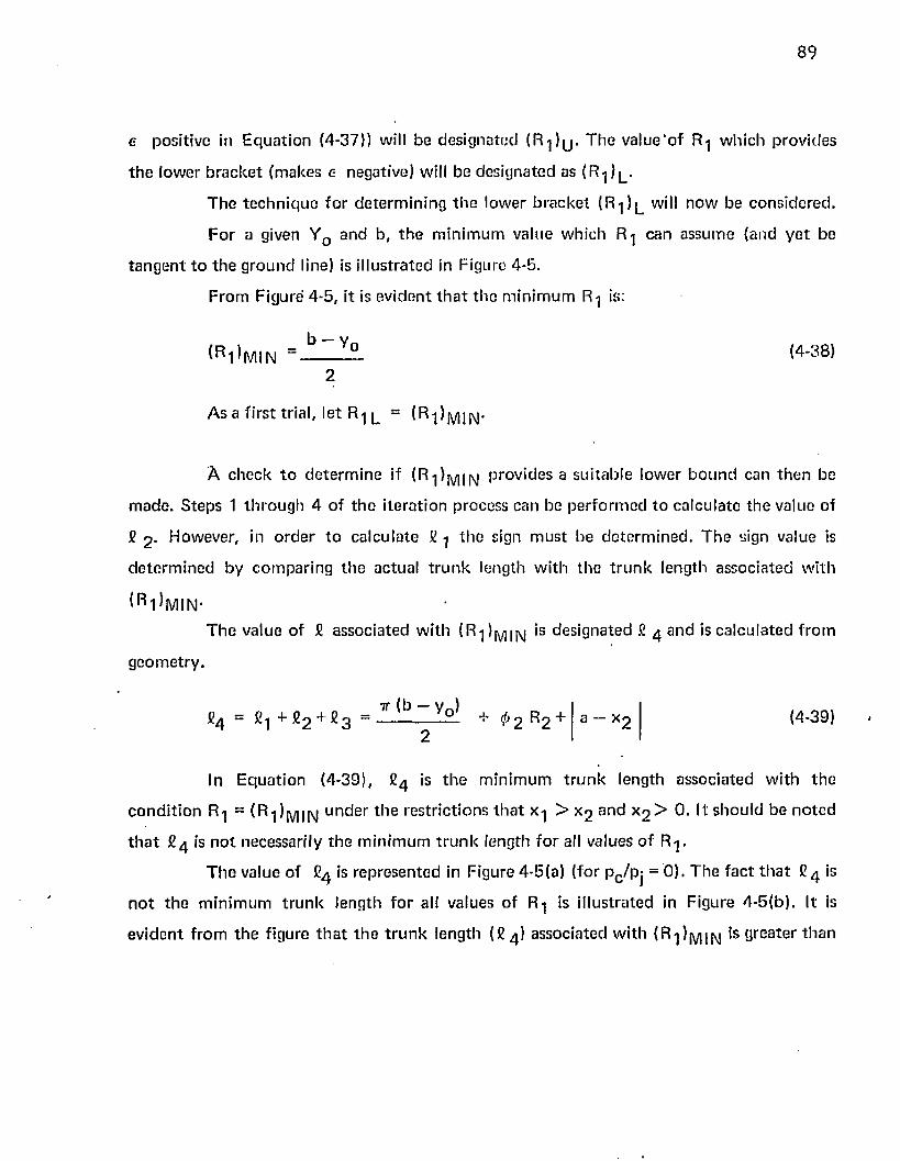
89
e positive in E q u a t io n (4-37)) will be d es igna ted ( R ^ y T h e v a lu e 'o f R-j w h ich p rov ides
th e low er b ra c k e t (m akes e negative) will b e d es igna ted as ( R - j ) y
T h e te c h n iq u e fo r d e te rm in in g th e low er b ra c k e t ( R- j ) l will n o w be co n s id e red .
F o r a given Y 0 an d b , t h e m in im u m value w hich R-j can assum e (and y e t be
ta n g e n t t o th e g ro u n d line) is i l lu s tra ted in Figure 4-5.
F ro m Figure 4-5 , it is ev id en t t h a t th e m in im u m R-j is:
( R ^ m i n ■ b ~ Y ° <4 -3 8 >2
A s a f irs t tria l, le t R-j l =
A c h e ck t o d e te rm in e if ( R i ) mI N Pro v 'd es a su itab le low er b o u n d can th e n be
m ad e . S teps 1 th ro u g h 4 o f th e i te ra t io n p rocess can be p e r fo rm e d to ca lcu la te th e value of
£ 2 - However, in o rd e r to ca lcu la te £ -j th e sign m u s t b e d e te rm in e d . T h e sign value is
d e te rm in e d by co m p a r in g th e ac tual t r u n k length w ith th e t r u n k length assoc ia ted w ith
( R i )m i n -T h e va lue o f £ a ssoc ia ted w ith ( R -])m 11\| is d es igna ted £ 4 a n d is c a lcu la ted f ro m
g e o m e try .
7f ( b — w )E4 = £-| + £ 2 + 2 3 “ --------------— -i- 0 2 R 2
2a — x2 (4-39)
In E q u a t io n (4-39), £ 4 is t h e m in im u m t r u n k length assoc ia ted w ith th e
c o n d i t io n R-j = ( R ■])j\/]IN uncier ti "1 6 res tr ic t ions t h a t x-j > X2 an d X2 > 0 . It s h o u ld b e n o te d
t h a t £ 4 is n o t necessarily th e m in im u m t ru n k length f o r all values o f R-j.
T h e value of £ 4 is rep re sen te d in Figure 4 -5(a) (fo r pc /p j = 0 ) . T h e f a c t t h a t £ 4 is
n o t t h e m in im u m t r u n k leng th fo r all values o f R-j is i l lu s tra ted in F igure 4 -5 (b ) . It is
e v id e n t f ro m t h e figure t h a t t h e t r u n k leng th (£ 4 ) a ssoc ia ted w ith ( R ^ m i n *s 9 rea te r t ' i an
£4 = & 1 + £ 2 + £ ;
( R , ) mi n
MOTE: ( R ^ m i n d o e s n o t a l w a y s c o r r e s p o n d t o ( £ \n
£ A < £ 4
O m ) b >(?M) m i n £ e > j £ 4
in
(d)PHYSICAL REPRE SEN TA TIO N O F £< (b ) P H Y S I C A L REPRESENTATION OF VARIOUS VALUES OF R,
I LLUSTRATION O F M I N I M U M T R U N K LENGTH
FIGURE 4 - 5
sOo
91
t h e t r u n k length ( £ ^ ) associa ted w ith (R - |) / \ . F u r th e r , w henever x^ > a , th e n 32 > fo r all
values o f R^ > ( Ft-])jviIN* ^ ' s co r |d i t ion iS i llustrated b y th e con figu ra t ion w ith radius
( R j l g in Figure 4-5(b).
A s illus tra ted above, th e value of ( R ^ m i n *s a sa tis fac to ry low er b ra c k e t fo r the
so lu t io n if 32 > £ 4 an d x-j > ln f h ' s case X 1 ^ a * anci s '9n ' n E qua tion (4-36) is plus.
T h e u p p e r b rac k e t fo r th e co n d it io n £ > £ 4 m ay be fo u n d fro m th e g eo m etry of
Figure 4-6. This f igure show s th e m ax im u m value o f possib le fo r given values o f a, b, arid
£.
T h e length o f th e ch o rd be tw een c o o rd in a te s (o,o) and (a,b) in Figure 4-6 m ay be
w r i t te n in te rm s o f th e radius and central angle o r in te rm s of th e rec tangu lar coo id iiv ites . If
t h e tw o express ions are eq u a ted , th e result is:
= 2 R-j s i n ^ l
2
F u r th e r , t h e radius, arc length and central angle are re la ted as fo llows:
These tw o re la tionsh ips m ay be c o m b in e d to give a re la tionsh ip fo r R-j..
^ / a 2 + b 2 , „R-i sin — “ = (4-40)
2R 1 V 4.E q u a t io n (4-40) m ay be solved num erica lly to give th e u p p e r b rac k e t (R- j )y fo r
th e c o n d i t io n £ > £ 4 .
I t is n o w necessary t o consider t h e u p p e r a n d low er b racke ts fo r th e c o n d it io n £
< £4 . T w o cases a re possible. T he f irs t is th e c o n d it io n x-j < ^ T h e second is th e
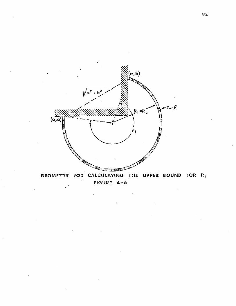
G E O M E T R Y F O R C A L C U L A T I N G THE U P P E R B O U N D FOR FI,
F I G URE 4 - 6
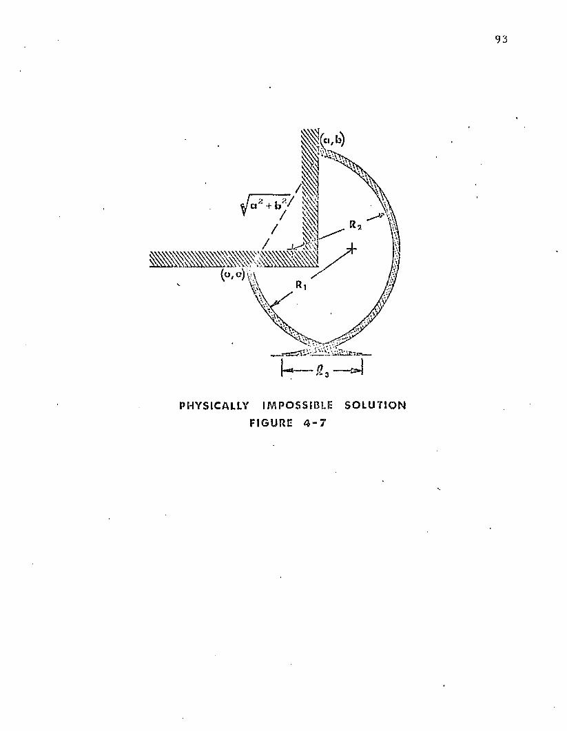
Ji* j? j ■— ■ c^ j
PHYSICALLY I M P O S S I BL E S O L U T I O N
FI GURE 4 - 7
94
cond it ion x^ > In th e first c a se / th e cond it ion show n in Figure 4-7 exists. This case is of
no practical in terest and will n o t be considered.
4-5(b) it is evident th a t x-j < a. Therefore, in this case, th e sign in E quation (4-36) is minus.
F urther , ( R ^ m i n is n o t a satisfactory lower b racke t fo r the so lu tion of E quation (4-37). In
th is case, th e correc t value of £ lies be tw een the configuration represented by (R-j)/^ and
( * 1)IV!IN ' n Ir i9ure 4-5(b). Therefore , u n d e r these cond it ions , (R-j)fyj|[\] = ( R ^ u fo rm s a
sa tisfac to ry upper bound.
It is necessary to establish a d iffe ren t criteria fo r th e lower b racke t (R-j )|_ fo r th e
cond it ion C < and x-j > X2 - The mi n i mu m value possible fo r £ fo r given values of a, b,
pc , pj, and YQ is reached when £ 3 = o in E quation (4-31). This occurs w hen x^ = X2 * The
value of R-j for the cond it ion x-j = X2 establishes the lower b racke t fo r the so lu tion to
E quation (4-36). This value occurs be tw een th e values of x-j = 0 and x-j = a.
The lower b racke t m ay be fo u n d by setting E quation (4-36) equal to zero and
solving fo r R^. The result is:
If, on th e o th e r hand, £ < £ 4 and x-j > X2 , th en from the geom etry o f Figure
Numerically the upper b racket for x>j = X2 is:
(4-41)
2
( R , = a 2 + b 2 + y 0 2 - 2 y p b
2 ( b - y 0 )
(4-42)
Using iterative numerical techn iques (Mueller's m ethod) it is n o w possible to solve for th e
R-j associated w ith Xi = X2 - This R-j is th en taken as ( R^ J y w hich is required to provide a
so lu tion to the system of equa tions which define the non-equilibrium t ru n k shape.
95
4 .6 T runk Cross-Scctional Area
T he cross-sectional area o f th e free and loaded t ru n k shapes are show n in Figures
4-1 and 4-2 respectively. T he cross-sectional area o f the loaded t ru n k shape (Figure 4-2) has
been divided in to five regions which are designated by Rom an numerals. The areas of each
o f these regions m ay be calculated as follows:
(1) Region I is th e area of th e sector o f the circle w ith radius R 2 and
central angle 0 2 less area ° f ^ ie triangle w ith vertices a t coo rd ina tes
<o,o), (x 2, y 2 > and (x2 , o).
A , = R 2 2 - I H I ! (4-431
(2) Region II is th e area o f the rectangle with corners a t coo rd ina tes (X2 ,
o ) , ( x ^ o ) , ( x , , y 0 ) and (x2 , y 0 ).
A n = - £ 3 y 0 (4*44)
(3) Region III is th e area of th e sec to r of th e circle with radius R-j and
central angle <f> .
A, 1 , R , 2 (4-45)
2
(4) Region IV is th e area o f th e rectangle with corners a t coo rd ina tes (a, o),
(x-j, o), (x 1 , y-j) and (a, y - |).
A IV = “ a)Vl (4-46)
96
(5) Region V is t h e area o f th e tr iangle w ith vertices a t c o o rd in a te s (a, b ) ,
(x-j, y-j) and (a, y-j).
A v * J _ (x-j - a) (b ~ y- j ) (4-47)
2
T h e to ta l c ross-sec tional area m ay be d e te rm in e d b y sum m ing th e five a reas given
b y E q u a t io n s (3-43} th ro u g h (3-47). T h e resu l t fo r th e L oaded T ru n k S h a p e is:
R 1 2
2 2 2
+ ( x-j - a)y-j + 1 (x-j - a) (b - y-j) £4-48)2
F or t h e Free T ru n k S hape , t h e cross-sectional area m ay be derived b y sim plify ing
E q u a t io n (4-48). A c o m p a r iso n o f F igures 4-1 an d 4-2 show s th a t fo r t h e Free T ru n k S hape
t h e fo llow ing s im p lif ica tions are possib le:
£ 3 = °
* 1 = * 2 = x o
*
T h e above s im p lif ica tions w h e n app lied t o E q u a tio n (4-48) give an e x p ress ion fo r
t h e cross-sectional area o f th e Free T ru n k S hape . T h e resu lt is:
(Aj)free R 2 2 - H s U l + ^ 1 H L + (x0 - a ) y i2 2 2
+~2 {x° - a)(4-49)
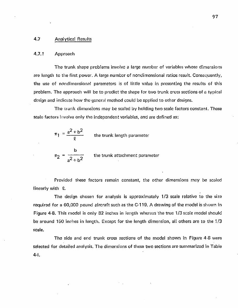
97
4.7 Analytical Results
4.7 .1 A p p ro a c h
T h e t r u n k shape p ro b le m s involve a large n u m b e r o f variables w h o se d im en s io n s
a re leng th to t h e f irs t pow er . A large n u m b e r o f n o n d im ens iona l ra t io s result. C o n se q u e n tly ,
th e use o f n h n d im e n s io n a l p a ra m e te rs is o f lit tle va lue in p resen ting th e resu lts o f th is
p ro b le m . T h e a p p ro a c h will be to p re d ic t t h e shape fo r tw o t r u n k cross sec t ions o f a typ ica l
design and ind ica te h o w th e genera) m e th o d cou ld be app lied t o o th e r designs.
T h e t r u n k d im e n s io n s m ay b e scaled by ho ld ing tw o scale f ac to rs c o n s ta n t . T hese
scale f a c to rs involve o n ly th e in d e p e n d e n t variables, an d are de f ined as:
_ -p- -I- b ^7r-| ----- ------- t |ie t r u n k length p a ra m e te r
b7 r 2 = ^ ie t r u n '< a t t a c h m e n t p a ra m e te r
a i- b
Prov ided th ese f a c to rs rem a in c o n s ta n t , t h e o th e r d im en s io n s m a y be scaled
linearly w ith C.
T h e design chosen fo r analysis is a p p ro x im a te ly 1 /3 scale relative t o t h e size
req u ired fo r a 6 0 ,0 0 0 p o u n d a irc ra f t such as t h e C-119. A draw ing o f th e m odel is sh o w n in
F igure 4-8. Th is m odel is o n ly 82 inches in leng th w hereas t h e t ru e 1 /3 scale m o d e l sh o u ld
be a ro u n d 150 inches in leng th . E x c e p t fo r t h e leng th d im e n s io n , all o th e r s a re t o th e 1 /3
scale.
T h e s ide an d en d t r u n k cross se c t io n s o f th e m odel sh o w n in Figure 4 -8 w ere
se lec ted f o r d e ta i le d analysis. T h e d im e n s io n s o f these tw o sec t ions a re su m m a riz ed in T ab le
4-1.
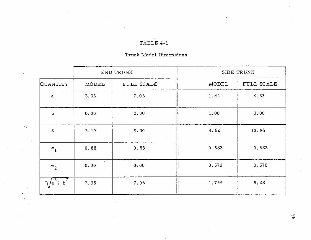
TABLE 4-1
Trunk M o d e l D i m e n s i o n s
E N D TRUNK SIDE TRUNK
Q U A N T IT Y M O D E L F U L L SC A L E M O D E L ■ F U L L SC A L E
a 2. 35 7. 06 1 . 4 4 4. 33
b 0 . 0 0 0. 00 1 . 0 0 3. 00
I 3. 10 9. 30 4. 62 13. 86
*1 0. 88 0. 88 0 . 382 0. 382
*2 0 . 0 0 0 . 00 0. 570 0. 570
V A2. 35 7. 06 1. 755 5. 28
ooo
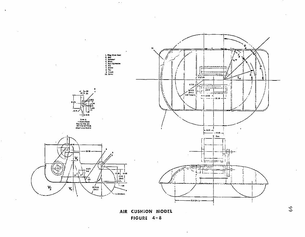
1. WfettnaMAwy i , futittwr 4 , P U il1 D*<t «. &3>7 , S f t t r 1. J*rt 9. T n s X
19. C c -* r
a
n» a4 TlBM OllM Tfpif li fw AH
Of T rw fc A tt« J ,3*>t0fc2» 'd
13.00 j 14.00
I 10.09 I \ \ tft*04 0
1.00
I
» .3R / {R«M Cfld Tl tr»»t U 00
m
AIR CUSHI ON MODEL
FIGURE 4 - 8
vO
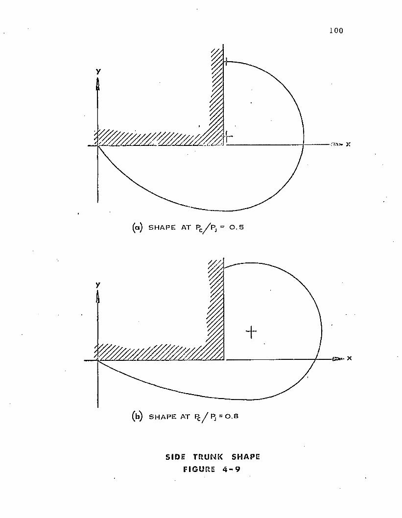
100
( a ) S H A P E AT Pc/ P s ~ O. S
( b ) S H A P ES H A P E AT Pc / P, = 0 . 8
S I D E T R U N K S H A P E
F I G U R E 4 - 9
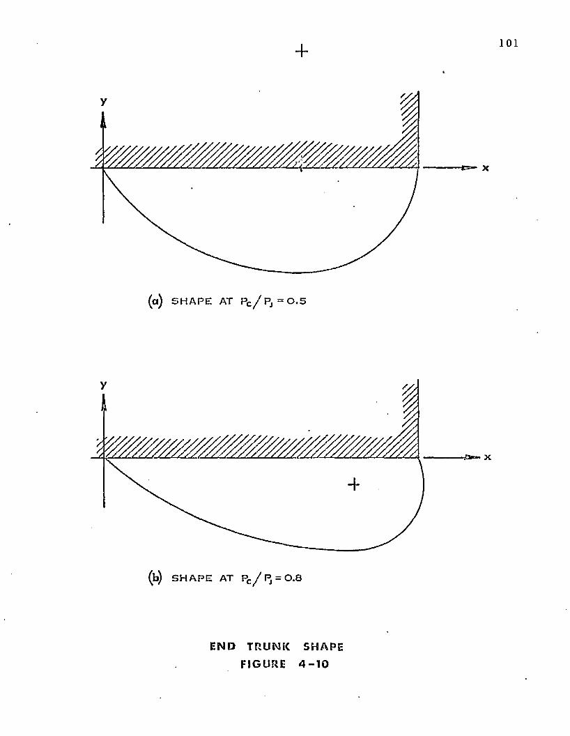
101
-e=- x
(a ) S H A P E AT Pc / P j = 0 . 5
(b) S H A P E AT Pc / P j = 0 . 8
E N D T R U N K S H A P E
F I GURE 4 - 1 0
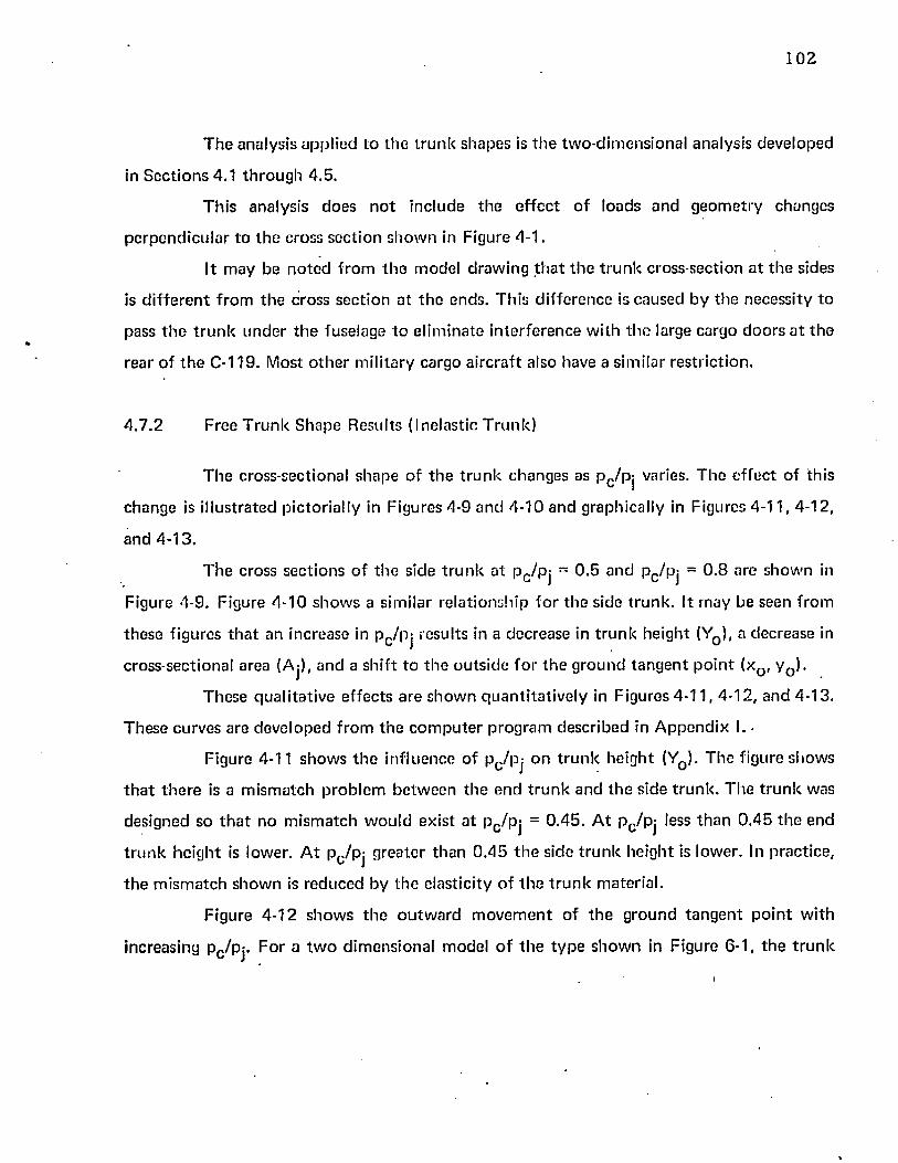
102
T h e analysis app lied t o t h e t ru n k sh ap es is t h e tw o-d im ensiona l analysis deve loped
in S e c t io n s 4.1 th ro u g h 4 .5 .
T h is analysis d o es n o t inc lude th e e f fe c t o f loads an d g e o m e try changes
p e rp e n d icu la r to th e cross se c t io n s h o w n in Figure 4-1.
It m ay be n o te d f ro m th e m odel d raw ing t h a t t h e t ru n k cross-sec tion a t t h e sides
is d i f f e re n t f ro m th e cross sec t ion a t t h e ends . Th is d i f fe re n c e is caused by th e necess ity to
pass t h e t r u n k u n d e r th e fuse lage to e l im ina te in te r fe re n c e w ith t h e large cargo d o o rs a t th e
rear o f t h e C-119. Most o th e r m il i ta ry cargo a irc ra f t also have a s im ilar res tr ic tion .
4 .7 .2 Free T r u n k S h ap e R esults (Ine las tic T ru n k )
T h e cross-sectional shape o f t h e t ru n k changes as p c /pj varies. T h e e f fe c t o f th is
change is i l lu s tra ted p ic to r ia l ly in Figures 4-9 an d 4 -10 a n d graphically in Figures 4 -11 , 4-12 ,
an d 4 -13 .
T h e cross sec t ions o f t h e side t r u n k a t p c /p j = 0 .5 an d Pc/Pj = 0 .8 are sh o w n in
Figure 4-9. F igure 4 -1 0 sh o w s a s im ilar re la t io n sh ip fo r th e side t ru n k . It m ay be seen f rom
th ese figures t h a t an increase in p c/p j results in a decrease in t ru n k he igh t (Y0 ), a decrease in
cross-sec tional area (Aj), a n d a sh if t to th e o u ts id e fo r t h e g ro u n d ta n g e n t p o in t (xQ, y D).
T hese q u a li ta t iv e e f fec ts a re s h o w n q u a n t i ta t iv e ly in F igures 4 -11 , 4 -12 , an d 4-13 .
T hese curves are dev e lo p ed f ro m th e c o m p u te r p ro g ram descr ibed in A p p e n d ix I. •
Figure 4-11 sh o w s t h e in f luence o f p c /p j o n t r u n k he igh t (Y0 ). T he figure show s
t h a t th e r e is a m ism atch p ro b le m b e tw e en th e end t r u n k an d th e s ide t ru n k . T h e t r u n k was
designed so t h a t n o m ism atch w o u ld ex is t a t pc /p j = 0 .4 5 . A t p c/p j less th a n 0 .4 5 th e en d
t r u n k h e ig h t is lower. A t pc /p j g rea te r th a n 0 .4 5 t h e side t r u n k he igh t is low er. In p rac t ice ,
t h e m ism a tc h s h o w n is red u c e d by th e e las t ic ity o f th e t r u n k m ateria l.
F igure 4 -12 sh o w s th e o u tw a rd m o v e m e n t o f th e g round ta n g e n t p o in t w ith
increasing pc /p j. F o r a t w o d im ens iona l m odel o f th e t y p e s h o w n in F igure 6-1, t h e t r u n k
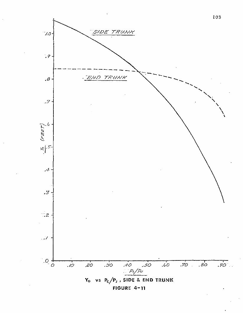
Yo (F
SE
T)
103
S J D Y P T 'tf& A 'A '
. AS/V/D TPi/A Y/Y
.70 .80.30O ./Op c / p *
Yo v s Pc/ P j , SIDE & END TRUNK
FIGURE 4 - 1 1
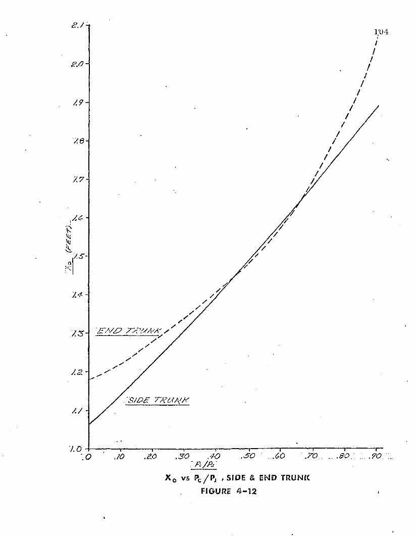
y.8-
A 6 -
/.s -
7.3 ~ s
.50: o
x o vs P c / P j f S I DE & END TRUNK
FIGURE 4 - 1 2
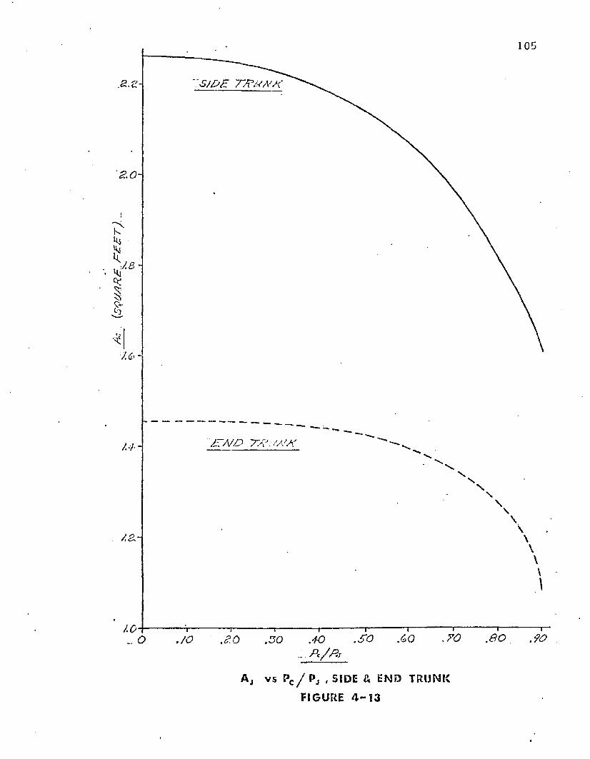
105
:sj£>£ TSM A 'S
JJ7A/D ? X J, .V /A
1 0.60.SO
Aj v s Pc / P j , SIDE & END TRUNK
FIGURE 4 - 1 3
I106
ends a re u n c o n s tra in e d a n d th e ta n g e n t p o in t is f re e to m ove o u tw a rd . H ow ever, fo r a th re e
d im ensiona l m odel o f th e ty p e sh o w n in Figure 4-8 , no f ree edges ex is t an d th e t r u n k
m ateria l m u s t s t r e tc h t o p e rm i t o u tw a rd m o v e m e n t o f t h e g ro u n d ta n g e n t . T h e ac tu a l t r u n k
m ateria l env is ioned fo r use o n an a ir cu sh io n landing sy s tem w o u ld be h ighly e las t ic (300%
s tre tc h ) . C o n s e q u e n t ly , cons ide rab le m o v e m e n t o f x Q s h o u ld be p e rm i t te d , a n d th e
tw o -d im en sio n a l p red ic t io n s sh o u ld be reasonab le .
F igure 4 -1 3 sh o w s th e va ria tion in cross-sectional a rea w ith p c /pj as p red ic te d by
E q u a t io n (3 -48). T h e curve sh o w s rela tive small area varia tion be low p c /p j = 0 .5 a n d large
va r ia t ion above pc /p j = 0 .5 .
4 .7 .3 Free T r u n k S h a p e R esu lts (E lastic T ru n k )
T h e e f fe c t o f using an elastic m ateria l fo r th e t r u n k was investiga ted using th e
c o m p u te r p ro g ram descr ibed in A p p e n d ix III. T h e t r u n k m ate ria l envis ioned is a ru b b e r a n d
n y lo n lam in a te . T h e n y lo n is lam in a te d in a s lack c o n d i t io n so t h a t it do es n o t c a rry load
un til t h e ru b b e r has e x te n d e d by a t least 100% . A typ ica l e las t ic curve f o r such a m ateria l is
sh o w n in F igure 4 -1 4 . T h e m ateria l was se lec ted so t h a t a t t h e design p o in t ( e = 0, pc /pj =
0 .5 , pj = 8 0 psfg) th e leng th o f th e e lastic side t r u n k was equa l t o th e length o f th e inelastic
side t r u n k a n d th e resu lting shapes w ere identica l. T h e e f fec ts o f changing pc /p j a n d pj on
th e s h a p e o f t h e s ide t r u n k a n d th e en d t r u n k c o n s tru c te d f ro m th e e las tic m ateria l
descr ibed by Figure 4 -1 4 w ere eva lua ted . T h e results a re p resen ted in F igures 4 -1 5 th ro u g h
4-20.
F igure 4 -1 5 sh o w s t h e e f fe c t o f Pc /p j on th e t r u n k length . T h e e f fe c t o f a 50%
increase o r dec rease in t h e design p ressu re is also sh ow n . T h e figure sh o w s t h a t t h e t r u n k
length decreases w i th increasing pc /p j. T h e f igure also show s t h a t t h e t r u n k p ressu re has a
large in f lu en ce on th e t r u n k leng th . T h e t r u n k m ateria l has a s lack length o f a b o u t 1.4 fee t .
A t pj = 8 0 psfg, t h e length has e x te n d e d t o a ro u n d 4 .9 feet. T h is large leng th change a llow s
th e t r u n k t o e las tica lly r e t r a c t a f t e r t a k e o f f to red u ce a e ro d y n a m ic drag.-
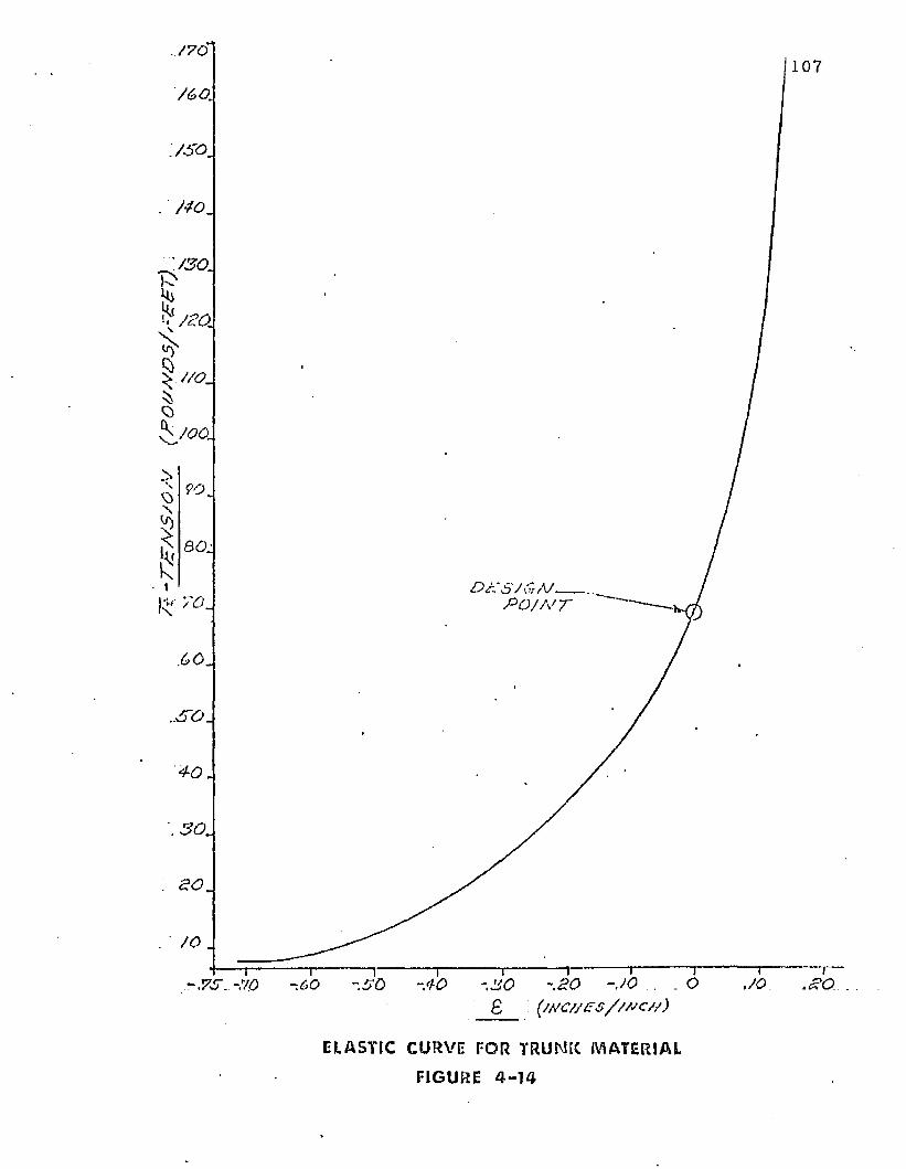
107
/O .
JO-JO -JO -30 .SO -JO . .£ ( / J C / f f s / z / s c / / )
-60
ELASTIC CURVE FOR TRUNK MATERIAL
FIGURE 4 - 1 4
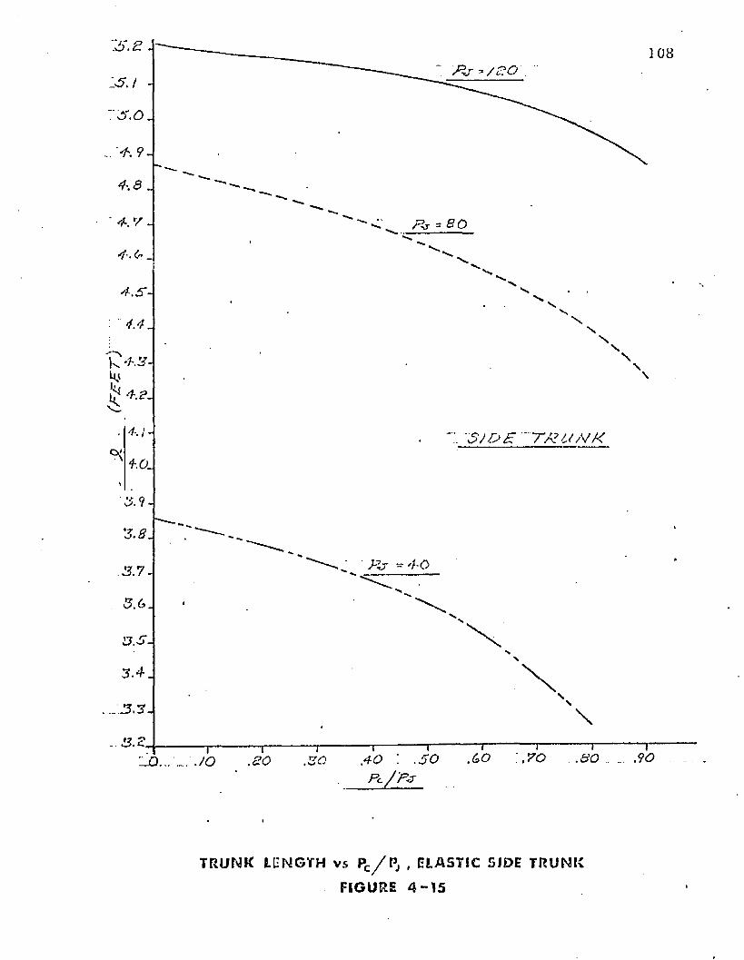
1 0 8
' $ / £ > £ ' T X t O V K
V
.30.SO
T R U N K L E N G T H v s Pc/P j , ELASTI C SIDE T R U N K
FI GURE 4 - 1 5
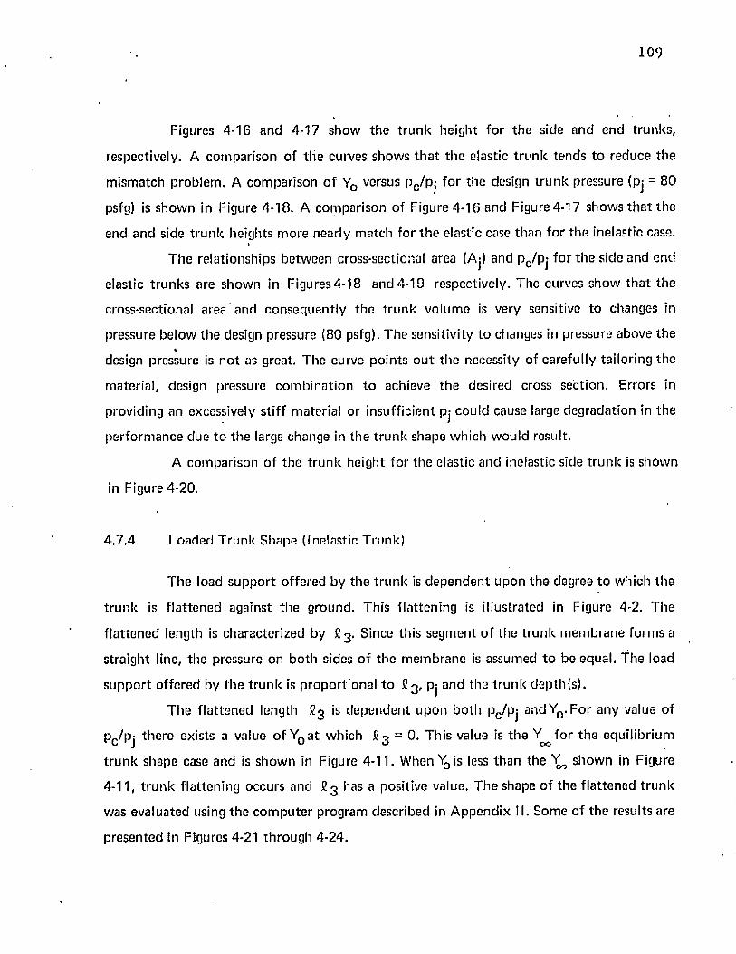
109
Figures 4-16 a n d 4-17 sh o w th e t ru n k heigh t fo r th e side and end t runks ,
respectively. A com parison o f t h e curves show s th a t th e elastic t ru n k tends to reduce th e
m ism atch prob lem . A com parison o f Y0 versus p c/p j fo r th e design t ru n k p ressure (pj = 80
psfg) is show n in Figure 4-18. A com parison of Figure 4 -16 and Figure 4-17 show s th a t th e
end and side t ru n k heights m ore nearly m atch fo r th e elastic case th an fo r th e inelastic case.
T he re la tionships be tw een cross-sectional area (Aj) and pc /p j fo r th e side and end
elastic t ru n k s are show n in F igu res4 -18 and 4-19 respectively . T he curves show t h a t th e
cross-sectional area and c o nsequen tly th e t ru n k vo lum e is very sensitive to changes in
pressure be low th e design pressure (80 psfg). T he sensitivity to changes in pressure above th e%
design pressure is n o t as great. T he curve po in ts o u t th e necessity of carefu lly tailoring th e
m ateria l, design pressure co m b in a t io n to achieve th e desired cross section . Errors in
providing an excessively s t i f f m aterial o r insuff ic ien t pj cou ld cause large deg rada tion in th e
pe rfo rm an ce due t o th e large change in th e t ru n k shape w hich w ou ld result.
A com parison of th e t ru n k heigh t fo r th e elastic and inelastic side t ru n k is show n
in Figure 4-20.
4 .7 ,4 Loaded T ru n k S hape (Inelastic Trunk)
T h e load s u p p o r t o ffe red by th e t ru n k is d e p e n d e n t upon th e degree to which th e
t ru n k is f la t te n e d against th e g round . This f la t ten ing is i llustra ted in Figure 4-2. T h e
f la t te n e d length is charac te r ized by £ 3 . Since th is segm en t o f th e t ru n k m em b ran e fo rm s a
s tra igh t line, th e pressure on b o th sides o f th e m em b ran e is assum ed t o be equal, t h e load
s u p p o r t o ffe red by th e t ru n k is p ro p o rt io n a l t o fi3 , pj and th e t ru n k d ep th (s ) .
T he f la t ten ed length 6 3 is d e p e n d e n t u p o n b o th pc/p j and YQ. For any value o f
pc /pj th e re exists a value o f Y0 a t w hich J23 = 0. Th is value is t h e Y ^ f o r th e equ ilibr ium
t ru n k shape case and is show n in Figure 4-11. W hen ^ i s less th a n the show n in Figure
4-11, t r u n k f la t ten ing occurs and £ 3 has a positive value. T h e shape o f th e f la t te n e d t ru n k
was eva lua ted using th e c o m p u te r program described in A p p e n d ix II. S om e o f th e results are
p resen ted in Figures 4-21 th ro u g h 4-24.
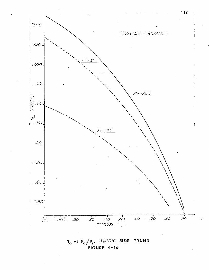
11 0
1 0 0 J
. s o: o
Yo vs Pc / Pj ' ELASTIC SIDE TRUNK FIGURE 4 - 1 6
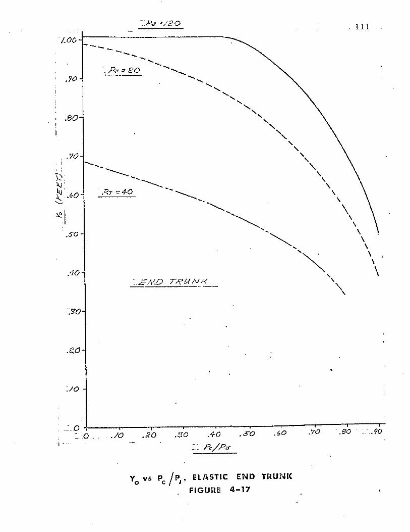
' J 2 0 111
90 A
t p u n h
so
Yo v s P c / P j ’ ELASTI C e n d t r u n k
. F I GU R E 4 - 1 7
(5Q
WX
E
FZ
ST
)
'2.4 -
7.0 -
V:ao -
.70JO•i
A v s P / P . , ELASTIC SIDE T R U N K j C / J
FIGURE 4 - 1 8
A 70-
sco JO .a o . 7 0
AJ v s Pc / P j , ELASTIC END TRUNK
FIGURE 4 - T 9
(FF
FT
j. F A . S S F / C - 3 ^ = 3 0
. . .S JJO F
/A/FAS ST/C
90 -
.80-
.50
3 0.70 .90.BO.50O 30JO «
P / B
Yo v s P c / P j ’ C0MPAR150E\« OF RESULTSFIGURE 4 - 2 0
115
Figure 4-21 show s th e re la tionsh ip b e tw een £ 3 and Y 0 /Y oo a t various pc/pj
values fo r th e side t ru n k . Figure 4-22 show s th e sam e rela tionsh ips fo r th e end t ru n k . T he
slope o f t h e £ 3 versus Y q /Y ,^ curve is p ro p o rt io n a l to th e stiffness. T h e curves sh o w th a t
th e s tiffness of b o th t ru n k shapes is nearly linear fo r de flec tions up to 50% o f th e free t r u n k
he igh t ( Y ^ ) .
Figures 4-23 and 4 -24 sh o w th e re la tionsh ip be tw een Aj and Y q / Y ^ fo r th e side
an d end t r u n k respectively. T h e values of Aj w ere p red ic ted by E quation (3-48).
116
s w £ r 7v?m ,v a
\ \
. 9 0 -
n / / o = o .o
= 0 . 3
= 0 .5 7
= . 0 , Y
= 0.8
■A
a ?. 4 0 -
7 0 -
yo ...(SO . ?0 .4 0 .50 .GO .70 .SO ,90 , / . o o .o
m v s \ ,/ 0 ’ S ,D E T R U N KFIGURE 4 - 2 1
117
;■ f a / d r /?u A > x
:p - M = o . r ■ = o.e ■= 0.9= ~ a 9 5
j.oo-\
.ao .30 .<3? .50A o /K ^ t
-^3 vs Yo / Yac - END-TRUNKFIGURE 4 - 2 2
(SQ
UA
RE
. RE
E7)
118
"SADR RRUAAR
0 .5
1.90 ■ ■/& — o .v
/.ro
A 6 0 ■
0.9
A OO.AO .SO * W
A v s Y / Ym , SIDE T R U N KJ O I CO ’
FIGURE 4 - 2 3
y.so-\
AAO
/SO-
/.'SO-
^ A/0-
*^ 100 k
§O‘ SO-
sj~.7S0
.7 0
,60
.SO
AO-
. 3 0
. 20 -
J O -
119Z3/V/3 AA‘6<A/A
A c /A - O . /S
W /
—r~. / o 20 .30 <h0 . .SO
. ) r. / YonAO. .70 .SO .......90. A00
A J v s Y o / Y c o ’ E W D TE>‘ U N K
FIGURE 4 - 2 4
5. ANALYSIS OF DISTRIBUTED JET FLOW
5.1 In t ro d u c t io n
T h e Air C u sh ion L and ing S y s tem in tro d u c e s air t h r o u g h o u t a large area o f th e
b o t to m o f t h e t r u n k in o rd e r to p rov ide " a i r lu b r ic a t io n " t o t h e t ru n k . Th is " a i r
lu b r ic a t io n " is necessary t o p re v e n t excessive w ear o f th e t r u n k d u r ing ta k e o f f ro ta t io n and
landing flare. D uring these m aneuvers , th e cu sh io n p ressure a p p ro a c h e s a tm o s p h e r ic p ressure
a n d th e t r u n k m u st c a rry a p o r t io n o f th e load.
F o r t h e A C LS, t h e pe riphera l je ts are fo rm e d by a large n u m b e r o f s lo ts o r holes
w hich a re d i s t r ib u te d over th e b o t to m o f th e t ru n k . T h e A ir Cushion Vehicle , on t h e o th e r
h and , n o rm a l ly e m p lo y s a o n e c o n t in u o u s nozz le w h ich c o n c e n t ra te s th e single je t a t th e
p o in t o f m in im u m day lig h t c learance . Because o f th ese d iffe rences , m o d if ic a t io n s o f th e
c o n c e n t ra te d je t th e o r ie s a rc necessary w h en a pp ly ing th e m t o t h e d is t r ib u te d je t sy s tem .
In th is C h a p te r , m o d if ic a t io n s t o t h e c o n c e n t ra te d je t th eo r ies p re se n te d in
C h a p te r 2 have been deve loped . These m o d if ic a t io n s a llow th e c o n c e n t ra te d je t th e o r ie s to
m o re c lose ly c o n fo rm t o th e ac tua l A ir C ush ion Landing S y s tem d is t r ib u te d je t design.
T w o cases have been c o n s id e red : T h e D is tr ibu ted J e t M o m e n tu m T h e o ry an d th e
F low R e s t r ic to r T h e o ry .
T h e D is tr ib u ted J e t M o m e n tu m T h e o ry applies th e m o m e n tu m th e o r ie s
dev e lo p ed in C h a p te r 2 t o a n u m b e r o f je ts in series. T h is th e o r y assum es t h e cush ion
pressu re is m a in ta in e d by th e change in m o m e n tu m o f th e p e r ip h e ra l je t . T h e m o m e n tu m
th e o r y is d e v e lo p e d in S e c t io n 5 .2 .
T h e F low R e s tr ic to r T h e o ry app lies th e p le n u m th e o r y t o t h e t r u n k c o n f ig u ra t io n
f o r t h e A ir C ush ion L anding S y s tem . This th e o r y assum es th e cu sh io n p ressu re is m a in ta in e d
b y a f lo w re s t r ic t io n a t t h e cu sh io n p e r ip h e ry . T h e F low R e s tr ic to r T h e o ry is d eve loped in
S e c t io n 5 .3 .
120
T h e sy m bo ls are as follows:
a x c o o rd in a te o f th e u p p e r t ru n k a t t a c h m e n t po in t , f t
aj to ta l area o f t h e orifices in th e t ru n k , f t^
a n to ta l area o f th e orifices in th e n * * 1 row , f t ^
b y c o o rd in a te of u p p e r t ru n k a t ta c h m e n t po in t , f t
C q cush ion e x h a u s t nozzle shape coeff ic ien t
Cjj coe ff ic ien t of discharge fo r p lenum c h am b erth(Cq Jo f low coeff ic ien t fo r p ressure d is tr ibu t ion a t th e n m
row o f t ru n k orifices
C j effec tive f low area red u c t io n in th e cush ion ex h au st nozzle
caused by th e f low from th e t ru n k orifices
(Cx )n coeff ic ien t o f d ischarge fo r th e n 1-*1 row o f t ru n k orifices
D q t ru n k orifice d iam e te r , f t
d je t he igh t o r t ru n k day lig h t c learance, f t
d n je t he igh t fo r the n ^ 1 row of t ru n k nozzles, f tO
gQ gravitational c o n s ta n t , f t / s e c *1
H a irc ra ft clearance, th e d is tance be tw een th e a irc ra f t hard
s tru c tu re a n d th e g round , f t
Jp th e t o t a l , reac tion f rom th e n1-*1 row o f j e t orifices, lbs
6 partial t ru n k length (see Figure 5-3), f t
^ 2 partial t r u n k length (see Figure 5-3), f t
JZg t ru n k f o o tp r in t length (see Figure 5-3), f t
N n u m b e r o f je t orifices per row
n ' effective n u m b e r o f row s o f jets w hich c o n tr ib u te to cush ion
nozzle area f low red u c tio n
Pg a tm o sp h e r ic pressure, psf
Pc cush ion pressure, psf
t r u n k p ressure, psf
s ta t ic p ressure in th e cush ion e x h a u s t nozz le a t th e n 1 ^ 1
row o f t ru n k orifices, psf
cush ion t o t ru n k p ressure ra t io
f lo w f ro m th e n 1-*1 ro w o f t r u n k orifices, f t^ /s e c
flow f ro m th e p len u m ch am b er , f t^ /s e c
to ta l f lo w f ro m th e t ru n k , ft*Vsec
to ta l f low f ro m all t r u n k orif ices f ro m th e m * * 1 row up to and
including th e n * * 1 row , f t^ / s e c
rad ius o f cu rv a tu re fo r th e t r u n k segm en t £-|, f t
rad ius o f cu rv a tu re fo r th e t r u n k se g m e n t £3 - f t
to ta l leng th o f th e t ru n k , f t
e ffec tive f low length of th e t ru n k , f t
to ta l e ffec tive je t th ickness , f t
effec tive je t th ick n ess fo r th e n ^ 1 row o f orifices, f t
average ve loc ity o f th e gas f ro m th e n ^ ro w o f orifices, f t / sec
average ve locity o f th e gas in th e cu sh io n e x h a u s t nozzle a t th e
n ^ ro w of t ru n k orifices, f t / sec
je t th ic k n e ss p a ra m e te r fo r c o n c e n t ra te d je t
je t th ick n ess p a ra m e te r fo r n 1^ je t
horizontal distance from lower trunk attachm ent point (0,0) to
t r u n k low p o in t (xQ1y 0 ), f t
x c o o rd in a te o f m in im u m je t he igh t p o in t
vertical d is tance f ro m low er t r u n k a t t a c h m e n t p o in t (0 ,0 ) to
t r u n k low p o in t (x 0 ,y 0 ), f t
y c o o rd in a te of m in im u m je t h e ig h t p o in t
value o f Y q at which trunk flattening begins (£3 = 0 ), ft
m o m e n tu m p a ra m e te r d e f in ed by E q u a t io n (5-7)
1Z3
G reek sy m b o ls
0 n angu lar pos it ion o f n ^ 1 row o f orif ices relative to th e vertica l, rad ians
? n angle of n * * 1 o r if ice ro w relative to th e t ru n k , rad ians
5 n he igh t o f n ^ 1 o r if ice ro w above m in im u m ground c lea rance o f t h e t r u n k , f t
° n effec tive je t angle, radians
*n d is tan ce along th e t r u n k f ro m a t t a c h m e n t p o in t (a,b) to th e
n ^ 1 row of orifices, f t
P d e ns ity of th e gas ,Ib /ft^
S u b sc r ip ts
£ firs t row o f orif ices inside th e cush ion
m last ro w o f orif ices inside th e cush ion
n a rb i t ra ry ro w o f orif ices
5 .2 D is tr ibu ted J e t M o m e n tu m T h e o ry
5.2,1 A p p ro a c h an d A ssu m p tio n s
In C h ap te r 2, several theo r ies fo r p red ic ting th e p e rfo rm a n c e o f a periphera l je t air
cu sh io n w ere deve loped . T hese th eo r ie s assum ed t h a t th e pe riphera l je t was fo rm e d by a
single c o n c e n t ra te d s lo t or nozz le a io u n d th e p e r ip h e ry o f th e cush ion . T h e nozzle
co n f ig u ra t io n fo r th e A ir C ush ion Landing S ys tem m ay be c o n s id e rab ly d if fe re n t f ro m th e
a ssum ed c o n c e n t ra te d jet . In pa rt icu la r , th e A C LS utilizes a large n u m b e r of s lo ts o r nozzles
d is t r ib u te d over th e b o t to m p o r t io n o f th e t ru n k . C o n se q u e n tly , it was desirab le t o m o d ify
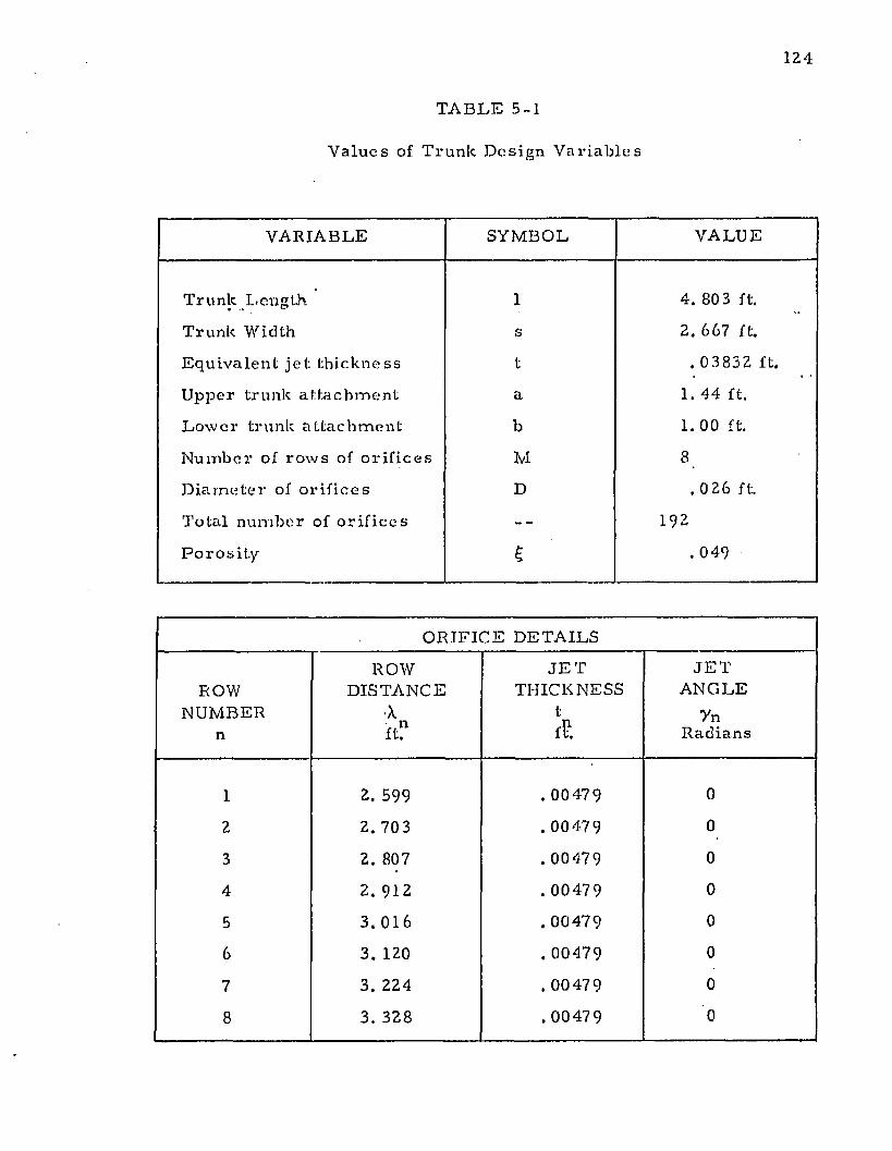
124
T A B L E 5-1
V a l u e s of Tru nk D e s i g n V a r i a b l e s
V A R IA B L E SYM BOL V A L U E
Trunk Length. 1 4. 803 ft.
Trunk Width s 2. 667 ft.
E q u i v a le n t j e t t h i c k n e s s t . 0 3 8 3 2 ft.
U pper trunk a t t a c h m e n t a 1. 44 ft.
L o w e r trunk a t t a c h m e n t b 1 .0 0 ft.
N u m b e r o f r o w s of o r i f i c e s M 8
D i a m e t e r of o r i f i c e s D . 0 26 ft.
T ota l n u m b er of o r i f i c e s 192
P o r o s i t y £ . 0 4 9
O RIFICE D E T A IL S
ROWN U M BER
n
ROWDISTAN C E
Xft"
J E TTHICKNESS
t&
J E TA N G L E
7nRadians
1 2. 599 . 0 0479 0
2 2. 703 . 0 0 479 0
3 2. 807 . 00479 0
4 2. 912 . 0 0479 0
5 3. 016 . 0 0 4 7 9 0
6 3. 120 . 00479 0
7 3. 224 . 00479 0
8 3. 328 . 0 0479 0
125
th e th e o r ie s t o m ore c losely a p p ro x im a te th e A C LS configu ra t ion . In th is sec tion , th e je t
con f ig u ra t io n was assum ed t o be rep resen ted by a series o f c o n t in u o u s slo ts along th e
b o t to m p o r t io n of th e t ru n k . This c on figu ra t ion is i l lus tra ted in Figure 5-1.
T h e general a p p ro ach t o th e p rob lem was to assum e a t ru n k clearance -£.d) fo r
given values o f t ru n k pressure (pj) and recovery pressure ratio (pc /p j) . T h e je t he igh t fo r
each o f t h e t r u n k nozzles was d e te rm in e d f ro m the t r u n k shape p rog ram s deve loped in
C h a p te r 4 . S ta r t in g on th e a tm o sp h e r ic side o f th e t ru n k , th e pressure in c re m e n t across each
je t was ca lcu la ted in succession until th e pressure in th e cushion was d e te rm in e d . If th e
ca lcu la ted a n d assum ed value o f cu sh ion pressure d id n o t agree, th e jet he igh t was ad jus ted
until a g re e m e n t was achieved.
T h e pressure in c re m e n t across each je t is d e p e n d e n t u p o n th e m o m e n tu m th e o ry
assum ed. How ever, w hen th e pressure in c rem en t is small, all of th e m o m e n tu m theor ies
deve loped in C h a p te r 2 give sim ilar results. In view o f th e small pressure increm en ts
associa ted w ith a series o f d is t r ib u ted jets, on ly tw o theo r ies — th e th in je t th e o ry and th e
e x p o n en tia l th e o r y — w ere selected fo r fu r th e r deve lopm en t.
T h e d e v e lo p m en t of th e d is t r ib u ted je t m o m e n tu m th eo ry is similar to th e
c o n c e n t ra te d j.et theo r ies p resen ted in C hap te r 2. T he assum ptions m ade in Sec tion 2.4
app ly to t h e d is t r ib u ted je t system . M oreover, th e a ssum ptions m ade in Sec tions 2 .5 and 2.6
are app licab le w h e n th e th in je t o r th e exponen tia l theo r ies are app lied to t h e d is t r ib u ted je t
sys tem . T w o add it iona l assum p tions are necessary. These assum ptions are as follows.
5 .2 .1 .1 T h e jets are fo rm e d by a series o f c o n t in u o u s slo ts a long th e b o t to m of
th e t ru n k .
5 .2 .1 .2 T h e f low f rom any given je t is re la ted on ly to th e sta t ic pressure
d iffe rence across th e nozzle. T h e e f fe c t o f f low fro m o th e r je ts is
neglected .
D I S T R I B U T E D J ET G E O M E T R Y
F I G U R E 5 - 1
127
5 .2 .2 Force E qu il ib r ium Across t h e Je ts
In S ec tions 2 .4 .6 , 2 .5 .6 , an d 2 .6 .6 fo rce e q u il ib r ium was app lied in th e x d ire c t io n
t o a c o n tro l v o lu m e c o n ta in in g th e periphera l je t . T h e resu lting exp ress ion e q u a te d th e
p ro d u c t o f th e je t he igh t a n d th e p ressure in c re m e n t across th e je t t o th e change of
m o m e n tu m o f t h e je t .in t h e x d ire c t io n . A sim ilar express ion m ay be deve loped fo r each je t
in t h e ce ries 'show n in Figure 5-1.
F orce e q u il ib r ium app lied to t h e f ir s t je t in Figure 5-1 gives:
J id 1 ( P 1 - p a ) = — ( 1 + s I n 0 1 > <5 *1 a >
S
w here 0-| = 7 -j + </>•]
S im ilarly , fo rce equ il ib r im app lied to t h e second je t is:
Jnd 2 fP2 _ [ V = — <1 'l s i n 0 2> t5 *l b )
S
A cross th e nd l je t , fo rce equ if ib rim gives:
J 'd n {Pn - P |l_ 1 ) = J L (1 + sin fln ) (5-1 c)
S
w h ere 0 n = 7 n + 0 n
In general, t h e p ressure a t an y p o in t Pp m ay be fo u n d by rearranging E q u a tio n
(5-1 c).
j 'Pn = _ J1 _ (1 + sin <?n ) + Pn _ i (5-2)
d nS
1
128
T h e value o f J p is d e p e n d e n t u p o n th e f low th e o ry se lec ted . T h e s im ple je t th e o ry
a n d th e e x p o n e n tia l th e o r y are co n s id e red m o s t a p p ro p r ia te fo r t h e d is t r ib u ted je t case.
Both o f th ese th eo r ies a re app licab le to th in jets , and th e d is t r ib u te d je t co n f ig u ra t io n
involves a series o f th in jets.
T h e express ions fo r J p given by th e tw o th in je t th eo r ie s w ere deve loped in
S ec tio n s 2 .5 an d 2 .6 respective ly . W hen app lied to th e n ^ 1 je t in th e series, th e m o m e n tu m
express ions b e c o m e :T h in je t th e o ry
J ’n = 2 S t n (Pj - P n_ 1 ) (5-3a)
E xp o n en tia l th e o ry
j ; = 2 s t n (Pj — Pn—1) ( 1 - e “ 2 Xn) (5-3b)
2X,
w h e re Xn “ _ r]_ (1 + siri 0 n ) (5-4)
d n
T h e m o m e n tu m expressions, E q u a t io n s (5-3a) fo r (5-3b), m ay n o w be c o m b in e d
w ith E q u a t io n s (5-2) and (5-4) t o p ro v id e an express ion fo r th e p ressure across t h e nd l jet.
T h e results are:
T h in je t th e o ry
Pn = 2(Pj - P n_ 1) X n + Pn_ 1 (5-Sa)
E x ponen tia l th e o ry
o vPn = (Pj — Pn —l) ( 1 — e n ) + Pn _ ! (5-5b)
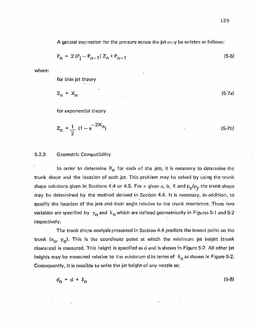
129
A general exp ress ion fo r t h e pressure across th e je t m ay b e w r i t te n as fo llows:
Pn ‘ Z l P j - P ^ l Z ^ - P n — (5-6)
w here :
fo r th in je t th e o ry
2 n = Xn ' (B^a)
fo r e x p o n e n tia l th e o r y
9 VZ n = ± ( 1 ~ e n ) • (5-7b)
2
5 .2 .3 G e o m e tr ic C o m p a tib i l i ty
In o rd e r to d e te rm in e X n f o r each of th e jets, it is necessary to d e te rm in e th e
t r u n k shape and th e lo ca t io n o f each je t . Th is p ro b le m m ay be solved b y using th e t ru n k
shape so lu t io n s given in S ec tio n s 4 .4 o r 4 .5 . F o r a given a, b, i! an d pc /p j , th e t ru n k shape
m ay be d e te rm in e d by th e m e th o d derived in S ec t io n 4 .4 . It is necessary , in ad d it io n , to
spec ify th e loca t ion o f th e je ts a n d th e i r angle relative t o th e t r u n k m em b ran e . These tw o
variables are specif ied b y y n and Xn w hich are d e f in ed geom etrica lly in Figures 5-1 an d 5-2
respectively .
T h e t r u n k shape analysis p re se n ted in S ec tion 4 .4 p red ic ts t h e low est p o in t on th e
t r u n k (xQ, y Q). Th is is t h e c o o rd in a te p o in t a t w h ich th e m in im u m je t he igh t ( t ru n k
clearance) is m easured . T h is h e igh t is specif ied as d and is s h o w n in Figure 5-2. All o th e r jet
he igh ts m ay be m easu red relative to t h e m in im u m d in te rm s o f 5 n as sh o w n in Figure 5-2.
C o n se q u e n tly , i t is possib le t o w r i te th e j e t h e ig h t o f a n y nozz le as:
d n = d + 6 (5-8)
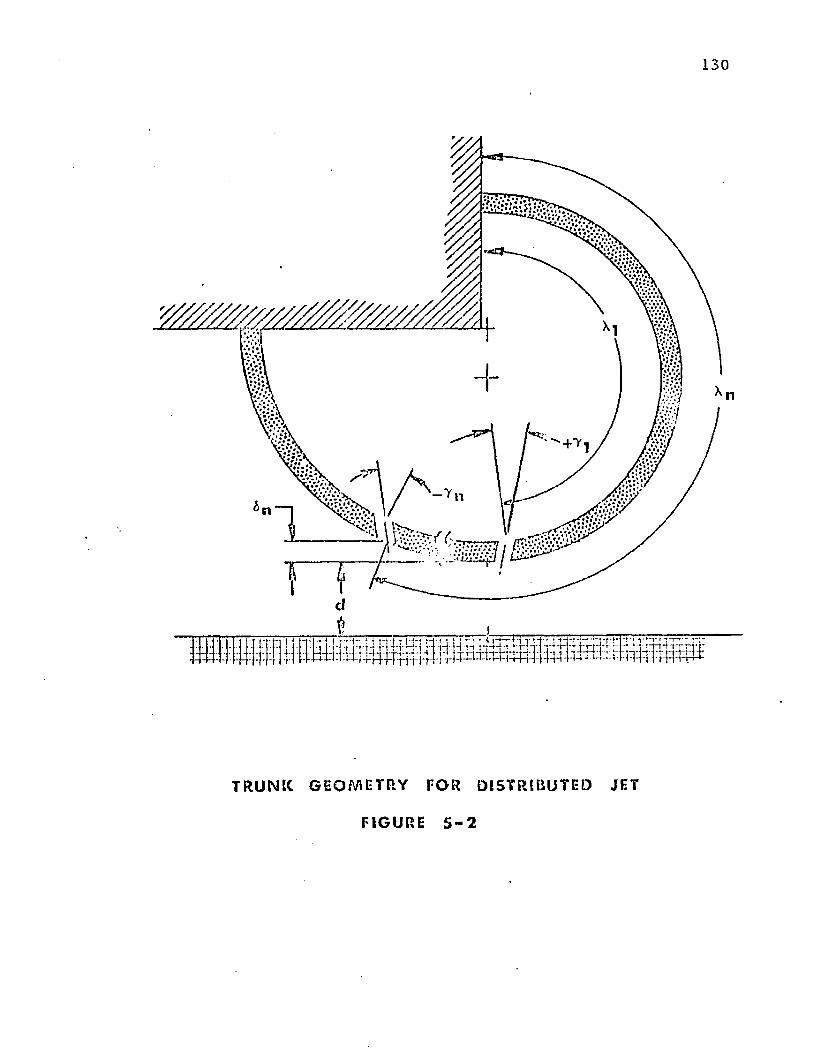
130
t
T R U N K G E O M E T R Y F O R D I S T R I B U T E D JET
F I G U R E 5 - 2
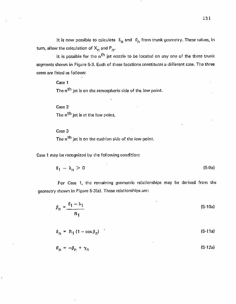
131
It is no w possible to calculate 6 n and 0n from t ru n k geom etry . These values, in
tu rn , allow th e calculation of X R and Pn>
It is possible fo r th e n * * 1 je t nozzle to be located on any one o f the th re e t ru n k
segm ents show n in Figure 5-3. Each o f these locations cons ti tu tes a d iffe ren t case. T he th ree
cases are listed as follows:
Case 1
T he n ^ je t is on th e a tm ospheric side of the low po in t.
Case 2
The n ^ je t is a t th e low po in t.
Case 3
The n * * 1 je t is on the cushion side of the low poin t.
Case 1 m ay be recognized by th e following cond it ion :
- Xn > 0 (5-9a)
For Case 1, th e remaining geom etric relationships m ay be derived from the
geom etry show n in Figure 5-3(a). These rela tionships are:
0 n = £l ~ Xl (5-1 Oa)R 1
6 n = R-j (1 — cos 0n ) ’ (5-11a)
^n + ^n (5-12a)
132
Case 2 m ay b e recogn ized by th e fo llow ing c o n d i t io n :
fi1 + C3 “ K > 0 ^ £ 1 ~ Xn (5-9b)
T h e rem ain ing g e o m e tr ic re la t ionsh ip s as s h o w n in Figure 5-3(b) are:
Pn = 0 (5 -10b)
6 n = 0 (5 -1 1b)
0 n = 7 n (5-12b)
Case 3 m ay be recogn ized by th e fo llow ing c o n d it io n :
h + C3 “ Xn < 0 (5-9c)
T h e rem ain ing g eo m etr ic re la t io n sh ip s as sh o w n in Figure 5-3(c) are :
0 n = Xn ~ g 1 ~ g3 {5. 10c)
R2
6 n = R 2 d -cosj3n) (5 -1 1c)
° n = ^ n + T n (5-12c)
5 .2 .4 S o lu t io n o f E q u a t io n s
T h e d is t r ib u te d je t m o m e n tu m th e o ry m ay n o w be solved on an i te ra tive basis as
fo llow s.
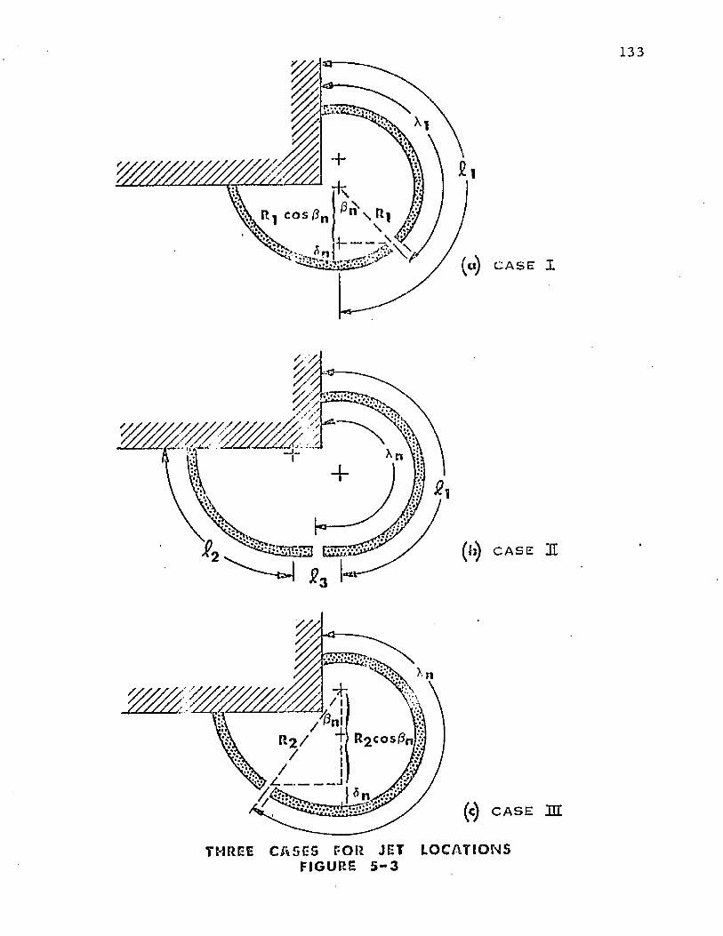
133
(tl) C A S E X
(b ) C A S E HI
Z_________ j
(c) C A S E M
THREE C A S E S F O R JET L O C A T I O N S FI GURE 5 - 3
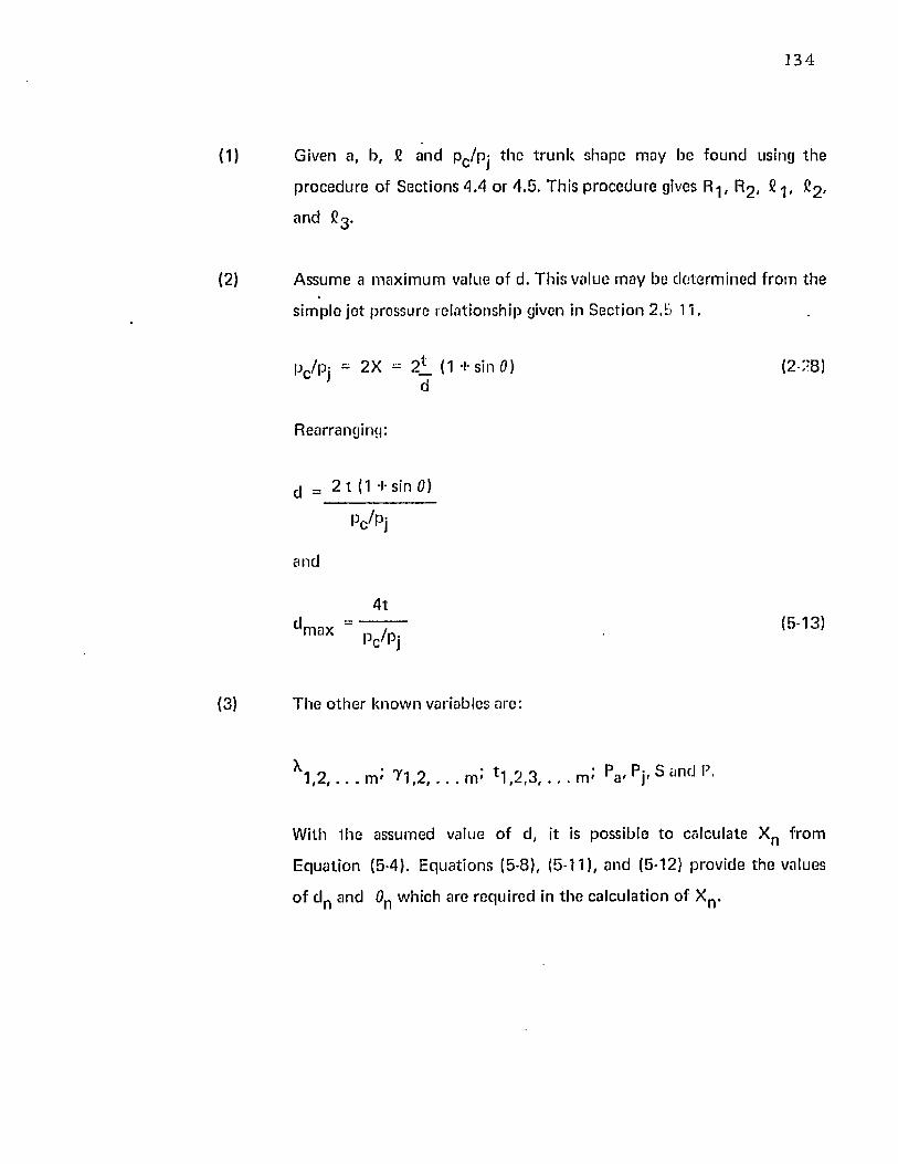
Given a, b, £ and Pc /Pj th e t ru n k shape m ay be found using th e
p rocedure of Sections A A or 4 .5 . This p rocedure gives R-|, R 2 , 2 -j, C2 ,
and £ 3 .
A ssum e a m ax im um value of d. This value m ay be de te rm ined from th e
sim ple je t pressure rela tionship given in Section 2 .5 11.
pc/pj = 2X = 2 l (1 sin 0)d
(2-28)
Rearranging;
^ = 2 t ( 1 + sin 0)
Pt/P j
and
4 td max (5-13)
T he o th e r know n variables are:
With th e assumed value o f d, it is possible to calculate Xn from
E quation (5-4). E qua tions (5-8), (5-11), and (5-12) provide the values
o f d n and 0n which are required in th e calculation o f Xn .
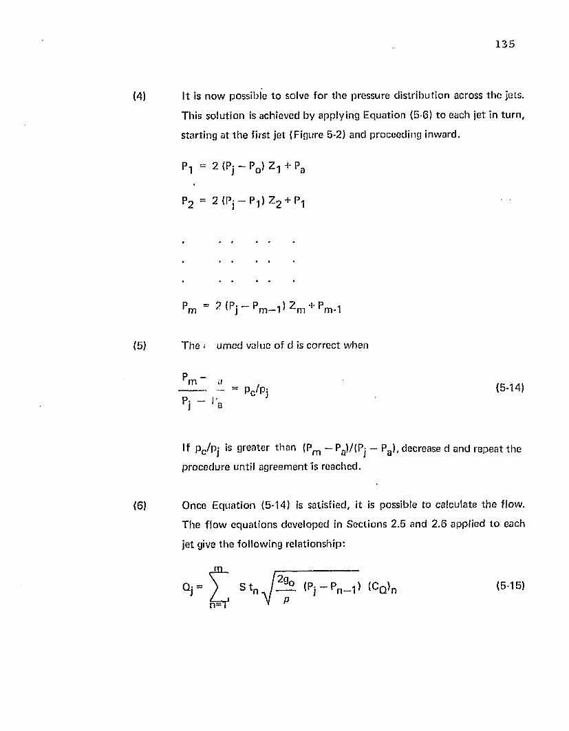
135
(4) It is n o w possib le to solve f o r t h e pressure d is t r ib u t io n across t h e jets.
T h is so lu t io n is ach ieved by a pp ly ing E q u a tio n (5-6) t o each je t in tu rn ,
s ta r t in g at t h e f irs t je t (F igure 5-2) a n d p roceed ing inw ard .
P i “ 2 (Pj - P0 ) 7.y + Pa
?2 = 2 (Pj — P 1) Z 2 + Pi
4 4
(5) T h e ; u m c d value o f d is c o rre c t w hen
p _ m a
P . — j}r j 1 a
p c /p j (5-14)
If pc /p j is g rea te r th a n (Pm - Pa)/(Pj - Pa ), decrease d and rep ea t th e
p ro c e d u re until a g re e m e n t Is reached .
(6 ) O nce E q u a t io n (5-14) is sa tisfied , it is possib le to ca lcu la te th e flow .
T h e f lo w e q u a t io n s d eve loped in S ec t io n s 2 .5 an d 2 .6 ap p lied t o each
je t give t h e fo llow ing re la t ionsh ip :
S tn ( P j - P n—,) ICQ)n (5-1E)
136
w here :
(C q ) h = 1 f o r th in je t t h e o r y
1
X. ( 1 - e “ x n) f o r e x p o n e n tia l th e o ry
5 .3 F low Restric t o r T h eo ry
5.3.1 A p p ro a c h an d A ssu m p tio n s
T h e general co n f ig u ra t io n o f d is t r ib u te d jets is sh o w n in Figure 5-1. In th e f low
re s t r ic to r th e o ry , it is a ssum ed th a t th e jets are fo rm e d b y row s of c ircu lar ho les ra lh e r th a n
by c o n t in u o u s slots. As a resu l t o f t h e spacing b e tw e en th e holes, passages for a ir f low fro m
th e cu sh io n exist. A c o n t in u o u s m o m e n tu m seal does n o t ex is t , and th e f lo w m ay ap p ro a c h
t h a t o f a p len u m ch am b er . T h e p len u m c h a m b e r a s su m p tio n s deve loped in S ec tion 2 .9 are
app licab le to th is case. T h e add it iona l a s su m p tio n s fo r th is case are as fo llow s:
5 .3 .1 .1 T h e low est p o in t o f th e t r u n k is specif ied b y (xQ, y 0 ). T h e d is tance
b e tw e en (x 0 , y 0 ) a n d th e g ro u n d is d , t h e m in im u m je t he igh t ( t ru n k
c learance) .
5 .3 .1 .2 T h e je ts on th e cu sh io n s ide o f (x 0 , y 0 ) s u p p ly ail th e f lo w in to th e
c u sh io n w hich m ain ta in s t h e he igh t d . T h e m o m e n tu m seal e f fe c t o f
th e s e je ts is neg lec ted .
5 .3 .1 .3 T h e jets on th e o u ts id e o f (x0 , y Q) a c t t o reduce th e f lo w area. A f low
c o e ff ic ien t (Cy) is used t o a c c o u n t f o r th is area red u c t io n .
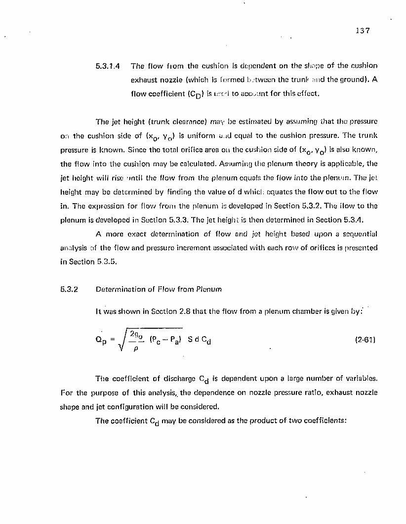
137
5 .3 .1 .4 T h e f lo w f ro m th e cu sh io n is d e p e n d e n t o n th e sh a p e o f t h e cu sh io n
e x h a u s t nozz le (w hich is fo rm e d be tw een th e t ru n k and th e g ro u n d ) . A
f lo w c o e ff ic ien t (C p ) is orr. d to a c c o u n t fo r th is e ffe c t .
T h e je t h e igh t ( t ru n k c learance) m ay be e s t im a ted by assum ing th a t th e p ressure
on t h e cu sh io n side o f (xQ, y 0 ) is u n ifo rm an d equal t o th e cush ion pressure. T h e t ru n k
p ressure is k n o w n . S ince th e to ta l orif ice area on the cush ion side o f (xQ, y Q) is also k now n ,
t h e f low in to th e cush ion m ay b e ca lcu la ted . A ssum ing th e p len u m th e o ry is app licab le , th e
je t h e igh t will rise un til th e f lo w f ro m t h e p le n u m equals th e f lo w in to th e p len u m . T h e jet
h e igh t m ay b e d e te rm in e d by f ind ing th e value o f d w hich e q u a te s t h e f lo w o u t t o t h e f lo w
in. T h e express ion fo r f low f ro m th e p len u m is deve loped in S ec tion 5 .3 .2 . T h e flow to th e
p len u m is deve loped in S ec tion 5 .3 .3 . T h e je t he igh t is th e n d e te rm in e d in S ec tion 5 .3 .4 .
A m o re e x a c t d e te rm in a t io n o f f low and je t he igh t based u p o n a sequen tia l
analysis of t h e f low and p ressure in c re m e n t assoc ia ted w ith each row o f orif ices is p resen ted
in S ec tion 5 .3 .5 .
5 .3 .2 D e te rm in a t io n o f F lo w f ro m P lenum
It w as s h o w n in S ec tion 2 .8 t h a t t h e f lo w f ro m a p len u m c h a m b e r is given by:"
q p = ( p c - p a > s d c d (2 -6D
T h e c o e ff ic ie n t o f d ischarge is d e p e n d e n t u p o n a large n u m b e r o f variables.
F o r th e p u rp o se o f th is analysis, t h e d e p e n d e n c e on nozzle p ressure ra t io , e x h a u s t nozzle
shape an d je t c o n f ig u ra t io n will be cons ide red .
T h e c o e ff ic ien t m ay b e c o n s id e red as th e p r o d u c t o f t w o coe ff ic ien ts :
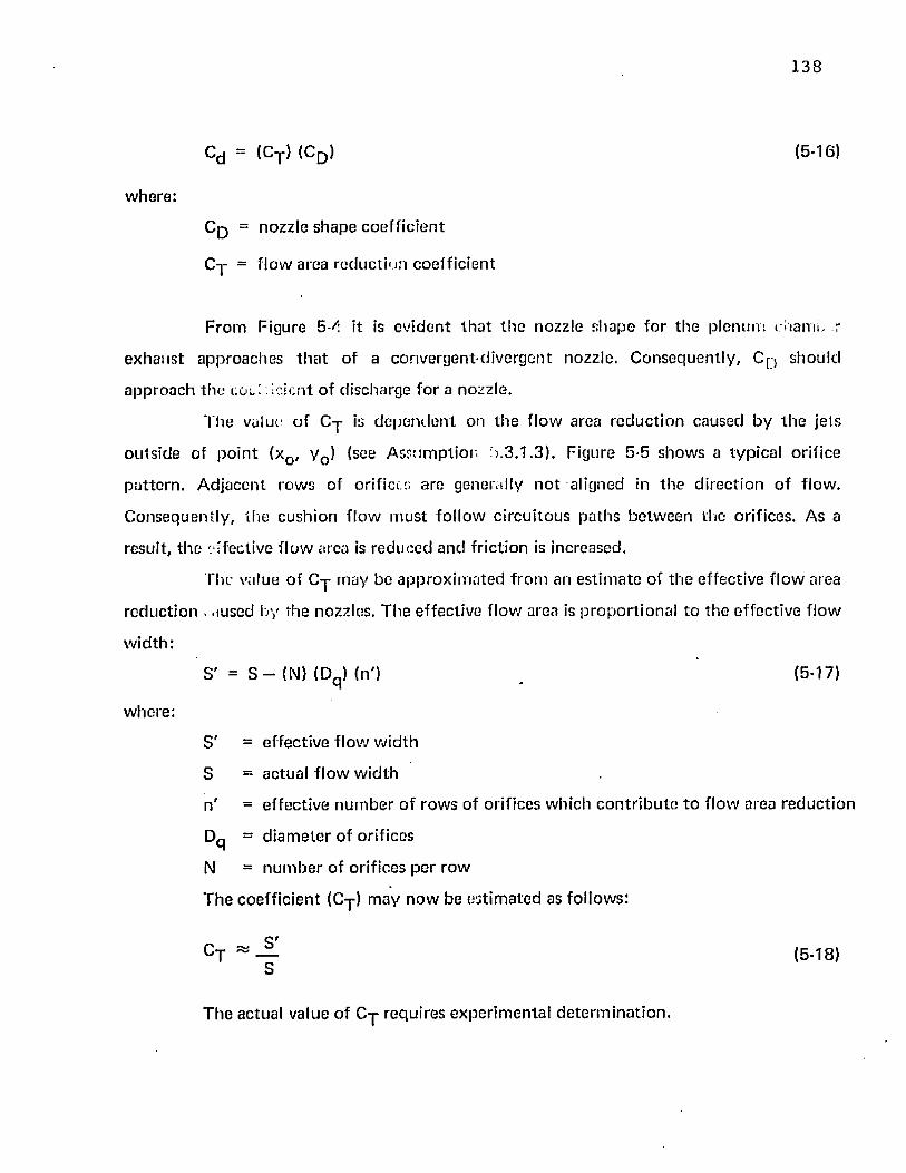
138
Cd - (Cy) (C q ) (5-16)
w here :
C q = n o zz le sh a p e c o e ff ic ie n t
C y = f lo w area re d u c t io n co e ff ic ien t
F ro m Figure 5-^: it is ev id e n t t h a t th e nozz le sh a p e fo r th e p len u m ro a n u , r
e x h a u s t ap p ro ach es t h a t o f a convergen t-d ivergen t nozzle . C o n se q u e n tly , Cp> sh o u ld
a p p ro a c h th e col! : ! c k n t o f d ischarge fo r a nozzle .
T h e value o f C y is d e p e n d e n t on th e f low area r e d u c t io n caused b y th e je ts
o u ts id e of p o in t (xQ, y 0 ) (see A ssu m p tio n 6 .3 .1 .3 ) . F igure 5-5 sh o w s a typ ica l o rif ice
p a t te rn . A d ja c en t row s o f orifice.:; a re genera lly n o t a ligned in t h e d ire c t io n o f f low .
C o n se q u e n tly , th e c ush ion f lo w m u s t fo l lo w c irc u i to u s p a th s b e tw e e n th e orif ices. As a
resu lt, t h e e f fective f lo w area is re d u c e d an d fr ic tion is increased.
The value o f C y m ay b e a p p ro x im a te d f ro m an e s t im a te o f th e effec tive f lo w area
re d u c t io n . .iused by the nozzles. T h e effec tive f lo w area is p ro p o r t io n a l to th e e ffec tive f lo w
w id th :
S ' = e ffec tive f low w id th
S = ac tua l f lo w w id th
n ' = e ffec tive n u m b e r o f ro w s o f orif ices w hich c o n t r ib u te t o f lo w area r e d u c t io n
Dq = d ia m e te r o f orif ices
N = n u m b e r o f orif ices pe r row
T h e c o e ff ic ie n t (Cy) m ay n o w be e s t im a te d as fo llow s:
S ' = S - (N) (Dq ) (n'J (5-17)
w here :
(5-18)
T h e ac tual value of C y requ ires e x p e r im e n ta l d e te rm in a t io n .
139
L O C A T I O N O F JETS RELATIVE TO L O W P O I N T
FI GURE 5 - 4
140
DIRECTION OF FLOW
TYPICAL JET SPACING
FIGURE 5 - 5
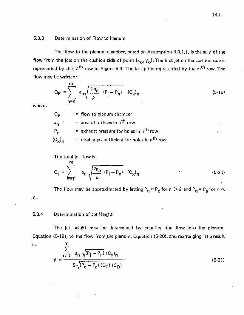
141
5 .3 .3 D e te rm in a t io n of F low to P lenum
T h e f lo w t o th e p len u m c h a m b e r , based on A ssu m p tio n 5 .3 .1 . 1 , is th e sum o f th e
f lo w f ro m th e je ts on th e cu sh io n s ide o f p o in t (xQ, y 0 ). T h e first je t o n t h e cush ion side is
rep re sen te d by th e ro w in F igure 5-4. T h e last je t is rep re sen te d b y th e m ^ 1 row . T he
f lo w m ay be w r i t te n :
m
w h ere :
Q p = I , | ’ l 1Pi _Pn> (Cx’n ( 5 ’ 1 9 )
n=£ P
Q p - f lo w to p len u m c h a m b e r
a p = a rea o f o r if ices in n * * 1 row
Pn = e x h a u s t pressure fo r ho les in n ^ row
(Cx )n = d ischarge c o e ff ic ie n t fo r ho les in n * * 1 row
T h e to ta l je t f lo w is: m
Qj - ) an J— lpj - pn> <c x>n ' I5'20)n^T1 V P
T h e f lo w m ay be a p p ro x im a te d by le t t ing Pn = Pc fo r n > £ a n d Pn = Pg fo r n ^
5 .3 .4 D e te rm in a t io n of J o t H eight
T h e je t he ig h t m ay be d e te rm in e d b y e q u a tin g th e f lo w in to th e p len u m ,
E q u a t io n (5 -19) , t o t h e f lo w f ro m t h e p len u m , E q u a t io n (5 -20), an d rearranging. T h e resu l t
is: my ____n=£ a n -^/(Pj “ pn^ ^Cx^n
d = . (5-21)
S > c - pa> <CT> <CD )
] 42
As an a p p ro x im a t io n , Pn can b e ta k e n equal t o Pc . T h e resu lt th e n becom es :
m
E q u a t io n (5-22) show s t h a t fo r th e f low re s t r ic to r th e o ry , th e je t he igh t is
d e p e n d e n t u p o n th e ra t io of£fac /pj- C o n se q u e n tly , th e p a ra m e te r pc /pj c o n t in u e s to be a
va luab le d im ens ion less q u a n t i ty fo r rela ting th e in d e p e n d e n t and d e p e n d e n t variables
a ssoc ia ted w ith th e sy s tem p e rfo rm a n c e .
5 .3 .5 D e te rm in a t io n o f Pressure D is tr ibu tion
A m o re e x a c t p red ic t io n o f f lo w a n d je t h e igh t is d e p e n d e n t u p o n a m o re e x a c t
p red ic t io n o f th e p ressure d is t r ib u t io n across th e jets. Such a p red ic t io n has been deve loped
in th is sec t io n by a sequen tia l analysis o f th e f lo w fro m each ro w o f orifices. T h e f lo w is
a ssum ed to be governed by f lo w res tr ic t io n as in t h e p len u m th e o ry .
T h e a s su m p t io n s assoc ia ted w ith t h e p len u m th e o ry (Section 2 .9 ) and th e f low
re s t r ic to r th e o ry (Section 5 .3 .1) a p p ly to th is analysis. In ad d it io n , th e fo llow ing
a ssu m p tio n s ap p ly .
5 .3 .5 . 1 F low is ad iaba tic , incom press ib le a n d fric tion less.
5 .3 .5 .2 F low f ro m th e je ts im pinges on th e g ro u n d an d is d i re c te d in all
d irec tions . T h e to ta l p ressu re o f t h e p len u m e x h a u s t is equal to th e
s ta t ic cu sh io n p ressure .
5 .3 .5 .3 T h e n e t f lo w f ro m th e cu sh io n cavity is zero.
(5-22)
143
5 .3 .5 .4 T h e to ta l pressure o f gas in t h e t r u n k a n d cu sh io n are equal to Pj and
Pc , respective ly .
T h e general a p p ro a c h t o t h e p ro b le m w as to assum e a t r u n k c lea rance (d) fo r
given values o f t r u n k p ressure (pj) and recovery pressure ra t io (pc /p j) . T h e je t he igh t fo r
each row o f th e t r u n k nozzles was d e te rm in e d f ro m th e t r u n k shape p rog ram s deve loped in
C h a p te r 4. S ta r t in g o n th e cu sh io n side o f t h e t ru n k , th e f low f rom th e m th ro w o f je ts (see
Figure 5-4) was d e te rm in e d . T h e f low o u t o f th e cush ion a t th e (m —1 ) 1,1 row o f je ts w as
a ssum ed to equal t h e f low in to th e c ush ion f ro m th e m t *1 row o f jets. S ince th e je t he igh t a t
t h e (m —I ) * * 1 row o f je ts w as k n o w n , t h e ve loc i ty and s ta t ic p ressure in th e cush ion
e x h a u s t nozz le a t t h e (m —I ) * * 1 row c o u ld be ca lcu la ted . T h e resu lting s ta t ic p ressu ie was
used t o d e te rm in e th e f low f ro m th e (m —1 J1 *1 ro w o f t r u n k orifices. T h e f lo w a n d pressure
a t su b s e q u e n t row s o f orifices w ere d e te rm in e d sequen tia l ly in a sim ilar m a n n e r until th e
p ressure a t t h e cu sh io n nozz le e x h a u s t ( the C * * 1 row o f t ru n k orifices) was fo u n d . If 1 he
c a lcu la ted a n d a ssu m ed value o f p ressure a t th e cush ion nozz le e x h a u s t d id n o t agree, th e
t r u n k c learance (d) w as a d ju s te d un til a g re e m e n t was achieved .
T h e e q u a t io n s fo r p red ic ting th e pressure d is t r ib u t io n across th e d is t r ib u te d jets
f o r t h e r e s t r ic to r t h e o r y are su m m a riz ed in t h e fo llow ing pa ragraphs.
T h e jo t ve loc ity f ro m th e nv*^ ro w o f je ts (see Figure 5-4) m ay be ca lcu la ted f ro m
B ernoull i 's e q u a t io n .
O'tlm J^ (5-231
E q u a t io n (5-23) gives t h e je t v e loc i ty fo r th e m * * 1 row o f orifices in te rm s o f t h e
k n o w n pressure d if fe re n c e across th e s e orifices. T h e ve loc ity o f t h e gas in th e t r u n k was
a ssum ed to be ze ro a n d A ssu m p tio n s 5 .3 .5 .1 a n d 5 .3 .5 .2 w ere app lied in th e d e v e lo p m e n t of
E q u a t io n (5-23).
144
T he to ta l f low from the m ^ 1 row of orifices m ay be de te rm ined by applying the
c o n tin u i ty equa tion .
( ° t ) m = ( ^ m W m ^ r J S ) (5-24)
T he en tire f low from th e m * * 1 je t is assum ed to ex h au st th rough th e p lenum
exhaust nozzle fo rm ed be tw een th e t ru n k and d ie ground. The velocity o f the gas in th e
p lenum exhaust nozzle a t a section just to th e left o f th e (m —I ) * * 1 row of jets (see Figure
5-4) m ay be c o m p u te d f rom th e c o n tin u ity equa tion . T he resulting rela tionship is:
tQt>m(v)m- i = ---------------------------- (5-25)
(d + 6 m _ 1) (S) ( c t )
E quation (5-25) predicts the velocity of th e gas in th e p lenum ex h au st nozzle a t a
section ju st t o th e Icii. o f th e (m—1 ) t *1 row of t ru n k orifices. T he values o f S and Ct are
know n and c o n s ta n t for a particu lar t ru n k design. T he value of (Q^)m was p redic ted by
E qua tion (5-24). The value o f Sm _ i m ay be de te rm ined from the t ru n k shape program
developed in Section A A. Only th e value o f d on th e right hand side o f E quation (5-25) is
unknow n . T he co rrec t value o f d is th e value which will p red ic t a tm ospheric pressure at
p lenum nozzle exhaust plane. At th is p o in t it is necessary to assume a trial value of d.
The pressure a t th e (m —1 ) ^ row of t ru n k orifices m ay be com pu ted from the
to ta l pressure and th e gas velocity. Based on A ssum ption 5 .3 .5 .2 , th e to ta l pressure a t any
po in t in th e p lenum exhaust nozzle is Pc . The resulting sta t ic pressure a t th e (m —I ) 1 *1 jet
row is
(P) = P _ (vm - 1 } 2i n m — 1 r c
2g0 (5-26)
145
E q u a t io n (5-26) p red ic ts th e s ta t ic p ressure a t th e (m —1 ro w o f t r u n k orifices.
S ince t h e s ta t ic pressure a t t h e (m —1 ) ^ row is k n o w n , ve loc ity a n d f lo w f ro m th e (rn—l ) 1-*1
ro w o f je ts m ay be ca lcu la ted . In a s im ilar m a n n e r to th e p ro c e d u re deve loped b y E q u a t io n s
(5-23) th ro u g h (5-20), th e p ressure d is t r ib u t io n fo r all t h e rem ain ing je ts m ay be c a lcu la ted
in sequence .
T h e general e q u a t io n s fo r t h e p ressu re d is t r ib u t io n ca lcu la t ion are:
f ' t ' m - n = • / — (Pj - Pm „ n ) (5-27)
( ^ m —n ~ ^ ^m—n ^ m —n ^ x ^ m —n ^ (5-28)
m —£
< Q » m -n = Y <Qt> m ~ n <5 ' 2 9 >n= o
<Q > m - n(v)m _ n = ----------------------------------- (5-30)
(d + Sm _ n ) (S) (CT )
(P)m - n _ 1 “ Pc - | V |m - .n- 2 — (5-31)2 g0
T h e pressure a t each je t m ay be ca lcu la ted in s eq u en ce until t h e m in im u m
p ressu re an d m ax im u m e x h a u s t ve loc i ty is reached . T h e m a x im u m v e loc i ty in t h e e x h a u s t
nozz le is d e te rm in e d by th e e x p a n s io n o f th e e x h a u s t f lo w f ro m th e to ta l cu sh io n p ressu re
to a tm o s p h e r ic p ressure (A ssu m p tio n s 5 .3 .5 .1 , 5 .3 .5 .2 , and 5 .3 .5 .4 ) . T h e resu lting
m a x im u m e x h a u s t ve loc ity is:
(v ) max = (CD> (S-32)
146
In Equation (5-32), th e coeffic ien t C p was in troduced t o c om pensa te fo r the
convergent-divergent shape o f th e p lenum exhaust nozzle.
T he pressure ditritaution problem m ay now be solved on an iterative basis by
varying th e je t height (d) until th e m ax im um pred ic ted p lenum exhaust velocity agrees with
th e velocity p red ic ted by E quation (5-32).
T he p rocedu re is basically th e same as ou tlined in Section 5.2.4. Total jet f low
and jet height m ay be p red ic ted from Equations (5-20) and (5-21) respectively, once the
pressure d is tr ibu tion fo r th e d is tr ibu ted jet is know n.
5.4 Analytical Results
T he d istr ibu ted jet theories require th e specification of m ore design param eters
th an th e co n c en tra te d je t theories . In particular, th e d istr ibu ted jet theories require the
specification o f th e t ru n k shape and th e nozzle size, location, spacing, and num ber. The
co n c en tra te d jet theories are useful in visualizing general trends. The d istr ibu ted je t theories
are useful in pred ic ting actual perfo rm ance of a particu lar d is tr ibu ted jet design.
4 .6 and show n in Figure 4-8. T he t ru n k material is assum ed to be inelastic. T he nozzles are
fo rm ed by 8 rows o f 5 /1 6 " d iam ete r orifices. T he spacing be tw een th e rows is 1 -1 /4" . The
t ru n k is de te rm ined by specifying X n as show n in Figure 5-2. T he values fo r Xn and the
o th e r specified variables are show n in Table 5-I.
Because of th e large n u m b er of variables involved, th e analytical results will be
p resen ted for one single design. T he design selected was th e side t ru n k discussed in Section
spacing be tw een orifices in a given row is 2 -1 /2" . T he location o f th e rows of orifices on the
T he je t he ight p red ic ted by th e d is tr ibu ted je t theo r ies m ay be com pared w ith the
c o n cen tra ted je t p red ic tions if an equivalen t je t th ickness is assum ed fo r th e d is tr ibu ted jet.
T he equivalen t jet th ickness (t) is defined as follows:
m
147
w here:
a n is t h e to ta l area pe r ro w o f jets, S is th e length o f th e je t row
( tru n k sec tion length).
Using th e above d e fin i t ion o f t , t h e ra t io d / t fo r th e d is t r ib u ted je t case becom es
equ iva len t to d / t fo r t h e c o n c e n t ra te d jet case. It m ay be n o ted th a t :
1 /X = _____? ---------t ( 1 + sin 0)
C o n sequen tly , 1 /x and d / t are equal w hen 0= 0 ° .
Figure 5-6 gives a com par ison of th e p red ic ted d / t versus Pc/P j fo r th e d is t r ib u ted
a n d c o n c e n t ra te d je t theories . Fo r th e c o n c e n t ra te d je t theo r ies , it was assum ed th a t 0 = 0 .
It is ev iden t f ro m th e figure t h a t th e je t he igh t p red ic ted b y th e f low res tr ic to r th e o ry is
cons ide rab ly low er th an th a t p red ic ted by th e various m o m e n tu m theories.
T h e re la tionsh ip be tw een C q a n d P c / P j is sh o w n in Figure 5 - 7 . T he defin i t ion o f
C q was given by E q u a tio n (3-3).
T h e p a ra m e te r C q is a f low coeff ic ien t w hich c o m p en sa te s fo r th e pressure
varia tion across th e jet. T h e physical significance o f th is pa ra m e te r was discussed in detail in
S ec tion 3.4.
In c o m p u t in g C q , all o th e r f low coeff ic ien ts w ere assum ed to be un ity . T he
resu lts sh o w n in Figure 5-7 ind ica te t h a t all d is t r ib u ted je t m o m e n tu m th eo r ies give nearly
th e sam e value o f C q . T he co rrespond ing values o f C q are slightly h igher fo r th e d is t r ib u ted
je t theo r ies th a n fo r th e B arra tt t h e o ry fo r a c o n c e n t ra te d pe riphera l je t .
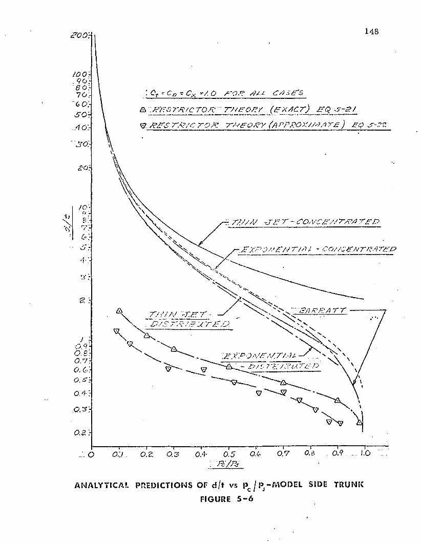
148
: cr ca - cx */. o tot /?/-;. ot.ots & ^ ' Si r x t c t o p t a / t o t y (£r* /Lc72 _ B j zE JLV P/PS TA?/C TO PI TPTO PY (a rPKOXJM a t t ) £Q
/o'-
“ 77J/A/ O'T T - 00,VC/P/V TTT T£T>
■.PXPOPPNT/AI - CO//C&NTP Arg.P
VJ PR A T Tt j o /'J yt.t :
. T X P O a / T iV T / . - H S ... - T T 7 A.'/ .:?I< TA o
0 .4 ;
0 .7o:j ore 0.3 0 .4 0.5 op: Pc / p j
ANALYTICAL PREDICTIONS OP d / t vs Pc / 1* -MODEL SIDE TRUNK
FIGURE 5 - 6
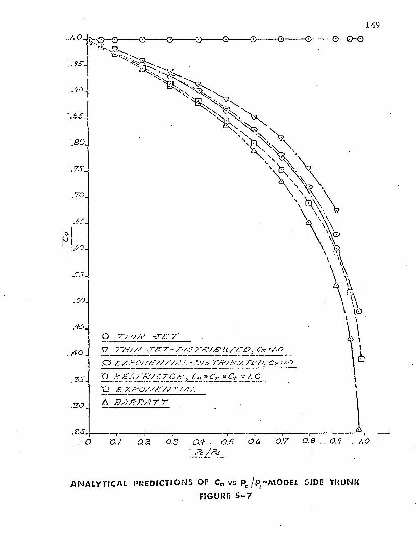
cy
O ■ T H J A ‘ - S S T
V " / / / / . / tT / z t - / 2 / s Cx *a o
o £?:*><.'v/yfAsr/s/y -y?/s 7~s?/.b\y. c*=;.oD_ K J ~ £ 7 ~ & / C 7 j O / ? > C,□ b x b o / / / j~/v r / / i j.
. 3 6 .
A B / J / ? K ’/-) T r
0 0.1 0.2 0.3 Q/h ■ 0.6 0.6 0.7 0.3. 0.9 .10~ P c / B c . . . .
A NALYTI CAL P REDI CT I ONS OF CQ vs Pc / p ^ M O D E L SIDE TRUNK
FIGURE 5 - 7
150
The d is tr ibu ted je t curves p resen ted in Figures 5-6 and 5-7 w ere based on an
assum ed t ru n k pressure of 120 psfg. C om pu ta t ions were also m ade fo r t ru n k pressures o f 80
psfg an d 1 GO psfg. The resulting values of C q and d / t were w ithin a few percen t o f those
p red ic ted a t 120 psfg. It was conc luded th a t the curves presented in Figures 5-6 and 5-7 are
de p e n d en t only on pc/pj and independen t o f the m agnitude of pj.
6. EXPERIMENTAL PROGRAM - STATIC MODEL
6.1 Experim ental A ppara tus — S ta tic Tests
Figure 6-1 shows the les t appara tus used fo r verification of the t ru n k shape, flow,
pressure d is tr ibu t ion , and jet height which w ere p red ic ted by the analysis developed in
C hapters 4 and 5. T he plexiglas side in th e tes t rig allowed th e inspection of th e
two-dim ensional shape of the t ru n k cross section. For th is reason, th e appara tus was
generally referred to as the 2D tes t rig. The to ta l tes t appara tus consisted of th ree units: an
air supply , a test section, and a t ru n k specim en.
A irflow was supplied by a Spenser Gas Booster capable o f delivering 3 ,0 0 0 c fm a t
1.65 psig. Air was duc ted to the te s t section th rough 16 feet of 12-inch d iam eter galvanized
ducting. T ru n k pressure was contro lled by adjusting a b u t te r f ly valve located in the b low er
housing ahead o f the ducting. A flow stra igh tener was positioned in the duc ting in
accordance with s tandards se t forth in Reference (47). Flow was de te rm ined by measuring
th e differential head across an orifice p late meeting ASME s p e c i f ic a t i o n s ^ ^ using a
m ic rom anom ete r w ith a 20-inch range. Air tem pera tu re upstream was m easured by a 0 -1 2 0 °
F m ercury the rm om ete r .
T he te s t section consisted of a box approx im ate ly 3 2 " wide by 4 2 " long by 5 2 "
high. T he box was cons truc ted f rom p lyw ood and plexiglas. The f ro n t of the box was open
to allow air to exhaust and the f lo o r was movable to enable the model to s im ulate varying
vehicle heights. S ixteen sta t ic pressure taps, spaced tw o inches apart, were installed along
th e centerline of th e tes t section floor.
T he t ru n k specim en u n d e r tes t was m ade of a ny lon-hypalon material which was
fastened in the te s t section by w ooden stringers. Six static pressure taps spaced 2-1/2 inches
a p a r t were installed along th e centerline o f the t ru n k in the je t region. T he t runk section was
151
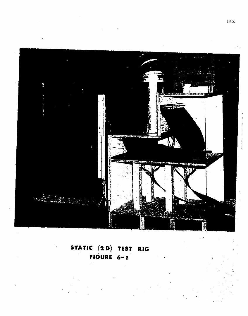
152
STATIC ( 2 D ) TEST RIG
FIGURE 6 - 1
153
3 2 " w ide a n d 5 7 " long. A f lap was insta lled o n th e edge o f th e t r u n k to seal leakage
b e tw e en Ihe t r u n k an d th e t e s t se c t io n edges. Details of th e je t c o n f ig u ra t io n a n d th e t ru n k
e lastic p ro p e r t ie s are given in A p p e n d ix IV. T h e t r u n k d im e n s io n s w e re th e sa m e as th o se
listed in T ab le 5-1. C o n s e q u e n t ly , th e t ru n k te s t spec im en rep resen ted th e side t ru n k w hose
sh a p e w as an a ly zed in C h a p te r 4 an d w hose f low , p ressure d is t r ib u t io n , and j e t he igh t was
ana ly z e d in C h a p te r 5. 1
A irf lo w w as d u c te d in to t h e t r u n k th ro u g h th e t o p o f th e te s t sec t io n . T h e air
f low ed th ro u g h th e t r u n k , o u t of th e jets, and e x h a u s te d th ro u g h th e f ro n t o f th e te s t
sec t ion . T h e f low caused a s ta t ic p ressu re t o bu ild u p b e tw e en th e t r u n k and th e rear o f th e
b o x w h en th e f lo o r w as in place. T h is pressure w as eq u iv a len t t o th e cush ion pressure (pc ).
B o th cu sh io n p ressu re (pc ) a n d t ru n k p ressure (p;) w ere m easu red by p ressure ta p s installed
in t h e t o p a n d rea r o f t h e te s t sec t io n . All p ressure ta p s w ere c o n n e c te d t o a 100 -tube well
ty p e m a n o m e te r b ank . W ater was used as th e m a n o m e te r f lu id .
A grid w as m ark e d on th e plexiglas side o f th e te s t sec t ion to fac ili ta te
o b se rv a t io n a n d m e a s u re m e n t o f th e t ru n k shape. T ru n k shape a n d low p o in ts were
m ea su red w ith a scale.
6 .2 E x p e r im en ta l P ro c ed u re s ~ S ta t ic Test
It w as necessary to d e te rm in e th e m a g n i tu d e o f leakage f low an d th e co e ff ic ien t
o f d ischarge fo r th e je ts p r io r to c o n d u c t in g th e f lo w verif ica tion tes ts . T h e leakage f low was
m ea su red b y installing in th e te s t sec t ion a t r u n k spec im en w i th o u t je ts a n d m easuring th e
f lo w f o r va rious values o f pj b u t w ith pc = 0. T h e resu lts o f t h e leakage f lo w te s t are
s u m m a riz e d in A p p e n d ix V. T h e f lo w c o e ff ic ie n t f o r th e je ts was m easu red b y repea ting th e
leakage f low p ro c e d u re a f te r th e je ts had been insta lled in th e t r u n k spec im en . T h e results of
t h e c o e ff ic ie n t o f d ischarge te s t a re su m m arized in A p p e n d ix VI.
In order to verify the predictions of trunk shape, jet height (d) and pressure
coefficient (Cq), tests were conducted on a trunk specimen of the configuration specified in
154
T able 5-1. This con figu ra t ion was identical to th e side t ru n k shape ana lyzed in C hap te r 4 and
C hap te r 5.
T he in d ep e n d e n t variables in th e tes ts w ere t ru n k pressure (pj) and vehicle he ight
(H). T h e vehicle he igh t was set a t 10 pos it ions in 1-inch inc rem en ts be tw een 4 .5 and 13.5
inches. F o r each vehicle he ight, th e t ru n k p ressure was set a t nom inal pressures o f 4 0 , 60 ,
80 , 100, 120 , an d 140 psfg. A to le rance o f ± 2 psf was a llow ed in th e p ressure se tt ing . A t
t h e beginning o f each run , th e a m b ie n t pressure and te m p e ra tu re w ere reco rded . T he
m ic ro m a n o m e te r w hich m easured th e d ifferen tia l p ressure across th e ASME f low orifice was
leveled and zeroed . T h e vehicle h e igh t was se t by adjusting th e su p p o r ts fo r th e m ovable
f loor. T he desired t ru n k pressure was o b ta in e d by ad justing th e b u t te r f ly valve in th e b low er
housing.
T he follow ing da ta was co llec ted and reco rded .
(1) T h e loca tion o f th e low p o in t on th e t ru n k was de te rm in e d by visual
s ighting and its c o o rd in a te s w ere m easured f ro m a c o o rd in a te sys tem
grid w ith a steel rule.
(2) T h e je t he igh t was m easu red b y m eans of ca lib ra ted steel rods; th e rod
was p laced on th e f lo o r o f th e m odel so th a t its longitudinal axis was
parallel to th e d irec tio n o f f low from u n d e r th e t ru n k . T he rod was
th e n slid u n d e r th e t ru n k until it was p os it ioned below th e low p o in t of
t h e t ru n k . Clearance, o r th e I r ' k of it, b e tw een the rod and th e t ru n k
was visually d e te c te d and a larger, o r smaller, rod was te s ted fo r
e q ua li ty o f rod d iam e te r and je t he ight. T he rods w ere ca lib ra ted to
0 .001 inch in inc rem en ts of a p p ro x im a te ly 0 .0 1 ' inch be tw een 0 .03 and
1 . 0 0 inch.
155
(3) T h e p ressu re d is t r ib u t io n s o n th e f loo r an d t ru n k w ere ind ica ted on th e
m ic ro m a n o m e te r bank , as w ere t h e cush ion and t ru n k region pressures.
(4) T h e m ic ro m a n o m e te r , th e r m o m e te r , and u p s tream pressure readings
w ere reco rded .
P h o to g ra p h s of th e t ru n k shape w ere m ade f o r a run w ith Pj = BO an d th e vehicle
he igh t varied in 1.0 inch in c re m e n ts b e tw e en 13 .5 and 4 .5 inches.
T h e resu lts o f th e te s ts are s u m m a riz e d in S e c t io n 6 .3 . T h e variables used in th is
c h a p te r are su m m a riz ed in C h a p te r 5.
6 .3 S u m m a ry o f Results — S ta tic Tests
6.3.1 In tro d u c t io n
E x p e r im e n ts w ere c o n d u c te d on a t r u n k spec im en w hich s im u la ted th e side t r u n k
c o n f ig u ra t io n s h o w n in Figure 4-9. Th is co n f ig u ra t io n w as sim ilar to th e side t ru n k o f th e
m odel sh o w n in F igure 4 -8 w hose sh a p e was ana lyzed in C h a p te r 4. T h e verif ica tion of th e
t r u n k shape p red ic t io n s are p resen ted in S ec t io n 6 .3 .2 .
T h e side t r u n k specim en w as also sim ilar t o t h e m odel ana lyzed f o r je t he ight,
p ressure d is t r ib u t io n and f low in C h a p te r 5. T h e de ta ils fo r th is co n f ig u ra t io n w ere
s u m m a r iz e d in T ab le 5-1. T h e ve rif ica tions o f th e t ru n k f low ch arac te r is t ic s a re p re se n ted in
S ec t io n 6 .3 .3 .
6 .3 .2 T r u n k S h a p e
T h e p red ic te d a n d ex p e r im e n ta l values o f 2 x Q and y Q fo r th e f ree t r u n k shape
are s h o w n in Figures 6-2, 6-3, and 6-4 respectively .
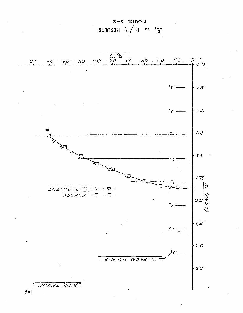
Z - 9 aunou snnsmi rt i /°<i SA
o._8 ‘0 £'Q V O6 0
KbX&MJ. . -!
£V&* c7'£? M O X J .
- & E ‘
" M v n & j . z a t s ' Z9 S I
'2T
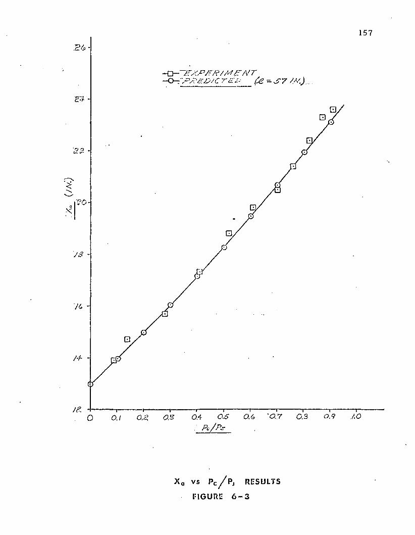
157
rxpfR/M£’/\f r
J 3
AO0.6 ' 0.7 0 .30.40 0.1P c / P r
x 0 v s P c / P j RESULTS
FIGURE 6 - 3
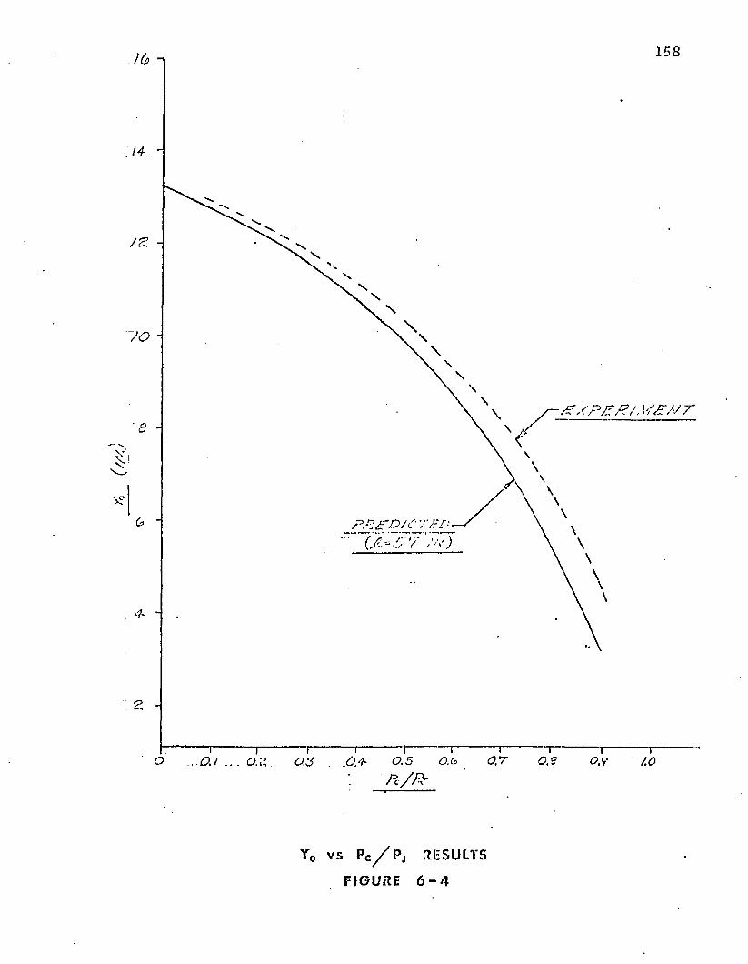
158
. n - r -' (jL~5'7"'<va)
0 .9O 0.1 AOP c /R r
Y0 v s PC// P j RESULT5
FIGURE 6 - 4
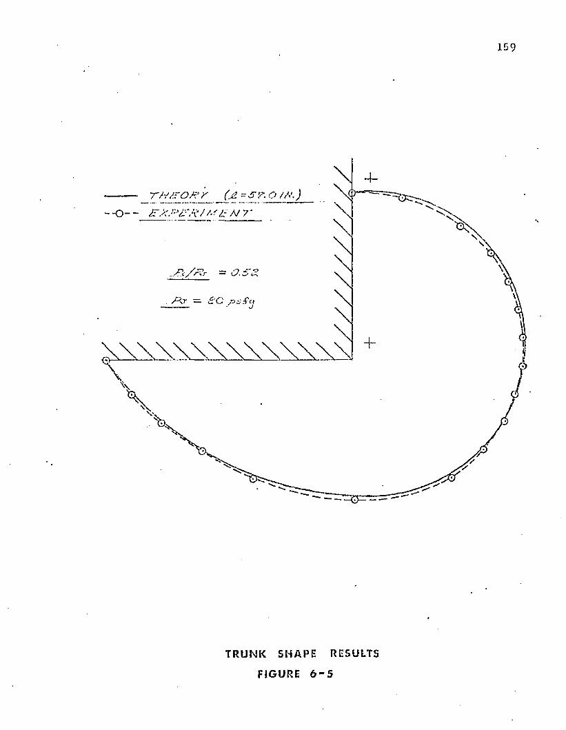
159
'TH/TO# r (jZ~& f”. O /A'.)
- o - - z-Vw',;v:-'/Vj / /• ''/ .- n y
\
T RUNK SHAPE RESULTS
FIGURE 6 - 5
260
T h e t r u n k segm en t length ( J2 ^) is defined as th e length o f th e t ru n k segm en t
b e tw een th e a t ta c h m e n t p o in t (a, b) and th e low p o in t (xQ, y 0 ). Th is segm en t is i llustra ted
in Figure 5-4. T h e length o f J2 -| is im p o r ta n t in de te rm in ing th e loca tion of th e orifices
relative t o th e low p o in t (xQ, y Q). T h e d is tance f ro m th e a t ta c h m e n t p o in t (a, b) to th e n * * 1
row o f orifices is de fined by X n . For an inelastic t ru n k , th e value o f X n is in d ep e n d e n t of
pc /p j w hile tho value of 1! -j is n o t . T he values o f th e X n 's and are p lo t te d versus pc /Pj in
F igure 6-2. A value of X n g rea ter th a n £-) ind ica tes t h a t th e n * * 1 row of orifices is on the
cush ion side of the low p o in t (xQ, y 0 ). F igure 6-2 show s th a t th e n u m b e r of row s of orifices
on th e cush ion side of t h e low p o in t varies from 3 a t Pc/p j = 1.0 to 6 a t pc /p j = 0 .9 . Close
ag reem en t be tw een th e o ry an d ex p e r im e n t is show n by th e curve.
Figure 6-3 show s th e varia tion o f th e ho r izon ta l pos it ion of the t ru n k low p o in t
(XQ) w ith p c/pj. It is ev iden t f ro m th e curve th a t th e ag reem en t be tw een th e o ry and
e x p e r im e n t is excellen t.
Figure 6-4 show s th e varia tion o f th e vertical pos it ion of th e t ru n k low p o in t (Y 0 )
w ith pc/p j. I t is ev iden t from th e curve t h a t the ag reem en t decreases as p c /pj increases. T h e
slight d iffe rence be tw een p red ic ted and m easu red values o f Y 0 was p ro b ab ly d u e to a
vacuum p ro d u c e d just to t h e a tm o sp h e r ic side of t h e t ru n k low po in t . This p h e n o m e n a
w ou ld te n d to fo rce th e t ru n k d o w n . T h e p h e n o m e n a is discussed in m ore detail in S ec tion
6 .3 .2 .
Figure 6-5 show s a com parison of th e p red ic ted and m easured t ru n k shape fo r
pc /p j = 0 .5 . It is ev iden t t h a t th e ag reem en t be tw een th e o ry and e x p e r im e n t fo r th e free
t r u n k shape is excellen t.
In o rder to d e te rm in e th e va lid ity o f th e g round loaded t ru n k shape p red ic tion , a
second series of te s ts was c o n d u c te d . In th is series of tes ts , th e cush ion area was ven ted to
th e a tm osphe re . T h e t ru n k c learance (YQ) was varied and th e resulting f o o tp r in t length £ 3
was m easu red w ith a scale. T h e resulting values o f C ^ versus Y n /Y are c o m p a re d w ith th e° U OO
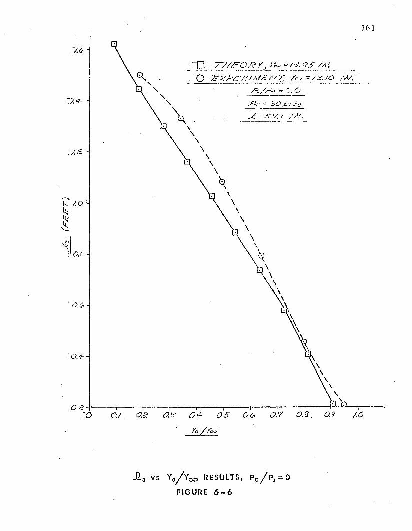
(ra
ar
)
161
' X 3 . . . 7~/i'£'o j? y J >j-~ -■=&a s / m ..:Q F x a a x / A/a’A/r, >' = / : s.jo / v ;
:r . ^ , Q
y7?/' - SO/^.'■-S’j
=■ 'r Z / //V.
7 0 -
: g so j o.a a ' s o.4- o.s < 2 6 os? o.s 0.9 AO:o
Ya / / o o
-6-3 v s Y o ^Y o a RESULTS, Pc / P j = 0
FIGURE 6 - 6
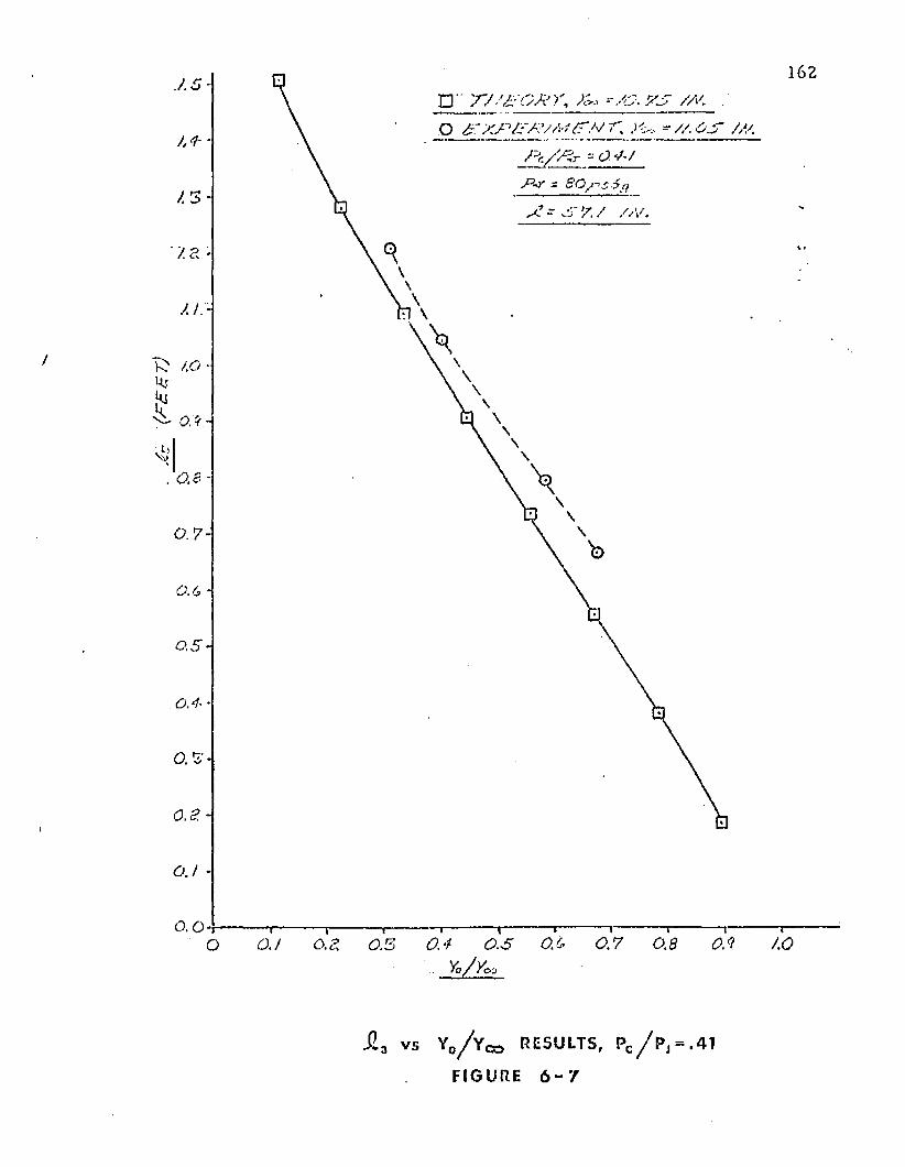
(Ftt
T)
Q " T / W G X A
o . * /
J2a v s Y0/ Y co RESULTS, Pc / P j = .41
FIGURE 6 “ 7
163
ana ly t ica lly p red ic te d values in Figure 6 -6 . T h e f igure sh o w s th a t t h e ag reem en t b e tw e en
t h e o r y and e x p e r im e n t is good fo r p c/p j = 0 .
A se co n d run was m ad e w ith Pc/Pj = 0 .4 1 . During th is run, t h e cush ion pressure
was m a in ta in e d b y in t ro d u c in g f lo w in to th e cu sh io n area f ro m a s e p a ra te air so u rce and
ven ting th e resu lting cush ion f lo w th ro u g h th e f lo o r o f t h e te s t sec t ion . T h e resu lting values
o f £ 3 versus Yg/Yoo are c o m p a re d w ith th e ana ly tica lly p red ic ted values in Figure 6-7. T he
f igure sh o w s good a g re e m e n t be tw e en th e o ry and e x p e r im e n t .
T h e t ru n k sh a p e e x p e r im e n ts have d e m o n s t ra te d th e accu racy o f t h e analytical
m odels deve loped in C h a p te r 4 fo r p red ic ting th e t r u n k low p o in t , th e loca t ion o f th e
nozzles , t ru n k shape, t h e cross-sectional area , and th e f o o tp r in t length.
6 .3 .2 F low C haracte ris tics
T h e results o f t h e tes ts f o r leakage f lo w are sh o w n in A p p e n d ix V. T he
e x p e r im e n ta l ly d e te rm in e d f lo w c o e ff ic ien t f o r t h e t r u n k orif ices (C ^ ) is given in A p p e n d ix
VI.
T h e in fluence o f vehicle (floor) he igh t (H) on Pc /Pj is sh o w n in T ab le 6 -I. This
t a b le sh o w s t h a t th e p ressu re ra t io (pc/p j) is largely in d e p e n d e n t o f th e t r u n k pressure (pj).
T h e in fluence o f vehicle he ig h t (H) on th e je t he igh t- th ickness ra t io (d /t) is sh o w n
in T ab le 6 -II. T h e resu lts s h o w t h a t th e je t he igh t- th ickness ra t io (d /t ) is n o t s trong ly
d e p e n d e n t on t ru n k pressure (pj).
T h e in fluence o f vehicle h e ig h t (H) on th e p ressu re c o e ff ic ien t (Cq ) is sh o w n in
T a b le 6 -III. T h e resu lts s h o w t h a t Cq is largely in d e p e n d e n t o f t r u n k p ressure {pj). T he
m e th o d b y w h ich Cq was c a lcu la ted is given in A p p e n d ix VII. Since t h e je t he igh t (d) and
p ressure co e ff ic ien t (Cq) are largely in d e p e n d e n t of pj, t h e p re se n ta t io n o f ex p e r im en ta l
resu lts can be g rea tly s im plif ied . T ab le 6 -IV show s th e average values o f th e d a ta c o llec ted a t
th e various f lo o r heights . These values a re assum ed t o be in d e p e n d e n t o f pj.
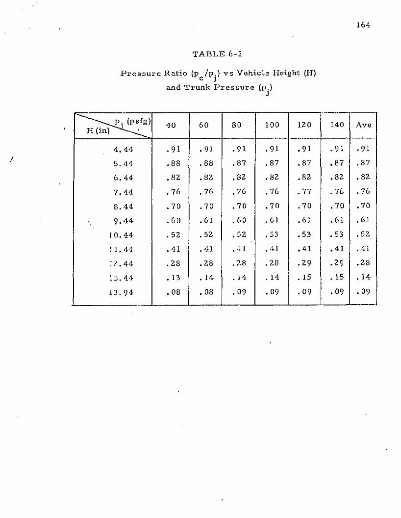
164
T A B L E 6-1
P r e s s u r e K a t i o (p / p . ) v s V e h i c l e H e i g h t (H)c J
an d T r u n k P r e s s u r e (p.)
( p s f g ) H ( i n p ^ ^
4 0 60 8 0 100 120 140 A v e
4 . 4 4 . 9 1 . 9 1 . 9 1 . 9 1 . 9 1 . 9 1 , 9 1
5. 4 4 . 8 8 , 8 8 . 8 7 . 8 7 . 8 7 . 8 7 . 8 7
6 . 4 4 . 8 2 . 8 2 . 8 2 . 8 2 . 8 2 . 8 2 . 8 2
7 . 4 4 . 7 6 . 76 . 7 6 . 7 6 . 77 . 76 . 76
8 . 4 4 . 70 . 7 0 . 7 0 . 7 0 . 7 0 . 7 0 . 7 0
\ 9 . 4 4 . 6 0 . 6 1 . 6 0 . 61 . 61 . 61 . 61
1 0 . 4 4 . 52 . 5 2 . 52 . 5 3 . 5 3 . 53 . 52
1 ] . 4 4 . 41 . 4 1 . 4 1 . 41 . 4 1 . 4 1 . 4 1
J'/. 4 4 . 28 . 2 8 . 2 8 . 28 . 2 9 . 2 9 . 2 8
13. 4 4 . 13 . 14 . 14 . 14 . 15 . 15 . 14
13 . 9 4 . 08 . 08 . 0 9 . 0 9 . 0 9 . 0 9 . 0 9
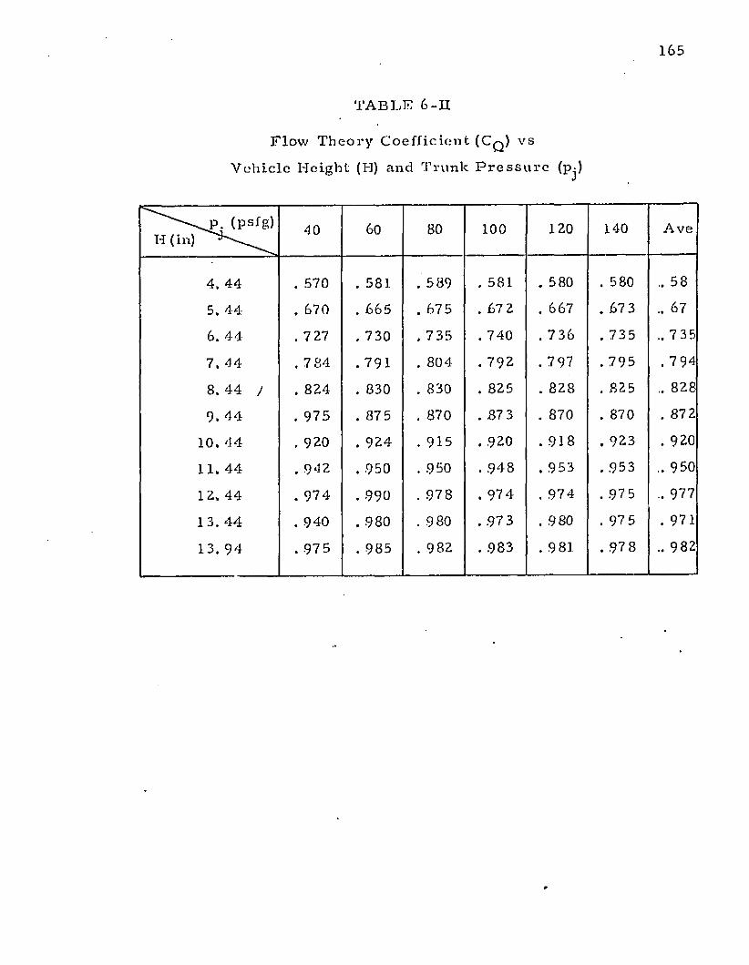
165
TA BL E 6 -II
F l o w T h e o r y C o e f f i c i e n t ( C q ) v s
V e h i c l e H e i g h t (H) and T r u n k P r e s s u r e (p.)J
(psfg)H (in)
40 60 80 100 120 140 A v e
4. 4 4 . 570 . 581 . 5 8 9 . 581 . 580 . 580 .. 58
5. 4 4 . 670 . 6 6 5 . 675 . 67 2 . 667 . 67 3 .. 67
6. 4 4 . 727 . 730 . 7 3 5 . 740 . 7 3 6 . 7 3 5 . .7 35
7. 4 4 . 7 84 . 7 9 1 . 8 0 4 . 7 9 2 . 797 . 7 9 5 . 7 94
8. 4 4 J . 82 4 . 830 . 830 . 825 . 8 2 8 . 825 .. 828
9* 4 4 . 9 7 5 . 875 . 870 . 87 3 . 870 . 870 . 872
10. 4 4 . 920 . 9 2 4 . 915 . 920 . 9 1 8 . 92 3 . 920
11. 4 4 . 9 4 2 . 950 . 950 . 9 4 8 . 9 5 3 . 9 5 3 .. 950
i—> ro < . 9 7 4 . 990 . 9 7 8 . 9 7 4 . 97 4 . 97 5 .. 977
13. 4 4 . 940 . 980 . 980 . 97 3 . 980 . 97 5 . 971
13. 9 4 . 97 5 . 98 5 . 9 82 . 9 83 . 981 . 97 8 .. 982
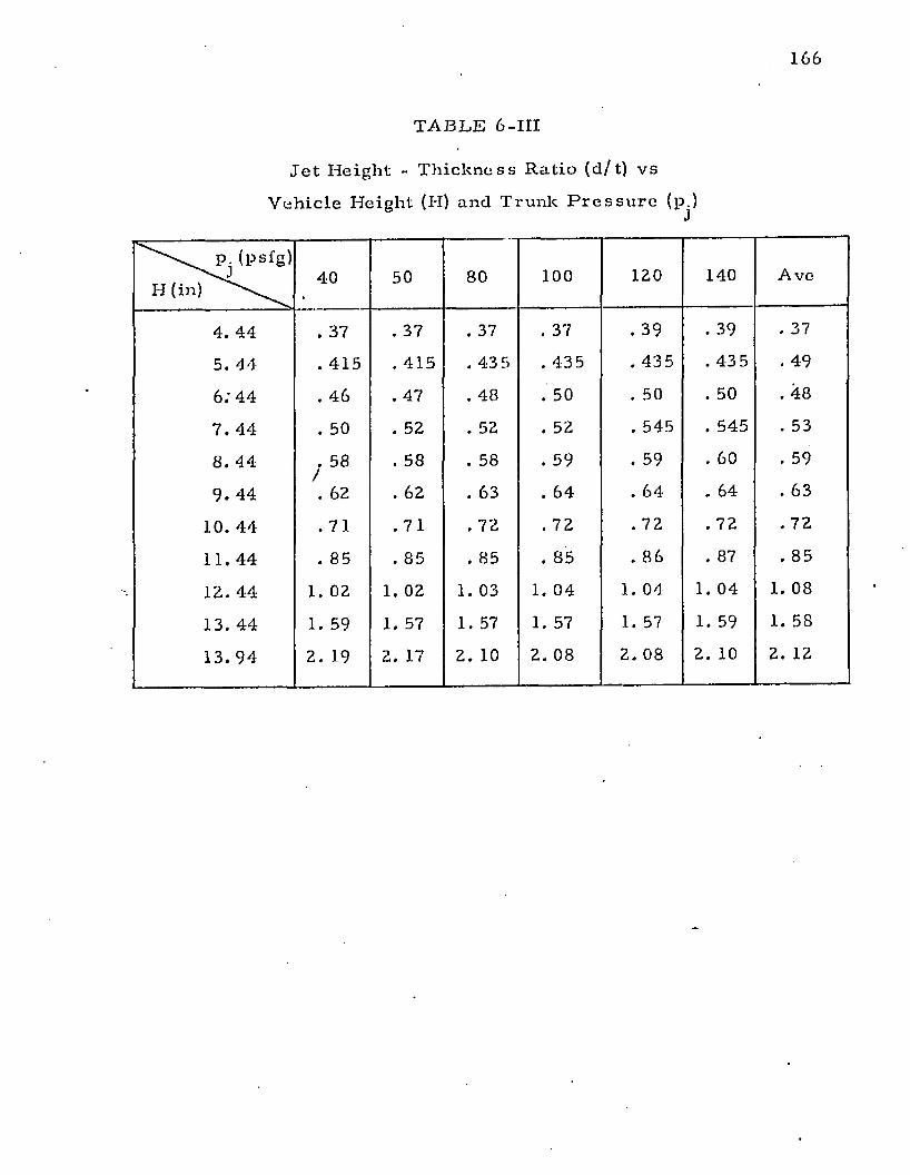
1 66
TA B L E 6-III
J e t H e i g h t - T h i c k n e s s R a t i o ( d / t ) v s
V e h i c l e H e i g h t (H) a n d T r u n k P r e s s u r e (p.)J
( p s f g )
H40 50 80 100 120 140 A v e
4. 44 . 37 . 37 . 37 . 37 . 39 . 39 . 37
5. 4 4 . 4 1 5 . 4 1 5 . 4 3 5 . 43 5 . 43 5 . 43 5 . 49
6; 4 4 . 4 6 . 47 . 48 . 50 . 50 . 50 . 48
7 . 44 . 50 . 52 . 52 . 52 . 545 . 545 . 53
8 . 4 4 . 58 /
. 58 . 58 . 59 . 59 . 60 . 59
9 . 4 4 . 62 . 62 . 63 . 6 4 . 6 4 . 64 . 63
10. 4 4 . 7 1 . 7 1 . 72 . 72 . 72 . 72 . 72
11. 4 4 . 85 . 85 . 85 . 85 . 8 6 . 87 . 85
12. 44 1. 02 1. 02 1. 03 1. 04 1. 04 1. 0 4 1. 08
13. 4 4 1. 59 1. 57 1. 57 1. 57 1. 57 1. 59 1. 58
13. 9 4 2. 19 2. 17 2 . 10 2. 08 2. 08 2. 10 2. 12
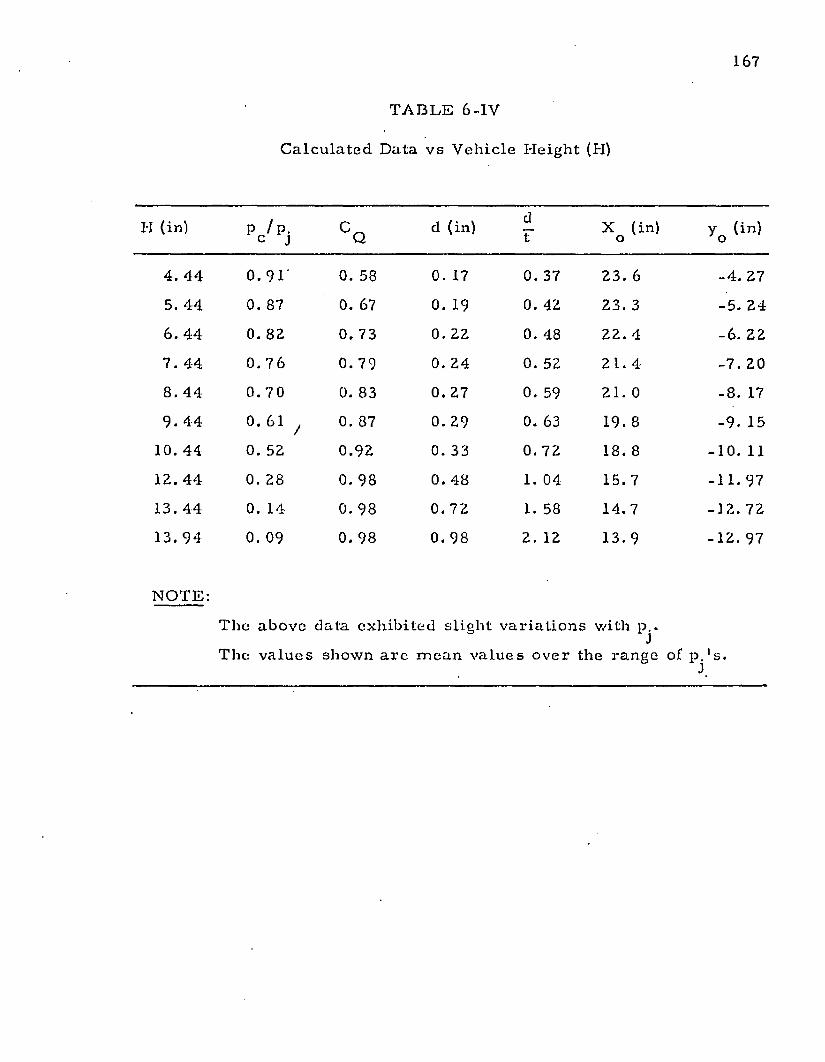
167
N O T E :
T A B L E 6 -IV
C a l c u l a t e d Da t a v s V e h i c l e H e i g h t (H)
II (in) p c /Pj C Qd (in)
dF
X (in) o y o (in)
4. 4 4 0. 9 1 ‘ 0. 58 0. 17 0. 37 23 . 6 - 4 . 27
5. 44 0. 87 0. 67 0. 19 0. 42 23. 3 - 5 . 2 4
6. 4 4 0. 82 0. 73 0. 22 0. 48 22 . 4 - 6 . 22
7 . 44 0. 7 6 0. 79 0. 2 4 0. 52 21 . 4 - 7 . 20
8. 4 4 0. 7 0 0. 83 0. 27 0. 59 21. 0 - 8 . 17
9. 4 4 0. 61 / 0. 87 0. 29 0. 63 19. 8 - 9 . 15
10. 44 0. 52 0 . 9 2 0. 33 0. 72 18. 8 - 1 0 . 11
12. 4 4 0. 28 0. 98 0. 48 1. 04 1 5 . 7 - 1 1 . 97
13. 44 0. 14 0. 98 0. 72 1. 58 1 4 . 7 - 1 2 . 72
13. 9 4 0. 09 0. 98 0. 98 2. 12 13. 9 - 1 2 . 9 7
T h e a b o v e dat a e x h i b i t e d s l i g h t v a r i a t i o n s w i t h p .
T h e v a l u e s s h o w n a r e m e a n v a l u e s o v e r the r a n g e of p . ' s .
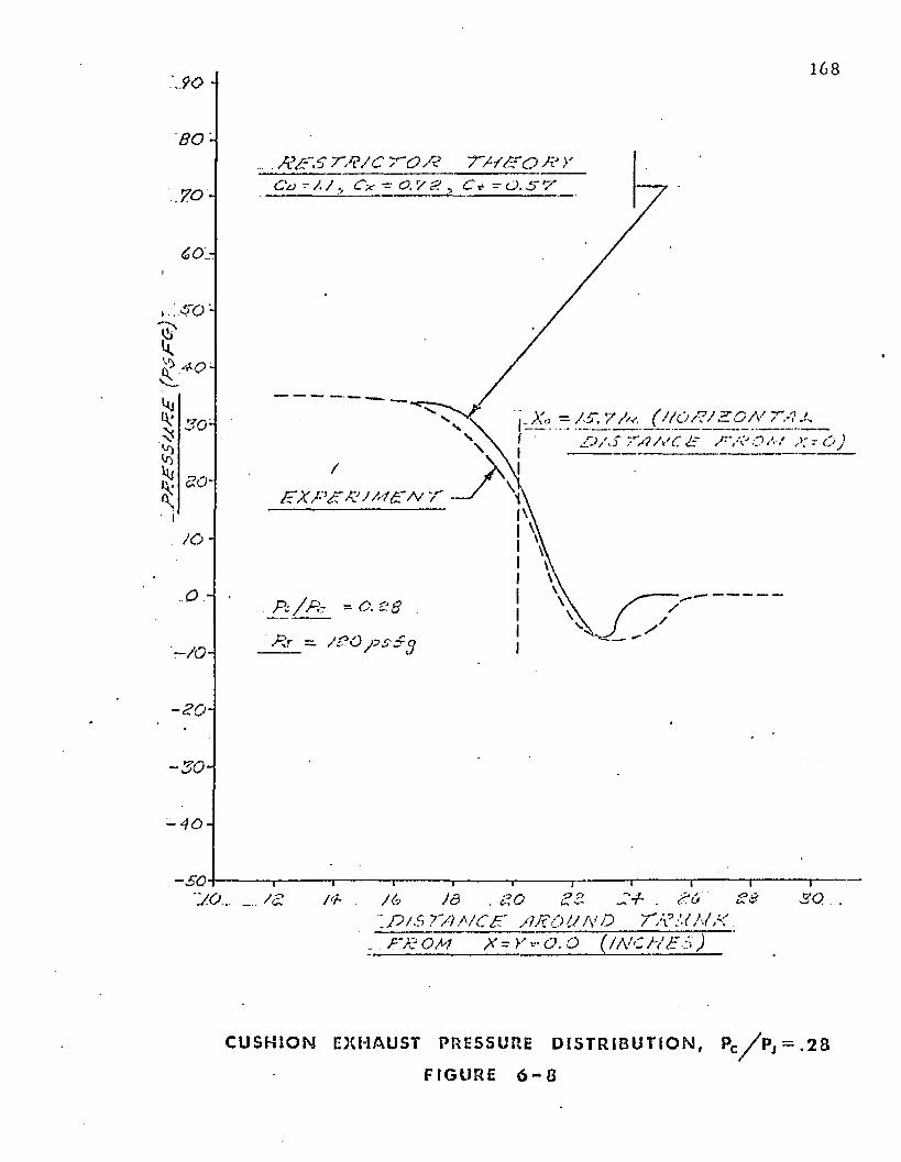
PJ?£
SSU
P£
(PSP
Cr)
7
168
8 0. . . . P p ' O P P / C P O P T / / / C O P >
C x ~ 0 . ' / g > C f ^ O . S P
- /S. ' /P. ( / /O P/P DA' i CJ/S C/i/SC C P P o ,
P X P P P J P P P VJ
/o-
- 3 0 -
- 4 0 -
- s o8 8 S + . 8 6 8 0/ 6
i f / / 6 TO A/C E AR O UN D T P P N K _ PX: CM X - Y --- O. O ( INC H £ 3 )
C U S H I O N EXHAUST PRESSURE D I S T R I B U T I O N , PC // p j = . 2 8
F I GU RE 6 - 8
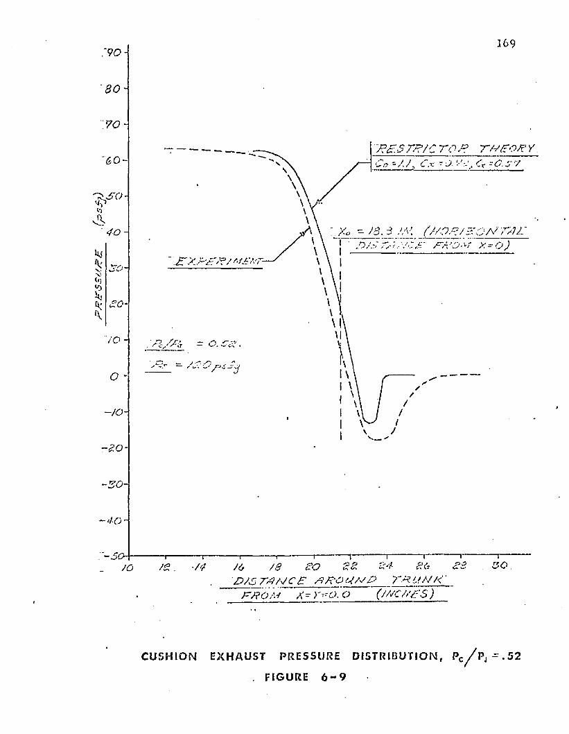
169
y?£S r/?/c t o /? T/y/ro/e y
40 -T A X - O )
~ x r x x - x ' j? /
JO -
-to-
£o/ $D J S T A M C e X X ' O U ^ f j T K l i M K '
TKOM X- Y-tO, O (/X’C/>'/:$_)___
C U S H I O N EXHAUST PRESSURE DI ST RI BUT I ON, PC// p j ^ . 5 2
FIGURE 6 - 9
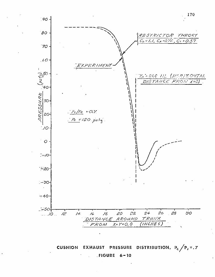
9 0 -170
80 -
70
CO
A"40-
0V
<T
30-
80-
J O -
O -
~ -}0 -
'~ a o -
-30-
j ?£: s t p / c ro J ? r:. c» O r - - a n:~c* =0.57
J Y X P P P J M tP J T
f, x?/. c j ,v. (V/r:-.?/.? o j t / kl d/s'm /S c/t" pvi;o?~ / a‘=o) .
r 4 0 -
‘- '5 0 - - 1—8c>
1----------- 1----------- 1-----------1----------- 1------- — i iJO.. SP /4 /t. 36 .SO 88 8P
' . D / 0 7 /1 . y e p P P O t t M O 7 ' P i O ' J X • P P O M X - Y - O. 0 ( / P C / / 8 S )
83 s o
C U S H I O N EXHAUST PRESSURE DISTRI BUTI ON, PC / / p j = . 7
FIGURE 6 - 1 0
171
E x p e r im en ta l ly m easu red s ta t ic p ressure d is t r ib u t io n s a long th e cu sh io n e x h a u s t
nozz le a t th e t r u n k su rface for t h e 120 psfg t ru n k p ressure run are sh o w n in Figures 6 -8 ,
6-9, an d 0 -10 . T hese f igures s h o w th e pressure d is t r ib u t io n s fo r p ressure ra t io s (pc /p j) of
0 .2 8 , 0 .5 , a n d 0 .7 2 respective ly .
V alues o f d / t a n d C q ca lcu la ted f r o m ex p e r im en ta l m ea su rem e n ts in th e pj = 120
psfg ru n are sh o w n in Figures 6-11 an d 6-12 respectively .
It w as fo u n d t h a t t h e value o f C q p red ic te d by th e d is t r ib u te d je t m o m e n tu m
th eo r ies was in reasonab le a g re e m e n t w ith th e ex p e r im en ta l results . How ever, th e je t he igh t
p red ic te d by th e m o m e n tu m th e o r ie s was an o rd e r o f m a g n i tu d e h igher th a n th a t observed .
T h e f lo w re s t r ic to r th e o ry was fo u n d to give m uch b e t t e r a g re e m e n t w ith
e x p e r im e n ta l results . In app ly ing th e f low res tr ic to r t h e o r y to th e ex p e r im en ta l m odel, it
w as necessary t o se lec t values fo r th e th re e f low coeff ic ien ts . These co eff ic ien ts are C ^ , C q ,
a n d C-p
T h e c o e ff ic ie n t is th e t ru n k orifice coe ff ic ien t . T h e m e a su rem e n t of th is
c o e ff ic ien t is d iscussed in A p p e n d ix VI. T h e values o f C ^ versus the pressure ra t io across th e
t ru n k (Px /Pj) a re s h o w n in Figure V I 1 - 1 (append ix ) . W hen cush ion pressure is p resen t , th e
value o f Px /Pj varies a ro u n d th e t ru n k . How ever, s ince th is va ria tion is n o t large, a c o n s ta n t
value of C ^ / = 0 .7 2 was assum ed .
T h e c o e ff ic ie n t C q is in te n d e d to eva lua te th e eff ic iency o f th e
conve rgen t-d ivergen t n o zz le fo rm e d b e tw e e n th e t ru n k a n d th e g ro u n d in ex p an d in g th e
f lo w f ro m th e p len u m c h a m b e r t o a tm o s p h e r ic pressure. It m ay be observed f ro m th e
p ressure d i s t r ib u t io n curves (F igures 6 -8 , 6-9, an d 6-10) th a t t h e p ressure a t th e nozzle
e x h a u s t is b e lo w a tm o sp h e r ic . T h e f lo w in th is area is h ighly co m p le x and b e y o n d
reasonab le ana ly t ica l analysis. F o r t h e sh ap e te s ted , t h e v a c u u m p ro d u c e d in th e nozz le
e x h a u s t cau sed th e e x h a u s t ve loc i ty t o b e a p p ro x im a te ly 1 0 % higher th a n w o u ld have
o c c u rre d had th e m in im u m pressure been a tm o sp h e r ic . O n th e basis o f these observed
resu lts a C q = 1.1 w as se lec ted .
172
T he nozzle area reduc t ion coeffic ien t ( C y ) represents th e effective reduc tion in
p lenum nozzle area caused by the m o m e n tu m seal fo rm ed by the jets f rom the t ru n k
orifices. The high velocity f low from the t ru n k orifices results in forcing the p lenum flow to
fo llow a c ircu itous path be tw een th e jets. The ne t result is to reduce the effective p lenum
exhaust nozzle area.
The value of C y shou ld be less than. 0 .76 based upon cons tan t w id th je ts . .T he
w id th is assum ed to be equal to th e orifice d iam ete r (5 /16") and the m in im um distance
betw een jets is 0 .9 6 5 " . T he value of 0 .76 p robab ly represents an upper bo u n d since the
effective area reduc tion is expec ted to be greater than the projected w id th of the orifices. A
selection of C y = 0 .57 gave th e best agreem ent with experim ental data.
T he c o m p u te d results for th e f low restric tor th eo ry using the selected discharge
coeffic ients are show n in Figures 6 - 8 th rough 6-10.
It m ay be seen from Figures 6 -8 , 6-9, and 6-10 th a t th e agreem ent be tw een
experiment.:! and calculated pressure d istr ibu tion a ro u n d the t ru n k is quite good.
The resulting je t height to th ickness ratio (d/t) is show n in Figure 6-11. Again,
agreem ent be tw een calculated results and experim ental da ta is excellent. Figure 6-11 also
shows th e pred ic ted values o f d / t using th e a p p ro x im ate form ula (Equation 5-22). T he
app rox im ate fo rm ula gives th e correc t t rend b u t pred ic ts a lower jet height th an is actually
observed.
T he e x p e r im e n ta 1 and calculated values fo r Cq are show n in Figure 6-12. The
f low restric tor th e o ry is she -./n to give the closest agreem ent with experim en t.
The t ru n k flow experim ents have dem ons tra ted th e accuracy o f th e flow
res tric to r th eo ry developed in C hapter 5 fo r pred ic ting the pressure d istr ibu tion , jet height
and f low coeff ic ien t of th e t ru n k design under test. T he d istr ibu ted je t m o m e n tu m theories
were unsatisfac tory for predicting th e je t he ight fo r th e tes ted jet configuration.
173
- . .K X P F /e /M X H T
r - ,RS?Sr^/C r o x 7'//Z? Q£ ~.C» -/, /, Cv = <5! r/A j Ct -- 0. 6'7i
-' TVz'/A' r Tfr£-0/?Y- ~ J?./S.rtf/£6< T£P> ....... ’.
’~~-£’XPOA'£MTj#J. ~r/'‘f:0/?y- -
£>sS 7VT/ £ U - r e I ■
: d / s r e r e a r e o -J i- r
0.3 0,4- O.G 0.6
- . .P c /J R yOJ O.ZI
1
Cq VS Pc / P j RESULTS
FIGURE 6 - 1 1
3&QA
/ at 7.90
■ £ 0 . 7 0 .
6 0
5*0.
4 0 .
:&o„
£ Q .
to9e7(,S.4 4
2 :
t .o0.9o.&0.7Jo.6 :o .s .
0 .9 .
0 . 3 .
o .z
1 7 4
0 /P7TL5 PJZ/C T-Q/d V - C * C -x a~ & /$ p ri/ e o x / / ' - M r # ^ c t f A / c / . u ) - t o 7 / , 6; . =a ^ q -•<>: 57
-77-//A/' -7 f r COAJCFMrtf/iTSP
. . . JlO/ O. f J <’t •' /,* / J
J r 'X P O A 7 ,7 /7 7 7 7 -".. /?/.:• 7 7 ? /PY.£ /\i: ‘.0
^ - r - r . £ X P O P / t A7 T t .- t .1
- Q .
"~A " — - - NO '.‘B 'A R & A T X - < s \ \
' ■ V ’ V *0\<D H
1---------- 1---------- J---------- J---------- |---------- 1 1 I r \O.t O.Z 0 .3 OX O.S 0.6 0.7. . 0 .3 0.7 . . AO
. R / P t
d / t v s Pc / P j RESULTS
FI GURE 6 - 1 2
7. DYNAMIC ANALYSIS OF THE AIR CUSHION LANDING SYSTEM
7,1 In tro d u c t io n
T h e land ing gear o f an a irc ra f t m u s t have t h e c a p a c i ty to ab so rb t h e vertical
land ing energy o f th e a irc ra f t w i th o u t overload ing th e a irc ra f t s t ru c tu re . T w o critical
p a ra m e te rs in designing th e gear a re th e m ax im u m " g " load an d m ax im u m s tro k e w h ic h
resu lts f ro m landing a t a given w e igh t and s ink speed . C o n se q u e n tly , it is des ired to p red ic t
t h e load -s troke ch a rac te r is t ic s o f th e A ir C ush ion Landing Sys tem as fu n c t io n s o f a irc ra f t
w e ig h t a n d vertical ve loc ity .
T he a irc ra f t a t t i tu d e an d fo rw a rd ve loc ity a t to u c h d o w n also e x e r t an app rec iab le
in f luence on th e load -s troke charac te r is t ic s o f c o n v e n tio n a l landing gear. F o r th e pu rp o ses
o f t h e analysis p re se n te d in th is c h a p te r , th ese tw o in fluences are neglec ted . T he p i tch an d
roll angles a t t o u c h d o w n are a ssu m ed to be zero , an d th e fo rw ard ve locity is a ssum ed to be
negligible.
T h e sy s tem o f e q u a t io n s w hich descr ibe th e d y n a m ic response o f th e A C LS is
d e v e lo p e d in th e fo llow ing sec tions . S ec t io n 7 .2 p re se n ts a s im plif ied m odel o f th e t ru n k
p o r t io n o f t h e sy s tem . S e c t io n 7 ,3 p resen ts a m o re c o m p le te m odel o f th e t r u n k / b u t
neg lec ts t h e e f fe c t o f p ressu re bu ild -up in th e p len u m b e n e a th th e a irc ra f t . S ec tion 7 .4
p resen ts a m odel o f th e c o m b in e d t ru n k -p le n u m sys tem .
T he variables involved in th e analysis are as fo llow s:
A p is to n area , f t 2/
Ag cu sh io n area u n d e r th e t r u n k , f t 2
nA|^ c u sh io n a rea u n d e r th e a irc ra f t h a rd s t ru c tu re , f t *1
A 3 t r u c k f o o tp r in t area , f t 2
175
176
a p to ta l e x h a u s t area o f nozz les in fan c a l ib ra t io n tes t , f t ^
aj to ta l a rea o f orif ices in t h e t ru n k , f t^
a n area o f orif ices in th e segm en t o f th e t ru n k , f t^
a ^ ' e ffec tive f lo w area fo r th e £ 3 s egm en t o f th e t ru n k , f t ^
C q f lo w c o e ff ic ien t fo r t h e cu sh io n e x h a u s t nozz le
Cp specif ic h e a t a t c o n s ta n t p ressure fo r air, B tu / lb ° F
Cq f low c o e ff ic ien t fo r p ressu re d is t r ib u t io n
Cy specific h e a t a t c o n s ta n t vo lu m e fo r air, B tu / lb °F
Cx f lo w c o e ff ic ien t fo r o rif ices in th e t ru n k
Cy f lo w c o e ff ic ien t fo r je t he igh t
C2 f lo w c o e ff ic ien t fo r je t h e igh t
d je t he igh t, f t
e d is tance b e tw e e n low er t r u n k a t t a c h m e n t po in ts , f t
Fj to ta l vertical t h r u s t f ro m je t ex h au s t , lb
F 3 to ta l fo rce dev e lo p ed by th e t r u n k fo o tp r in t , lb
g a cce le ra tion d u e to gravity , f t / s e c 2
gQ grav ita t ional constan t,(Ibm /lb fX ft/sec2 )
h specific e n th a lp y , B tu / lb
Kn effec tive leng th fo r ca lcu la ting vo lu m e o f th e n * * 1 t r u n k se g m e n t f ro m the
cross-sectional a rea Aj, f t
k ra t io o f specific hea ts
Ln e ffec tive leng th fo r ca lcu la t ing th e f o o tp r in t area o f t h e n * * 1 t r u n k segm ent
f ro m th e f o o tp r in t length £ 3 , f t
Ls length o f t r u n k side seg m en t , f t
M n n u m b e r of row s of ho les in th e n * * 1 t r u n k segm en t
m m ass f lo w rate , s lug /sec
P pressure in t h e c o n tro l vo lum e, lb / f t^ a b so lu te
Pc cu sh io n pressure , psfa
177
pc cushion pressure, psfg
Rj t ru n k pressure, psfa
Pj t ru n k pressure, psfg
Q c to ta l f low f rom cush ion , ft 'Vsec
Qj to ta l f low f rom fan, ft**/sec
Qn to ta l flow from orifices in th e 2 t ru n k segm ent, f t^ /sec
Qj. to ta l fan f low a t stall pressure, f t^ /sec
R gjs cons tan t , B tu /lb ° F
R l radius of curvature fo r t ru n k segm ent C - | , f t
radius f rom cen te r o f ro ta t ion to cen tro id of area Aj for n * ^ 1 t ru n k
segm ent, f t
Sg effective length for calculating cushion area Ag from length X0 , f t
Sg ' effective length fo r calculating the volume Vg from area Ag, f t
Sj effective length fo r calculating the t ru n k volum e Vj from area Aj, f t
Sn effective length of n ^ 1 t ru n k segment, f t
S3 peripheral d istance around the t ru n k a t cushion nozzle exhaust, f t
sn peripheral d istance a round the t ru n k a t n 1-*1 row o f orifices, f t
t effective w id th of all rows o f orifices, f t
t n effective w id th o f n 1 row of orifices, f t
T abso lu te tem pera tu re , ° R
T t t ru n k tension per u n i t length, lb /f t
U to ta l internal energy o f th e gas in the con tro l volum e, Btu
u specific internal energy o f th e gas in the con tro l volume, B tu /lb
V volum e of gas con tro l volume, ft**
Vc to ta l cushion volum e, f t^n
V f volum e o f ducting be tw een fan an d t ru n k , f t °
V n to ta l vo lum e of the n ^ t ru n k segment, ft**
178
Vg p o r t io n of cu sh io n v o lu m e u n d e r th e t ru n k , f t
p o r t io n o f cu sh ion vo lum e u n d e r th e h a rd s t ru c tu re , f t
Vj to ta l t r u n k v o lum e , f t ^
v ve loc i ty o f th e gas, f t / s e c
W m ass o f Qas in co n tro l vo lum e, lb
m ass ° f a irc ra f t , lb
Wj m ass f lo w in to th e c o n tro l vo lum e, lb /sec
w n m ass f lo w f ro m th e £ n 1 *1 s e g m e n t o f th e t ru n k , lb /sec
w G m ass f lo w fro m th e c o n tro l vo lum e, lb /sec
XQ h o r izo n ta l d is tan ce f ro m inside a t t a c h m e n t p o in t t o inside o f th e
t r u n k fo o tp r in t , f t
Y q vertical d is tan ce be tw e en th e a irc ra f t ha rd s t ru c tu re an d th e g ro u n d , f t
Ye*, vertical d is tan ce a t w h ich no fo o tp r in t ex ists ( fi 3 = 0 ), f t
y vertical c o o rd in a te , f t
y vertical ve loc i ty , f t
y vertical acce le ra tion , f t
•Greek letters:
a n angle o f revo lu t ion fo r t r u n k cross-sec tion t o fo rm t r u n k vo lum e
se g m e n t n, rad ians
£ t r u n k p o ro s i ty
p d e n s i ty o f gas, lb / f t^
angle b e tw e en t r u n k and g ro u n d a t edge o f fo o tp r in t , rad ians
Subscrip ts :
c refers to t h e c u sh io n
e refe rs t o t h e e n d t r u n k seg m en t
i refe rs t o f lo w in to t h e c o n tro l vo lum e
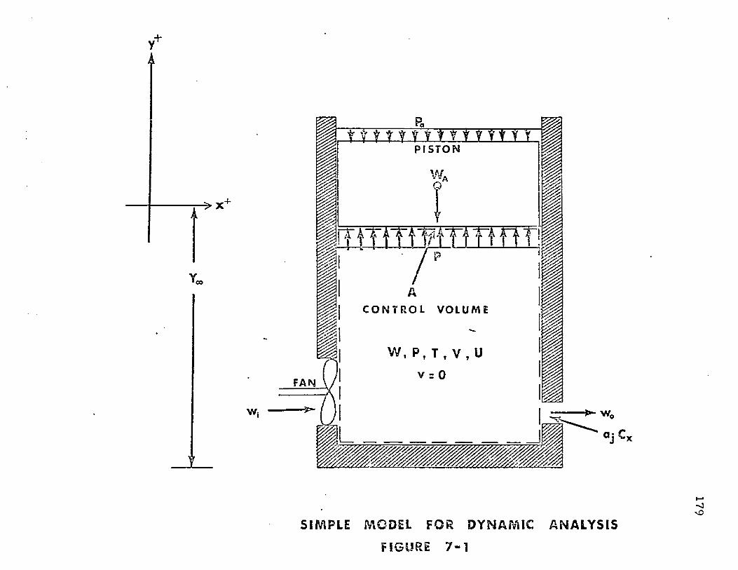
-> X"
w ,
t fr fr y y y y t Y V Y Y Y Y YP I S T O N
/C O N T R O L VOLUME
W , P t T , V , U
v = 0
S I M P L E M O D E L F O R D Y N A M I C A N A L Y S I S
F I G U R E 7 - 1
179
180
j refers to th e t ru n k
k refers t o th e co rn e r t ru n k segm en t
n a rb i tra ry
0 refers to f low o u t o f th e c o n tro l vo lum e
r refers to stall co n d it io n o f th e fan
s refers to th e side t ru n k segm ent
1 refers to th e segm en t 2 -j
2 refers to th e segm en t 2 2
3 refers to th e segm en t 2 3
7 .2 S im ple D ynam ic Model
7.2.1 A p p ro a c h and A ssum ptions
A g rea tly sim plified m odel o f th e a ir cushion t ru n k is sh o w n in Figure 7-1. T he
figure show s an insu la ted cy linder of gas. T he gas is being com pressed b y a p iston falling
u n d e r th e a c t io n of gravity . During th e com pression process, air m ay en te r th e con tro l
vo lum e f ro m a fan and m ay leave th e vo lum e th ro u g h an orifice.
T h e a ssu m p tio n s fo r th e analysis are as follows:
7 .2 .1 .1 T h ru s t f rom the e x h a u s t gas is neglected.
7 .2 .1 .2 A d iaba tic expansion or com pression occurs in th e con tro l vo lum e.
7 .2 .1 .3 T h e change in heigh t o f th e gas f low ing th ro u g h th e c o n tro l vo lum e is
neglected .
7 .2 ,1 .4 T h e e n th a lp y of th e in p u t a ir equals th e e n th a lp y of th e e x h a u s t air.
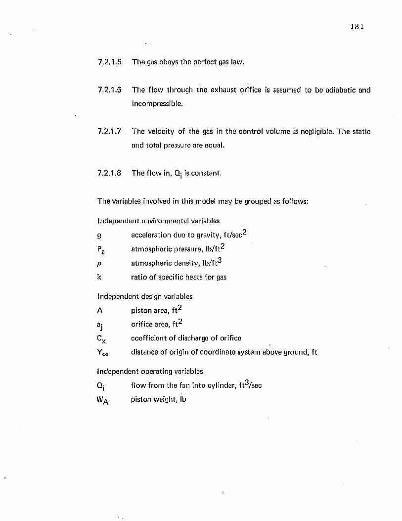
181
7 .2 .1 .5 T he gas obeys th e perfec t gas law.
7 .2 .1 .6 T he flow th rough th e exhaust orifice is assum ed to be ad iaba tic and
incompressible.
7 .2 .1 .7 T he velocity o f th e gas in th e con tro l vo lum e is negligible. T he sta t ic
and to ta l pressure are equal.
7 .2 . 1 . 8 The flow in, Qj is cons tan t.
The variables involved in th is model m ay be g rouped as follows:
Independen t environm enta l variables
g acceleration due to gravity, f t / s e c ^
Pa a tm ospheric pressure, lb /f t^
p a tm ospheric density , lb /f t^
k ra t io of specific heats for gas
In dependen t design variables
A p iston area, f t^
aj orifice area, f t^
Cx coeff ic ien t of discharge of orifice
Yoo distance of origin of coo rd ina te system above g round , f t
In dependen t opera ting variables
Qj f low from the fan in to cylinder, f t^ /sec
piston weight, lb
182
T im e d e p e n d e n t variables
p (t) c o n tro l vo lu m e p ressure , lb / f t^
T (t) c o n tro l vo lu m e gas te m p e ra tu re , ° R
V(t)q
c o n tro l vo lum e, f t °
W(t) co n tro l vo lum e gas w e igh t, lb
y(t} p is ton pos it ion , f t
y (t) p iston ve loc ity , f t / s e c
In o rd e r t o d e te rm in e th e varia t ion o f th e d e p e n d e n t variables w ith t h e t im e
pa ra m ete r , six in d e p e n d e n t e q u a t io n s are necessary . T hese e q u a t io n s m ay be d e v e lo p e d by
ap p ly in g th e fo llow ing laws a n d p rincip les :
(1) N e w to n 's se co n d law app lied to th e free p is ton b o d y in th e vertical
d i re c t io n gives:
. y ( t) = f[P(t)]
(2) G e o m e tr ic c o m p a t ib i l i ty app lied to th e c o n tro l v o lu m e gives:
y (t) = f [V (t ) ]
(3) A n energy ba lance app lied to th e c o n tro l vo lum e gives:
T ( t) = f[W(t}, V ( t) , P(t)]
<4) T h e p e r fe c t gas law gives:
T ( t) = f[W (t), V (t) , P{t)]
(5) T h e c o n t in u i ty a n d energy p r inc ip les app lied t o f lo w th ro u g h th e
orif ice and fan gives:
183
W(t) = f[P(t) ]
It may be no ted th a t the equa tion resulting from principles {3} and (4) rnay be
com bined to e liminate T{t). An additional equa tion defining y(t) = f [y ( t) ] m ay be
in troduced to eliminate y(t) f rom the relationship in principle ( 1 ).
7.2 .2 N ew ton 's Second Law
N ew ton 's second law may be applied to the piston shown in Figure 7-1. The result
Equation (7-1) equates the vertical external forces acting on the p iston to the
p ro d u c t of th e mass and acceleration in the vertical d irection. The th rus t force is neglected
(Assumption 7 .2.1.1).
7.2 .3 G eom etric Com patib ility
Since th e piston area is constan t, th e relationship betw een the piston height and
the control volum e is linear. It is evident f rom th e geom etry of Figure 7-1 tha t:
is:d^y
+ A (P — Pa ) (7-1)
V = A ( Y „ + y) (7-2)
7 .2 .4 Energy Balance Applied to th e Control Volum e
T o com ple te the problem , a force (pressure) versus deflection relationship m ust
be derived from therm odynam ic considerations. T he first law of therm odynam ics may be
applied to the contro l volume shown in Figure 7-1 as follows:
184
change in s to red energy = energy in — energy o u t + w o rk in + heat in
Based upon A ssum ptions 7 .2 .1 .2 and 7 .2 .1 .3 the heat in is zero and th e change in
potentia l energy o f th e gas flowing th rough th e cy linder is zero. T he energy balance then
becomes:
“ j“ “ <h i w i ~ ho w o> + = 0 (7' 3)
T he conservation-of-mass law m ay be applied to the contro l volume. The resulting
equa tion equa tes th e change o f mass of th e gas in th e contro l volum e to th e difference
betw een in flow and o u t flow. The results are:
dW = Wj - wQ (7-4)d t
T he application of A ssum ption 7 .2 .1 .4 gives:
hj = hQ (7-5)
For a perfect gas (Assum ption 7 .2 .1 .5 ) , internal energy (u) and en tha lpy (h) can
be represented as:
U = W u (7-6)
du = Cv dT (7-7)
PVh = u + . (7-8)W
S ubstitu ting E quations (7-4) th rough (7-8) in Equation (7-3) and dividing the
resulting eq u a tio n by C v WT, gives th e following results:
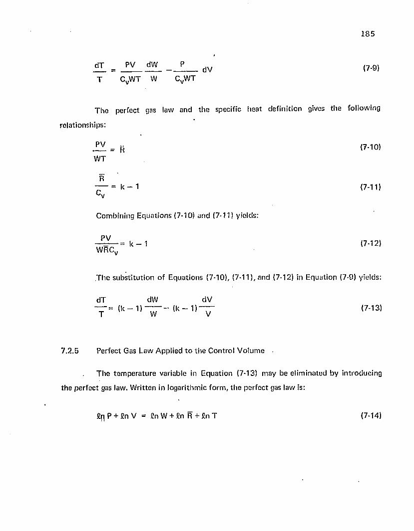
185
£ L = - J L _ dV (7-9)T CVW T W CVWT
T h e p e rfe c t gas law an d th e specific h e a t d e f in i t io n gives th e fo llow ing
re la tionsh ips :
— = H ( 7 *1 0 1
WT
R— = k - 1 (7-11)c v
C o m b in in g E q u a t io n s (7-10) a n d (7-11) yields:
PV— —------ = k - 1 (7-12)W RCy
T h e s u b s t i tu t io n o f E q u a t io n s (7-10), (7-11), a n d (7-12) in E q u a t io n (7-9) y ields:
d T dW dV
T = ( k - 1 l T T ' ( k - , , ~ ( 7 - 1 3 1
7 .2 .5 P e rfec t Gas Law A pp lied t o t h e C o n tro l V o lu m e •
T h e t e m p e ra tu re variable in E q u a t io n (7-13) m ay be e lim in a ted by in tro d u c in g
th e p e r fe c t gas law. W rit ten in logar i thm ic fo rm , t h e p e rfe c t gas law is:
fip P + fin V = fin W + fin R + fin T (7-14)
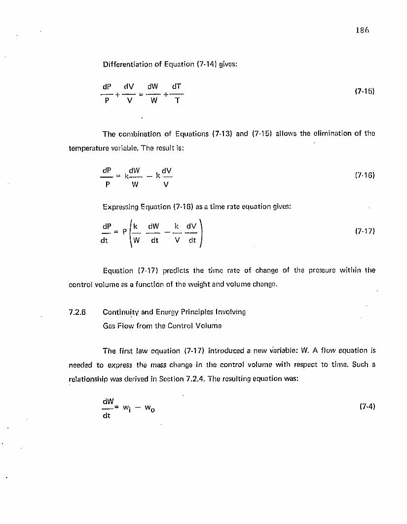
186
D ifferen tia t ion o f E quation (7-14) gives:
dP dV dW dT
W T(7-15)
T h e c o m b in a tio n of E quations (7-13) and (7-15) allows the e lim ina tion of the
tem p e ra tu re variable. T he result is:
dP ,d W . dV— = k---------- k — (7-16)
W V
Expressing Equation (7-16) as a t im e rate equa tion gives:
\dP
d t= P
k dW
W d t
k dV
V d t(7-17)
E quation (7-17) predicts th e t im e rate o f change of th e pressure w ith in th e
contro l volum e as a func t ion of th e w eight and volum e change.
7 .2 .6 C on tinu ity and Energy Principles Involving
Gas F low from th e Control V olum e
T h e first law equa tion (7-17) in troduced a new variable: W. A flow equa tion is
needed t o express th e mass change in th e con tro l vo lum e with respect to t im e. Such a
rela tionship was derived in Section 7 .2 .4 . T he resulting equa tion was:
d W ,-7 = wj — w Q (7-4)d t
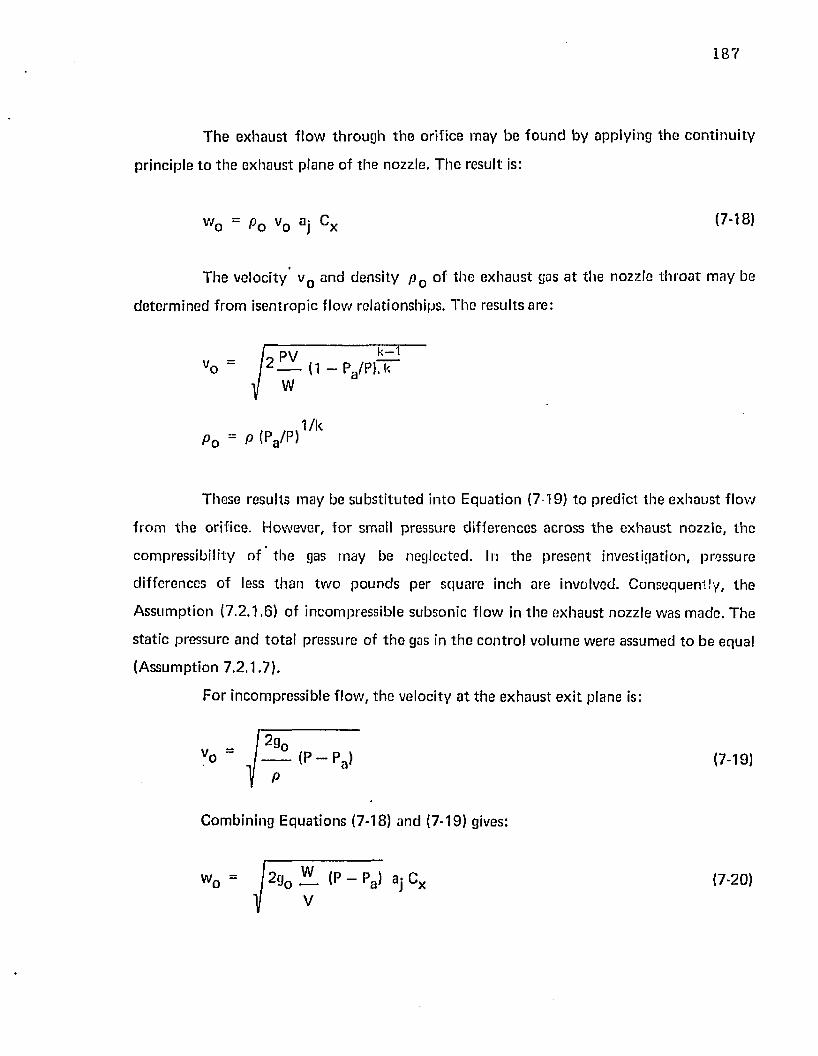
187
T h e exhaust f low th rough th e orifice m ay be fo u n d by applying th e c o n tin u i ty
principle to th e exhaust p lane of the nozzle. T he result is:
These results m ay be su b s ti tu ted in to Equation (7-19) to p red ic t the exhaust f low
from th e orifice. However, fo r small p ressure d ifferences across th e exhaust nozzle, th e
com pressib ili ty of the gas may be neglected. In th e p resen t investigation, pressure
differences o f less than tw o po u n d s per square inch are involved. C onsequently , th e
A ssum ption (7 .2 .1 .6 ) of incom pressib le subsonic flow in th e exhaust nozzle was m ade. T he
s ta t ic pressure and to ta l pressure of th e gas in th e con tro l vo lum e were assumed to be equal
(A ssum ption 7 .2 .1 .7 ) .
w o “ Pq vo a j ^o vo j x (7-18)
T he velocity v Q and density p Q of th e exhaust gas a t the nozzle th ro a t m ay be
de te rm ined from isen tropic f low relationships. T he results are:
v,o
P0 = P (pa /p)1 /k
For incom pressib le flow, th e velocity a t th e exhaust ex it plane is:
(7-19)
Com bining E qua tions (7-18) and (7-19) gives:
wo ■ I290 E ( P - P a) aj C„ (7-20)
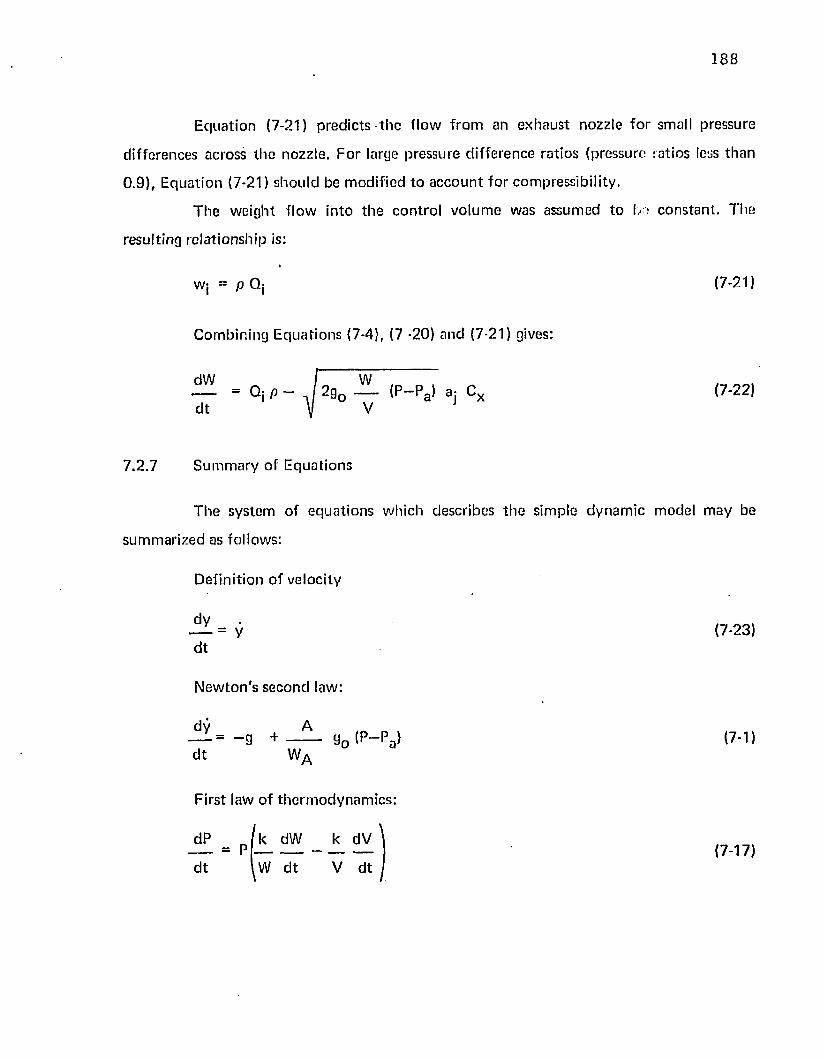
188
E q u a tio n (7-21) p red ic ts t h e f low f ro m an ex h au st nozzle fo r small pressure
d ifferences across th e nozzle. F o r large p ressure d iffe rence ra tios (pressure ratios less th a n
0 .9 ) , E qua tion (7-21) shou ld be m odif ied to a c c o u n t fo r com pressib ili ty .
T h e w eight f low in to th e con tro l vo lum e was assum ed to b c o n s t a n t . T he
resulting re la tionsh ip is:
w: = p Q: (7-21)
C om bin ing E qua tions (7-4), (7 -20) and (7-21) gives:
dW W , Qj p — - J 2 g0 ----- (p “ pa^ ajdt V V J
(7-22)
7 ,2 .7 S u m m a ry of E qua tions
T h e sys tem of e q u a t io n s w hich describes t h e sim ple d y n a m ic m odel m ay be
su m m arized as follows:
D efin it ion of velocity
d t= y (7-23)
N e w to n 's s econd law:
dv A— = - g + — g0 <p - p a>d t WA
(7-1)
First law o f th e rm o d y n am ic s :
dP
d t
_ p k dW _ k dV
W d t V d t(7-17)
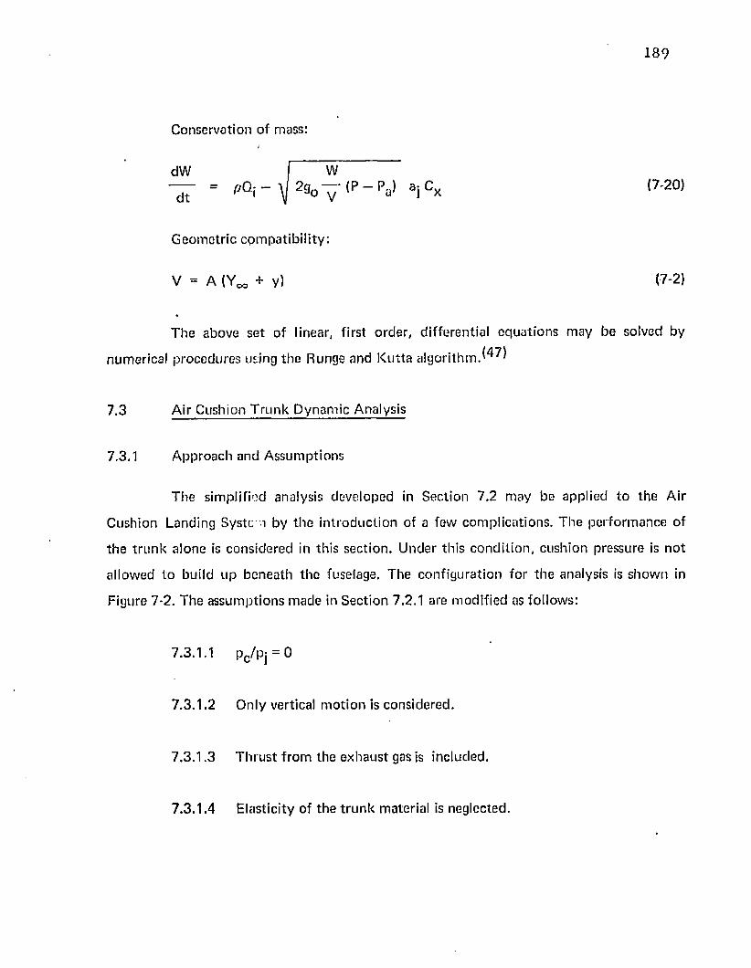
189
C onservation of mass:
dW W— = P0.i - 2g0 y I P - P al a j Cx (7-20)
G eo m etr ic com p a t ib i l i ty :
V = A (Ym + y) (7-2)
T h e above se t o f linear, first o rder , d iffe ren tia l e q u a t io n s m ay be solved by
num erica l p rocedu res using th e Runge and K u tta a lgo rithm .
7.3 Air Cushion T ru n k D ynam ic Analysis
7.3.1 A p p ro ach and A ssum ptions
T he sim plified analysis developed in S ec tion 7.2 m ay be applied to th e Air
Cush ion Landing Sys tem by th e in t ro d u c tio n of a few com plica tions . T h e p e rfo rm an ce of
th e t ru n k a lone is cons ide red in th is sec t ion . U nder th is co n d it io n , cush ion pressure is n o t
a llow ed to build up b en ea th th e fuselage. T he con fig u ra t io n fo r th e analysis is sh o w n in
Figure 7-2. T he assu m p tio n s m ade in S ec tion 7.2 .1 are m od if ied as fo llow s:
7.3.1.1 pc/pj = 0
7 .3 .1 .2 O n ly vertical m o tio n is considered .
7 .3 .1 .3 T h ru s t f rom th e e x h a u s t gas is included .
7 .3 .1 .4 E lastic ity of th e t r u n k material is neglected .
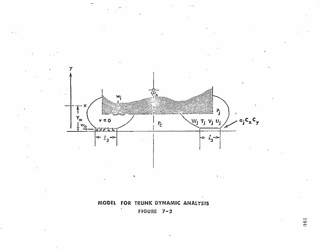
yi i
M OD EL FOR T R U N K D Y N A M I C A N A L Y S I S
FIGURE 7 - 2
190
191
7 .3 .1 .5 T h e f lo w in, Q j , is a k n o w n fu n c t io n o f Pj .
7 .3 .1 .6 T h e d is tance above th e g ro u n d a t w h ich th e t ru n k begins to in f luence
th e d y n a m ic response o f th e a irc ra f t is des igna ted Y . M ore precisely,
Yco is th e p o in t above th e g round a t w h ich A 3 = 0 .
7 .3 .1 .7 T he c o o rd in a te sys tem is se lec ted as sh o w n in Figure 7-2 such t h a t y -
0 a t d is tance above th e g ro u n d . W ith th is se lec tion , t h e fo llow ing
re la t io n sh ip holds: Y 0 = —y fo r all y < 0 .
7 .3 .1 . 8 T h e fan speed is assum ed t o be c o n s ta n t .
It m ay be n o ted th a t th e re are five m ajo r d iffe rences b e tw e en th e sim ple m odel of
S ec t io n 1.1 an d th a t o f th e a ir cu sh io n t ru n k . These d iffe rences are as fo llow s:
(1) T h e t r u n k m odel has a t h r u s t fo rce ac ting u p w a rd d u e to t h e change in
m o m e n tu m o f th e e x h a u s t gas.
(2) T h e f o o tp r in t (p is ton) a rea {A3 ) is n o t a c o n s ta n t , b u t is a f u n c t io n of
V-
(3) T h e c o n tro l vo lu m e is a n o n l in e a r f u n c t io n o f Y ra th e r th a n a s im ple
l inear fu n c t io n .
(4) T h e e ffec tive area o f d ischarge o f t h e o r if ice is n o t a c o n s ta n t , b u t is a
fu n c t io n o f y.
(5) T h e f lo w f ro m th e fan ( Q j ) is n o t a c o n s ta n t , b u t r a th e r a fu n c t io n o f
t r u n k pressure (pj).
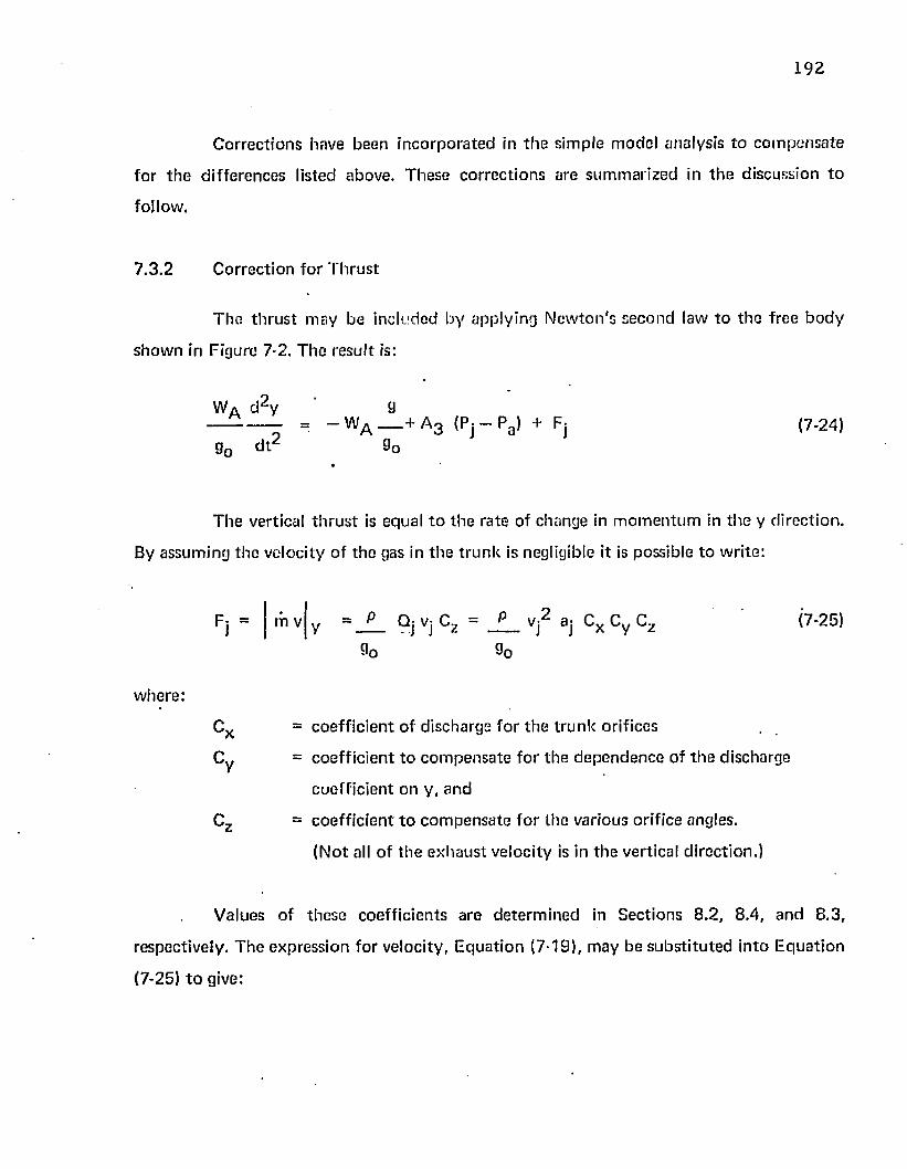
1 9 2
C o rrec t io n s have been in c o rp o ra te d in th e s im ple m odel analysis to c o m p e n s a te
fo r t h e d if fe re n c es listed above. T hese c o rre c t io n s are su m m a riz ed in t h e d iscuss ion to
fo llow ,
7 .3 .2 C o rrec t io n fo r T h ru s t
T h e th ru s t m ay be inc luded b y app ly ing N e w to n 's se co n d law t o th e f ree b o d y
s h o w n in F igure 7-2. T h e resu l t is:
T h e vertical t h r u s t is equal t o th e ra te of change in m o m e n tu m in t h e y d irec tio n .
By assum ing th e ve loc i ty o f th e gas in t h e t r u n k is negligible it is possib le to w ri te :
" WA — + A 3 (Pj - Pg) + Fjg
(7-24)
g0 d t2
Fj = m v y (7-25)
w here :
C x = c o e ff ic ie n t o f d ischarge fo r t h e t ru n k orif ices
C y = c o e ff ic ie n t t o c o m p e n s a te fo r th e d e p e n d e n c e o f t h e d ischarge
c o e ff ic ien t o n y , a n d
Cz = c o e ff ic ie n t t o c o m p e n s a te f o r th e various o rif ice angles.
(N o t all o f th e e x h a u s t ve loc ity is in th e vertical d irec tion .)
V alues o f th ese coe ff ic ien ts a re d e te rm in e d in S ec t io n s 8 .2 , 8 .4 , a n d 8 .3 ,
respective ly . T h e exp ress ion fo r ve loc ity , E q u a t io n (7-19), m ay b e s u b s t i tu te d in to E q u a t io n
(7-25) t o give:
193
Fi = 2 (pj - Pa> ai Cx Cy C,a' uj wx y z (7-26)
E q u a t io n (7-26) m ay b s s u b s t i tu te d in to E q u a t io n (7-24) t o give:
----------_ = _ w A — t* A 3 (Pj - Pa ) + 2 (Pj - Pa ) aj Cx Cy Cz {7.27)
90 d t ' 9 0
a d y 9
E q u a t io n (7-27) e q u a te s th e su m o f t h e vertical fo rces o n th e a irc ra f t (w eight,
f o o tp r in t p ressure an d th ru s t ) to th e p r o d u c t o f t h e a ir c ra f t m ass a n d th e vertical
a cce le ra tio n . Th is e q u a t io n provides th e req u ired c o rre c t io n fo r j e t th ru s t .
7 .3 .3 C o rrec t io n fo r F o o tp r in t A rea
f o o tp r in t length ( 6 3 ) p red ic te d by th e c o m p u te r p ro g ram deve loped in S ec tion 4 .5 . I t was
n o te d in S ec t io n 4 .5 t h a t £ 3 is d e p e n d e n t o n th e t r u n k leng th £ , th e a t t a c h m e n t p o in ts
(a,b) an d on pc /p j an d Y Q. It is ev iden t f ro m Figure 4-8 t h a t d i f f e re n t sec t ions of th e t r u n k
on an a c tu a l m odel have d i f fe re n t a t t a c h m e n t p o in ts a n d t r u n k lengths. H ow ever, it is
possib le t o s e p a ra te th e t r u n k in to a n u m b e r o f se g m e n ts w h ich have a p p ro x im a te ly th e
sam e t r u n k leng th an d a t t a c h m e n t po in ts . If th e e ffec tive length o f th e n ^ 1 s e g m e n t is Ln
an d th e r e a re a to ta l of m segm en ts , t h e to ta l f o o tp r in t a rea is:
E q u a t io n (7-28) p red ic ts th e to ta l f o o tp r in t a rea o f t h e t r u n k as th e sum o f th e
f o o tp r in t a reas o f all th e t ru n k se gm en ts . T h e f o o tp r in t leng th £ 3 is a k n o w n fu n c t io n of
Y q a n d p c /p j . F o r t h e case co n s id e red in th is se c t io n , Pc/Pj = 0 . T h e varia t ion o f £ 3 w ith
T h e fo o tp r in t a rea (A 3 ) m ay be d e te rm in e d ana ly t ica lly f ro m th e values of
(7-28)
ft
19 4
Y q fo r pc /p j “ 0 was s h o w n in Figures 4-21 a n d 4 -22 . T h e fo rm e r f igure is for a side t r u n k
segm en t a n d th e la t te r is fo r an en d t r u n k segm ent.
T h e value of Ln is a c o n s ta n t fo r s tra ig h t t r u n k se g m e n ts such as t h e side se g m e n t
sh o w n in F igure 4-8. How ever, fo r curved segm en ts such as th e en d se g m e n t s h o w n in Figure
4-8, Ln is d e p e n d e n t on pc/p j a n d YQ, T h is d e p e n d e n c e m ay be ca lcu la ted f ro m th e
c o m p u te r p rog ram given in A p p e n d ix III. Using th e above p ro ce d u re , it is possib le to
d e te rm in e A 3 as a fu n c t io n o f Y Q fo r th e t r u n k o n a given m odel.
7 ,3 .4 C o rrec t io n fo r T r u n k V o lu m e C hange
T h e t r u n k vo lu m e (Vj) m ay be d e te rm in e d a n a ly t ica lly f ro m th e values of
cross-sec tion area (Aj) | j red ic ted by th e c o m p u te r p rogram deve loped in S ec t io n s 4 .5 and
4 .6 . T h e t r u n k m ay be d iv ided in to a n u m b e r o f segm en ts in a m a n n e r s im ilar io th a t
desc r ibed in S e c t io n 7 .3 .3 . If t t ie effec tive length o f th e n 1 *1 se g m e n t is Kn an d th e re are a
to ta l o f m segm en ts , t h e to ta l t r u n k vo lu m e is:
r 1
Vj * \ (Aj) n Kn (7-29)
T h e t r u n k se g m e n t cross-sec tional area (Aj) is a k n o w n f u n c t io n o f Y Q a n d Pc /pj-
T h e varia tion o f Aj w ith Y Q fo r p c/p j = 0 was sh o w n in F igures 4 -23 an d 4 -24 . T h e fo rm e r
figure is fo r a s ide t ru n k se g m e n t a n d th e la t te r is f o r a n e n d t r u n k segm en t.
T h e value o f K n is c o n s ta n t fo r s t r a ig h t t r u n k segm en ts such as t h e side t r u n k
se g m e n t s h o w n in Figure 4-8. H ow ever, t h e en d t r u n k se g m e n t is a vo lum e o f revo lu t ion .
F o r a v o lu m e of rev o lu t io n , th e e f fe c t leng th m ay b e d e f in ed as fo llow s:
(7-30)
195
w here
a.
r,n
n
= rad iu s f ro m t h e c e n te r o f rev o lu t io n t o t h e c e n tro id of t h e a rea
Aj fo r t h e n ^ t r u n k se g m e n t
= angle o f rev o lu t io n for th e vo lu m e o f th e n ^ t r u n k se g m e n t
T h e values o f rn an d a n m ay be ca lcu la ted f ro m th e g e o m e try o f t h e pa r t icu la r
m odel a n d t r u n k segm en t.
Using th e above p ro c e d u re it is possib le to d e te rm in e Aj as a f u n c t io n o f Y Q fo r
th e t r u n k o n a given m odel.
7 .3 .5 C o rrec t io n fo r V ariab le Discharge Area
A s th e t r u n k is pressed against th e g ro u n d , th e f low f ro m t r u n k e x h a u s t orif ices in
t h e f o o tp r in t area is red u c e d . A discharge co e ff ic ien t , Cy, has been in t ro d u c e d t o a c c o u n t
fo r t h e resu lting d e p e n d e n c e o f th e t r u n k e x h a u s t f lo w o n th e vehicle h e igh t (Y c ).
T h e resu lting f lo w re la t io n sh ip is:
w h e re Cy is a f u n c t io n o f YQ.
T h e value of Cy is d e te rm in e d b y c o m p u t in g t h e f low f ro m th e va rious t r u n k
se gm en ts £ j , ^ anc* ^ 3 s h o w n in Figure 4-2. T h e resu lting f low s are des ig n a ted Q-j, Q 2 ,
a n d Qg, a n d m ay be c o m p u te d as fo llow s:
(7-31)
(7-32)
196
C>2 = if 290 (Pjl 32 Cx (7-3S)
° 3 = IPj) a3 ' Cx C/-34)
Qj — Q-| + Q 2 Q3 (7-35)
T h e values o f a-j an d a 2 a re d e te rm in e d b y th e to ta l t r u n k orif ice area in segm en ts
£ 1 an d £ 2 respective ly . T h e value o f a g ' is d e te rm in e d by th e area w hich c o n t ro l s t h e f lo w
f ro m t r u n k se g m e n t £ 3 .
If t h e area b e tw e e n th e t r u n k an d th e g ro u n d is less th a n th e t r u n k orif ice area 8 3 ,
t h e n f lo w is c o n tro l le d by th e g ro u n d c lea rance ra th e r th a n b y th e t r u n k area.
C o n se q u e n tly , t h e effec tive f lo w area fo r seg m en t £ 3 m ay be w r i t te n :
8 3 ' = w h ichever is sm aller (7-36)
2S3 d _ D
T h e value o f 0 3 m ay be a p p ro x im a te d b y th e p r o d u c t o f th e f o o tp r in t area (A 3 )
a n d th e p o ro s i ty o f t h e t r u n k £ in th e f o o tp r in t area. T h e resu l t is:
(7-37)
T h e p o ro s i ty o f t h e t r u n k £ is d e f in ed as th e ra t io o f o rif ice area t o to ta l area in
th e sec t io n o f t h e t ru n k c o n ta in in g th e orifices.
197
T he to ta l je t area o f the t ru n k is th e sum of th e area in the th ree segments,
aj = ai + a3 + 83 (7-38)
' A n expression fo r Cy is ob ta ined by com bining Equations (7-31), (7-32), (7-33),
(7-34), and (7-35). T he result is:
a 1 + a 2 + a3*Cy = -------------------- (7-39)
aj
It is evident f rom E quation (7-39) th a t Cy = 1.0 w henever a 3 ' = a3 .
T h r equa tion for Cy m ay be fu r th e r simplified by subs ti tu ting Equations (7-37)
and (7-38) in to (7-39). T he result is:
a: - A 3 £ + a 3 'Cy = J ______________ (7-40)
aj
In E quation (7-40), aj and £ are constan ts. A 3 is a know n func t ion of Y 0 as
developed in Section 7.3.3. T he value of a 3 was defined as follows:
whichever is less (7-36)2 S 3 d C D/C X
T h e values o f S3 , C x , an d C q are constan ts . T he value o f d is d e p e n d en t on a
num ber of variables including YQ. An assessment o f th e value of d is p resented in th e
rem ainder of th is section.
198
A n es tim a te o f th e je t he igh t d varia tion w ith YQ has been m ade based u p o n an
analysis, c o n d u c te d by H an ' o f idealized f low in a channel w ith in jec tion f rom a
p o ro u s wall. In his analysis, Han d e te rm in ed th e pressure d is t r ib u t io n in a channel of th e
con figu ra t ion show n in Figure 7-3. T h e in d e p e n d e n t variables fo r th is analysis w ere d , £ 3 ,
P j , and fj. T h e la t te r q u a n t i ty is th e effective wall po ro s i ty and m ay be expressed by th e
ra t io 8 3 ^ 3 . T he to ta l vertical fo rce per u n i t length w hich is developed in th e fo o tp r in t area
can be de te rm in e d by in tegrating th e pressure over th e f o o tp r in t length. Using a t ru n k
pressure o f 8 0 psf an d the p o ro s i ty value fo r th e m odel side t ru n k given in T ab le 5-1, th e
fo o tp r in t fo rce was d e te rm in e d as a fu n c t io n of jot he igh t and f o o tp r in t length. T h e results
are p lo t ted in Figure 7-4.
Figure 7-4 p resen ts th e load-deflection charac te r is t ics of th e je t fo r various
fo o tp r in t lengths. T he actual je t height is d e te rm in ed by th e load w hich th e je t m ust su p p o r t
fo r a given t ru n k configu ra t ion .
A free b o d y d iagram of a t ru n k configu ra t ion is sh o w n in Figure 7-5. Force
equ il ib r ium app lied in t h e y d irec tion gives:
Pj i! 3 - F 3 - 2 T t sin \pt = 0 (7-41)
T h e value o f T t was given by E q u a tio n (4-1).
T t = R l P j (4-1)
Com bin ing E q u a tio n s (4-41) and (4-1) gives:
F 3 = pj (C3 - 2 R-j sin ^ t ) (7-42)
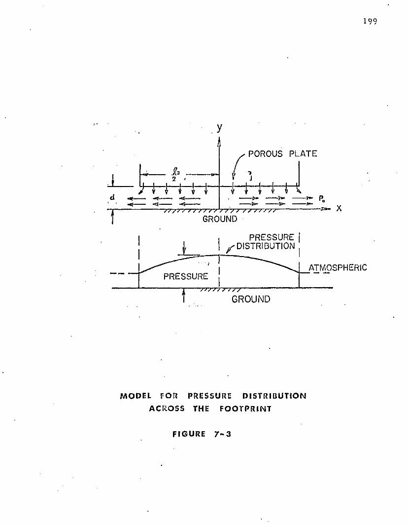
199
POROUS PLATE
X/ / S *7 V V 7 / S V V V / /
GROUND
PRESSUREDISTRIBUTION
ATMOSPHERICPRESSURE
7 7 --------------GROUND
m o d e l f o r p r e s s u r e d i s t r i b u t i o n
A C R O S S THE F O O T P R I N T
F I G U R E 7 - 3
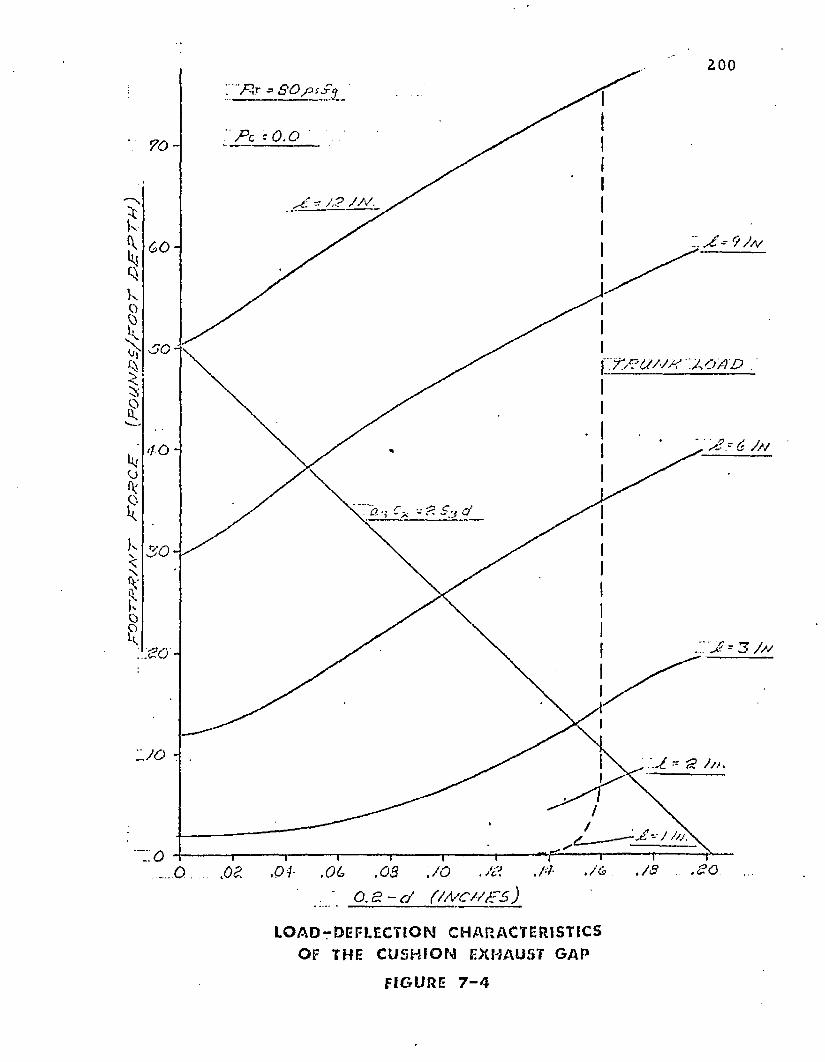
200
>£* 9 / a/
O / I D
J? - 6 9/ /
,01- ,OL .08 JO JZ
LOAD-DEFUCTION CHARACTERISTICS OF THE CUSHION EXHAUST GAP
FI GURE 7 - 4
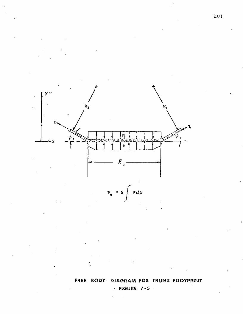
•S?
F3 = S I P d x
FREE B O D Y D I A G R A M FOR T R U N K F O O T P R I N T
• FIGURE 7 - 5
2 02
F o r th e analysis o f t h e t r u n k sh a p e p re se n ted in S ec t io n 4 .5 , \!>t w as a ssu m ed to
be zero . How ever, th is analysis was m ad e fo r a t ru n k se c t io n w ith f ree edges. A t r u n k o n a
th ree -d im en s io n a l m odel is c o n s tra in e d by th e cu rv a tu re o f th e t r u n k in t h e periphera l
d i re c t io n . C o n se q u e n t ly , i t is possib le f o r a f in i te angle t o ex is t a t th e edge o f t h e f o o tp r in t .
S u ch an angle has b e e n observed on a th ree -d im en s io n a l m o d e l . A value o f = 4 °
c o n s ta n t gives rea so n a b le a g re e m e n t w ith observed resu lts on th e d y n a m ic m odel. Using th e
a ssum ed value o f i^t , t h e values o f F 3 c o m p u te d f ro m E q u a t io n (7-42) are s h o w n as th e
load line on F igure 7-4.
T h e j e t he igh ts a t w h ich 3 3 = 2 8 3 d a re also s h o w n on th e curve. F ro m th e resu lts
p re se n te d in F igure 7-4, it is a ssum ed th a t d = c o n s ta n t f o r values o f C 3 g rea te r th a n a b o u t
2 inches.
7 .3 .6 C o rrec t io n fo r F low f ro m th e Fan
T h e f lo w f ro m th e fan is d e p e n d e n t u p o n th e fan speed an d th e e x h a u s t p ressure.
T h is varia t ion m ay be d e te rm in e d b y s ta n d a rd fan ca lib ra t io n tes ts . Such a t e s t is descr ibed
in S e c t io n 8 . 6 an d th e te s t resu lts are sh o w n in F igure 8-3.
F o r t h e p u rp o se s o f th is analysis, th e fan speed is assum ed to be c o n s ta n t du r ing
land ing im p a c t (A ssu m p tio n 7 .3 .1 .7 ) .
7 .3 .7 S u m m a r y o f E q u a t io n s
T h e ch an g es req u ired t o a p p ly t h e sys tem o f e q u a t io n s deve loped in S ec t io n 7 .2
t o t h e a ir c u sh io n t r u n k sy s te m have been deve loped in S ec t io n s 7.3.1 th ro u g h 7 .3 .6 . T h e
resu lting e q u a t io n s m ay be s u m m a riz e d as fo llow s:
D ef in i t ion of ve loc ity
d y— = y (7*23)d t
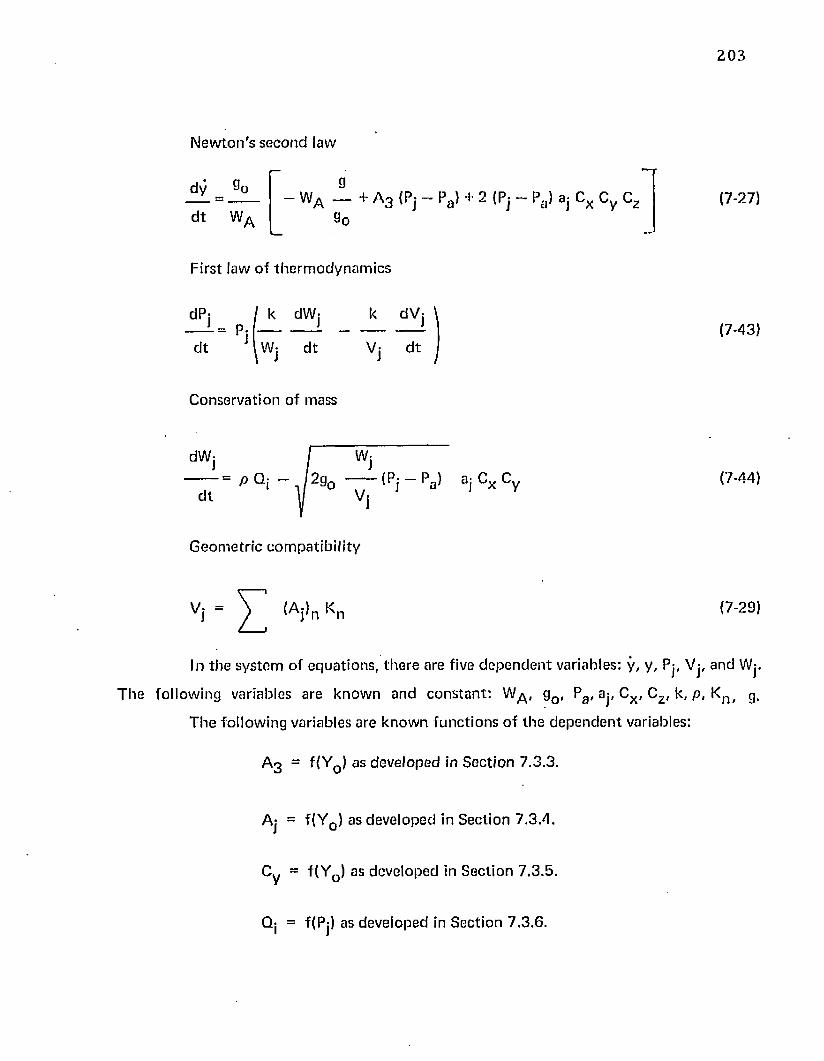
203
N e w to n 's s e c o n d law
d y
d t WA
- WA - + A 3 {Pj - Pa > + 2 {Pj - Pa ) aj Cx Cy Cz
9o(7-27)
F irs t law o f th e r m o d y n a m ic s
dP:= P :
d t
k dW k dV
Wj d t V: d t(7-43)
C onse rva t ion o f mass
dW: Wj
P Qj / 2 g o (Pj Pa ) aj Cx Cy d t A/ Vj
(7-44)
G e o m e tr ic c o m p a t ib i l i ty
(A j)n Kn (7-29)
In th e sy s te m of e q u a t io n s , th e re are five d e p e n d e n t variables: y , y , Pj, Vj, and Wj.
T h e fo llow ing variab les are k n o w n an d c o n s ta n t : W ^ , gQ, Pa , aj, Cx , Cz , k, p, Kn# g.
T h e fo llow ing variab les a re k n o w n fu n c t io n s o f th e d e p e n d e n t variables:
A g = f{ YQ) as d eve loped in S ec t io n 7 .3 .3 .
Aj = f (Y 0 ) as deve loped in S ec tion 7 .3 .4 .
Cy = f (Y0 ) as deve loped in S ec t io n 7 .3 .5 .
Qj = f(Pj) as deve loped in S ec t io n 7 .3 .6 .
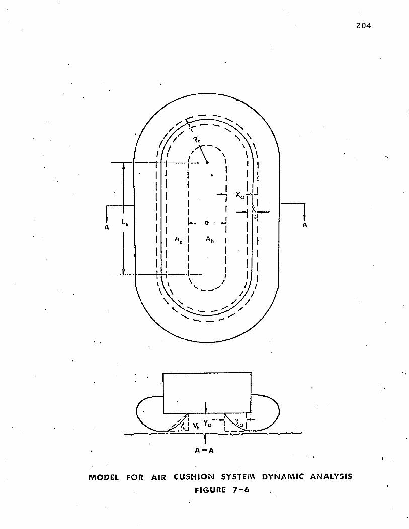
2 0 4
___
A - A
M O D E L FOR AI R C U S H I O N S Y S T E M D Y N A M I C A N A L Y S I S
FI GURE 7 - 6
T he system of equa tions and func t ions described in th is section has been
program m ed and solved on a digital c o m p u te r using the Runge and K utta a lg o r i th m .^ ? )
T he c o m p u te r results have been com pared w ith experim ental results in C hap ter 8 .
7 .4 C om plete Air Cushion System D ynam ic Analysis
7.4.1 A pproach and A ssum ptions
T he analysis developed in Sections 7 .2 and 7.3 m ay be applied to th e com ple te air
cushion system by in troduc ing relationships to acco u n t fo r the e ffec t of cushion pressure on
th e system response. The configuration fo r the analysis is shown in Figure 7-6. T he
assum ptions m ade in Section 7.3.1 are m odified as follows:
7.4.1.1 T he cushion pressure is allowed to build up so th a t p c /pj V 0 .
■ 7 .4 .1 .2 T he m odel is of th e ty p e show n in Figure 7-6. The t ru n k cross section is
th e sam e a t any section.
7 .4 .1 .3 T he t ru n k configuration is identical to th e side t ru n k whose p roperties
were listed in Table 5-I.
A num ber of additional sim plifying assum ptions are included in the sections to
follow.
T he equa tions of m otion developed in Section 7 .3 m ay be applied t o a com ple te
cu sh ion - trunk system by th e in troduc tion o f co rrec tions fo r cushion pressure.
T he necessary correc tions are as follows:
(1) Correction o f th e second law equa tion fo r the reaction force from th e
cushion pressure.
(2) P red ic tion o f t h e area over w h ich th e cush ion p ressure acts.
(3) P red ic t io n o f t h e cu sh io n p ressure .
(4) P red ic tion o f th e cu sh io n volum e.
(5) P red ic tion o f th e cu sh io n f low .
(6 } P red ic tion o f th e in f luence o f cu sh io n pressure on t r u n k flow .
(7) P red ic tion o f t h e in f luence o f cu sh io n pressure on t r u n k f o o tp r in t area .
(8 ) P red ic t ion o f th e in f luence o f cu sh io n p ressure on t r u n k vo lum e.
(9) P red ic t ion o f th e in f luence o f cu sh io n p ressure on vertica l th ru s t .
T hese c o rre c t io n s have b e e n deve loped in th e sec t ions to fo llow .
7 .4 .2 C ush ion R eac tion
T h e cush ion p ressu re reac tion m ay -be inc luded in t h e second law e q u a tio n ,
E q u a t io n (7-27), b y t h e in t ro d u c t io n o f an add it io n a l fo rce te rm . T h e resu lting e q u a t io n is:
207
E q u a t io n (7-45) e q u a te s t h e sum o f th e vertical fo rces o n th e a irc ra f t (weight,
f o o tp r in t fo rce , cu sh io n fo rce an d th ru s t ) t o t h e p r o d u c t o f t h e m ass a n d th e vertical
acce le ra tion .
7 .4 .3 C ush ion S u p p o r t A rea
» •
T h e cu sh io n s u p p o r t area (Ac ) is a f u n c t io n o f b o th Y Q an d p c /p j. Figure 7-G
sh o w s t h a t th e cu sh io n area m ay be d ivided in to tw o pa rts — A ^ an d A g . T h e A ^ p a r t is th e
a rea u n d e r t h e h a rd s t r u c tu r e w hich is enc lo sed by th e inner t r u n k a t t a c h m e n t . T h is area is
co n s ta n t . T h e A g p a r t is th e a rea b e tw e e n th e in n er t r u n k a t t a c h m e n t and th e inner g round
tan g e n t . T h is area is d e p e n d e n t on th e w id th XQ an d th e effec tive length S g. T h e to ta l
cu sh io n area m ay be w r i t te n as th e su m o f t h e p a r ts as fo llow s:
Ac = A h + Sg X 0 <7-46)
T h e value o f A ^ is c o n s ta n t , a n d Sg m ay be co n s id e red c o n s ta n t fo r small changes
in XQ. T h e value of XQ is d e p e n d e n t o n Y 0 an d p c/p j. T h e re la t ionsh ip b e tw e en these
variab les has been d e te rm in e d fo r a s tra ig h t sec t io n o f t r u n k w i th u n c o n s tra in e d edges using
t h e c o m p u te r p ro g ra m descr ibed in A p p e n d ix III. T h e resu lts fo r t h e side t r u n k se c t io n a re
s h o w n in Figure 7-7. T h e c a rp e t p lo t in F igure 7-7 sh o w s c o n s ta n t lines o f p c/p j an d £ 3 .
It is e v id e n t f ro m Figure 7-7 t h a t fo r a given £ 3 , th e t r u n k low p o in t X 0 m oves
o u tw a rd w i th increasing (pc /pj) th e re b y increasing th e cu sh io n s u p p o r t area . O n th e o th e r
h and , it is ev id en t t h a t decreasing Y 0 a t c o n s ta n t p c/p j causes an increase in th e fo o tp r in t
length ( £ 3 ). T h e increase in f o o tp r in t leng th , in tu rn , resu lts in a decrease in X Q a n d an
a t t e n d a n t decrease in cu sh io n s u p p o r t area .
D uring a land ing im p a c t , t h e energy a b s o rp t io n p rocess s ta r ts a t th e p o in t de fined
by £ 3 = 0 a n d pc /p j = 0. F o r t h e case w h en p c = 0 , t h e p rocess p ro ce e d s a long th e p c/p j = 0
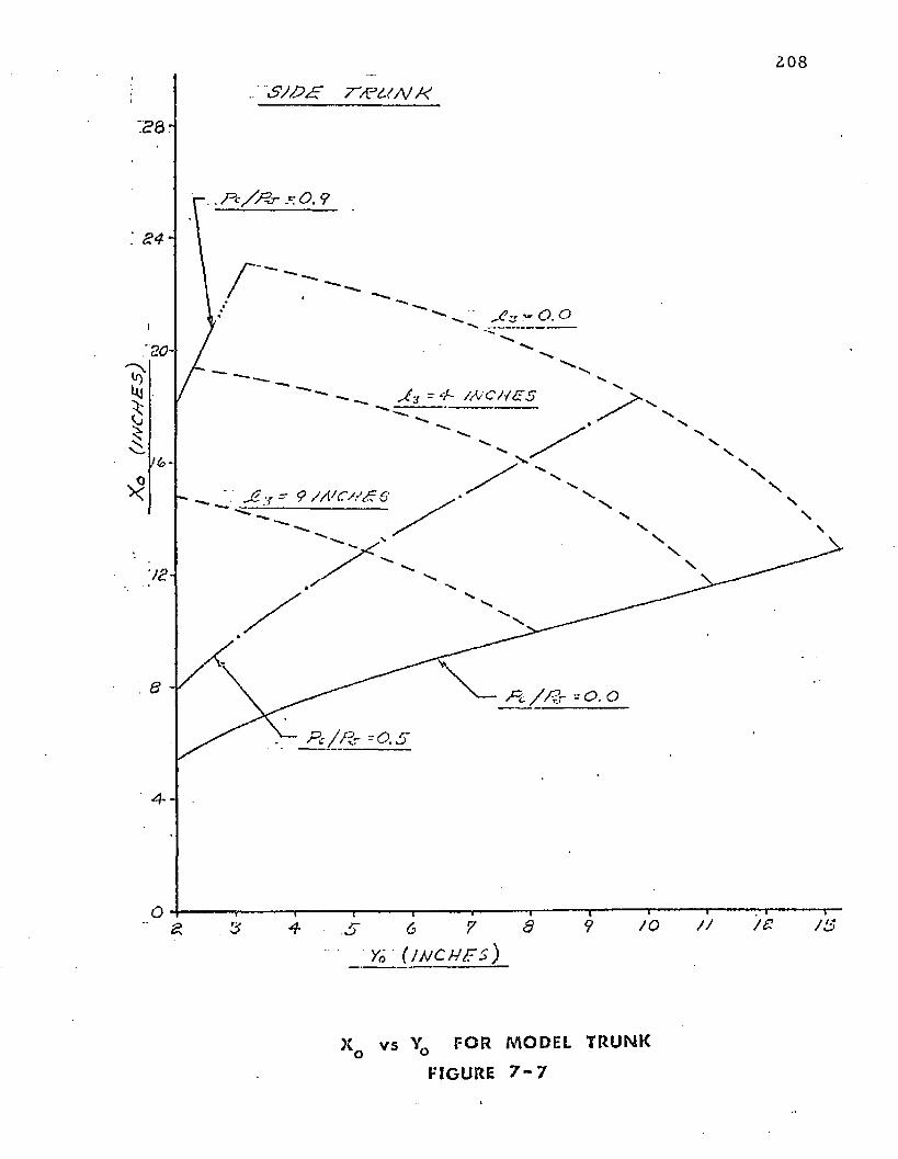
2 0 8
. ~SJ£>£ 77F2^A/ M
J i - 4- / M C H £ 5
Y - ? / A ' C / / £
a 94 6
( J M C H F S )
X v s Yrt F O R M O D E L T R U N K o °
FIGURE 7 - 7
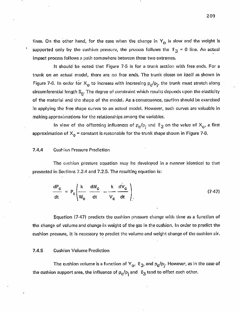
209
lines. On t h e o th e r hand , fo r th e case w hen th e change in Y 0 is s low and th e w e igh t is
su p p o r te d on ly by th e cush ion pressure, th e process fo llow s th e £ 3 = 0 line. An actual
im pac t p rocess fo llow s a pa th so m ew here be tw een these tw o ex trem es .
I t sh o u ld be n o te d th a t Figure 7-5 is fo r a t ru n k section w ith free ends. F o r a
t r u n k on an actual m odel, th e re a re no f ree ends. T h e t ru n k closes o n itself as sh o w n in
c ircum feren tia l length Sg. T h e degree of c o n s tra in t w hich results d ep e n d s u p o n th e e las tic ity
of t h e m ateria l and th e shape o f th e m odel. As a consequence , cau tion shou ld be exercised
in app ly ing th e f ree shape curves t o an actual m odel. However, such curves are va luable in
m aking a p p ro x im a t io n s fo r t h e re la tionsh ips a m o n g th e variables.
In view of th e o ffse tt ing influences o f Pc/p j and fig on th e value o f XQ, a first
a p p ro x im a t io n o f XQ = c o n s ta n t is reasonab le fo r th e t ru n k shape sh o w n in Figure 7-6.
7 .4 .4 Cush ion Pressure P red ic tion
T h e cush ion p ressure e q u a t io n m ay he developed in a m an n e r identical to t h a t
p resen ted in Sec tions 7 .2 .4 and 7 .2 .5 . T h e resulting e q u a t io n is:
E q u a t io n (7-47) p red ic ts t h e cush ion pressure change w ith t im e as a fu n c t io n of
t h e ciiange o f v o lu m e a nd change in w eight o f th e gas in th e cush ion . In o rd e r t o p red ic t th e
cush ion pressure, it is necessary to p red ic t th e vo lu m e and w eight change o f t h e cush ion air.
7 .4 .5 Cushion V o lum e P red ic tion
Figure 7-6. In o rd e r for X Q t o increase w ith increasing pc /p j, th e t ru n k m u st s tre tc h along
dP,
d t
c= P,c (7-47)
T h e cush ion vo lum e is a fu n c t io n of Y Q, £ 3 , a n d pc/p j. H ow ever, as in th e case o f
th e cush ion s u p p o r t area, th e influence of pc /p j and fig te n d to o f fse t each o th e r .
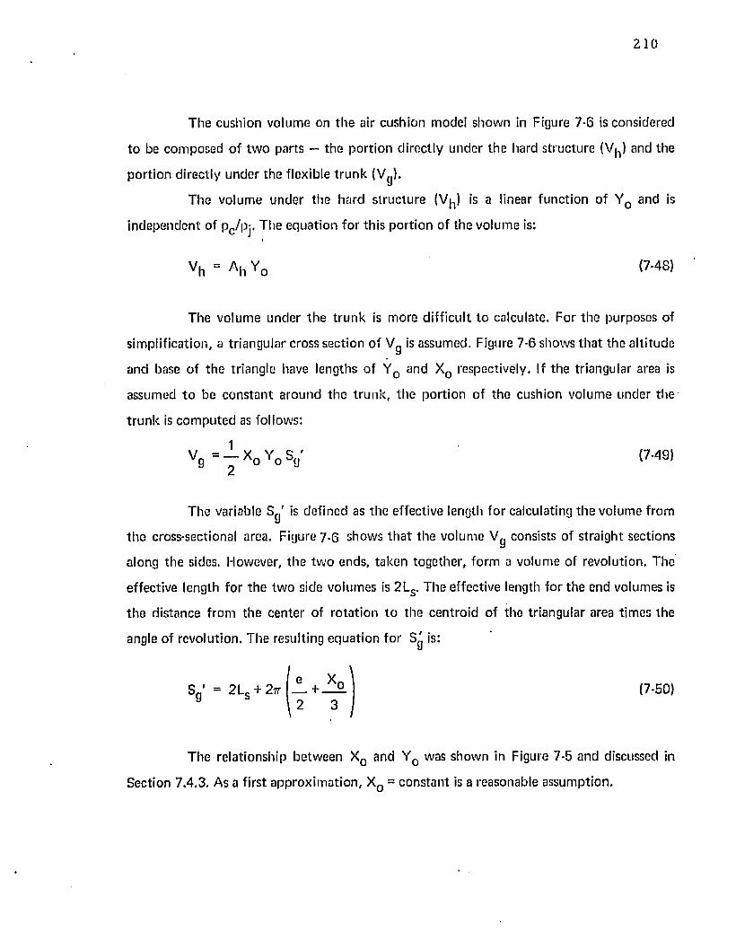
2 1 0
The cushion volume on th e air cushion model shown in Figure 7-6 is considered
t o be com posed of tw o parts — the portion d irectly under the hard structure (V^) and the
po r tion d irectly under the flexible t ru n k ( V g ) .
The volum e under the hard struc tu re (V^) is a linear function of Y 0 and is
independen t of pc/pj. The equation for this portion of the volum e is:
vh = A h Y 0 ( 7 - 4 8 )
The volume under th e t ru n k is more d ifficult to calculate. For the purposes of
simplification, a triangular cross section o f Vg is assumed. Figure 7-6 shows th a t the a ltitude
and base of the triangle have lengths of Y Q and XQ respectively. If th e triangular area is
assumed t o be constan t around the t ru n k , th e portion of the cushion volum e under the
t ru n k is com pu ted as follows:
v g = Y x o Y o s <; I ™ 9 ’
T he variable Sg' is defined as th e effective length fo r calculating th e volume from
th e cross-sectional area. Figure 7-6 shows th a t the volum e Vg consists of s traight sections
along th e sides. However, th e tw o ends, taken together, form a volume of revolution. The
effective length for th e tw o side volumes is 2LS. The effective length for the end volumes is
th e distance from the cen te r of ro ta tion to the centro id of the triangular area tim es the
angle of revolution. T he resulting equa tion fo r Sg is:
\
S g ' = 2 L S + 2 * ( 7 - 5 0 )
The relationship betw een XQ and YQ was shown in Figure 7-5 and discussed in
Section 7.4.3. As a first app rox im ation , XQ = constan t is a reasonable assum ption.
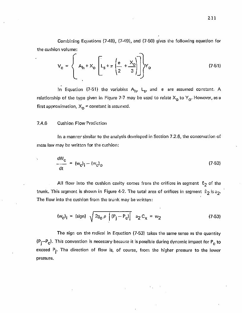
211
Com bining Equations (7-48), (7-49), and (7-50) gives the following equa tion for
t h e cushion volume:
V , = ( A h + X0
1 e + x jLs + 7T
2 3 \ /
>Y, (7-51)
In E quation (7-51) the variables A^, Ls , and e are assumed constan t. A
rela tionship o f th e ty p e given in Figure 7-7 m ay be used t o relate X Q to Y0 . However, as a
f irs t app rox im ation , X 0 = cons tan t is assum ed.
7 .4 .6 Cushion Flow Prediction
In a m an n e r similar t o th e analysis developed in Section 7 .2 .6 , the conservation of
mass law m ay be w ritten for th e cushion:
dWc = (w c )j - (w c )0
d t(7-52)
All f low in to th e cushion cavity com es from the orifices in segm ent C2 of the
t ru n k . Th is segm ent is show n in Figure 4-2. T he to ta l area o f orifices in segm ent >s a 2 -
T he flow in to th e cushion from th e t ru n k m ay be w ritten :
V(wc )j = (sign) -y/ 2 g0 p | (Pj - Pn) a 2 c x = w 5 (7-53)
T he sign on th e radical in E qua tion (7-53) takes th e same sense as th e q u a n ti ty
(Pj—Pc ). This conven tion is necessary because it is possible during dynam ic im pact fo r Pc to
exceed Pj. The d irec tion of flow is, o f course , f rom the higher pressure t o the lower
pressure.
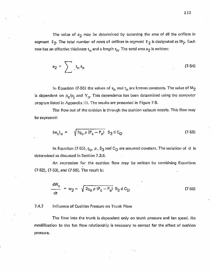
212
The value of 3 3 m aV be de te rm ined by sum m ing the area o f all th e orifices in
segm ent # 2 * The to ta l n u m b er o f rows o f orifices in segm ent 2 2 is designated as M2 . Each
row has an effective th ickness t n and a length sn . The to ta l area a 2 is w ritten :
a 2 = V v n <7 ' 5 4 >
In E quation (7-55) the values o f sn and t n are know n constan ts . T he value of M2
is d e p e n d en t on p c/pj and Y 0 . This dependence has been de te rm ined using th e c o m p u te r
program listed in A ppendix III. T he results are presented in Figure 7-8.
T h e f low o u t of th e cushion is th rough th e cushion exhaust nozzle. This f low m ay
be expressed:
I»C > 0 = i 2% P <pc - pa> s 3 ,J CD <7 ' 5 5 >
In E quation (7-55), g0 , p , S 3 and C q are assum ed cons tan t . T he variation of d is
de te rm ined as discussed in Section 7.3.5.
A n expression fo r th e cushion flow m ay be w ri tten by com bining Equations
(7-52), (7-53), and (7-55). T he result is:
dWc -------------------------- = w 2 - f W 0 P (Pc - Pa > S3 d C D (7-56)
d t
7.4 .7 Influence of Cushion Pressure on T runk Flow
T he f low in to th e t ru n k is d e p e n d e n t only on t ru n k pressure and fan speed. No
m odif ica tion to th e fan f low relationship is necessary t o co rrec t fo r th e effec t o f cushion
pressure.
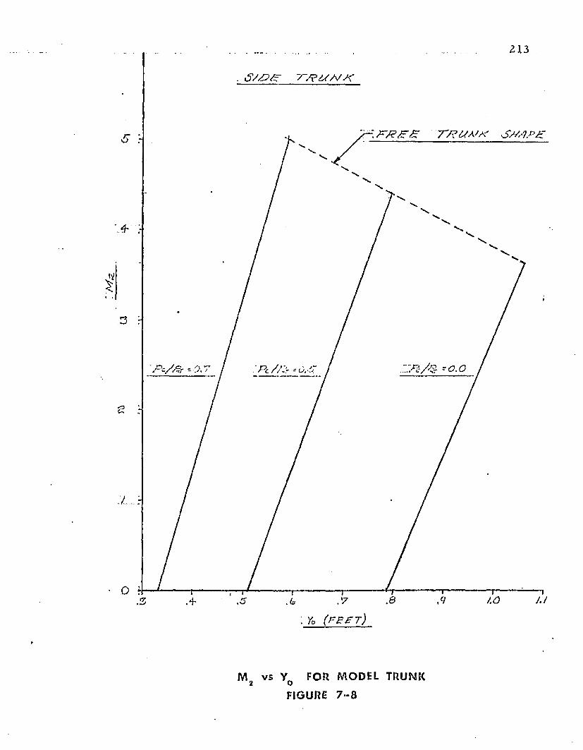
. <5'/Z?< r TTP^/A'A'
rK r / S & g 77? S M '1P £5
I
0
.’7: y0 ( f b z t )
M vs Y FOR MODEL TRUNK2 O
FIGURE 7 - 8
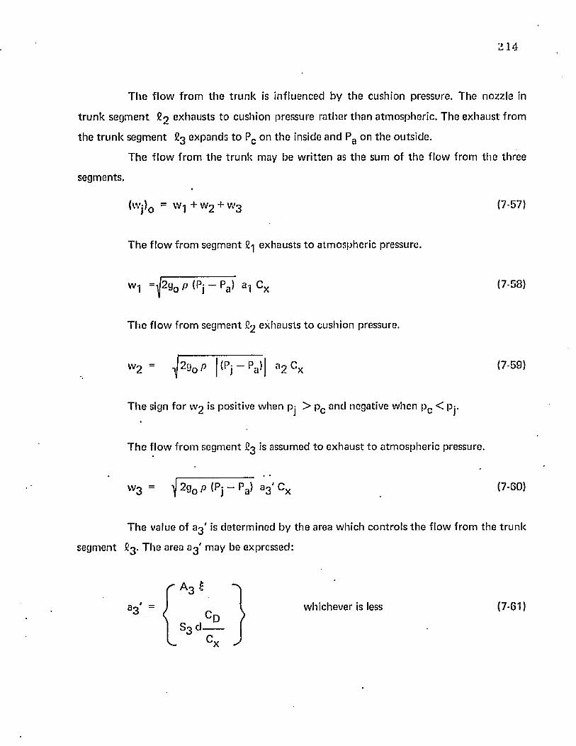
2 1 4
T h e f lo w f ro m t h e t ru n k is in fluenced by th e cushion pressure. T he nozzle in
t r u n k se g m e n t £ 3 exhausts to cush ion p ressure ra the r th a n a tm osphe ric . T he e x h a u s t f rom
th e t r u n k se g m e n t £ 3 expands to Pc on th e inside an d Pa on th e ou ts ide .
T h e f lo w f ro m th e t ru n k m ay be w r i t te n as th e su m of t h e f low from th e th ree
segm ents.
(Wj}Q = w.] + W2 + W3 (7-57)
T h e f lo w f ro m segm en t £•] ex h au sts to a tm o sp h e r ic pressure.
W1 = ^ g 0 p ( P j - P a ) *1 Cx (7-58)
T h e f lo w f ro m se g m e n t £ 2 ex h au sts to cush ion pressure,
w 2 ~ -^2g0 p | (Pj — Pa ) B2 Cx
T h e sign fo r W2 is positive w hen pj > pc and negative w hen pc < Pj.
T h e f low f ro m segm en t £ 3 is assum ed t o e x h a u s t t o a tm o sp h e r ic pressure.
(7-59)
w3 = ^ 2g0 /> (Pj - pa ) a 3 - c x (7-00)
T h e value o f 8 3 ' is de te rm in e d by th e a rea w hich c o n tro ls t h e f low from th e t ru n k
segm en t £3 . T h e area 8 3 ' m ay be expressed:
A 3 £
a V = J I w hichever is less (7-61)* ' C D
S3 d-
2 1 5
In E q u a tio n s (7-58) th ro u g h (7-60) th e in d e p e n d e n t variables a re Pj an d Pc . T he
variables a^ , ag , anc a 3 are d e p e n d e n t on Y Q and pc /p j. T h e value a m ay be d e te rm in e d by
rearranging E q u a tio n (7-38).
a 1 “ aj ” a2 — a3 (7-38)
w here aj is c o n s ta n t .
T h e values of a 2 and a 3 w ere d e te rm in e d in Sec tions 7 .4 .6 and 7 .3 .5 by E qua tions
(7-54) an d (7-37), respectively.
T h e value o f a g ' is d e te rm in e d by th e sam e m e th o d discussed in S ec tion 7 .3 .5 .
7 .4 .8 In fluence o f C ushion Pressure on T ru n k F o o tp r in t Area
T h e in fluence o f pc /p j on t ru n k fo o tp r in t length fo r a side t ru n k sec tion w ith free
edges is s h o w n in Figure 4-21. Fo r th e p c = 0 case, th e re la tionsh ip be tw een f ig and Y Q is
given by t h e pc/p j = 0 curve. Higher values o f pc /p j te n d to decrease f i g fo r a given YQ.
T h e to ta l f o o tp r in t area o f th e m odel sh o w n in Figure 7-6 m ay be c o m p u te d as
th e sum o f th e area o f th e side sec t ions and th e area of th e end sections. T he resulting
e q u a t io n is:
(7-62)
1e 2 f e 1 2
= Ls C3 + 7T — + x o + fi3 — —- + x o2 2
In E q u a t io n (7-62), Ls and e are c o n s ta n ts . As a f irs t a p p ro x im a t io n , XQ is
assum ed c o n s ta n t . T h e va ria tion o f f ig w ith YQ an d p c /p j is given in Figure 4-21.
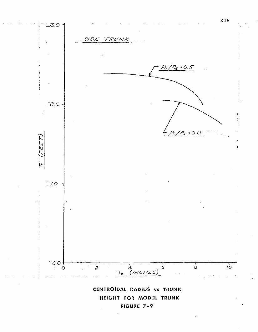
(FO
OT
)
2 1 6
tII
s / o f f f u f f
It
i
:ro.o6 a JOo
■ y0 (/FCH££)
CENTROIDAL RADIUS v s TRUNK
HEIGHT FOR MODEL TRUNK
FIGURE 7 - 9
Z17
7.4 .9 Influence of Cushion Pressure on T runk V olum e
T he influence of pc /pj on t ru n k cross-sectional area fo r a side t ru n k section with
free edges is show n in Figure 4-23. For th e pc = 0 case, th e rela tionship be tw een Aj and Y 0
is given by th e pc/pj = 0 curve. Higher values oT p c/p j ten d to decrease £ 3 fo r a given YQ.
T he to ta l t ru n k volum e is th e p ro d u c t of th e t ru n k cross-sectional area (Aj) and
th e effective t ru n k length (Sj).
T h e effective length for th e tw o sides is 2l_s . T he effective length fo r th e tw o ends
is th e p ro d u c t of th e d istance from th e cen te r o f revolution to the area cen tro id and the
angle of revolution. T he resulting equa tion for the t ru n k volum e is:
Vj “ (2Ls + 2trr~) Aj (7-63)
In E quation (7-63), Ls is cons tan t. The centroidal distance re and the
cross-sectional area Aj are d e p e n d en t on b o th p c/p j and Y Q. T he dependence of these
variables has been show n in Figures 7-9 and 4-23, respectively.
7 .4 .10 Influence of Cushion Pressure on T hrus t
T he presence o f cush ion pressure reduces th e exhaust velocity f rom th e rows of
orifices in the £ 2 segm ent of the t ru n k . The e ffec t of th is reduc tion m ay be app ro x im ated
by ad justing E quation (7-26) to ac co u n t fo r th e cushion pressure across th e £ 3 segm ent.
T he resulting equa tion is:
Fj = [(P j - P c ) a2 + (Pj - Pa ) (aj - a 2 ) Cy ] CX'C Z (7-64)
7.4.11 Sum m ary o f E quations
T he changes required to app ly th e system o f equa tions developed in Section 7 .3
to t h e com ple te air cush ion sys tem have been developed in this section. T h e resulting
eq u a tio n s m ay be sum m arized as follows:
D efin ition of velocity
218
dy .— = y d t
(7-23)
N ew to n 's second law
d V 9p
d t “ WA-W h 3 (Pj + (Pc Pa H' Pj
yo(7-45)
F irs t law of th e rm o d y n am ic s
dP__ J
d t= PJ
k dWj k dVj
W; d t V; d tI i J
(7-43)
dPc
d t " P°
k dWc k d V c
Wc d t Vc d t(7-47)
C onservation of mass law
dW;
d t= p Qj — [w.j + W2 + W3 ] (7-44)
dW„
d t= Wt -
w„2g 0 (Pc - Pa ) S3 d CD
V r(7-56)
G eom etr ic com patib i l i ty
V | = (2LS + 2 tt re ) Aj (7-63)
219
v c - O h + X 0 [Ls + * (•£■ + 0 ) 1 } Y 0 (7-51)
In t h e sy s tem o f e q u a t io n s th e re are e igh t d e p e n d e n t variables: y , y , Pj, Pc , Wj,
Wc , Vj, a n d Vc . T h e fo llow ing variab les a re k n o w n a n d c o n s ta n t : WA , g0 , Pa , k, S3 , C D, Ls ,
A h , X Q, e, Cx , an d C2. .
T h e fo llow ing variables are k n o w n fu n c t io n s o f the d e p e n d e n t variables:
F j = (Pj ~ pc» a 2 + (Pj " Pa> <aj “ a 2 > Cy C x Cz
Y Q = — y f o r y < 0 A s s u m p tio n 7 .3 .1 .7
A c = A h + s g X o
e \ 2 e v \ 2 1= LS H 7T — + x o + *3 “ — + Xo
2 / 2_ / 1
(7-64)
(7-46)
(7-62)
w , = J 2 g 0 W j/Vj ( P j - P a ) a , Cx (7-58)
Wjw 2 = (sign) J2 gQ — - (Pj - Pc ) a 2 Cx
w here t h e sign t a k e s th e sam e sense as t h e q u a n t i ty (Pj — Pc ).
(7-59)
Wjw 3 = J 2 g 0 (Pj - Pa ) a 3 * (7-60)
= f(Pj) as developed in Section 7.4.7.
Cy = f(Y Q) as dev e lo p ed in S ec tion 7 .3 .5 .
a-j = f (Y 0 ,p c /p j) as dev e lo p ed in S e c t io n 7 .4 .7 .
a 2 = « Y 0 . p c / p j ) as deve loped in S ec t io n 7 .4 .7 .
a s ' = f{Y0 , Pc /Pj) as deve loped in S ec t io n 7 .4 .7 .
d = f (Y 0 ) as dev e lo p ed in S e c t io n 7 .4 .7 .
re = f (Y 0 , p c /p j) as dev e lo p ed in S ec tion 7 .4 .9 .
A su ff ic ie n t a m o u n t o f in fo rm a t io n has been deve loped in th is sec t ion t o a l low
th e p red ic t io n o f th e d y n a m ic response o f th e c o m p le te a ir cu sh io n landing sys tem . S uch a
so lu t io n w o u ld req u ire d e v e lo p m e n t o f t h e fu n c t io n a l re la tionsh ips described above for a
p a r t icu la r m odel. T hese re la t ionsh ip s can be deve loped f ro m analy tica l p red ic t io n s by a
p ro c e d u re sim ilar t o t h a t desc r ibed in C h a p te r 8 .
8. EXPERIMENTAL PROGRAM - DYNAMIC MODEL
8.1 Experimental A ppara tus - D ynam ic Tests
Figure 8-1 shows th e tes t appara tus used for verification of th e dynam ic model
developed in Chapter 7. T he appara tus consisted of th ree units — a hydraulic power supply,
a dynam ic model, and a tes t p latform .** * * *
Hydraulic pow er was supplied by a Sun Electric MK-3 A ircraft Hydraulic System
T es t Stand capable of delivering 0 to 3 0 gpm a t variable pressures up to 5 ,000 psig. The
hydraulic power delivered to the dynam ic model was regulated by controlling the flow rate
pressure of the hydraulic fluid which was piped by flexible hoses to th e model.
A drawing of th e dynam ic model is shown in Figure 4-8 and its dimensions are
sum m arized in Table 8-1. T he air source fo r the model was a centrifugal fan powered by a
hydraulic m otor . The fan and m o to r were connected by v-belts. The fan speed was 3.1 times
th e m o to r speed. The m o to r characteristics are shown in Figure 8-2. The fan characteristics
are shown in Figure 8-3. Air was duc ted from the fan in to th e t ru n k and exhausted from the
t ru n k through 1093 holes located in th e vicinity o f the ground plane. The model s truc ture
was fiberglass and the t ru n k was a nylon-hypalon material. The t runk material was
" ine las tic" in th a t it did n o t possess th e 200% to 300% elongation which would be required
fo r com ple te retraction of the t runk . The elastic curve shown in Figure IV-3, A ppendix IV,
is typical fo r the t ru n k material.
T he tes t p la tform was construc ted of wood and was 10 fee t in length by 8 fee t in
width. One section o f th e p lyw ood surface was replaced with plexiglas in order to allow
inspection of the underside of th e tes t m odel. The center of th e p latform contained a 2 ' by
3 ' hole which could be covered with p lyw ood and sealed. The hole in th e cen te r allowed the
cushion pressure to escape and, consequently , th e perform ance of the t ru n k could be
221
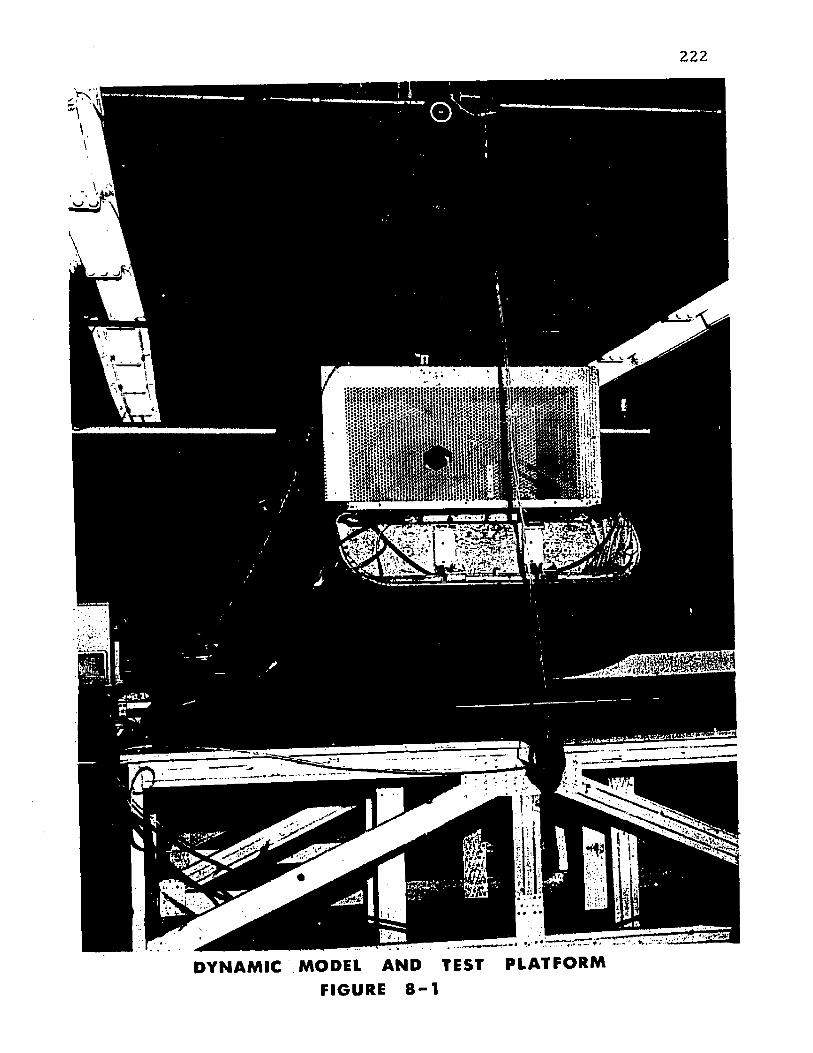
D Y N A M IC MODEL A N D TEST FIGURE 8 - 1
PL A T F O R M
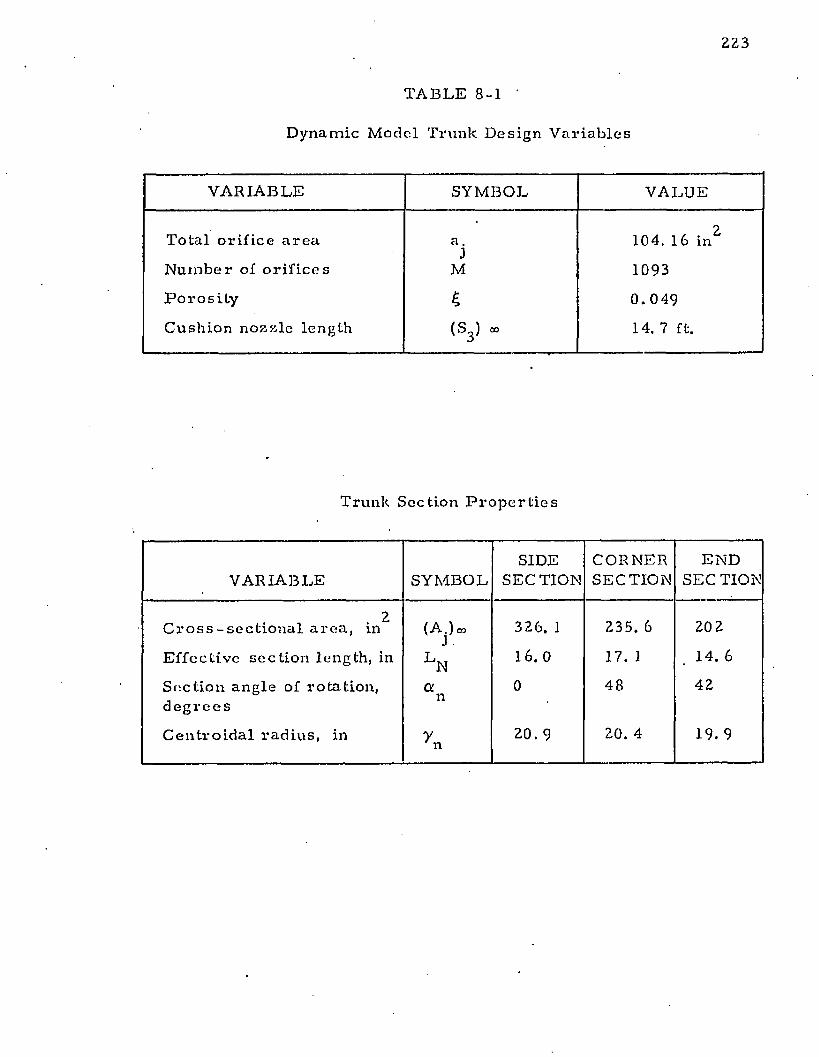
223
TABLE 8-1 '
D y n a m i c M o d e l Tru nk D e s i g n V a r i a b l e s
V A R I A B L E S Y M B O L V A L U E
T o ta l o r i f i c e a r e a
N u m b e r of o r i f i c e s
P o r o s i t y
C u s h i o n n o z z l e l e n g th
a .J
M
£( s 3 J »
104. 16 in 2
1093
0 . 0 4 9
14. 7 ft.
Trunk S e c t i o n P r o p e r t i e s
V A R I A B L E S Y M B O LSIDE
SE C T IO NCOR N ERSE C T IO N
E N D SEC TION
. 2C r o s s - s e c t i o n a l a r e a , in
E f f e c t i v e s e c t i o n len g th , in
S e c t i o n a n g l e of r o ta t io n , d e g r e e s
C e n t r o i d a l r a d i u s , in
(A j ) m
l n
a n
7n
326 . 1
16.0
0
20. 9
235. 6
17. 1
48
20. 4
20 2
14. 6
42
19. 9
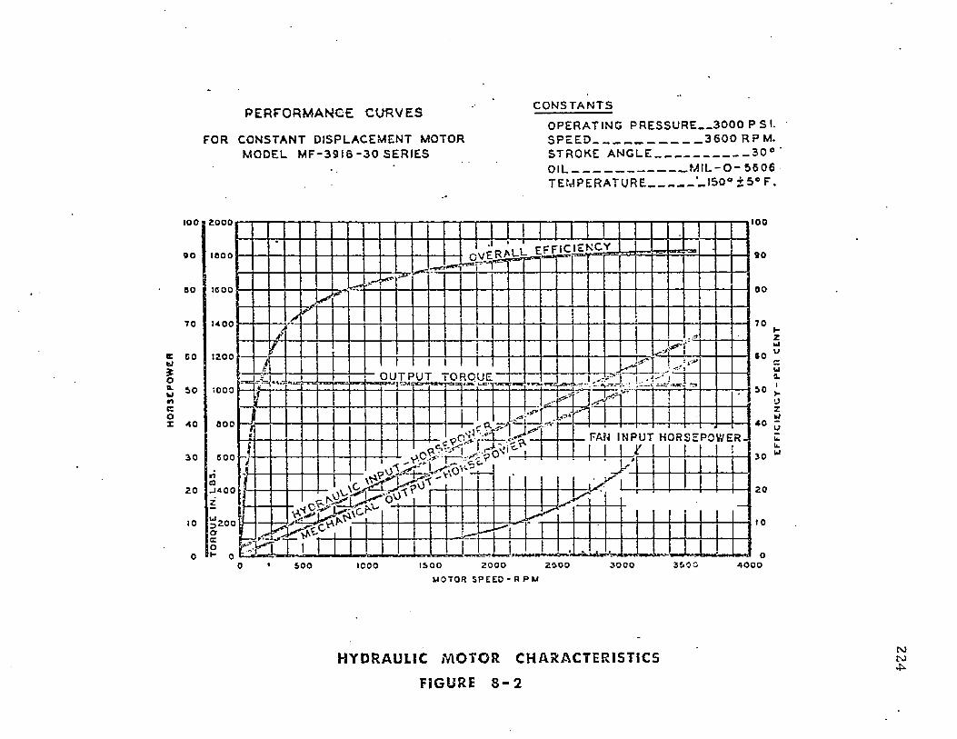
PERFORMANCE CURVES
FOR CONSTANT DISPLACEMENT MOTOR MODEL M F - 3 9 1 6 - 3 0 SERIES
CONSTANTS
OPERATING PRES SURE 3 0 0 0 P S I.S P E E D ___________________ 3 6 0 0 R P M.STROKE A N G L E ________________ 3 0 °Oil_____________________ M I L - 0 - 5 6 0 6T E M PERA TU RE ’_ I S 0 ° ± S « F .
100100B 2000
K n s i S i i s a . 9 0o o I i o o o
00BO teoo
7 07 0 uoo
soc 1200
*o■" 10 M « •)coX 4 0
O U T P U T TORQUEi o o o ——‘i —
0 0 0
FAN I N P U T H O R S E P O W E R, c £ > '303 0 000
2020
u 200
4 0 0 020000 5 0 0 1000MO TOR S P E E D - R P M
H Y D R A U L I C M O T O R C H A R A C T E R I S T I C S
FI GURE 8 - 2
r oro4
EFF
IC
IEN
CY
-
PER
CE
NT
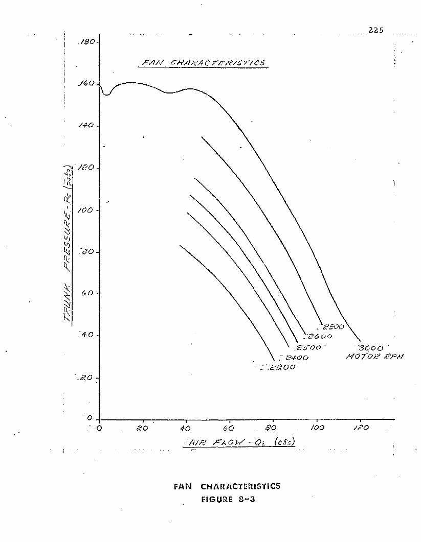
rSrtt
A'A
' /-
/8/A
SS
U^
/f
- A-
fpS
225i
II A ' / ) / / <?/?/} C T / C S!
I
/G O -
:8o-
4 0 -
3000 / 4 0 .T O /3 /? /> //
80O 60
A J /8 / ^ A O I S - Q } . ( c S s )
FAN CHARACTERISTICS
FIGURE 8 - 3
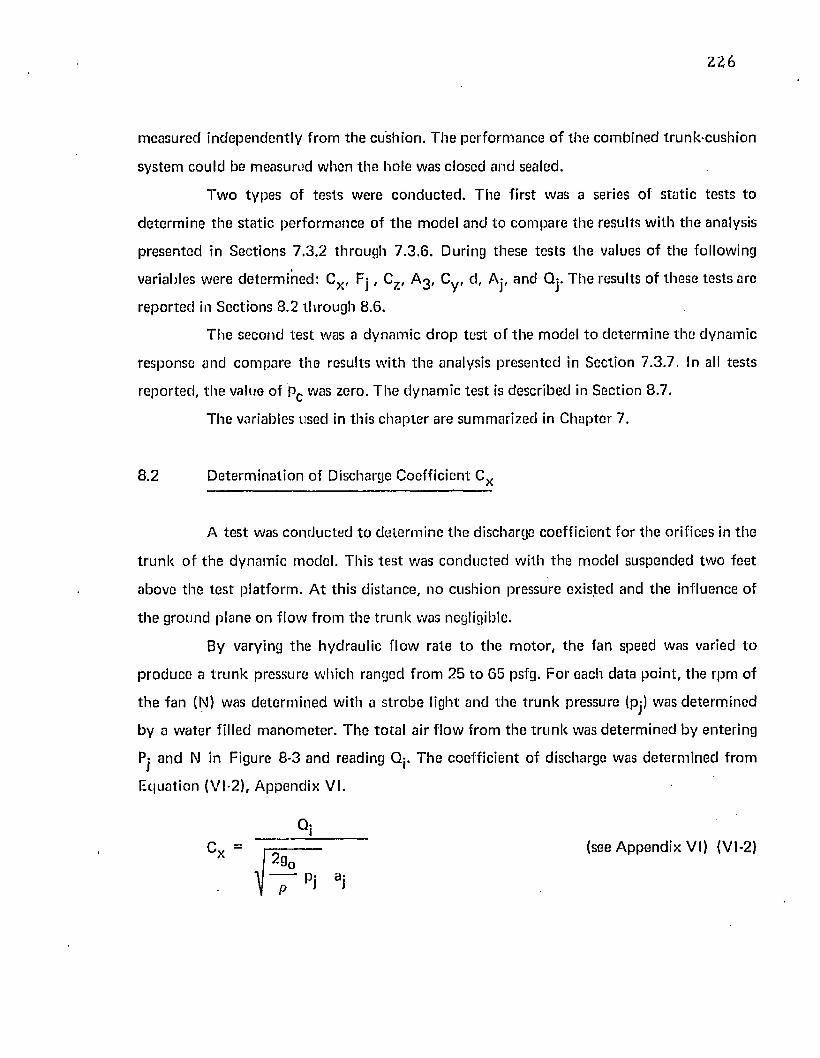
Z26
m easured independen tly from th e cushion. T he perfo rm ance o f the com bined trunk-cush ion
system could be m easured w hen the hole was closed and sealed.
T w o types of tes ts were c o nduc ted . The first was a series of s ta tic tes ts to
de te rm ine th e s ta t ic pe rfo rm ance of th e model and to com pare th e results w ith th e analysis
presen ted in Sections 7 .3 .2 th rough 7 .3 .6 . During these tes ts the values o f the following
variables w ere de te rm ined : C x , F j , Cz , A 3 , Cy, d, Aj, and Qj. T he results of these tests are
reported in Sections 8.2 th rough 8.6.
T he second tes t was a dynam ic d ro p tes t o f the model to de te rm ine the dynam ic
response and com pare th e results w ith the analysis presented in Section 7.3.7. In all tests
reported , th e value of Pc was zero. T he dynam ic tes t is described in Section 8.7.
T he variables used in this chap te r are sum m arized in Chapter 7.
8.2 D eterm ination of Discharge Coefficient Cx
A tes t was con d u c ted to de te rm ine th e discharge coeffic ien t for the orifices in the
t ru n k o f th e dynam ic m odel. This te s t was conduc ted with the model suspended tw o feet
above the te s t p la tfo rm . A t th is distance, no cushion pressure existed and the influence of
th e ground plane on f low from the t ru n k was negligible.
By varying the hydraulic f low rate to the m o to r , th e fan speed was varied to
p roduce a t ru n k pressure w hich ranged from 25 to 65 psfg. For each data po in t, th e rpm of
th e fan (N) was de te rm ined w ith a s tro b e light and th e t ru n k pressure (pj) was de te rm ined
by a w ater filled m anom ete r . T he to ta l air f low from th e t ru n k was de te rm ined by entering
Pj and N in Figure 8 - 3 and reading Q j. The coeffic ien t of discharge was de te rm ined from
E quation (VI-2), A ppendix VI.
QiCx = n “ ------ (see Appendix VI) (VI-2)
2g0Pj aj
"C£
227
.1' Cx ~ 0.6 64
O. Cs.
; 0.5 -
0.990.980.96i
i * - ■
T R U N K D I S C H A R G E COEFFI CI ENT v s P / P ,A J
FIGURE 8 - 4
228
O' F /K 6 T &UMte ' S t'C O /'/'O / ? « / • /0 . T H / K P
.14.0-
10.0 -
NJ
so.o3 0 .0/ t r (p>s S q)
THRUST v s T R UN K PRESSURE
FIGURE 8 - 5
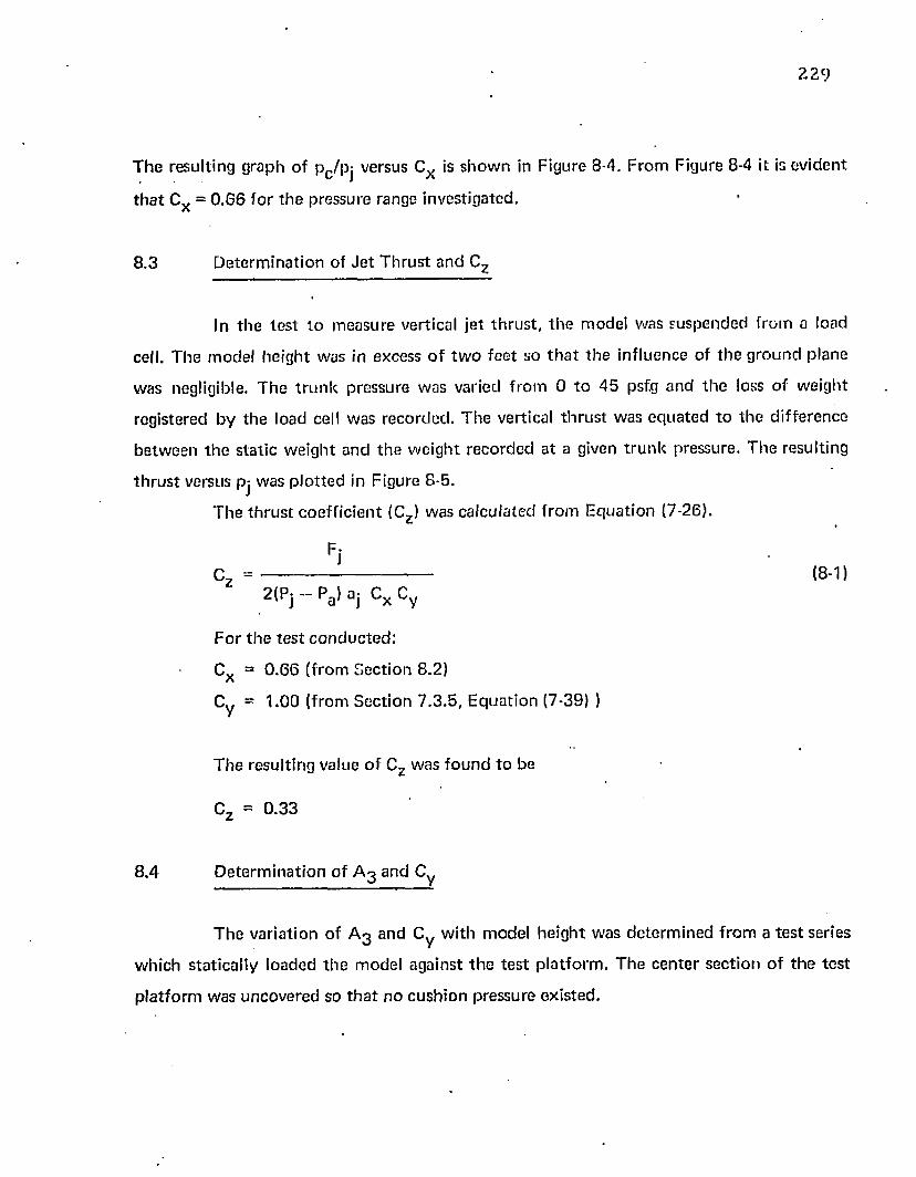
2 2 9
T h e resu lting g raph o f p c /pj versus Cx is s h o w n in F igure 8-4. F ro m Figure 8-4 it is ev id en t
t h a t Cx = 0 .6 6 fo r t h e p ressure range inves tiga ted .
8 .3 D e te rm in a t io n o f J e t T h ru s t an d Cz
In th e t e s t t o m easu re vertical je t th ru s t , t h e m odel w as su sp en d ed f ro m a load
cell. T h e m o d e l h e ig h t was in excess o f t w o f e e t so t h a t t h e in f luence of t h e g ro u n d p lane
w as negligible. T h e t r u n k p ressu re w as varied f ro m 0 t o 4 5 psfg a n d th e loss o f w e igh t
reg is tered b y th e load cell w as rec o rd e d . T h e vertical t h r u s t w as e q u a te d to th e d if fe re n c e
b e tw e en t h e s ta t ic w e ig h t an d th e w e ig h t r ec o rd e d a t a given t r u n k p ressure . T h e resu lting
t h r u s t versus pj w as p lo t t e d in F igure 8-5.
T h e t h r u s t c o e f f ic ie n t (Cz ) w as c a lcu la ted f ro m E q u a t io n (7-26).
FiCz ---------- — ------------ ■— (8-1)
2 ( Pj - Pa ) a , C x Cy
F o r t h e t e s t c o n d u c te d :
Cx = 0 .6 6 ( f rom S e c t io n 8 .2)
Cy = 1 .00 ( f ro m S e c t io n 7 .3 .5 , E q u a t io n (7-39) )
T h e resu l ting value o f Cz w as fo u n d to be
Cz = 0 .3 3
8 .4 D e te rm in a t io n o f A 3 a n d Cy
T h e va r ia t ion o f A 3 an d C y w ith m odel h e ig h t w as d e te rm in e d f ro m a t e s t series
w h ich s ta t ica lly lo ad ed th e m odel aga ins t t h e te s t p la t fo rm . T h e c e n te r s e c t io n o f t h e t e s t
p la t fo rm was u n c o v e re d so t h a t n o c u sh io n p ressu re ex is ted .
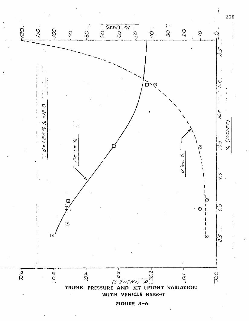
>0 o
T R U N K P R ESSURE A N D JET H E I GH T V A R I A T I O N
W I T H VEHICLE HEI GHT
FIGURE 8 - 6
2 3 1
A DA777 DO/NT:ao -
J3
■p ADD'D/M PN D Pa/Dr - O. O
PAED/CTD Do. o
/ £2 JO4-
SYo ( /NCHDS)
F OO TP RI NT AREA v s VEHICLE HEI GHT
FIGURE 3 - 7
23 2
T h e fan speed w as m ain ta in e d a t a c o n s ta n t rp m and th e w e igh t s u p p o r te d by th e
t r u n k was varied. F o r low t r u n k toads, th e m odel w as pa rt ia l ly su sp en d e d f rom a load cell.
T h e load o n th e t r u n k was d e te rm in e d b y th e loss o f w e igh t registered by th e load cell. For
heav ier loads, th e m odel was loaded w ith k n o w n q u a n t i t ie s o f lead w eights .
loca t ion o f w eigh ts an d t h e fan speed was set a t 8 0 0 0 rpm . T h e t r u n k he ig h t (Y Q) was
m easu red w ith a scale an d th e je t he igh t (d) was m easu red by rods of c a lib ra ted th ickness .
T h e t r u n k p ressure was m easu red by a w a te r tu b e m a n o m e te r .
T h e re c o rd e d values o f je t h e ig h t (d) an d t ru n k pressure (pj) a t a c o n s ta n t fan
speed of 8 0 0 0 rpm are s h o w n in Figure 8-6.
T h e effec tive f o o tp r in t a reas of t h e t r u n k w ere ca lcu la ted f ro m th e w eigh t
s u p p o r te d an d th e t r u n k pressure.
T h e resu lting e x p e r im e n ta l ly d e te rm in e d values o f Ag versus Y0 are sh o w n in F igure 8-7.
T h e values o f Ag ca lcu la ted b y th e c o m p u te r p ro g ram deve loped in S ec tion 4 .5
w ere a lso p lo t t e d in F igure 8-7. V alues o f Ag w ere c o m p u te d f ro m th e values o f Cg s h o w n
in F igures 4-21 a n d 4 -22 using te c h n iq u e s descr ibed in S ec tions 7 .3 .3 a n d 7 .4 .8 . In
c o m p u t in g Ag, t h e t r u n k was d iv ided in to th re e p a r ts — th e ends, th e sides, and th e co rners .
T hese th r e e pa r ts a re d es igna ted b y Le, Ls , a n d respectively (see F igure 4-8). T h e
respec tive f o o tp r in t a reas w ere c o m p u te d as fo llows.
D ata was re c o rd e d a t a p p ro x im a te ly 1 -inch in c re m e n ts over a m odel h e ig h t range
f ro m 11 inches t o 7 inches. A t each d a ta p o in t , th e m odel w as leveled by ad jus t ing th e
(8-2 )
Pi
(Ag)s - (fig)s Ls (8-3)
{A3>e "<«>e
2(8-4)
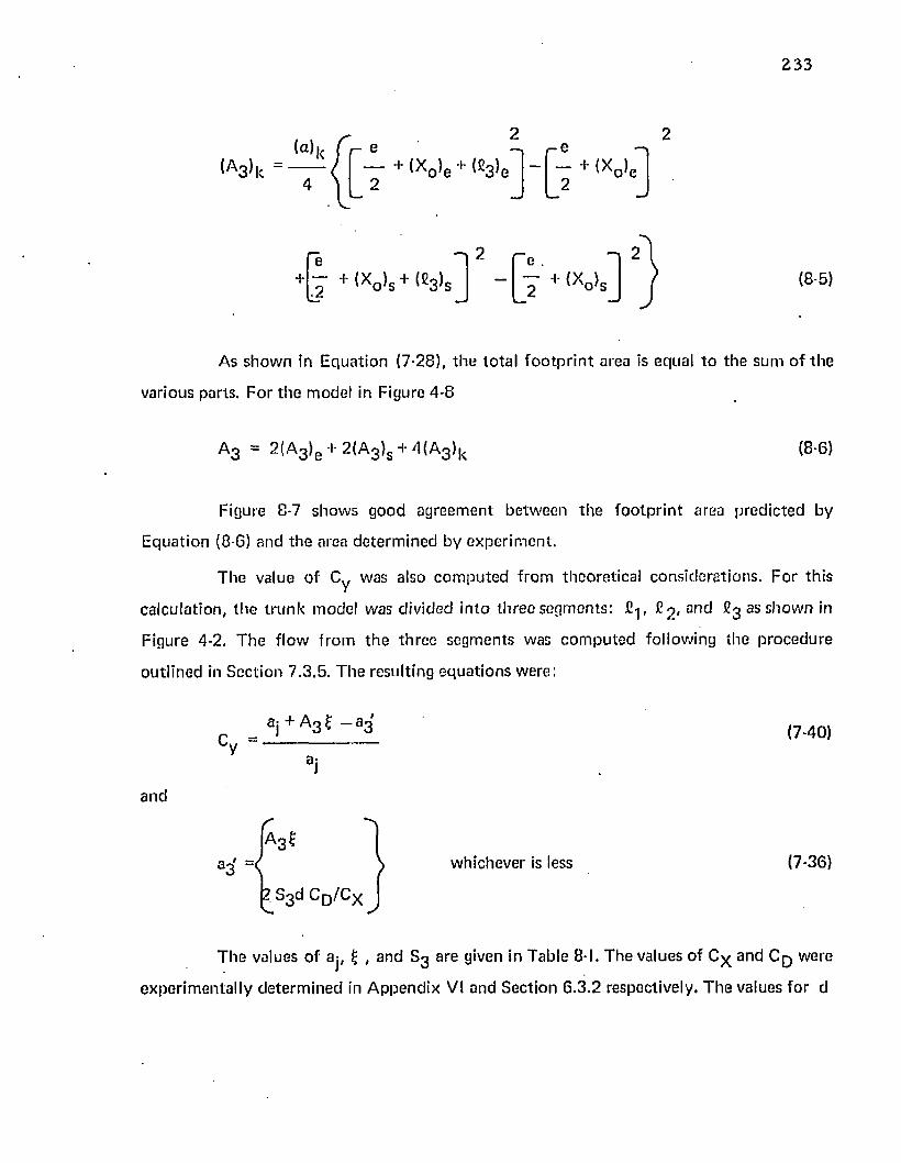
As sh o w n in E qua tion (7-28), th e to ta l f o o tp r in t area is equal t o th e sum o f th e
various parts. F o r th e m odel in Figure 4-8
a 3 “ 2 ^A 3^e + 2 (A 3>s + 4 *A 3*k (8 -6 )
Figure 8-7 show s good agreem ent be tw een th e fo o tp r in t area p red ic ted by
E qua tion (8 -6 ) and th e area d e te rm in e d by ex p e r im en t .
T he value o f Cy was also c o m p u te d f rom theore tica l cons idera tions . F o r th is
ca lcu la tion , th e t ru n k m odel was divided in to th re e segm ents: fi-j, anc* ^ 3 as show n in
Figure 4-2. T h e f low f ro m th e th ree segm en ts was c o m p u te d following th e p rocedu re
ou tlined in S ec tion 7 .3 .5 . T he resulting eq u a tio n s were:
aj + a 3 £ - a 3'(7-40)
and
A 3*
S3 d C D/C X
whichever is less (7-36)
T h e values o f aj, f- , and S 3 are given in Table 8-1. T he values of Cx and C q were
expe r im en ta l ly d e te rm in e d in A p p en d ix VI and Sec tion 6 .3 .2 respectively. T h e values fo r d
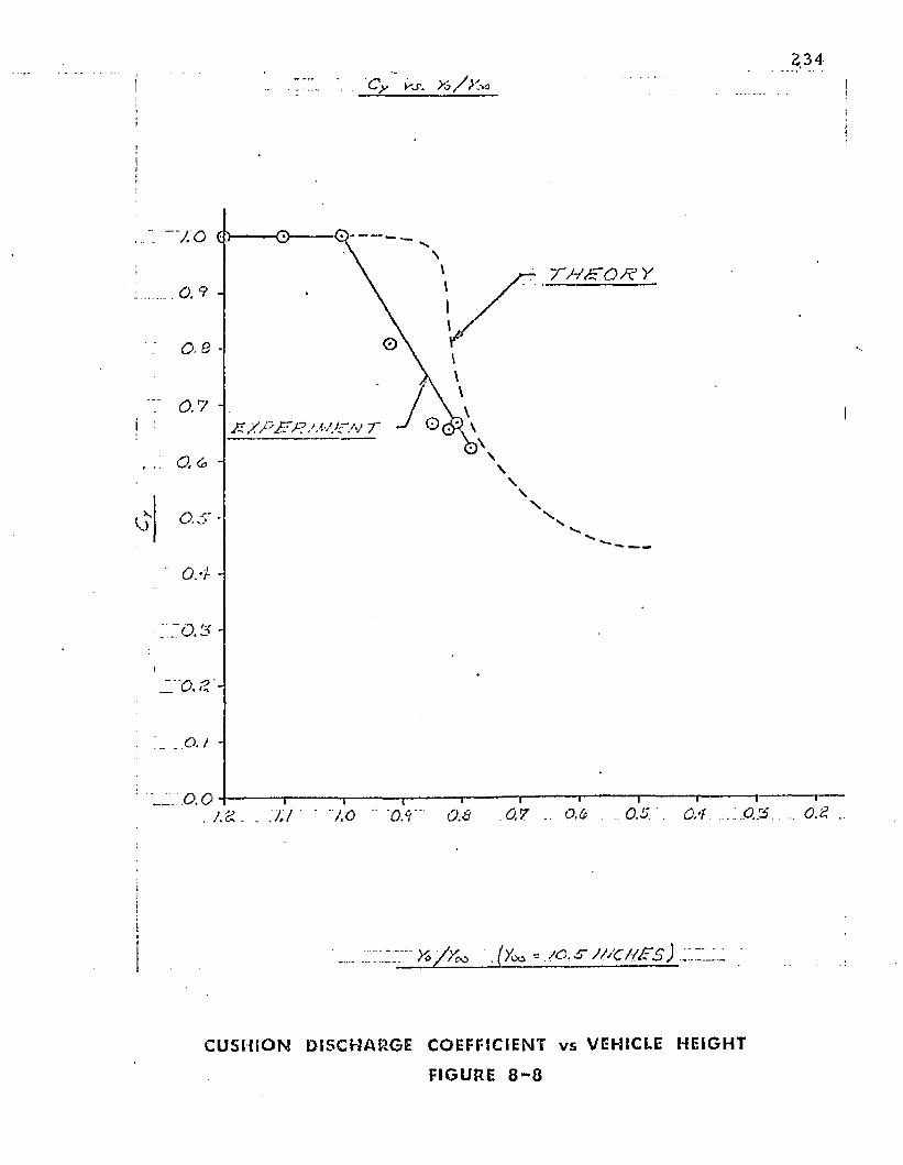
7 0 C>
0.7 -i z / p z - j? > r/ ' i r
0.4 -
o./
.0. 0 + - . J.d 0.5.0.7 0 , ‘fKI 7.0
..... r* / / M . (y^ -oo.s- ///c//jrs) ;
C U S H I O N DI S C H A R G E COEFFICIENT v s VEHICLE HEIGHT
FIGURE 8 - 8
2 3 5
a n d A 3 versus Y 0 are given in Figures 8 - 6 an d 8-7 respectively . T h e resulting varia tion o f Cy
w ith Y Q is given in Figure 8 -8 .
8 .5 D e te rm in a t io n o f T ru n k V olum e
A te s t was c o n d u c te d to d e te rm in e th e varia tion in t ru n k vo lum e w ith m odel
height.
T h e t ru n k vo lum e in t h e free (un loaded) c o n d it io n was de te rm in e d by graphical
in te g ra t io n o f th e various cross-sectional areas show n in Figure 4-8. T he to ta l t r u n k vo lum e
was fo u n d t o be 2 5 .2 4 f t^ . T he vo lum e o f th e d u c t in g be tw een th e fan an d t ru n k was 1.8
f t 3
T h e change in vo lum e w ith m odel he igh t was de te rm in e d from th e change in
t ru n k cross-sectional area as th e m odel was s ta t ica lly loaded against th e te s t p la t fo rm .
A c o n s ta n t fan speed of 8 ,0 0 0 rpm was used fo r th is test. T h e f loo r c e n te r
sec tions w ere rem oved to p reven t cushion p ressure bu ild -up and t o a llow access to th e inside
po r tio n o f t h e t ru n k . T h e m odel he igh t was varied by changing th e load w hich was
s u p p o r te d by th e t ru n k . Data p o in ts w ere tak e n a t a p p ro x im a te ly every 1.5 inches f rom a
m odel he igh t of 12 inches d o w n to 6 .25 inches. T h e t ru n k shape was d e te rm in ed a t th e
m id p o in t o f one side and o n e end for each d a ta po in t.
T h e g round ta n g e n t po in ts , (x-j, y 0 ) and (x2 , y D) in Figure 4-2, w ere de te rm in e d
by m easuring th e vertical and ho r izon ta l d is tance relative to th e a t ta c h m e n t p o in ts (o, o)
an d (a, b).
T h e c o n to u r be tw een an a t ta c h m e n t p o in t and a g round ta n g e n t p o in t was
d e te rm in e d by f i t t in g a co p p e r w ire against t h e t ru n k . T h e co p p e r wire was d e fo rm ed
plastically to re ta in t h e t ru n k c o n to u r . T he inside and o u ts ide c o n to u rs ( £ 2 and C-j in
Figure 4-2, respectively) w ere t ransfe rred b y th e c o p p e r w ire t o a full scale d raw ing o f th e
t ru n k cross sec t ion . T h e resulting areas w ere m easured w ith a com pensa ting po lar
plani m eter.
2 3 6
T h e vo lum e o f th e t ru n k was ca lcu la ted f ro m th e side an d en d cross-sectional
areas in a m a n n e r s im ilar t o th a t o u t l in ed in Sec tion 7 .3 .4 . In o rd e r to p e rfo rm this
ca lcu la t io n , t h e t ru n k vo lum e was separa ted in to th e fo u r pa rts — th e end shape, th e co rner
shape, t h e s ide shape, a n d th e fan duc ting . These parts are show n in Figure 4-8. It is ev iden t
f ro m th e f igu re t h a t th e to ta l vo lum e o f th e t ru n k is
V j = 2 V e + 2 V s + 4 V R + V f (8 -1 0 )
T h e vo lu m e o f th e en d is a vo lum e o f revo lu tion . T h e rad ius vec to r be tw e en the
c e n te r o f rev o lu t io n and th e c e n tro id of th e cross-sectional area is r0 . T h e to ta l vo lum e of
t h e tw o e n d sec tions is th e p ro d u c t of th e angle of revo lu t ion , th e radius and th e
cross-sectional area. T h e resu lt is:
V e = a e 'o IAjlc ( S H I
T h e vo lum e o f th e tw o sides is th e p ro d u c t of the sec tion length Lg and th e
cross-sectional area. T h e resu lt is:
Vs = L s (Aj)s . (8-12)
T h e vo lu m e of a co rn e r sec tion is m ore d iff icu l t to ca lcu la te th a n th e o th e r
volum es. I t ap p ro a c h e s a vo lum e of ro ta t io n , how ever th e cross-sectional area and th e radius
o f th e c e n t r o id vary w ith t h e angle of ro ta t io n . O n o n e side th e cross-sectional area is ( A j ) e
and th e c e n t ro id radius is re . O n t h e o th e r side th e cross-sectional area is ( A j ) s and th e
cen tro id a l rad ius is rs . It is ev iden t th a t th e vo lum e o f a single co rner sec t ion lies in th e range
a e ^ ( A j > e < V k < a s 7s <Aj)s _ (8-13)

237
m ade.
In o rd e r t o a p p ro x im a te th e c o rn e r vo lum e, th e fo llow ing a ssum ptions w ere
(1) T h e effective cen tro ida l radius fo r th e co rner section is th e average of
th e end and side radii.
re + rsri, =- (8-14)
(2) T h e values of re and rs do n o t change with Y n .
(3) T h e effective cross-sectional area o f th e co rn e r sec tion lies som ew here
be tw een (Aj)e and (Aj)s,
(Aj)k = (Aj)s +(1 (Aj)e (8-15)
w here f is a f rac tio n be tw een 0 .0 and 1.0.
T h e resu lting co rn e r vo lum e is:
v k ” a k-<re + rs»
f (Aj)s +(1 - f ) (Ai 'e ] (8-16)
T h e to ta l t r u n k vo lum e m ay n o w be w ri t te n :
Vj = 2 r a e re (Aj) J + 2 f l S *Aj*s
+ 4 ( ai<re - V
0 (A|>0 + jr (Aj)s + V.
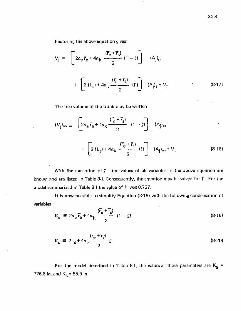
2 3 8
F ac to r in g th e above e q u a t io n gives:
0v j = | 2 a e re + 4 a kre + rs^
(1 - ? ) ( A j ) e
0(re + rs>
+ | 2 ( I . J + 4 a , , -----------------(?)ii l\ (Aj)s + V f (8-17)
T h e free vo lu m e o f t h e t r u n k m ay be w r i t te n
■ [■ (rc + rs }(VjJoo _ | 2 a e re + Aak --------------- ( 1 - ? ) (Af)oo
[»<re + rs^
+ I 2 (Ls) + 4 a k ------------- (?) ( A j ) o o + V f (8-18)
W ith t h e e x c e p t io n o f ? , t h e values o f all variables in th e above e q u a t io n are
k n o w n a n d are listed in T ab le 8-I. C o n se q u e n tly , t h e e q u a t io n m ay be solved fo r ? . F o r th e
m odel su m m a riz e d in T a b le 8-I th e value o f ? w as 0 .7 2 7 .
ft is n o w possib le t o s im plify E q u a t io n (8-18) w ith th e fo llow ing c o n d e n sa t io n o f
variables: '
Ke - 2 a e re + 4 a k(re + rs)
(1 - ? ) (8-19)
K s = 2 L s + 4 a k<re + rs>
(8-20)
F o r t h e m odel descr ibed in T a b le 8-I, t h e values o f th ese p a ra m e te rs a re Kg =
126 .6 in. a n d Ks = 5 5 .5 in.
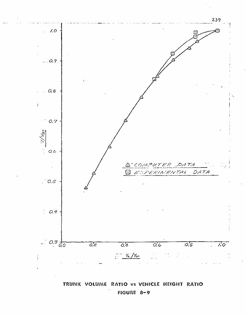
239
0 ,6
77-V __ _
□ ' t> ? / £>/7 7>?
o ! s 0.30 .4
' ' Vo /Vc*
T R UN K VOLUME R AT I O v s VEHICLE HEI GHT RATIO
FIGURE 8 - 9
2 4 0
T he general e q u a t io n fo r th e to ta l vo lum e of th e t ru n k and d uc ting m ay be
w ri t ten
Vj = K„ (Aj)0 + Ks (Aj)s + Vf (8-21)
T h e vo lum e ra tio is
Kb (Aj)e + Ks (Aj}s + Vf
( v j j ^(8-22 )
Figure 8-9 show s th e values of V j / ( V j ) co c o m p u te d f rom th e experim en ta lly
d e te rm in e d values o f (Aj)e and (Aj)s . In a d d it ion , th e values of Vj/Vj ^ c o m p u t e d f rom th e
c o m p u te d values o f (Aj)s and (Aj)e versus V 0 /V ^ a r e show n in Figures 4-23 and 4-24.
T h e fan charac te r is t ics were de te rm in e d b y m easuring th e f low f rom th e fan a t
various speeds and back pressures.
In th e ca lib ra t ion tes ts , t h e fan and d u c ting w ere installed above a p lyw ood
p lenum ch a m b e r o f a p p ro x im a te ly th e sam e vo lum e as th e free vo lum e o f th e t ru n k . T w o
convergen t conical nozzles w ith an included angle o f 12 degrees w ere installed on o p pos ite
sides of th e p lenum . T he discharge coeff ic ien t o f th e conical nozzles was c o n s ta n t a t 0 .9 5
over th e range o f R eynolds num bers o f in te res t in th e tes t . Data was reco rded a t 2 0 0 rpm
increm en ts , a t m o to r speeds ranging be tw een 2 2 0 0 rpm and 3 0 0 0 rpm . T he back pressure
( tru n k pressure) was varied by changing th e e x i t area o f th e convergen t nozzles. Since th e
coeff ic ien ts fo r t h e nozzles were k now n , th e to ta l f lo w f ro m th e fan could be ca lcu la ted
f ro m th e fo rm u la given in A p p en d ix VI.
values o f A: p red ic ted by th e c o m p u te r p rogram developed in C hap te r 4 are show n. The
8.6 Fan Characteris tics
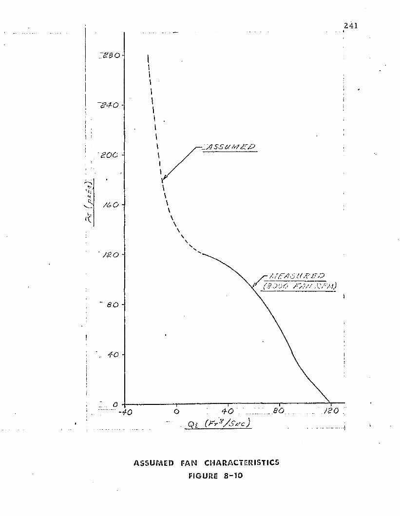
241
ii
1i
Ii a o o -
/ & o -
J Z O -
Ai/T/16 iO?JTO
" 80 -
tt
i
j a o :■80
A S S U M E D F AN CHARACTERI STI CS
FIGURE 8 - 1 0
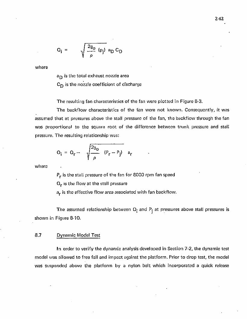
2 4 2
Q j = — (Pj> a D C D
w h e re
is th e to ta l e x h a u s t nozz le area
C p is t h e nozz le c o e ff ic ie n t o f d ischarge
T h e resu lting fan cha rac te r is t ic s o f th e fan w ere p lo t te d in F igure 8-3.
T h e b a c k f lo w c h a rac te r is t ic s o f th e fan w ere n o t k n o w n . C o n se q u e n tly , it was
a ssum ed t h a t a t p ressures above th e stall p ressu re o f th e fan , th e b a c k f lo w th ro u g h th e fan
w as p ro p o r t io n a l t o th e sq u a re ro o t o f t h e d iffe rence b e tw e e n t r u n k p ressure a n d stall
p ressure. T h e resu lting re la t ionsh ip was:
Qj - Q r — J (Pr - Pj) a r
w h ere
Pr is t h e stall p ressu re o f th e fan fo r 8 0 0 0 rpm fan speed
Q r is th e f lo w a t th e stall p ressure
a r is t h e e ffec tive f lo w area assoc ia ted w i th fan back flow .
T h e a ssu m ed re la t io n sh ip b e tw e e n Q; a n d Pj a t p ressures above stall p ressu res is
s h o w n in F igure 8-10.
8 .7 D y n a m ic M odel T es t
In o rd e r t o verify t h e d y n a m ic analysis deve loped in S ec tion 7-2 , th e d y n a m ic te s t
m odel w as a llow ed t o f ree fall an d im p a c t aga ins t t h e p la t fo rm . P rior t o d r o p tes t , th e m odel
w as s u s p e n d e d above t h e p la t fo rm by a n y lo n b e l t w h ich in c o rp o ra te d a q u ick release
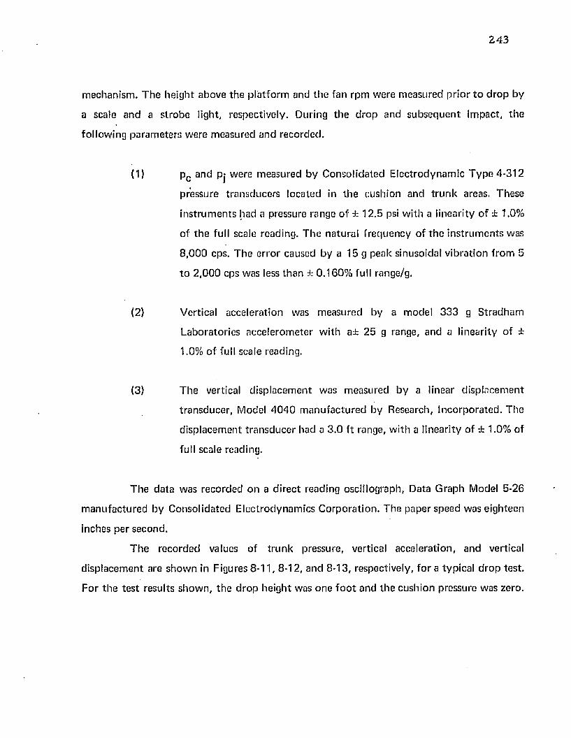
24 3
m echanism . T h e he igh t above th e p la t fo rm and th e fan rp m w ere m easured p r io r t o d ro p by
a scale and a s trobe light, respectively . During th e d ro p an d su b seq u e n t im pac t, th e
fo llow ing pa ram ete rs w ere m easu red and reco rded .
(1) pc and pj w ere m easured by C onso lida ted E lec trodynam ic T y p e 4 -312
pressure tran sducers loca ted in th e cushion and t ru n k areas. These
in s t ru m e n ts had a pressure range o f ± 12 .5 psi w ith a linearity o f -Jt 1.0%
of th e full scale reading. T h e na tu ra l f requency o f th e in s t ru m e n ts was
8 ,0 0 0 cps. T he e rro r caused by a 15 g peak sinusoidal v ib ra tion f ro m 5
t o 2 ,0 0 0 cps was less th an ± 0 .160% full range/g.
(2) Vertical acce lera tion was m easu red by a m odel 3 3 3 g S tradham
L aborato ries acce le ro m ete r w ith a± 25 g range, and a l inearity of ±
1.0% of full scale reading.
(3) T he vertical d isp lacem en t was m easu red by a linear d isp lacem en t
tran sd u cer , Model 4 0 4 0 m a n u fa c tu re d by Research, In co rp o ra ted . T he
d isp lacem en t t ra n sd u c e r had a 3 .0 f t range, w ith a l inearity of ± 1.0% of
full scale reading.
T h e d a ta was reco rded on a d irec t reading oscillograph, Data G raph Model 5-26
m an u fa c tu red by C onso lida ted E lec trodynam ics C o rp o ra t io n . T he paper speed was e ighteen
inches pe r second .
T h e reco rded values of t ru n k pressure, vertical accelera tion , and vertical
d isp lacem en t are s h o w n in Figures 8 -11 , 8-12, an d 8-13, respectively, fo r a typ ica l d ro p tes t .
F o r t h e te s t results sh o w n , th e d ro p he igh t was o n e f o o t and th e cush ion pressure was zero .
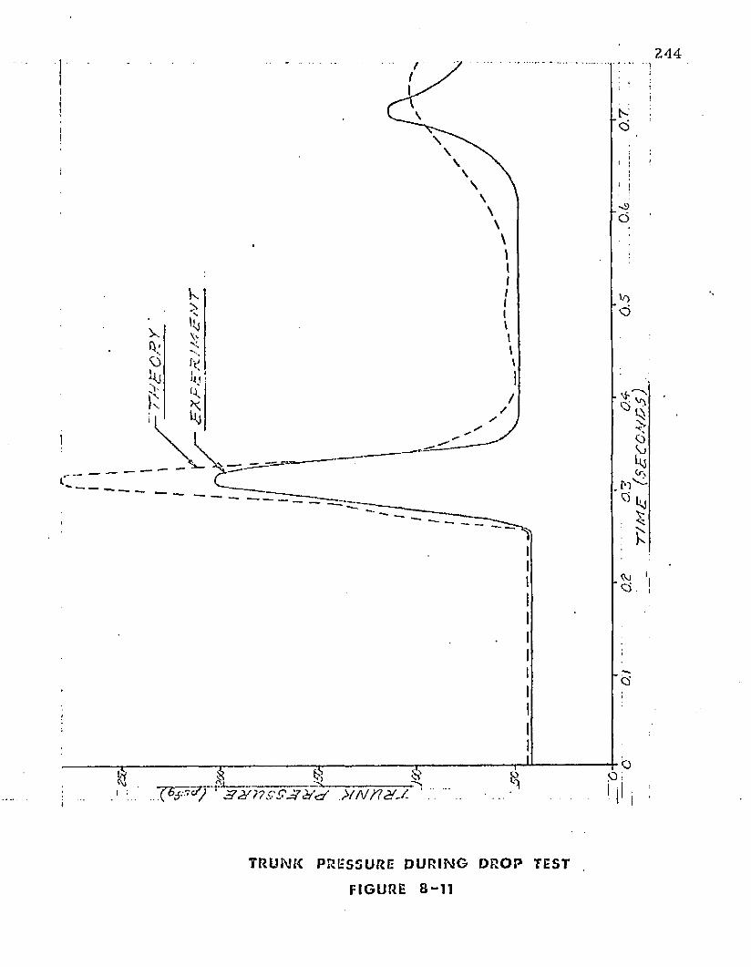
2 4 4
>fNKXJ-
T RUNK PRESSURE D U R I N G D R O P TEST
FIGURE 8 - 1 1
'T/M
E (S
EC
ON
DS
)
245
' o
’ f a & j / V 0 f j C t / ^ J : r f 3 2 0 V
a c c e l e r a t i o n d u r i n g d r o p t e s t
FIGURE 8 - 1 2 .
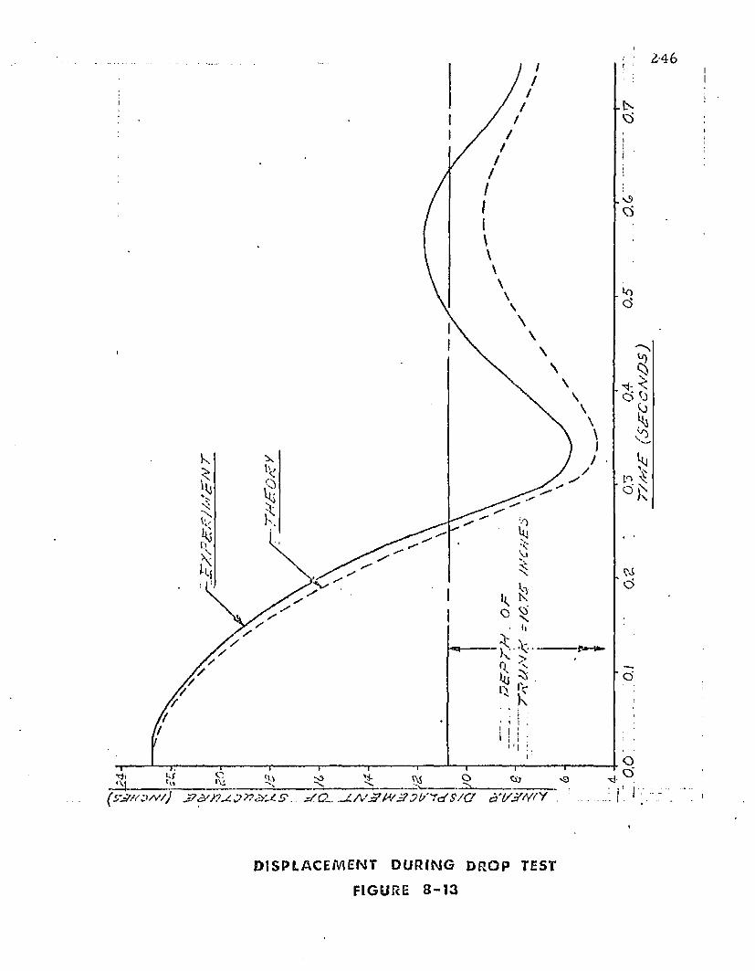
2 4 6
< C> K
x
“ Hi
■ o '
(y ^ /v ;w /y . ^ C - u L /V ^ rfV ^ y U 'y d '$ /a y
1
D I S P L A C E M E N T D U R I N G D R O P TEST
FIGURE 8 - 1 3
247
8 .8 Sum m ary of Dynam ic Tost Results
T he model d rop tes t was c o n d u c te d in o rder to com pare th e experim ental results
with the c o m p u te r pred ic tion of th e dynam ic response.
T he fan speed a t d rop was 8 ,0 0 0 rpm and the d rop height was one foo t. The
experim entally de te rm ined s ta t ic characteristics show n in Figures 8-7, 8-8, 8-9, and 8-10
were used as inpu ts to th e c o m p u te r program.
The variation of t ru n k pressure w ith t im e for the experim ental and the c o m p u te r
results are show n in Figure 8-11. The shapes of the tw o curves are qu i te similar. However,
the peak pressure pred icted by the c o m p u te r was higher th an th a t m easured.
Figure 8-12 com pares the p red ic ted and measured values o f th e vertical
acceleration. As in th e case of th e pressures, th e curves are similar in shape. However, th e
experim entally m easured acceleration was slightly higher th an th a t predicted .
Figure 8-13 com pares th e p red ic ted and m easured values o f displacem ent. The
curves are similar in shape, b u t the m axim um predic ted d isp lacem ent is slightly greater than
the m easured d isplacem ent.
Figures 8-11 th rough 8-13 show th a t it is possible to analytically p red ic t th e
general characteristics o f the dynam ic response on the model tes ted . T he analysis presented
in Section -7.3 represents a valuable design tool fo r evaluating th e effec t on dynam ic
response of changes in the various design variables.
9. SUMMARY OF RESULTS
9.1 Design Considerations
In th is report, th e static and dynam ic perform ance characteristics of the air
cushion landing system were considered. The perform ance characteristics which are
associated with static equilibrium include the following:
load capacity
stiffness
obstacle clearance
Additional perform ance characteristics associated with the dynam ic perform ance
.of the system include: vertical (landing) energy absorp tion characteristics, horizontal energy
absorption characteristics (braking and frictional drag), and system stability. The horizontal
energy absorp tion and system stability were n o t considered in this study.
The load capacity is generally a specified design requirem ent which is de term ined
by the aircraft design.
T he system stiffness is dependen t upon the t ru n k shape, t ru n k pressure, and the
configuration o f th e cushion. It is desired to design th e t runk so th a t pitch, roll, and heave
stiffness are adequate . However, it should be noted th a t t ru n k stiffness is also an im portan t
param eter in designing the air cushion system for landing energy absorption. This
consideration m ay becom e th e overriding fac to r in specifying the t ru n k stiffness.
T he obstacle clearance is related to the daylight clearance (d), the t runk height
(Y0 ), and th e design of the jets and the t runk . It is generally desired to have large values of d
for m axim um ground perform ance b u t small values of d for m inim um power. It is possible,
248
249
th ro u g h using a flexible t ru n k w ith d is tr ibu ted jets, t o provide a d e q u a te g round
pe rfo rm ance fo r low values of d. T h e value of d necessary fo r a d e q u a te g round pe rfo rm ance
fo r a given t ru n k and je t con figu ra t ion m ust, a t p resen t, be de te rm in e d experim en ta l ly . T h e
resulting value of d is an im p o r ta n t variable in de te rm in ing pow er req u irem e n ts fo r a d e q u a te
g ro u n d p e rfo rm ance .
T h e design Variables m ay be subd iv ided in to th e fo llow ing fo u r areas: aircraft, je t
sys tem , t ru n k , a n d pow er system .
T he a irc ra f t variables include th e w eight to be su p p o r te d (W ^), th e length (D 2 ),
w id th (D-j), a rea (A q), an d th e pe r im e te r (S) of th e air cush ion , and th e day ligh t c learance
(d) be tw een th e t ru n k an d th e g round . A ddit iona l variables w hich e n te r in to th e d y n am ic
pe rfo rm ance include tak e -o ff and landing speeds, loads and a tt i tu d e s , vertical velocity a t
to u c h d o w n , brak ing coeff ic ien t and braking d istance.
T he je t system variables include th e ty p e of jets (slots, holes, nozzles, e tc .) , th e jet
spacing, th e n u m b e r o f jot row s (M), t h e loca tion o f th e jet row s o n th e t r u n k ( X n ), th e
effective jet th ickness ( tn ), and th e effec tive jet angle ( 0 n ).
T h e t r u n k variables include th e location of a t ta c h m e n t poin ts , (o, o) and (a, b ) ,
t h e t ru n k length (2 ) and th e elastic charac te r is t ics o f th e t ru n k m aterial (E).
T he . p o w e r sys tem variables include th e h o rse p o w er inpu t (hp) an d the pressure
(Pj) versus f low (Qj) charac te r is t ics o f th e fan.
■ - I t is desired t o se lec t values fo r th e design variables in such a way th a t
p e rfo rm a n c e req u irem en ts a re m e t and th e pow er, w eight, and cos t o f th e system are
m inim ized . T h e design req u irem en ts m ay be specified in te rm s o f a irc ra f t w eight, jet height,
and t ru n k stiffness, and m ax im um a llow able dece le ra t ion du ring landing im pact.
T he re la tionsh ip be tw een groupings of th e design variables are expressed
th ro u g h o u t th is re p o r t in te rm s o f p c/p j. It shou ld be n o te d th a t w h e n th e a irc ra f t is to ta l ly
su p p o r te d by th e cush ion , p c is c o m p le te ly d e te rm in e d by th e su p p o r te d w eigh t and
cush ion area. T h e e ffec t of increasing pow er is to increase pj, w hich in tu rn increases je t
2 5 0
flow . T h e m ajo r e ffec t of increased f low is to increase th e je t height, d. It is ev iden t t h a t th e
ra t io o f Pc/Pj is an im p o r ta n t pa ram ete r w hich rela tes th e variables of w eigh t, po w er and jet
he ight. T h e t ru n k stiffness and t ru n k shape a re also fu n c t io n s of pc /p j . C o n seq u en tly , th e
ra t io pc /p j fo rm s an im p o r ta n t link be tw een th e d e p e n d e n t and in d ep e n d e n t variables.
In th e fo llow ing sections, th e re la tionsh ips be tw een th e various design variables
have been sum m arized.'
9 .2 A irc ra ft Variables
T h e principal a irc ra f t variables are as fo llows:
Ac-cush ion area
D-|-cushion w id th
D2 -cushion length
d-day liyh t c learance (jet height}
S-cushion perim eter
W ^ -a irc ra f t w eight
V ery little design flex ib ility is generally a llow ed in th e a ircraf t variables. T he
c ush ion area and shape are generally d e te rm in e d by th e a irc ra f t design. S im ilarly , th e w eight
o f th e a irc ra f t is specified . T he je t he igh t is specified b y th e obs tac le nego tia t ion and g round
p e rfo rm a n c e requ irem en ts .
A re la tionsh ip be tw een th e principal a irc ra f t variables and th e p o w e r requ irem en ts
m ay be deve loped by com bin ing E qua tions (2-9) and (3-7). T he result is
\ 1/2hp = 2 9Q
'h d (9-1)
This re la tionsh ip show s th a t am ong th e a irc ra f t variables it is desirable to
m ax im ize A c a n d m inim ize S and d fo r m in im um pow er. T h is re la tionsh ip is fu r th e r
251
i llustrated by Figure 3-5 which shows th a t the augm en ta t ion ratio is increased by increasing
cushion area for a f ixed value of d.
A fu r th e r consideration in designing th e air cushion system is th e p itch and roll
stiffness offered by th e t ru n k . It is desired to place the t ru n k as far from the c en te r of
gravity as possible to increase th e restoring m o m e n t developed by the t runk .
C onsequen tly , it is desired to m ake th e a ircraft fuselage as wide as is p e rm itted by
ae rodynam ic and structu ra l considerations. A n o p tim um cushion shape fo r an a ir cushion
landing system w ould p robab ly involve a fuselage with a higher w id th to length ratio than
exists in normal a ircraft designs.
9 .3 J e t System Variables
T he jet system variables include:
d - je t height
p c /p j - p re s s u re ratio
N — n u m b er o f jet rows
t — total je t th ickness
t n — je t th ickness fo r individual rows
X n — location of individual rows on the t ru n k
0 n — effective jet angle fo r individual rows
In add it ion , th e use of s lo ts versus holes fo r th e jet nozzle m ust be considered.
T h e d iam ete r and spacing betw een th e holes m ust be de te rm ined if holes are selected.
T he selection of pc /pj is de te rm ined largely by the cushion system stiffness and
vertical energy abso rp t ion desired. Low values o f p c/pj give a s tiff cushion while high values
o f pc /p j give a so f t cushion. T he influence of Pc/Pj on pow er is show n in Figure 3-4(a). The
power-height pa ram ete r is d irectly p roportiona l to pow er fo r c o n s ta n t vehicle weight,
252
area, perim eter, and je t height. T he curves sh o w th a t pow er requ irem en ts are relatively
insensitive to pc/p j fo r th e range o f 0 .5 to 0 .9 . Figures 3 -4 (b) and 3-4(c) also sh o w th e e ffec t
o f je t angle on pow er requ irem en ts . A n increase in je t angle f rom 0 ° to 3 0 ° results in a
considerab le decrease in pow er. F u r th e r increases have m in o r influence on pow er. Negative
je t angles and je t orifices to th e ou ts ide o f th e t ru n k low po in t (XQ, Y Q) were show n in
C hap ters 5 and 6 t o c o n tr ib u te practically no th in g to je t height.
T h e je t th ickness t is se lec ted to p rovide th e desired level o f p c /p j fo r th e design
weight, je t height, and pow er setting.
F ro n t and rear t ru n k sec tions generally requ ire m ore jets th an side t ru n k sections.
T he reason fo r th is m ay be seen by com paring Figure 4-21 and Figure 4-22. These figures
sh o w t h a t fo r a given de flec t ion , th e end t ru n k has a longer length f la t ten ed against th e
g round ( £ 3 ) th an th e side t ru n k . In a d d it ion , th e rear t ru n k undergoes extensive f la t ten ing
du ring take-off ro ta t io n and landing to u ch -d o w n . Inadequa te air lubrication w ould
c o n tr ib u te to plow-in of th e f ro n t t ru n k and excessive w ear of th e a f t t ru n k .
Because of th e co m p lex ity of th e f low benea th th e t ru n k , an o p t im u m spacing
and nozzle design c a n n o t a t p resen t be p red ic ted analy tica lly . However, the analysis
p resen ted in th is re p o r t is useful in de te rm in ing t re n d s and ex trapo la t ing experim enta l
results. In particu lar, t h e pow er-je t-height p a ram ete r (C|lcj) is a valuable p a ram ete r fo r th is
purpose.
T he Cjlcj p a ram ete r was defined by E qua tion (3-7) in Sec tion 3.6.
c hd " — d
Pj 3 /2
\ p c /
CQ cx (3-7)
T he values o f t / d and C q as a fu n c t io n o f p c /p j m ay be de te rm in e d b y th e sim ple
te s t described in C hap te r 6 on a m odel section o f t ru n k . T h e te s t rig fo r c o n duc ting such a
te s t was show n in Figure 6-1. T he te s t fo r de te rm in ing C ^ was described in A ppend ix VI. As
253
a resu lt o f th e s e sim ple tes ts , it is possib le t o p lo t versus p c/p j fo r a p a r t icu la r je t
c o n f ig u ra t io n . A co m p ar iso n of th ese p lo ts fo r various je t c o n f ig u ra t io n s a llow s th e
eva lua tion o f th e designs in e ff ic iency o f m ax im iz ing je t h e igh t a n d m in im iz ing ho rsepow er .
A s a c o n seq u e n c e it is desirab le to se lec t th e design w hich m in im izes C ^ ,
p rov ided w e igh t, cost, o r o th e r f ac to rs d o n o t d ic ta te th e se lec tion . O th e r f a c to rs include
th e necess i ty to p rov ide " a i r lu b r ic a t io n " b e n e a th th e t r u n k during landing im pac t, an d to
s tab ilize d y n a m ic osc illa tions of t h e t r u n k u n d e r all o pera t ing co n d it io n s .
A c o m p a r iso n o f C f ^ fo r t w o t ru n k designs is sh o w n in Figure 0-1. In th e figure,
e ight ro w s o f orifices, t h e design descr ibed in A p p e n d ix IV, is c o m p a re d w ith a design w hich
has f o u r tran sve rse slots. B o th designs had th e sam e to ta l nozz le area . T h e curve show s th a t
th e s lo t des ign is b e t t e r fo r high p c/p j while t h e orif ice design is b e t t e r fo r low Pc/ Pj - It is
ev iden t f ro m F igure 9-1 t h a t th e C|lcj gives a s im ple vehicle fo r c o m p a r in g c o m p e t in g designs
w i th o u t t h e n e e d fo r a c o m p lic a ted analysis.
9 .4 T r u n k Variables
T h e t r u n k variables inc lude :
(o ,o) a n d (a, b) — th e t r u n k a t t a c h m e n t p o in ts
£ — th e t r u n k length
E — th e t r u n k m ateria l e la s t ic i ty
Pj — t h e t r u n k p ressure
T h e t r u n k s tiffness m ay be in f luenced c ons ide rab ly by choos ing a p p ro p r ia te t r u n k
lengths a n d a t t a c h m e n t po in ts . T h e load s u p p o r te d b y th e t r u n k is p ro p o r t io n a l to Pj (the
It was s h o w n in E q u a t io n (^-1) t h a t h o rse p o w er is d irec tly p ro p o r t io n a l to C|icj.
(9-1)
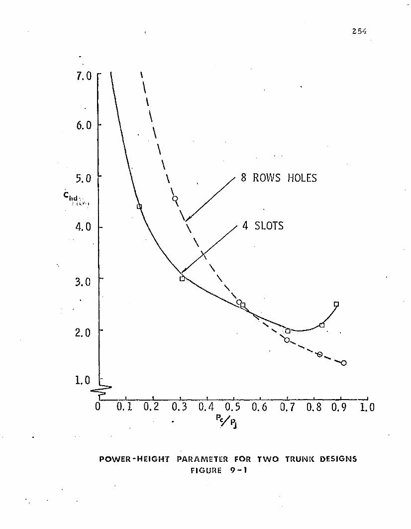
2 5 4
7.0
6.0
8 ROWS HOLES5.0
hd
4 SLOTS4 .0
2.0
1.0
0 0 .1 0 .2 0 .3 0 .4 0.5 0 .6 0.7 0 .8 0 .9 1.0
V P j
P O W E R - H E I G H T P A R A M E T E R FOR T W O T R U N K D E S I G N S
FI GURE 9 - 1
255
t ru n k pressure) and to £ 3 ( the length f la t tened against th e ground). The relationships
be tw een £ 3 a n d t ru n k deflection are show n in Figures 4-21 and 4-22; th e tw o t ru n k s having
d iffe ren t a t t a c h m e n t points. The stiffness variation, scaled up to a C-119 aircraft size t ru n k ,
is show n in Figure 9-2. T he curves show n in Figure 4-21 and Figure 4-22 are scaled up to
p roduce curves " A " and " B " respectively in Figure 9-2. T he following assum ptions were
m ade:
All d im ensions are scaled up by a fac to r o f 3 .00 .
T h e design pc /pj is 0.5.
T h e t ru n k is inelastic.
T h e design t ru n k pressure is 333 lb /f t^ .
T h e t ru n k section is 5 0 0 ” in length.
T h e stiffness o f th e tw o t ru n k sections was fo u n d to be 2 0 0 0 lb/in. fo r t ru n k " A "
and 6 0 0 0 lb /in . fo r t ru n k " B " . The stiffness of th e air spring on th e conventional C-119
shock s tru t is a round 4 5 0 0 lb/in. It is evident from th is simple illustration th a t considerable
flexibility ex ists in designing t ru n k stiffness by appropria te selection of the t ru n k variables.
In a m an n e r similar to th e illustration above, the stiffness fo r any t ru n k design may be
calcu la ted f ro m th e c o m p u te r program results.
T h e selection o f th e t ru n k material elasticity is based on the d ifference betw een
th e re t rac ted length and th e desired infla ted length. It is desirable to have a c o m p o u n d
elastic curve w ith tw o d iffe ren t slopes. A typical curve is show n in Figure 4-14. T he material
show n has t h e slope characteris tic o f th e rubber up to th e inflated design p o in t and th e
slope of t h e fabric reinforcing material above the design poin t. Such an elastic characteris tic
allows th e material to s tre tch easily up to th e design po in t b u t resists fu r th e r e longation
above the design point.
T h e analysis of th e air cushion t ru n k shape developed in C hap ter 4 and the
c o m p u te r program s developed in A ppendices I, II, and III provide the capability of
pred ic ting t h e influence o f all th e t ru n k variables on th e t ru n k and cushion stiffness. In
256
a d d i t io n , th e d y n a m ic analysis dev e lo p ed in C h ap te rs 7 a n d 3 p rov ides t h e cap ab i l i ty of
evalua ting th e in f luence of all t r u n k design variables e x c e p t t r u n k e las t ic ity , o n th e d y n a m ic
response o f t h e vehicle.
T h e p o w e r sy s tem variables inc lude :
h p — p o w e r in p u t
Qj — air f lo w ra te
Pj — t r u n k pressure
T h e f lo w ra te is d e te rm in e d f ro m E q u a t io n (3-3), w h ich m ay be w r i t te n :
T he coeff ic ien t Cq is a function o f Pc /Pj and is show n in Figure 3-2.
T he power system must be designed so that the desired f low rate is produced at
t h e design pj. F u r th e r , th e fan ch a rac te r is t ic s s h o u ld be c h o sen such t h a t th e necessary f low
will be p r o d u c e d t o m a in ta in p c/p j in an a c c e p ta b le range over t h e e x p e c te d v a r ia t ions o f p c
caused b y changes in t h e a irc ra f t o p e ra t in g w e igh t. U n d e r land ing im p a c t , it is possible f o r pj
t o increase t o th e p o in t w h e re th e fan s ta lls a n d reverse f lo w occurs . T h e fan sh o u ld be
designed to p e rm i t a n d w i th s ta n d th is c o n d i t io n .
C onsidering o n ly s ta t ic c o n d i t io n s , t h e desired Pj versus Qj fan ch arac te r is t ic s m ay
be o b ta in e d f ro m E q u a t io n (3-3). This e q u a t io n gives th e req u ired f lo w fo r va rious levels of
Pj a n d p c/p j . T h e value o f C Q a s a fu n c t io n o f pc /p j is given in F igures 3-2, 5-7, a n d 6 -12 fo r
va rious cu sh io n designs.
In a d d i t io n , th e fan c h a rac te r is t ic s p lay an im p o r ta n t ro te in t h e d y n a m ic response
o f th e sy s tem . T h e fan f lo w ch a rac te r is t ic s n ea r an d above stall p ressure have a p ro fo u n d
9 .5 P o w er S y s tem V ariables
(3-3)
in fluence on th e m ax im u m t ru n k pressure and m ax im u m decele ra tion during im pact. T he
e ffec t o f fan charac te r is t ics on d y n a m ic response m ay be evaluated using th e d y n am ic
analysis d eve loped in C h a p te r 7.
9 .6 Pow er R equ irem en ts fo r th e ACLS
T h e p o w e r req u irem e n ts fo r th e ACLS m ay be scaled up using E qua tions (9-1)
and (3-7).
hp =f WA \ 3 /2 S d 2 g 0 ' 1 /2
550'h d (9-1)
c - | Pi c h d I —
3 /2
C Q c x (3-7)
T h e C|icj p a ra m e te r is d im ension less a n d in d ep e n d e n t of scale. Th is p a ra m e te r
m ay be easily m easu red fo r a given t ru n k design b y m odel tes t ing . T h e values of p an d gQ
are also in d e p e n d e n t o f vehicle size. T he rem ain ing variables are d e p e n d e n t on a irc ra f t size
an d p e rfo rm a n c e requ irem en ts . In pa rt icu la r, th e value of d is rela ted t o th e g round
p e rfo rm a n c e requ irem en ts , and A c and S are re la ted to a irc ra f t w eight. A 2 5 0 0 p o u n d
a irc ra f t eq u ip p e d w ith an air cush ion landing sys tem has been tes ted and its take-o ff , landing
an d obs tac le nego tia t ion p e rfo rm a n c e was ex c e l le n t as rep o r ted in R eferences (3) and (50).
If it is assum ed t h a t t h e jet he igh t a n d C j ^ of th e te s t a irc ra f t design are sa tis fac to ry fo r
larger a irc ra f t , th e p o w er req u irem e n ts fo r larger a irc ra f t m ay be es t im a ted f ro m E qua tion
(9-1).
T o d e te rm in e th e re la tionsh ip be tw een th e pow er and a ircraf t w eigh t, som e
d e p e n d e n c e be tw e en w eigh t an d fuselage area, an d w eigh t an d fuselage pe rim ete r , is
necessary.
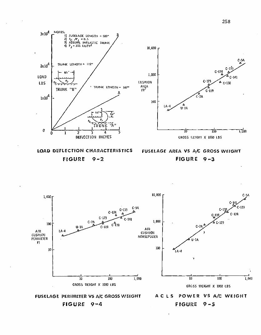
258
3xl04 NOTES‘I) rU SELAGC LEN G TH " KXT J ) PC / P , “ O . i3) A S S U M E IN E L A S T IC4) P j = 3 33 LB/FT2
IK UN K
A TRUNK L E N G T H » 1122 x 1 0
L OA DL B S
* TRUNK LEN G TH = 1 67 'T R U N K " B
A1x10
0D E F L E C T I O N I N C H E S
10,000
C - 5 A
C - 133C - 124
1.000C - 123C U S H I O N C- 130
C - 1 1 9
C 7A
100L A -4 U 1 A
1,000ID 100C R O S S W E IG HT X 1000 LBS
LOAD D E F L E C T I O N C H A R A C T E R I S T I C S FUSELAGE AREA VS A/C G R O S S W E I G H T
F I G U R E 9 - 2 F I G U R E 9 - 3
10,000 C - 5 A1,000
C - 5 A C-13JC - 133C - 1 2 4
C - 1731,000C - 7 A n C - 1 2 3100
C - 7 AC - 1 1 9U - 1 AA I R
C U S H I O NP ER IM E TE R LI- 1A
100L A -4
1001,000 1,00010 100
C R O S S W E IG H T X 1000 L BS G R O S S W E I G H T X 1 0 00 L B S
FUSELAGE PERIMETER VS A/C GR O SS W E I G H T A C L S P O W E R V S A/ C W E I G H T
F I G U R E 9 - 4 F I G U R E 9 - 5
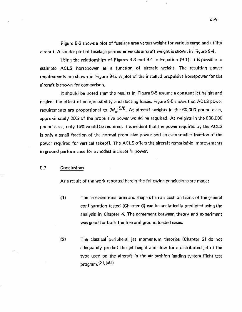
259
Figure 9-3 shows a p lo t o f fuselage area versus w eight fo r various cargo and utility
aircraft. A similar p lo t o f fuselage perim eter versus a ircraft w eight is show n in Figure 9-4.
Using th e relationships of Figures 9-3 and 9-4 in Equation (9-1), it is possible to
es tim ate ACLS horsepow er as a func t ion o f a ircraft weight. T he resulting power
requ irem en ts are show n in Figure 9-5. A p lo t o f the installed propulsive horsepow er for the
a ircraft is show n fo r com parison .
It shou ld be noted th a t th e results in Figure 9-5 assume a cons tan t je t height and
neglect th e effec t of com pressib ility and ducting losses. Figure 9-5 shows th a t ACLS power
requ irem en ts are p roportiona l to (Wc )^ ® . A t a ircraft weights in the 6 0 ,0 0 0 po u n d class,
ap p ro x im ate ly 20% of the propulsive pow er w ould be required . A t weights in th e 600 ,000
p o u n d class, on ly 15% w ould be required . It is evident th a t th e power required by th e ACLS
is on ly a small f rac tion of th e normal propulsive pow er and an even smaller f rac tion o f th e
pow er required fo r vertical takeoff. The ACLS offers th e a ircraft rem arkable im provem ents
in g round pe rfo rm ance for a m odest increase in power.
9.7 Conclusions
As a result o f the w ork repo r ted herein th e following conclusions are m ade:
(1) T he cross-sectional area and shape o f an air cushion t ru n k o f th e general
configuration tes ted (Chapter 6) can be analytically p red ic ted using th e
analysis in C hap ter 4. The agreem ent be tw een th eo ry and experim en t
was good for b o th th e free and g round loaded cases.
(2) T he classical peripheral je t m o m e n tu m theories (Chapter 2) do n o t
adequate ly p red ic t th e jet height and flow for a d is tr ibu ted jet o f th e
t y p e used on th e aircraft in th e air cushion landing system flight tes t
p r o g r a m . ^ ' ^ ®
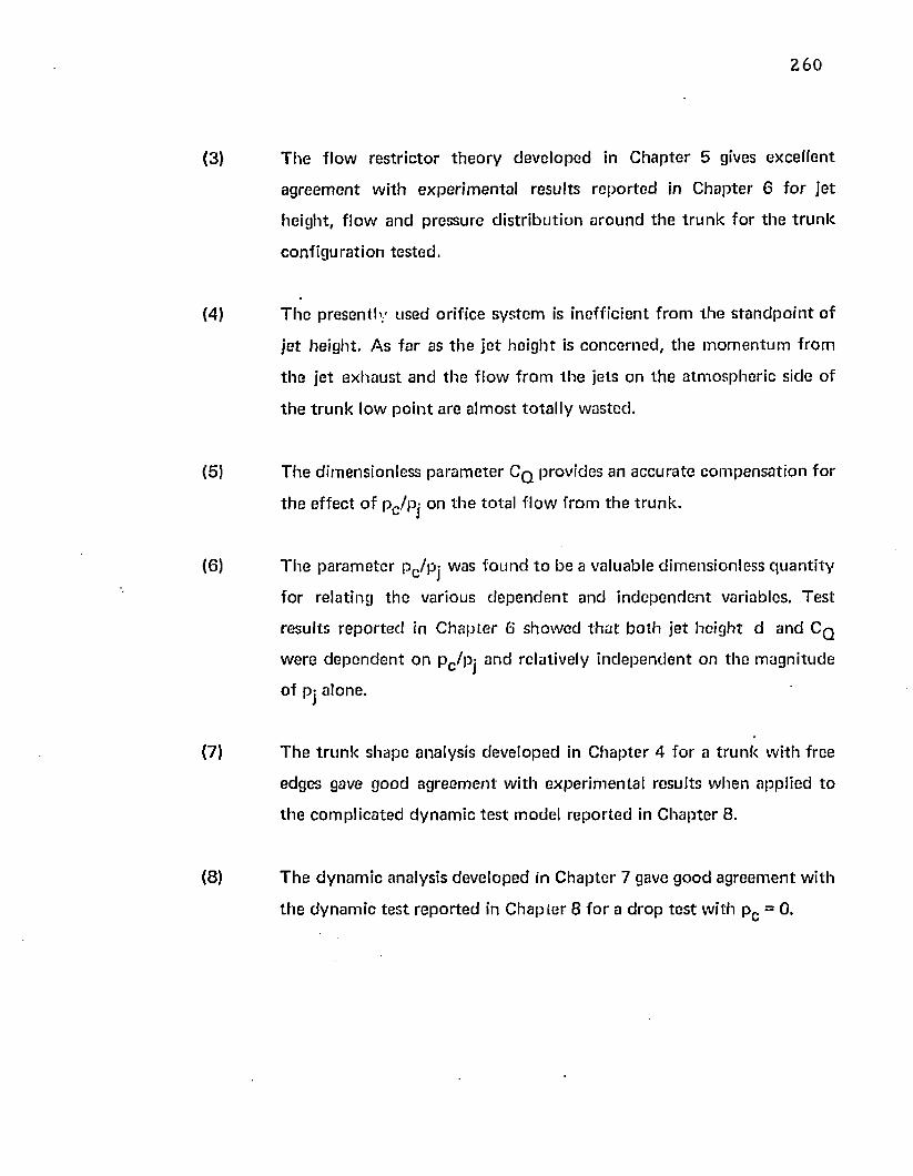
2 6 0
(3) T h e f lo w re s t r ic to r th e o r y dev e lo p ed in C h a p te r 5 gives exc e l le n t
a g re e m e n t w ith e x p e r im e n ta l resu lts r e p o r te d in C h a p te r 6 fo r je t
h e igh t , f lo w an d p ressure d is t r ib u t io n a ro u n d th e t r u n k fo r t h e t r u n k
c o n f ig u ra t io n tes ted .
(4) T h e p re se n t ly used orif ice sy s tem is ineff ic ien t f ro m th e s t a n d p o in t o f
je t he igh t. A s f a r as t h e j e t h e igh t is c o n c e rn e d , t h e m o m e n tu m f ro m
t h e j e t e x h a u s t an d th e f lo w f ro m th e jets on th e a tm o sp h e r ic side of
t h e t r u n k low p o in t a re a lm os t to ta l ly w asted .
(5) T h e d im ension less p a ra m e te r C q provides an a c c u ra te c o m p e n s a t io n fo r
t h e e f fe c t o f Pc /Pj on th e to ta l f lo w f ro m th e t ru n k .
(6) T h e p a ra m e te r p c /p j was fo u n d t o b e a va luab le d im ension less q u a n t i ty
fo r re la ting th e various d e p e n d e n t a n d in d e p e n d e n t variables. T es t
resu lts r e p o r te d in C h a p te r 6 sh o w e d t h a t b o th je t h e ig h t d a n d C q
w ere d e p e n d e n t o n p c /p j an d rela tively in d e p e n d e n t on th e m ag n i tu d e
o f pj a lone.
(7) T h e t r u n k shape analysis de v e lo p e d in C h a p te r 4 fo r a t r u n k w ith free
edges gave good a g re e m e n t w ith e x p e r im e n ta l resu lts w h e n app lied to
th e c o m p lic a ted d y n a m ic te s t m odel r e p o r te d in C h a p te r 8.
(8) T h e d y n a m ic analysis dev e lo p ed in C h a p te r 7 gave g o o d a g re e m e n t w ith
t h e d y n a m ic te s t r e p o r te d in C h a p te r 8 f o r a d ro p t e s t w ith p c = 0.
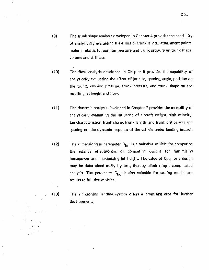
*
261
(9) T he t ru n k shape analysis developed in C hap ter 4 provides th e capability
of analytically evaluating th e effec t of t ru n k length, a t ta ch m e n t points,
material elasticity , cushion pressure and t ru n k pressure on tru n k shape,
vo lum e and stiffness.
(10) T he f low analysis developed in C hapter 5 provides th e capability of
analytically evaluating the effec t o f je t size, spacing, angle, position on
th e t ru n k , cush ion pressure, t r u n k pressure, and t ru n k shape on th e
resulting je t height and flow.
(11) T he dynam ic analysis developed in Chapter 7 provides th e capability of
analy tica lly evaluating th e influence o f a ircraft weight, sink velocity,
fan characteristics, t ru n k shape, t ru n k length, and t ru n k orifice area and
spacing on th e dynam ic response o f th e vehicle u n d e r landing impact.
(12) T he dim ensionless param eter C ^ is a valuable vehicle fo r com paring
th e relative effectiveness of com peting designs fo r minimizing
horsepow er and m aximizing je t height. T h e value of C|1cj fo r a design
m ay be de te rm ined easily by tes t , th e reby eliminating a com plicated
analysis. T he pa ram ete r C j^ is also valuable fo r scaling m odel tes t
results t o full size vehicles.
(13) T h e air cushion landing system offers a promising area fo r fu r the r
deve lopm en t. .
A ppendix I
FR EE T R U N K SHAPE (INELASTIC)
T he c o m p u te r program described in th is a p pend ix c om pu tes th e cross-sectional
shape for a free inelastic t ru n k . The logic is similar to th a t p resen ted in Section 4 .4 , b u t with
th e restric tion th a t the t ru n k is inelastic.
T he inpu t variables are
a = x co o rd in a te of upper t ru n k a t ta c h m e n t po in t
b = y co o rd in a te of upper t ru n k a t ta c h m e n t po in t
pc/pj = ra t io of cushion pressure to t ru n k pressure
C = t ru n k length
T he program uses a and b to m ake an initial es tim ate R-j and c om pu tes 2 =
J2 (R-j). Improved estim ates on R^ are m ade until | £ — fi| > (T O L )(C ) . T O L is th e
relative to le rance on 2 . This to le rance is se t a t 3 x 10 '^ . This can be changed b y inserting a
new card.
T he m ain program m ay call th re e subrou tines: fu n c t io n F(R-|) evaluates £(R-|) —
£ = F{R-j); func t ion DF(R-j ) evaluates th e derivative of F(R^) ; sub rou tine RTMI uses
Mueller's Iteration M ethod t o converge on th e so lu t ion of FfR-j) = 0, once th e so lu tion is
bounded .
Initially, th e program converges on th e so lu tion of F (R -j) = 0 from th e right side
using N ew ton 's i te ration m ethod .
If th e so lu tion is b o u n d e d during th e N ew ton i te ration process, th e Mueller
su b ro u tin e is called to speed convergence, and a n o ta t io n is m ade in th e da ta o u tp u t to
indicate th a t th is su b ro u tin e was used.
262
2 6 3
T h e p ro g ram has been fo u n d t o converge fo r t h e range o f variab les w hich a re o f
p rac tica l in te res t . F o r e x tre m e ly small values o f 2 (say « V a 2 + b 2 ), an im p ro v ed initial
guess o n R-j is necessary . Th is m ay be d o n e b y inserting a card in th e lo ca t ion n o te d in th e
p rog ram . T h e variable p c /p j is re s tr ic ted t o values less t h a n 1.0.
T h e o u t p u t gives t h e values o f all in p u t variables, t h e n o ta t io n M ueller if th e
RTMI s u b ro u t in e was ca lled , a n d th e final va lues o f th e fo llow ing variab les: Aj , R-j, R 2 , X Q,
Vo' V i ' V2' ° V a n d °2■
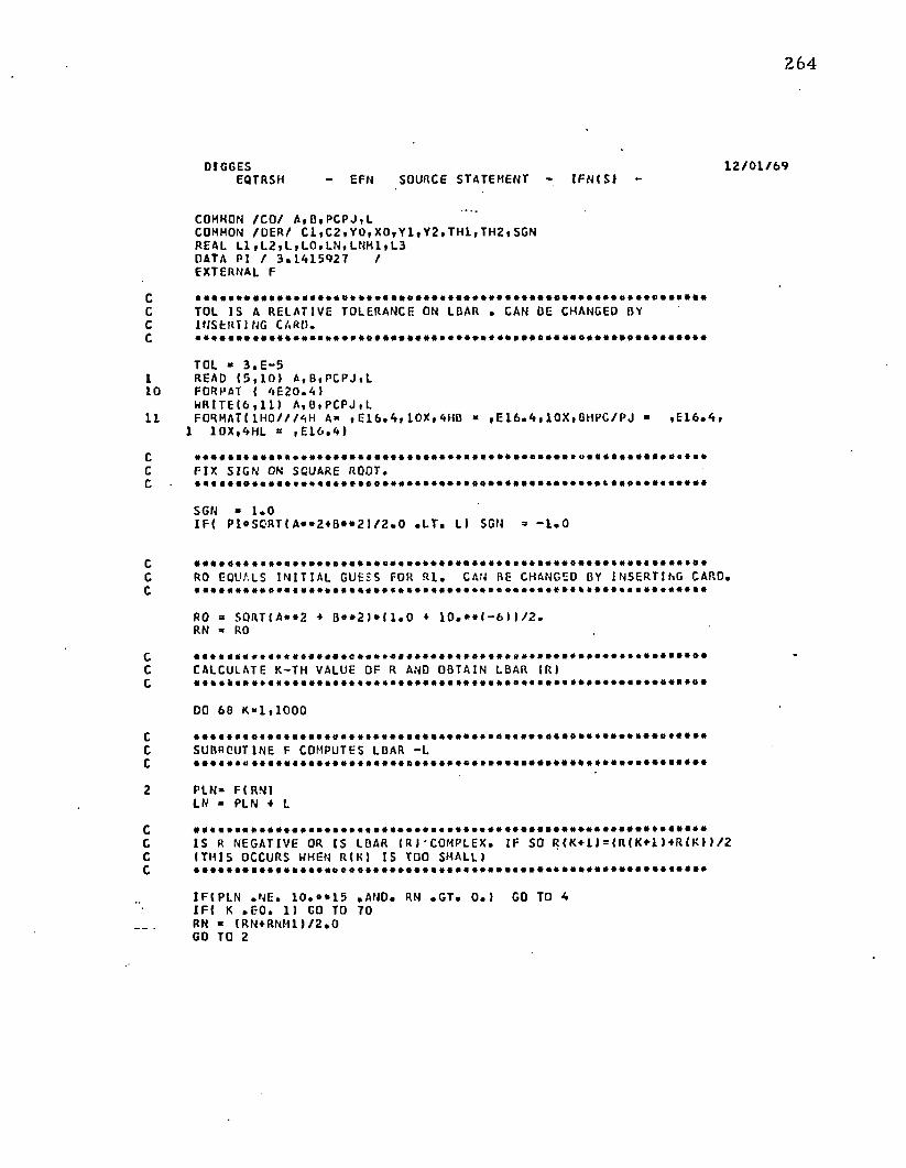
onoo
ro
o o
r> no
o o
o o
non
►*-*
**•
o n
o o
2 6 4
D I G G E S 1 2 / 0 1 / 6 9E Q T R S H - E F N S OU R C E S T A T E M E N T - I F N ( S ) -
COMMON / C O / A , B , P C P J , LCOMMON / O E R / C 1 , C 2 , Y 0 , X 0 , Y 1 , Y 2 , T H 1 , T H 2 , S G N REAL L 1 , L 2 , L , L 0 , L N , L N M 1 , L 3 DATA PI / 3 . 1 A 1 5 9 2 7 /EXTERNAL F
TOL I S A RELATIVE TOLERANCE ON LBAR . CAN BE CHANGED BY INSERTING CARO.
TOL - 3 . E - 5READ ( 5 , 1 0 ) A , B , P C P J , L
0 FORMAT ( A E 2 0 . A )MR 1T E ( 6 , 1 1 ) A , 0 , P C P J , L
1 F O R MA T ! 1 H 0 / / / 4 H A” , E 1 6 . A , 1 0 X , A H B ■ , E 1 6 . A , 1 0 X , BHPC/ PJ - , E 1 6 . 4 , 1 10X, AHL * , E 1 6 . A )
FI X SIGN ON SQUARE ROOT.
SGN - 1 . 0I F ( P I ® S O R T ( A ® * 2 * B * * 2 ) / 2 . 0 . L T . L) SGN = - 1 . 0
•a*®®®®.®®..**.*...*®.®®®.*.®®....*.*.®..*.®®*®®.®®*..®®®®®*®®®RO EQUALS I NI TI AL GUESS FOR R l . CAN BE CHANGED BY INSERTING CARD.
RO = SORT( A**2 + B ® * 2 ) * ( 1 . 0 + 1 0 . * * ( - 6 ) ) / 2 . RN ® RO
•■•••••«®<««®®®®«®®®®®®.«®®®®®®®®»B®®»*«»»®®®®®»®®«®®®*®®®®®®®®CALCULATE K-TH VALUE OF R AND OBTAIN LBAR (RI
DO 66 K* 1 , 1 0 0 0
SUBROUTINE F COMPUTES LBAR - L••••*®u*®®®*®®®**®**®®«®*®0®®*®***®»***®®«***®*****®**®®*®®*®**
PLN» F ( RNI LN « PLN + L
I S R NEGATIVE OR IS LBAR ( R I C O M P L E X . IF SO R ( K + l ) = ( R ( K + l ) +R! K) ) / 2 ( THI S OCCURS WHEN RI KI I S TOO SMALL)
I F ( PLN . N E . 1 0 . » ® 1 5 . AND. RN . GT. 0 . ) GO TO A I F t K . t - 0 . 1) GO TO 70 RN a ( RN+RNH1) / 2 . 0 GO TO 2
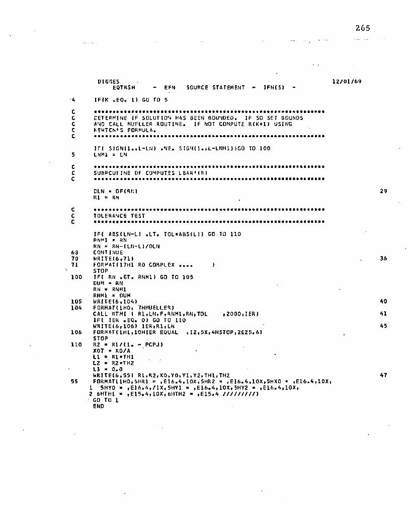
265
D I G G E S 1 2 / 0 1 / 6 9E Q T RS H - E F N S OURCE S T ATEME NT - I F N ( S 1 -
4 I F I K . E C . 1) GO TO 5
C ............................................................................................................... .. ................................ ..C DETERMINE IF SOLUTION HAS BEEN BOUNDED. IF SO SET BOUNDSC AND CAUL MUFLLER ROUTINE. IF NOT COMPUTE R I K + l ) USINGC NEWTON' S FORMULA.C ................................................................................................................................................................ ..
i n S 1 G N ( 1 . , 1 - L N ) . N F . S I GN! 1 • , L - L NH 1 ) I GO TO 1005 LNM1 = LN
C ...........................................................................................................................................................................C SUBROUTINE DF COMPUTES LBAR 1 ( R )C ..................................................................................................................................... ..........................
CUN * DF( RN) 2 9R1 ** RN
C .............* ..................C TOLERANCE TEST C .......................................
IF-C ABS( LN- L) . L T . TOL*ABStL I » GO TO 110 RNMl t RN RN * RN“ ! L N- L l / DL N
6 3 CONTINUE7 0 WR I T E < 6 , 7 1 ) 3 671 FORMAT!17H1 RO COMPLEX . . . . )
STOP1 0 0 I F ! RN . GT• RNMl) GO TO 1 0 5
DUM - RN RN - RNMl RNMl « OUM
105 W R I T E ( 6 , 1 0 4 ) 401 0 4 FORMAT! IHO, 7HMUELLER)
CALL RTMI ( R 1 , L N , F , R N M 1 ( RN, T0L , 2 0 0 0 , IERI 41I F ! 1EK . EQ. 01 GO TO 110W R I T E I 6 , 1 0 6 ) I E R , R 1 , L N 4 5
106 FORMAT! 1 H W1 0 HI E R EQUAL , 1 2 , 5 X . 4 HS T 0 P , 2 E 2 5 . 6)STOP
1 1 0 R2 « R1 / ( 1 . - P CPJ )X07 - XO/A LI « R l ' T H l L2 * R2*TH2 L3 - 0 . 0h R I T E I 6 , 5 5 ) R 1 » R 2 » X 0 , Y 0 » Y 1 , Y 2 , T H I , T H 2 4 7
55 FORMAT! 1H0, 5HR1 = , E 1 6 . 4 , 1 0 X , 5HR2 =■ , E 1 6 , 4 , 1 0 X , 5HX0 ■= , E 1 6 . 4 , 1 0 X ,1 5HY0 * , E 1 6 . 4 , / I X , 5 H Y 1 » , E 1 6 . 4 , 1 0 X , 5 H Y 2 - , E 1 6 . 4 , 1 0 X ,2 6HTHI * , E 1 5 . 4 , 1 0 X , 6 H T H 2 =* , E 1 5 . 4 / / / / / / / / / »
GO TO 1END
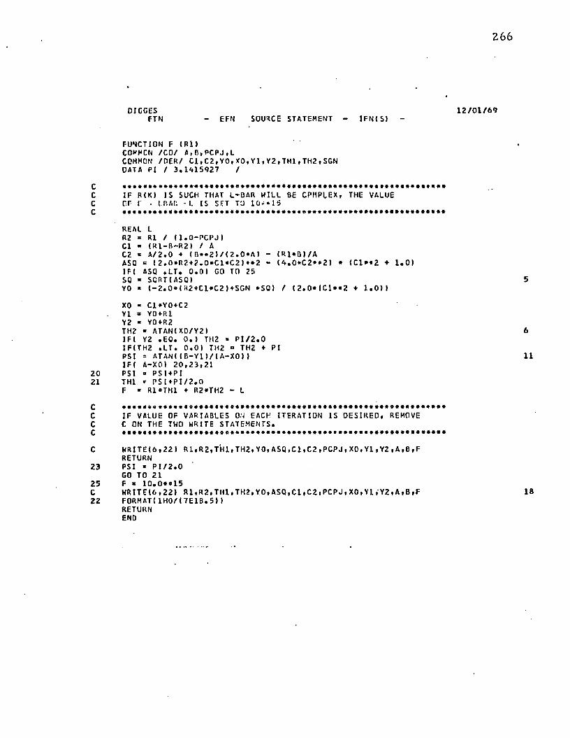
2 6 6
D I G G E S 1 2 / 0 1 / 6 9F T N - E F N S OURCE S T AT EME NT - I F N I S ) -
FUNCTION F ( R I )COMMON / C O / A , B , P C P J , LCOMMON / D E R/ C 1 , C 2 , Y 0 , X 0 , Y 1 , Y 2 , T H 1 , T H 2 , S G N OATA PI / 3 . 1 * 1 5 9 2 7 /
C ..................................... .. ................................................................................................ ....................................C I F R ( K ) I S SUCH THAT L-BAR HILL BE CPMPIEX, THE VALUEC CF «■ -1 LB A I'. - L IS SET TO 1 0 - * 15C .....................................................................................................................................................................
REAL LR2 « Rl / t l . O - P C P J I Cl ■ ( R 1 - B - R 2 ) / AC2 * A / 2 . 0 ♦ ! B * * 2 ) / ( Z . 0 » A I - ( R 1 » B 1/ AASQ = ( 2 . 0 * R 2 + 2 . 0 * C 1 « C 2 ) * *2 - ( A . 0 * C 2 * « 2 ) * <C1*«2 ♦ 1 . 0 )I F ( ASQ . L T . 0 . 0 ) GO TO 25SQ « SQRT(ASQ) 5YO - ! - 2 . 0 * ( R 2 + C l * C 2 ) + S G N *SQ) / ! 2 . 0 * < C l * * 2 + 1 . 0 ) )
XO - Cl * Y0+C2 Y1 * Y0 + R1 Y2 « Y0+R2 TH2 - AT A N ! X 0 / Y 2 )I F ! Y2 . E Q . 0 . ) TH2 >■ P I / 2 . 0 I F I T H 2 . L T . 0 . 0 1 TH2 « TH2 + P I PSI = A T A N I I B - Y l ) / ( A-XO t )IFF A-XO) 2 0 , 2 3 , 2 1
2 0 PSI » P S I + P I21 TH1 «• P S I + P I / 2 . 0
F » R1»TH1 + R2*TH2 - L
6
11
C ..............................................................................C IF VALUE OF VARIABLES ON EACH ITERATION IS DESI RED, REMOVEC C ON THE TWO WRITE STATEMENTS.C ..............................................* ..................................................................................................................
C WR I T E < 6 , 2 2 ) R l , R 2 , T H 1 , T H 2 , Y O , A S Q , C 1 , C 2 , P C P J , XO, Y1 , Y 2 , A , B , FRETURN
23 PSI * P I / 2 . 0GO TO 21
25 F ■ 1 0 . O o l 5C H R I T E I 6 , 2 2 ) R l , R 2 , T H 1 , T H 2 , Y O , A S Q , C l » C 2 , P C P J , X O , Y l , Y 2 , A , B , F 182 2 F O R M A T ! 1 H 0 / I 7 E 1 B . 5 ) )
RETURNEND
D I G G E SOE RF - E F N S OURCE S TATEME NT - I F N ( S ) -
FUNCTION D F ( R l )COMPCN / O E R / C l , C 2 , Y O t X O , V 1 , Y 2 , T H 1 , T H 2 , SGN COMMON / C O / A t t i t P C P J i L R E A L KK ■ 1 . 0 - PCPJCC1 " ( K - 1 . 0 ) / ( K• AI0C2 >= - S / AX * Rl / K 4 C1»C2V * C1 * • 2 4 J . OOX “ 1 . 0 / K 4 C1*0C2 ♦ C2»DC1CY « 2 , 0 * C 1 • CC12 « -SGN XSQRTI X * « 2 - Y» C2 »* 2)02 x U . o / ( 2 . 0 * 2 ) ) * ( 2 . 0 " X* DX - 12.0»Y»C2*>DC2 + C2«»2 • DY)) OYO - ( 1 . 0 / Y * * 2 J * I -Y ‘ ( 0 X 4 0 2 ) 4 (X + 2 ) * 0 Y )DXO x C1»DY0 + YO»OC1 ♦ 0C2 DY1 » OYO + 1 . 0 0Y2 * DYO ♦ 1 . 0 / K S - f l -Yl T x a-XOOST x ( 1 . 0 / T » « 2 ) * l - T « D Y l 4 S-DXOI 0K0Y2 « ( 1 . 0 / Y 2 * * 2 ) * (Y2»DX0 - X0*DY2)CPSI » DST/ ( 1 . 0 ♦ ( S / T ) * • 2 )0TH2 x DX0Y2 / ( 1 . 0 + ( X 0 / Y 2 ) « * 2 )DTH1 - DPSIOF » Rl * ( DTU1 ♦ 0TH2/ K) 4 TH1 + TH2/ KRETURNEND
1 2 / 0 1 / 6 9
2 68
0 6 / C 9 / 6 9PTMI - EFN S OURCE STATEMENT - I F N I S ) -
' C PTMCOI OC ........................................................................................................................... ......................................................RTMIC020C RTMIC030C SUBROUTINE RTMI RTMI0040C RTMIC050C FLRPOSE RTM1C06QC ' TO SCLVE GENERAL NONLINEAR EQUATIONS OF THE FCRM F CTI X) * 0 RTMIC070C eY FEANS OF MliELLER-S ITERATION ME1HCD. RTMIC080C RTF I C090C USAGE RI F 10 LOOC CALL RTF I I X , F , FCT ,XL 1 1 XRI , EPS , I ENC, IER I RTFI C110C PARAFFTER FCT RECUIRES AN EXTERNAL STATEMENT. RTFI C1 20C R T F I C 130.C CESCRIPTICN OF PARAMETERS RTMIC1A0C X - RESULTANT ROCT OF ECUATICN F C T ( X ) * C . R T F I 0 1 5 0
_C F - RESULTANT FUNCTION VALLE AT RCCT X. RTFI C160C FCT - NAME OF THE EXTERNAL FUNCTION SUBPROGRAM USEO. RTMIC170C XL I - INPUT VALUE WHICH S P ECI F I ES THE I NI TI AL LEFT ECUNC RTFIO10OC ' ~ CF ThE RC0T x . R7 FI CL9 0C •• XRI - INPUT VALUE WHICH SP ECI F I ES THE I NI TI AL RIGHT BCLNCRTF 10 2 0 0C OF TFE RCCT X. R T F I 0 2 1 0C EPS - INPUT VALUE hi - ICH S P ECI F I ES THE UPPER BOUND CF THE R T F I 0 2 2 0C ERROR OF RESULT X. RTF1C230C I ENC - MAXIMUM NUMBER OF ITERATION STEPS S P ECI F I ED. RTFIC2A0t IER RESULTANT ERRCR PARAMETER CCDED AS FOLLOWS P T F I 0 2 5 0t I ER- 0 - NO ERROR, RT F I 0 2 6 0C ICR* 1 - NO CONVERGENCE- AFTER IENC ITERATION STEFS R T F I 0 2 7 0C FQLLChED BY IEND SUCCESSIVE STEPS CF RTFI 0 2B0C BI SECTI ON, RTF I C290
jC I E R* 2 - BASIC ASSUMPTION F C T ( XL I ) ®F C T I XR I ) LESS RTFI C30 0C THAN OR ECLAL 10 ZERO IS NOT S ATI S FI ED. RTFI C3 10C RTFI C32 0C REMARKS RTFI C330C TFE PRCCECURE ASSUMES THAT FUNCTION VALUES AT I NI TI AL RTMIC3A0C BOUNDS XLI AND XRI HAVE NOT THE SAME SIGN. IF THIS BASIC RTMI03S0C ASSUMPTION IS NOT SATI SFI ED BY INPUT VALUES >L1 AND XRI , THERTF10360C PROCEDURE IS BYPASSED AND GIVES TFE ERRCR MESSAGE I E R * 2 . RTMIC370C RTF 10 300C SUBROUTINES AND FUNCTION SUBPROGRAMS REQUIRED R T M 0 3 9 0C THE EXTERNAL FUNCTION SUBPROGRAM FCTI X) MUST BE FURNISHED RTMIC400C BY THE USER. RTMIC' ,10
_C RTMI0A20C METHOD RTF ICA30C SOLUTION OF EQUATION FCT[ XI =0 IS DONE BY MEANS OF MUELLER-5 RTMICA40C ITERATION METHCC OF SUCCESSIVE BISECTIONS ANC INVERSE RTPI 0A50C PARABOLIC INTERPOL AT ICN, WHICH START 5 AT THE I NI TI AL BOUNDS RTF ICA60C XLI ANC XRI . CONVERGENCE IS QUADRATIC IF TFE DERIVATIVE CF RTF I C4 70C FCTIX I AT ROOT X IS NOT EQUAL TO ZERC. ONE ITERATION STEF RTMI0480C REQUIRES TWO EVALUATIONS OF F C T I X I . FOR TEST ON SATISFACTCRYRTM1CA90C ACCURACY SEE FORMULAE 1 3 , 4 ) OF MATHEMATICAL DESCRIPTION. HTMIC500C FOR REFERENCE, SEE G. K. KRI STI ANSEN, ZERO CF ARBITRARY RTMI0510C FUNCTION, B I T , VOL. 3 ( 1 9 6 3 ) , P P . 2 C 5 - 2 C 6 . PTMIC520C RTFI C53 0C .................................... ......................................................................................................................... .. ................RTF I 05A0C RTMI0550
non
non
no
n1
269
PT KI - E F N S OURCE S TATEMENT - 1 F N ( S )
SUEPCUTINE R T K I ( X , F , F C T , X L I , X R I , E P 5 , I E N C , I E R )
PREPARE ITERATICNI ERe CX L* X L 1XRsXPIX = XlTCL*XF*FCT(TOL I1 F ( F ) 1, 16 , 1
1 F L*F X* XR TCL' XF*FCT(TCL I 1 F ( F ) 2 , 1 6 , 2
2 F R ■ FIF ( S ! C M 1 . , F L ) + S I G N U . , F R ) 1 2 5 , 3 , 2 5
E AS 1C A SSLKPTIC N F L « F R LESS THAN 0 IS SATI SFI ED. GENERATE TCLERANCE FOR FUNCTION VALUES.
3 1-0T C L f * 1 0 0 . « E P S
START1- 1*1
ITERATION LOOP
START BISECTION LOOP CC 12 K - l , IENCX* . 5 « ( XL+XR) _ _____TCl - XF * F CTI TOL 1 IF ( F I 5 11 6 , 5I F ( S I G N ( 1 . , F I + S I G N { 1 . , F R M 7 , 6 , 7
XR IN ORDER TC GET THE SAKE SIGN IN F ANC Ffi
10
INTERCHANGE XL AND "TCL= XL
X LB X R XR-TCL TCL=FL FL«FP Ffi=*TCL TCL- F- FL A=F«TCL A ■ A 4 AI F I A - F R M F R - F L l 1 0 , 9 «9 I F l I - I E K 0 1 1 7 . 1 7 , 9 XR= X FR*F
TEST CN SATISFACTORY ACCURACY IN BISECTION LOOPTCLsEFSA=A E S(X RIIF(A-l.Ill, 11,10TCL“ TCL»A
0 6 / 0 9 / 6 9
RTKIC560 RTKJC570 R T K105 80 R TK105 9 0 RTKI 0 6 0 0 RTKIC610 RTK 10620 RTKIC630 RTK1C6A0 R T H C 6 5 0 RTF I C66 0 RTK10670 RTKIC6B0 RTKIC690 RTKI C700 RTRI 07 10 RTKIC720 RT K107 30 PTKI 07A0 RTK I C750 RTK I C760 RTK I C770 RTKIC780 RTKIC790 RTKIC800 RTK ICC10 RTKICQ20 R1 KI 0 8 3 0 RTMIC840 RTK1CC50 RTKIC 860 RTK 10070 RTKIQQBO RTK1C890 RTKIC900 RTK1C910 RTK IC920 RTK10 93 0 RTKI09A0 P7K1C950 RTKIC960 RTK10 97 0 RTK 10960 RTKIC990 RTKI LOOO RTKI 10 10 R T K I 1020 RTK11030 RTKIIOAO RTK 11050 R TKI 1060 RTKI 1070 RTK 1 100 0 RTKI 1090 RTKI 1100 RTK 1 1110
17
or -oJ O O O O O O O O O O O O O O O O Q O O O O O O O O
ru ro tn o P ^ C D O '0 * - * C M f O S P in - O P » C O O ' 0 - ^ C M r O i f L n O ir l to* Mto* to* to* • 4 H •—« to* n4 a4 H n r l #>4 —L H r l ^4 r l —4 «-* -* H H ^ r* ,* -!• -* * * M M ** to* to* »* to* W M M n4 n to* to* to* to* to* to* to* to* 1
L L L L £ JL J . L L L L L L L
CC CL CL CL CL t t o i a a t f o c a a a c i c c a c t t a o c c c a s c c G c a c izCJw►-<1_ j
U Uto* u
a ►- C£«e c j UJUJ z r -
1 — 3IL
>■M
to* S3 O ol/J Zw u ►- *Jz UJ CO LJtL -* < C3
1
CJ UJ «J S£ -J CJ O Z iL —
<£
CL
Ul- jo
CLOQ
ZVI > to i— u
Z CL J CC s* 1 to*UJ w UJ 1£ H* O > 1 <UJ 1/1 < • ■y J CCto- UJ z -J UJ< Z H { £ U- I—
Q V J J > 1 to*to w 1—
h C C Ui03 CC
LL • zUJ < o a : UJ w to*CJ C£ 3 *a i UJ Z C£ t —I >_ ) ►— O □ ; ** w ' ua m ^ - • h k m T > 'Sk <V) m p4
“ »cCM H
> - C£ h Q O UJ toz uj «aUJ VI * 4-1
iX
ocK
cc
CJu
Z to* to * * • * • ( / ) » UJ 1 <UL » *«r CL QJ CJ OUJ CM - i a CC Z ~ •< w >-
to* to* id Ul LL 3 a: • ccU. _ i 1 - 0 0 ~ uj LL o
t Ot CJ _J • * - 1—u o z ^ CO UL i M • LJH- K 1 1
CJ■*
a . v-» w UJ UJ i ' (/) 1 u .
rHIL
a a f— U H U CJ u ■ a3 V)—J —J o Z CO 4-4 < r* to*X u . UJ u j as t z tL — 1—1 1 t o CD UJ *— u •
M as as w CL > J - CC to* _ l to* 1/1£ X tL UJ o LU 4 - < U. H- toJ u -
w W Z3 > t o W X X U- CQ jTCL v i t o z u_ 4 VI V) V) z » - tL 1 CJ U* to* o
b ( L M u CJ UJ LL r* Cj CL LJ 1 X 1 X to- «"*n g > * U U J ft CL CC — K LL _J tl ' .I LL KM W Z CJ u - t a - x u i - a . UL 11 II U K —) LL w V)U. U. U Z CJ J ^ UJ iL x n uu c j M X £ i n U « tL UJ
Ui Z t o > M X I L K CJ •Q. U X t u X H IL — 1—
4 CM It o o o o o o o o o a o o o o■ k . trt At « a i\i ia .* in >n m m *~i
m
oCM -
CM «
to* <CM •
- J Iu .h- ( I
U . > (M i
& -X□ CMo -_j m CM Z *•U ■*■•— pg»-* - * u —UJ _Jin u.
» ♦ £U •
X ZUJ UZ — uO u . *► u -*
— I cjX — f H ,CJ U* H- '
. w _4 CJ V I 4/1I V i | I-* O j QJ
QJ *1 It I *L — -> — —I ft UL C J W UL
&aa
Q£UJ
< c *ra ca u.* 1 •■* u l i u uQV]XU.rXlLXiLH UJ « - » M ( I R A N L i CCCLGCGCLJ^^QCGCWZ a * 4 x t L O x u . x ^ L U U i
cm m cm pm CM
<O
C lzocc
u
Ui t o
u
z
za s
U lCL
CL CM CJ H CL CL CL UJ U J »
zc .- Jt - u Oi Z CL UJ
c ncm
u u o o u iUO o uI
u l o o u
A p p e n d ix II
IN E L A S T IC L O A D E D T R U N K S H A PE
T h e c o m p u te r p ro g ra m descr ibed in th is a p p e n d ix c o m p u te s t h e cross-sectional
lo ad ed shape fo r an inelastic t ru n k . T h e logic is s im ilar t o t h a t p re se n ted in S ec t io n 4 .5 , b u t
w i th th e res tr ic t io n E = 0.
T h e in p u t variab les are:
a = x c o o rd in a te o f th e u p p e r t ru n k a t t a c h m e n t p o in t
b = y c o o rd in a te o f t h e u p p e r t r u n k a t t a c h m e n t p o in t
Pc/Pj = ra t io o f cu sh io n p ressu re t o t r u n k pressure
St = t r u n k leng th
y 0 = y c o o rd in a te o f low er-m ost s e g m e n t o f t h e t ru n k .
(N o te : y D is a lw ays negative.)
T h e p ro g ram solves E q u a t io n (4-37) ( £ (R - | ) — 2 = 0) t o t h e desired to le ran c e
using M ueller 's I te ra t io n M eth o d . T h e m ain p rog ram b ra c k e ts th e so lu t io n and th e n calls th e
M ueller s u b ro u t in e . T h e M ueller s u b ro u t in e m ay call F u n c t io n F (R ^ ) or F u n c t io n G (R ^ ) .
T h e s u b ro u t in e s a re as fo llow s:
S u b ro u t in e RTMI uses M ueller 's I te ra t io n M e th o d t o converge o n th e s o lu t io n o f
F { R 1) = - 0.
N o te : T h is is t h e s a m e s u b ro u t in e as desc r ibed in A p p e n d ix I an d it is n o t
re p e a te d here.
F u n c t io n F (R - j) eva lua tes C^(R-j) —£ = F ( R •]).
2 7 1
272
N ote: Th is is n o t th e sam e F(R^) su b ro u tin e as described in A ppendix I because
£ (R^) is defined d iffe ren tly in th e tw o cases.
F unc tion G (R^) evaluates x-j{R 1 ) — X2 (R-j) = G(R-j).0
T he inpu t variables b and y 0 are used to co m p u te ( R ^ jv u n . th e m in im um value
of R-j which is possible. This value of R<| gives th e cond it ion x-j = a. T he £ associated with
th e m in im um R j is th en c o m p u te d . This value o f £ is called £ 4 and is used in determ ining
th e sign on the square ro o t in E quation (4-36). T hree possibilities exist:
Case 1 — If £ > £ 4 th en x-j > a and th e sign is p lus
Case 2 — If fi = £ 4 th en x-j = a and th e radical is zero
Case 3 — If £ < £ 4 th en x-j < a and th e sign is minus
For cases 1 and 2, (R-j)[\/]||\| is a su itab le lower bound fo r th e so lu tion o f F(R-j) =
0. T he upper b o u n d is fo u n d from E quation (4-40). Once th e u p p e r and lower bo u n d s are
established the Mueller su b ro u tin e is called to converge on th e solution.
For case 3, it is necessary to find a lower b o u n d on th e equa tion F(R^) = £ ( Rj )
— £ = 0 . T he m in im um £ (R-j) occurs w hen £ 3 = 0 and x-j = X2 . T he equa tion G(R-j) =
x-j (R-j) — * 2 ^ 2 ^ = 0 's solved by Mueller's m e th o d to de te rm ine th e value of R-j fo r the
c o n d it io n x-j = X2 - T he uppe r b rack e t fo r G(R-j) = 0 is taken a t x-j(R-j) = a. T he lower
b racke t for G(R>j) = 0 is tak e n as x- j (R^) = 0. Function G(R-j ) is called by th e Mueller
su b ro u t in e in th is case. The R-j ob ta ined f rom G(R-j) = 0 equa tion is th en taken as the lower
b racke t fo r th e F(R-j) = 0 equa tion . T he upper b racke t fo r F(R-j) = 0 is taken as x-|{R-j) = a.
Having b racke ted th e so lu tion fo r F(R-j) = 0, Mueller's I te ration M ethod is em p loyed to
converge on th e so lu tion .
273
T h e program has been fo u n d to converge fo r th e range of variables o f practical
interest. Restric tions are as follows:
pc /p j < 1.0
Yo< 0 •
y Q m ust be such th a t £ 3 > 0 . T he m ax im um value of y 0 is given by the
equilibrium tru n k shape program (A ppendix I).
T he o u tp u t gives th e initial values o f all inpu t variables and th e final values of the
fo llowing variables:
R l , R 2 » 0 ' t , ^ 2 ' V l ' Y2' ®1< ®2' ^3 ' X1 ' ant x 2 ‘
T he final value o f F(R ^) is also prin ted u n d e r th e lable LN.
o i g k p n - F F N SOURCE S T A T E M E N T - I F M S 1 -
C OMMOM/ C C M/ P C P J , YO. L , A , R , T F 1 , T H 2 , XI , X2 , Y l , Y2 , P S I , SIGN, T , LA RF4L L , L A r L 4 , L 3 , L J , L 2 EXTERNAL F, G P I » 3 . U 1 5 S 2 7
* * * * * * t 4 4 4 4 4 4 * 4 * 4 * 4 * * * * * * * * * * * * * * * * * * * * * * * * * * * * * * * * * * * * * * * * * * * *TOL IS A PELAT, IVE TTLFPANCE CN I.BAt- . CAN BE CHANCED BY I NSERTING CARD.* * t * 4 * 4 4 4 4 4 4 4 * 4 * * * * * * * * * * * 4 * * 4 4 4 4 t * * * * * * * * * * * * * * * * * * * * * * * * * * * * *
TOL = ? . £ - *R E A D ! S , 11 At R , P C ° J , l tYO FORMAT( 5 £ 1 1 » A >
* * * * 4 * 4 4 4 4 4 * 4 * * « * * * * * * * * * 4 ' 4 4 4 4 * * 4 4 * * 4 4 * * 4 * * * * * * * * * * * * * * * * * * * * * *RO EO' IALS I NI TI AL GUESS FOR R l , CAN BE CHANGED BY INSERTING CARD.
RO = ( P - H C 1 * ( 1 . 0 + 1 C » 0 * * ( - 6 1 1 / 2 , 0W R I T F ( A , F IFCRMATI I H IRNMl = AMAX1( —YO*( 1 . - P C P J I tZ% , ( B - Y O I / 2 . I
* * * * * * * * * * 4 * * * * * * * * * * * * * * * * * * * * * * * * * * * * * * * * * * * * * * * * * * * * * * * * * * * *
F I X SIGN CN SQUARE ROOT.
SI GN = 1 .
* * * * * * * * * * * * * * * * * * * 4 * * * 4 * * « * t * * * * * * 4 * « * * * * * * * * * * * * * * * * * * * * * * * * *
SUBROUTINE F IS CALLED TO OBTAIN LA* * * * * * * 4 * 4 * * * * * * * * * * * * * * * * * * * * * * * 4 4 * * 4 4 * * * * * * * * * * * * * * * * * * * * * * * *
T = J j I P M ' l ) _ .
* * * * * * 4 4 * 4 * * * * * * * * * * 4 4 4 * 4 * 4 * * * * * * * * 4 * 4 * * * * * * * * * * * * * * * * * * * * * * * * *DETERMINE WHETHER Xl I S GREATER OR LESS THAN A.I F GREATER SIGN I S POS I T I VE I F LESS SIGN I S NEGATIVE
I F I L . I T , LA I GO TO IOC ________
* 4 * 4 4 * * 4 4 4 * * * * * * * * * * * * * * * * * * * * * * * * * * * * * * * * * * * * * * * * * * * * * * * * * * * * *
CONDI TI ON XI GT A. COMPUTE UPPER BOUND CN R.* * * 4 4 * 4 4 4 4 * * * * * * * 4 * * * * * » * * 4 * 4 * * * - * * * * * 4 * * * * * * * * 4 4 4 4 * * * 4 4 * * 4 * * * * *
SOR n S C R T I M * ? + E * * 2 1 RN = L / ( 2 • 0 * P1 1 * SOR/ A. O I F I S O R , L E . 2 . * L / P I I GO TO 3 RN = L / P I 0 0 5 I = 1 , 3 0 RN = 1 0 . *RAI F ( R M * S I N ( L / 2 . * R N I . G E . S O R / 2 . 1 GO TO 3
27 5
1 2 / 0 5 / 6 ' )OI G N R N - E F N S OURCE S T A T E M E N T - I F M S ) -
5 (XNTTNUEW P I T F ( A, ’ I 2 2
7 FTRKAT( 1 H 0 t12M UPPFR POUND)R l = 0 , 00 0 Tn a
C * * * * * * * » * * * * * * * * * * * o * * * * * * * * * * * * * * * * * * * * * * * * * * * * * * * * * * * * * * * * * * *
C 11E.P MUEI L E O ' S RETHOC TT COMPUTE R SUCH THAT TOLERANCEC ON LPAP IS S A T I S F I E D . (MUELLER ROUTINE CALLS SLHPCUTINE F TOr. CCMPilTf L p AR = F ( P I - LIr, . 4 * * * * 4 •■ * *4 * * * * **< *<■ * t 4 » * * + * 4 4 * t * * 4 4 4 4 4 4 * M * * < ‘4 * * 4 * * * ' * * * * * 4 * * * *
3 CALI P T P 1 ( P l , L N t F , PAP1 , RN . 1 0 . 0 E - 5 . 6 C . I E R ) 25I FC1ER , CC» 01 0 0 TO AW R | T F ( ' : , U I I=« 20
I ! FORMflK i h l . I A H wiiEI LEP FAILED , 1 5 1RI = 0
A R2 = RJ. / ( 1 . - P C P J 1L 3 = X1- X2x p a r = ( x i + x 2 i / ; . oL I = R 14 T Hi 1.2 = P 2 * T F 2A j = (TH2 4 R? * * 2 1 / 2 , - (X2 * Y 2 I / 2 . - L3*Y0 + ITH1 4 R ) * * 2 j / 2 , 0 ♦
1 ( XI - A14Y1 + (1X1 - M M R - Y I M / 2 . 0 H R 1 T F I A . F C C ) A , R , P C F J , V C ,L 31
5 0 0 F O R m a t m h c , A W A = , F R. 3 , 1 AX, AHR = , F R. 3 , 1A x , 7HPC P J * , F e , 5 , l l X ,] 5HY0 = , F P . 3 , 1 3 X , A , H L = , F 8 . 2 / / / I
WFU TE t 6 , C01 I 0 1 , R 2 , I N , T H 1 , T H 2 32501 FOPMAT( 1 H C , 5HR 1 = , FR, 3 , 1 3 X , 5HR 1 = , F e. 3 ,1 3 X , 5HL N = , F<3 . 5 ,
1 1 3 X , E H t f j = , F Q . A , 1 2 X , 5HTHJ = , F 3 . A / / / 1N R I x r ( * , 5 C ? ) v i , y 2 , l ? . L 2 3 3
5 0 ’ FHOMj r i ’ HQ. 5HY1 = , F P . A , 13 * , SHY2 = , F F . 2 , 1 3 X, 5HL1 = , F f ) . A ,I 1 ? X , BHL ? * , F 9 . A / / / )
W P I T F ( t , E C 2 ) XR A R , AJ , L ? 3A. 5 0 3 FOR m a t ( l F 0 , 7 H X n AF = , F E . A , 1 1 X, 5HAJ = , F 3 . 2 , 1 3 X, 5 HL3 = , F 8 . A I
CD Tn 105
C * * * * * * * * * * * * * * A * * 4 * * * * * 4 * * * 4 4 4 * * * * * * » * * 4 * * * * * * * * * * * * * * * * * 4 * * * * *C CCNOITICN XI LESS THAN A. CCMP1JTE THE VALUE OF R SUCH THATC XI = » . THI S VAtUE OF R GIVES THE MAXIMUM VALUE OF LC POSSIMI . F UNCF.R THt RESTRI CTI ONS X2 LT X I , XI LT Aft * * * * * * * * * * * * * * 4 * * * * * * * * * * * * * * * * * * * * * * • * * * * * * < t t * * * * * * * * * * * * * * * * * . .
1 0 0 SIGN = - I .PN = I A * * 2 ♦ F * * P + YO** ? - ? , * Y O * B I / ( 2 , * ( B - Y 0 | I1 F ( X? * LF . A I GO Tn l ’ l SIGN = 1W R I T F t / , 5 0 * I AO
5 0 5 c n R M A T ( l H C , l ? P H C n N O I T i r N X2 GT XI ANO XI LT A NOT SOLVED PY THI S1 PROGRAM. EITHER THEPE IS AC SOLUTICK OP A BETTER GUESS FOR RO1 I S RFOUI RFC I
*
C U S C M' IFLLFPS m f t u r n TO COMPUTE FINAL L P p ER BCUNO ON Rc w h i c h i s t h e c r N n m r N t h a t L3 = o . ( m u s l l e k r o u t i n e
2
8
9
15
2 4
25
32
3435
3 738
1 2 / 0 5 / 6 9F T N - E F N S OURCE S T A T E M E N T - I F M S ) -
FIINCT IFN F I R Mr . nM«n‘| /C. r . ' ' / t , C O J , v n , L , A , « , T H J , TH2 , X l , X 2 , Y l , Y 2 , P S I , S I G N , T , L 4 R F A L I t l . 4OATA ° t /*-, 1 * 1 5 9 2 7 /
I F P i t I IS S' JCH THAT L-rtAR V< ILL RE COMPLEX, THE VALUE OF F r LEAR - l I S SF1 TC 1 0 * * 1 5
*♦ + <***
»? = p; / u . o - p c p j )A1. = - v c * * ? - r . 0 * P 2 * v cI FI A1 . I T . - 1 0 . * * ( - 4 1 ) GO TO 45IF t AT . I T . 0 . I A1 = 0 .X? = S 0 P 1 ( AI 1 V ? = o -3 4 YO TH2 = 4 T A M X 2 / Y 2 )I F ( Y ? . E C . 0 . I TH? = P I / 2 .I F ! TH? . L T . C. I TH2 * TH2 + PILA = ( p I * ( P - Y O 1 I / ? , 0 * TH2* (1.7 +A5SI A — X2 1A? = ~ ( YC - * < U- OI * * ? + R 1 * * 2I F ! A 7 , f . - 1 0 . * * ( - 4 1 ) GO TO 50I F I A ? . L T . C. I A2 = C.I p I A’ , L T . C . ) GO TO 50XI a a +S I GS * SORT( A 2 1 Y1 = o 1 4 Y C T = ( " - Y 1 ) / ( A—X I )P S ! = S T H I T II F ( A—X1 . C-S. 0 . 1 GO TO 10 P S I = PSI ♦ PII F ( A - XI „EQ. 0 . ) PS I = P I / 2 .TH1 = P I / 2 . + PSIF = TH] * P J + T F 2 * P ? + A I* S I X I - X 2 ) - L
I F VALUE OF VARI APLFS ON EACH I TERATION I S DESI RED, REMOVE C ON FOLLOWING WRITE STATEMENT.
WR I T F ( 6 , 5 ! I R l » T H 1 , X I , A , X 2 , L 4 , FFORMATC1 5 H FUNCTION F R 1 , F 8 . 4 , 5 X , 3 H T H 1 , F 8 . 4 , 5 X , 2 H X 1 , F 8 . 4 , 5 X ,
1 I H A , F « . 4 , 5 X , 7 H X 2 , F P . 4 , 5 X , 2 H L A , F R . 4 , 5 X, 1 H F , FO. 4 I RFTURNF = 1 0 . 0 * * 1 5 W R I T E I 6 , I C 2 )FORMATI1HC, 12HCOMPLEX IN F I RETURNF = 1 0 . 0 * * 1 5 W R I T F I 6 , 1 0 2 )RETURNEND
277
1 2 / 0 5 / 6 9nl CNKN - EFN SOURCE STATEMENT - I F M S ) -
111 CALL R T V I ( R l , L N , C , R N M ] , RN, 1 C . C E - 6 , 20CG , IERI I F ( IER . E Q . 01 r , r TO 2 0 1 W R I T E ( 6 , 1 1 > IERf,0 Tn A - *
201 RN = Rl sn TR 1 END
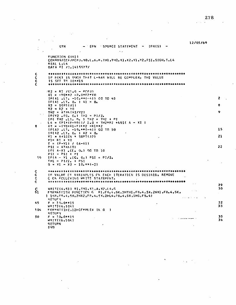
2 7 8
1 2 / 0 5 / 6 * )l»TN - EF N S O U R C E S T A T E M E N T - I F N t S l -
FUNCTION Ol l l l IC 0 M M n N / C C R / P C P J , Y 0 , L , A , R , T H l , T H 2 , X l , X 2 , Y l , Y 2 , P S l , S I G N , T , L 4 REAL Li LA(>AT A p I / ? . I A 1 5 S 2 7 /
C * * * 4 * 4 4 4 * 4 4 4 * * * * * 4 4 * * * * * * * * 4 4 * * * * * + * * 4 4 * * * * * * * * 4 * * 4 * * * * * * * 4 * * * *C I F P ( K 1 IS SUCH TFAT L-RAR HILL BE COMPLEX, THE VALUEC I S SFT TO 1 0 * * 1 5C * 4 * * 4 * * 4 * 4 * * * * * * 4 * 4 * 4 * * * 4 4 * * * * * * * 4 * * * * 4 * 4:4 4 * * 4 4 * 4 * 4 * * 4 * * 4 4 4 4 * * *
■R2 = R1 / M . 0 - PCP JI Al = - Y O * * 2 - ? » 0 * P ? * Y 0 I FC41 . L T , - 1 C . * * < - 4 ) 1 CO TO 45 I F ( A! . I T . 0 . I Al = 0 .X2 = SORT I Al I Y2 = R2 * YO TH2 = A T A M X 2 / Y 2 )I F ( Y2 . FQ. C . I TH2 = P I / 2 .1 F ( TH2 . 1 1 . 0 , ) TH2 = TH2 + PI LA = ( P 1 * C E - Y 0 n / 2 . 0 + TH2*R2 + A0S< A - X2 I
8 A? a - ( Y 0 4 R 1 - P ) * * ? +R1 * * 2I F ( A2 . L T . - 1 0 . * * ( - 4 1 1 GO Tn 50 I F( 42 . L T . C. ) 42 * 0 .XI = A i S l G N * SORT( A ? )Yl = R! + YO T = ( P - Y l ) / ( A—X1)P S I a ATAMTII F ( A- Xl . G E . 0 . 1 GO TO 10 PSI = P S I ♦ PI
10 I F I 4 - XI . E C . 0 . 1 PSI = P I / 2 .THl = P I / 2 . + PS I G = XI - X? - 1 0 . * * ( - 2 )
C 4 4 * 4 * * * 4 4 4 « * * * * * * 4 * * * * * 4 * 4 * 4 4 3 * * 4 * * * * 4 * * * * * * * * * * * * * * * * * * * * * * * * *C I F VALUE CF VARIABLES PN FACE 1 T6RATICN I S OESI REO, REMOVEC C CN FCLLCHIKG WRITE STATEMENT.C 4 4 4 4 4 4 4 4 « 4 4 4 4 * V * 4 4 4 A # 4 4 4 4 4 4 4 4 4 4 4 4 4 * * 4 * 4 * * * * * * * * * * * * * * * * * * * * * 4 < * *
C W R I T E ( 6 , 5 1 I R 1 . T H 1 , X 1 , A , X 2 , L A , G51 FORMAT(15H FUNCTION G R 1 , F R . A , 5 X , 3 H T H 1 , F 8 . A , 5 X , 2 H X 1 , F 0 . 4 , 5 X ,
1 l H A , F B . A , 5 X , 2 H X 2 , F P . A , E X t 2 H L A , F B . A , 5 X , l H G , F 3 . A I RETURN
A5 F b ! 0 , 0 * * 1 5H R I T F ( 6 , 1 C A 1
10A FORMAT! I K . 12FCrMPI .EX IN G IRETURN
5 0 F = 1 . 0 . 0 * 4 15H R I T E C 6 . 1 0 S )RETUPNEND
2
e
9
15
21
22
293 0
323 3
3536
A ppendix III
ELASTIC FR EE T R U N K SHAPE
T he c o m p u te r program described tn th is append ix c om pu tes the cross-sectional
shape for a free elastic t runk . The elasticity m ay 'be non-linear. The logic is similar to th a t
p resen ted in Section 4 .4 .
T he initial inpu t variables are:
a = x co o rd in a te of u p p e r t ru n k a t ta c h m e n t po in t, ft.
b = y co o rd in a te of u p p e r t ru n k a t ta c h m e n t po in t, ft,
p c/p j ~ ratio of cushion pressure to t ru n k pressureo
Pj = t ru n k pressure lb /f t abso lu te
S. = t ru n k length o f e = 0, ft.
T he elastic ity of th e t ru n k is defined by 15 po in ts or less from the tension versus
s train curve and the derivatives of th e end points.
T he in p u t variables fo r the elastic curve are:
NN = n u m b er of po in ts selected from the elastic curve (15 po in ts m axim um )
ARG = value of tension (R * Pj) a t each po in t, lb /f t .
TAB = value of s train (epsilon) a t each p o in t
p o in t f t / f t or in./in.
DV (1) = the reciprocal o f th e derivative of elastic curve at lef t end po in t,
f t / lb
DV (2) = th e reciprocal o f th e derivative of elastic curve a t right end po in t,
f t / lb
This p ro g ra m .is similar t o th e program described in A ppendix I, excep t th e
equa tion to be satisfied in this case is as follows:
279
280
F(R-|) = C — fi {1 + e) = 0
where c = f-| ( R -j) and i! = f 2 (R i )
The program uses the following subroutines:
Function F(R-|) evaluates if —£ ( 1 + e ) = F(R 1 )
Function D F {R ^) evaluates th e derivative of F(R-j).
S ub rou tine RTM1 uses Mueller's Iteration M ethod to converge on the so lu tion of
F{R -j} = 0, once th e so lu tion is b o u n d e d . This sub rou tine is listed in A ppendix I and is n o t
repea ted here.
S u b ro u tin e SPLN1 develops the coeffic ients fo r a th ird degree in terpolating
polynom ial be tw een each pair o f po in ts which specify the elastic curve. These coeffic ients
are s to red in the C m atr ix w hose dim ension is 4 (NN — 1).
S ub rou tine SPLN2 uses th e coeffic ients developed by SPLN1 to in terpo la te fo r
th e value of a t Ri X Pj. The o u tp u t of SPLN2 is a five dimensional vector V with th e
following values:
V (1) = tension or {Ri X Pj)
V (2) = c
V (3) = e '
V (4) = e "
V (5) = key; 1 = value o f V(1) be low the tab le
2 = value o f V{ 1) in the table
3 = value of V (1) above th e tab le
281
These values m ay be p r in ted o u t by removing th e c o m m e n t n o ta t io n f rom th e
write s ta te m e n t above s ta te m e n t 4 0 9 .
T he o u tp u t gives the values o f all inpu t variables, the initial guess fo r R f , th e
n o ta t io n Mueller if the RTM1 sub rou tine was called, and th e final values o f the following
variables:» ■ * •
£, T t , e, R-j, R2 , X0 , y 0 , y lf y2 , 0 2 , and Aj.
282
CIGGESEQTRSF
0 2 / 0 9 / 7 0- EFN SOURCE STATEMENT - I FM{ SI -
COMMON / HAINF / AN, ARG, TAD, C, P J , Vcommon / c c / A , a , p r p j , LCOMMON /OF R / C 1 , C 2 , YO, XC , Y1 , Y2 , TH1 , TH2, SGN 01MFNSICN T A R I 1 5 ) , ARG( 1 5 I , M 9 9 1, C ( 9 9 J , DV( 2 I , VI 5J RFAL 1 1 , L 2 , L . L C . L N . I N M l DATA P | / 2 . 1 4 1 5 9 2 7 /EXTERNAL F
C TOL IS A RELATIVE TCLERANCF GN LRAR . LAN RE CHANGED OYC INSERTING CARO.C * ♦ ♦ « * * * * * * , !
TOL 3 . E - !
CCccc
62
3
31
110
4 0 0
401
4 02
403
404
READ DATA FCR TARLE DEFINING FPS1LGA AS A FUNCTION (IF R*P J AND PASS TO SPLI NF 1N TERP C L A T IC N SLURCJIMINE. R V d l AND OVIP) ARE THE DERIVATIVES AT THE LEFT AND RIGHT F N DP C I MS RESPECTIVELY.
R F A C ( 5 , 6 2 1 A N F O R * A T { 1101 R E A C t 5 , 3 1 ) O V R F A C ( 5 , 3 1 ) I A R G I I ) , 1 = 1 , N N >RFACI 5 , 31 H T A 3 I I ) , I = 1 , N N )FORMAT! BE10 . 2 ICALL SPIN1 I NN, AHG,TAft , 1 , 0 V , C ,R E A M S , 191 A , R , i’C P J , L , P J FORMAT ( 5F1 . 4 , 1 5 1H R l T r I 4 , 4 0 0 I FORMAT I 1 H1 , 4 0 X , 3BH*****
I131( 1H* ) )I CV
FORMAT ( 1 HO, 5X, 37H* * * * *1 19 HOF THE TAPLE * * * * * ,2 / / 1 4X, EH CARG 1 = , E 2 3 . 5 , 10X, DHLARGN = ,
HR1TF I 6 , 4 C 3 ) NN, ( T A I) ( I 1 , ARG I I I , 1 = 1 , NN ) FORMAT I 1 HO, 5X, 14HTA6LE FNTRIES , 1 2 ,
1 I f 1 5 X, 2 F 2 0 . 5 ) )WRITF ( A, 4 C 4 1 A, R, P C P J , L, PJ FORMAT I IHC, 5X, AHA = , E 2 C . 5 , 2CX, 4HR =
WRITE I 6 , 4 0 1 FORMAT I 1 HO, WRITF I 6 , 4 0 2
M )
ELASTIC CO. TR. SHAPE * * * * *
DERIVATIVES AT THE ENO POINTS
E 2 0 . 5 l i f t 1
E 2 0 . 5 , 20X,
4613
2021
22
23
2 4
2 6
3 4
1 7HPCPJ = , E 7 0 . 5 , U 6 X, 4HL E 2 0 . 5 , 20 X, 5HPJ = , E 1 9 . 5 I
FI X SIGN CA SCUARI ROOT.
SGN = 1. CI F ! P 1 * S 0 R I ( A * * 2 f D * * 2 ) / 2 . 9 . L T . LI SGN = - 1.0
C
non
non
n
no
oo
j*
n n
o v
ono
*\j no
n >
nn
283
DIGGCS * 0 2 / 0 9 / 7 0FQTRSH - FFN SCUPCE STATEMENT - I F M S ) -
RO EQUALS I NI TI AL GUESS FOR R l . CAN HE CHANGEC BY INSERTING CARO.
3 5R0 = SORT ( A * * 2 + L ' * * ? 1 * I 1 . 0 ♦ 1 0 . * * ( - £ ) ) / 2 . 3BWRITE ( 6 , 4 0 6 ) RC AO
Of. FORMAT ( 1 HO. 5X, 12 H* * * +* RO = t F 1 6 . A , 2X , 5 H * * * * # / / )RN = RO
CALCULATE K— TH VALUE UE R ANC CBTAIN LE/H IRI
A 0 0 t-B K = 1 , 1 0 0 0
SUBROUTINE r CCMPUTFS LBAR - L I 1 f EPS)
PLN= FIPN1 A6LN = PLN ♦ L
I S R NEGATIVE OR IS LDAP ( R) COMPLEX. I F SO R I K ♦ 1 I = I R I K* 1) ♦ R I K ) ) / 2 ( THI S r XCLFS WHEN R t K ) I S TCC SMALL)
**********
I F I P LN . N E . M . * * 1 5 . AND. RN . GT. 0 . 1 GO TC A A7I Ft K . EQ. 11 Gtl TO 7CRN = [ R N t R N M l 1 / 2 . 0 GO TO 21 FI K . F 0 . 1) GO TO 5
OFT ERM[ NE IF SOLUTICN HAS BEEN BOUNDED. IF SC SET BOUNDS AND CALL ML ELLER POl i TI NE. IF NOT COMPUTE PI K+11 USING NEWTON' S FCR'MJLA.
I F ! SIGN! 1 . , l - L N I . N E . S IGN( 1 . , L - L NH1 )1 GO TO 1 00 LNM1 = LN
****************************** ***+ + **</*+****SUBRnUTINF C F CCMPUTFS I L 9 A R I R H *
OLN = • D FIR N1 6 2R l = RN
TOLERANCE TEST
I F ! ARS I L N- L l . L T . T0L*ABS( L1I GO TC 110 RNM1 = RN
ONd I U1 U‘J
( / / 9 * 5 1 3 * = 2 HIH9 * XO1 * 9* S I 3 * = I H 1 H 9 Z* XQ t * 9 * 9 1 3 * = ZAH5‘ X 0 1 ‘ 9 * 9 1 3 ‘ = l A H 5 ' X t / * 9 * 5 1 3 ‘ = GAH5 1
* XO1 * 9 ’ 9 1 3 * = a X H S * X 0 l ' 9 * 9 1 3 ‘ = Z f c h S * < 0 1 * 9 * 9 1 3 * = 1 f a 3 S * O H t l l V r t b t l dz i i i * i m ' Z A ' u ' o A ' o x ' z a M b 1 5 5 * 9 ) a i m *
1 5 * 9 1 3 * = TVH5 * X3 1 * 5 * 9 1 3 * * S b J 3 9 1*X01 * 5 * 9 1 3 * = V 313 9 *X01 * 5 * 9 1 3 * = hVUHIA ‘ 0 3 1 ) lVriHUd
C V* ( 2 I A 1 ( I 1A ‘ bVO ( A Z t ' 9 ) 3 1 I UH* Z / ( ( U - l ' M ( V-OX ) ) + 1 A * ( V -OX 1 + I
• 2 / ( 2 * * 1 1 1 * 1 1 1 1 1 * • « . ' / < z a * g x i - * z / i z » * Z b * 2 H i j = r vZb * ZHi ♦ l b 0 H I = bVft
V/OX = AOX ( r ( J3d - ’ l l / l b = Zb
d U S( 9 * 5 2 3 2 , * i1U1SH9‘ XS‘ Z1 * IVIlOd <131)101* INI 11VWdU J
9 3 * 1 3 * 1 1 5 1 ( 9 3 1*9151111)' . m i m 13 • ‘si-* n i l 1 3 1
d Ol S( 9 * 5 2 3 2 , * i1U1SH9‘ XS‘ Z1 * IVIlOd d3 1)101 * I h i 11'
(UO i l 01 0 0 13 *53' * o3 I 131
V i ( M31 * 0 3 0 2 * 3 ( l l * N b * I d N b * J ‘ N 3 * t b 1 l b l b 1 3 V 'J( b d 3 1 i r i n H i * OMl 1 1 V A b U d
E i 001*9)31111)1WflJ = IbNU
lh' Jb - )lb Mb = VvDLi
SOI 01 0 0 ( IWNb * 1 0 * No 1.3 1
dUlSI *** * X33J W05 Cib I Hi 1 HVWbOd
6 9 ( 1 1 * 9 ) 3 1 1 1 1 ) 1
3 MM1 N0 D N 3 0 / ( 3 - V3 ) - Nb = Nil
- ( S ) N J l - 1 935J1V1S 3 ObODS N33 - HS blCld0 1 / 6 0 / Z 0 S3901U
frSZ
95
AZl
Cl 1
501
901501
CO (
1101
8 9
on
n o
r> r\
d o
dd
o
c'*n9
2021
C
285
O I G G F S 0 2 / 0 9 / 7 0FTN - EFN S OURCE S T A T E M E N T - I F M S ) -
FUNCTION F { R 11COMMON / PA INF / NN, APG, T A R , C, P J , V COMMON / C C / A , R , P r P J , LCOMMON / OEM/ Cl , C 2 , Y C , X C , Y 1 , Y 2 , T H 1 , 7 H 2 , S G N , PJDEPS0 I MENS 1 EN Cl 9 9 1 , ARG I I S ) , TAB! 15 1 , VI 5 1 DATA PI / 2 . 1A 15 9 2 7 /REAL L
1 f R ( K > I S sue It D A T L —11AR V. IL L GE CCPPLLX, TI E VALUE OF F = LRAR - L IS SET K1 1 0 * * 1 5
+ <.***************♦**** A*SPLN? INTfFFOLATFS FCR EPS AT « 1 * P J .
v m = r i * p jCALL SPLN? I NN, A7G, TAB, C , V )
I F VALIJF CF VARIABLES ON EACH [TERATICN I S DESI RED, REMOVE C ON' THE TNC WRITF STATEMENTS.
WR I T E I S , A 0 9 ) V, R l , P JFORMAT < 1HC, 5 X, 2 7 H .............
1 / / ( 5 E 2 5 . 7 ) jEPS = V ( ? )OEPS = VI 3 )P JO EPS = P J * CEPS
SPLINE OUTPUT
R2 = Rl . / ( 1 . C - P C P J )Cl ~ ( P 1 - R - R 2 ) / AC2 = A / 2 . 0 + I F * * 2 ) / ( 2 . 0 * A ) - I R l * B ) / AASO = ( ? . 0 * R 2 * ? . 0 * C l * C 2 1 * * 2 - K . 0 * C 2 * * 2 ) * I C 1 * * 2 + 1 . 0 ) I F ( ASO . L T . 0 . 0 ) GO Tn 25 SO = SQPTIAS01YO = I - 2 . 0 * | R 2 + C 1 * C 2 M S G N *SCI / ( 2 . 0 M C 1 * * 2 + 1 . 0 1 )
XO = Cl *YC«C2Y 1 = YO t R 1Y 2 = Y0*R2TH2 = ATAN( X0/ Y2I 1 FI Y2 . E C . 0 . 1 TH2 = P I / 2 . C I F I T H ? . L T . 0 . 0 ) TH2 = TH2 + P [PS1 = ATANI I11-Y1 I / ( A-XO) )1FI A-XC) 2 0 , 2 7 , 2 1PSI = P S I « P ITHl = P S I < P 1 / 2 . 0F = R 1 *T H 1 + R 2 * T H ? - L* ( 1 . 0 * EPS)WRITE IN, 2 2 ) R l , R 2 , l H l , T H 2 , Y C , A S 0 , C l , C 2 , P C P J ( X 0 , Y l , Y 2 , A , t l , F
1 3
286
DIGGPS 0 2 / 0 9 / 7 0FTN - EFN SOURCE STATEFFNT - I F M S 1 -
RETUPN?-* P S I = P I / 2 . 0
GO TO 21?*, F = U . 0 + * ISc WR I T E ( 6 , 2 2 ) R l , R 2 , T » U , TH2 , YO, A SO, C I , C 2 , P C P J , XC, Y 1 , Y 2 , A, B , F?? FORMAT!T H O / I T F I E . G ) >
RETURNEND
DIGGESDFRF - EFN SOURCE STATEMENT - I FN( S1
F U N C T I O N O F ( R I )CCMMON / T E R / C l , C ? . Y 0 i X C , Y l , Y 2 , T H l , T H 2 , S G N . P J D F P SC n R P r i N / C C / A . B . P C P J . LR E AL K , LK = 1 . 0 - P C P J0 C 1 = ( K - ) . O I / ( K * A )D C 2 = - P / A X = R l / K 4 C l * C ?Y = C l t t ? * 1 . 0OX = 1 . 0 / K + C 1 * 0 C 2 4 C 2 + I1C115 V = ? . 0 * C 1 * DC II = - S G N * SCR T ( X * * 2 - Y * C 2 * * 2 10 7 = 1 1 . 0 / t ? . 0 * 7 . ) 1 * ( 2 . C * X * 0 X - ( 2 • 0 * Y* C2 * DC2 * C 2 » * 2 * DY) I DYO = ( l . P / Y * * 2 ) * ( - Y * ( DX * 0 7 ) 4 (X+7»«=DY)0 X 0 = C 1 * C Y C ♦ Y 0 * 0 C 1 < 0 C 2 0 Y 1 = DYO 4 I . 0 0 Y 2 * 0 Y 7 4 1 . 0 / K S = P - Y l T = A- X OO S T = ( 1 . 0 / T * * ? ) * t - T * CY1 + S * OX O)0 X C Y 2 = ( l . C / Y 2 * * 2 ) * < Y 2 * 0 X C - X 0 * U Y 2 )O P S I = O S T / t 1 . 0 ♦ C S / 1 1 * * 2 )O T H ? = 0 X C Y 2 / ( 1 . 0 4- 1 X 0 / Y 2 ) * * ? )D T h l = O P S lDF = R l * I D T H 1 + D T H 2 / K ) 4 TUI + T H 2 / K - L + P J O E P SR E T UR NEND
0 2 / 0 9 / 7 0
288
C I G G F S 0 2 / 0 9 / 7 0S P L 1 - EFN S OURCE S T A T E H E N T - I F N 1 S ) -
S U B R O U T I N E S P L N l ( N , X , V , J , D , C , W ) S P L N lD I M E N S I O N X 1 1 ) r Y t 7 > , D 1 2 ) , C ( ) > , W( 1 ) S P L N l
C S P L N lC OVER THE I N T E R V A L X ( M TO X U * l ) i THE I N T E R P O L A T I N G S P L N lC P C I YNC HI A L SP1 N lC Y= Y( I U A ( M * / + f S M ) * Z * * ? + E ( l ) * Z + * 3 S P L I UC Wh ERC 7 = ( X - X l I M / l M I + l ) - X ( I I ) S P L N lC I S U S E D . THE C O E F F I C I E N T S A l l I , G U I AND F i l l ARE COMP UTED S P L N lC RY S ' U . N l AND S T E R E O I N L O C A T l ' C M. C I 3 U - 2 S , C M * I - L ) AND S P L N lC C H M I R E S P E C T I V E L Y . S P L N LC WF I L F V.'CRK I NO I N THE I TH I N T E R V A L , T H E VAR I A 5 L E 0 H I L L S P L N lC R E P R E S E N T C = X ( 1 + 1 ) - X I I ) , AND Y( I I WI L L R E P R E S E N T S P L N lC Y I I t l l - Y l l l S P L N lC S P L N lC S P L N l
0 = X f ? ) - X I 1 ) S P L N lY I = YI 2 I - Y ( 1 1 S P L N lI F I J . F Q . 2 t GO TO 1 0 0 S P L N l
£ SPLNlf I F THE F I R S T TIE R I VA T TVG AT THE END P O I N T S I S G I V E N , S P L N lC A ( l l I S KNOWN i AND THE SECDND E Q U A T I O N l l ECQHES S P L N lC t f F P F L Y R( 1 I + E ( I J =Y I - Q * 0 ( l l . S P L N lC . ----------------------------------S P L N l
C l I ) = 9 * 0 ( 1 I S P L N lC I 2 1 = 1 . 0 S P L N lW I 2 1 = Y 1 - C I I I S P L N lOQ TD 2 0 0 S P L N l
C, ----------------------------------------------------------------------------------------------- SP l . NLC I T THE SCC. CNJ D E R I V A T I V E AT T I E END P O I N T S I S G I V E N S P L N lC R l I J I S KNOWN, THE S F CDND E Q U A T I O N B E C OME S S P L N lC A l l | * F I n = Y I - C . 5 * 0 * G * D t I I . D U R I N G THF S O L U T I O N OF S P L N lC THE 3 N - A F O L A T I C N S . A l R I L L OE KE P T I A. C E L L C I 2 ) S P L N lC I N S T E A D OF C l I I TO R E T A I N THE T R 1 0 1 AGCAAL FORM OF THE S P L N lC C O E F F I C I E N T M A T R I X . S P L N lC SPLNl1 0 0 C ( 2 1 = 0 . C S P L N l
W ( 2 1 = Q . 5 * G * Q * n i 1 I S P L N l2 0 0 M = N - 2 S P L N l
I F ( R . L E . O ) GO TO 2 5 0 S P L N lc S P L N lC U P P E R T R I A N G U L A R I Z A T I O N OF THE T R I C I A G C N A L S Y S T E M OF S P L N lC E Q U A T I O N S FOR THE C O E F F I C I E N T MA T R I X F O L L O WS — S P L N Lc ---------------------------------------------------------------------------------------------------------------------------------------------------- S P L N l
on 300 I = l , M S P L N lA l = C S P L N lQ = X ( H 2 I - X l l + l l S P L N lM = A I / O S P L N l0 ( 3 + 1 ) = - H / ( 2 . 0 - C < 3 * 1 - 1 1 I S P L N lW ( 3 * I l = l - T I - H M * I - l l l / ( 2 . 0 - C I 1 M - 1 I I S P L N lC 1 3 * I U 1 = - H + H / I H - C l 3 * 1 I I S P L N lW ( 3 + I ♦ 1 1 = ( Y I - W I 3 * I I ) / ( H - C ( 3 * I ) 1 S P L N lY I =YI U 2 I - YI 1 + 1 1 . S P L N lC ( 3 * 1 + 2 > = 1 . C / ( I . 0 - C ( 3 * I + 1> I S P L N l
. 3 9 0 W 1 3 * I + R ) = ( Y I - W t 3 * I + l l l / t 1 . 0 - C 1 3 * ! + 1 M S P L N lr ’------------------ S P L N l
289
OI GGFS 0 2 / 0 9 / 7 0Si’ Ll - EFN SDURCE STATEMENT - I F N t S l -
C F f A - 1 1 I S DETERMINED DIRECTLY FRCM THF LAST EQUATION SPLNlC Ol l T / I NED AnOVE, AN 11 THE F I R S T CR SECOND DERI VATI VE SPLNlC VALUE GIVEN AT THE END POI NT. SPLNlc ------------------------------------------------------------------------------------------------------------------------------------ SPLNl3 5 9 I F I J . F Q . l t GO TO APO SPLNl
C l 3 * N - 3 ) = I 0 * 9 * D( 2 1 / 2 . O - E I 3* A - A ) J / I 3 . 0 - C I 3 + N - A I I SPLNlGO TO 5(19 SPLNl
A09 C I 3 * N - 3 ) = ( 0 * 0 ( 2 ) - Y I - V i ( 3*N- A I t / t 2 . O- CI 3*N- A1 ) SPLNL5 0 0 M O *N—6 SPLNl
I F I P . l C . D t GO TO TOC SPLI I lc ----------------------------------------------------------------------------------------------------------------------------------------------- SPLNlC PACK SOLUTION FCR ALL C O E F F I C E M S EXCEPT SPLNlC A l l ! AND P t l ) FL’LLORS— SPLNlc SPLNl
0 0 6 0 0 1 1 = 1 , M SPLNl1 = M — I 1 + 3 SPLNl
6 0 0 C I I ) = W ( l > - C ( I t * CI I H » SPLNl7 0 0 I F I J . E O . l t GO TO 60C SPLNlc ----------------------------------------------------------------------------------------------------------------------------------------------- SPLNlC I F THE SECOND DERI VATI VE I S GIVEN AT THE END POI NTS, SPLNlC A I 1 t CAN NOW OF CCU PUT ED FROM H E KNDViA VALUES OF SPLNlC O i l ) AND F i l l . THEN A l l ) AND 13(11 ARE PUT INTO THEIR SPLNlC PROPER PLACES IE THE C ARRAY. SPLNlC SPLNl
C < 1 I =YI 2) - Y( 1 ) - M 2 t - C I 3) SPLNlC ( 2 I = WI 2 1 SPLNlRFTURN SPLNl
R O D C ( 2 | = W t 2 1 - C I 3 ) SPLNlRETURN SPLNlEND SPLNl
290
f l l G G F S 0 2 / 0 9 / 7 0S P I N ? - F F N SOURCE S TAT EMENT - I F N I S I -
CCr.c
0 I S Tt -E S I Z E OF THE I N T E R V A L CENT AI M U G V ( l l .
7 I S 4 L I N E A R TRA NSF ITRMAT I CN OF THE I NT ERVAL f N T O t c , l ) a n d I S THE VAI UATL E F CR WHI CH THE C O E F F I C I E N T S WERE COMPUTED HY S P L N l .
00 0 = X I l l - X I 1 - 1 )i = i v i n - x ( i - i »i/oV(?l = CI7*CC’«‘l -3> «C n* l-A ))*Z *C (3*I-5n* / + Y ( l - n V t 3 I — ( I 3 .*7*CI1*1-31*?.0*C<3 * I- A I ) *7+C( 3*1-51 I /O v m = I6 .*M CM *I-3) *2.0+01 3* I-A II /(C+Q)RETURNEND
S U B R O U T I N E S P L N 2 ( N » X , Y , C . V ) D I M E N S I O N X I I I , Y ( I I , C ( 1 I , V < E l V I S ) = ? . 0 L IH = N - 1
DE T E R MI NE I N WHI CH I N T E R V A L THE I N D E P E N D E N T VAR I A B L E i V f U , L I E S .
0 0 10 I = 2 , L I M1 F( V(. l I .1 T . XI I I 1 On TO 70t =NI F ( V U ) . O T . X I N I I VI 5 I * 3 . flGO TO 3 0I F I VII I . L T - X I 1 I I V I 51 = 1 . 0
A p p e n d ix IV
T R U N K C O N S T R U C T IO N
T h e t r u n k sec t io n w as m ad e o f a n y lo n -h y p a lo n m ateria l. T h e d im e n s io n s o f th e
p iece o f m ateria l, b e fo re fab r ica t io n o f th e l iu n k , w ere 5 9 -1 /2 inches by 3 3 inches.
A p p ro x im a te ly fo u r inches o f th e leng th w as used fo r a t ta c h in g th e t ru n k t o th e m odel
s t ru c tu re ; th e unp ressu r ized leng th o f th e t r u n k b ecam e 5 5 -1 /2 inches. O ne-ha lf inch o f the
m ateria l was fo lded over and sew n along each edge o f t h e t ru n k t o increase th e s tiffness of
t h e edge (see F igure IV-1). A s tr ip o f t r u n k m ateria l 1 -1 /2 inches w ide was sew n a long e i th e r
edge o f t h e t r u n k t o a c t as a sealing flap . W hen th e t r u n k w as in fla ted , p ressu re inside th e
t r u n k pressed th e f lap against th e walls, resu lting in a n effec tive seal. A n y lon s tr ing inside
t h e fo ld o f th e f lap was used as a d raw str ing to s lightly decrease t h e leng th o f th e free edge
o f th e flap . T h e final w id th o f t h e te s t sp ec im en w as 3 2 inches.
T h e t r u n k was p e r fo ra te d w ith 192 holes o f 5 / 1 6 inch d iam e te r . T h e ho les w ere
a rranged in 8 row s o f 2 4 holes e a ch , as sh o w n in F igure IV -1 . T h e c en te r l in e o f th e o u ts id e
row o f holes was lo ca ted 31 inches f ro m th e o u ts id e a t t a c h m e n t p o in t . A 1 /1 6 inch
d ia m e te r ho le was p u n c h e d a t each o f t h e p ressu re t a p lo ca t ions ind ica ted in F igure IV-1.
T h e pressure ta p s u sed to m easu re s ta t ic p ressu re on th e o u ts id e o f t h e t ru n k are
s h o w n in F igure IV-2. A 2-inch leng th o f 1 /8 inch O.D . c o p p e r tu b in g w as f lared a n d
f la t te n e d a t o n e en d to give a th in f la t flange. T h e tu b in g was b e n t , as sh o w n , an d c e m e n te d
t o t h e t r u n k over t h e 1 /1 6 inch ho le w i th a p re p u n c h e d squa re p iece o f t r u n k m ateria l.
P lastic tu b in g was c o n n e c te d t o t h e c o p p e r tu b in g , a n d c e m e n te d to th e t r u n k fo r a s h o r t
d is tance . T h u s , m o t io n o f t h e c o p p e r tu b in g an d a c o rre sp o n d in g d e f le c t io n o f th e t r u n k
s u rfa c e w ere p rev e n ted . T h e o u ts id e su rfa c e o f th e t r u n k had n o th in g p ro tru d in g to d is ru p t
t h e f low , an d th e area in w h ich th e p ressu re w as m easu red w as a s m o o th c o n t in u a t io n o f t h e
t r u n k c o n to u r .
291
292
Trunk
1 1 / 4
0 - Pressure Tap LocationJet Pattern
T R U N K S P E C I M E N DETAILS
F I GUR E IV-1
293
T R U N K PRESSURE T A P S
FIGURE I V - 2
2.3-r
rr, 1.3-
o 60 9030 ISO120 150 210
pj < p * * g )
TRUNK M ATERIAL E L O N G A T IO N
FIGURE IV -3
294
A section of th e t ru n k material was tested fo r tension-elongation in a tensile tes t
machine. T he results w ere used to p red ic t th e e longation of th e t ru n k a t various pressure
levels. Figure IV-3 show s the resulting pressure-elongation curve for th e t ru n k under test.
E quation (4-1) was used to relate th e tension to the t ru n k pressure. All results presented in
C hap ter 6 w ere co rrec ted fo r t ru n k elongation.
A p p en d ix V
D E T E R M IN A T IO N O F FLOW LEA K A G E
T h e f low leakage in th e m odel was m easured as a fu n c t io n o f t ru n k pressure to
enab le co rrec tions to be m ade t o su b seq u e n t f low calculations.
Before th e ho les had been pun ch ed in th e t ru n k , the t ru n k was a t ta c h e d to th e
m odel an d inflated. In th is m anner , a m easu rem en t of th e flow leakage be tw een th e t ru n k
sec tion and th e walls o f th e m odel was m ade. A 1.2 inch orifice was used fo r f low
m easu rem en t because th e f low rate was q u ite low. T he f low leakage m easu rem en ts are
p resen ted in Figure V-1.
295

0,4296
0.3
80 . 12040 160O
Pj (psfg)
L E A K A G E V A R I A T I O N W I T H T R U N K PRES S URE
F I G U R E V - l
A ppendix VI
C O E FFIC IE N T OF DISC H A RG E O F T R U N K
T he coeff ic ien t of discharge o f th e t ru n k (Cx ) is the f low coeffic ien t fo r th e entire
orifice area o f the t ru n k (ap , in the absence of cushion pressure.
With the movable f loo r rem oved from the m odel, the air gap betw een the t ru n k
and th e b o t to m of th e m odel was sufficiently large th a t no restric tion was p resen ted to
t ru n k f low . Thus, th e pressure on th e outside of the t ru n k was equal to a tm ospheric
pressure. T h e system was ope ra ted th ro u g h o u t an ex ten d ed range o f t ru n k pressures, 10-140
psf, and th e da ta required for f low calculations were recorded.
T h e ideal rate of flow th rough the holes would be th a t p red ic ted by a
co m b in a tio n of the laws o f conservation o f energy and mass.
T o m ake th e results applicable to su b seq u en t runs w hen a cushion exists under
pa rt of th e t ru n k , Cx was p lo tted as a func t ion of Px /Pj. Px is defined as th e average o f th e
absolu te cush ion pressure and a tm ospheric pressure.
7(VI-1)
T h e coeff ic ien t of discharge o f the t ru n k is herein defined as th e ratio of actual jet
flow, w hen the re is no cushion present, t o th e ideal jet flow.
(VI-2)
297
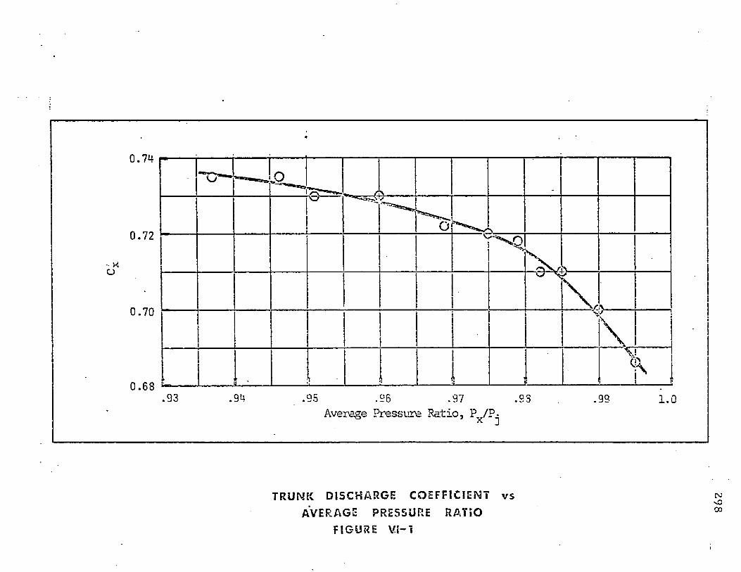
0 . 7 4
0 . 7 2
0 . 7 0
0 . 6 8.9 3 .9 9 1.0
Average Pressure Ratio, P„/P*
T R U N K D I S C H A R G E C O E F F I C I E N T v s
AVERAGE PRESSURE R A T I O
FIGURE VI-1
29
8
299-
R E F E R E N C E S
1. T . D. Earl, A F F D L -T R -6 7 -3 2 , " A i r C ush ion Landing G ear Feasib ili ty S tu d y ," Bell
A e ro sy s te m s C o m p a n y , Mar 1967.
2. T. D. Earl a n d R. H. C o o p e r , A F F D L -T R -G 3 -1 2 4 , " A i r C ush ion Landing G ear fo r
A i rc ra f t , " Bell A e ro sy s te m s C o m p a n y , A ugust 1968 .
3. C. S ta u ffe r , A F F D L -T R -6 9 -3 2 , " G r o u n d F ligh t T e s t R ep o r t o f A ir C ush ion
Landing G ear (L A -4 ) ," Bell A e ro sy s te m s C o m p a n y , A p r 1969 .
4 . D. J . Perez a n d H. K. Brewer, A F F D L -T M -6 9 -1 1 -F D F M , " A ir C ush ion Landing
G ear Sk id Brake H eat T ra n s fe r S t u d y , " A F F ligh t D ynam ics L a b o ra to ry , Feb
1969.
5. K, H. Digges a n d D. J . Perez, " A i r C ush ion Landing S y s tem fo r S T O L A irc ra f t ,”
A F F ligh t D ynam ics L a b o ra to ry , V /S T Q L T e c h n o lo g y and P lanning C onfe rence ,
2 5 Sep 1969 .
6. D. J. Perez, " Im p l ic a t io n s o f A ir C ush ion Landing S ys tem on S T O L A i r c r a f t / ' A F
Fligh t D y n am ics L a b o ra to ry , 1969 .
7. J. T a y lo r , "A ll t h e W orld 's A i r c r a f t , " M cGraw-Hill Publish ing Co., 1964 .
8. A. H arting , " A L i te ra tu re Survey on th e A e ro d y n a m ic s o f A ir C ush ion V eh ic les ,"
A G A R D R e p o r t No. 565 , 1969 .
9. T . D. Earl, " A G A R D o g ra p h on G ro u n d E ffec t M ach ines ," A G A R D o g ra p h No. 6 7 ,
Ja n 1962 ,
300
10. J . C. M. F ros t, " F lo w P henom ena of th e Focused A nnu la r J e t , Sym pos ium on
G ro u n d E ffec t P h e n o m en a ," P rince ton University, O c t 1959.
11. J . C. M. F ros t, " T h e Canadian C o n tr ib u t io n to th e G round Cushion S to ry ,”
C anadian A eronau tica l Jo u rn a l , O c to b e r 1961 .
12. R. K. G reif and W. H. T o lhu rs t , " Large Scale Wind Tunnel Tests of a C ircular
P lanform A ircraft w ith a Peripheral J e t fo r Life, T h ru s t and C o n tro l ," NA SA TN
D-1432, Feb 1963.
13. J. B. Chaplin , " T h e D eve lopm en t o f a Multi-Cell Plenum C o n c e p t ," A IA A Paper
64-188, May 1964.
14. W. Z. S tepniew ski, "P e rfo rm a n c e Possibilities o f Subson ic Airplanes Taking-O ff
and Landing on th e G ro u n d C u sh ion ," S ym p o s iu m on G round Effect P henom ena ,
P r ince ton University , O c t 1959 .
15. W. Z. S tepn iew ski, " T h e Subson ic V TO L an d G E TO L in Perspective ," A erospace
Engineering, O c t 1959.
16. S. M o n tu o ro , "P re l im inary Results of an Experim enta l Investigation o f V arious
A n n u la r J e t C onfigura tions in G round E ffec t ," A tt i del VG Congresso
A e ro n a u tico E uropeo , Venezia, Sep 1962.
17. W. Z. S tepniew ski and F. J . McHigh, "P e rfo rm a n c e C onsidera tions o f G ro u n d
Effec t Take-O ff and Landing (G ETO L) T ra n sp o r t A irc ra f t ," N ew Y ork A cad em y
of Sciences, Vol 107, A rtic le 1, Mar 1963.
301
18. W. Z. S tepn iew sk i , e t al., " R e sea rc h P rogram t o D e te rm in e th e Feasibili ty and
P o ten tia l o f th e G ro u n d E ffec t T ake-O ff an d Landing (G E T O L ) C o n f ig u ra t io n ,"
Vol 1, US A rm y T ra n s p o r t R esearch C o m m a n d , T C R E C T echn ica l R e p o r t 62-63 .
19. C onvair 's " G E T O L F l ig h t ," Feb 1963 .
20 . W. D. R eeder a n d F. W. M cD onald , " G E T O L A ircra ft , A R esearch S ta tu s
R e p o r t ,” In s t i tu te of A erospace Sciences, IAS Paper 6 2 -1 8 2 , Ju n 1962 .
21 . Ph. Po isson -Q u in ton , "T w o-D im ens iona l S tu d ie s o f a G ro u n d E ffec t P la t fo rm ,"
S y m p o s iu m on G ro u n d E ffec t P h e n o m en a , P r in c e to n U nivers ity , O c t 1959 .
22 . Ph. P o isson-Q uin ton , " In f lu e n c e o f th e P ro x im ity o f th e G ro u n d on th e
A e ro d y n a m ic C harac te r is tic s o f V /S T O L A irc ra f t Using J e t s , " A G A R D o g ra p h 46 ,
S y m p o s iu m on V /S T O L A ircraft , Part II, J u n 1960 .
23 . K. Dau, "C h a ra c te r is t ic s o f a R ec tangu la r Wing w ith a Peripheral J e t in G ro u n d
E f fe c t ," Part I, U nivers ity of T o r o n to , In s t i tu te o f A erophysics , U T IA TN -56, Sep
1961 .
24 . J . M. Davis, "C h a ra c te r is t ic s o f R ec tangu la r Wing w ith a Peripheral J e t in G ro u n d
E f fe c t ," P a r t II, U nivers ity of T o r o n to , In s t i tu te of A erophysics , U TIA T N -59 ,
M ay 1962.
25. K. Dau, e t al., A e ro d y n a m ic s o f a R ec tan g u la r Wing w ith a Peripheral J e t fo r A ir
C ush ion T ake-O ff a n d L an d in g ," C anad ian A e ro n a u tic s a n d S pace Jo u rn a l , M ar
1965 .
302
26 . A. W. C ar te r a n d L. H. Person , " In v es tig a tio n o f th e F ree-F ligh t C haracte ris tics
a n d H andling Q ualit ies o f a G ro u n d E ffec t M ach in e ," NA SA T N -D -3 8 8 5 , A pr
1967 .
27. " N e w D ev e lo p m en ts in A ir C ush ion V eh ic les ," Hovering C ra f t and H ydro fo il .
28 . R. M cLeavy, " J a n e 's S u rface S k im m e r S y s t e m s / ' 1 9 67 -68 1st Ed ition S a m p so n
Low, M ars ton , L o n d o n , 1967 .
29. R. M cLeavy, " J a n e 's All T h e W orlds Surface S k im m e r S y s te m s ," 6 9 th E d it ion .
30 . G. D. Bochler, " A e ro d y n a m ic T h e o ry o f th e A n n u la r J e t , " In s t i tu te o f A erospace
Sciences, IAS R e p o r t 59-77 , J a n 1959 .
31 . H. R. C hap lin and B. S te p h e n s o n , "P re l im in ary S tu d y o f th e Hovering
P e r fo rm a n c e o f A n n u la r J e t V ehic les in P ro x im ity to th e G r o u n d ," David T a y lo r
M odel Basic, DTMB A ero R e p o r t 9 4 7 , Sep 1958 .
32 . T . S tra n d , Inviscid, " in c o m p re s s ib le F low T h e o ry o f S ta tic , Peripheral J e ts in
P ro x im i ty t o t h e G r o u n d ," Jo u rn a l o f t h e A erospace Sciences, J a n 1961.
33. F. F. Ehrich , " T h e C ur ta in J e t , " J o u rn a l o f th e A ero sp ace Sciences, Nov 1961.
34 . M. J. C ohen , "P e r ip h e ra l J e ts in P ro x im i ty o f th e G r o u n d ," J o u rn a l o f A pp lied
M echanics, Dec 1966 .
35 . T . P. Bligh, " T h e P o ten tia l F low S o lu t io n o f t h e Peripheral J e t o f an A ir C ush ion
V ehicle , A pp licab le t o all H / t R a t io s ," U nivers i ty o f W itw a te rs ran d R e p o r t 3 0 ,
Dec 1965.
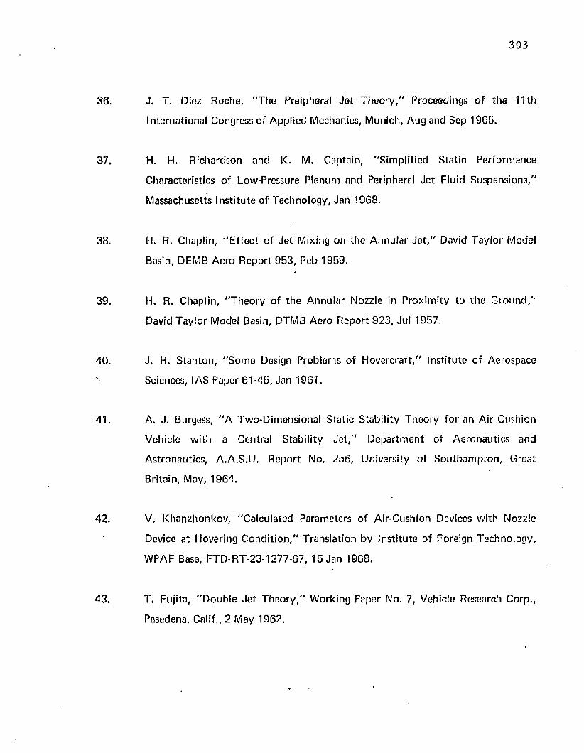
303
36. J. T. Diez Roche, "T he Preipheral J e t T h e o ry ," Proceedings o f the 11th
International Congress of Applied Mechanics, Munich, Aug and Sep 1965.
37. H. H. R ichardson and K. M. Captain, "Sim plified S ta tic Perform ance
Characteristics o f Low-Pressure P lenum and Peripheral J e t Fluid Suspensions,"
Massachusetts Insti tu te of Technology, Jan 1968.
38. I t. R. Chaplin, "E ffe c t o f J e t Mixing on th e A nnu lar J e t , " David Tay lor Model
Basin, DEMB A ero R eport 953 , Feb 1959.
39. H. R. Chaplin, "T h e o ry of th e Annular Nozzle in P roxim ity to the Ground,'*
David T ay lo r Model Basin, DTMB Aero R eport 923 , Jul 1957.
40. J . R. S tan ton , "S o m e Design Problem s of H overcraft ," Institu te of Aerospace
Sciences, IAS Paper 61-45, Jan 1961.
41. A. J. Burgess, "A Tw o-D im ensionat S ta tic Stability T heory fo r an Air Cushion
Vehicle w ith a Central Stability J e t , " D epa r tm en t of A eronau tics and
Astronautics , A.A.S.U. R eport No. 256, University of S o u th a m p to n , Great
Britain, May, 1964.
42. V, K hanzhonkov , "C alcu lated Param eters o f Air-Cushion Devices with Nozzle
Device a t Hovering C o n d i t io n ," T ransla tion by Insti tu te of Foreign T echnology,
WPAF Base, FTD -R T-23-1277-67, 15 Jan 1968.
43. T. Fujita, "D o u b le J e t T h e o ry ," Working Paper No. 7, Vehicle Research Corp.,
Pasadena, Calif., 2 May 1962.
J a c k B. Esgar an d W. C. M organ, "A n a ly t ica l S tu d y o f S o f t Land ings on
Gas-Filled Bags," N A SA T R R-75, Mar 1960.
D. M. G o rm a n , Lt U SA F, " E q u i l ib r iu m C harac te r is tic s of a D is tr ib u te d Periuheia!
J e t , " Thesis , A F In s t i tu te o f T e c h n o lo g y , S chool o f Engineering , W-P A F B , O h io ,
Mar 1970 .
S. D. C o n te , " E le m e n ta ry N um erical A na ly s is ," M cGraw-Hill. 19G5, p 66 , p 922 .
L K. S p ink , "P rinc ip les an d P ractices o f F low M eter E n g in e e r in g / ' (N in th
E d ition ) , F o rb o ro , M assachusetts : F o r o b o ro C o m p a n y , 1967 .
ACME R esearch C o m m it te e o n F lu id M eters, " F lu id M eters, T h e i r T h e o r y and
A p p l ic a t io n ," (F if th E d it ion ) , N ew Y o rk : A m erican S o c ie ty o f M echanical
Engineers, 1959.
L. S. Han, "P ressu re D is tr ib u t io n in a Channel w ith P orous W alls ," A F T D L
Technica l R e p o r t (To be pub lished).
C. L. S ta u ffe r , "W ate r O p e ra t io n s and O verland B raking T es t R e p o r t o i Air
C ush ion Landing S y s tem (L A -4 ) ," Techn ica l R e p o r t A F F D L -T R -6 9 -1 2 5 ,
T e x t r o n 's Bell A e ro sy s te m s Co., Dec 1969 .
Related Documents


