System Hardware Manual A50-035028-001 GE ISSUE 2.0 SV9100 ®

Welcome message from author
This document is posted to help you gain knowledge. Please leave a comment to let me know what you think about it! Share it to your friends and learn new things together.
Transcript

System Hardware Manual
A50-035028-001 GEISSUE 2.0
SV9100®

NEC Corporation reserves the right to change the specifications, functions, orfeatures at any time without notice.
NEC Corporation has prepared this document for use by its employees andcustomers. The information contained herein is the property of NEC Corporationand shall not be reproduced without prior written approval of NEC Corporation.
Dterm, NEAX and UNIVERGE are registered trademarks of NEC Corporation andElectra Elite is a registered trademark of NEC America, Inc. Windows is aregistered trademark of Microsoft Corporation. AT&T, the AT&T logo and all otherAT&T marks are trademarks of AT&T Intellectual Property and/or AT&T affiliatedcompanies. Pentium is a trademark or registered trademark of Intel Corporation orits subsidiaries in the United States and other countries. Bluetooth is a registeredtrademark owned by Bluetooth SIG Inc. and is licensed to NEC Corporation ofAmerica. All other brand names and product names referenced in this documentare trademarks or registered trademarks of their respective companies.
Copyright 2014-2015
NEC Corporation

PREFACE
GENERAL INFORMATION Congratulations! You have purchased the NEC UNIVERGE SV9100 System.
The feature-rich UNIVERGE SV9100 Communication Platform provides over 200 features including Computer Telephony Integration, Least Cost Routing, Automatic Call Distribution, ISDN-BRI Voice Trunks, ISDN-PRI Voice Trunks, Voice over Internet Protocol, and many others.
The UNIVERGE SV9100 system provides what the customer needs today, and as business expands the system can be expanded to grow as well.
The UNIVERGE SV9100 system has a set of manuals that provides all the information necessary to install and support the system. This preface describes these manuals.
THIS MANUAL This manual contains detailed instructions to install the UNIVERGE SV9100 chassis, Blades, Multiline Terminals, and optional equipment in the following chapters.
Regulatory
This chapter provides important regulatory information.
Chapter 1 – Introduction to SV9100
This chapter provides an overview of the UNIVERGE SV9100 system.
Chapter 2 – SV9100 System Specifications
This chapter contains detailed specifications for the SV9100 system and should be carefully reviewed by the technician before installing the system.
Chapter 3 – Installing the SV9100 Chassis
This chapter contains the information necessary for installing the SV9100 chassis. The technician should become familiar with this section before starting installation.
Chapter 4 – Installing the SV9100 Blades
This chapter contains instructions for installing the blades in the UNIVERGE SV9100 chassis.

Chapter 5 – Installing DT Series Digital and IP Multiline Terminals
This chapter provides information about the UNIVERGE SV9100 system digital and IP terminals in addition to the single line telephones, cordless telephones and wireless telephones.
Chapter 6 – Installing SV9100 Cordless Telephones
This chapter provides information regarding cordless telephones that can be used in conjunction with the UNIVERGE SV9100 system.
Chapter 7 – Installing SV9100 Optional Equipment
This chapter provides information for installing optional equipment, such as PGDADs, background music, door boxes, DSS consoles, external paging as well as other handsets, recording devices and adapters on the UNIVERGE SV9100 digital and IP telephones.
SUPPORTING DOCUMENTS Other manuals in the set are described below.
Documents supporting the SV9100 system include:
UNIVERGE SV9100 Features and Specifications Manual
This manual describes each available feature for the SV9100 system.
UNIVERGE SV9100 General Description Manual
This manual contains general information about the system features, configuration and standards. This overview of the SV9100 system is useful when presenting information to potential customers.
UNIVERGE SV9100 Programming Manual
This manual contains all programming instructions for the SV9100 system.
UNIVERGE SV9100 PC Programming Manual
This manual describes the operation of the PCPro program for the SV9100 system. This program is a user-friendly Windows application that allows the user to program and configure features of the SV9100 system from the PC environment.

System Hardware Manual i
TABLE OF CONTENTS
Regulatory
Chapter 1 Introduction to SV9100
Section 1 General Information ................................................................................. 1-1
Section 2 Equipment List ......................................................................................... 1-5
Chapter 2 SV9100 System Specifications
Section 1 General Information ................................................................................. 2-1
Section 2 System Block Diagram ............................................................................ 2-1
Section 3 Maximum System Capacities.................................................................. 2-5
3.1 Trunk/Port/Channel Capacities ....................................................... 2-5
3.2 System Chassis Capacities........................................................... 2-10
3.3 Blade Capacities ........................................................................... 2-12
Section 4 Licensing ................................................................................................ 2-17
Section 5 Power-Based Calculator Chart ............................................................. 2-27
Section 6 System Requirements and Specifications........................................... 2-31
6.1 Cabling .......................................................................................... 2-31
6.2 Power Requirements..................................................................... 2-33
6.2.1 Power Supply Specifications........................................................2-34
6.2.2 Power Supply Consumption.........................................................2-35
6.3 Environmental Conditions ............................................................. 2-35
6.3.1 Temperature and Humidity ..........................................................2-35
6.4 Outside Line Types ....................................................................... 2-36
6.5 Transmission, Network, and Control Specifications ...................... 2-38
6.5.1 Transmission................................................................................2-38

ii Table of Contents
Issue 2.0
6.5.2 Network........................................................................................ 2-38
6.5.3 Control ......................................................................................... 2-38
6.6 Dialing Specifications .................................................................... 2-39
6.6.1 Dial Pulse Address Signaling ...................................................... 2-39
6.6.2 Dual-Tone Multifrequency (DTMF) Address Signaling ................ 2-39
6.6.3 External Equipment Connection .................................................. 2-40
6.6.4 Music Source for Music on Hold via Chassis............................... 2-40
6.6.5 Music Source for Station Background Music via ACI .................. 2-40
6.6.6 External Paging (Audio)............................................................... 2-40
6.6.7 External Tone Ringer/Night Chime Output .................................. 2-40
6.6.8 SMDR Output .............................................................................. 2-41
6.6.9 PC Connection............................................................................. 2-41
6.6.10 Relay Contact .............................................................................. 2-41
6.7 Battery Backup.............................................................................. 2-41
6.7.1 System Backup (Optional) ........................................................... 2-41
6.7.2 Memory Backup........................................................................... 2-41
6.8 Weights and Dimensions .............................................................. 2-42
6.8.1 Tone Patterns .............................................................................. 2-47
6.8.2 Multiline Terminal LED Flash Patterns ........................................ 2-47
Section 7 Traffic Capacity ...................................................................................... 2-50
Chapter 3 Installing the SV9100 Chassis
Section 1 General Information................................................................................. 3-1
Section 2 Site Preparation and MDF/IDF Construction ......................................... 3-1
2.1 Precautionary Information: .............................................................. 3-1
2.2 Surveying the Customer Site .......................................................... 3-2
2.3 Selecting the Best Location for Proper Installation ......................... 3-2
2.3.1 Selecting the Chassis Installation Site........................................... 3-2
2.3.2 Selecting a Permanent MDF Location ........................................... 3-3
2.3.3 Selecting a Site for Installing the Telephones................................ 3-3

System Hardware Manual iii
Issue 2.0
2.4 Constructing the Main Distribution Frame (MDF)............................ 3-3
2.5 Power Failure Transfer.................................................................... 3-4
2.6 Fax CO Branch Connection ............................................................ 3-5
Section 3 Installing the Chassis .............................................................................. 3-5
3.1 Unpacking the Equipment ............................................................... 3-5
3.2 Before Installation............................................................................ 3-5
3.3 Installing the 19” (CHS2UG) Chassis.............................................. 3-6
3.3.1 Installing the 19” Controlling Chassis.............................................3-8
3.3.2 Installing Expansion Blades in the 19” Chassis (Optional) ............3-9
3.3.2.1 Connector Pin-Out on the GPZ-BS10/GPZ-BS11 ..................3-10
3.3.2.2 Install the GPZ-BS10 Expansion Base Blade in the CHS2UG Con-trolling Chassis .......................................................................3-10
3.3.2.3 Install the GPZ-BS11 Expansion Blade in the CHS2UG Expansion Chassis ...................................................................................3-13
3.3.2.4 Connect the Controlling and Expansion Chassis....................3-17
3.3.3 Install Grounding on 19” Chassis.................................................3-19
3.3.4 Install Grounding on Multiple 19” Chassis (Optional)...................3-19
3.3.5 Install AC Power Cords on 19” Chassis.......................................3-20
3.3.6 Install AC Power Cords on Multiple 19” Chassis (Optional).........3-21
3.3.7 Install Additional Blades 19” Chassis...........................................3-21
3.3.8 Apply Power to the 19” Chassis...................................................3-21
3.4 Installing the 9.5” Gateway (CHS2UG GW) and Base (CHS2UG B) Chassis.......................................................................................... 3-22
3.4.1 Install Grounding on 9.5” Gateway or Base Chassis ...................3-23
3.4.2 Install AC Power Cord 9.5” Gateway or Base Chassis ................3-23
3.4.3 Install Additional Blades 9.5” Gateway or Base Chassis .............3-23
3.4.4 Apply Power to the 9.5” Gateway or Base Chassis .....................3-23
3.5 Installing the 9.5” Base (CHS2UG B) and Expansion (CHS2UG E) Chassis.......................................................................................... 3-24
3.5.1 Connecting the 9.5” Base and Expansion Chassis......................3-25
3.5.2 Installing Expansion Blades in the 9.5” Base and Expansion Chassis (Optional) .....................................................................................3-29
3.5.2.1 Connector Pin-Out on the GPZ-BS10/GPZ-BS11 ..................3-30

iv Table of Contents
Issue 2.0
3.5.2.2 Install the GPZ-BS10 Expansion Base Blade in the CHS2UG B Controlling Chassis .............................................3-30
3.5.2.3 Install the GPZ-BS11 Expansion Blade in the CHS2UG B Expan-sion Chassis ...........................................................................3-33
3.5.2.4 Connect the Controlling and Expansion Chassis....................3-35
3.5.3 Installing Grounding on 9.5” Base and Expansion Chassis......... 3-36
3.5.4 Install Grounding on Multiple 9.5” Base and Expansion Chassis 3-37
3.5.5 Install AC Power Cord on 9.5” Base and Expansion Chassis ..... 3-37
3.5.6 Install AC Power Cord on Multiple 9.5” Base and Expansion Chassis.....................................................................................................3-37
3.5.7 Install Additional Blades in the 9.5” Base and Expansion Chassis..........................................................................................................3-37
3.5.8 Applying Power to the 9.5” Base and Expansion Chassis........... 3-37
Section 4 Wall Mounting the Chassis ................................................................... 3-38
4.1 Wall Mounting the 19” (CHS2UG) Chassis ................................... 3-38
4.1.1 CHS2UG Chassis Wall Mount Installation ................................ 3-38
4.2 Wall Mounting the 9.5” Gateway (CHS2UG GW) and Base (CHS2UG B) Chassis.................................................................... 3-46
4.2.1 Option 1 – Wall Mounting the 9.5 inch Base (CHS2UG B) Chassis........................................................................................................3-46
4.2.1.1 Wall Mounting the 9.5” Base (CHS2UG B) and Expansion (CHS2UG E) Chassis .............................................................3-54
4.2.2 Option 2 – Wall Mounting the 9.5 inch Base (CHS2UG B) Chassis ........................................................................................................3-58
4.2.2.1 Wall Mounting the CHS2UG B without the CHS2UG B Small Batt Box..........................................................................................3-59
4.2.2.2 Wall Mounting the CHS2UG B with the CHS2UG B Small Batt Box................................................................................................3-63
Section 5 Floor Mounting the Chassis.................................................................. 3-68
5.1 Floor Mounting the 19” (CHS2UG) Chassis.................................. 3-68
5.1.1 CHS2UG Chassis Installation...................................................... 3-68
5.1.2 Multiple CHS2UG Chassis Installation ........................................ 3-71
Section 6 Stand Mounting the Chassis................................................................. 3-72
6.1 Stand Mounting the 19” (CHS2UG) Chassis................................. 3-72
6.1.1 CHS2UG Chassis Installation...................................................... 3-72
6.1.2 Multiple CHS2UG Chassis Installation ........................................ 3-75

System Hardware Manual v
Issue 2.0
6.2 Stand Mounting the 9.5” CHS2UG B Chassis............................... 3-78
Section 7 Rack Mounting the Chassis .................................................................. 3-82
7.1 Rack Mounting the 19” (CHS2UG) Chassis .................................. 3-82
7.2 Rack Mounting the 9.5” Base (CHS2UG B) and Expansion (CHS2UG E) Chassis.................................................................... 3-84
Section 8 Battery Connection ................................................................................ 3-87
8.1 Installing the Internal Batteries 19” (CHS2UG) Chassis................ 3-87
8.2 Installing the External Batteries 19” (CHS2UG) Chassis .............. 3-92
8.2.1 Floor Mounting the CHSG LARGE BATT BOX............................3-93
8.2.2 Battery Installation .......................................................................3-94
8.2.3 CHSG LARGE BATT BOX to CHS2UG Connection ...................3-98
8.2.4 CHSG LARGE BATT BOX Fuse Replacement .........................3-101
8.3 Installing the CHS2UG B SMALL BATT BOX on the 9.5” CHS2UG B Chassis........................................................................................ 3-104
8.3.1 CHS2UG B SMALL BATT BOX Installation...............................3-104
8.3.2 CHS2UG B SMALL BATT BOX Fuse Replacement..................3-110
8.4 Installing the External Batteries (CHSG LARGE BATT BOX) to the 9.5” Gateway (CHS2UG GW) or Base (CHS2UG B) Chassis............ 3-111
8.4.1 CHSG LARGE BATT BOX Installation ......................................3-111
8.4.2 CHSG LARGE BATT BOX to 9.5” Gateway (CHS2UG GW) or Base (CHS2UG B) Chassis Connection .............................................3-112
8.4.3 CHSG LARGE BATT BOX Fuse Replacement .........................3-113
Section 9 Power Supply ....................................................................................... 3-113
Section 10 Remove and Install Cooling Fan......................................................... 3-114
10.1 CHS2UG Chassis........................................................................ 3-114
10.1.1 Remove Cooling Fan .................................................................3-114
10.1.2 Install Cooling Fan .....................................................................3-115
Chapter 4 Installing the SV9100 Blades
Section 1 General Information ................................................................................. 4-1
1.1 Slot Locations.................................................................................. 4-1

vi Table of Contents
Issue 2.0
Section 2 Installation ............................................................................................... 4-4
2.1 Installation and Safety Precautions................................................. 4-4
2.2 Installing an Extension or Trunk Blade............................................ 4-5
2.2.1 Installing the Blades ...................................................................... 4-5
2.2.2 Order of Installing Extension Blades.............................................. 4-6
2.2.3 Order of Installing Trunk Blades .................................................... 4-7
2.2.3.1 Installing GCD-COT( ), GCD-4DIOPB, GCD-4ODTB or GCD-2BRIA Blades ..................................................................4-7
2.2.3.2 Installing GCD-PRTA (PRI/E1) Blades .....................................4-8
2.3 Remove an Extension or Trunk Blade ............................................ 4-8
2.4 Uninstalling a Blade Slot Through Software.................................... 4-9
2.5 Blade Capacities ............................................................................. 4-9
2.6 Powering Up the SV9100 System................................................... 4-9
2.6.1 Performing a Cold Start ................................................................. 4-9
2.6.2 Performing a Hot Start ................................................................. 4-10
2.6.3 Resetting the System................................................................... 4-10
2.6.3.1 Initial Programming.................................................................4-10
2.6.3.2 Port Defaults ...........................................................................4-11
2.6.3.3 Setting Up Extension Circuit Types ........................................4-11
2.6.3.4 Saving Your Configuration......................................................4-11
2.6.3.5 Backing Up/Restoring a Database..........................................4-12
2.6.4 Performing a Software Upgrade .................................................. 4-13
Section 3 Common Control Blades....................................................................... 4-15
3.1 GCD-CP10 (SV9100 Central Processing Unit) ............................. 4-15
3.1.1 Description................................................................................... 4-16
3.1.2 Installation.................................................................................... 4-19
3.1.2.1 Battery Installation and Removal ............................................4-19
3.1.2.2 GPZ-IPLE Daughter Board Installation...................................4-21
3.1.2.3 SD-A1/SD-B1 Installation .......................................................4-21
3.1.2.4 Background Music (BGM) or Music on Hold (MOH)...............4-21
3.1.3 Switch Settings ............................................................................ 4-22
3.1.4 LED Indications............................................................................ 4-23

System Hardware Manual vii
Issue 2.0
3.1.5 Connectors...................................................................................4-24
3.2 GPZ-IPLE (Voice over IP Daughter Board)................................... 4-27
3.2.1 Description ...................................................................................4-27
3.2.2 Installation....................................................................................4-28
3.2.3 Switch Settings ............................................................................4-28
3.2.4 LED Indications............................................................................4-29
3.2.5 Connectors...................................................................................4-30
Section 4 Station Blades ........................................................................................ 4-33
4.1 GCD-8DLCA/GCD-16DLCA (Digital Station Interface) ................. 4-33
4.1.1 Description ...................................................................................4-34
4.1.2 Installation....................................................................................4-34
4.1.3 LED Indications............................................................................4-34
4.1.4 Connectors...................................................................................4-35
4.2 GPZ-8DLCB (Digital Station Daughter Board) .............................. 4-37
4.2.1 Description ...................................................................................4-37
4.2.2 Installation....................................................................................4-38
4.2.3 GPZ-8DLCB Daughter Board Cable Connection.........................4-38
4.3 GCD-4LC( )/GCD-8LC( ) (4-Port/8-Port Single Line Interface) ..... 4-40
4.3.1 Description ...................................................................................4-40
4.3.2 Installation ...................................................................................4-41
4.3.3 LED Indications............................................................................4-42
4.3.4 Connectors...................................................................................4-42
4.4 GPZ-4LC( )/GPZ-8LC( ) (4-Port/8-Port SLI Daughter Board) ....... 4-44
4.4.1 Description ...................................................................................4-44
4.4.2 Installation....................................................................................4-45
4.4.3 Connectors...................................................................................4-45
4.5 GCD-LTA (Dterm/SLT Combination) .............................................. 4-47
4.5.1 Description ...................................................................................4-47
4.5.2 Installation....................................................................................4-48
4.5.3 LED Indications............................................................................4-49
4.5.4 Connectors...................................................................................4-50

viii Table of Contents
Issue 2.0
Section 5 Trunk Blades .......................................................................................... 4-51
5.1 GCD-4COT( ) (4 Loop and Ground Start Interface) ...................... 4-51
5.1.1 Description................................................................................... 4-52
5.1.2 Installation.................................................................................... 4-52
5.1.3 LED Indications............................................................................ 4-53
5.1.4 Connectors .................................................................................. 4-53
5.2 GPZ-4COT( ) (4 Loop and Ground Start Interface Daughter Board) ...........................................................................................................4-55
5.2.1 Description................................................................................... 4-55
5.2.2 Installation.................................................................................... 4-56
5.2.3 Connectors .................................................................................. 4-56
5.3 GCD-2BRIA (2 Basic Rate Interface)............................................ 4-58
5.3.1 Description................................................................................... 4-58
5.3.2 Installation.................................................................................... 4-59
5.3.3 LED Indications............................................................................ 4-60
5.3.4 Connectors .................................................................................. 4-61
5.4 GPZ-2BRIA (2 Basic Rate Interface Daughter Board) .................. 4-62
5.4.1 Description................................................................................... 4-62
5.4.2 Installation.................................................................................... 4-63
5.4.3 Connectors .................................................................................. 4-63
5.5 GCD-4DIOPB (DID/OPX Interface)............................................... 4-65
5.5.1 Description................................................................................... 4-65
5.5.2 Installation.................................................................................... 4-66
5.5.3 LED Indications............................................................................ 4-66
5.5.4 Connectors .................................................................................. 4-67
5.6 GCD-PRTA (PRI/T1/E1 Interface) ................................................ 4-68
5.6.1 Description................................................................................... 4-68
5.6.2 Installation.................................................................................... 4-70
5.6.3 LED Indications............................................................................ 4-70
5.6.4 Connectors .................................................................................. 4-73
5.7 GCD-4ODTB (4-Port Tie Line Interface Blade)............................. 4-74

System Hardware Manual ix
Issue 2.0
5.7.1 Description ...................................................................................4-75
5.7.2 Installation....................................................................................4-75
5.7.3 LED Indications............................................................................4-76
5.7.4 Connectors...................................................................................4-76
5.7.5 Connections .................................................................................4-78
Section 6 Optional Blades...................................................................................... 4-80
6.1 GCD-VM00 (Voice Mail and Server) ............................................. 4-80
6.1.1 Description ...................................................................................4-80
6.1.2 Installation....................................................................................4-81
6.1.3 LED Indications............................................................................4-82
6.1.3.1 Active LED – Green ................................................................4-82
6.1.3.2 Busy LED – Red .....................................................................4-83
6.1.3.3 Application LED – Red/Green (Dual Color) ............................4-83
6.1.3.4 CompactFlash Card Activity LED – Red.................................4-83
6.1.4 Connectors...................................................................................4-83
6.1.4.1 RS-232 Interface.....................................................................4-83
6.1.4.2 DB9 to 6-pin Modular RS-232 Adapter ...................................4-84
6.1.4.3 RS-232 Serial Cable (DTE) ....................................................4-84
6.1.4.4 RS-232 Serial Cable (DCE) ....................................................4-85
6.1.4.5 USB Interface .........................................................................4-85
6.1.4.6 VGA Display Interface ............................................................4-85
6.1.4.7 10 Base-T/100 Base-TX Ethernet Interface............................4-85
6.2 GCD-PVAA (Packet Voice Application)......................................... 4-87
6.2.1 Description ...................................................................................4-87
6.2.2 Installation....................................................................................4-88
6.2.3 Switch Settings ............................................................................4-88
6.2.4 LED Indications............................................................................4-89
6.2.5 Connectors...................................................................................4-89
6.3 GCD-RGA (Application Gateway) ................................................. 4-90
6.3.1 Description ...................................................................................4-90
6.3.2 Installation....................................................................................4-92
6.3.3 Switch Settings ............................................................................4-92

x Table of Contents
Issue 2.0
6.3.4 Status LEDs................................................................................. 4-93
6.3.5 LED Indications............................................................................ 4-93
6.3.6 Connectors .................................................................................. 4-94
6.4 GCD-ETIA (Gigabit PoE Switch)................................................... 4-95
6.4.1 Description................................................................................... 4-95
6.4.2 Installation.................................................................................... 4-96
6.4.2.1 Stacking Architecture..............................................................4-96
6.4.2.2 GCD-CP10 IP Address Assignment .......................................4-97
6.4.2.3 Group Formation.....................................................................4-97
6.4.2.4 Port Number Determination ....................................................4-97
6.4.2.5 Unmanaged Switch Functions ................................................4-98
6.4.3 LED Indications............................................................................ 4-98
6.4.4 Connectors .................................................................................. 4-98
Section 7 Cabling and MDF Connection............................................................... 4-99
7.1 Connection Requirements............................................................. 4-99
7.2 Cabling Precautions ...................................................................... 4-99
7.3 Wiring Between the Chassis and the MDF ................................... 4-99
7.3.1 Chassis Cables............................................................................ 4-99
7.3.2 Outside Lines............................................................................. 4-103
Chapter 5 Installing DT Series Digital and IP Multiline Terminals
Section 1 General Description................................................................................. 5-1
Section 2 DT300/DT400 Series Digital Multiline Terminals ................................. 5-14
2.1 DT300 Series Digital Multiline Terminals ...................................... 5-14
2.1.1 DTL-2E-1 (BK) TEL ..................................................................... 5-14
2.1.2 DTL-6DE-1 (BK) TEL................................................................... 5-15
2.1.3 DTL-12E-1 (BK) TEL ................................................................... 5-16
2.1.4 DTL-8LD (BK)/(WH) TEL............................................................. 5-17
2.1.5 DTL-12BT-1 (BK) TEL ................................................................. 5-18
2.1.6 DTL-12D-1 (BK)/(WH) TEL.......................................................... 5-19
2.1.7 DTL-12PA-1 (BK) TEL................................................................. 5-20

System Hardware Manual xi
Issue 2.0
2.1.8 DTL-24D-1 (BK)/(WH) TEL ..........................................................5-21
2.1.9 DTL-32D-1 (BK)/(WH) TEL ..........................................................5-22
2.2 DT400 Series Digital Multiline Terminals ...................................... 5-23
2.2.1 DTZ-2E-3 (BK) TEL .....................................................................5-23
2.2.2 DTZ-6DE-3 (BK) TEL...................................................................5-24
2.2.3 DTZ-12D-3 (BK)/(WH) TEL..........................................................5-25
2.2.4 DTZ-24D-3 (BK)/(WH) TEL..........................................................5-26
2.2.5 DTZ-8LD-3 (BK)/(WH) TEL..........................................................5-27
Section 3 DT700/DT800 Series IP Multiline Terminals......................................... 5-28
3.1 DT700 Series IP Multiline Terminals ............................................. 5-28
3.1.1 ITL-2E-1 (BK) TEL .......................................................................5-28
3.1.2 ITL-6DE-1 (BK) TEL.....................................................................5-29
3.1.3 ITL-8LDE-1 (BK) TEL...................................................................5-30
3.1.4 ITL-8LD-1 (BK)/(WH) TEL............................................................5-31
3.1.5 ITL-12D-1 (BK)/(WH) TEL............................................................5-32
3.1.6 ITL-12/24CG-3 (BK) TEL .............................................................5-33
3.1.7 ITL-12/24DG-3 (BK) TEL .............................................................5-34
3.1.8 ITL-12PA-1 (BK) TEL...................................................................5-35
3.1.9 ITL-24D-1 (BK)/(WH) TEL............................................................5-36
3.1.10 ITL-32D-1 (BK/WH) TEL ..............................................................5-37
3.1.11 ITL-320C-1 (BK) TEL/ITL-320C-2 (BK) TEL ................................5-38
3.2 DT800 Series IP Multiline Terminals ............................................. 5-39
3.2.1 ITZ-8LD-3 (BK) TEL.....................................................................5-39
3.2.2 ITZ-12D-3 (BK)/(WH) TEL ...........................................................5-40
3.2.3 ITZ-12/24CG-3 (BK)/(WH) TEL....................................................5-41
3.2.4 ITZ-12/24DG-3 (BK)/(WH) TEL....................................................5-42
3.2.5 ITZ-24D-3 (BK)/(WH) TEL ...........................................................5-43
3.2.6 ITZ-8LDG-3 (BK)/(WH) TEL.........................................................5-44
Section 4 Install Multiline Terminals ..................................................................... 5-45
4.1 Connecting the DT300/DT400 Series Multiline Terminal to the System.......................................................................................................5-45

xii Table of Contents
Issue 2.0
4.1.1 Connecting the Handset .............................................................. 5-45
4.1.1.1 Handset Connection DT300 ...................................................5-45
4.1.1.2 Handset Connection DT400 ...................................................5-45
4.1.2 Connecting the Line Cord ............................................................ 5-46
4.1.2.1 Line Cord Connection DT300 .................................................5-46
4.1.2.2 Line Cord Connection DT400 .................................................5-47
4.2 Applying Power to the DT700/DT800 Multiline Terminal .............. 5-49
4.3 Connecting the DT700/DT800 Series IP Multiline Terminal to the Net-work and PC.................................................................................. 5-50
4.4 Adjusting the LCD on the Multiline Terminal ................................. 5-52
4.5 Installing Line Key Kit (12LK-L KIT) .............................................. 5-52
4.5.1 Installing the 12LK-L KIT ............................................................. 5-52
4.5.2 Configuring the Digital Telephone for the Correct Number of Line Keys............................................................................................. 5-57
4.5.3 Configuring the IP Telephone for the Correct Number of Line Keys .......................................................................................................5-58
4.6 Installing the Directory Card on the Multiline Terminal.................. 5-60
4.7 Removal and Replacement of the Numbered Keypad.................. 5-61
4.7.1 Removing the Numbered Keypad ............................................... 5-62
4.7.2 Installing the Numbered Keypad.................................................. 5-63
4.8 Removal and Replacement of the BS( )-L Kit (Ten Key Kit) ........ 5-64
4.8.1 Remove the BS( )-L Kit............................................................... 5-64
4.8.2 Install the BS( )-L Kit................................................................... 5-65
4.8.3 Configuring the Digital Telephone for the Ten Key Kit................. 5-67
4.8.4 Configuring the IP Telephone for the Ten Key Kit ....................... 5-68
4.9 Install the Sticker-Braille-L KIT...................................................... 5-69
4.10 Adjusting the Height on the Multiline Terminal.............................. 5-71
4.11 Removing or Installing the Tilt Legs on the Multiline Terminal...... 5-72
4.11.1 Remove Tilt Legs......................................................................... 5-72
4.11.2 Install Tilt Legs............................................................................. 5-73
4.12 Wall Mounting the Multiline Terminal ............................................ 5-75
4.12.1 Wall Mounting a Multiline Terminal using the Base Plate............ 5-75

System Hardware Manual xiii
Issue 2.0
4.12.1.1 Adjusting the Hanger Hook.....................................................5-75
4.12.1.2 Wall Mounting the Multiline Terminal ......................................5-76
4.12.1.3 Removing the Multiline Terminal from the Wall Mounted Base Plate........................................................................................5-77
4.12.1.4 Wall Mounting the Base on a Wall Plate.................................5-78
Section 5 Multiline Terminals Optional Equipment ............................................. 5-79
5.1 DT Series Terminal Options .......................................................... 5-79
5.2 DT Series Optional Terminal Equipment....................................... 5-80
5.2.1 8LK-L UNIT (BK/WH)...................................................................5-80
5.2.1.1 Installing the 8LK-L UNIT........................................................5-81
5.2.2 8LKD (LD)-L UNIT (BK/WH) ........................................................5-83
5.2.2.1 Installing the 8LKD (LD)-L UNIT .............................................5-83
5.2.3 8LKI (LD)-L UNIT (BK/WH)..........................................................5-87
5.2.3.1 Installing the 8LKI (LD)-L UNIT...............................................5-87
5.2.4 DCL-60-1/DCZ-60-2 CONSOLE (BK/WH)...................................5-91
5.2.4.1 Installing the DCL-60-1/DCZ-60-2 CONSOLE........................5-92
5.2.5 LCD (BL)-L UNIT (BK/WH) ..........................................................5-96
5.2.6 LCD (BL)-Z UNIT (BK/WH) ..........................................................5-96
5.2.7 PANEL( )-L UNIT ........................................................................5-97
5.2.8 WM-L UNIT ..................................................................................5-98
5.2.8.1 Mount Multiline Terminal on Wall using WM-L UNIT ..............5-98
5.2.8.2 Mount Multiline Terminal on Wall Plate using WM-L UNIT...5-102
5.2.9 DSS WM-L UNIT........................................................................5-106
5.2.9.1 Mount DCL-60-1/DCZ-60-2 CONSOLE on Wall using DSS WM-L UNIT .....................................................................................5-106
5.2.9.2 Mount DCL-60-1/DCZ-60-2 CONSOLE on Wall Plate using DSS WM-L UNIT...........................................................................5-107
Chapter 6 Installing SV9100 Cordless Telephones
Section 1 General Description ................................................................................. 6-1
Section 2 Bluetooth Cordless Handset................................................................... 6-1
2.1 Bluetooth Cordless Handset (BCH) Interface.................................. 6-1
2.2 Selecting a Location ........................................................................ 6-3

xiv Table of Contents
Issue 2.0
2.3 Controls and Indicators ................................................................... 6-4
2.4 Installing the Bluetooth Cordless Handset ...................................... 6-6
2.4.1 Installing the Bluetooth Handset Cradle ........................................ 6-6
2.4.2 Wall Mounting the Bluetooth Cradle ............................................ 6-12
2.4.3 Remove and Replace Handset Battery ....................................... 6-15
Section 3 Bluetooth Hub Adapter.......................................................................... 6-16
3.1 Bluetooth Hub Adapter (BHA) Features........................................ 6-16
3.1.1 Installing the BHA-L UNIT ........................................................... 6-16
3.1.2 Pairing a Bluetooth Device and Multiline Terminal (Bluetooth In-stalled) ......................................................................................... 6-18
3.1.2.1 Accessing the Bluetooth Device Setup Screen ......................6-18
3.1.2.2 Entering a PIN Code...............................................................6-18
3.1.2.3 Pairing.....................................................................................6-18
3.1.2.4 Connecting the Paired Device ................................................6-19
3.1.2.5 Unpairing ................................................................................6-19
3.1.2.6 Visibility Setting.......................................................................6-19
3.1.2.7 BT Information ........................................................................6-20
Section 4 Optional Headsets ................................................................................. 6-20
4.1 Dterm ® USB Wireless Headset ..................................................... 6-20
4.1.1 Installing the Base Unit ................................................................ 6-21
4.1.2 Installing the PerSonoCall Software ............................................ 6-21
4.1.3 Charging the Headset Battery ..................................................... 6-21
4.1.4 Initial Setup .................................................................................. 6-21
4.1.5 Using the Headset ....................................................................... 6-21
4.2 Headsets Used with Dterm ® Telephones ...................................... 6-22
4.2.1 NEC Dterm ® Headset (MX250).................................................... 6-22
4.2.2 NEC Dterm ® Cordless Phone Headset (M175) ........................... 6-23
4.2.3 NEC Dterm ® NEC Polaris SupraPlus™ ....................................... 6-23
4.2.4 NEC Dterm ® NEC Polaris Mirage ®............................................. 6-24
4.2.5 NEC Dterm ® NEC Polaris TriStar ®............................................. 6-24
4.2.6 NEC Dterm ® NEC Polaris Encore ® ............................................ 6-25

System Hardware Manual xv
Issue 2.0
Chapter 7 Installing SV9100 Optional Equipment
Section 1 General Information ................................................................................. 7-1
Section 2 PGDAD ..................................................................................................... 7-1
2.1 Using a PGDAD .............................................................................. 7-1
2.2 LED Indications ............................................................................... 7-2
2.3 Setting up PGDAD Connections ..................................................... 7-2
Section 3 Background Music ................................................................................. 7-10
3.1 Installing Background Music.......................................................... 7-10
Section 4 Door Box ................................................................................................. 7-10
4.1 Installing a Door Box ..................................................................... 7-10
Section 5 External Paging ...................................................................................... 7-14
5.1 External Page................................................................................ 7-14
5.2 Installing an External Page System............................................... 7-14
Section 6 External Paging and Door Box/Page Relays ....................................... 7-16
6.1 External Page Relays.................................................................... 7-16
6.2 Door Box /External Page Relay Contacts ..................................... 7-16
6.2.1 Connecting a Contact Relay Device to a Door Box/External Page Re-lay ................................................................................................7-16
Section 7 External Recording System/External Ringer....................................... 7-17
7.1 External Recording System or External Ringer............................. 7-17
7.2 Installing an External Recording System or External Ringer......... 7-18
7.3 Programming................................................................................. 7-19
Section 8 Music Sources........................................................................................ 7-21
8.1 Music on Hold................................................................................ 7-21
8.2 Installing External Music on Hold .................................................. 7-21
Section 9 Night Mode Selection............................................................................. 7-24
9.1 Night Mode Selector Switch .......................................................... 7-24

xvi Table of Contents
Issue 2.0
9.2 Connecting a Night Mode Selector Switch.................................... 7-24
Section 10 Telephone Labeling ............................................................................... 7-24
10.1 DESI Printer Sheets ...................................................................... 7-24
10.1.1 Removing the Faceplate.............................................................. 7-25
Section 11 Telephone Adapters .............................................................................. 7-26
11.1 Using Adapters.............................................................................. 7-26
11.2 In-line Power Adapter (ILPA-R)..................................................... 7-26
11.2.1 Conditions.................................................................................... 7-27
11.2.2 Installation.................................................................................... 7-28
11.3 ADA-L UNIT .................................................................................. 7-30
11.3.1 ADA-L UNIT Switch Settings ....................................................... 7-30
11.3.2 Installing the ADA-L UNIT............................................................ 7-32
11.3.3 ADA-L UNIT Connection.............................................................. 7-34
11.3.3.1 ADA-L UNIT Connection for Recording Only..........................7-34
11.3.3.2 ADA-L UNIT Connection for Sending Recorded Calls to the Tele-phone......................................................................................7-34
11.3.3.3 Send a Startup (REMOTE) Signal to the Recorder ................7-35
11.4 APR-L UNIT .................................................................................. 7-36
11.4.1 APR-L UNIT Switch Settings ....................................................... 7-37
11.4.2 Installing the APR-L UNIT............................................................ 7-37
11.5 PSA-L (BK) UNIT / PSA-L (WH) UNIT .......................................... 7-40
11.5.1 Installing the PSA-L Adapter ....................................................... 7-41
11.5.2 Using the PSA-L Adapter............................................................. 7-48
11.6 Gigabit Adapter (GBA-L UNIT)...................................................... 7-49
11.6.1 Installing the GBA-L UNIT ........................................................... 7-49
11.6.2 GBA-L UNIT Connection ............................................................. 7-57
11.6.3 LED Display ................................................................................. 7-57
Section 12 Power Failure Telephones .................................................................... 7-58
12.1 Power Failure ................................................................................ 7-58
12.2 Connector Pin-Outs on COIU Blade for Power Failure Circuits .... 7-59
System Hardware Manual xvii
Issue 2.0
12.3 Installing the Power Failure Telephones ....................................... 7-59
Section 13 IP Video Doorphone............................................................................... 7-60
13.1 Connection Image ......................................................................... 7-61
13.1.1 Local Setting (Web Setting) .........................................................7-61
13.1.2 System Connections ....................................................................7-62
13.2 IP Video Doorphone and Options.................................................. 7-62
13.3 Location of Controls ...................................................................... 7-65
13.4 Before Installing the IP Video Doorphone ..................................... 7-66
13.4.1 Precautionary Information............................................................7-66
13.4.2 Installation Information.................................................................7-66
13.4.3 General Precautions ....................................................................7-69
13.4.4 Site Requirements .......................................................................7-69
13.4.5 Powering On the IP Video Doorphone.........................................7-70
13.5 Installation ..................................................................................... 7-70
13.5.1 Connect a Door Unlock Device to the IP Video Doorphone ........7-70
13.5.2 Adjusting the Camera Angle ........................................................7-73
13.5.3 Installing the IP Video Doorphone ..............................................7-75
13.5.4 Installing the IP Video Doorphone Using a Wall Mount Bracket (IP-3WW-CDH BRACKET SET) ........................................................7-76
13.5.5 Installing the IP Video Doorphone Using a Wall Cover Set (IP-3WW-CDH WALL COVER SET) .................................................7-78

xviii Table of Contents
Issue 2.0

SV9100 System Hardware Manual xix
LIST OF FIGURES
Chapter 1 Introduction to SV9100
Figure 1-1 Simplified SV9100 System (9.5” Gateway and Base) Connectivity ...............................1-2
Figure 1-2 Simplified SV9100 System (9.5” Base and Expansion) Connectivity ............................1-3
Figure 1-3 Simplified SV9100 System (19”) Connectivity ...............................................................1-3
Chapter 2 SV9100 System Specifications
Figure 2-1 SV9100 System Block Diagram .....................................................................................2-4
Figure 2-2 19” Controlling and Expansion Chassis .........................................................................2-7
Figure 2-3 Connecting the DLC Using Twisted 2-Pair Cable ........................................................2-31
Chapter 3 Installing the SV9100 Chassis
Figure 3-1 CHS2UG Chassis (Front View) ......................................................................................3-7
Figure 3-2 CHS2UG Chassis (Rear View) ......................................................................................3-7
Figure 3-3 19” Controlling Chassis – Guides Slot 1 ........................................................................3-8
Figure 3-4 Installing the GCD-CP10 Blade .....................................................................................3-8
Figure 3-5 GCD-CP10 Blade Installed ............................................................................................3-8
Figure 3-6 GPZ-BS10 Components ..............................................................................................3-10
Figure 3-7 GPZ-BS10 Expansion Bay in Controlling Chassis .......................................................3-11
Figure 3-8 Open Base Chassis Cover ...........................................................................................3-11
Figure 3-9 GPZ-BS10 Blade Guides .............................................................................................3-12
Figure 3-10 Installing GPZ-BS10 Blade in Expansion Bay .............................................................3-12
Figure 3-11 GPZ-BS10 Blade Installed ...........................................................................................3-13
Figure 3-12 GPZ-BS10 Installed (Cover Closed) ............................................................................3-13
Figure 3-13 GPZ-BS11 Components ..............................................................................................3-13
Figure 3-14 GPZ-BS11 Expansion Bay in Expansion Chassis .......................................................3-14
Figure 3-15 Open Expansion Chassis Cover ..................................................................................3-14
Figure 3-16 GPZ-BS11 Blade Guides .............................................................................................3-15
Figure 3-17 Installing GPZ-BS11 Blade in Expansion Chassis .......................................................3-15
Figure 3-18 GPZ-BS11 Blade Installed ...........................................................................................3-16

xx List of Figures
Issue 2.0
Figure 3-19 GPZ-BS11 Installed (Cover Closed) ........................................................................... 3-16
Figure 3-20 19” Expansion Chassis Interface Units ....................................................................... 3-17
Figure 3-21 System Expansion Cabling ......................................................................................... 3-18
Figure 3-22 Chassis Grounding Lug ............................................................................................... 3-19
Figure 3-23 19” Chassis Grounding Lug (Multiple-Chassis) ........................................................... 3-20
Figure 3-24 Install the AC Power Cord ........................................................................................... 3-20
Figure 3-25 Install 19” AC Power Cords (Multiple-Chassis) ........................................................... 3-21
Figure 3-26 9.5” Chassis (Front View) ............................................................................................ 3-22
Figure 3-27 9.5” Chassis (Rear View) ............................................................................................ 3-23
Figure 3-28 9.5”Base and Expansion (Combined) Chassis ............................................................ 3-24
Figure 3-29 Removing Backboard Cover ....................................................................................... 3-25
Figure 3-30 Installing the Expansion Bracket ................................................................................. 3-26
Figure 3-31 Remove Expansion Chassis Cover ............................................................................. 3-26
Figure 3-32 Connecting the Base and Expansion Chassis ............................................................ 3-27
Figure 3-33 Securing the Expansion Chassis to the Expansion Bracket ........................................ 3-27
Figure 3-34 Install Expansion Chassis Cover ................................................................................. 3-28
Figure 3-35 Installing Reinforcement Bracket ................................................................................. 3-28
Figure 3-36 GPZ-BS10 Components .............................................................................................. 3-30
Figure 3-37 CHS2UG B Expansion Bay ......................................................................................... 3-31
Figure 3-38 Installing the GPZ-BS10 .............................................................................................. 3-32
Figure 3-39 Completing the Installation .......................................................................................... 3-32
Figure 3-40 GPZ-BS11 Components .............................................................................................. 3-33
Figure 3-41 CHS2UG B Expansion Bay ......................................................................................... 3-33
Figure 3-42 Installing the GPZ-BS11 .............................................................................................. 3-34
Figure 3-43 Completing the Installation .......................................................................................... 3-34
Figure 3-44 System Expansion Cabling ......................................................................................... 3-35
Figure 3-45 9.5” Chassis (Rear View) ............................................................................................ 3-36
Figure 3-46 Wall Mount Spacing Guide (19” Chassis) ................................................................... 3-39
Figure 3-47 Install Wall Mount Brackets with Screws ..................................................................... 3-40
Figure 3-48 Securing Metal Fittings to Chassis with Screws .......................................................... 3-41
Figure 3-49 Secure Metal Fitting to Upper Wall Mount Bracket with a Screw ................................ 3-42
Figure 3-50 Secure Metal Fitting to Lower Wall Mount Bracket with Screws ................................. 3-43
Figure 3-51 Attach Cable Support Bracket to Lower Wall Mount Bracket ...................................... 3-44
Figure 3-52 Attachment Locations of Cable Support Bracket ......................................................... 3-45

SV9100 System Hardware Manual xxi
Issue 2.0
Figure 3-53 Wall Mount Positioning for 9.5” Base/Expansion Chassis ...........................................3-46
Figure 3-54 Wall Mount Spacing Guide (9.5” Chassis) ...................................................................3-47
Figure 3-55 Anchor Bolt from Wall (9.5” Chassis) ...........................................................................3-48
Figure 3-56 Align Bracket on Wall (9.5” Chassis) ...........................................................................3-48
Figure 3-57 Install Upper Bracket (9.5” Chassis) ............................................................................3-49
Figure 3-58 Optional Small Battery Box (9.5” Chassis) ...................................................................3-50
Figure 3-59 Install Lower Bracket (9.5” Chassis) ............................................................................3-50
Figure 3-60 Install Lower Bracket (9.5” Chassis) ............................................................................3-51
Figure 3-61 Washer Location (9.5” Chassis) ...................................................................................3-51
Figure 3-62 Install the Shaft (9.5” Chassis) .....................................................................................3-52
Figure 3-63 Install the Stopper (9.5” Chassis) .................................................................................3-52
Figure 3-64 Chassis Installed (9.5” Chassis) ..................................................................................3-53
Figure 3-65 Wall Mount Spacing Guide (Base and Expansion Chassis) ........................................3-54
Figure 3-66 Anchor Bolt from Wall (9.5” Chassis) ...........................................................................3-55
Figure 3-67 Remove Support Bracket (Base and Expansion Chassis) ...........................................3-55
Figure 3-68 Install Support Bracket (Base and Expansion Chassis) ...............................................3-56
Figure 3-69 Chassis Installed (Base and Expansion Chassis) ........................................................3-57
Figure 3-70 Wall Mount Spacing Guide (9.5” Chassis) ...................................................................3-58
Figure 3-71 Anchor Bolt from Wall (9.5” Chassis) ...........................................................................3-59
Figure 3-72 Wall Mounting Brackets (Option 2) ..............................................................................3-59
Figure 3-73 Install Upper Bracket (Option 2) ...................................................................................3-60
Figure 3-74 Install Lower Bracket (Option 2) ...................................................................................3-60
Figure 3-75 Install Screws (Option 2) ..............................................................................................3-61
Figure 3-76 Wall Mount Spacing Guide – 9.5” Base and Expansion Chassis ................................3-62
Figure 3-77 Wall Mounting (Small Batt Box) ...................................................................................3-63
Figure 3-78 Brackets (Small Batt Box) ............................................................................................3-64
Figure 3-79 Reposition Brackets (Small Batt Box) ..........................................................................3-65
Figure 3-80 Install Screws (Small Batt Box) ....................................................................................3-66
Figure 3-81 Wall Mount – Upper Side (Small Batt Box) ..................................................................3-66
Figure 3-82 Wall Mount – Lower Side (Small Batt Box) ..................................................................3-67
Figure 3-83 Floor Mount Spacing Guide .........................................................................................3-68
Figure 3-84 Secure CHS BASE UNIT with Anchor Bolts ................................................................3-69
Figure 3-85 Install Rubber Feet (19” Chassis) ................................................................................3-69
Figure 3-86 Install CHS2UG JOINT BRACKET KIT ........................................................................3-70

xxii List of Figures
Issue 2.0
Figure 3-87 Install Rubber Feet for Multiple Chassis ...................................................................... 3-71
Figure 3-88 Install Metal Brackets with Screws .............................................................................. 3-71
Figure 3-89 Assemble Stand Mount with Screws ........................................................................... 3-72
Figure 3-90 Secure CHS2UG Chassis to CHS2UG STAND KIT (K) with Screws ......................... 3-73
Figure 3-91 Secure Stand Mount to Floor with Screws .................................................................. 3-74
Figure 3-92 Attach Rubber Feet to CHS2UG Chassis ................................................................... 3-75
Figure 3-93 Install Additional CHS2UG STAND KIT (EXT) ............................................................ 3-76
Figure 3-94 Install Additional Brackets from CHS2UG JOINT BRACKET KIT ............................... 3-77
Figure 3-95 Attaching the Base Stand ............................................................................................ 3-78
Figure 3-96 9.5” Chassis with Base Stand Attached ...................................................................... 3-79
Figure 3-97 Attaching the First Stand Unit Bracket ........................................................................ 3-79
Figure 3-98 Attaching the Second Stand Unit Bracket ................................................................... 3-80
Figure 3-99 Installing the Support Bracket ..................................................................................... 3-80
Figure 3-100 Stand Mount 9.5” Chassis ........................................................................................... 3-81
Figure 3-101 CHS2UG Rack Mount Brackets .................................................................................. 3-82
Figure 3-102 Rack Mount Bracket Installed 19” CHS2UG ............................................................... 3-83
Figure 3-103 Rack Mount 19” CHS2UG ........................................................................................... 3-83
Figure 3-104 Attach Rack Mount Brackets to 9.5” Chassis .............................................................. 3-84
Figure 3-105 Attach Horizontal Rack Bars ....................................................................................... 3-85
Figure 3-106 Attach (CHS2UG B) and (CHS2UG E) Chassis to Rack ............................................. 3-86
Figure 3-107 Removing Battery Access Panel ................................................................................. 3-87
Figure 3-108 Removing Access Panel ............................................................................................. 3-88
Figure 3-109 Access Panel Removed .............................................................................................. 3-88
Figure 3-110 Secure Cable in Support Bracket ................................................................................ 3-89
Figure 3-111 Installing Cable Support Guide .................................................................................... 3-89
Figure 3-112 Installing Two Batteries ............................................................................................... 3-90
Figure 3-113 Installing Battery Cable ............................................................................................... 3-90
Figure 3-114 Connecting CHS2U BATT CABLE INT ....................................................................... 3-91
Figure 3-115 Installing Battery Tray into CHS2UG Chassis ............................................................. 3-91
Figure 3-116 Installing the Access Panel ......................................................................................... 3-92
Figure 3-117 Floor Mount Spacing Guide ......................................................................................... 3-93
Figure 3-118 Installing the CHSG LARGE BATT BOX using the CHS2UG JOINT BRACKET KIT . 3-94
Figure 3-119 Removing CHSG LARGE BATT BOX Cover .............................................................. 3-94
Figure 3-120 Removing Battery Tray Suppressor ............................................................................ 3-95

SV9100 System Hardware Manual xxiii
Issue 2.0
Figure 3-121 Removing Battery Tray Cover ......................................................................................3-95
Figure 3-122 Removing Battery Tray Bracket ...................................................................................3-96
Figure 3-123 Battery Cable Connection Guide .................................................................................3-96
Figure 3-124 Installing Battery Connection Cable .............................................................................3-97
Figure 3-125 Connecting Battery Cables ..........................................................................................3-98
Figure 3-126 Installing Cover Battery ................................................................................................3-98
Figure 3-127 Removing Fan Access Panel .......................................................................................3-99
Figure 3-128 Connecting External Battery to CHS2UG ....................................................................3-99
Figure 3-129 Single CHSG LARGE BATT BOX Connection ..........................................................3-100
Figure 3-130 Dual CHSG LARGE BATT BOX Connection .............................................................3-100
Figure 3-131 Install the Fan Access Panel ......................................................................................3-101
Figure 3-132 Removing CHSG LARGE BATT BOX Cover .............................................................3-101
Figure 3-133 Removing Battery Tray Suppressor ...........................................................................3-102
Figure 3-134 Disconnecting Battery Cables ....................................................................................3-102
Figure 3-135 CHSG LARGE BATT BOX Fuse Unit ........................................................................3-103
Figure 3-136 Connecting Battery Cables ........................................................................................3-103
Figure 3-137 Installing Cover Battery ..............................................................................................3-104
Figure 3-138 Installing Battery Cable Assembly .............................................................................3-105
Figure 3-139 Installing Battery Connection Cable ...........................................................................3-105
Figure 3-140 Removing Battery Cover ............................................................................................3-106
Figure 3-141 Installing Batteries ......................................................................................................3-107
Figure 3-142 Connecting Battery Cables ........................................................................................3-107
Figure 3-143 Installing Battery Cover ..............................................................................................3-108
Figure 3-144 Unlocking the Small Battery Box ................................................................................3-108
Figure 3-145 Installing Small Battery Box .......................................................................................3-109
Figure 3-146 Locking the Small Battery Box ...................................................................................3-109
Figure 3-147 Disconnecting the Battery Cables ..............................................................................3-110
Figure 3-148 Removing the Fuse ....................................................................................................3-111
Figure 3-149 9.5” Chassis (Rear View) ...........................................................................................3-112
Figure 3-150 CHSG LARGE BATT BOX to CHS2UG GW or CHS2UG B Connection ...................3-113
Figure 3-151 19” Chassis Access Panel .........................................................................................3-114
Figure 3-152 Opening Chassis Access Panel (19” Chassis) ..........................................................3-114
Figure 3-153 Chassis Access Panel Removed (19” Chassis) .........................................................3-115
xxiv List of Figures
Issue 2.0
Chapter 4 Installing the SV9100 Blades
Figure 4-1 19” Chassis CPU and Expansion Slot Locations .......................................................... 4-2
Figure 4-2 9.5” Gateway Chassis CPU Location ............................................................................ 4-2
Figure 4-3 9.5” Base and Expansion Chassis CPU Location ......................................................... 4-3
Figure 4-4 Inserting Blades in the 19” Chassis ............................................................................... 4-5
Figure 4-5 Inserting Blades in the 9.5” Chassis .............................................................................. 4-5
Figure 4-6 GCD-CP10 Blade Layout ............................................................................................ 4-15
Figure 4-7 GCD-CP10 Blade with Daughter Boards Installed ...................................................... 4-16
Figure 4-8 GCD-CP10 Battery Installation .................................................................................... 4-19
Figure 4-9 IPLE Daughter Board .................................................................................................. 4-27
Figure 4-10 Installing the GPZ-IPLE Daughter Board .................................................................... 4-28
Figure 4-11 IPLE LED Interface ...................................................................................................... 4-30
Figure 4-12 VoIP Connections ........................................................................................................ 4-31
Figure 4-13 Connecting an IPLE Daughter Board to a Network/PC ............................................... 4-32
Figure 4-14 GCD-8DLCA/GCD-16DLCA Blade .............................................................................. 4-33
Figure 4-15 GPZ-8DLCB Daughter Board ...................................................................................... 4-37
Figure 4-16 GCD-4LC( )/GCD-8LC( ) Blade ................................................................................... 4-40
Figure 4-17 Installing the GPZ-4LC( )/GPZ-8LC( ) Daughter Board ............................................... 4-44
Figure 4-18 GCD-LTA Blade .......................................................................................................... 4-47
Figure 4-19 GCD-4COT( ) Blade ................................................................................................... 4-51
Figure 4-20 Installing the GPZ-4COT( ) Daughter Board ............................................................... 4-55
Figure 4-21 GCD-2BRIA Blade ....................................................................................................... 4-58
Figure 4-22 Installing the GPZ-2BRIA Daughter Board .................................................................. 4-62
Figure 4-23 GCD-4DIOPB Blade .................................................................................................... 4-65
Figure 4-24 GCD-PRTA Blade ....................................................................................................... 4-68
Figure 4-25 PRI Layout for NT-1 Network ...................................................................................... 4-70
Figure 4-26 GCD-PRTA LED Indication Pattern of Layer 1 on T1 Unit .......................................... 4-72
Figure 4-27 GCD-4ODTB Blade ..................................................................................................... 4-74
Figure 4-28 Voice Signal Connection for Type I And V .................................................................. 4-78
Figure 4-29 Control Signal Connection ........................................................................................... 4-79
Figure 4-30 GCD-VM00 Blade ........................................................................................................ 4-80
Figure 4-31 Install the CR-2032 Battery ......................................................................................... 4-81
Figure 4-32 Install the SO-DIMM Memory ...................................................................................... 4-82
Figure 4-33 Install the Compact Flash Drive .................................................................................. 4-82

SV9100 System Hardware Manual xxv
Issue 2.0
Figure 4-34 GCD-VM00 DB9 to 6-Pin Modular RS-232 Adapter ....................................................4-84
Figure 4-35 GCD-VM00 RS-232 Serial Cable (DTE) ......................................................................4-84
Figure 4-36 GCD-VM00 RS-232 Serial Cable (DCE) ......................................................................4-85
Figure 4-37 GCD-PVAA Blade ........................................................................................................4-87
Figure 4-38 GCD-RGA Blade ..........................................................................................................4-90
Figure 4-39 GCD-ETIA Blade ..........................................................................................................4-95
Figure 4-40 MDF Pin-Out (Connectors 1~6) ...................................................................................4-99
Chapter 5 Installing DT Series Digital and IP Multiline Terminals
Figure 5-1 DTL-2E-1 TEL ..............................................................................................................5-14
Figure 5-2 DTL-6DE-1 TEL ...........................................................................................................5-15
Figure 5-3 DTL-12E-1 TEL ............................................................................................................5-16
Figure 5-4 DTL-8LD-1 TEL ............................................................................................................5-17
Figure 5-5 DTL-12BT-1 TEL ..........................................................................................................5-18
Figure 5-6 DTL-12D-1 TEL ............................................................................................................5-19
Figure 5-7 DTL-12PA-1 TEL .........................................................................................................5-20
Figure 5-8 DTL-24D-1 TEL ............................................................................................................5-21
Figure 5-9 DTL-32D-1 TEL ............................................................................................................5-22
Figure 5-10 DTZ-2E-3 TEL ..............................................................................................................5-23
Figure 5-11 DTZ-6DE-3 TEL ...........................................................................................................5-24
Figure 5-12 DTZ-12D-3 TEL ...........................................................................................................5-25
Figure 5-13 DTZ-24D-3 TEL ...........................................................................................................5-26
Figure 5-14 DTZ-8LD-3 TEL ...........................................................................................................5-27
Figure 5-15 ITL-2E-1 TEL ...............................................................................................................5-28
Figure 5-16 ITL-6DE-1 TEL .............................................................................................................5-29
Figure 5-17 ITL-8LDE-1 TEL ...........................................................................................................5-30
Figure 5-18 ITL-8LD-1 TEL .............................................................................................................5-31
Figure 5-19 ITL-12D-1 TEL .............................................................................................................5-32
Figure 5-20 ITL-12CG-3 TEL ..........................................................................................................5-33
Figure 5-21 ITL-12DG-3 TEL ..........................................................................................................5-34
Figure 5-22 ITL-12PA-1 TEL ...........................................................................................................5-35
Figure 5-23 ITL-24D-1 TEL .............................................................................................................5-36
Figure 5-24 ITL-32D-1 TEL .............................................................................................................5-37
Figure 5-25 ITL-320C-1 TEL/ITL-320C-2 TEL ................................................................................5-38

xxvi List of Figures
Issue 2.0
Figure 5-26 ITZ-8LD-3 TEL ............................................................................................................ 5-39
Figure 5-27 ITZ-12D-3 TEL ............................................................................................................ 5-40
Figure 5-28 ITZ-12CG-3 TEL .......................................................................................................... 5-41
Figure 5-29 ITZ-12DG-3 TEL .......................................................................................................... 5-42
Figure 5-30 ITZ-24D-3 TEL ............................................................................................................ 5-43
Figure 5-31 ITZ-8LDG-3 TEL .......................................................................................................... 5-44
Figure 5-32 Installing the Handset (DT300) .................................................................................... 5-45
Figure 5-33 Installing the Handset (DT400) .................................................................................... 5-46
Figure 5-34 Installing the Line Cord (DT300) ................................................................................. 5-46
Figure 5-35 Line Cord Groove (DT300) .......................................................................................... 5-47
Figure 5-36 Line Cord Groove Back of Terminal (DT300) .............................................................. 5-47
Figure 5-37 Installing the Line Cord (DT400) ................................................................................. 5-48
Figure 5-38 Line Cord Groove (DT400) .......................................................................................... 5-48
Figure 5-39 Line Cord Groove Back of Terminal (DT400) .............................................................. 5-49
Figure 5-40 IP Terminal Connector Locations (DT700) .................................................................. 5-50
Figure 5-41 IP Terminal Connector Locations (DT800) .................................................................. 5-51
Figure 5-42 Typical Network IP Connection ................................................................................... 5-51
Figure 5-43 Adjusting the LCD on a Multiline Terminal .................................................................. 5-52
Figure 5-44 12LK-L Kit .................................................................................................................... 5-52
Figure 5-45 Removing the Line Key Panel ..................................................................................... 5-53
Figure 5-46 Removing the DESI Sheet .......................................................................................... 5-54
Figure 5-47 Removing the Line Key Placeholder ........................................................................... 5-55
Figure 5-48 Aligning the 12LK-L KIT .............................................................................................. 5-55
Figure 5-49 Installing the 12LK-L KIT ............................................................................................. 5-56
Figure 5-50 Installing the DESI Sheet ............................................................................................ 5-56
Figure 5-51 Installing the Line Key Panel ....................................................................................... 5-57
Figure 5-52 Attaching Directory Card to Directory Card Holder ..................................................... 5-60
Figure 5-53 Attaching Directory Card Holder to the Multiline Terminal .......................................... 5-61
Figure 5-54 Standard Numbered Keypad ....................................................................................... 5-61
Figure 5-55 Remove Plastic Panels ............................................................................................... 5-62
Figure 5-56 Removing Numbered Keypad from DT300/DT700 Series Terminal ........................... 5-62
Figure 5-57 Install New Numbered Keypad into DT300/DT700 Series Terminal ........................... 5-63
Figure 5-58 Install Plastic Panels ................................................................................................... 5-63
Figure 5-59 Remove Plastic Panels ............................................................................................... 5-64

SV9100 System Hardware Manual xxvii
Issue 2.0
Figure 5-60 Remove the Ten Key Kit ..............................................................................................5-65
Figure 5-61 Install the Ten Key Kit ..................................................................................................5-65
Figure 5-62 Secure the Ten Key Kit ................................................................................................5-66
Figure 5-63 Install Plastic Panels ....................................................................................................5-66
Figure 5-64 Sticker-Braille-L KIT (Sheet 1) .....................................................................................5-69
Figure 5-65 Sticker-Braille-L KIT (Sheet 2) .....................................................................................5-70
Figure 5-66 Adjust Height of DT Series Terminal ............................................................................5-71
Figure 5-67 Separating the Tilt Legs ...............................................................................................5-72
Figure 5-68 Removing Tilt Legs from Multiline Terminal .................................................................5-72
Figure 5-69 Attach Tilt Legs to DT Series Terminal ........................................................................5-73
Figure 5-70 Connecting the Tilt Legs ..............................................................................................5-74
Figure 5-71 Adjust Height of DT Series Terminal ............................................................................5-74
Figure 5-72 Removing the Hanger Hook on a DT Series Terminal .................................................5-75
Figure 5-73 Sliding the Hanger Hook into Position .........................................................................5-75
Figure 5-74 Bundling the Line Cord ................................................................................................5-76
Figure 5-75 Plugging in Line Cord ...................................................................................................5-76
Figure 5-76 Mount Multiline Terminal Wall on Wall Plate ................................................................5-77
Figure 5-77 Removing the Multiline Terminal ..................................................................................5-77
Figure 5-78 Wall Mounting Base on Wall Plate ...............................................................................5-78
Figure 5-79 Wall Mounted Multiline Terminal ..................................................................................5-78
Figure 5-80 8LK-L UNIT ..................................................................................................................5-80
Figure 5-81 Remove Side Panel from Multiline Terminal ................................................................5-81
Figure 5-82 Securing the 8LK-L UNIT with Screws .........................................................................5-81
Figure 5-83 Install the 8LK-L UNIT Cable .......................................................................................5-82
Figure 5-84 8LKD (LD)-L UNIT .......................................................................................................5-83
Figure 5-85 Remove Side Panel from Multiline Terminal ................................................................5-84
Figure 5-86 Ribbon Cable Connector ..............................................................................................5-84
Figure 5-87 Ribbon Cable Installed .................................................................................................5-85
Figure 5-88 8LKD (LD)-L UNIT Installed .........................................................................................5-85
Figure 5-89 Install Screw .................................................................................................................5-86
Figure 5-90 8LKI (LD)-L UNIT .........................................................................................................5-87
Figure 5-91 Remove Side Panel from Multiline Terminal ................................................................5-88
Figure 5-92 Ribbon Cable Connector ..............................................................................................5-88
Figure 5-93 Ribbon Cable Installed .................................................................................................5-89
xxviii List of Figures
Issue 2.0
Figure 5-94 8LKI (LD)-L UNIT Installed .......................................................................................... 5-89
Figure 5-95 Install Screw ................................................................................................................ 5-90
Figure 5-96 DCL-60-1/DCZ-60-2 CONSOLE ................................................................................. 5-91
Figure 5-97 Remove Side Panel from Multiline Terminal ............................................................... 5-92
Figure 5-98 Secure Bracket to Multiline Terminal with Screws ...................................................... 5-93
Figure 5-99 Press Serial Cable into Groove ................................................................................... 5-93
Figure 5-100 Securing the DCL-60-1/DCZ-60-2 CONSOLE with Screws ........................................ 5-94
Figure 5-101 Serial Cable Installed .................................................................................................. 5-94
Figure 5-102 Connect AC Adapter Cable ......................................................................................... 5-95
Figure 5-103 DCL-60-1/DCZ-60-2 CONSOLE Installed ................................................................... 5-95
Figure 5-104 LCD (BL)-L UNIT ......................................................................................................... 5-96
Figure 5-105 LCD (BL)-Z UNIT ......................................................................................................... 5-96
Figure 5-106 PANEL( )-L UNIT ........................................................................................................ 5-97
Figure 5-107 Wall Mount Spacing Guide (WM-L UNIT) ................................................................... 5-98
Figure 5-108 Attach WM-L UNIT Using Screws ............................................................................... 5-99
Figure 5-109 Plugging in Line Cord .................................................................................................. 5-99
Figure 5-110 Cutouts for WM-L UNIT ............................................................................................. 5-100
Figure 5-111 WM-L UNIT Tabs ...................................................................................................... 5-100
Figure 5-112 WM-L UNIT Installed ................................................................................................. 5-101
Figure 5-113 WM-L UNIT Release Button ...................................................................................... 5-101
Figure 5-114 Attach WM-L UNIT to Wall Plate ............................................................................... 5-102
Figure 5-115 Plugging in Line Cord ................................................................................................ 5-102
Figure 5-116 Cutouts for WM-L UNIT ............................................................................................. 5-103
Figure 5-117 WM-L UNIT Tabs ...................................................................................................... 5-103
Figure 5-118 WM-L UNIT Installed ................................................................................................. 5-104
Figure 5-119 Removing the Multiline Terminal ............................................................................... 5-104
Figure 5-120 WM-L UNIT Release Button ...................................................................................... 5-105
Figure 5-121 Wall Mount Spacing Guide (DSS WM-L UNIT) ......................................................... 5-106
Figure 5-122 Attach DSS WM-L UNIT Using Screws ..................................................................... 5-107
Figure 5-123 Attach DSS WM-L UNIT to Wall Plate ....................................................................... 5-107
Figure 5-124 Plug Cable into Wall .................................................................................................. 5-108
Figure 5-125 Plugging Cable into DCL-60-1/DCZ-60-2 CONSOLE ............................................... 5-108

SV9100 System Hardware Manual xxix
Issue 2.0
Chapter 6 Installing SV9100 Cordless TelephonesFigure 6-1 Bluetooth Cradle Controls and Indicators ......................................................................6-4
Figure 6-2 Bluetooth Handset Controls and Indicators ...................................................................6-5
Figure 6-3 Separate Tilt Leg from Leg Support ...............................................................................6-6
Figure 6-4 Remove Legs From Multiline Terminal ..........................................................................6-7
Figure 6-5 Detach Cradle from Multiline Terminal ...........................................................................6-7
Figure 6-6 Attach Bluetooth Cradle to the Multiline Terminal ..........................................................6-8
Figure 6-7 Grooved Cutout for Connecting Cable ...........................................................................6-8
Figure 6-8 Removing the Connector Cover .....................................................................................6-9
Figure 6-9 Installing the Bottom Unit ...............................................................................................6-9
Figure 6-10 Stowing the Bottom Unit Cable ....................................................................................6-10
Figure 6-11 Insert Stopper for Handset Use ...................................................................................6-10
Figure 6-12 Bluetooth Handset Installed .........................................................................................6-11
Figure 6-13 Wall Mount Spacing Guide BCH-L (BK) UNIT .............................................................6-12
Figure 6-14 Installing Wood Screws ................................................................................................6-13
Figure 6-15 Change Handset Hanger .............................................................................................6-13
Figure 6-16 Separate Tilt Leg from Leg Support .............................................................................6-14
Figure 6-17 Wall Mounting the Terminal .........................................................................................6-14
Figure 6-18 Removing Battery Cover from Handset .......................................................................6-15
Figure 6-19 Removing Battery from Handset ..................................................................................6-15
Figure 6-20 Separate Tilt Leg from Leg Support .............................................................................6-16
Figure 6-21 Removing the Connector Cover ...................................................................................6-17
Figure 6-22 Installing the BHA-L UNIT ............................................................................................6-17
Figure 6-23 Entering a PIN Code ....................................................................................................6-18
Figure 6-24 Pairing a Device ...........................................................................................................6-18
Figure 6-25 Connecting the Paired Device .....................................................................................6-19
Figure 6-26 Unpairing a Device .......................................................................................................6-19
Figure 6-27 Setting Visibility Option ................................................................................................6-19
Figure 6-28 Setting Bluetooth Information .......................................................................................6-20
Figure 6-29 Dterm USB Wireless Headset (CS50-USB) ..................................................................6-20
Figure 6-30 Cordless Headset (MX250) ..........................................................................................6-22
Figure 6-31 Cordless Headset (M175) ............................................................................................6-23
Figure 6-32 NEC Polaris Supraplus ................................................................................................6-23
Figure 6-33 NEC Polaris Mirage .....................................................................................................6-24

xxx List of Figures
Issue 2.0
Figure 6-34 NEC Polaris TriStar ..................................................................................................... 6-24
Figure 6-35 NEC Polaris Encore .................................................................................................... 6-25
Chapter 7 Installing SV9100 Optional Equipment
Figure 7-1 PGDAD ........................................................................................................................ 7-2
Figure 7-2 Remove Cover from PGDAD ....................................................................................... 7-3
Figure 7-3 Remove Plastic Cover from Cable Hole ........................................................................ 7-3
Figure 7-4 PGDAD Jumper Settings ............................................................................................... 7-4
Figure 7-5 PGDAD Connection Diagram ........................................................................................ 7-6
Figure 7-6 Connecting Cable to the PGDAD ........................................................................................................7-7
Figure 7-7 PGDAD Connections ..................................................................................................... 7-8
Figure 7-8 Installing the Screws ..................................................................................................... 7-9
Figure 7-9 Wall Mounting the PGDAD ........................................................................................... 7-9
Figure 7-10 CPRU Connections ..................................................................................................... 7-10
Figure 7-11 Setting the PGDAD for a Door Box ............................................................................. 7-12
Figure 7-12 Installing a Door Box ................................................................................................... 7-13
Figure 7-13 PGDAD Cable Connection .......................................................................................... 7-15
Figure 7-14 GCD-CP10 Page Connections .................................................................................... 7-17
Figure 7-15 PGDAD Cable Connection .......................................................................................... 7-19
Figure 7-16 CPRU Connections ..................................................................................................... 7-22
Figure 7-17 PGDAD Connections ................................................................................................... 7-23
Figure 7-18 Removing the Faceplate ............................................................................................. 7-25
Figure 7-19 Installing Adapters ....................................................................................................... 7-26
Figure 7-20 In-Line Power Adapter ................................................................................................. 7-27
Figure 7-21 In-Line Power Adapter Switch Settings ....................................................................... 7-28
Figure 7-22 NEC Terminal Connection to an IEEE 802.3af PoE Switch ........................................ 7-29
Figure 7-23 ADA-L UNIT ................................................................................................................ 7-30
Figure 7-24 Separate Tilt Leg from Leg Support ............................................................................ 7-32
Figure 7-25 Bottom Option Interface Knockout .............................................................................. 7-33
Figure 7-26 Install ADA-L UNIT ...................................................................................................... 7-33
Figure 7-27 ADA-L OUT Jack Connection ...................................................................................... 7-34
Figure 7-28 ADA-L IN Jack Connection .......................................................................................... 7-35
Figure 7-29 ADA-L Solder Points ................................................................................................... 7-35
Figure 7-30 ADA-L Cable Opening ................................................................................................. 7-36

SV9100 System Hardware Manual xxxi
Issue 2.0
Figure 7-31 APR-L UNIT .................................................................................................................7-37
Figure 7-32 Separate Tilt Leg from Leg Support .............................................................................7-38
Figure 7-33 Bottom Option Interface Knockout ...............................................................................7-38
Figure 7-34 Install APR-L UNIT .......................................................................................................7-39
Figure 7-35 PSA-L UNIT .................................................................................................................7-40
Figure 7-36 PSA-L UNIT Connections ............................................................................................7-41
Figure 7-37 Separate Tilt Leg from Leg Support .............................................................................7-42
Figure 7-38 Remove Legs From Multiline Terminal ........................................................................7-42
Figure 7-39 Bottom of Multiline Terminal (Legs Removed) .............................................................7-43
Figure 7-40 Attach PSA-L UNIT to the Multiline Terminal ...............................................................7-43
Figure 7-41 Grooved Cutout for Serial Cable ..................................................................................7-44
Figure 7-42 Insert Stopper for Handset Use ...................................................................................7-44
Figure 7-43 Insert Connector for Handset Use ...............................................................................7-45
Figure 7-44 Insert Handset Cable ...................................................................................................7-45
Figure 7-45 Remove Plastic Panels ................................................................................................7-46
Figure 7-46 Remove Numbered Keypad .........................................................................................7-46
Figure 7-47 Install Numbered Keypad .............................................................................................7-47
Figure 7-48 Install Plastic Panels ....................................................................................................7-47
Figure 7-49 GBA-L UNIT .................................................................................................................7-49
Figure 7-50 Separate Tilt Leg from Leg Support .............................................................................7-50
Figure 7-51 Remove Legs From Multiline Terminal ........................................................................7-50
Figure 7-52 Attach the LAN Cable ..................................................................................................7-51
Figure 7-53 Attach the DC Power Cable .........................................................................................7-51
Figure 7-54 Align Bracket with Terminal .........................................................................................7-52
Figure 7-55 Pass Cabling Through Bracket ....................................................................................7-52
Figure 7-56 Secure Bracket to Terminal .........................................................................................7-53
Figure 7-57 Secure GBA-L UNIT Base to Bracket Assembly .........................................................7-53
Figure 7-58 IP Phone(X) Connection ..............................................................................................7-54
Figure 7-59 PC(X) Connection ........................................................................................................7-54
Figure 7-60 DC Power Connection .................................................................................................7-55
Figure 7-61 LAN(=) Connection ......................................................................................................7-55
Figure 7-62 AC to DC In Connection ...............................................................................................7-56
Figure 7-63 GBA-L UNIT Installed ..................................................................................................7-56
Figure 7-64 GBA-L UNIT Connectivity Chart ..................................................................................7-57

xxxii List of Figures
Issue 2.0
Figure 7-65 GBA-L UNIT LED Display ........................................................................................... 7-58
Figure 7-66 Power Failure Connector (CN3) Shown on GCD-4COT( ) Blade ................................ 7-60
Figure 7-67 IP Video Doorphone Configuration .............................................................................. 7-61
Figure 7-68 IP Video Doorphone and SV9100 Configuration ......................................................... 7-62
Figure 7-69 IP Video Doorphone .................................................................................................... 7-63
Figure 7-70 Wall Mount Bracket Set ............................................................................................... 7-63
Figure 7-71 Wall Cover Set ............................................................................................................ 7-64
Figure 7-72 IP Doorphone Controls ................................................................................................ 7-65
Figure 7-73 Range of Focus ........................................................................................................... 7-66
Figure 7-74 Angle of View .............................................................................................................. 7-67
Figure 7-75 Viewing Field by Height ............................................................................................... 7-67
Figure 7-76 Sky Background .......................................................................................................... 7-68
Figure 7-77 Sunlight on White Wall ................................................................................................ 7-68
Figure 7-78 Shining on Doorphone ................................................................................................. 7-68
Figure 7-79 Lighting Equipment ...................................................................................................... 7-69
Figure 7-80 C and NC Terminal Connections ................................................................................. 7-70
Figure 7-81 C and NO Terminal Connections ................................................................................ 7-70
Figure 7-82 2-Wire Connections ..................................................................................................... 7-71
Figure 7-83 Camera Angle Adjustment Lever ................................................................................ 7-73
Figure 7-84 Angle Adjustment Stand .............................................................................................. 7-74
Figure 7-85 Disassemble Angle Adjustment Stand ........................................................................ 7-74
Figure 7-86 Installing the IP Video Doorphone ............................................................................... 7-75
Figure 7-87 Installing the IP Video Doorphone Using Wall Mount Bracket Set .............................. 7-76
Figure 7-88 Installing the IP Video Doorphone Using Wall Cover Set ............................................ 7-78

SV9100 System Hardware Manual xxxiii
LIST OF TABLES
Regulatory
Table R-1 Battery Types and Quantities for Chassis and Blades .............................................. R-7
Chapter 1 Introduction to SV9100
Table 1-1 Chassis Equipment List ..............................................................................................1-5
Table 1-2 Chassis Installation Equipment List ............................................................................1-6
Table 1-3 Battery Mount Equipment List ....................................................................................1-6
Table 1-4 Blade Equipment List .................................................................................................1-7
Table 1-5 Cable Equipment List .................................................................................................1-9
Table 1-6 Digital Multiline Terminal (DT300 Series) Equipment List ..........................................1-9
Table 1-7 Digital Multiline Terminal (DT400 Series) Equipment List ........................................1-10
Table 1-8 IP Multiline Terminal (DT700 Series) Equipment List ...............................................1-11
Table 1-9 IP Multiline Terminal (DT800 Series) Equipment List ...............................................1-13
Table 1-10 SV9100 Optional Equipment List .............................................................................1-13
Chapter 2 SV9100 System Specifications
Table 2-1 List of Abbreviations ...................................................................................................2-1
Table 2-2 SV9100 9.5” Gateway and 19” Maximum System Capacities – Trunks/Ports/Channels .....................................................................................................................................2-5
Table 2-3 SV9100 9.5” (Base and Expansion) Maximum System Capacities – Trunks/Ports/Chan-nels .............................................................................................................................2-9
Table 2-4 9.5” Gateway and 19” Maximum System Capacities – Chassis ..............................2-10
Table 2-5 9.5” Base and Expansion Maximum System Capacities – Chassis ........................2-11
Table 2-6 SV9100 Maximum 9.5” Gateway and 19” System Capacities – Blades ...................2-12
Table 2-7 SV9100 Maximum 9.5” Base and Expansion System Capacities – Blades .............2-14
Table 2-8 Daughter Board Combinations .................................................................................2-16

xxxiv List of Tables
Issue 2.0
Table 2-9 License Information for Asia ..................................................................................... 2-17
Table 2-10 License Information for CALA .................................................................................. 2-22
Table 2-11 Board Power Factor Chart ....................................................................................... 2-27
Table 2-12 Maximum Number of Packages Installed ................................................................. 2-27
Table 2-13 Terminal Power Factor Chart ................................................................................... 2-28
Table 2-14 IP Terminal Power Factor Chart ............................................................................... 2-29
Table 2-15 IEEE802.af Class Specifications .............................................................................. 2-30
Table 2-16 DT400/DT300 Series Loop Resistance and Cable Length ...................................... 2-31
Table 2-17 DT800/DT700 Series Loop Resistance and Cable Length ...................................... 2-32
Table 2-18 Cable Connection Between Analog Port and Single Line Equipment ...................... 2-33
Table 2-19 Cabling Requirements .............................................................................................. 2-33
Table 2-20 Power Supply Specification ...................................................................................... 2-34
Table 2-21 Power Consumption ................................................................................................. 2-35
Table 2-22 SV9100 Weights and Dimensions ............................................................................ 2-42
Table 2-23 Tone Patterns ........................................................................................................... 2-48
Table 2-24 Multiline Terminal LED Flash Pattern ....................................................................... 2-49
Table 2-25 Traffic Capacity Chart .............................................................................................. 2-50
Chapter 3 Installing the SV9100 Chassis
Table 3-1 Power Failure Transfer Connections .......................................................................... 3-4
Table 3-2 Power Failure Transfer Connections (Fax CO) .......................................................... 3-5
Table 3-3 GPZ-BS10/GPZ-BS11 Connector Pin-Out ............................................................... 3-10
Table 3-4 GPZ-BS10/GPZ-BS11 Connector Pin-Out ............................................................... 3-30
Table 3-5 CHSG LARGE BATT BOX Capacity ........................................................................ 3-92
Chapter 4 Installing the SV9100 Blades
Table 4-1 Extension Blade Installation Order Example .............................................................. 4-6
Table 4-2 Adding Daughter Board to Chassis Example ............................................................. 4-7
Table 4-3 Trunk Blade Installation Order Example .................................................................... 4-8

SV9100 System Hardware Manual xxxv
Issue 2.0
Table 4-4 Default Port Settings ................................................................................................4-11
Table 4-5 SRAM Data Types ....................................................................................................4-20
Table 4-6 GCD-CP10 Switch Settings ......................................................................................4-22
Table 4-7 GCD-CP10 Switch 4/6 Settings ................................................................................4-22
Table 4-8 GCD-CP10 LED Indications .....................................................................................4-23
Table 4-9 GCD-CP10 Connections ..........................................................................................4-24
Table 4-10 GCD-CP10 RJ45 Cable Connector Pin-Outs ...........................................................4-25
Table 4-11 IPLE Daughter Board LED Indications .....................................................................4-29
Table 4-12 IPLE Daughter Board LED CN1 Transmit/Receive Data Indications .......................4-29
Table 4-13 GCD-8DLCA/GCD-16DLCA LED Indications ...........................................................4-35
Table 4-14 GCD-8DLCA/GCD-16DLCA RJ-61 Cable Connector Pin-Outs ...............................4-36
Table 4-15 GPZ-8DLCB RJ-61 Cable Connector Pin-Outs ........................................................4-38
Table 4-16 GCD-4LC( )/GCD-8LC( ) LED Indications ................................................................4-42
Table 4-17 GCD-4LC( )/GCD-8LC( ) RJ-61 Cable Connector Pin-Outs ....................................4-43
Table 4-18 GPZ-4LC( )/GPZ-8LC( ) RJ-61 Cable Connector Pin-Outs ......................................4-46
Table 4-19 GCD-LTA LED Indications .......................................................................................4-49
Table 4-20 GCD-LTA RJ11 Cable Connector Pin-Outs .............................................................4-50
Table 4-21 GCD-4COT( ) LED Indications .................................................................................4-53
Table 4-22 GCD-4COT( ) RJ-61 Cable Connector Pin-Outs ......................................................4-54
Table 4-23 GPZ-4COT( ) RJ-61 Cable Connector Pin-Outs ......................................................4-57
Table 4-24 GCD-2BRIA LED Indications ....................................................................................4-60
Table 4-25 GCD-2BRIA RJ-61 Cable Connector Pin-Outs ........................................................4-61
Table 4-26 GPZ-2BRIA RJ-61 Cable Connector Pin-Outs .........................................................4-64
Table 4-27 GCD-4DIOPB LED Indications .................................................................................4-66
Table 4-28 GCD-4DIOPB RJ-61 Cable Connector Pin-Outs .....................................................4-67
Table 4-29 GCD-PRTA LED Indications ....................................................................................4-71
Table 4-30 T1 LED Indications ...................................................................................................4-72
Table 4-31 GCD-PRTA RJ-45 Cable Connector Pin-Outs .........................................................4-73
Table 4-32 GCD-PRTA RJ48C Connector Pin-outs ...................................................................4-73

xxxvi List of Tables
Issue 2.0
Table 4-33 GCD-4ODTB LED Indications .................................................................................. 4-76
Table 4-34 GCD-4ODTB RJ-61 Cable Connector Pin-Outs ...................................................... 4-77
Table 4-35 Ethernet Connector Pin-Out ..................................................................................... 4-86
Table 4-36 GCD-RGA Status LEDs ........................................................................................... 4-93
Table 4-37 GCD-RGA Ethernet Connector Pin-Outs ................................................................. 4-94
Table 4-38 GCD-ETIA LED Indications ...................................................................................... 4-98
Table 4-39 MDF Cable Colors .................................................................................................. 4-100
Table 4-40 MDF Cable Connections (Station) ......................................................................... 4-100
Table 4-41 MDF Cable Connections (Trunk) ........................................................................... 4-102
Chapter 5 Installing DT Series Digital and IP Multiline Terminals
Table 5-1 Terminal Category Reference Chart .......................................................................... 5-1
Table 5-2 Terminal and Adapter Compatibility (DT300/DT700) ................................................. 5-4
Table 5-3 Terminal and Adapter Compatibility (DT400/DT800) ................................................. 5-6
Table 5-4 Firmware Compatibility Matrix .................................................................................... 5-6
Table 5-5 DT330 Compatibility Settings ..................................................................................... 5-7
Table 5-6 Terminal and Line Key/LCD Compatibility (DT300/DT700) ....................................... 5-7
Table 5-7 Terminal and Line Key/LCD Compatibility (DT400/DT800) ....................................... 5-8
Table 5-8 Terminal and Ten Key Kit Compatibility (DT300/DT700) ........................................... 5-9
Table 5-9 Terminal and Ten Key Kit Compatibility (DT400/DT800) ......................................... 5-10
Table 5-10 Terminal and Optional Equipment Compatibility (DT300/DT700) ............................ 5-11
Table 5-11 Terminal and Optional Equipment Compatibility (DT400/DT800) ............................ 5-13
Table 5-12 Line Key Type .......................................................................................................... 5-58
Table 5-13 Ten Key Kit Type ...................................................................................................... 5-58
Table 5-14 Line Key Kit Type ..................................................................................................... 5-59
Table 5-15 Numbered Keypad Type .......................................................................................... 5-67
Table 5-16 Keypad Kit Type ....................................................................................................... 5-68
Table 5-17 Line Key Kit Type ..................................................................................................... 5-68
Table 5-18 Connectivity of Options (DT300/DT700) .................................................................. 5-79

SV9100 System Hardware Manual xxxvii
Issue 2.0
Table 5-19 Connectivity of Options (DT400/DT800) ..................................................................5-80
Chapter 6 Installing SV9100 Cordless Telephones
Table 6-1 Firmware Compatibility Matrix ....................................................................................6-2
Table 6-2 BCH Charging LEDs ..................................................................................................6-3
Chapter 7 Installing SV9100 Optional Equipment
Table 7-1 PGDAD LED Indications .............................................................................................7-2
Table 7-2 PGDAD S3 – S6 Jumper Settings .............................................................................7-4
Table 7-3 ADA-L UNIT Switch Settings ....................................................................................7-31
Table 7-4 DT330 Compatibility Settings ...................................................................................7-31
Table 7-5 RJ-61 Cable Connector ............................................................................................7-59
Table 7-6 IP Video Doorphone Cable Terminals ......................................................................7-71
Table 7-7 Doorphone Specifications (Relay) ............................................................................7-71
Table 7-8 IP Video Doorphone Specifications ..........................................................................7-72

xxxviii List of Tables
Issue 2.0

SV9100 System Hardware Manual R-1
GENERAL INFORMATION
This equipment complies with Part 68 of the FCC Rules and the requirements adopted by the ACTA. On the equipment is a label that contains, among other information, a product identifier in the format:US:AAAEQ##TXXXX. If requested, this number must be provided to the telephone company.
The telephone company may make changes in its technical operations and procedures. When such changes affect the compatibility or use of the UNIVERGE SV9100 system, the telephone company is required to give adequate notice of the changes in order for you to maintain uninterrupted service.
The REN is used to determine the number of devices that may be connected to a telephone line. Excessive RENs on a telephone line may result in the devices not ringing in response to an incoming call. In most, but not all areas, the sum of RENs should not exceed five (5.0). To be certain of the number of devices that may be connected to a line, as determined by the total RENs, contact the local telephone company. For products approved after July 23, 2001, the REN for this product is the product identifier in format: US:AAAEQ##TXXXX. The digits represented by ## are the REN without a decimal point (e.g., 03 is a REN of 0.3).
Connection to party line service is subject to state tariffs. Contact the state public utilities commission, public service commission or corporation commission for information.
For single and two-line equipment that connects to the telephone network via a plug and jack, the plug and jack used with this equipment must comply with FCC Part 68 rules.
A plug and jack used to connect this equipment to the premises wiring and telephone network must comply with the applicable FCC Part 68 rules and requirements adopted by the ACTA. A compliant telephone cord and modular plug is provided with this product. It must be connected to a compatible modular jack that is also compliant.
Regulatory

Issue 2.0
R-2
TELEPHONE/SERVICE PROVIDER COMPANY NOTIFICATION
Before connecting this telephone system to the telephone network, the following information must be provided to the telephone company:
Your telephone number.
FCC registration number:
When the SV9100 system is to be installed as a Key Function system (no dial access to Trunk Groups/Route Advance Blocks), use the following number:
US:NIFKF07BSN1750
When the SV9100 system is to be installed as a Multifunction system, use the following number:
US:NIFMF07BSN1750
When the SV9100 system is to be installed as a PBX system, use the following number:
US:NIFPF07BSN1750
Ringer Equivalence Number (REN): 0.7B
USOC jacks required: RJ11C, RJEX, RJ2FX, RJ2HX, RJ48C, RJ21X
INCIDENCE OF HARM
If this equipment causes harm to the telephone network, the telephone company will notify you in advance that temporary discontinuance of service may be required. But if advance notice is not practical, the telephone company will notify the customer as soon as possible. Also, you will be advised of your right to file a complaint with the FCC if you believe it is necessary.
The telephone company may make changes in its facilities, equipment, operations or procedures that could affect the operation of the equipment. If this happens, the telephone company will provide advance notice in order for you to make necessary modifications to maintain interrupted service.
REPAIR SERVICE REQUIREMENTS
If the equipment is causing harm to the telephone network, the telephone company may request that you disconnect the equipment until the problem is resolved.
If equipment malfunctions, all repairs must be performed by an authorized agent of NEC Corporation. The user requiring service is responsible for reporting the need for service to a NEC Corporation authorized agent or to NEC Corporation.

Issue 2.0
SV9100 System Hardware Manual R-3
PRIVATE (LEASED) LINES
For Private (Leased) Line (Analog Data Format) equipment, type JM8 jack is required. Refer to ATIS Technical Report No. 5 for details on this connector.
The Facility Interface Code (FIC) associated with each private line application represents the type of service that will be provided by the telephone company. The user instructions must contain a detailed list of private line ports and the associated FICs for which the equipment has been approved. In addition, the Service Order Code (SOC) must also be included for analog systems. The SOC indicates the degree of network protection provided by the equipment,.
For Private (Leased) Line (Digital Format) equipment, in addition to the general requirements for all equipment, certain digital connections require that an encoded analog content and billing protection affidavit be provided the telephone company. Customer instructions must contain information on the preparation and submission of the affidavit.
To comply with state tariffs, the telephone company must be given notification prior to connection. In some states, the state public utility commission, public service commission or corporation commission must give prior approval of connection.
TOLL RESTRICTION AND LEAST COST ROUTING EQUIPMENT
The consumer/purchaser/supplier instructions accompanying this equipment and/or software features must contain the following notice:
The software contained in the UNIVERGE SV9100 to allow user access to the network must be upgraded to recognize newly established network area codes and exchange codes as they are placed into service.
Failure to upgrade the premises systems or peripheral equipment to recognize the new codes as they are established will restrict the customer and the customer’s employees from gaining access to the network and these codes.
DIRECT INWARD DIALING
ALLOWING THIS EQUIPMENT TO BE OPERATED IN SUCH A MANNER AS TO NOT PROVIDE FOR PROPER ANSWER SUPERVISION IS A VIOLATION OF PART 68 OF THE FCC RULES.
Direct Inward Dialing (DID) must contain the following:
Proper Answer Supervision is when:
This equipment returns answer supervision to the Public Switched Telephone Network (PSTN) when Direct Inward Dialing (DID) calls are:
Answered by the called station.
Answered by the Attendant.

Issue 2.0
R-4
Routed to a recorded announcement that can be administered by the Customer Premise Equipment (CPE) user.
Routed to a dial prompt.
This equipment returns answer supervision on all DID calls forwarded to the Public Switched Telephone Network (PSTN). Permissible exceptions are:
A call is unanswered.
A busy tone is received.
A reorder tone is received.
VOICE ANNOUNCEMENT/MONITORING OVER DID LINES
When using voice announcement or monitoring over DID Lines, observe the following.
CAUTION
Using the Voice Announcement feature to eavesdrop or record sound activities at the other end of the telephone line may be illegal under certain circumstances and laws. Consult a legal advisor before implementing any practice to monitor or record a telephone conversation. Some federal and state laws require a party monitoring or recording a telephone to use a beep-tone(s), notify all parties to the telephone conversation and/or obtain consent of all parties to the telephone conversation. In monitoring or recording sound activities at the other end of the telephone line using the Voice Announcement feature, the sound of the alert tone at the beginning of the Voice Announcement may or may not be considered sufficient under applicable laws. Some of the applicable laws provide for strict penalties for illegal monitoring or recording of telephone conversations.
EQUAL ACCESS REQUIREMENTS
If equipment such as Private Branch Exchanges (PBX), key systems or customer-owned coin/credit card telephones is sold to a call aggregator, it must be capable of providing users access to interstate providers of operator services through the use of access codes. Modification of this equipment by call aggregators to block access dialing codes is a violation of the Telephone Operator Consumers Act of 1990.
ELECTRICAL SAFETY ADVISORY
Parties responsible for equipment requiring AC power should consider including an advisory notice in their customer information suggesting the customer use a surge arrestor. Telephone companies report that electrical surges, typically lightening transients, are very destructive to customer terminal equipment connected to AC power sources. This has been identified as a major nationwide problem.

Issue 2.0
SV9100 System Hardware Manual R-5
HEARING AID COMPATIBILITY
NEC Multiline Terminals and NEC Single Line Telephones that are provided for this system are hearing aid compatible. The manufacturer of other Single Line Telephones for use with the system must provide notice of hearing aid compatibility to comply with FCC rules that now prohibit the use of non-hearing aid compatible telephones.
MUSIC ON HOLD
IMPORTANT NOTE
"In accordance with U.S. Copyright Law, a license may be required from the American Society of Composers, Authors and Publishers, or other similar organization, if radio or TV broadcasts are transmitted through the Music On Hold feature of this telecommunication system. EC Corporation of America hereby disclaims any liability arising out of the failure to obtain such a license."
RADIO FREQUENCY INTERFERENCE
In compliance with FCC Part 15 rules, the following statement is provided:
IMPORTANT NOTE
“This equipment generates, uses, and can radiate radio frequency energy and if not installed and usedin accordance with the System Hardware Manual, may cause interference to radio communications.This equipment has been tested and approved for compliance with the limits for a Class A computingdevice pursuant to subpart J of Part 15 of FCC Rules, that are designed to provide reasonableprotection against such interference when operated in a commercial environment. Operation of thistelephone system in a residential area is likely to cause interference, in which case, the user, at his orher own expense, is required to take whatever measures may be required to correct the interference.”

Issue 2.0
R-6
SAFETY INFORMATION
This equipment has been certified by Canadian Standards Association and found to comply with all applicable requirements:
CAN/CSA C22.2 No. 0-M – General Requirements – Canadian Electrical Code, Part II
CAN/CSA C22.2 No. 60950-1-07 – Safety of Information Technology Equipment – Part l: General Requirements
UL 60950-1-SAFETY, 2nd Edition – Safety of Information Technology Equipment – Part I: General Requirements
INDUSTRY CANADA REQUIREMENTS
Industry Canada has established rules that permit this telephone system to be directly connected to the telephone network. Prior to the connection or disconnection of this telephone system to or from the telephone network, the telephone company must be provided with the following information.
This product meets the applicable Industry Canada Technical Specifications/Le present material est conforme aux specifications techniques applicables d’industrie Canada.
1. Your telephone number.
2. IC registration number: IC: 140L-SN1750
3. Ringer Equivalence Number (REN) of the equipment: 0.7
Before installing this equipment, users should ensure that it is permissible to be connected to the facilities of the local telecommunications company. The equipment must also be installed using an acceptable method of connection. The customer should be aware that compliance with the above conditions may not prevent degradation of service in some situations.
Repairs to certified equipment should be coordinated by a representative designated by the supplier. Any repairs or alterations made by the user to this equipment, or equipment malfunctions, may give the telecommunications company cause to request the user to disconnect the equipment.
Users should ensure for their own protection that the electrical ground connections of the power utility, telephone lines and internal metallic water pipe system, when present, are connected together. This precaution may be particularly important in rural areas.

Issue 2.0
SV9100 System Hardware Manual R-7
CAUTION
Users should not attempt to make such connections themselves, but should contact the applicable electrical inspection authority or electrician.
The Ringer Equivalence Number (REN) is an indication of the maximum number of devices allowed to be connected to the telephone interface. The termination on an interface may consist of any combination of devices subject only to the requirement that the sum of RENs of all the devices does not exceed five/L’indice d’equivalence de la sonnerie (IES) sert a indiquer le nombre maximal de terminaus qui peuvent etre raccordes a une interface telephonique. La terminaison d’une interface peut consister en une combinaison quelconque de dispositifs, a la seule condition que la somme d’indices d’equivalence de la sonnerie de tous les dispositifs n’excede pas 5.
This equipment has been certified by the Canadian Standards Association and found to comply with all applicable requirements of the standard for telephone equipment C 22.2 No. 225.
This equipment meets IC requirements CS03, PART II, PART III, PART VI.
This digital apparatus does not exceed the Class A limits for radio noise emissions from digital apparatus as set out in the radio interference regulations of Industry Canada/Le present appareil numerique n’emet pas de bruits radioelectriques depassant les limites applicables aux appareils numeriques de Classe A prescrites dans le reglement sur le brouillage radioelectrique edicte par Industrie Canada.
BATTERY DISPOSAL
The UNIVERGE SV9100 system includes the batteries listed below. When disposing of these batteries, Chassis, and/or Blades, you must comply with applicable federal and state regulations regarding proper disposal procedures.
The SV9100 GCD-CP10 provides memory backup for approximately three years. The Lithium battery should be replaced every two years.
IMPORTANT SAFEGUARDS FOR BATTERY DISPOSAL
Table R-1 Battery Types and Quantities for Chassis and Blades
Unit Name Type of Battery Quantity
GCD-CP10 Lithium 1
CHSG LARGE BATT SET Sealed Lead 6
Headset Cordless II Ni MH 1
Internal Batteries Sealed Lead 2
BCH-L Lithium-ion 1
CHS2UG B SMALL BATT SET Sealed Lead 2

Issue 2.0
R-8
DO NOT PLACE USED BATTERIES IN YOUR REGULAR TRASH! THE PRODUCT YOU PURCHASED CONTAINS LITHIUM, NICKEL-CADMIUM OR SEALED LEAD BATTERIES. LITHIUM, NICKEL-CADMIUM OR SEALED LEAD BATTERIES MUST BE COLLECTED, RECYCLED, OR DISPOSED OF IN AN ENVIRONMENTALLY SOUND MANNER.
The incineration, landfilling or mixing of nickel-cadmium or sealed lead batteries with the municipal solid waste stream is PROHIBITED BY LAW in most areas. Contact your local solid waste management officials for other information regarding the environmentally sound collection, recycling, and disposal of the battery.
Nickel-Cadmium (or sealed lead) batteries must be returned to a federal or state approved nickel-cadmium (or sealed lead) battery recycler. This may be where the batteries were originally sold or a local seller of automotive batteries. Contact your local waste management officials for other information regarding the environmentally sound collection, recycling and disposal of the battery contained in this product. For Ni-Cd batteries, you can also call 1-800-8-BATTERYSM when further information is required.
The packaging for the UNIVERGE SV9100 system contains the following labels regarding proper disposal.
PRODUCT PACKAGE LABELING
CONTAINS NICKEL-CADMIUM BATTERY. BATTERY MUST BE RECYCLED OR DISPOSED OF PROPERLY. MUST NOT BE DISPOSED OF IN MUNICIPAL WASTE.
CONTAINS SEALED LEAD BATTERY. BATTERY MUST BE RECYCLED. MUST NOT BE DISPOSED OF IN MUNICIPAL WASTE.
Pb
Ni-Cd
CONTAINS NICKEL-METAL HYDRIDE BATTERY. BATTERY MUST BE RECYCLED OR DISPOSED OF PROPERLY. MUST NOT BE DISPOSED OF IN MUNICIPAL WASTE.
Ni-MH

Issue 2.0
SV9100 System Hardware Manual R-9
AUSTRALIAN INFORMATION
ELECTROMAGNETIC INTERFERENCE (EMI)
WARNINGThis is a Class A product. In a domestic environment this product may cause radio interference in which case the user may be required to take adequate measures.
INCIDENCE OF HARM
If the System is malfunctioning, it may also be causing harm to the telephone network.
The Telephone system should be disconnected until the source of the problem can be determined and until repair has been made. If this is not done, the Network Provider may temporarily disconnect the service.
HEARING AID COMPATIBILITY
The NEC Multiline Terminals that are provided for this system are hearing aid compatible. The manufacturer of Single Line Telephones for use with the system must provide notice of hearing aid compatibility to comply with ACA Technical Standards.
SERVICE REQUIREMENTS
CAUTIONThis equipment must only be installed and maintained by service personnel.In the event of equipment malfunction, all repairs must be performed by an authorised dealer of NEC . It is the responsibility of users requiring service to report the need for service to one of NEC authorised agents.
COMPLIANCE INFORMATION
This equipment has been tested to comply with all relevant ACA Technical Standards.
To be compliant to Australian Standard ACIF S004:2001, Warning: Small metal objects such as staples and pins may be caught and held in the earpiece and that the user should be aware and careful to prevent any accident from such an event.
The UNIVERGE SV9100 Chassis must be permanently connected to protective earth.

Issue 2.0
R-10
VOICE ANNOUNCEMENT/MONITORING
CAUTIONThe use of monitoring, recording or listening devices to eavesdrop, monitor, retrieve or record telephone conversations or other sounds activities, whether or not contemporaneous with its transmission may be illegal in certain circumstances under federal or state laws. Legal advise should be sought prior to implementing any practice that monitors or records any telephone conversation. Some federal and state laws require some form of notification to all parties to the telephone conversation, such as using a beep tone or other notification methods, or require the consent of all parties to the telephone conversation, prior to monitoring or recording a telephone conversation. Some of these laws incorporate strict penalties.
MUSIC ON HOLD
IMPORTANT NOTE
In accordance with Copyright Law, a license may be required from The Australian Performing Right Association Limited (APRA), or other similar organization, when radio or TV broadcasts are transmitted through the Music On Hold feature of this telecommunication system. NEC hereby disclaims any liability arising out of the failure to obtain such a license.
UL REGULATORY INFORMATION
This equipment has been listed by Underwriters Laboratories and complies with all applicable requirements of the standard for telephone equipment UL 1459.

Issue 2.0
SV9100 System Hardware Manual R-11
EUROPEAN UNION INFORMATION
Notice to the user
The system described in this manual is intended to be connected to analog and digital networks and supports a wide range of peripheral equipment. The following interfaces are available for connection to public analog and digital telecommunication networks:
TBR3 ISDN basic rate interface
TBR4 ISDN primary rate interface
ES203-021 Analogue interface
To take advantage of all features of this system and the connected equipment, the country or network specific features should match the supported features of the system. For an overview of the supported features, refer to the detailed documentation that comes with this system, contact your local NEC Enterprise Solutions representative or the support desk of NEC Enterprise Solutions.
Declaration of conformity
Hereby, NEC Enterprise Solutions, declares that the SV9100 is in compliance with the essential requirements and other relevant provisions of Directive 1999/5/EC.
For the Declaration of Conformity, visit:
http://www.nec-enterprise.com/Support/Declaration-of-Conformity/
Electromagnetic Compatibility
For the SV9100 system the following warning is applicable:
Warning
This is a class A product. In a domestic environment this product may cause radio interference in which case the user may be required to take adequate measures.

Issue 2.0
R-12
PRODUCT DISPOSAL INFORMATION
For Countries in the European Union
The symbol depicted here has been affixed to your product to inform you that electrical and electronic products should not be disposed of as municipal waste.
Electrical and electronic products including the cables, plugs and accessories should be disposed of separately to allow proper treatment, recovery and recycling. These products should be taken to a designated facility where the best available treatment, recovery and recycling techniques are available. Separate disposal has significant advantages: valuable materials can bere-used and it prevents the dispersion of unwanted substances into the municipal waste stream. This contributes to the protection of human health and the environment.
Please be informed that a fine may be imposed for illegal disposal of electrical and electronic products via the general municipal waste stream.
To facilitate separate disposal and environmentally sound recycling arrangements have been made for local collection and recycling. If your electrical and electronic products must be disposed of please refer to your supplier or the contractual agreements that your company has made upon acquisition of these products.
At www.nec-enterprise.com/About-NEC/Environment/ you can find information about separate disposal and environmentally sound recycling.
Battery information
Defective or exhausted batteries should never be disposed of as municipal waste. Return old batteries to the battery supplier, a licensed battery dealer or a designated collection facility. Do not incinerate batteries. This product uses Lithium batteries. Do not use any other type.
For an overview of the location of batteries used in these systems, the battery replacement or removal instructions, please refer to the UNIVERGE SV9100 System Hardware Manual.

SV9100 System Hardware Manual 1-1
Chapter 1
UNIVERGE® SV9100
Introduction to SV9100
SECTION 1 GENERAL INFORMATION
The SV9100 is a full-featured IP based communications system providing a rich set of existing system features, with pure Voice over IP (VoIP) communications, across corporate Local and Wide Area Networks (LAN and WAN).
The DT700/DT800 series telephones provide a converged infrastructure at the desktop, with a 10Base-T/100Base-TX connection to the LAN and built-in hub for a PC connection to the telephone itself. The system can provide peer-to-peer connections between the DT700/DT800 series telephones with voice compression, offering existing IP telephone features with an enhanced user interface. On the WAN side, the system can provide peer-to-peer connections over IP networks with the voice compression – on CCIS over IP.
The SV9100 can provide legacy line/trunk interfaces to support the existing Time Division Multiplexing (TDM) based infrastructure, such as analog telephones, digital telephones (DT400/DT300 series), analog networks and digital networks (ISDN, etc.).
The 9.5" Gateway or Base chassis provides 48 total ports (32 digital terminals) and can include any combination of stations and trunks below this number.
The 9.5” Base and Expansion (Combined) chassis provides 111 total ports (80 digital terminals) and can be expanded, using three additional combined chassis, for a maximum of 416 ports (368 digital terminals). Through IP connection and four additional combined chassis, the system can be expanded to a maximum of 960 ports for SV9100 (refer to Table 2-3 SV9100 9.5” (Base and Expansion) Maximum System Capacities – Trunks/Ports/Channels on page 2-9).
The 19” chassis provides 111 total ports (80 digital terminals) and can be expanded, using three additional 19” chassis, for a maximum of 416 ports (368 digital terminals). Through IP connection and four additional 19” chassis, the system can be expanded to a maximum of 960 ports for the SV9100 (refer to Table 2-2 SV9100 9.5” Gateway and 19” Maximum System Capacities – Trunks/Ports/Channels on page 2-5).

Issue 2.0
1-2 Introduction to SV9100
Communications between legacy stations/trunks and IP stations/IP networks are made using a VoIP daughter board, which converts packet-based voice data to TDM-based voice data, and vice versa. Both peer-to-peer connections and TDM-based connections are controlled by the CPU blade. The CPU incorporates a built-in Device Registration Server (DRS) and a single interface point of IP connection to IP telephone, PCPro and OAI / ACD servers. Figure 1-1 Simplified SV9100 System (9.5” Gateway and Base) Connectivity, Figure 1-2 Simplified SV9100 System (9.5” Base and Expansion) Connectivity on page 1-3 and Figure 1-3 Simplified SV9100 System (19”) Connectivity on page 1-3 are simplified views of the SV9100 system connectivity.
Figure 1-1 Simplified SV9100 System (9.5” Gateway and Base) Connectivity
SV91009.5”
Chassis

Issue 2.0
SV9100 System Hardware Manual 1-3
Figure 1-2 Simplified SV9100 System (9.5” Base and Expansion) Connectivity
Figure 1-3 Simplified SV9100 System (19”) Connectivity
SV91009.5”
Baseand
Expansion Chassis
SV910019”
ExpandedSystem
Issue 2.0
1-4 Introduction to SV9100
Highlights of the UNIVERGE SV9100 are as follows:
Pure IP System Capable TDM ConfigurationThe SV9100 supports both pure IP switching (peer-to-peer connections) and Time Division Switching. The pure IP switching is provided for communications between DT700/DT800 series telephones and for CCIS/Remote Unit connections with other SV8100/SV8300/SV7000/SV9100. On the other hand, the TDM switching is provided for communications between legacy stations/trunks. Connection between IP network and legacy network is made via VoIP daughter board on the CPU blade, which converts packet-based voice data to TDM-based voice data, and vice versa.
Powerful CPU Blade with Built-in FunctionalitiesThe CPU blade of SV9100 is the heart of the pure IP connections and TDM-based connections. The CPU blade employs a 32-bit microprocessor. With this processing power and DSP technology, it integrates the following functions on one board. These functions are managed with software licenses.
DTMF receivers
Caller ID receivers
Caller ID senders
MF senders / receivers
CCPU LAN port supports 10/100/1000 (Gigabit) Ethernet modes
2 Control Relays
MOH Input Port
Paging Output Port
InMail /SD Card
VoIP
InMail is available only for the SV9100.
In addition, by means of advanced LSI technology, size of the CPU blade is minimized, O&M NIC port (10/100M) is built-in and VoIPDB which has VoIP NIC port (Gigabit Ethernet) is mountable without additional slots in the chassis. The O&M NIC port is linked with LAN/WAN for inter-work with PCPro, SMDR, OAI server, and the VoIP NIC port is linked with LAN/WAN for control signaling and voice signaling (RTP) for DT700/DT800 series.
High Density Legacy Line/Trunk BladesMajor legacy line/trunk blades used in SV9100 are provided with blade + daughter board architecture. When the blade is mounted only in an initial supply, line/trunk interfaces can be easily expanded by adding the daughter board. The maximum number of ports for the line/trunk blades is 8/16 ports with daughter board, respectively. This allows the physical system size to be compact.
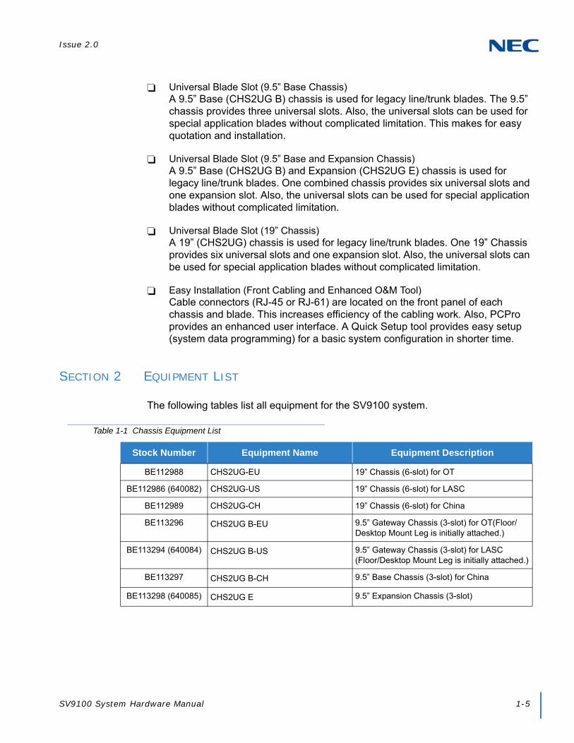
Issue 2.0
SV9100 System Hardware Manual 1-5
Universal Blade Slot (9.5” Base Chassis)A 9.5” Base (CHS2UG B) chassis is used for legacy line/trunk blades. The 9.5” chassis provides three universal slots. Also, the universal slots can be used for special application blades without complicated limitation. This makes for easy quotation and installation.
Universal Blade Slot (9.5” Base and Expansion Chassis)A 9.5” Base (CHS2UG B) and Expansion (CHS2UG E) chassis is used for legacy line/trunk blades. One combined chassis provides six universal slots and one expansion slot. Also, the universal slots can be used for special application blades without complicated limitation.
Universal Blade Slot (19” Chassis)A 19” (CHS2UG) chassis is used for legacy line/trunk blades. One 19” Chassis provides six universal slots and one expansion slot. Also, the universal slots can be used for special application blades without complicated limitation.
Easy Installation (Front Cabling and Enhanced O&M Tool)Cable connectors (RJ-45 or RJ-61) are located on the front panel of each chassis and blade. This increases efficiency of the cabling work. Also, PCPro provides an enhanced user interface. A Quick Setup tool provides easy setup (system data programming) for a basic system configuration in shorter time.
SECTION 2 EQUIPMENT LIST
The following tables list all equipment for the SV9100 system.
Table 1-1 Chassis Equipment List
Stock Number Equipment Name Equipment Description
BE112988 CHS2UG-EU 19” Chassis (6-slot) for OT
BE112986 (640082) CHS2UG-US 19” Chassis (6-slot) for LASC
BE112989 CHS2UG-CH 19” Chassis (6-slot) for China
BE113296 CHS2UG B-EU 9.5” Gateway Chassis (3-slot) for OT(Floor/Desktop Mount Leg is initially attached.)
BE113294 (640084) CHS2UG B-US 9.5” Gateway Chassis (3-slot) for LASC (Floor/Desktop Mount Leg is initially attached.)
BE113297 CHS2UG B-CH 9.5” Base Chassis (3-slot) for China
BE113298 (640085) CHS2UG E 9.5” Expansion Chassis (3-slot)

Issue 2.0
1-6 Introduction to SV9100
Table 1-2 Chassis Installation Equipment List
Stock Number Equipment Name Equipment Description
BE113300(640087) CHS2UG MOVABLE WALL MOUNT KIT
Movable Wall Mount Set for CHS2UG B and CHS2UG E chassis
BE106406(670019) CHS BASE UNIT Floor Mount Set for all chassis (CHS1UG and CHS2UG)
BE113121 CHS2UG BLANK SLOT COVER KIT Blank Slot Cover Set
BE106414(670501) CHS2U JOINT BRACKET KIT Upper Joint Bracket for 6-slot Chassis
BE106405(670508) CHS2U RACK MOUNT KIT Rack Mount for CHS2U Chassis
BE106407(670510) CHS1U/2U WALL MOUNT KIT Wall Mount Set for 2U Chassis
BE106910(670513) CHS2U Stand Kit (K) Stand Mount Kit for 2UG Chassis
BE106727(670522) CHS2U STAND KIT (EXT) Expansion Plate for Stand Mount Kit for 6-blade Chassis, 2 sets
BE113068(640101) CHS2UG FRONT COVER Front Cover for 19-inch 2U Chassis
BE113444(640523) CHS1UG BLANK SLOT COVER KIT(BUS)
Blank Bus Cover
BE113150(640103) CHS2UG B FRONT COVER Front Cover for 2UG-B Chassis
BE113151(640103) CHS2UG B FRONT COVER EXP Front Cover for 2UG-E Chassis
BE113299(640086) IP5D-RACK MOUNT BAR SET Rack Mount Set for CHS2UG B andCHS2UG E
BE107555(0910013) IP3WW-STD BRACKET SET Stand bracket set
BE107557(0910011) IP3WW-STD BRACKET (EXTEND) Stand bracket set (Extend)
BE106729(670507) CHS2U FAN BOX SET FAN Unit for 2U Chassis (for Maintenance)
Table 1-3 Battery Mount Equipment List
Stock Number Equipment Name Equipment Description
BE113148(640088) CHS2UG B SMALL BATT BOX Short-term battery box for 3-slot chassisBackup Time – 10 minutes
BE113149(640083) CHSG LARGE BATT BOX Long Term Battery Box for CHS1UG and CHS2UG ChassisCable between batteries – 9.06in/230mmFuse Unit to Batteries – 18.11ln/460mmCable from chassis to battery box – 81.1in/2060mm
BE106403(670509) CHS2UG BATT MTG KIT Battery Mount for CHS2UG ChassisBackup time – 10 minutes

Issue 2.0
SV9100 System Hardware Manual 1-7
Table 1-4 Blade Equipment List
Stock Number Equipment Name Abbreviations Equipment Description
BE113218(640078)
GCD-CP10 CPU Main Processor Blade for KTS
BE113288 SD-A1 OT 1G-APP-CF Main Software including VRS/InMail SD Card (1GB)
BE113289 SD-B1 OT 4G-APP-CF Main Software including VRS/InMail SD Card (4GB)
BE114723(640113)
SD-A1 UL 1G-APP-CF Main Software including VRS/InMail SD Card (1GB) for U-Law
BE114724(640114)
SD-B1 UL 4G-APP-CF Main Software including VRS/InMail SD Card (4GB) for U-Law
BE113290 SD-A1 CH 1G-APP-CF Main Software including VRS/InMail SD Card (1GB)
BE113291 SD-B1 CH 4G-APP-CF Main Software including VRS/InMail SD Card (4GB)
BE113016(640055)
GPZ-BS10 BUS0 Expansion Chassis Interface Unit, 3-jack
BE113017(640056)
GPZ-BS11 BUS1 Expansion Chassis Interface Unit, 1-jack
BE113018(640057)
GCD-8DLCA DLC 8-port Digital Station Interface
BE113019(640058)
GPZ-8DLCB DLCDB 8-port Digital Station Interface on GCD-8DLCA
BE113020(640059)
GCD-16DLCA DLC 16-port Digital Station Interface
BE113026 BE113031
GCD-4COTA GCD-4COTC
COT 4-port Loop/ground Start Trunks
BE113028 BE113032
GPZ-4COTE GPZ-4COTG
COTDB 4-port Loop/ground Start Trunks on GCD-4COTA/C (for GPZ-4COTE/G), GCD-LTA
BE113434(640096)
GCD-4LCF LC 4-port Single Line Telephone Interface for all Market (Except China).
BE113435(640097)
GCD-8LCF LC 8-port Single Line Telephone Interface for all Market (Except China).
BE113436(640098)
GPZ-4LCF LCDB 4-port Single Line Telephone Interface on GCD-4LCF and GCD-8LCF for all Market (Except China).
BE113437(640099)
GPZ-8LCF LCDB 8-port Single Line Telephone Interface on GCD-4LCF and GCD-8LCF for all Market (Except China).

Issue 2.0
1-8 Introduction to SV9100
BE114107 GCD-4LCG LC 4-port Single Line Telephone Interface for China.
BE114108 GCD-8LCG LC 8-port Single Line Telephone Interface for China.
BE114109 GPZ-4LCG LCDB 4-port Single Line Telephone Interface on GCD-4LCG and GCD-8LCG for China.
BE114110 GPZ-8LCG LCDB 8-port Single Line Telephone Interface on GCD-4LCG and GCD-8LCG for China.
BE113033(640066)
GCD-2BRIA BRT 2 Basic Rate Interface
BE113034(640067)
GPZ-2BRIA BRTDB 2 Basic Rate Interface on GCD-2BRIA, for SV9100 can also be mounted on the GCD-LTA blade
BE113037(640068)
GCD-PRTA PRT 1 Primary Rate Interface
BE113038(640069)
GCD-CCTA CCT Common Channel Interoffice Signaling Trunk Interface/Common Channel Handler
BE113040 GCD-4DIOPB DIOP 4 DID/OPX
BE113042 GCD-4ODTB ODT 4-port Tie Line Interface (E&M)
BE113170(640072)
GCD-LTA LTA 8 Digital Station/2SLT for GCD-CP10 only
BE113281(640073)
GPZ-IPLE VoIPDB VOIP on the CPU (Max.256ch)
BE113046(640074)
GCD-VM00 VM00 Voice Mail and Server for all Market (Except China).
640837 SV9193-UM-8G APP CF
CF Card for UM8000 (for LASC)
BE107807 AKS UM-2G OT CF Card for UM8000 (for Asia)
BE107808 AKS UM-8G OT CF Card for UM8000 (for Asia)
BE113045(640075)
GCD-ETIA GSWU In-Skin PoE Gigabit Switch Unit (8ch) for all Market (Except China).
BE113050(640076)
GCD-PVAA PMS IN-Skin Hotel PMS for all Market (Except China).
BE113292(640081)
GCD-RGA RGA In-Skin Router/Switching HUB(4ch)/ Conference Bridge for all Market.
BE113293(640195)
AKS-RGA-APP-GATEWAY-CF
AKS-RGA CF Compact Flash Card for Conference Bridge (Mount to GCD-RGA) (Except China).
BE114493 AKS-RGA-APP-GATEWAY-CF(CH)
AKS-RGA CF Compact Flash Card for Conference Bridge (Mount to GCD-RGA) for China
Table 1-4 Blade Equipment List (Continued)
Stock Number Equipment Name Abbreviations Equipment Description

Issue 2.0
SV9100 System Hardware Manual 1-9
Table 1-5 Cable Equipment List
Stock Number Equipment Name Equipment Description
BE106737(670530) CHS2U BATT CA INT CHS2UG Battery Cable for Internal Battery 2U ChassisCable A – 18.9in/480mmCable B – 3.15in/80mm
BE106738(670531) CHS2U BATT CA EXT-A Battery Cable for External Battery 6-slot Chassis
Table 1-6 Digital Multiline Terminal (DT300 Series) Equipment List
Stock Number Equipment Name Equipment Description
BE106971(680000) DTZ-2E-3 (BK) TEL Economy Digital 2-button Telephone for LASC (No-Display)
BE106854 DTL-2E-1P (BK) TEL Economy Digital 2-button Telephone for Asia (No-Display)
BE10972(680001) DTZ-6DE-3 (BK) TEL Economy Digital 6-button Display Telephone for LASC
BE106855 DTL-6DE-1P (BK) TEL Economy Digital 6-button Display Telephone for Asia
BE111355(680062) DTL-12E-1 (BK) TEL Economy Digital 12-button Display Telephone for LASC
BE106974(680002)BE106973(680003)
DTZ-12D-3 (BK) TELDTZ-12D-3 (WH) TEL
Value Digital 12-button Display Telephone for LASC
BE106856BE107323
DTL-12D-1P (BK) TELDTL-12D-1P (WH) TEL
Value Digital 12-button Display Telephone for Asia
BE106976(680004)BE106975(680005)
DTZ-24D-3 (BK) TELDTZ-24D-3 (WH) TEL
Value Digital 24-button Display Telephone for LASC
BE106857BE107324
DTL-24D-1P (BK) TELDTL-24D-1P (WH) TEL
Value Digital 24-button Display Telephone for Asia
BE106978(680006)BE106977(680007)
DTZ-32D-3 (BK) TELDTL-32D-1 (WH) TEL
Value Digital 32-button Display Telephone for LASC
BE106858 DTL-32D-1P (BK) TEL Value Digital 32-button Display Telephone for Asia
BE108946(680008) DTL-12BT-1 (BK) TEL Value Digital 12-button Telephone with Bluetooth Cordless Headset for LASC
BE106860 DTL-12BT-1P (BK) TEL Value Digital 12-button Telephone with Bluetooth Cordless Headset for Asia

Issue 2.0
1-10 Introduction to SV9100
BE106979(680009) DTL-12PA-1 (BK) TEL Value Digital 12-button Telephone with Power Failure Adapter for LASC
BE106861 DTL-12PA-1P (BK) TEL Value Digital 12-button Telephone with Power Failure Adapter for Asia
BE113809(680010)BE113808(680011)
DTL-8LD-1 (BK) TELDTL-8LD-1 (WH) TEL
Value Digital 8-button Telephone (DESI-less) for LASC
BE106859BE107325
DTL-8LD-1P (BK) TELDTL-8LD-1P (WH) TEL
Value Digital 8-button Telephone (DESI-less) for Asia
BE106985(680012)BE106984(680013)
DCL-60-1 (BK) CONSOLEDCL-60-1 (WH) CONSOLE
60-button Direct Station Selection (DSS) Console for LASC
BE106876BE107330
DCL-60-1P (BK) CONSOLEDCL-60-1P (WH) CONSOLE
60-button Direct Station Selection (DSS) Console for Asia
BE106987(680014)BE106986(680015)
8LK-L (BK) UNIT8LK-L (WH) UNIT
8-button Line Key Unit for LASC
BE106877BE107331
8LK-LP (BK) UNIT8LK-LP (WH) UNIT
8-button Line Key Unit for Asia
BE106884(680016) BE107663(680017)
8LKD (LD)-L (BK) UNIT8LKD (LD)-L (WH) UNIT
DESI-less 8-button Line Key Unit/LCD Unit for Digital Telephone
BE106886(680608) BE107665(680609)
LCD (BL)-L (BK) UNITLCD (BL)-L (WH) UNIT
LCD Unit (Backlight LCD) for Digital Telephone
Table 1-7 Digital Multiline Terminal (DT400 Series) Equipment List
Stock Number Equipment Name Equipment Description
BE11810(650000) DTZ-2E-3 (BK) TEL Economy Digital 2-button Telephone (No-Display) for LASC
BE113867 DTZ-2E-3P (BK) TEL Economy Digital 2-button Telephone (No-Display) for Asia
BE103811(650001) DTZ-6DE-3 (BK) TEL Economy Digital 6-button Display Telephone for LASC
BE113868 DTZ-6DE-3P (BK) TEL Economy Digital 6-button Display Telephone for Asia
BE113805(650002)BE113804(650003)
DTZ-12D-3 (BK) TELDTZ-12D-3 (WH) TEL
Value Digital 12-button Display Telephone for LASC
BE113862BE113861
DTZ-12D-3P (BK) TELDTZ-12D-3P (WH) TEL
Value Digital 12-button Display Telephone for Asia
BE113807(680004)BE113806(680005)
DTZ-24D-3 (BK) TELDTZ-24D-3 (WH) TEL
Value Digital 24-button Display Telephone for LASC
Table 1-6 Digital Multiline Terminal (DT300 Series) Equipment List (Continued)
Stock Number Equipment Name Equipment Description

Issue 2.0
SV9100 System Hardware Manual 1-11
BE113864BE113863
DTZ-24D-3P (BK) TELDTZ-24D-3P (WH) TEL
Value Digital 24-button Display Telephone for Asia
BE113809(680010)BE113808(680011)
DTZ-8LD-3 (BK) TELDTZ-8LD-3 (WH) TEL
Value Digital 8-button Telephone (DESI-less) for LASC
BE113866BE113865
DTZ-8LD-3P (BK) TELDTZ-8LD-3P (WH) TEL
Value Digital 8-button Telephone (DESI-less) for Asia
BE113813(680012)BE113812(680013)
DCZ-60-2 (BK) CONSOLEDCZ-60-2 (WH) CONSOLE
60-button Direct Station Selection (DSS) Console for LASC
BE113870BE113869
DCZ-60-2P (BK) CONSOLEDCZ-60-2P (WH) CONSOLE
60-button Direct Station Selection (DSS) Console for Asia
BE113815(680014)BE113814(680015)
8LK-Z (BK) UNIT8LK-Z (WH) UNIT
8-button Line Key Unit for LASC
BE113872BE113871
8LK-ZP (BK) UNIT8LK-ZP (WH) UNIT
8-button Line Key Unit for Asia
BE113837(660118)BE113836
12LK-Z (BK) UNIT12LK-Z (WH) UNIT
12-button Line Key Unit for 12DG/12CG only for Asia and LASC
Table 1-7 Digital Multiline Terminal (DT400 Series) Equipment List (Continued)
Stock Number Equipment Name Equipment Description
Table 1-8 IP Multiline Terminal (DT700 Series) Equipment List
Stock Number Equipment Name Equipment Description
BE106990(690000) ITL-2E-1 (BK) TEL Economy IP 2-button Telephone (No Display) for LASC
BE106862 ITL-2E-1P (BK) TEL Economy IP 2-button Telephone (No Display) for Asia
BE106991(690001) ITL-6DE-1 (BK) TEL Economy IP 6-button Display Telephone for LASC
BE106863 ITL-6DE-1P (BK) TEL Economy IP 6-button Display Telephone for Asia
BE111239(690071) ITL-8LDE-1 (BK) TEL Economy IP 8-button Display Telephone for LASC
BE111238 ITL-8LDE-1P (BK) TEL Economy IP 8-button Display Telephone for Asia
BE106993(690002)BE106992(690003)
ITL-12D-1 (BK) TELITL-12D-1 (WH) TEL
Value IP 12-button Display Telephone for LASC
BE106864BE107326
ITL-12D-1P (BK) TELITL-12D-1P (WH) TEL
Value IP 12-button Display Telephone for Asia
BE111490(690077) ITL-12CG-3 (BK) TEL Value IP 12-button Display Telephone (Color) for LASC

Issue 2.0
1-12 Introduction to SV9100
BE111489BE111488
ITL-12CG-3P (BK) TELITL-12CG-3P (WH) TEL
Value IP 12-button Display Telephone (Color) for Asia
BE111486(690078) ITL-12DG-3 (BK) TEL Value IP 12-button Display Telephone (Grayscale) for LASC
BE111485BE111484
ITL-12DG-3P (BK) TELITL-12DG-3P (WH) TEL
Value IP 12-button Display Telephone (Grayscale) for Asia
BE106995(690004)BE106994(690005)
ITL-24D-1 (BK) TELITL-24D-1 (WH) TEL
Value IP 24-button Display Telephone for LASC
BE106865BE107327
ITL-24D-1P (BK) TELITL-24D-1P (WH) TEL
Value IP 24-button Display Telephone for Asia
BE106997(690006)BE106996(690007)
ITL-32D-1 (BK) TELITL-32D-1 (WH) TEL
Value IP 32-button Display Telephone for LASC
BE106866 ITL-32D-1P (BK) TEL Value IP 32-button Display Telephone for Asia
BE106998(690009) ITL-12PA-1 (BK) TEL Value IP 12-button Telephone with Power Failure Adapter for LASC
BE106869 ITL-12PA-1P (BK) TEL Value IP 12-button Telephone with Power Failure Adapter for Asia
BE107000(690010)BE106999(690011)
ITL-8LD-1 (BK) TELITL-8LD-1 (WH) TEL
Value IP 8 Line Key Display TelephoneValue IP Telephone: DESI-less for LASC
BE109275(4424005) ITL-8LD-1A (BK) TEL Value IP 8 Line Key Display TelephoneValue IP Telephone: DESI-less for Australia
BE106867BE107328
ITL-8LD-1P (BK) TELITL-8LD-1P (WH) TEL
Value IP 8 Line Key Display TelephoneValue IP Telephone: DESI-less for Asia
BE106885(690013)BE107664(690014)
8LKI (LD)-L (BK) UNIT8LKI (LD)-L (WH) UNIT
DESI-less LK/LCD Unit for IP
BE109273(690019) ITL-320C-2 (BK) TEL Sophisticated Telephone (Class-B) for LASC
BE110714 ITL-320C-2P (BK) TEL Sophisticated Telephone (Class-B) for Asia
BE112078(690080) ITL-2CR-1 (BK) TEL Cradle Phone for LASC
BE112077 ITL-2CR-1P (BK) TEL Cradle Phone for Asia
Table 1-8 IP Multiline Terminal (DT700 Series) Equipment List (Continued)
Stock Number Equipment Name Equipment Description
Table 1-9 IP Multiline Terminal (DT800 SERIES) Equipment List
Stock Number Equipment Name Equipment Description
BE113795(690002)BE113794(690003)
ITZ-12D-3 (BK) TELITZ-12D-3 (WH) TEL
Value IP 12-button Display Telephone for LASC
BE113852BE113851
ITZ-12D-3P (BK) TELITZ-12D-3P (WH) TEL
Value IP 12-button Display Telephone for Asia

Issue 2.0
SV9100 System Hardware Manual 1-13
BE113803(660021) ITZ-12CG-3 (BK) TEL Value IP 12-button Display Telephone (Color) for LASC
BE113860BE113859
ITZ-12CG-3P (BK) TELITZ-12CG-3P (WH) TEL
Value IP 12-button Display Telephone (Color) for Asia
BE113802(660020) ITZ-12DG-3 (BK) TEL Value IP 12-button Display Telephone (Grayscale) for LASC
BE113858BE113857
ITZ-12DG-3P (BK) TELITZ-12DG-3P (WH) TEL
Value IP 12-button Display Telephone (Grayscale) for Asia
BE113797(660004)BE113796(660005)
ITZ-24D-1 (BK) TELITZ-24D-1 (WH) TEL
Value IP 24-button Display Telephone for LASC
BE113854BE113853
ITZ-24D-3P (BK) TELITZ-24D-3P (WH) TEL
Value IP 24-button Display Telephone for Asia
BE113799(690010)BE113798(690011)
ITZ-8LD-3 (BK) TELITZ-8LD-3 (WH) TEL
Value IP 8 Line Key Display TelephoneValue IP Telephone: DESI-less for LASC
BE113801(660018)BE113800(660019)
ITZ-8LDG-3 (BK) TELITZ-8LDG-3 (WH) TEL
Value IP 8 Line Key Display TelephoneValue IP Telephone: DESI-less for LASC
BE113856BE113855
ITZ-8LDG-3P (BK) TELITZ-8LDG-3P (WH) TEL
Value IP 8 Line Key Display TelephoneValue IP Telephone: DESI-less for Asia
Table 1-9 IP Multiline Terminal (DT800 SERIES) Equipment List (Continued)
Stock Number Equipment Name Equipment Description
Table 1-10 SV9100 Optional Equipment List
Stock Number Equipment Name Equipment Description
BE112222(670553) IP3NE-IPCDH IP Video Doorphone
BE112235(670554) IP3WW-CDH BRACKET SET Bracket set for IP Video Doorphone
BE112236(670555) IP3WW-CDH WALL COVER SET Wall Cover set for IP Video Doorphone
BE106982(680600) APR-L UNIT Analog Port Ringer (DT300 or DT400 only)
BE106983(680601) ADA-L UNIT Ancillary Device Adapter
BE108900(680602) BHA-L UNIT Bluetooth® Hub Adapter
BE113817(660022) BCA-Z UNIT Bluetooth Connection Adapter for LASC
BE113873 BCA-ZP UNIT Bluetooth Connection Adapter for Asia
BE107003(680603)BE107002(680604)
PSA-L (BK) UNITPSA-L (WH) UNIT
Power Save Adapter
BE108898(680605) BCH-L (BK) UNIT Bluetooth Cordless Handset
BE106883(680606)BE107662(680607)
12LK-L (BK) KIT12LK-L (WH) KIT
12-button Line Key Kit

Issue 2.0
1-14 Introduction to SV9100
BE106887(680610) WM-L UNIT Wall Mount Unit
BE107666(680754) DSS WM-L UNIT Wall Mount Unit for DCL-60-1
BE108179(680650) DESI ITL/DTL-2E (25 PKG) DESI Sheet for Economy 2-button Telephone (2 Part Sheet, 25 Package)
BE108780(680651) DESI ITL/DTL-6DE (25 PKG) DESI Sheet for Economy 6-button Display Telephone (2 Part Sheet, 25 Package)
BE108181(680652) DESI ITL/DTL-12D (25 PKG) DESI Sheet for Value 12-button Display Telephone (2 Part Sheet, 25 Package)
BE108183(680653) DESI ITL/DTL-8LK (25 PKG) DESI Sheet for 8-button Line Key (1 Part Sheet, 25 Package)
BE108185(680654) DESI DCL-60 DSS(25 PKG) DESI Sheet for 60DSS (1 Part Sheet, 25 Package)
BE108186(680655) DESI ITL/DTL-SIDE (25 PKG) DESI Sheet for Clear Side Panel (Left and Right Part Sheet, 25 Package)
BE108187(680656) DESI ITL/DTL-SIDE-LCDV (25 PKG) DESI Sheet for Value Telephone LCD (Left and Right Part Sheet, 25 Package)
BE108188(680657) DESI ITL/DTL-SIDE-LCDS (25 PKG) DESI Sheet for Sophisticated Telephone LCD (Left and Right Part Sheet, 25 Package)
BE108189(680658) DESI ITL/DTL DIR CARD Directory Card
BE108182(680659) DESI ITL/DTL-24D (25 PKG) DESI Sheet for Value 24-button Display Telephone (2 Part Sheet, 25 Package)
BE107667(680700) Panel (Red-Base)-L UNIT Color Side Panel for Base (Red)
BE107668(680701) Panel (Red-VLCD)-L UNIT Color Side Panel for Value Telephone LCD (Red)
BE107669(680702) Panel (Red-SLCD)-L UNIT Color Side Panel for Sophisticated Telephone LCD (Red)
BE107670(680703) Panel (Blue-Base)-L UNIT Color Side Panel for Base (Blue)
BE107671(680704) Panel (Blue-VLCD)-L UNIT Color Side Panel for Value Telephone LCD (Blue)
BE107672(680705) Panel (Blue-SLCD)-L UNIT Color Side Panel for Sophisticated Telephone LCD (Blue)
BE107248(680706) Panel (Silver-Base)-L UNIT Color Side Panel for Base (Silver)
BE107249(680707) Panel (Silver-VLCD)-L UNIT Color Side Panel for Value Telephone LCD (Silver)
BE107250(680708) Panel (Silver-SLCD)-L UNIT Color Side Panel for Sophisticated Telephone LCD (Silver)
BE107673(680709) Panel (Wood-Base)-L UNIT Color Side Panel for Base (Wood)
BE107674(680710) Panel (Wood-VLCD)-L UNIT Color Side Panel for Value Telephone LCD (Wood)
Table 1-10 SV9100 Optional Equipment List (Continued)
Stock Number Equipment Name Equipment Description

Issue 2.0
SV9100 System Hardware Manual 1-15
BE107675(680711) Panel (Wood-SLCD)-L UNIT Color Side Panel for Sophisticated Telephone LCD (Wood)
BE107676(680712) Panel (Logo-Base)-L UNIT Color Side Panel for Base (Wood with Logo)
BE107677(680713) Panel (Clear-Base)-L UNIT Color Side Panel for Base (Clear)
BE109318(680714) LKPANEL(2BTN)-L (BK) UNIT Spare Plastic Cover Kit (2-button) (Black)
BE109320(680715) LKPANEL(6BTN)-L (BK) UNIT Spare Plastic Cover Kit (6-button) (Black)
BE109316(680716)BE109321(680717)
LKPANEL(12BTN)-L (BK) UNITLKPANEL(12BTN)-L (WH) UNIT
Spare Plastic Cover Kit (12-button)
BE109317(680718)BE109322(680719)
LKPANEL(24BTN)-L (BK) UNITLKPANEL(24BTN)-L (WH) UNIT
Spare Plastic Cover Kit (24-button)
BE109324(680720)BE109325(680721)
LKPANEL(8BTN)-L (BK) UNITLKPANEL(8BTN)-L (WH) UNIT
Spare Plastic Cover Kit (8-button)
BE109319(680722)BE109323(680723)
LKPANEL(60BTN)-L (BK) UNITLKPANEL(60BTN)-L (WH) UNIT
Spare Plastic Cover Kit (60-button)
BE107680(680738) VAL DIRECTORY CARD UNIT(L) Directory Card Holder for Value Telephone
BE107681(680739) ECO DIRECTORY CARD UNIT(L) Directory Card Holder for Economy Telephone
BE107678(680741) Panel (Clear-VLCD)-L UNIT Color Side Panel for Value Telephone LCD (Clear)
BE107679(680742) Panel (Clear-SLCD)-L UNIT Color Side Panel for Sophisticated Telephone LCD (Clear)
BE109309(680745)BE109310(680746)
KeyKitPanel (Value) (BK) UnitKeyKitPanel (Value) (WH) Unit
Spare Plastic Cover Key Kit for Value Telephone
BE109299(680747)BE109300(680748)
KeyKitPanel (Retro) (BK) UnitKeyKitPanel (Retro) (WH) Unit
Spare Plastic Cover Key Kit for Retro Telephone
BE109301(680749) KeyKitPanel (Sophi) (BK) Unit Spare Plastic Cover Key Kit for Sophisticated Telephone
BE109306(680756) KeyKitPanel(V)-L (M-Blue) Unit Color face panel for Value (Metallic Blue)1 set consists 10 of panels
BE109303(680757) KeyKitPanel(V)-L (GUNMETA) Unit Color face panel for Value (GunMetallic)1 set consists 10 of panels
BE109305(680758) KeyKitPanel(V)-L (L-Green-M) Unit Color face panel for Value (Lime Green Metallic) 1 set consists 10 of panels
BE109308(680759) KeyKitPanel(V)-L (Orange-M) Unit Color face panel for Value (Orange Metallic)1 set consists 10 of panels
BE109302(680760) KeyKitPanel(V)-L (D-Brown-M) Unit Color face panel for Value (Dark Brown Metallic) 1 set consists 10 of panels
BE108421(680761) LKPANEL(12BTN)-L(M-Blue) UNIT
Color LK panel (12button) for Value(Metallic Blue) 1 set consists 10 of panels
Table 1-10 SV9100 Optional Equipment List (Continued)
Stock Number Equipment Name Equipment Description
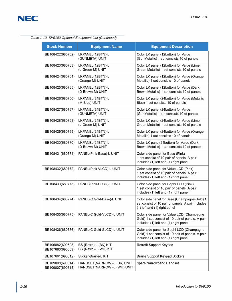
Issue 2.0
1-16 Introduction to SV9100
BE108422(680762) LKPANEL(12BTN)-L(GUNMETA) UNIT
Color LK panel (12button) for Value (GunMetallic) 1 set consists 10 of panels
BE108423(680763) LKPANEL(12BTN)-L(L-Green-M) UNIT
Color LK panel (12button) for Value (Lime Green Metallic) 1 set consists 10 of panels
BE108424(680764) LKPANEL(12BTN)-L(Orange-M) UNIT
Color LK panel (12button) for Value (Orange Metallic) 1 set consists 10 of panels
BE108425(680765) LKPANEL(12BTN)-L(D-Brown-M) UNIT
Color LK panel (12button) for Value (Dark Brown Metallic) 1 set consists 10 of panels
BE108426(680766) LKPANEL(24BTN)-L(M-Blue) UNIT
Color LK panel (24button) for Value (Metallic Blue) 1 set consists 10 of panels
BE108427(680767) LKPANEL(24BTN)-L(GUNMETA) UNIT
Color LK panel (24button) for Value (GunMetallic) 1 set consists 10 of panels
BE108428(680768) LKPANEL(24BTN)-L(L-Green-M) UNIT
Color LK panel (24button) for Value (Lime Green Metallic) 1 set consists 10 of panels
BE108429(680769) LKPANEL(24BTN)-L(Orange-M) UNIT
Color LK panel (24button) for Value (Orange Metallic) 1 set consists 10 of panels
BE108430(680770) LKPANEL(24BTN)-L(D-Brown-M) UNIT
Color LK panel(24button) for Value (Dark Brown Metallic) 1 set consists 10 of panels
BE108431(680771) PANEL(Pink-Base)-L UNIT Color side panel for Base (Pink)1 set consist of 10 pair of panels. A pair includes (1) left and (1) right panel
BE108432(680772) PANEL(Pink-VLCD)-L UNIT Color side panel for Value LCD (Pink)1 set consist of 10 pair of panels. A pair includes (1) left and (1) right panel
BE108433(680773) PANEL(Pink-SLCD)-L UNIT Color side panel for Sophi LCD (Pink)1 set consist of 10 pair of panels. A pair includes (1) left and (1) right panel
BE108434(680774) PANEL(C Gold-Base)-L UNIT Color side panel for Base (Champagne Gold) 1 set consist of 10 pair of panels. A pair includes (1) left and (1) right panel
BE108435(680775) PANEL(C Gold-VLCD)-L UNIT Color side panel for Value LCD (Champagne Gold) 1 set consist of 10 pair of panels. A pair includes (1) left and (1) right panel
BE108436(680776) PANEL(C Gold-SLCD)-L UNIT Color side panel for Sophi LCD (Champagne Gold) 1 set consist of 10 pair of panels. A pair includes (1) left and (1) right panel
BE106882(690608)BE107660(690609)
BS (Retro)-L (BK) KITBS (Retro)-L (WH) KIT
Retrofit Support Keypad
BE107661(690612) Sticker-Braille-L KIT Braille Support Keypad Stickers
BE109008(690614)BE109007(690615)
HANDSET(NARROW)-L (BK) UNITHANDSET(NARROW)-L (WH) UNIT
Spare Narrowband Handset
Table 1-10 SV9100 Optional Equipment List (Continued)
Stock Number Equipment Name Equipment Description

Issue 2.0
SV9100 System Hardware Manual 1-17
BE109012(690616)BE109011(690617)
HANDSET(WIDE)-L (BK) UNITHANDSET(WIDE)-L (WH) UNIT
Spare Wideband Handset
BE109004(690618)BE109003(690619)
HandsetCord(12FT)-L (BK) SETHandsetCord(12FT)-L (WH) SET
Spare Handset Cord 12 Feet
BE109315(690627) LineCord-L (BK) SET Spare Line Cord (BK)
BE108048 GBA-LP Gigabit Adapter
BE108059 AC-L AC Adapter for GBA-L UNIT
BE109378(690633) BS(S-HOTEL)-L (BK) UNIT Standard Hotel function keypad for Sophi (BK) with Blank D/F panel
BE111492(690638) CG Directory Card Holder CG Directory Card Unit
Table 1-10 SV9100 Optional Equipment List (Continued)
Stock Number Equipment Name Equipment Description

Issue 2.0
1-18 Introduction to SV9100
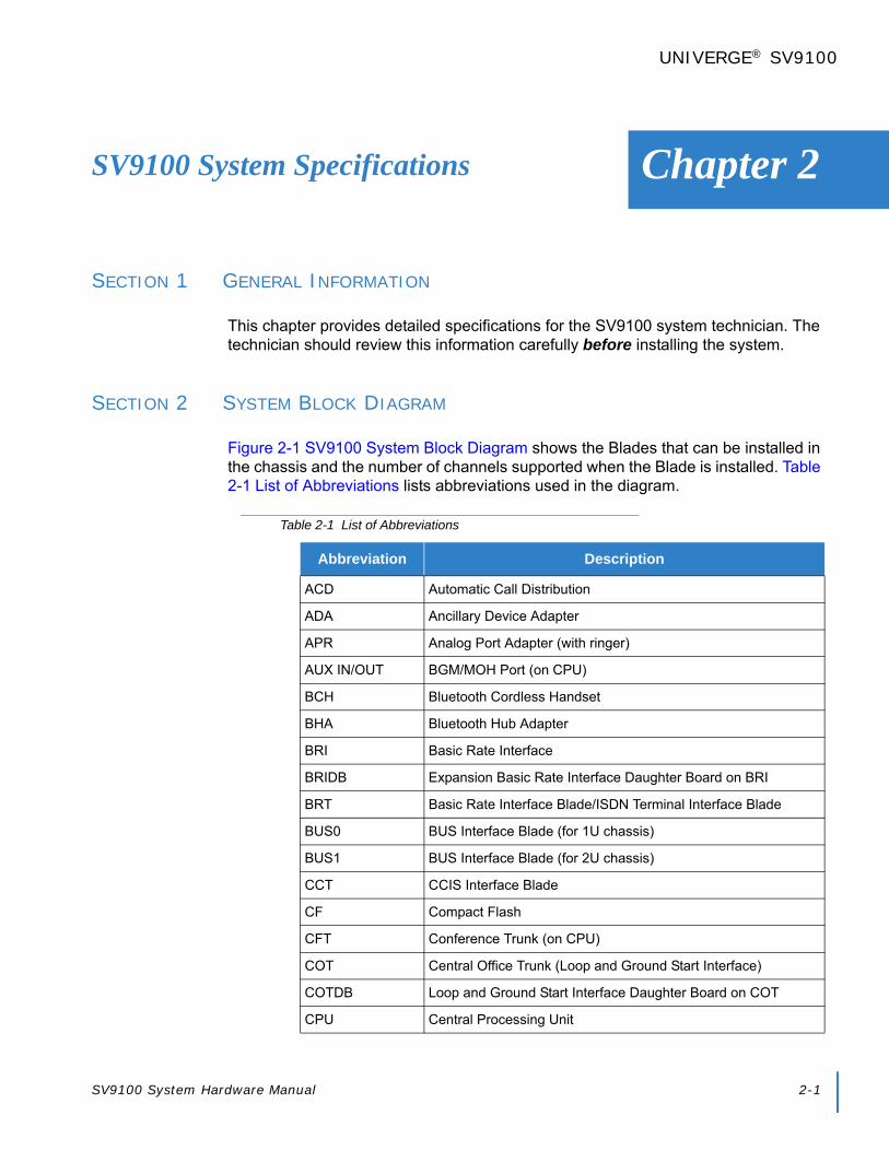
SV9100 System Hardware Manual 2-1
Chapter 2
UNIVERGE® SV9100
SV9100 System Specifications
SECTION 1 GENERAL INFORMATION
This chapter provides detailed specifications for the SV9100 system technician. The technician should review this information carefully before installing the system.
SECTION 2 SYSTEM BLOCK DIAGRAM
Figure 2-1 SV9100 System Block Diagram shows the Blades that can be installed in the chassis and the number of channels supported when the Blade is installed. Table 2-1 List of Abbreviations lists abbreviations used in the diagram.
Table 2-1 List of Abbreviations
Abbreviation Description
ACD Automatic Call Distribution
ADA Ancillary Device Adapter
APR Analog Port Adapter (with ringer)
AUX IN/OUT BGM/MOH Port (on CPU)
BCH Bluetooth Cordless Handset
BHA Bluetooth Hub Adapter
BRI Basic Rate Interface
BRIDB Expansion Basic Rate Interface Daughter Board on BRI
BRT Basic Rate Interface Blade/ISDN Terminal Interface Blade
BUS0 BUS Interface Blade (for 1U chassis)
BUS1 BUS Interface Blade (for 2U chassis)
CCT CCIS Interface Blade
CF Compact Flash
CFT Conference Trunk (on CPU)
COT Central Office Trunk (Loop and Ground Start Interface)
COTDB Loop and Ground Start Interface Daughter Board on COT
CPU Central Processing Unit

Issue 2.0
2-2 SV9100 System Specifications
DID Direct Inward Dialing
DIOP DID/OPX Blade
DLC Digital Multiline Terminal Interface Blade
DLCB Expansion Digital Multiline Terminal Interface Blade on DLC
DRS Device Registration Server (on CPU)
DSS Direct Station Selection Console
DTI Digital Trunk Interface
DTG Digital Tone Generator (on CPU)
ETHERNET Ethernet Port (on CPU)
FT1 Fractional T1
GBA GigaBit Adapter
GSWU Power over Ethernet Gigabit Switch
IDF Intermediate Distribution Frame
IPT IP Trunk (P2P CCIS) (on CPU)
ISDN Integrated Service Digital Network
LAN Local Area Network
LC Single Line Telephone Interface Blade
LCDB Single Line Telephone Interface Daughter Board on LC
MDF Main Distribution Frame
MEM Main Memory (on CPU)
MIS Management Information System
MOH Music On Hold
OAI Open Application Interface (on CPU)
ODT Tie Line Interface Blade (2W/4W E&M)
OPX Off-Premise Extension
PBR PB Receiver (on CPU)
PBSND PB Sender (on CPU)
PCPro PC Programming
PFT Power Failure Transfer
PLO Phase Locked Oscillator (on CPU)
PMS Property Management System
PRI Primary Rate Interface
Table 2-1 List of Abbreviations
Abbreviation Description

Issue 2.0
SV9100 System Hardware Manual 2-3
PRT Primary Rate Interface Blade
PS Personal Station
PSA PSTN Adapter (analog)
PVA Packet Voice Application
RTB Router Blade
SERIAL Serial Port (on CPU)
SLT Single Line Telephone
SMDR Station Message Detail Recording
TDSW Time Division Switch (on CPU)
USB Universal Serial Bus (on CPU)
GCD-VM00 UMS Blade Server Blade (SV9100 only)
VMS Voice Mail System
VoIP Voice over Internet Protocol
VoIPDB VoIP Daughter Board (on CPU)
VRS Voice Response System
WAN Wide Area Network
WebPro Web-Based PC Programming
Table 2-1 List of Abbreviations
Abbreviation Description

Issue 2.0
2-4 SV9100 System Specifications
Figure 2-1 SV9100 System Block Diagram

Issue 2.0
SV9100 System Hardware Manual 2-5
SECTION 3 MAXIMUM SYSTEM CAPACITIES
3.1 Trunk/Port/Channel Capacities
The CHS2UG is a compact 19” chassis that has six universal slots, one expansion slot and one MPS7101 (power supply unit). When the GCD-CP10 is installed in the first CHS2UG, it is called the Controlling Chassis. Additional chassis, called Expansion Chassis, can be installed to increase the capacity of the system to meet the customer’s business needs.
As Figure 2-2 19” Controlling and Expansion Chassis and Table 2-2 SV9100 9.5” Gateway and 19” Maximum System Capacities – Trunks/Ports/Channels illustrate, the system can be expanded from 64 ports to 896 ports by vertically stacking a maximum of three additional chassis onto the controlling chassis. This provides a maximum of 24 slots and 368 digital terminals. To obtain the maximum port capacity of 896 ports, two systems can be linked together via an IP connection.
The maximum slot and channel capacities are listed in Table 2-2 SV9100 9.5” Gateway and 19” Maximum System Capacities – Trunks/Ports/Channels.
Table 2-2 SV9100 9.5” Gateway and 19” Maximum System Capacities – Trunks/Ports/Channels
Number of:
9.5” Chassis
19” Chassis
System Maximumx 1
(CPU + 2 Slots)
x 1(6 Slots)
x 2(12 Slots)
x 3(18 Slots)
X4(24 Slots)
Number of Timeslots 1 55 111 222 333 444 444
DT400/DT300 TDM (-48V) 32 80 176 272 368
Total 896
SLT (-28V) 32 80 176 272 368
SLT (-48V) 8 20 44 68 92
DT800/DT700 IP 896
Desktop Applications(Desktop Client, Desktop Client with Shared Services and SoftPhones)
256 Total 256
SIP/WLAN 896 Total 896
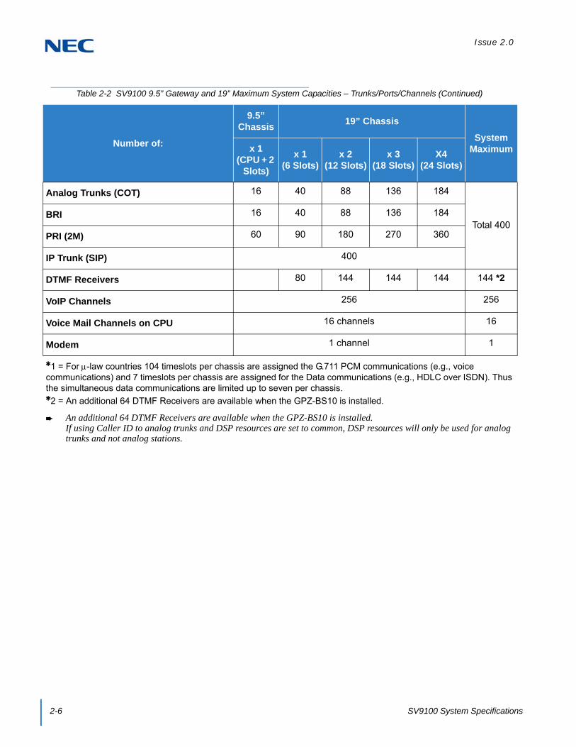
Issue 2.0
2-6 SV9100 System Specifications
Analog Trunks (COT) 16 40 88 136 184
Total 400BRI 16 40 88 136 184
PRI (2M) 60 90 180 270 360
IP Trunk (SIP) 400
DTMF Receivers 80 144 144 144 144 *2
VoIP Channels 256 256
Voice Mail Channels on CPU 16 channels 16
Modem 1 channel 1
1 = For-law countries 104 timeslots per chassis are assigned the G.711 PCM communications (e.g., voice communications) and 7 timeslots per chassis are assigned for the Data communications (e.g., HDLC over ISDN). Thus the simultaneous data communications are limited up to seven per chassis.2 = An additional 64 DTMF Receivers are available when the GPZ-BS10 is installed.
An additional 64 DTMF Receivers are available when the GPZ-BS10 is installed.If using Caller ID to analog trunks and DSP resources are set to common, DSP resources will only be used for analog trunks and not analog stations.
Table 2-2 SV9100 9.5” Gateway and 19” Maximum System Capacities – Trunks/Ports/Channels (Continued)
Number of:
9.5” Chassis
19” Chassis
System Maximumx 1
(CPU + 2 Slots)
x 1(6 Slots)
x 2(12 Slots)
x 3(18 Slots)
X4(24 Slots)

Issue 2.0
SV9100 System Hardware Manual 2-7
Figure 2-2 19” Controlling and Expansion Chassis
19” - 6 Slots
19” x 3 - 18 Slots
IP Connection
19” x 4 - 24 Slots
9.5” - 3 Slots
Issue 2.0
2-8 SV9100 System Specifications
There are two 9.5” chassis, the Base and Expansion. The base unit has three universal slots, one expansion slot and one MPS7101 (power supply unit). The expansion unit has three universal slots, no expansion slot, and no power supply unit. When the GCD-CP10 is installed in the first slot of the base chassis, it is called the Controlling Chassis. Additional chassis, called Expansion Chassis, can be installed to increase the capacity of the system to meet the customer’s business needs.
The system can be expanded from 64 ports to 896 ports by vertically stacking a maximum of three additional chassis onto the controlling chassis. This provides a maximum of 24 slots and 368 digital terminals. To obtain the maximum port capacity of 896 ports, three systems can be linked together via an IP connection.
Up to four combined CHS2UG B/CHS2UG E (3-Slot Base/3-Slot Expansion) or CHS2UG (6-Slot) chassis can be connected locally to reach the system’s maximum port capacity.
EXAMPLE:
0 CHS2UG (19” Chassis) & 4 CHS2UG B/CHS2UG E (9.5” BaseChassis/9.5” Expansion Chassis)
1 CHS2UG (19” Chassis) & 3 CHS2UG B/CHS2UG E (9.5” BaseChassis/9.5” Expansion Chassis)
2 CHS2UG (19” Chassis) & 2 CHS2UG B/CHS2UG E (9.5” BaseChassis/9.5” Expansion Chassis)
3 CHS2UG (19” Chassis) & 1 CHS2UG B/CHS2UG E (9.5” BaseChassis/9.5” Expansion Chassis)
4 CHS2UG (19” Chassis) & 0 CHS2UG B/CHS2UG E (9.5” BaseChassis/9.5” Expansion Chassis)

Issue 2.0
SV9100 System Hardware Manual 2-9
The maximum slot and channel capacities are listed in Table 2-3 SV9100 9.5” (Base and Expansion) Maximum System Capacities – Trunks/Ports/Channels.
Table 2-3 SV9100 9.5” (Base and Expansion) Maximum System Capacities – Trunks/Ports/Channels
Number of:
9.5” Base
9.5” Base + Expansion
System Maximumx 1
(CPU + 2 Slots)
x 1(6 Slots)
x 2(12 Slots)
x 3(18 Slots)
X4(24 Slots)
Number of Timeslots 1 55 111 222 333 444 444
DT400/DT300 TDM (-48V) 32 80 176 272 368
Total 896
SLT (-28V) 32 80 176 272 368
SLT (-48V) 8 20 44 68 92
DT800/DT700 IP 896
Desktop Applications(Desktop Client, Desktop Client with Shared Services and SoftPhones)
256 Total 256
SIP/WLAN 896 Total 896
Analog Trunks (COT) 16 40 88 136 184
Total 400BRI 16 40 88 136 184
PRI (2M) 60 90 180 270 360
IP Trunk (SIP) 400
DTMF Receivers 80 144 144 144 144 *2
VoIP Channels 256 256
Voice Mail Channels on CPU 16 channels 16
Modem 1 channel 1
1 = For-law countries 104 timeslots per chassis are assigned the G.711 PCM communications (e.g., voice communications) and 7 timeslots per chassis are assigned for the Data communications (e.g., HDLC over ISDN). Thus the simultaneous data communications are limited up to seven per chassis.2 = An additional 64 DTMF Receivers are available when the GPZ-BS10 is installed.
An additional 64 DTMF Receivers are available when the GPZ-BS10 is installed.If using Caller ID to analog trunks and DSP resources are set to common, DSP resources will only be used for analog trunks and not analog stations.

Issue 2.0
2-10 SV9100 System Specifications
3.2 System Chassis Capacities
Table 2-4 9.5” Gateway and 19” Maximum System Capacities – Chassis shows the maximum number of chassis and related equipment that can be installed in a system.
Table 2-4 9.5” Gateway and 19” Maximum System Capacities – Chassis
Hardware9.5”
Chassis
19” Chassis with CPU
19” Chassis without
CPU
19” Chassis
x4Networked
Chassis (NetLink)
Comments
Number of Slot(s) for Interface Package
3 Slots 5 Slots 6 Slots 23 Slots
Chassis:
CHS2UG GW(9.5” Chassis)
1 – – – – Gateway chassis
CHS2UG(19” Chassis)
– 1 1 4 50 x (1+3) Virtual slot in NetLink is limited to
maximum of 240
Expansion:
GPZ-BS103-jack Expansion Board for Controlling Chassis
0 1 0 1 –
GPZ-BS111-jack Expansion Board for Expansion Chassis
0 0 1 3 –
Battery:
CHSG LARGE BATT BOX(External Battery Box)
1 1 1 4 50 x (1+3) –
CHS2UG B SMALL BATT BOX(Small Battery Box)
1 – – – – –
Fan Box:
CHS2U FAN BOX SET 0 1 1 4 – 1 is factory installed with each
chassis
Power Supply:
MPS7101 1 1 1 4 – 1 is factory installed with each
chassis
Dependent on size of system.

Issue 2.0
SV9100 System Hardware Manual 2-11
Table 2-5 9.5” Base and Expansion Maximum System Capacities – Chassis shows the maximum number of chassis and related equipment that can be installed in a 9.5” Base and Expansion system.
Table 2-5 9.5” Base and Expansion Maximum System Capacities – Chassis
Hardware 9.5” Base
9.5” Base +
Expansion with CPU
9.5” Base +
Expansion without
CPU
9.5” Base +
Expansionx4
Networked Chassis (NetLink)
Comments
Number of Slot(s) for Interface Package
3 Slots 5 Slots 6 Slots 23 Slots
Chassis:
CHS2UG B (9.5” Base Chassis)
1 1 1 4 50 x (1+3) Virtual slot in NetLink is limited to maximum of
240CHS2UG E(9.5” Expansion Chassis)
– 1 1 4 50 x (1+3)
Expansion:
GPZ-BS103-port Expansion Board for Controlling Chassis
1 1 1 1 – –
GPZ-BS111-port Expansion Board for Expansion Chassis
0 1 1 3 – –
Battery:
CHSG LARGE BATT BOX(External Battery Box)
1 1 1 4 50 x (1+3) –
CHS2UG B SMALL BATT BOX(Small Battery Box)
1 1 1 4 50 x (1+3) –
Power Supply:
MPS7101 1 1 1 4 – 1 is factory installed with each
chassis

Issue 2.0
2-12 SV9100 System Specifications
3.3 Blade Capacities
This is determined by the maximum blade configuration allowed. When installing single line sets, DISA, or tie lines, CPU circuits must be allocated for DTMF receivers. To install single line sets with CO/PBX line access, or when installing immediate-start tie lines, CPU circuits must be allocated for dial tone detection.
Table 2-6 SV9100 Maximum 9.5” Gateway and 19” System Capacities – Blades
Hardware9.5”
Chassis
19” Chassis with CPU
19” Chassis without
CPU
19” Chassis
x4Networked
Chassis (NetLink)
Comments
Number of Slot(s) for Interface Package
3 Slots 5 Slots 6 Slots 23 Slots
Common Control Blades:
GCD-CP10 1 1 0 1 50 –
GPZ-IPLE(VoIP Daughter Board)
1 1 0 1 50 This unit provides 256 VOIP Gateway
channels
Station Blades:
GCD-4DIOPB(4 DID/OPX)
2 5 6 23 128 When installed as an OPX blade
GCD-8DLCA(8 Digital Station Interface)
2 5 6 23 112 –
GCD-16DLCA(16 Digital Station Interface)
2 5 6 23 56 –
GPZ-8DLCB(8 Digital Station Interface Daughter Board)
2 5 6 23 56 –
GCD-4LCF(4 Single Line Telephone Interface)
2 5 6 23 224
GCD-8LCF(8 Single Line Telephone Interface)
2 5 6 23 112
GPZ-4LCF(4 Single Line Telephone Interface Daughter Board)
2 5 6 23 74
GPZ-8LCF(8 Single Line Telephone Interface Daughter Board)
2 5 6 23 56
GCD-LTA
(8 Digital/2 Single Line)
2 2 2 8 23 An optional GPZ-4COT( ) or
GPZ-2BRIA can be installed

Issue 2.0
SV9100 System Hardware Manual 2-13
Trunk Blades:
GCD-2BRIA(2 Basic Rate Interface)
2 5 6 23 T interface = 100S interface = 224
–
GPZ-2BRIA(2 Basic Rate Interface Daughter Board)
2 5 6 23 T point = 50S point = 112
–
GCD-4COT( )(4 Loop/Ground Start Trunk)
2 5 6 23 100 –
GPZ-4COT( )(4 Loop/Ground Start Trunk Daughter Board)
2 5 6 23 50 –
GCD-4DIOPB(4 DID/OPX)
2 5 6 23 DID = 100OPX = 224
When installed as a DID blade
GCD-4ODTB(4 E&M)
2 5 6 23 100 –
GCD-PRTA(1 Primary Rate Interface)
2 3 3 12 13 Blade is used for Primary Rate
Interface or T-1 Interface
Optional Blades:
GCD-PVAA(Interactive Voice Response,PVA PMS)
1 1 1 1 1
GCD-ETIA(Switching Hub with Power over Ethernet)
2 3 3 12 64 –
GCD-VM00(Voice Mail and Server)
1 1 0 1 1 Maximum of One per system
GCD-RGA(Application Gateway – Router and Conference)
1 1 1 1 1 Maximum of One per system
Table 2-6 SV9100 Maximum 9.5” Gateway and 19” System Capacities – Blades (Continued)
Hardware9.5”
Chassis
19” Chassis with CPU
19” Chassis without
CPU
19” Chassis
x4Networked
Chassis (NetLink)
Comments
Number of Slot(s) for Interface Package
3 Slots 5 Slots 6 Slots 23 Slots

Issue 2.0
2-14 SV9100 System Specifications
Table 2-7 SV9100 Maximum 9.5” Base and Expansion System Capacities – Blades
Hardware9.5” Base
9.5” Base +
Expansion with CPU
9.5” Base +
Expansion without
CPU
9.5” Base +
Expansion with CPU
x4
Networked Chassis (NetLink)
Comments
Number of Slot(s) for Interface Package
3 Slots 5 Slots 6 Slots 23 Slots
Common Control Blades:
GCD-CP10 1 1 0 1 50 –
GPZ-IPLE(VoIP Daughter Board)
1 1 0 1 50 This unit provides 256 VOIP Gateway
channels
Station Blades:
GCD-4DIOPB(4 DID/OPX)
2 5 6 23 128 When installed as an OPX blade
GCD-8DLCA(8 Digital Station Interface)
2 5 6 23 112 –
GCD-16DLCA(16 Digital Station Interface)
2 5 6 23 56 –
GPZ-8DLCB(8 Digital Station Interface Daughter Board)
2 5 6 23 56 –
GCD-4LCF(4 Single Line Telephone Interface)
2 5 6 23 224
GCD-8LCF(8 Single Line Telephone Interface)
2 5 6 23 112
GPZ-4LCF(4 Single Line Telephone Interface Daughter Board)
2 5 6 23 74
GPZ-8LCF(8 Single Line Telephone Interface Daughter Board)
2 5 6 23 56
GCD-LTA
(8 Digital/2 Single Line)2 2 2 8 23 An optional GPZ-
4COT( ) or GPZ-2BRIA can be
installed

Issue 2.0
SV9100 System Hardware Manual 2-15
Trunk Blades:
GCD-2BRIA(2 Basic Rate Interface)
2 5 6 23 T interface = 100S interface = 224
–
GPZ-2BRIA(2 Basic Rate Interface Daughter Board)
2 5 6 23 T point = 50S point = 112
–
GCD-4COT( )(4 Loop/Ground Start Trunk)
2 5 6 23 100 –
GPZ-4COT( )(4 Loop/Ground Start Trunk Daughter Board)
2 5 6 23 50 –
GCD-4DIOPB(4 DID/OPX)
2 5 6 23 DID = 100OPX = 224
When installed as a DID blade
GCD-4ODTB(4 E&M)
2 5 6 23 100 –
GCD-PRTA(1 Primary Rate Interface)
2 3 3 12 13 Blade is used for Primary Rate
Interface or T-1 Interface
Optional Blades:
GCD-PVAA(Interactive Voice Response,PVA PMS)
1 1 1 1 1
GCD-ETIA(Switching Hub with Power over Ethernet)
2 3 3 12 64 –
GCD-VM00(Voice Mail and Server)
1 1 0 1 1 Maximum of One per system
GCD-RGA(Application Gateway – Router and Conference)
1 1 1 1 1 Maximum of One per system
Table 2-7 SV9100 Maximum 9.5” Base and Expansion System Capacities – Blades (Continued)
Hardware9.5” Base
9.5” Base +
Expansion with CPU
9.5” Base +
Expansion without
CPU
9.5” Base +
Expansion with CPU
x4
Networked Chassis (NetLink)
Comments
Number of Slot(s) for Interface Package
3 Slots 5 Slots 6 Slots 23 Slots
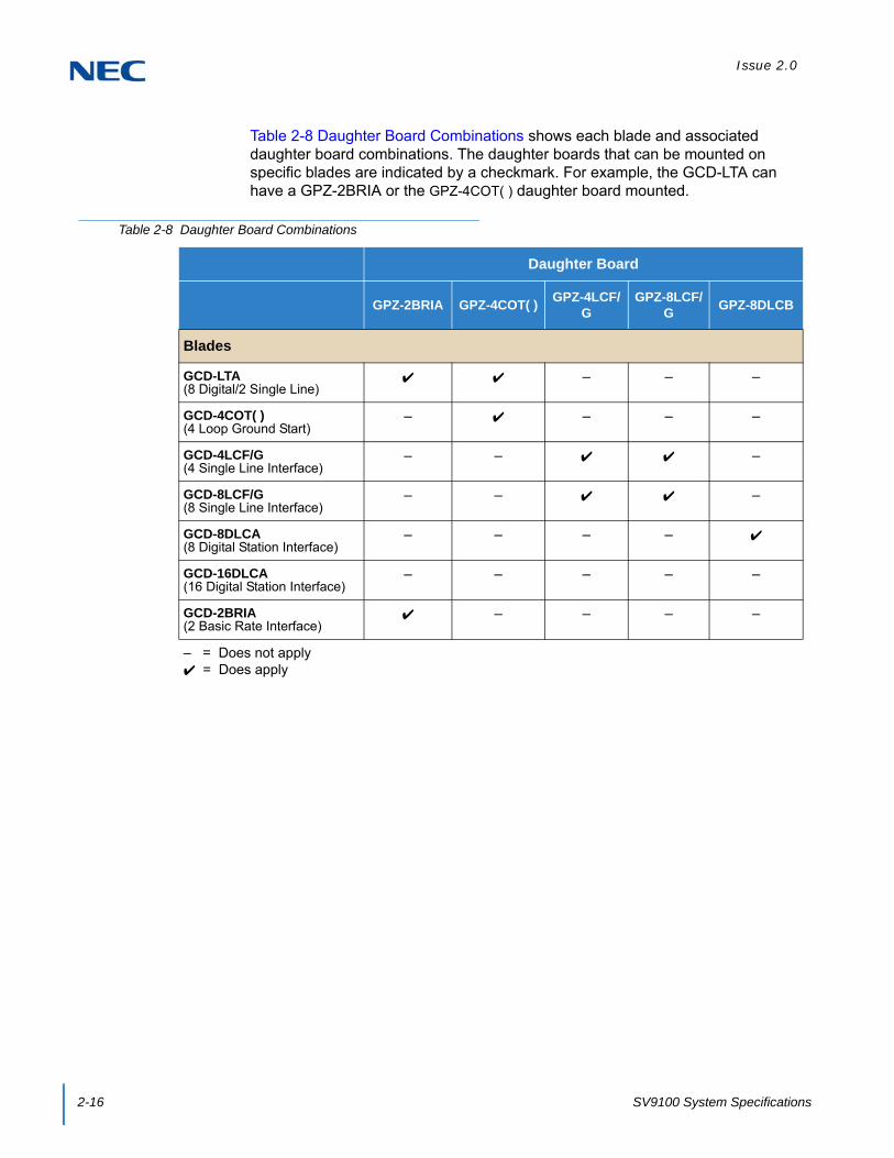
Issue 2.0
2-16 SV9100 System Specifications
Table 2-8 Daughter Board Combinations shows each blade and associated daughter board combinations. The daughter boards that can be mounted on specific blades are indicated by a checkmark. For example, the GCD-LTA can have a GPZ-2BRIA or the GPZ-4COT( ) daughter board mounted.
Table 2-8 Daughter Board Combinations
Daughter Board
GPZ-2BRIA GPZ-4COT( )GPZ-4LCF/
GGPZ-8LCF/
GGPZ-8DLCB
Blades
GCD-LTA(8 Digital/2 Single Line)
– – –
GCD-4COT( )(4 Loop Ground Start)
– – – –
GCD-4LCF/G(4 Single Line Interface)
– – –
GCD-8LCF/G(8 Single Line Interface)
– – –
GCD-8DLCA(8 Digital Station Interface)
– – – –
GCD-16DLCA(16 Digital Station Interface)
– – – – –
GCD-2BRIA(2 Basic Rate Interface)
– – – –
– = Does not apply = Does apply

Issue 2.0
SV9100 System Hardware Manual 2-17
SECTION 4 LICENSING
Table 2-9 License Information for Asia and Table 2-10 License Information for CALA provides a list of the licensing available with the system
Table 2-9 License Information for Asia
BEcode Item NameFeature Name
(WebPro/PCPro)Min Max Note
BE114067 SV9100 NETLINK NODE-01 LIC NetLink 1 49
-Netlink Node license (1-Node) with 32ch
VoIP resources.-This license is including the License codes; 0002: Netlink5103: VoIP Resource (1ch)-This license number is determined according to number of secondary site. So if 1 Primary and 3 Secondary site network, 3 licenses are needed. All license will be activated at Primary site.
BE114071 SV9100 HOTEL LIC Hotel/Motel On/OffHotel/Motel license (w/o PMS I/F)(License Code:0007)
BE114068 SV9100 ENCRYPTION LIC Encryption On/OffEncryption license (Except for China)(License Code:0030)
BE114081 SV9100 XMLPRO LIC XML Pro On/OffXML Pro API license(License Code:0041)
BE114070 SV9100 VIDEO MCU LIC Video MCU On/OffVideo MCU license (Simple MCU)(License Code:0042)
BE114072 SV9100 PMS LIC PMS On/OffHotel PMS I/F license(License Code:0046)
BE114073 SV9100 REMOTE CONF-01 LIC Remote Conference 1 20In-Conference Bridge (Remote Conf.)(License Code:0047)
BE114053 SV9100 HW MIGRATION LIC H/W migration On/OffHardware Migration license(License Code:0048)
BE114151 SV9100 MULTI DEVICE-01 LIC Multi Device 1 256Multi Device (Forking) (1 client)<R2>(License Code:0049)
BE114078 SV9100 1ST PARTY CTI-01 LIC 1st Party CTI (Ethernet) 1 2561st Party CTI (Ethernet)(License Code:0111)
BE114079 SV9100 3RD PARTY CTI LIC 3rd Party CTI Client On(999)/Off(0)
3rd Party CTI (System Wide)(License Code:0112)
BE114077 SV9100 OAI LIC OAI Activation On/OffOAI license (for BCT)(License Code:0123)
BE114042 SV9100 SYSTEM PORT-01 LIC System Port 1 1232Port Capacity license -System default: 64 ports(License Code:0300)

Issue 2.0
2-18 SV9100 System Specifications
BE114043 SV9100 VERSION LIC (R1) Version R1 On/OffSystem Version license for R1(License Code:0411)
BE114044 SV9100 VERSION LIC (R2) Version R2 On/OffSystem Version license for R2(License Code:0412)
BE114082 SV9100 INMAIL VRS PORT-01 LIC VRS Port 1 14
VRS Channel license (1ch)System default: 2 ports(License Code:1001)
BE114083 SV9100 INMAIL VM BOX-01 LIC VM Box 1 896InMail Box license (1 client)(License Code:1012)
BE114084 SV9100 IMAIL EMAIL CLT-01 LIC InMail Email Client 1 896InMail E-Mail Notification Client license (1 client) (License Code:1014)
BE114420 SV9100 UM8K FAX PORT-01 LIC UMS Fax Port 1 4UMS FAX Port license (1 port)(License Code:1402)
BE114418 SV9100 UM8K TTS PORT-01 LIC UMS TTS Port 1 61 Port of Text-to-Speech language for Microsoft outlook activation license.(License Code:1403)
BE114416 SV9100 UM8K UMS CLIENT-01 LIC UMS Client 1 891
UM8000 MAIL View App Session. Supports client View Mail, View Call Plus, VMM (Outlook), VML (Lotus Notes), VMG (GroupWise) and Web Mailbox Manager.This license now provides a UM8000 mailbox for the user.-System default: 5 clients(License Code:1404)
BE114417 SV9100 UM8K SYSTEM LANG-01 LIC UMS Multi-Language 1 22
-1 Language activation License.-System default: 3 languages(License Code:1406)
BE114421 SV9100 UM8K HOSPIT & PMS LIC UMS Hospitality and PMS On/Off
Hospitality and PMS activation license.(License Code:1407)
BE114422 SV9100 UM8K HOSPIT LANG-01 LIC UMS Hospitality Language 1 10
1 Hospitality Language activation license.(License Code:1408)
BE114423 SV9100 UM8K AMIS NETWORK LIC UMS Amis/Plus Net On/Off
UMS Amis/Plus Net (NETWORKING)(License Code:1409)
BE114419 SV9100 UM8K TTS LANG-01 LIC UMS TTS Language 1 101 Port of Text-to-Speech language activation license.(License Code:1410)
BE114074 SV9100 ACD AGENT-01 LIC ACD Client 1 896In-ACD client license(License Code:2002)
BE114075 SV9100 ACD P-EVENT LIC ACD P-event On/OffIn-ACD P-event license(License Code:2101)
BE114094 SV9100 ACD-MIS LIC ACD-MIS Basic On/OffACD-MIS Basic <Server> license(License Code:2102)
Table 2-9 License Information for Asia (Continued)
BEcode Item NameFeature Name
(WebPro/PCPro)Min Max Note

Issue 2.0
SV9100 System Hardware Manual 2-19
BE114095 SV9100 ACD-MIS MONITOR-01 LIC ACD-MIS Monitor 1 4
ACD-MIS Add Monitor license(License Code:2103)
BE114096 SV9100 ACD MIS AGENT-01 LIC ACD-MIS Agent 1 200ACD-MIS Agent Client license(License Code:2104)
BE114076 SV9100 ACD SKILL/CID BASE LIC ACD Advance On/Off
In-ACD Skill base / CID base routing license (License Code:2105)
BE114152 SV9100 ACD WHISPERING LIC ACD Whispering On/OffIn-ACD whispering license <R2>(License Code:2106)
BE114080 SV9100 CTI OCX LIC CTI-OCX On/OffCTI OCX license(License Code:3400)
BE114065 SV9100 IP TRUNK-01 LIC IP Trunk 1 396
IP Trunk (SIP/H323) license (1 Port) w/ 1ch VoIP resourcesThis license is including;5001: IP Trunk (SIP/h.323)(1 port)5103: VoIP Resource (1ch)–Up to four IP Trunk ports license are initially bundled on the IPLE.
BE114066 SV9100 NETWORKING-01 LIC K-CCIS over IP 1
K-CCIS:400
Aspire Net: 256
K-CCIS over IP / AspireNet over IP license (1 Port) w/ 1ch VoIP resources- K-CCIS : must be included to the Port Capacity- AspireNet : No need to be included to the Port CapacityThis license is including;5012: K-CCIS over IP5091:AspireNet over IP5103: VoIP Resource (1ch)Each system need this license to specify suitable AspireNet/K-CCIS over IP channel (Trunk) number.
BE114054 SV9100 IP PHONE-01 LIC IP Terminal 1 892
This license is including;5111: IP Terminal (SIP-MLT/Std-SIP/Softphone)(1 port)5103: VoIP Resource (1ch)–Up to four IP Terminal licenses are initially bundled on the IPLE.
BE114055 SV9100 MOBILE EXT-01 LIC Mobile Extension 1 892Mobile Extension license (1 port)-System default: 4 ports(License Code:5201)
BE114058 SV9100 SOFTPHONE-01 LIC UCS SoftPhone Client 1 256
IP Softphone Client license (1 client)This license is including;5301: UCS Soft Phone (SP310)5303: UCS Soft Phone Enhance
Table 2-9 License Information for Asia (Continued)
BEcode Item NameFeature Name
(WebPro/PCPro)Min Max Note

Issue 2.0
2-20 SV9100 System Specifications
BE114059 SV9100 SP WITH DT-01 LIC UCS SoftPhone Enhanced 1 256
Desktop Client with IP Softphone (1 client)This license is including;5301: UCS Soft Phone (SP310)5303: UCS Soft Phone Enhance5305: UCS Desktop (DT) Client
BE114056 SV9100 DT CLIENT-01 LIC UCS Client 1 256UCS Client license(1 client)(License Code:5305)
BE114060 SV9100 SHARED SVC-01 LIC UCS Shared Service 1 512
This license (Client based) is including;5304: UCS Attendant Client (System wide BLF, Phone Messaging, Changing others presence, Park Monitoring)5309: UCS Enhancement I (Presence, IM, Shared Directory, Change InMail greeting with presence)0112: 3rd Party CTI Client
BE114061 SV9100 BASIC SHARED SVC-01 LIC UCS Basic Shared Service 1 512
This license is including;5309: UCS Enhancement I (Presence, IM, Shared Directory, Change InMail greeting with presence)0112: 3rd Party CTI Client
BE114062 SV9100 CRM INTEGRATION-01 LIC UCS CRM Integration 1 256
This will support external CRM applications. Refer to the UC Suite Installation manual for further details.(License Code:5310)
BE114063 SV9100 INMAIL INT-01 LIC UCS InMail Integration 1 512Access to In Mail function from Desktop Suite. Client base License.(License Code:5312)
BE114057 SV9100 WEB DT CLIENT-01 LIC UCS Web Client 1 512Web DT Client (1 client)(License Code:5313)
BE114099 SV9100 PVA-PMS EU LIC PVA-PMS EU On/OffPVA-PMS license (License Code:6202)-This license is for Asia (except China) only. (FIAS 2.11base)
BE114097 SV9100 RGA CONF PORT-08 LIC RGA Conference 1 4
RGA Conference Channel (8 ports)(License Code:6300)
BE114424 SV9100 RGA CONF ENH I-LIC RGA-CNF Enhancement I On/OffRGA Conference Enhance I (Conf REC) license (License Code:6301)
BE114425 SV9100 RGA CONF LANG-01 LIC RGA Language license 1 57
RGA Multi-language license(License Code:6304)-System default: 3 languages
Table 2-9 License Information for Asia (Continued)
BEcode Item NameFeature Name
(WebPro/PCPro)Min Max Note

Issue 2.0
SV9100 System Hardware Manual 2-21
BE114532 SV9100 STANDARD USER-01 OT LIC 1 512
Standard User is including;
-BE114054(5111/5103): SV9100 IP PHONE-01 LIC
-BE114056(5305): SV9100 DT CLIENT-01 LIC
-BE114055(5201): SV9100 MOBILE EXT-01 LIC
BE114533 SV9100 STD PLUS USER-01 OT LIC 1 512
Standard Plus User is including;
-BE114054(5111/5103): SV9100 IP PHONE-01 LIC
-BE114083(1012): SV9100 INMAIL VM BOX-01 LIC
-BE114055(5201): SV9100 MOBILE EXT-01 LIC
-BE114056(5305): SV9100 DT CLIENT-01 LIC
-BE114057(5313): SV9100 WEB DT CLIENT-01 LIC
-BE114063(5312): SV9100 INMAIL INT-01 LIC
-BE114061(5309/0112): SV9100 BASIC SHARED SVC-01 LIC
BE114534 SV9100 PREMIUM USER-01 OT LIC 1 256
Premium User is including;
-BE114054(5111/5103): SV9100 IP PHONE-01 LIC (x 2 pcs)
-BE114083(1012): SV9100 INMAIL VM BOX-01 LIC
-BE114084(1014): SV9100 INMAIL EMAIL CLT-01 LIC
-BE114055(5201): SV9100 MOBILE EXT-01 LIC
-BE114056(5305): SV9100 DT CLIENT-01 LIC
-BE114057(5313): SV9100 WEB DT CLIENT-01 LIC
-BE114063(5312): SV9100 INMAIL INT-01 LIC
-BE114060(5304/5309/0112): SV9100 SHARED SVC-01 LIC
-BE114062(5310): SV9100 CRM INTEGRATION-01 LIC
-BE114151(0049) SV9100 MULTI DEVICE-01 LIC
Table 2-9 License Information for Asia (Continued)
BEcode Item NameFeature Name
(WebPro/PCPro)Min Max Note

Issue 2.0
2-22 SV9100 System Specifications
Table 2-10 License Information for CALA
BEcode/Stock No.
Item NameFeature Name
(WebPro/PCPro)Min Max Note
BE114067 641133
SV9100 NETLINK NODE-01 LIC LA NetLink 1 49
-Netlink Node license (1-Node) with 32ch
VoIP resources.-This license is including;0002: Netlink5103: VoIP Resource (1ch)-This license number is determined according to number of secondary site. So if 1 Primary and 3 Secondary site network, 3 licenses are needed. All license will be activated at Primary site.
BE114071641122 SV9100 HM-LIC LA Hotel/Motel On/Off
Hotel/Motel license (w/o PMS I/F)(License Code:0007)
BE114068641117 SV9100 ENCRYPTION LIC LA Encryption On/Off
Encryption license(License Code:0030)
BE114081641157 SV9100 XMLPRO LIC XML Pro On/Off
XML Pro API license(License Code:0041)
BE114070641118 SV9100 VIDEO MCU LIC LA Video MCU On/Off
Video MCU license (Simple MCU)(License Code:0042)
BE114072641119 SV9100 PMS LIC LA PMS On/Off
Hotel PMS I/F license(License Code:0046)
BE114073641120
SV9100 REMOTE CNF-01 LIC LA Remote Conference 1 20
In-Conference Bridge (Remote Conf.)(License Code:0047)
BE114053641121 SV9100 HW MIGRATION LIC LA H/W migration On/Off
Hardware Migration license(License Code:0048)
BE114151 641155
SV9100 MULTI DEVICE-01 LIC LA Multi Device 1 256
Multi Device (Forking) (1 client)<R2>(License Code:0049)
BE114078641127
SV9100 1ST PARTY CTI-01 LIC LA 1st Party CTI (Ethernet) 1 256
1st Party CTI (Ethernet)(License Code:0111)
BE114079641128
SV9100 3RD PARTY CTI-01 LIC LA 3rd Party CTI Client On(999)/
Off(0)3rd Party CTI (System Wide)(License Code:0112)
BE114077641156 SV9100 OAI LIC LA OAI Activation On/Off
OAI license (for BCT)(License Code:0123)
BE114042641110 SV9100 RESOURCE-01 LIC LA System Port 1 1232
Port Capacity license -System default: 64 ports(License Code:0300)
BE114044641100 SV9100 VERSION LIC(R2) LA Version R2 On/Off
System Version license for R2(License Code:0412)
BE114082641136
SV9100 I-ML VRS PORT-01 LIC LA VRS Port 1 14
VRS Channel license (1ch)System default: 2 ports(License Code:1001)

Issue 2.0
SV9100 System Hardware Manual 2-23
BE114083641137 SV9100 I-ML VM BOX-01 LIC LA VM Box 1 896
InMail Box license (1 client)(License Code:1012)
BE114084641138 SV9100 I-ML EML CLT-01 LIC LA InMail Email Client 1 896
InMail E-Mail Notification Client license (1 client) (License Code:1014)
BE114420640824 SV91 UM8K FAX PORT LIC-1 UMS Fax Port 1 4
UMS FAX Port license (1 port)(License Code:1402)
BE114418640825 SV91 UM8K TTS PORT LIC-1 UMS TTS Port 1 6
1 Port of Text-to-Speech language for Microsoft outlook activation license.(License Code:1403)
BE114416640823 SV91 UM8K UMS CLIENT LIC-1 UMS Client 1 891
UM8000 MAIL View App Session. Supports client View Mail, View Call Plus, VMM (Outlook), VML (Lotus Notes), VMG (GroupWise) and Web Mailbox Manager.This license now provides a UM8000 mailbox for the user.-System default: 5 clients(License Code:1404)
BE114417640826 SV91 UM8K LANG LIC-1 UMS Multi-Language 1 25
-1 Language activation License.-System default: 3 languages(License Code:1406)
BE114421640827 SV91 UM8K HOTEL & PMS LIC UMS Hospitality and PMS On/Off
Hospitality and PMS activation license.(License Code:1407)
BE114422640828
SV91 UM8K HOTEL LANGUAGE LIC-1 UMS Hospitality Language 1 10
1 Hospitality Language activation license.(License Code:1408)
BE114423640829
SV91 UM8K AMIS NETWORK LIC UMS Amis/Plus Net On/Off
UMS Amis/Plus Net (NETWORKING)(License Code:1409)
BE114419640830 SV91 UM8K TTS LANG LIC-1 UMS TTS Language 1 10
1 Port of Text-to-Speech language activation license.(License Code:1410)
BE114074641125 SV9100 CC AGENT-01 LIC LA ACD Client 1 896
In-ACD client license(License Code:2002)
BE114075641126 SV9100 CC P-EVENT LIC LA ACD P-event On/Off
In-ACD P-event license(License Code:2101)
BE114094641158 SV9100 ACD-MIS LIC LA ACD-MIS Basic On/Off
ACD-MIS Basic <Server> license(License Code:2102)
BE114095 641160
SV9100 ACD-MIS MONIT-01 LIC LA ACD-MIS Monitor 1 4
ACD-MIS Add Monitor license(License Code:2103)
BE114096641161
SV9100 ACD MIS AGENT-01 LIC LA ACD-MIS Agent 1 200
ACD-MIS Agent Client license(License Code:2104)
BE114076641123 SV9100 CC SKILL/CID LIC LA ACD Advance On/Off
In-ACD Skill base / CID base routing license (License Code:2105)
Table 2-10 License Information for CALA (Continued)
BEcode/Stock No.
Item NameFeature Name
(WebPro/PCPro)Min Max Note

Issue 2.0
2-24 SV9100 System Specifications
BE114152641159
SV9100 ACD WHISPERING LIC LA ACD Whispering On/Off
In-ACD whispering license <R2>(License Code:2106)
BE114080641150 SV9100 CTI OCX LIC LA CTI-OCX On/Off
CTI OCX license(License Code:3400)
BE114065641131 SV9100 SIP TRUNK-01 LIC LA IP Trunk 1 396
This license is including;5001: IP Trunk (SIP/h.323) (1 port)5103: VoIP Resource (1ch)–Up to four IP Trunk ports license are initially bundled on the IPLE.
BE114066641132 SV9100 NETWORKING-LIC LA K-CCIS over IP 1
K-CCIS:400
Aspire Net: 256
K-CCIS over IP / AspireNet over IP license (1 Port) w/ 1ch VoIP resources- K-CCIS : must be included to the Port Capacity- AspireNet : No need to be included to the Port CapacityThis license is including;5012: K-CCIS over IP5091:AspireNet over IP5103: VoIP Resource (1ch)Each system need this license to specify suitable AspireNet/K-CCIS over IP channel (Trunk) number.
BE114054641130 SV9100 IP CLIENT-01 LIC LA IP Terminal 1 892
This license is including;5111: IP Terminal (SIP-MLT/Std-SIP/Softphone)(1 port)5103: VoIP Resource (1ch)–Up to four IP Terminal licenses are initially bundled on the IPLE.
BE114055641129 SV9100 MOBILE EXT-01 LIC LA Mobile Extension 1 892
Mobile Extension license (1 port)-System default: 4 ports(License Code:5201)
BE114058641144
SV9100 S-PHONE CNT-01 LIC LA UCS SoftPhone Client 1 256
This license is including;5301: UCS Soft Phone (SP310)5303: UCS Soft Phone Enhance
BE114059641145
SV9100 UCS SP E CNT-01 LIC LA UCS SoftPhone Enhanced 1 256
This license is including;5301: UCS Soft Phone (SP310)5303: UCS Soft Phone Enhance5305: UCS Desktop (DT) Client
BE114056641140 SV9100 UCS CLIENT-01 LIC LA UCS Client 1 256
UCS Client license(1 client)(License Code:5305)
Table 2-10 License Information for CALA (Continued)
BEcode/Stock No.
Item NameFeature Name
(WebPro/PCPro)Min Max Note

Issue 2.0
SV9100 System Hardware Manual 2-25
BE114060 641146
SV9100 UCS ADV SERV-01 LIC LA
UCS Shared Service (Client based)
1 512
This license is including;5304: UCS Attendant Client (System wide BLF, Phone Messaging, Changing others presence, Park Monitoring)5309: UCS Enhancement I (Presence, IM, Shared Directory, Change InMail greeting with presence)0112: 3rd Party CTI Client
BE114061641147 SV9100 UCS ATT CNT-01 LIC LA UCS Basic Shared Service 1 512
This license is including;5309: UCS Enhancement I (Presence, IM, Shared Directory, Change InMail greeting with presence)0112: 3rd Party CTI Client
BE114062641141
SV9100 UCS CRM INTEG-01 LIC LA UCS CRM Integration 1 256
This will support external CRM applications. Refer to the UC Suite Installation manual for further details.(License Code:5310)
BE114063641142 SV9100 UCS V-ML INT-01 LIC LA UCS InMail Integration 1 512
Access to In Mail function from Desktop Suite. Client base License.(License Code:5312)
BE114057641143
SV9100 UCS WEB CLT-01 LIC LA UCS Web Client 1 512
Web DT Client (1 client)(License Code:5313)
BE114098640819 SV9100 PVA-PMS US LIC LA PVA-PMS On/Off
PVA-PMS license (NEC PMS 60/90) (License Code:6201)
BE114097641134
SV9100 RGA CONF PORT-01 LIC LA RGA Conference 1 4
RGA Conference Channel (8 ports)(License Code:6300)
BE114424641135
SV9100 RGA ENHANCE-01 LIC LA RGA-CNF Enhancement I On/Off
RGA Conference Enhance I (Conf REC) license (License Code:6301)
BE114425641162
SV9100 RGA CONF LANG-01 LIC LA RGA Language license 1 57
RGA Multi-language license(License Code:6304)-System default: 3 languages
BE114716641112
SV9100 STANDARD USER-01 LIC LA 1 896
Standard User is including;
-BE114670(5201): SV9100 MOBILE EXT-01 LIC LA
-BE114694(1012): SV9100 I-ML VM BOX-01 LIC LA
-BE114695(1014): SV9100 I-ML EML CNT-01 LIC LA
Table 2-10 License Information for CALA (Continued)
BEcode/Stock No.
Item NameFeature Name
(WebPro/PCPro)Min Max Note

Issue 2.0
2-26 SV9100 System Specifications
BE114717641113 SV9100 STD-P USER-01 LIC LA 1 512
Standard Plus User is including;
-BE114670(5201): SV9100 MOBILE EXT-01 LIC LA
-BE114694(1012): SV9100 I-ML VM BOX-01 LIC LA
-BE114695(1014): SV9100 I-ML EML CNT-01 LIC LA
-BE114672(5305): SV9100 UCS CLIENT-01 LIC LA
-BE114673(5313): SV9100 UCS WEB CNT-01 LIC LA
-BE114679(5312): SV9100 UCS V-ML INT-01 LIC LA
-BE114677(5309): SV9100 UCS ATT CNT-01 LIC LA
BE114718641114 SV9100 PREM USER-01 LIC LA 1 256
Premium User is including;
-BE114670(5201): SV9100 MOBILE EXT-01 LIC LA
-BE114694(1012): SV9100 I-ML VM BOX-01 LIC LA
-BE114695(1014): SV9100 I-ML EML CNT-01 LIC LA
-BE114672(5305): SV9100 UCS CLIENT-01 LIC LA
-BE114673(5313): SV9100 UCS WEB CNT-01 LIC LA
-BE114679(5312): SV9100 UCS V-ML INT-01 LIC LA
-BE114676(5304/5309/0112): SV9100 UCS ADV SERV-01 LIC LA
-BE114678(5310): SV9100 UCS CRM INTEG-01 LIC LA
Table 2-10 License Information for CALA (Continued)
BEcode/Stock No.
Item NameFeature Name
(WebPro/PCPro)Min Max Note

Issue 2.0
SV9100 System Hardware Manual 2-27
SECTION 5 POWER-BASED CALCULATOR CHART
The Univerge SV9100 system uses two types of power factors. For a single chassis chart refer to Table 2-10 Board Power Factor Chart. For the maximum number of specific blades per package, see Table 2-11 Maximum Number of Packages Installed. Refer to Table 2-12 Terminal Power Factor Chart below, for the Terminal/ Adapter power chart.
Table 2-11 Board Power Factor Chart
Board Power Factor
Total =<7
Item Power Factor
GCD-CP10 1
GCD-VM00 2
GCD-ETIA 2
GCD-PVAA 1
GPZ-IPLE 2
GCD-RGA 1
Table 2-12 Maximum Number of Packages Installed
Board(Power Factor)
Maximum Number of Packages Installed
9.5 inch with CPU
19 inch with CPU
19 inch without
CPU4 x 19 inch
GCD-ETIA (2) 2 3 3 12
GCD-PVAA (1) 2 5 6 23
GCD-RGA (1) 1 1 1 1

Issue 2.0
2-28 SV9100 System Specifications
Table 2-13 Terminal Power Factor Chart
Terminal Power Factor
19 inch Metal Chassis with Fan =<809.5 inch Plastic Chassis without Fan =<64
Item Power Factor
DTZ-12/24D-3 TEL/DTL-12/24D-1 TEL 0.8
DTZ-8LD-3 TEL/DTL-8LD-1 TEL 0.8
DTZ-2E-3 TEL/DTL-2E-1 TEL 0.8
DTZ-6DE-3 TEL/DTL-6DE-1 TEL 0.8
BHA-L UNIT 2
ADA-L UNIT 2
APR-L UNIT 2
BCH-L (BK) UNIT 2
BCA-Z UNIT 2
PSA-L UNIT 1.2
8LK-Z/16LK-Z/8LK-L UNIT 0
DCZ-60-2/DCL-60-1 CONSOLE 2
ITL-320C-1 TEL/ITL-320C-2 TEL 6
ITZ-12/24D-3 TEL/ITL-12/24D-1 TEL 4
ITL-2E-1 TEL 4
ITL-6DE-1 TEL 4
ITZ-12/24CG-3 TEL/ITL-12/24CG-3 TEL
4
ITZ-12/24DG-3 TEL/ITL-12/24DG-3 TEL
4
ITZ-8LDG-3 TEL 4
SLT (-24V) 0.8
SLT (-48V) 2
PGDAD 2
IP3WW-IPCDH 8
ITL factors are calculated using the GCD-ETIA blade.
Power requirements for the 9.5 “ chassis are the same as the 19” chassis.

Issue 2.0
SV9100 System Hardware Manual 2-29
Table 2-14 IP Terminal Power Factor Chart
IPTerminal
IEEE802.3af
Class
Label Indication(Maximum Current with All Options)
Maximum Current Without Options
48VDC 24VDC 48VDC 24VDC
ITL-12CG-3 TELITZ-12CG-3 TEL
Class 3 230mA 11.04W 450mA 10.8W 102mA 4.9W 192mA 4.62W
ITL-12DG-3 TELITZ-12DG-3 TEL
Class 3 230mA 11.04W 450mA 10.8W 102mA 4.9W 192mA 4.62W
ITL-2CR-1 TEL Class 3 180mA 8.64W 360mA 8.64W 96mA 4.6W 192mA 4.6W
ITL-320C-1 TEL/ITL-320C-2 TEL
Class 3 160mA 7.7W 290mA 7.0W 111mA 5.3W 192mA 4.6W
ITL-32D-1 TEL Class 2 130mA 6.2W 235mA 5.6W 90mA 4.3W 153mA 3.7W
ITL-8LD-1 TEL Class 2 130mA 6.2W 235mA 5.6W 81mA 3.9W 137mA 3.3W
ITL-24D-1 TEL Class 2 130mA 6.2W 235mA 5.6W 81mA 3.9W 137mA 3.3W
ITL-12D-1 TEL Class 2 130mA 6.2W 235mA 5.6W 81mA 3.9W 137mA 3.3W
ITL-24PA-1 TEL Class 2 130mA 6.2W 235mA 5.6W – 0.0W – 0.0W
ITL-24PD-1 TEL Class 2 130mA 6.2W 235mA 5.6W – 0.0W – 0.0W
ITL-24BT-1 TEL Class 2 130mA 6.2W 235mA 5.6W – 0.0W – 0.0W
ITZ-8LDG-3 TEL Class 2 125mA 6.0W 250mA 6.0W 92mA 4.4W 183mA 4.4W
ITZ-8LD-3 TEL Class 2 110mA 5.28W 217mA 5.21W 77mA 3.7W 154mA 3.7W
ITZ-24D-3 TEL Class 2 110mA 5.28W 217mA 5.21W 77mA 3.7W 154mA 3.7W
ITZ-12D-3 TEL Class 2 110mA 5.28W 217mA 5.21W 77mA 3.7W 154mA 3.7W
ITL-6DE-1 TEL Class 1 68mA 3.3W 122mA 2.9W 68mA 3.3W 122mA 2.9W
ITL-2E-1 TEL Class 1 68mA 3.3W 122mA 2.9W 68mA 3.3W 122mA 2.9W
Label Indication:IP Value/Sophisticated – Maximum watts when adding options or modular upgrades.IP Value – Maximum watts when ITL-12D-1 TEL/ITZ-12D-3 TEL is changed to ITL-8LD-1 TEL/ITZ-8LD-3 TEL or ITL-24D-1 TEL/ITZ-24D-3 TEL.

Issue 2.0
2-30 SV9100 System Specifications
Table 2-15 IEEE802.af Class Specifications
IEEE802.3af Minimum Maximum
Class 4 – –
Class 3 6.49W 12.95W
Class 2 3.84W 6.49W
Class 1 0.44W 3.84W
Class 0 0.44W 12.95W
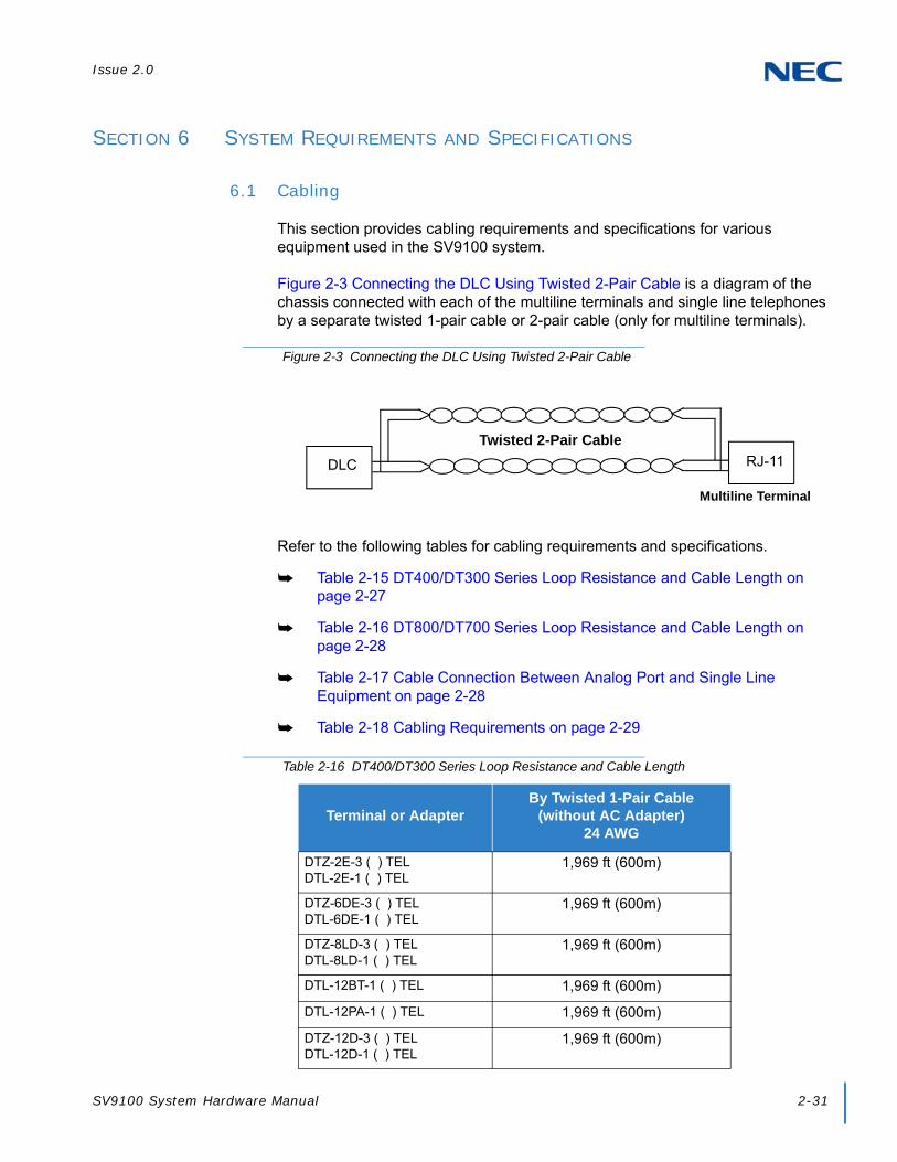
Issue 2.0
SV9100 System Hardware Manual 2-31
SECTION 6 SYSTEM REQUIREMENTS AND SPECIFICATIONS
6.1 Cabling
This section provides cabling requirements and specifications for various equipment used in the SV9100 system.
Figure 2-3 Connecting the DLC Using Twisted 2-Pair Cable is a diagram of the chassis connected with each of the multiline terminals and single line telephones by a separate twisted 1-pair cable or 2-pair cable (only for multiline terminals).
Refer to the following tables for cabling requirements and specifications.
Table 2-15 DT400/DT300 Series Loop Resistance and Cable Length on page 2-27
Table 2-16 DT800/DT700 Series Loop Resistance and Cable Length on page 2-28
Table 2-17 Cable Connection Between Analog Port and Single Line Equipment on page 2-28
Table 2-18 Cabling Requirements on page 2-29
Figure 2-3 Connecting the DLC Using Twisted 2-Pair Cable
Table 2-16 DT400/DT300 Series Loop Resistance and Cable Length
Terminal or AdapterBy Twisted 1-Pair Cable
(without AC Adapter)24 AWG
DTZ-2E-3 ( ) TELDTL-2E-1 ( ) TEL
1,969 ft (600m)
DTZ-6DE-3 ( ) TELDTL-6DE-1 ( ) TEL
1,969 ft (600m)
DTZ-8LD-3 ( ) TELDTL-8LD-1 ( ) TEL
1,969 ft (600m)
DTL-12BT-1 ( ) TEL 1,969 ft (600m)
DTL-12PA-1 ( ) TEL 1,969 ft (600m)
DTZ-12D-3 ( ) TELDTL-12D-1 ( ) TEL
1,969 ft (600m)
Multiline Terminal
Twisted 2-Pair Cable
DLC RJ-11

Issue 2.0
2-32 SV9100 System Specifications
DTZ-24D-3( ) TELDTL-24D-1( ) TEL
1,969 ft (600m)
DTL-32D-1 ( ) TEL 1,969 ft (600m)
DCL-60-1/DCZ-60-2 Console 1,969 ft (600m)
An AC Adapter is required.
Table 2-17 DT800/DT700 Series Loop Resistance and Cable Length
Terminal or Adapter Ethernet Cable
ITL-2E-1 ( ) TEL Cat 5/Cat 6 Ethernet 328.1 ft (100m)
ITL-6DE-1 ( ) TEL Cat 5/Cat 6 Ethernet 328.1 ft (100m)
ITL-8LDE-1 ( ) TEL Cat 5/Cat 6 Ethernet 328.1 ft (100m)
ITZ-8LD-3 ( ) TELITL-8LD-1 ( ) TEL
Cat 5/Cat 6 Ethernet 328.1 ft (100m)
ITZ-12D-3 ( ) TELITL-12D-1 ( ) TEL
Cat 5/Cat 6 Ethernet 328.1 ft (100m)
ITZ-12CG-3 ( ) TELITL-12CG-3 ( ) TEL
Cat 5/Cat 6 Ethernet 328.1 ft (100m)
ITZ-12DG-3 ( ) TELITL-12DG-3 ( ) TEL
Cat 5/Cat 6 Ethernet 328.1 ft (100m)
ITL-12PA-1 ( ) TEL Cat 5/Cat 6 Ethernet 328.1 ft (100m)
ITZ-24D-3 ( ) TELITL-24D-1 ( ) TEL
Cat 5/Cat 6 Ethernet 328.1 ft (100 m)
ITL-32D-1 ( ) TEL Cat 5/Cat 6 Ethernet 328.1 ft (100m)
ITL-320C-1 ( ) TEL ITL-320C-2 ( ) TEL
Cat 5/Cat 6 Ethernet 328.1 ft (100m)
Table 2-16 DT400/DT300 Series Loop Resistance and Cable Length (Continued)
Terminal or AdapterBy Twisted 1-Pair Cable
(without AC Adapter)24 AWG
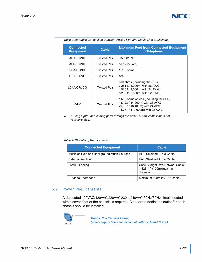
Issue 2.0
SV9100 System Hardware Manual 2-33
6.2 Power Requirements
A dedicated 100VAC/120VAC/220VAC/230 – 240VAC 50Hz/60Hz circuit located within seven feet of the chassis is required. A separate dedicated outlet for each chassis should be installed.
Table 2-18 Cable Connection Between Analog Port and Single Line Equipment
Connected Equipment
CableMaximum Feet from Connected Equipment
to Telephone
ADA-L UNIT Twisted Pair 9.5 ft (2.89m)
APR-L UNIT Twisted Pair 50 ft (15.24m)
PSA-L UNIT Twisted Pair 1,700 ohms
GBA-L UNIT Twisted Pair N/A
LCA/LCF/LCG Twisted Pair
600 ohms (Including the SLT)3,281 ft (1,000m) with 26 AWG4,920 ft (1,500m) with 24 AWG8,202 ft (2,500m) with 22 AWG
OPX Twisted Pair
1,500 ohms or less (Including the SLT)13,123 ft (4,000m) with 26 AWG20,997 ft (6,400m) with 24 AWG14,777 ft (10,600m) with 22 AWG
Mixing digital and analog ports through the same 25-pair cable runs is not recommended.
Table 2-19 Cabling Requirements
Connected Equipment Cable
Music on Hold and Background Music Sources Hi-Fi Shielded Audio Cable
External Amplifier Hi-Fi Shielded Audio Cable
ITZ/ITL Cabling Cat 5 Straight Data Network Cable – 328.1 ft (100m) maximum distance
IP Video Doorphone Maximum 100m (by LAN cable)
NOTE Double Pole/Neutral Fusing
(power supply fuses are located at both the L and N side).
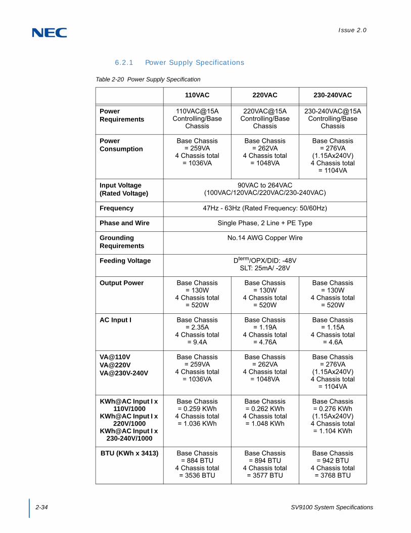
Issue 2.0
2-34 SV9100 System Specifications
6.2.1 Power Supply Specifications
Table 2-20 Power Supply Specification
110VAC 220VAC 230-240VAC
Power Requirements
110VAC@15A Controlling/Base
Chassis
220VAC@15A Controlling/Base
Chassis
230-240VAC@15A Controlling/Base
Chassis
Power Consumption
Base Chassis = 259VA
4 Chassis total = 1036VA
Base Chassis = 262VA
4 Chassis total = 1048VA
Base Chassis = 276VA
(1.15Ax240V)4 Chassis total
= 1104VA
Input Voltage (Rated Voltage)
90VAC to 264VAC(100VAC/120VAC/220VAC/230-240VAC)
Frequency 47Hz - 63Hz (Rated Frequency: 50/60Hz)
Phase and Wire Single Phase, 2 Line + PE Type
Grounding Requirements
No.14 AWG Copper Wire
Feeding Voltage Dterm/OPX/DID: -48VSLT: 25mA/ -28V
Output Power Base Chassis = 130W
4 Chassis total = 520W
Base Chassis = 130W
4 Chassis total = 520W
Base Chassis = 130W
4 Chassis total = 520W
AC Input I Base Chassis = 2.35A
4 Chassis total = 9.4A
Base Chassis = 1.19A
4 Chassis total = 4.76A
Base Chassis = 1.15A
4 Chassis total = 4.6A
VA@110VVA@220VVA@230V-240V
Base Chassis = 259VA
4 Chassis total = 1036VA
Base Chassis = 262VA
4 Chassis total = 1048VA
Base Chassis = 276VA
(1.15Ax240V)4 Chassis total
= 1104VA
KWh@AC Input I x 110V/1000
KWh@AC Input I x 220V/1000
KWh@AC Input I x 230-240V/1000
Base Chassis = 0.259 KWh
4 Chassis total = 1.036 KWh
Base Chassis = 0.262 KWh
4 Chassis total = 1.048 KWh
Base Chassis = 0.276 KWh(1.15Ax240V)4 Chassis total = 1.104 KWh
BTU (KWh x 3413) Base Chassis = 884 BTU
4 Chassis total = 3536 BTU
Base Chassis = 894 BTU
4 Chassis total = 3577 BTU
Base Chassis = 942 BTU
4 Chassis total = 3768 BTU

Issue 2.0
SV9100 System Hardware Manual 2-35
A dedicated outlet, separately fused and grounded for each chassis should be installed
6.2.2 Power Supply Consumption
Table 2-20 Power Consumption provides power consumption information for the SV9100 chassis.
6.3 Environmental Conditions
The equipment operating temperature and humidity conditions are provided in this section. Recommended long term environmental conditions are also provided.
6.3.1 Temperature and Humidity
Chassis, Telephones, BCH, BHA, 16LK, Console, ADA, APR
Operating Temperature: +32°F ~ +104°F (0°C ~ 40°C)
Recommended Long Term Temperature: -4°F ~ +140°F(-20°C ~ 60°C)
Operating Humidity: 10 ~ 90% RH (non-condensing)
IMPORTANT
Double Pole/Neutral Fusing(power supply fuses are located at both the L and N side).
Table 2-21 Power Consumption
Chassis VoltageMaximum
RMSCurrent
Watts Used (Idle)
Watts Used (Maximum)
Basic Chassis – GCD-CP10 Chassis
110VAC 2.35A
96 130220VAC 1.19A
230-240VAC 1.15A
Basic Chassis + Expansion Chassis
110VAC 4.7A
192 260220VAC 2.38A
230-240VAC 2.3A
Basic Chassis + 2 Expansion Chassis
110VAC 7.05A
288 390220VAC 3.57A
230-240VAC 3.45A
Basic Chassis + 3 Expansion Chassis
110VAC 9.4A
384 520220VAC 4.76A
230-240VAC 4.6A

Issue 2.0
2-36 SV9100 System Specifications
Recommended Long Term Humidity: 10 ~ 90% RH
Blades – GPZ-BS10, GPZ-BS11, GCD-8DLCA with GPZ-8DLCB Daughter Board, GCD-16DLCA
Operating Temperature: +32°F ~ +104oF (0oC ~ 40oC)
Recommended Long Term Temperature: -4°F ~ +140°F(-20°C ~ 60°C)
Humidity: 10 ~ 90% RH (non-condensing)
Recommended Long Term Humidity: 10 ~ 90% RH
Blades – GCD-4LCF/G with GPZ-4LCF/G Daughter Board, GCD-8LCF/G with GPZ-8LCF/G Daughter Board, GCD-4COT( ) with GPZ-4COT( ) Daughter Board, GCD-PRTA
Operating Temperature: +32°F ~ +104°F (0°C ~ 40°C)
Recommended Long Term Temperature: -4°F ~ +140°F(-20°C ~ 60°C)
Operating Humidity: 10 ~ 90% RH (non-condensing)
Recommended Long Term Humidity: 20 ~ 90% RH
Door Box
Operating Temperature: -4°F ~ +140oF (-20oC ~ 60oC
Operating Humidity: 20 ~ 80% (non-condensing)
SV9100 Power Supply – MPS7101
Operating Temperature: +32°F ~ +104°F (0oC ~ +40oC)
Recommended Long Term Temperature: -4F ~ 167oF(-40oC ~ 75oC)
Operating Humidity: 20 ~ 95% RH (non-condensing)
Recommended Long Term Humidity: 10 ~ 95% RH
Video Doorphone
Operating Temperature: +14°F ~ +113°F (-10oC ~ +45oC)
Storage Temperature: -4F ~ 140oF (-20oC ~ +60oC)
Operating Humidity: 90% or less (non-condensing)
Storage Humidity: 90% or less (non-condensing)
6.4 Outside Line Types
The following outside lines can be used with the UNIVERGE SV9100 system.
2-wire, Loop Start or Ground Start Trunks
2-wire, 2-way DID Lines (Dial Pulse or DTMF)

Issue 2.0
SV9100 System Hardware Manual 2-37
DID feature is not available for Europe and Australia market.
4-wire, E&M Tie Lines (Type I or V, Dial Pulse, or DTMF)
Digital Trunk T1/FT1 (Loop Start, Ground Start, Tie Line (E&M), or DID Signaling)
ISDN-BRI Trunks
ISDN-PRI Trunks
VoIP Trunks (Internet Protocols)

Issue 2.0
2-38 SV9100 System Specifications
6.5 Transmission, Network, and Control Specifications
6.5.1 Transmission
Data Length:
From multiline terminal to GCD-8DLCA: 23 bits
From GCD-8DLCA to multiline terminal: 23 bits
Data Transmission Rates:
Between GCD-8DLCA and multiline terminal: 184K bps (voice and signaling)
Scanning Time for each multiline terminal: 32ms.
6.5.2 Network
Time Division Multiplexing (TDM) allows transmission of data and voice simultaneously over one communications medium. The specifications that the UNIVERGE SV9100 system uses for switching, clock, data bus, and timeframe are shown below.
TDM Switching: PCM (u/A Law)
TDM Clock: 2.048 MHz
TDM Data Bus: 8-bit
TDM Timeframe: 125 µs.
6.5.3 Control
This section indicates the speed or capacity:
Control: Stored program with distributed processing
Central Processor: 32-bit microprocessor
Clock: P1015 processor 533 MHz
Interface Blade: 8- or 16-bit microprocessor
Optional Blades: 16- or 32-bit microprocessor
Multiline Terminal (TDM): 8-bit microprocessor
Multiline Terminal (IP): 32-bit microprocessor
IP Adapter: 32-bit microprocessor
Attendant Console: 4-bit microprocessor
PGD Adapter: 8-bit microprocessor

Issue 2.0
SV9100 System Hardware Manual 2-39
6.6 Dialing Specifications
6.6.1 Dial Pulse Address Signaling
Dial Pulse Address Signaling uses dial pulses (regular momentary interruptions) to signal the equipment. The following Dial Pulse specifications are used In the UNIVERGE SV9100 system.
Pulse Rate: 10 ± 0.5 pps/20 ± 1.0 pps
Percent Break: 60 ± 1.5%
Interdigit Interval: 0 pps/20 pps 770ms. ~ 830ms.
6.6.2 Dual-Tone Multifrequency (DTMF) Address Signaling
DTMF signaling includes push button or Touchtone dialing. When a key on a telephone is pushed, two tones (one high frequency and one low frequency) are provided. In the UNIVERGE SV9100 system, the following DTMF specifications are used.
Frequencies
Two sinusoidal frequencies are provided, one from the high frequency group and one from the low frequency group.
Frequency Deviation: Less than ±1.5%
Signal Level:
Nominal level per frequency: -6 ~ -4 dBm
Minimum level per frequency
Low Group: -10 dBm
High Group: -8 dBm
Maximum level per frequency: 0 dBm
Rise Time: Within 5ms.
Duration of Dual Frequency Signal:
110 ms. default/60ms. minimum
Interdigital Time: 140ms. default/45ms. minimum

Issue 2.0
2-40 SV9100 System Specifications
6.6.3 External Equipment Connection
Door Phone or TV Door Phone
External Speaker via amplifier
External music source for MOH and BGM
Tape recorder for voice recording via PGDAD
Door Lock/Release or General Purpose Relay via PGDAD
Printer for SMDR by LAN
PC by LAN
6.6.4 Music Source for Music on Hold via Chassis
Auxiliary Input: 0.6V PPS Signal Level
Input Impedance: 600
6.6.5 Music Source for Station Background Music via ACI
Auxiliary Input: 0.6V PPS Signal Level
Input Impedance: 600
6.6.6 External Paging (Audio)
Output Power: –10 dBm Signal Level
Output Impedance: 600
Relay Contact Rating: 500 mA, 24 Vdc
6.6.7 External Tone Ringer/Night Chime Output
Output Level: –10 dBm
Output Impedance: 600
Relay Contact Rating: 500 mA, 24 Vdc
1209 1336 1477
697 1 2 3
770 4 5 6
852 7 8 9
941 * 0 #
Nominal Low GroupFrequencies (Hz)
Nominal High GroupFrequencies (Hz)

Issue 2.0
SV9100 System Hardware Manual 2-41
6.6.8 SMDR Output
Female Connector (LAN)
6.6.9 PC Connection
Female Connector (LAN)
6.6.10 Relay Contact
All Relay Contact Ratings: 500 mA, 24Vdc
6.7 Battery Backup
The UNIVERGE SV9100 system has battery backup functions for system backup and for memory backup.
6.7.1 System Backup (Optional)
During a power failure, the CHS2UG can be backed up using the CHS2UG BATT MTG KIT for a backup time of 10 minutes or one of the CHSG LARGE BATT SETs for a backup time ranging from 45~180 minutes. The CHS2UG GW can be backed up using the CHS2UG B SMALL BATT BOX for a backup time of 10 minutes.
6.7.2 Memory Backup
The GCD-CP10 Blade battery retains the Clock/Calender and Last Number Redial (LNR) buffers for each station when the GCD-CP10 Blade encounters a power loss. With a fully charged battery, the settings are retained for about three years. The System Programmed memory (Customer Database) is stored in non-volatile Memory and can be erased only by a First Initialization. After power is restored, the system Blade returns to normal operation.

Issue 2.0
2-42 SV9100 System Specifications
6.8 Weights and Dimensions
Table 2-21 SV9100 Weights and Dimensions shows the shipping weight, height, width and depth of each SV9100 digital multiline terminal, IP multiline terminal, Dterm, chassis, assorted blades and adapters.
Table 2-22 SV9100 Weights and Dimensions
UnitShipping
Weight 1Height Width Depth
SV9100
CHS2UG 278.7 oz(7.9 kg)
3.47 in(88 mm)
16.9 in(430 mm)
16.08 in(409 mm)
CHS2UG GW 158.7 oz(4.5 kg)
4.57 in(116 mm)
8.47 in(215 mm)
14.53 in(369 mm)
CHS2UG B 158.7 oz(4.5 kg)
4.57 in(116 mm)
8.47 in(215 mm)
14.53 in(369 mm)
CHS2UG E 158.7 oz(4.5 kg)
4.57 in(116 mm)
8.47 in(215 mm)
14.53 in(369 mm)
GCD-CP10 7.06 oz(0.2 kg)
0.98 in(25 mm)
5.71 in(145 mm)
7.09 in(180 mm)
GCD-LTA 6.70 oz(0.19 kg)
0.98 in(25 mm)
5.71 in(145 mm)
7.09 in(180 mm)
CHSG LARGE BATT BOX 458.6 oz(13 kg)
5.24 in(133 mm)
16.93 in(430 mm)
14.3 in(363 mm)
CHSG LARGE BATT SET 194 oz(5.5 kg)
6.69 in(170 mm)
5.91 in(150 mm)
4.33 in(110 mm)
CHS2UG B SMALL BATT BOX(without batteries installed)
14.11 oz(0.4 kg)
1.42 in(36 mm)
10.87 in(276 mm)
8.45 in(214.7 mm)
CHS2UG B SMALL BATT SET 31.2 oz(0.88 kg)
5 in(127 mm)
5.75 in(146 mm)
4.75 in(120.6 mm)
Common
MPS7101 42.33 oz(1.2 kg)
2.36 in(60 mm)
7.08 in(180 mm)
6.10 in(155 mm)
GPZ-BS10 2.29 oz(.065 kg)
0.91 in(23 mm)
2.17 in(55 mm)
7.28 in(185 mm)
GPZ-BS11 1.975 oz(0.056 kg)
0.91 in(23 mm)
2.17 in(55 mm)
7.28 in(185 mm)
GPZ-IPLE 1.76 oz(0.05 kg)
0.71 in(18 mm)
2.6 in(66 mm)
5.4 in(138 mm)
GCD-8DLCA 5.89 oz(0.167 kg)
0.98 in(25 mm)
5.71 in(145 mm)
7.09 in(180 mm)
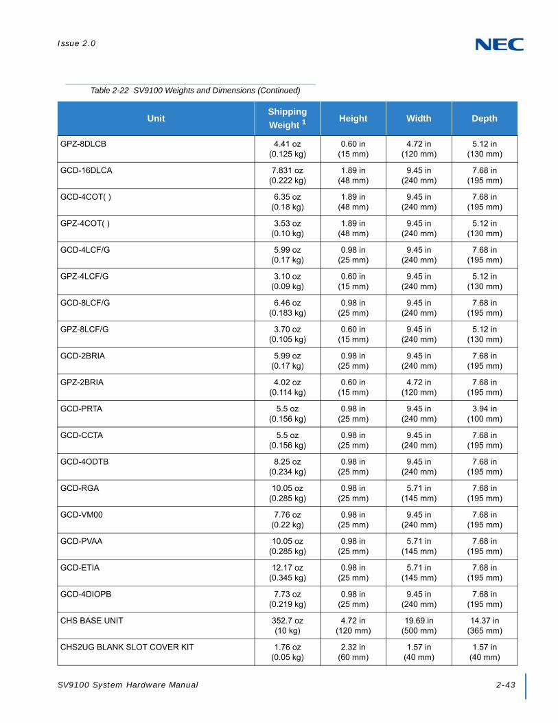
Issue 2.0
SV9100 System Hardware Manual 2-43
GPZ-8DLCB 4.41 oz(0.125 kg)
0.60 in(15 mm)
4.72 in(120 mm)
5.12 in(130 mm)
GCD-16DLCA 7.831 oz(0.222 kg)
1.89 in(48 mm)
9.45 in(240 mm)
7.68 in(195 mm)
GCD-4COT( ) 6.35 oz(0.18 kg)
1.89 in(48 mm)
9.45 in(240 mm)
7.68 in(195 mm)
GPZ-4COT( ) 3.53 oz(0.10 kg)
1.89 in(48 mm)
9.45 in(240 mm)
5.12 in(130 mm)
GCD-4LCF/G 5.99 oz(0.17 kg)
0.98 in(25 mm)
9.45 in(240 mm)
7.68 in(195 mm)
GPZ-4LCF/G 3.10 oz(0.09 kg)
0.60 in(15 mm)
9.45 in(240 mm)
5.12 in(130 mm)
GCD-8LCF/G 6.46 oz(0.183 kg)
0.98 in(25 mm)
9.45 in(240 mm)
7.68 in(195 mm)
GPZ-8LCF/G 3.70 oz(0.105 kg)
0.60 in(15 mm)
9.45 in(240 mm)
5.12 in(130 mm)
GCD-2BRIA 5.99 oz(0.17 kg)
0.98 in(25 mm)
9.45 in(240 mm)
7.68 in(195 mm)
GPZ-2BRIA 4.02 oz(0.114 kg)
0.60 in(15 mm)
4.72 in(120 mm)
7.68 in(195 mm)
GCD-PRTA 5.5 oz(0.156 kg)
0.98 in(25 mm)
9.45 in(240 mm)
3.94 in(100 mm)
GCD-CCTA 5.5 oz(0.156 kg)
0.98 in(25 mm)
9.45 in(240 mm)
7.68 in(195 mm)
GCD-4ODTB 8.25 oz(0.234 kg)
0.98 in(25 mm)
9.45 in(240 mm)
7.68 in(195 mm)
GCD-RGA 10.05 oz(0.285 kg)
0.98 in(25 mm)
5.71 in(145 mm)
7.68 in(195 mm)
GCD-VM00 7.76 oz(0.22 kg)
0.98 in(25 mm)
9.45 in(240 mm)
7.68 in(195 mm)
GCD-PVAA 10.05 oz(0.285 kg)
0.98 in(25 mm)
5.71 in(145 mm)
7.68 in(195 mm)
GCD-ETIA 12.17 oz(0.345 kg)
0.98 in(25 mm)
5.71 in(145 mm)
7.68 in(195 mm)
GCD-4DIOPB 7.73 oz(0.219 kg)
0.98 in(25 mm)
9.45 in(240 mm)
7.68 in(195 mm)
CHS BASE UNIT 352.7 oz(10 kg)
4.72 in(120 mm)
19.69 in(500 mm)
14.37 in(365 mm)
CHS2UG BLANK SLOT COVER KIT 1.76 oz(0.05 kg)
2.32 in(60 mm)
1.57 in(40 mm)
1.57 in(40 mm)
Table 2-22 SV9100 Weights and Dimensions (Continued)
UnitShipping
Weight 1Height Width Depth

Issue 2.0
2-44 SV9100 System Specifications
CHS L BATT BOX RACK MOUNT BRACKET 352.7 oz(10 kg)
18.5 in(470 mm)
14.6 in(370 mm)
2.76 in(70 mm)
CHS2UG INT BATT SET 95.24 oz(2.7 kg)
4.33 in(110 mm)
2.76 in(70 mm)
3.15 in(80 mm)
CHS2UG RACK MOUNT KIT 17.6 oz(0.5 kg)
0.91 in(23 mm)
9.65 in(245 mm)
3.35 in(85 mm)
CHS1UG/2UG WALL MOUNT KIT 35.27 oz(1 kg)
1.18 in(30 mm)
13.8 in(350 mm)
1.77 in(45 mm)
CHS2UG MOVABLE WALL MOUNT KIT 98.8oz(2 kg)
5.17 in(131.3 mm)
14.5 in(367.6 mm)
8.8 in(222.8 mm)
CHS2UG JOINT BRACKET KIT 7.06 oz(0.2 kg)
0.19 in(3 mm)
5.91 in(150 mm)
1.7 in(43 mm)
CHS2UG BATT MTG KIT 6 Slot 106 oz(3.0 kg)
2.95 in(75 mm)
4.45 in(113 mm)
4.13 in(105 mm)
IP5D-RACK MOUNT BAR SET 45.86 oz(1.3 kg)
2.40 in(61 mm)
18.9 in(480 mm)
0.47 in(12 mm)
Digital Multiline Terminal
DTL-2E-1 (BK) TEL 35.27 oz(1.0 kg)
4.41 in(112 mm)
7.05 in(179 mm)
8.86 in(225 mm)
DTL-6DE-1 (BK) TEL 38.8 oz(1.1 kg)
4.41 in(112 mm)
7.05 in(179 mm)
8.86 in(225 mm)
DTL-8LD-1 (BK) TELDTL-8LD-1 (WH) TEL
45.6 oz(1.3 kg)
4.41 in(112 mm)
7.05 in(179 mm)
10.39 in(264 mm)
DTL-12BT-1 (BK) TEL 45.6 oz(1.3 kg)
4.29 in(109 mm)
7.6 in(183 mm)
10.16 in(258 mm)
DTL-12PA-1 (BK) TEL 45.6 oz(1.3 kg)
4.41 in(112 mm)
7.6 in(183 mm)
10.16 in(258 mm)
DTL-12D-1 (BK) TELDTL-12D-1 (WH) TEL
42.33 oz(1.2 kg)
4.39 in(111.7 mm)
7.05 in(179 mm)
10.16 in(258 mm)
DTL-24D-1 (BK) TELDTL-24D-1 (WH) TEL
42.33 oz(1.2 kg)
4.39 in(111.7 mm)
7.05 in(179 mm)
10.16 in(258 mm)
DTL-32D-1 (BK) TELDTL-32D-1 (WH) TEL
45.6 oz(1.3 kg)
4.39 in(111.7 mm)
8.1 in(205.8 mm)
10.16 in(258 mm)
DTZ-2E-3 (BK) TEL 35.27 oz(1.0 kg)
4.41 in(112 mm)
7.05 in(179 mm)
8.86 in(225 mm)
DTZ-6DE-3 (BK) TEL 38.8 oz(1.1 kg)
4.41 in(112 mm)
7.05 in(179 mm)
8.86 in(225 mm)
DTZ-12D-3 (BK) TELDTZ-12D-3 (WH) TEL
42.33 oz(1.2 kg)
4.39 in(111.7 mm)
7.05 in(179 mm)
10.16 in(258 mm)
Table 2-22 SV9100 Weights and Dimensions (Continued)
UnitShipping
Weight 1Height Width Depth
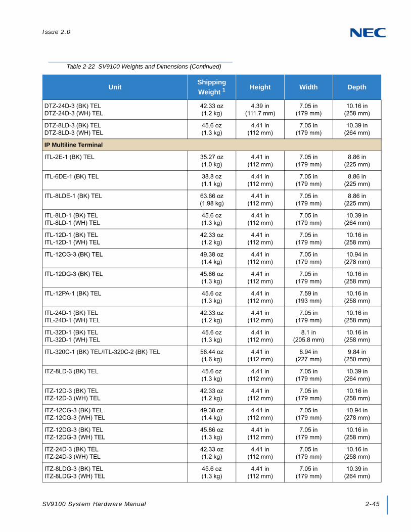
Issue 2.0
SV9100 System Hardware Manual 2-45
DTZ-24D-3 (BK) TELDTZ-24D-3 (WH) TEL
42.33 oz(1.2 kg)
4.39 in(111.7 mm)
7.05 in(179 mm)
10.16 in(258 mm)
DTZ-8LD-3 (BK) TELDTZ-8LD-3 (WH) TEL
45.6 oz(1.3 kg)
4.41 in(112 mm)
7.05 in(179 mm)
10.39 in(264 mm)
IP Multiline Terminal
ITL-2E-1 (BK) TEL 35.27 oz(1.0 kg)
4.41 in(112 mm)
7.05 in(179 mm)
8.86 in(225 mm)
ITL-6DE-1 (BK) TEL 38.8 oz(1.1 kg)
4.41 in(112 mm)
7.05 in(179 mm)
8.86 in(225 mm)
ITL-8LDE-1 (BK) TEL 63.66 oz(1.98 kg)
4.41 in(112 mm)
7.05 in(179 mm)
8.86 in(225 mm)
ITL-8LD-1 (BK) TELITL-8LD-1 (WH) TEL
45.6 oz(1.3 kg)
4.41 in(112 mm)
7.05 in(179 mm)
10.39 in(264 mm)
ITL-12D-1 (BK) TELITL-12D-1 (WH) TEL
42.33 oz(1.2 kg)
4.41 in(112 mm)
7.05 in(179 mm)
10.16 in(258 mm)
ITL-12CG-3 (BK) TEL 49.38 oz(1.4 kg)
4.41 in(112 mm)
7.05 in(179 mm)
10.94 in(278 mm)
ITL-12DG-3 (BK) TEL 45.86 oz(1.3 kg)
4.41 in(112 mm)
7.05 in(179 mm)
10.16 in(258 mm)
ITL-12PA-1 (BK) TEL 45.6 oz(1.3 kg)
4.41 in(112 mm)
7.59 in(193 mm)
10.16 in(258 mm)
ITL-24D-1 (BK) TELITL-24D-1 (WH) TEL
42.33 oz(1.2 kg)
4.41 in(112 mm)
7.05 in(179 mm)
10.16 in(258 mm)
ITL-32D-1 (BK) TELITL-32D-1 (WH) TEL
45.6 oz(1.3 kg)
4.41 in(112 mm)
8.1 in(205.8 mm)
10.16 in(258 mm)
ITL-320C-1 (BK) TEL/ITL-320C-2 (BK) TEL 56.44 oz(1.6 kg)
4.41 in(112 mm)
8.94 in(227 mm)
9.84 in(250 mm)
ITZ-8LD-3 (BK) TEL 45.6 oz(1.3 kg)
4.41 in(112 mm)
7.05 in(179 mm)
10.39 in(264 mm)
ITZ-12D-3 (BK) TELITZ-12D-3 (WH) TEL
42.33 oz(1.2 kg)
4.41 in(112 mm)
7.05 in(179 mm)
10.16 in(258 mm)
ITZ-12CG-3 (BK) TELITZ-12CG-3 (WH) TEL
49.38 oz(1.4 kg)
4.41 in(112 mm)
7.05 in(179 mm)
10.94 in(278 mm)
ITZ-12DG-3 (BK) TELITZ-12DG-3 (WH) TEL
45.86 oz(1.3 kg)
4.41 in(112 mm)
7.05 in(179 mm)
10.16 in(258 mm)
ITZ-24D-3 (BK) TELITZ-24D-3 (WH) TEL
42.33 oz(1.2 kg)
4.41 in(112 mm)
7.05 in(179 mm)
10.16 in(258 mm)
ITZ-8LDG-3 (BK) TELITZ-8LDG-3 (WH) TEL
45.6 oz(1.3 kg)
4.41 in(112 mm)
7.05 in(179 mm)
10.39 in(264 mm)
Table 2-22 SV9100 Weights and Dimensions (Continued)
UnitShipping
Weight 1Height Width Depth

Issue 2.0
2-46 SV9100 System Specifications
Optional
8LK-L (BK) UNIT8LK-L (WH) UNIT
7.05 oz(0.2 kg)
1.77 in(45 mm)
1.15 in(29.3 mm)
8.82 in(224 mm)
8LK-Z (BK) UNIT8LK-Z (WH) UNIT
7.05 oz(0.2 kg)
1.77 in(45 mm)
1.15 in(29.3 mm)
8.82 in(224 mm)
ADA-L UNIT 2.82 oz(0.08 kg)
0.98 in(25 mm)
2.56 in(65 mm)
2.84 in(72 mm)
APR-L UNIT 5.29 oz(0.15 kg)
0.98 in(25 mm)
2.56 in(65 mm)
2.84 in(72 mm)
BCH-L (BK) UNIT 31.75 oz(0.9 kg)
4.41 in(112 mm)
3.19 in(81 mm)
8.8 in(223 mm)
BHA-L UNIT 3.53 oz(0.1 kg)
0.98 in(25 mm)
2.56 in(65 mm)
2.84 in(72 mm)
BCA-Z UNIT 2.82 oz(0.08 kg)
0.98 in(25 mm)
2.56 in(65 mm)
2.84 in(72 mm)
IPLA-R UNIT 2.82 oz(0.08 kg)
0.98 in(25 mm)
2.24 in(57 mm)
3.94 in(100 mm)
PGDAD 12.4 oz(0.35 kg)
1.58 in(40 mm)
6.81 in(173 mm)
4.13 in(105 mm)
DCL-60-1 (BK) CONSOLEDCL-60-1 (WH) CONSOLE
21.16 oz(0.6 kg)
3.23 in(82 mm)
5.39 in(137 mm)
8.82 in(224 mm)
DCZ-60-2 (BK) CONSOLEDCZ-60-2 (WH) CONSOLE
27.50 oz(0.78 kg)
3.15 in(80 mm)
8.27 in(210 mm)
9.84 in(250mm)
DP-D-1A Doorphone 7.05 oz(0.2 kg)
5.12 in(130 mm)
3.89 in(98 mm)
1.12 in(28.5 mm)
PSA-L (BK) UNITPSA-L (WH) UNIT
10.58 oz(0.3 kg)
3.15 in(80 mm)
2.91 in(74 mm)
8.8 in(223 mm)
GBA-L UNIT 23.99 oz(0.68 kg)
5.9 in(150 mm)
7.05 in(179 mm)
6.34 in(161 mm)
AC-L UNIT 12 oz(0.34 kg)
1.10 in(28 mm)
1.77 in(45 mm)
3.98 in(101 mm)
WM-L UNIT 1.58 oz(0.045 kg)
0.996 in(25.3 mm)
3.996 in(101.5 mm)
4.92 in(125 mm)
DSS WM-L UNIT 1.41 oz(0.04 kg)
0.99 in(25.3 mm)
3.4 in(86.5 mm)
4.92 in(125 mm)
IP Video Doorphone 11.29 oz(0.32 kg)
5.9 in(150 mm)
3.94 in(100 mm)
2.1 in(53.5 mm)
1 Shipping weight includes the shipping carton.
Table 2-22 SV9100 Weights and Dimensions (Continued)
UnitShipping
Weight 1Height Width Depth

Issue 2.0
SV9100 System Hardware Manual 2-47
6.8.1 Tone Patterns
Table 2-22 Tone Patterns lists the frequency and the pattern for the tones. Tones are used to inform UNIVERGE SV9100 station users of system functions such as dial tone, busy tone, or ringback tone.
6.8.2 Multiline Terminal LED Flash Patterns
The UNIVERGE SV9100 system has several colored LEDs installed. Green is used primarily for I-Use conditions and for outside calls. Red is used primarily for Other Use conditions and internal calls.
The Large LED provides the user a variety of programmable colors and preferences. Refer to Table 2-23 Multiline Terminal LED Flash Pattern.

Issue 2.0
2-48 SV9100 System Specifications
Table 2-23 Tone Patterns
System Tone(Fixed)
Frequency (Hz)(Fixed)
Intermit(Default)
Cycle
Busy Tone 480/620 60 IPM
Call Waiting Tone 440 60 IPM
Second Dial Tone 350/440 120 IPM
Howler Tone 2400 Modulation (16 Hz) Continuous
Internal Dial Tone 350/440 Continuous
Internal Ringback Tone 440/480 1 sec On2 sec Off
LCR Dial Tone 440 Continuous
Reorder Tone 480/620 120 IPM
Service Set Tone 440 Continuous
Special Dial Tone 440 240 IPM
Tone Burst 1 Tone 440 Continuous
Tone Burst 2 Tone 620 Continuous
Tie/DID Ringback Tone 440/480 2 sec On4 sec Off
Camp-On ToneCall Alert NotificationAttendant Tone Override
440 Continuous
DIT Alert Tone 480/620 Continuous
Call Forward Alert ToneCall ForwardConfiguration Tone
350/440 120 IPM
0.5 sec
0.5 sec
0.5 sec
0.5 sec
0.25 sec
0.25 sec
1 sec
2 sec
0.25 sec
0.25 sec
0.125 sec
0.125 sec
1 sec
1 sec
2 sec4 sec
0.7 sec
0.5 sec
0.25 sec ON x 2~3

Issue 2.0
SV9100 System Hardware Manual 2-49
Table 2-24 Multiline Terminal LED Flash Pattern
LED Condition Color Flash Patterns
Line Key
I-UseBusyIncoming CallI-HoldCall HoldHold RecallTransfer RecallLive Monitoring ModeMessage Waiting on Line Key
GreenRedRedGreenRedGreenGreenGreenRed
Microphone ON Red
Mic ON (Series i) Red
Large LED 1
Incoming Internal CallIncoming Outside CallMessage from AttendantVoice Mail Message
RedGreenGreenRed
SpeakerONSystem Data Entry
RedRed
Answer
Incoming TrunkExclusive HoldUser Ringing Line PreferenceVoice Over with Broker’s Call
RedGreenRedGreen
Feature
Callback SetAuto Repeat SetON (to set function)Call FWD - All Calls Set
RedRedRedRed
BLF orDSS Key
Use, HoldDND, Call FWD-All Calls SetSpecial Mode (while pressing Feature or going off-line)
RedRedRed
1 The Large LED provides the user a variety of programmable colors and preferences.
0 0.5 1.0 1.5 2.0 sec.

Issue 2.0
2-50 SV9100 System Specifications
SECTION 7 TRAFFIC CAPACITY
Table 2-24 Traffic Capacity Chart provides information about the traffic capacity for the basic system package and expanded system package.
The GCD-CP10 provides:
400 trunk ports maximum
896 extension ports maximum
896 ports digital/IP extensions maximum
368 analog ports maximum
512 virtual extensions
Connection for GPZ-IPLE VoIP Daughter Board
Connection for Voice Mail SD Card (SD-A1/SD-B1)
Supports TAPI 1.x
One Green Status LED
Four Red Status LEDs
Five diagnostic LEDs which indicate the status of various system functions
During normal operation, the RUN LED is flashing and the remaining LEDs are off.
700x700 Time Division Multiplex Switch (TDM Switch)
Digital Phase Locked Loop (DPLL)
Table 2-25 Traffic Capacity Chart
Traffic Capacity Basic System PackageExpanded System
Package
Traffic Capacity (GCD-CP10) 9200 BHCA (Maximum) 9200 BHCA (Maximum)
This depends on traffic and configuration.

SV9100 System Hardware Manual 3-1
Chapter 3
UNIVERGE® SV9100
Installing the SV9100 Chassis
SECTION 1 GENERAL INFORMATION
This chapter contains information to help the technician install the chassis for the SV9100 system. The technician should be familiar with this section before installing any equipment.
SECTION 2 SITE PREPARATION AND MDF/IDF CONSTRUCTION
Pre-installation planning is essential. Advanced planning minimizes installation time, cost, and disruption of the customer business activities.
2.1 Precautionary Information:
Never install telephone wiring during a lightning storm.
Never install telephone jacks in wet locations unless the jack is specifically designed for wet locations.
Never touch uninsulated telephone wires or terminals unless the telephone line is disconnected at the network interface.
Use caution when installing or modifying telephone lines.
To avoid shock or equipment damage, do not plug in or turn the system power on before completing the installation process.
Avoid working with the equipment during electrical storms.
Use only commercial AC power to prevent shock or fire.
Use the power cord supplied for the chassis.
To prevent overheating, do not bundle AC power cords together.
Make sure the chassis has a proper earth ground.
Install batteries with the correct polarity to prevent damaging equipment.
To avoid damage, the chassis should not be placed on unstable surfaces.
WARNING
Observe the following warnings during installation.

Issue 2.0
3-2 Installing the SV9100 Chassis
Although it is recommended to install the blades with the system power off, all blades can be installed hot, except for the following:
GCD-CP10
GPZ-BS10 and GPZ-BS11
2.2 Surveying the Customer Site
In most cases, a survey of the customer site is necessary to determine the proper placement of the Main Distribution Frame (MDF), the exact dimensions of the area selected for the MDF, cabling requirements, and possible Intermediate Distribution Frame (IDF) locations.
The information obtained at the customer site can permit the installer to partially assemble the MDF before installation at the customer premise. This can reduce the time spent installing at the customer site and reduce downtime.
2.3 Selecting the Best Location for Proper Installation
2.3.1 Selecting the Chassis Installation Site
When selecting an installation site for the chassis, consider the following conditions to ensure proper installation:
Chassis are normally rack mounted to protect against accident or flooding.
The chassis should not be located directly beneath pipes. Leaks or condensation could damage the UNIVERGE SV9100 system equipment.
The area where the chassis is located must be free of corrosive and inflammable gases, excessive chemical or industrial dusts, and other materials that could cause a hazard to personnel or to the proper functioning of the equipment.
The operating ambient temperature and humidity must be within the limits specified in 6.3 Environmental Conditions on page 2-34 in Chapter 2 System Specifications.
The operation of the system is virtually noiseless and allows wide selection of installation sites. Take care to ensure the chassis or cabling does not present a hazard to office traffic. To minimize cabling costs, a centralized location must be chosen.
Locate the chassis at a site where a dedicated AC power source can be easily accessed.
Connect the chassis to a dedicated AC receptacle that is not being used for any other device.

Issue 2.0
SV9100 System Hardware Manual 3-3
2.3.2 Selecting a Permanent MDF Location
When selecting a permanent site for the MDF, the technician may encounter some of the following conditions:
Limited space is available but must be used.
The available space may pose one or more environmental hazards.
The proposed location has limitations such as insufficient lighting or the lack of a suitable ground for the chassis.
The technician that encounters these conditions must provide the best possible solution for installing the equipment. This document cannot cover all possible situations, precautions, and actions.
2.3.3 Selecting a Site for Installing the Telephones
When a site is being selected for telephone installation, consider the following conditions to ensure proper installation:
Ensure cable length and line resistance (loop), between the chassis and telephones, comply with the specifications listed.
Select a place where devices that require an external power supply can be connected easily to an AC outlet.
2.4 Constructing the Main Distribution Frame (MDF)
The Main Distribution Frame (MDF) has two different standard quick-connect terminal blocks that are mounted on a 3/4-inch plywood backboard. Mounting these blocks on standoffs for ease of access is recommended. The recommended blocks are 66B50 for termination of the MDF Cable Assembly and 66M50 for termination of the station cables.
The Intermediate Distribution Frame (IDF) requires the 66M50 blocks only.
Both the MDF and the IDF use standard bridging clips for each terminal block. The bridging clips mate the left half of the terminal block (terminated cable run) to the right half of the terminal block (cross connection wire) to the terminal block (cross connection wire). The bridging clips are also useful during troubleshooting to help isolate the cable runs and terminals/telephones from the central equipment and the Central Office Network from the system.
The CHS2UG chassis can be mounted on the wall, the floor, a stand or in a rack. The CHS2UG GW chassis can be mounted on the wall, a stand or in a rack. Plywood should first be installed on the wall where the chassis will be positioned, to allow for secure anchoring. It has a bracket, which can be used to secure each chassis in any installation. Ensure that enough space is available to allow the installation of the additional chassis above and below the Controlling Chassis.

Issue 2.0
3-4 Installing the SV9100 Chassis
The system requires a dedicated 100 - 240 VAC 50/60 Hz circuit located within seven feet of the AC receptacle. Telco should install the RJ21X to the right of the Controlling Chassis. Extension blocks should be installed to the left of the Controlling Chassis.
Chassis are shipped fully assembled. The following are included with the chassis:
19” Chassis (CHS2UG)
One black 3-prong power cord (packed outside the chassis)
CHS2UG RACK MOUNT KIT
9.5” Gateway Chassis (CHS2UG GW)
One black 3-prong power cord (packed outside the chassis)
Wall Mount Kit
Stand Mount Kit
9.5” Base and Expansion Chassis (CHS2UG B and CHS2UG E)
One black 3-prong power cord (packed outside the chassis)
Wall Mount Kit
Stand Mount Kit
2.5 Power Failure Transfer
The Power Failure Transfer relays are located on the COIU blades (CN3). When selecting a Single Line Telephone for power failure transfer, make sure it matches the CO line dialing type (10 pps, 20 pps, or DTMF) where it is connected. Each COIU blade supports two power failure transfer connections. During a power failure condition, CO Ports 1 and 2 on the COIU Blade are used for Power Failure Transfer relays 1 and 2 consecutively. Table 3-1 Power Failure Transfer Connections is a relay diagram. The relay is shown with the power ON.
NOTE
Power Failure and FAX Branch Connection do not function simultaneously on the same port. Use Program 14-02-21 (Fax Branch Connection) to enable this feature per trunk.
Table 3-1 Power Failure Transfer Connections
Pin Number Description Pin Number Description
1 Not in Use 2 Not in Use
3 Tip for Circuit 2 4 Ring for Circuit 1
5 Tip for Circuit 1 6 Ring for Circuit 2
7 Not in Use 8 Not in Use

Issue 2.0
SV9100 System Hardware Manual 3-5
2.6 Fax CO Branch Connection
The Fax Branch Connection feature uses the Power Failure Transfer relays located on the COIU Blades (CN3). Each COIU Blade supports two Fax CO Branch Connections.
SECTION 3 INSTALLING THE CHASSIS
3.1 Unpacking the Equipment
Inspect the equipment for any physical damage. If you are not sure about the function of a component, review the associated information within this manual. Contact your authorized NEC Sales Representative if you have additional questions. Note that the chassis does not initially contain any blades.
Make sure you have appropriate tools for the job, including: a test set, a punch down tool, and a digital voltmeter.
Ensure that you have a building plan showing common equipment, extensions, the Telco demarcation and earth ground location before you start installation. Be sure to properly plan your installation site and that you are familiar with the installation safety precautions. If you have not done that, please do so now. Refer to Section 2 Site Preparation and MDF/IDF Construction on page 3-1.
3.2 Before Installation
Before installing the chassis check the following:
Ensure that the MPS7101(Power Supply Unit) is OFF and that the power cord is disconnected from the AC outlet.
When installing the blades, do not touch the soldered surfaces as this may cause damage.
NOTE
Power Failure and FAX Branch Connection do not function simultaneously on the same port. Use Program 14-02-21 (Fax Branch Connection) to enable this feature per trunk.
Table 3-2 Power Failure Transfer Connections (Fax CO)
Pin Number Description Pin Number Description
1 Not in Use 2 Not in Use
3 Tip for Circuit 2 4 Ring for Circuit 1
5 Tip for Circuit 1 6 Ring for Circuit 2
7 Not in Use 8 Not in Use
Issue 2.0
3-6 Installing the SV9100 Chassis
Follow safety precautions indicated in section 2.1 Precautionary Information: on page 3-1.
Determine the type of mounting (wall, floor, stand or rack) to be used.
3.3 Installing the 19” (CHS2UG) Chassis
The CHS2UG chassis has six universal blade slots for legacy line/trunk blade (Single Line Telephone Interface, Digital multiline terminal Interface, Central Office Trunk, ISDN PRI Interface, etc.). In-skin Application Blades (In-skin UMS, In-Skin Router, etc.). It also houses the BUS Interface Blade, Power Supply Unit (PSU) and Cooling Fan.
When the GCD-CP10 blade is installed in the first 19” chassis, it is called the controlling chassis. Additional chassis, called expansion chassis, can be installed to increase the capacity of the system to meet the customer’s business needs. Each chassis (Expansion or Controlling), is powered by an MPS7101 power supply.
Before proceeding with installation of chassis, ensure site preparation is completed. The CHS2UG chassis can be:
Wall-mounted – refer to 4.1 Wall Mounting the 19” (CHS2UG) Chassis on page 3-38.
Floor-mounted – refer to 5.1 Floor Mounting the 19” (CHS2UG) Chassis on page 3-68.
Stand-mounted – refer to 6.1 Stand Mounting the 19” (CHS2UG) Chassis on page 3-72.
Rack-mounted – refer to 7.1 Rack Mounting the 19” (CHS2UG) Chassis on page 3-82.

Issue 2.0
SV9100 System Hardware Manual 3-7
Figure 3-1 CHS2UG Chassis (Front View)
Figure 3-2 CHS2UG Chassis (Rear View)
Universal Slot for Legacy Line/Trunk blades and Application blades (six slots). When used as
controlling chassis, the GCD-CP10 is mounted in Slot 1 (shown).
Slot for GPZ-BS10/GPZ-BS11 blade – Connection with CHS2UG chassis
Power Switch
Fan Unit(inside of cover)
Internal Battery Mount
Battery Connector(inside of cover)
AC Connector
Frame Ground(FG) Terminal

Issue 2.0
3-8 Installing the SV9100 Chassis
3.3.1 Installing the 19” Controlling Chassis
1. Ensure the chassis is powered down.
2. Align the GCD-CP10 blade with the Slot 1 guides of the Controlling Chassis.
3. Slide the GCD-CP10 blade into the chassis until resistance (back plane) is felt.
4. Gently push until the blade seats. Tighten the two retaining screws on front of the blade.
WARNING
Do not remove or install blades with the power on.
Figure 3-3 19” Controlling Chassis – Guides Slot 1
Figure 3-4 Installing the GCD-CP10 Blade
Figure 3-5 GCD-CP10 Blade Installed

Issue 2.0
SV9100 System Hardware Manual 3-9
3.3.2 Installing Expansion Blades in the 19” Chassis (Optional)
When adding additional chassis to the system to expand the capacity, a GPZ-BS10 must be installed in the Controlling Chassis and a GPZ-BS11 must be installed in all Expansion Chassis. This connection is required with any multiple-chassis setup.
The GPZ-BS10 connects the Controlling Chassis to the Expansion Chassis by connecting to a GPZ-BS11, which is installed on each Expansion Chassis. These Expansion Interface Units allow the CPU to transmit/receive data as required to the additional chassis.
The GPZ-BS10 is installed in the Expansion bay Controlling Chassis which is equipped with a CPU blade. The GPZ-BS11 is installed in the Expansion bay of the Expansion Chassis, which does not have a CPU.
The Expansion cable connects the Controlling Chassis and its GPZ-BS10 interface to the second, third, and fourth GPZ-BS11 interface.
Use only the CAT 5 cables provided by NEC to make the connections between the Controlling and Expansion Chassis.
The GPZ-BS10 provides:
Communication Processor Interface for data handling through Communication Channel (24 slots maximum)
64 Channels for Telephony Resource (e.g., DTMF Tone Receiver, Call Progress Tone Detector, MFC Tone Receiver, Caller ID Receiver, Caller ID Signal Sender)
DSP Resource Management
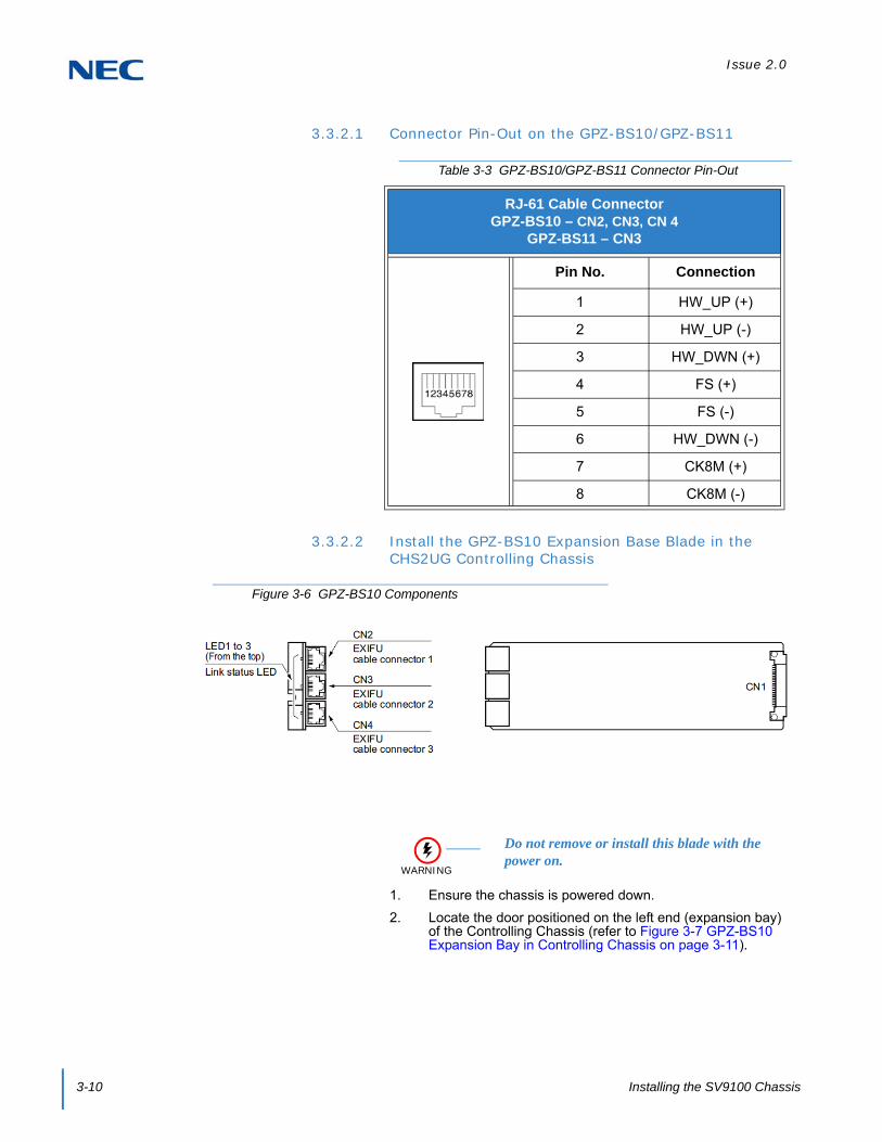
Issue 2.0
3-10 Installing the SV9100 Chassis
3.3.2.1 Connector Pin-Out on the GPZ-BS10/GPZ-BS11
3.3.2.2 Install the GPZ-BS10 Expansion Base Blade in the CHS2UG Controlling Chassis
1. Ensure the chassis is powered down.
2. Locate the door positioned on the left end (expansion bay) of the Controlling Chassis (refer to Figure 3-7 GPZ-BS10 Expansion Bay in Controlling Chassis on page 3-11).
Table 3-3 GPZ-BS10/GPZ-BS11 Connector Pin-Out
RJ-61 Cable ConnectorGPZ-BS10 – CN2, CN3, CN 4
GPZ-BS11 – CN3
Pin No. Connection
1 HW_UP (+)
2 HW_UP (-)
3 HW_DWN (+)
4 FS (+)
5 FS (-)
6 HW_DWN (-)
7 CK8M (+)
8 CK8M (-)
Figure 3-6 GPZ-BS10 Components
WARNING
Do not remove or install this blade with the power on.

Issue 2.0
SV9100 System Hardware Manual 3-11
3. From the left side of the chassis, pull cover outward to expose the expansion bay.
4. Pull the cover toward you to remove.
Cover must be removed prior to installation of GPZ-BS10 blade.
Figure 3-7 GPZ-BS10 Expansion Bay in Controlling Chassis
Expansion Bay
Figure 3-8 Open Base Chassis Cover

Issue 2.0
3-12 Installing the SV9100 Chassis
5. Align the GPZ-BS10 blade with the guides located in the expansion bay.
6. Slide the GPZ-BS10 blade into the chassis until resistance (back plane) is felt.
7. Gently push until the blade seats and install the supplied retaining screw.
8. Align the door tabs with hinges and reattach the cover (refer to Figure 3-11 GPZ-BS10 Blade Installed on page 3-13).
Figure 3-9 GPZ-BS10 Blade Guides
Figure 3-10 Installing GPZ-BS10 Blade in Expansion Bay

Issue 2.0
SV9100 System Hardware Manual 3-13
9. Close the GPZ-BS10 cover.
3.3.2.3 Install the GPZ-BS11 Expansion Blade in the CHS2UG Expansion Chassis
Figure 3-11 GPZ-BS10 Blade Installed
Figure 3-12 GPZ-BS10 Installed (Cover Closed)
Figure 3-13 GPZ-BS11 Components
CAUTION
For the Expansion Chassis to function, the GPZ-BS10 blade must be installed in Controlling Chassis.

Issue 2.0
3-14 Installing the SV9100 Chassis
1. Ensure the chassis is powered down.
2. Locate the door positioned on the left end (expansion bay) of the Expansion Chassis.
3. From the left side of the chassis, pull cover outward to expose the expansion bay (refer to Figure 3-15 Open Expansion Chassis Cover on page 3-14).
4. Pull the cover toward you to remove.
Cover must be removed to install GPZ-BS11 blade.
WARNING
Do not remove or install this blade with the power on.
Figure 3-14 GPZ-BS11 Expansion Bay in Expansion Chassis
Expansion Bay
Figure 3-15 Open Expansion Chassis Cover

Issue 2.0
SV9100 System Hardware Manual 3-15
5. Align the GPZ-BS11 blade with the guides located within the expansion bay.
6. Slide the GPZ-BS11 blade into the chassis until resistance (back plane) is felt.
7. Gently push until the blade seats and install the supplied retaining screw.
Figure 3-16 GPZ-BS11 Blade Guides
Figure 3-17 Installing GPZ-BS11 Blade in Expansion Chassis

Issue 2.0
3-16 Installing the SV9100 Chassis
8. Align the door tabs with hinges and reattach the cover.
9. Close the GPZ-BS11 blade cover.
Figure 3-18 GPZ-BS11 Blade Installed
Figure 3-19 GPZ-BS11 Installed (Cover Closed)

Issue 2.0
SV9100 System Hardware Manual 3-17
3.3.2.4 Connect the Controlling and Expansion Chassis
1. Ensure Controlling and Expansion chassis are powered down.
2. Using the NEC provided CAT5 straight-through cable(s), attach one end to each Expansion Chassis CN2 connector on the GPZ-BS11 blade (see Figure 3-21 System Expansion Cabling on page 3-18). Attach the opposite end to the CN2, CN3 or CN4 connector on the GPZ-BS10 of the Controlling Chassis.
CAUTION
Installment of the GPZ-BS10 blade and GPZ-BS11 blade(s) must be completed prior to installation of the provided (CAT 5) expansion cabling
Figure 3-20 19” Expansion Chassis Interface Units
Expansion Chassis Interface Unit for the Controlling Chassis
GPZ-BS10
Expansion Chassis Interface Unit for the Expansion Chassis
GPZ-BS11

Issue 2.0
3-18 Installing the SV9100 Chassis
3. Repeat for additional Expansion Chassis.
Figure 3-21 System Expansion Cabling
Install in Controlling Chassis
Install in Expansion Chassis
Install in Expansion Chassis
Install in Expansion Chassis

Issue 2.0
SV9100 System Hardware Manual 3-19
3.3.3 Install Grounding on 19” Chassis
From the factory, the SG, ETH and PBXG grounds are located inside the chassis and are connected to the FG ground (frame ground) on the back of the chassis.
Each chassis (CHS2UG) in the system must be grounded separately using the procedure listed below.
1. Ensure each Chassis is powered down and unplugged.
2. Ground each chassis by connecting a 14 AWG wire from the FG lug on the back side of the chassis to an electrical service ground (Connect to grounding conductor (Less than 10 ohms)).
3.3.4 Install Grounding on Multiple 19” Chassis (Optional)
From the factory, the SG, ETH and PBXG grounds are located inside the chassis and are connected to the FG ground (frame ground) on the back of the chassis.
Each chassis (CHS2UG) in the system must be grounded separately using the procedure listed below.
1. Ensure all Controlling and Expansion Chassis are powered down and unplugged.
2. Ground each chassis by connecting a 14 AWG wire from the FG lug on the back side of the chassis to an electrical service ground (Connect to grounding conductor (Less than 10 ohms)). Refer to Figure 3-23 19” Chassis Grounding Lug (Multiple-Chassis) on page 3-20 for grounding illustration.
Figure 3-22 Chassis Grounding Lug
FG Lug
CHS2UG

Issue 2.0
3-20 Installing the SV9100 Chassis
3.3.5 Install AC Power Cords on 19” Chassis
1. Locate the supplied AC power cord and attach to the AC Inlet located on the back of the Controlling Chassis.
Figure 3-23 19” Chassis Grounding Lug (Multiple-Chassis)
FG Lugs
Electrical Service Ground
Figure 3-24 Install the AC Power Cord
AC InletCHS2UG

Issue 2.0
SV9100 System Hardware Manual 3-21
3.3.6 Install AC Power Cords on Multiple 19” Chassis (Optional)
To install the AC power cords, locate the supplied AC power cords and attach to the AC Inlets located on the back of the Controlling and Expansion Chassis.
3.3.7 Install Additional Blades 19” Chassis
Refer to Chapter 4, 2.1 Installation and Safety Precautions on page 4-4.
3.3.8 Apply Power to the 19” Chassis
Refer to Chapter 4, 2.6 Powering Up the SV9100 System on page 4-9.
Figure 3-25 Install 19” AC Power Cords (Multiple-Chassis)
AC Power Cords to AC Inlets

Issue 2.0
3-22 Installing the SV9100 Chassis
3.4 Installing the 9.5” Gateway (CHS2UG GW) and Base (CHS2UG B) Chassis
The CHS2UG GW and the CHS2UG B chassis have three universal blade slots for station, trunk and optional blades.
Before proceeding with installation of chassis, ensure site preparation is completed. The Gateway (CHS2UG GW) chassis can be:
Wall-mounted – refer to 4.2 Wall Mounting the 9.5” Gateway (CHS2UG GW) and Base (CHS2UG B) Chassis on page 3-46.
Stand-mounted – refer to 6.2 Stand Mounting the 9.5” CHS2UG B Chassis on page 3-78.
The Base (CHS2UG B) chassis can be:
Wall-mounted – refer to 4.2 Wall Mounting the 9.5” Gateway (CHS2UG GW) and Base (CHS2UG B) Chassis on page 3-46.
Stand-mounted refer to 6.2 Stand Mounting the 9.5” CHS2UG B Chassis on page 3-78.
From the factory, the SG, ETH and PBXG grounds are located inside the chassis and are connected to the FG (frame ground) on the back of the chassis.
Figure 3-26 9.5” Chassis (Front View)
3 Universal Slots (Slot 1 for CPU)Power Switch
and LED

Issue 2.0
SV9100 System Hardware Manual 3-23
3.4.1 Install Grounding on 9.5” Gateway or Base Chassis
1. Ensure the 9.5” chassis (CHS2UG GW or CHS2UG B) is powered off and the AC power cord is unplugged.
2. Ground the chassis by connecting a 14 AWG wire from the FG lug on the back side of the chassis to an electrical service ground (Connect to grounding conductor (Less than 10 ohms)). Refer to Figure 3-27 9.5” Chassis (Rear View).
3.4.2 Install AC Power Cord 9.5” Gateway or Base Chassis
Locate the supplied AC power cord and attach to the AC Inlet located on the back of the chassis [refer to Figure 3-27 9.5” Chassis (Rear View)].
3.4.3 Install Additional Blades 9.5” Gateway or Base Chassis
Refer to Chapter 4, 2.1 Installation and Safety Precautions on page 4-4.
3.4.4 Apply Power to the 9.5” Gateway or Base Chassis
Refer to Chapter 4, 2.6 Powering Up the SV9100 System on page 4-9.
Figure 3-27 9.5” Chassis (Rear View)
Ground AC InletFor External Battery (12V Connection)
CHS2UG BChassis

Issue 2.0
3-24 Installing the SV9100 Chassis
3.5 Installing the 9.5” Base (CHS2UG B) and Expansion (CHS2UG E) Chassis
The CHS2UG B and CHS2UG E chassis combined have six universal blade slots for legacy line/trunk blade (Single Line Telephone Interface, Digital multiline terminal Interface, Central Office Trunk, ISDN PRI Interface, etc.), In-skin Application Blades (In-skin UMS, In-Skin Router, etc.). It also houses the BUS Interface Blade and Power Supply Unit (PSU).
When the GCD-CP10 blade is installed in slot 1 of the 9.5” Base Chassis, it is called the controlling chassis. Additional chassis, (9.5” Expansion Chassis) can be installed to increase the capacity of the system to meet the customer’s business needs.
Before proceeding with installation of chassis, ensure site preparation is completed. The combined chassis can be:
Wall-mounted – refer to 4.2.1.1 Wall Mounting the 9.5” Base (CHS2UG B) and Expansion (CHS2UG E) Chassis on page 3-54.
Rack-mounted – refer to 7.2 Rack Mounting the 9.5” Base (CHS2UG B) and Expansion (CHS2UG E) Chassis on page 3-84.
Figure 3-28 9.5”Base and Expansion (Combined) Chassis
Base ChassisCHS2UG B
Expansion ChassisCHS2UG EGPZ-BS10 or
GPZ-BS11 Slot
Power Switch and LED
3 Universal Slots (Slot 1 for CPU)
3 Universal Slots

Issue 2.0
SV9100 System Hardware Manual 3-25
The 9.5" Base chassis provides up to 16 trunk ports or 32 extension ports. An Expansion Chassis can be installed to the right of the Controlling or Base Chassis providing an additional 48 ports (40 trunk/ 80 stations maximum) and can include any combination of stations and trunks below this number. With a maximum of four Base and four Expansion chassis the system will provide up to 184 trunks and 368 extensions. With IP connections, a maximum of 400 trunk ports (maximum of 256 talk paths supported depending on the IPLE daughter board installed) and 896 station ports is possible.
A license is required to support the expanded ports.
3.5.1 Connecting the 9.5” Base and Expansion Chassis
1. Ensure the 9.5” chassis (Base and Expansion) is powered off and the AC power cord is unplugged.
2. Remove the screw, then the Backboard Cover located on the right side of the Base chassis (refer to Figure 3-29 Removing Backboard Cover).
Figure 3-29 Removing Backboard Cover

Issue 2.0
3-26 Installing the SV9100 Chassis
3. Match the Joint Bracket with screw holes A, B, C and D on the side of the Base Chassis (refer to Figure 3-30 Installing the Expansion Bracket), and install with four M4 x 14 screws.
4. From the Expansion Chassis, loosen and remove screws d and e from the top cover (refer to Figure 3-31 Remove Expansion Chassis Cover). Slide cover toward rear of chassis and lift to remove.
Figure 3-30 Installing the Expansion Bracket
Figure 3-31 Remove Expansion Chassis Cover
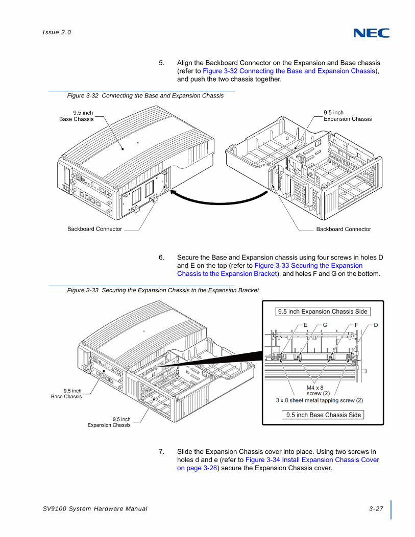
Issue 2.0
SV9100 System Hardware Manual 3-27
5. Align the Backboard Connector on the Expansion and Base chassis (refer to Figure 3-32 Connecting the Base and Expansion Chassis), and push the two chassis together.
6. Secure the Base and Expansion chassis using four screws in holes D and E on the top (refer to Figure 3-33 Securing the Expansion Chassis to the Expansion Bracket), and holes F and G on the bottom.
7. Slide the Expansion Chassis cover into place. Using two screws in holes d and e (refer to Figure 3-34 Install Expansion Chassis Cover on page 3-28) secure the Expansion Chassis cover.
Figure 3-32 Connecting the Base and Expansion Chassis
Figure 3-33 Securing the Expansion Chassis to the Expansion Bracket

Issue 2.0
3-28 Installing the SV9100 Chassis
8. Using two screws, secure the Base and Expansion chassis together with the metal reinforcement bracket provided.
Figure 3-34 Install Expansion Chassis Cover
IMPORTANT
Be sure to mount the Reinforcement Bracket with the 9.5 inch Base and Expansion Chassis in the vertical position.
NOTE
The Reinforcement Bracket and two screws are provided with the 9.5 inch Chassis.
Figure 3-35 Installing Reinforcement Bracket

Issue 2.0
SV9100 System Hardware Manual 3-29
3.5.2 Installing Expansion Blades in the 9.5” Base and Expansion Chassis (Optional)
When adding additional chassis to the system to expand the capacity, a GPZ-BS10 must be installed in the Controlling Chassis and a GPZ-BS11 must be installed in all Expansion Chassis. This connection is required with any multiple-chassis setup.
The GPZ-BS10 connects the Controlling Chassis to the Expansion Chassis by connecting to a GPZ-BS11, which is installed on each Expansion Chassis. These Expansion Interface Units allow the CPU to transmit/receive data as required to the additional chassis.
The GPZ-BS10 is installed in the Expansion bay of the Controlling Chassis which is equipped with a CPU blade. The GPZ-BS11 is installed in the Expansion bay of the Expansion Chassis, which does not have a CPU.
The Expansion cable connects the Controlling Chassis and its GPZ-BS10 interface to the second, third, and fourth GPZ-BS11 interface.
Use only the CAT 5 cables provided by NEC to make the connections between the Controlling and Expansion Chassis.
The GPZ-BS10 provides:
Communication Processor Interface for data handling through Communication Channel (24 slots maximum)
64 Channels for Telephony Resource (e.g., DTMF Tone Receiver, Call Progress Tone Detector, MFC Tone Receiver, Caller ID Receiver, Caller ID Signal Sender)
DSP Resource Management

Issue 2.0
3-30 Installing the SV9100 Chassis
3.5.2.1 Connector Pin-Out on the GPZ-BS10/GPZ-BS11
3.5.2.2 Install the GPZ-BS10 Expansion Base Blade in the CHS2UG B Controlling Chassis
1. Ensure the chassis is powered down.
2. Locate the door positioned on the left end (expansion bay) of the Controlling Chassis.
3. From the right side of the door, pinch the Door Clip and pull the cover outward to expose the expansion bay (refer to Figure 3-37 CHS2UG B Expansion Bay on page 3-31).
Table 3-4 GPZ-BS10/GPZ-BS11 Connector Pin-Out
RJ-61 Cable ConnectorGPZ-BS10 – CN2, CN3, CN 4
GPZ-BS11 – CN3
Pin No. Connection
1 HW_UP (+)
2 HW_UP (-)
3 HW_DWN (+)
4 FS (+)
5 FS (-)
6 HW_DWN (-)
7 CK8M (+)
8 CK8M (-)
Figure 3-36 GPZ-BS10 Components
WARNING
Do not remove or install this blade with the power on.

Issue 2.0
SV9100 System Hardware Manual 3-31
4. Pull the cover toward you to remove.
5. Remove knockout in center of cover.
6. Align the GPZ-BS10 blade with the guides located in the expansion bay.
7. Slide the GPZ-BS10 blade into the chassis until resistance (back plane) is felt (refer to Figure 3-38 Installing the GPZ-BS10 on page 3-32).
Figure 3-37 CHS2UG B Expansion Bay
IMPORTANT
Cover must be removed prior to installation of GPZ-BS10 blade.
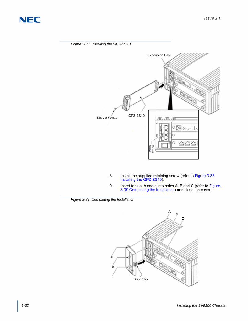
Issue 2.0
3-32 Installing the SV9100 Chassis
8. Install the supplied retaining screw (refer to Figure 3-38 Installing the GPZ-BS10).
9. Insert tabs a, b and c into holes A, B and C (refer to Figure 3-39 Completing the Installation) and close the cover.
Figure 3-38 Installing the GPZ-BS10
Figure 3-39 Completing the Installation

Issue 2.0
SV9100 System Hardware Manual 3-33
3.5.2.3 Install the GPZ-BS11 Expansion Blade in the CHS2UG B Expansion Chassis
1. Ensure the chassis is powered down.
2. Locate the door positioned on the left end (expansion bay) of the Expansion Chassis.
3. From the right side of the door, pinch the Door Clip and pull the cover outward to expose the expansion bay.
4. Pull the cover toward you to remove.
5. Remove knockout in center of cover.
Figure 3-40 GPZ-BS11 Components
CAUTION
For the Expansion Chassis to function, the GPZ-BS10 blade must be installed in Controlling Chassis.
WARNING
Do not remove or install this blade with the power on.
Figure 3-41 CHS2UG B Expansion Bay
IMPORTANT
Cover must be removed prior to installation of GPZ-BS11 blade.

Issue 2.0
3-34 Installing the SV9100 Chassis
6. Align the GPZ-BS11 blade with the guides located in the expansion bay.
7. Slide the GPZ-BS11 blade into the chassis until resistance (back plane) is felt.
8. Install the supplied retaining screw.
9. Insert tabs a, b and c into holes A, B and C (refer to Figure 3-43 Completing the Installation) and close the cover.
Figure 3-42 Installing the GPZ-BS11
Figure 3-43 Completing the Installation
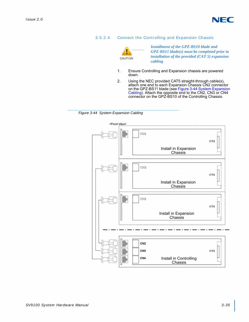
Issue 2.0
SV9100 System Hardware Manual 3-35
3.5.2.4 Connect the Controlling and Expansion Chassis
1. Ensure Controlling and Expansion chassis are powered down.
2. Using the NEC provided CAT5 straight-through cable(s), attach one end to each Expansion Chassis CN2 connector on the GPZ-BS11 blade (see Figure 3-44 System Expansion Cabling). Attach the opposite end to the CN2, CN3 or CN4 connector on the GPZ-BS10 of the Controlling Chassis.
CAUTION
Installment of the GPZ-BS10 blade and GPZ-BS11 blade(s) must be completed prior to installation of the provided (CAT 5) expansion cabling
Figure 3-44 System Expansion Cabling
Install in Controlling Chassis
Install in Expansion Chassis
Install in Expansion Chassis
Install in Expansion Chassis

Issue 2.0
3-36 Installing the SV9100 Chassis
EXAMPLE:
0 CHS2UG (19” Chassis) & 4 CHS2UG B/CHS2UG E (9.5” Base Chassis/9.5” Expansion Chassis)
1 CHS2UG (19” Chassis) & 3 CHS2UG B/CHS2UG E (9.5” Base Chassis/9.5” Expansion Chassis)
2 CHS2UG (19” Chassis) & 2 CHS2UG B/CHS2UG E (9.5” Base Chassis/9.5” Expansion Chassis)
3 CHS2UG (19” Chassis) & 1 CHS2UG B/CHS2UG E (9.5” Base Chassis/9.5” Expansion Chassis)
4 CHS2UG (19” Chassis) & 0 CHS2UG B/CHS2UG E (9.5” Base Chassis/9.5” Expansion Chassis)
3. Repeat for additional Expansion Chassis.
3.5.3 Installing Grounding on 9.5” Base and Expansion Chassis
1. Ensure the 9.5” chassis is powered off and the AC power cord is unplugged.
2. Ground the chassis [refer to Figure 3-45 9.5” Chassis (Rear View)] by connecting a 14 AWG wire from the FG lug on the back side of the chassis to an electrical service ground (Connect to grounding conductor (Less than 10 ohms)).
The CHS2UG E (9.5” expansion chassis) does not have an FG lug.
Figure 3-45 9.5” Chassis (Rear View)
Ground AC InletFor External Battery (12V Connection)
CHS2UG

Issue 2.0
SV9100 System Hardware Manual 3-37
3.5.4 Install Grounding on Multiple 9.5” Base and Expansion Chassis
From the factory, the SG, ETH and PBXG grounds are located inside the chassis and are connected to the FG ground (frame ground) on the back of the chassis.
Each chassis (CHS2UG B) in the system must be grounded separately using the procedure listed below.
The CHS2UG E (9.5” expansion chassis) does not have an FG lug.
1. Ensure all Controlling and Expansion Chassis are powered down and unplugged.
2. Ground each chassis [refer to Figure 3-45 9.5” Chassis (Rear View) on page 3-36] by connecting a 14 AWG wire from the FG lug on the back side of the chassis to an electrical service ground (Connect to grounding conductor (Less than 10 ohms)).
3.5.5 Install AC Power Cord on 9.5” Base and Expansion Chassis
Locate the supplied AC power cord and attach to the AC Inlet located on the back of the chassis [refer to Figure 3-45 9.5” Chassis (Rear View) on page 3-36].
The CHS2UG E (9.5” expansion chassis) does not have an AC Inlet.
3.5.6 Install AC Power Cord on Multiple 9.5” Base and Expansion Chassis
Locate the supplied AC power cords and attach to the AC Inlets located on the back of the Controlling and Expansion Chassis.
The CHS2UG E (9.5” expansion chassis) does not have an AC Inlet.
3.5.7 Install Additional Blades in the 9.5” Base and Expansion Chassis
Refer to Chapter 4, 2.1 Installation and Safety Precautions on page 4-4.
3.5.8 Applying Power to the 9.5” Base and Expansion Chassis
Refer to Chapter 4, 2.6 Powering Up the SV9100 System on page 4-9.

Issue 2.0
3-38 Installing the SV9100 Chassis
SECTION 4 WALL MOUNTING THE CHASSIS
4.1 Wall Mounting the 19” (CHS2UG) Chassis
When wall mounting the chassis, ensure the wall can support the weight of the chassis (55 lbs per system chassis – including blades, cords, power supply, etc.). The chassis is secured to the wall with a wall mount bracket. Ensure that enough space is available to allow the installation of additional expansion chassis.
4.1.1 CHS2UG Chassis Wall Mount Installation
1. Use the template shown in Figure 3-46 Wall Mount Spacing Guide (19” Chassis) on page 3-39 for required spacing before drilling.
TIP
Plywood should first be installed on the wall where the chassis will be positioned. This allows secure anchoring of the screws which support the weight of the chassis.
Due to chassis weight, NEC recommends only a single CHS2UG chassis per wall mount.

Issue 2.0
SV9100 System Hardware Manual 3-39
2. Mark and drill the six holes required for a wall installation.
3. Align screw holes in wall mount brackets with drilled holes.
4. Using six screws, secure the two wall mount brackets to the wall.
Figure 3-46 Wall Mount Spacing Guide (19” Chassis)

Issue 2.0
3-40 Installing the SV9100 Chassis
Figure 3-47 Install Wall Mount Brackets with Screws

Issue 2.0
SV9100 System Hardware Manual 3-41
5. Using four screws, secure the metal fittings on the Left and Right sides of the 19” chassis.
Figure 3-48 Securing Metal Fittings to Chassis with Screws

Issue 2.0
3-42 Installing the SV9100 Chassis
6. Align the metal fitting with the upper wall mount bracket. The lower metal fitting rests against the lower wall mount bracket. Secure the metal fitting and upper wall mount bracket with a single screw.
Figure 3-49 Secure Metal Fitting to Upper Wall Mount Bracket with a Screw

Issue 2.0
SV9100 System Hardware Manual 3-43
7. Using two screws, secure the metal fitting to the lower wall mount bracket. Refer to Figure 3-50 Secure Metal Fitting to Lower Wall Mount Bracket with Screws for screw location.
8. Attach the supplied cable support bracket to either end of the lower wall mount bracket with a single screw (refer to Figure 3-51 Attach Cable Support Bracket to Lower Wall Mount Bracket on page 3-44).
Figure 3-50 Secure Metal Fitting to Lower Wall Mount Bracket with Screws

Issue 2.0
3-44 Installing the SV9100 Chassis
Figure 3-51 Attach Cable Support Bracket to Lower Wall Mount Bracket

Issue 2.0
SV9100 System Hardware Manual 3-45
9. The cable support bracket can be installed any of the four corners of the 19” chassis (refer to Figure 3-52 Attachment Locations of Cable Support Bracket on page 3-45).
10. Connect the ground wire to all chassis. Refer to 3.3.3 Install Grounding on 19” Chassis on page 3-19 for complete details on grounding the system.
11. Refer to 3.3.5 Install AC Power Cords on 19” Chassis on page 3-20 to continue installation of the chassis or, Chapter 6 paragraph 2.1 Installation and Safety Precautions on page 4-4 for installation of blades.
Figure 3-52 Attachment Locations of Cable Support Bracket
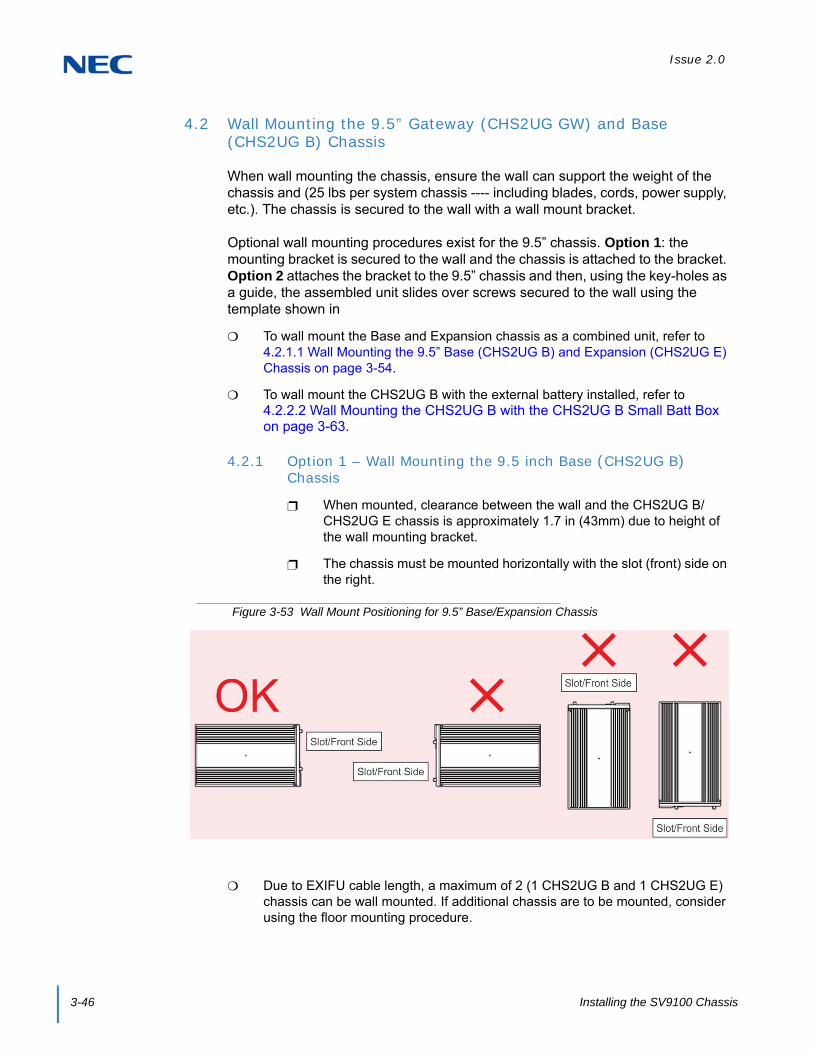
Issue 2.0
3-46 Installing the SV9100 Chassis
4.2 Wall Mounting the 9.5” Gateway (CHS2UG GW) and Base (CHS2UG B) Chassis
When wall mounting the chassis, ensure the wall can support the weight of the chassis and (25 lbs per system chassis ---- including blades, cords, power supply, etc.). The chassis is secured to the wall with a wall mount bracket.
Optional wall mounting procedures exist for the 9.5” chassis. Option 1: the mounting bracket is secured to the wall and the chassis is attached to the bracket. Option 2 attaches the bracket to the 9.5” chassis and then, using the key-holes as a guide, the assembled unit slides over screws secured to the wall using the template shown in
To wall mount the Base and Expansion chassis as a combined unit, refer to 4.2.1.1 Wall Mounting the 9.5” Base (CHS2UG B) and Expansion (CHS2UG E) Chassis on page 3-54.
To wall mount the CHS2UG B with the external battery installed, refer to 4.2.2.2 Wall Mounting the CHS2UG B with the CHS2UG B Small Batt Box on page 3-63.
4.2.1 Option 1 – Wall Mounting the 9.5 inch Base (CHS2UG B) Chassis
When mounted, clearance between the wall and the CHS2UG B/CHS2UG E chassis is approximately 1.7 in (43mm) due to height of the wall mounting bracket.
The chassis must be mounted horizontally with the slot (front) side on the right.
Due to EXIFU cable length, a maximum of 2 (1 CHS2UG B and 1 CHS2UG E) chassis can be wall mounted. If additional chassis are to be mounted, consider using the floor mounting procedure.
Figure 3-53 Wall Mount Positioning for 9.5” Base/Expansion Chassis

Issue 2.0
SV9100 System Hardware Manual 3-47
When mounting the Expansion chassis, leave a space of approximately 0.4 in (10mm) between the two for the EXIFU cable.
1. Use the template shown in Figure 3-54 Wall Mount Spacing Guide (9.5” Chassis) for required spacing before drilling.
2. Mark and drill four holes marked A, B, C and D.
3. Mount Anchor bolts (locally procured), in holes A and B drilled in step 2.
Because the bracket (upper) will be hooked onto the head of the anchor bolts, allow the head to protrude approximately 0.14 to 15 in (3.5 to 4.0mm) from the wall (refer to (Figure 3-55 Anchor Bolt from Wall (9.5” Chassis) on page 3-48).
Figure 3-54 Wall Mount Spacing Guide (9.5” Chassis)
TIP
Plywood should first be installed on the wall where the chassis will be positioned. This allows secure anchoring of the screws, which support the weight of the chassis.

Issue 2.0
3-48 Installing the SV9100 Chassis
4. Align the upper bracket holes a and b with the heads of anchor bolts A and B mounted on the wall and slide downward (refer to Figure 3-56 Align Bracket on Wall (9.5” Chassis)).
5. Install anchor bolts in holes C and D (refer to Figure 3-54 Wall Mount Spacing Guide (9.5” Chassis) on page 3-47). Tighten all four anchor bolts.
Figure 3-55 Anchor Bolt from Wall (9.5” Chassis)
Figure 3-56 Align Bracket on Wall (9.5” Chassis)

Issue 2.0
SV9100 System Hardware Manual 3-49
6. Align holes E and F on the MV bracket (upper) with holes on the 9.5 inch Basic Chassis (CHS2UG B). Install 2 M4 x 14 screws.
2 M4 x 14 screws are provided with the CHS2UG - MOVABLE WALL MOUNT KIT.
7. Install the screws in the holes closest to the wall side of the bracket (refer to Figure 3-57 Install Upper Bracket (9.5” Chassis)).
8. If the CHS2UG B SMALL BATT BOX is mounted on the 9.5 inch chassis, install the screws in the holes on the left edge of the bracket (refer to Figure 3-58 Optional Small Battery Box (9.5” Chassis) on page 3-50).
Figure 3-57 Install Upper Bracket (9.5” Chassis)
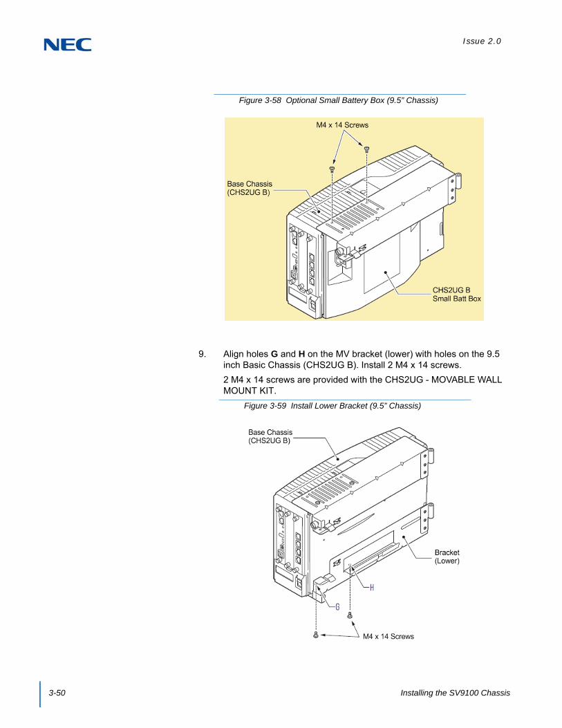
Issue 2.0
3-50 Installing the SV9100 Chassis
9. Align holes G and H on the MV bracket (lower) with holes on the 9.5 inch Basic Chassis (CHS2UG B). Install 2 M4 x 14 screws.
2 M4 x 14 screws are provided with the CHS2UG - MOVABLE WALL MOUNT KIT.
Figure 3-58 Optional Small Battery Box (9.5” Chassis)
Figure 3-59 Install Lower Bracket (9.5” Chassis)
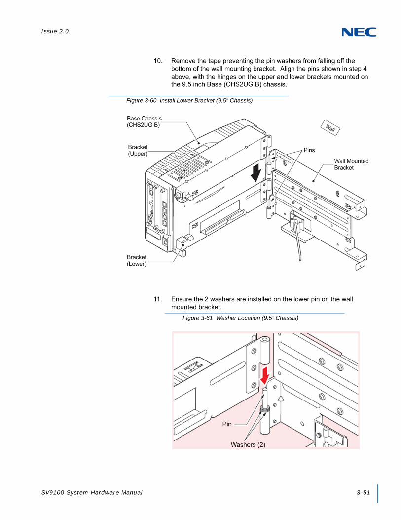
Issue 2.0
SV9100 System Hardware Manual 3-51
10. Remove the tape preventing the pin washers from falling off the bottom of the wall mounting bracket. Align the pins shown in step 4 above, with the hinges on the upper and lower brackets mounted on the 9.5 inch Base (CHS2UG B) chassis.
11. Ensure the 2 washers are installed on the lower pin on the wall mounted bracket.
Figure 3-60 Install Lower Bracket (9.5” Chassis)
Figure 3-61 Washer Location (9.5” Chassis)

Issue 2.0
3-52 Installing the SV9100 Chassis
12. Attach the shaft from the mounted wall bracket to the lower bracket and secure using the supplied retaining washer.
13. Using the 2 M3 x 6 spring washer screws supplied, install the stopper between the chassis and the wall mounted bracket.
Figure 3-62 Install the Shaft (9.5” Chassis)
Figure 3-63 Install the Stopper (9.5” Chassis)

Issue 2.0
SV9100 System Hardware Manual 3-53
14. Lift the shaft and close the 9.5 inch chassis. To secure the chassis to the wall, tighten the knurled screws located on the upper and lower brackets.
15. Connect grounding wire to chassis. Refer to Chapter 4 paragraph 3.5 Installing the 9.5” Base (CHS2UG B) and Expansion (CHS2UG E) Chassis on page 3-24 for complete details on grounding the system.
16. Refer to 3.5.5 Install AC Power Cord on 9.5” Base and Expansion Chassis on page 3-37 for installation of the power cord or, Chapter 6 paragraph 2.1 Installation and Safety Precautions on page 4-4 for installation of blades.
Figure 3-64 Chassis Installed (9.5” Chassis)

Issue 2.0
3-54 Installing the SV9100 Chassis
4.2.1.1 Wall Mounting the 9.5” Base (CHS2UG B) and Expansion (CHS2UG E) Chassis
1. Use the template shown in Figure 3-65 Wall Mount Spacing Guide (Base and Expansion Chassis) for required spacing before drilling.
2. Mark and drill four holes marked A, B, C and D.
3. Mount Anchor bolts (locally procured), in holes A and B drilled in step 2.
Because the bracket (upper) will be hooked onto the head of the anchor bolts, allow the head to protrude approximately 0.14 to 15 in (3.5 to 4.0mm) from the wall (refer to (Figure 3-66 Anchor Bolt from Wall (9.5” Chassis) on page 3-55).
Figure 3-65 Wall Mount Spacing Guide (Base and Expansion Chassis)
TIP
Plywood should first be installed on the wall where the chassis will be positioned. This allows secure anchoring of the screws, which support the weight of the chassis.

Issue 2.0
SV9100 System Hardware Manual 3-55
4. Remove the M4 x 8 screws from the wall mount bracket.
Use the screw holes marked with the number 2 on the upper and lower brackets.
Figure 3-66 Anchor Bolt from Wall (9.5” Chassis)
Figure 3-67 Remove Support Bracket (Base and Expansion Chassis)

Issue 2.0
3-56 Installing the SV9100 Chassis
5. Turn the support 90° and install the M4 x 8 screws previously removed.
6. Attach the MV bracket (upper and lower) to the 9.5 inch Base and Expansion chassis. Refer to section 4.2.1 Option 1 – Wall Mounting the 9.5 inch Base (CHS2UG B) Chassis steps 4 through 14 for bracket installation.
Or
Figure 3-68 Install Support Bracket (Base and Expansion Chassis)

Issue 2.0
SV9100 System Hardware Manual 3-57
7. Connect grounding wire to chassis. Refer to Chapter 4 paragraph 3.5 Installing the 9.5” Base (CHS2UG B) and Expansion (CHS2UG E) Chassis on page 3-24 for complete details on grounding the system.
8. Refer to 3.5.5 Install AC Power Cord on 9.5” Base and Expansion Chassis on page 3-37 for installation of the power cord or, Chapter 6 paragraph 2.1 Installation and Safety Precautions on page 4-4 for installation of blades.
Figure 3-69 Chassis Installed (Base and Expansion Chassis)

Issue 2.0
3-58 Installing the SV9100 Chassis
4.2.2 Option 2 – Wall Mounting the 9.5 inch Base (CHS2UG B) Chassis
1. Use the template shown in Figure 3-54 Wall Mount Spacing Guide (9.5” Chassis) for required spacing before drilling.
2. Mark and drill four holes marked A, B, C and D.
3. Mount Anchor bolts (locally procured), in holes A and B drilled in step 2.
Because the bracket (upper) will be hooked onto the head of the anchor bolts, allow the head to protrude approximately 0.14 to 15 in (3.5 to 4.0mm) from the wall (refer to (Figure 3-71 Anchor Bolt from Wall (9.5” Chassis) on page 3-59).
Figure 3-70 Wall Mount Spacing Guide (9.5” Chassis)
TIP
Plywood should first be installed on the wall where the chassis will be positioned. This allows secure anchoring of the screws, which support the weight of the chassis.

Issue 2.0
SV9100 System Hardware Manual 3-59
4.2.2.1 Wall Mounting the CHS2UG B without the CHS2UG B Small Batt Box
1. Align the bracket halves (refer to Figure 3-72 Wall Mounting Brackets (Option 2)).
Figure 3-71 Anchor Bolt from Wall (9.5” Chassis)
Figure 3-72 Wall Mounting Brackets (Option 2)

Issue 2.0
3-60 Installing the SV9100 Chassis
2. Align holes E and F on the MV bracket (upper) with holes on the 9.5 inch Basic Chassis (CHS2UG B). Install 2 M4 x 14 screws.
M4 x 14 screws are provided with the WALL MOUNT BRACKET.
3. Align holes G and H on the MV bracket (lower) with holes on the 9.5 inch Basic Chassis (CHS2UG B). Install 2 M4 x 14 screws.
M4 x 14 screws are provided with the WALL MOUNT BRACKET.
Figure 3-73 Install Upper Bracket (Option 2)
Figure 3-74 Install Lower Bracket (Option 2)

Issue 2.0
SV9100 System Hardware Manual 3-61
4. Align the upper and lower bracket holes with the heads of anchor bolts mounted on the wall and slide downward (refer to Figure 3-75 Install Screws (Option 2)).
Or
5. Attach the MV bracket (upper and lower) to the 9.5 inch Base and Expansion chassis. Refer to section 4.2.2.1 Wall Mounting the CHS2UG B without the CHS2UG B Small Batt Box on page 3-59 steps 1 through 4 for bracket installation.
Figure 3-75 Install Screws (Option 2)

Issue 2.0
3-62 Installing the SV9100 Chassis
6. Connect grounding wire to chassis. Refer to Chapter 4 paragraph 3.5 Installing the 9.5” Base (CHS2UG B) and Expansion (CHS2UG E) Chassis on page 3-24 for complete details on grounding the system.
7. Refer to 3.5.5 Install AC Power Cord on 9.5” Base and Expansion Chassis on page 3-37 for installation of the power cord or, Chapter 6 paragraph 2.1 Installation and Safety Precautions on page 4-4 for installation of blades.
Figure 3-76 Wall Mount Spacing Guide – 9.5” Base and Expansion Chassis

Issue 2.0
SV9100 System Hardware Manual 3-63
4.2.2.2 Wall Mounting the CHS2UG B with the CHS2UG B Small Batt Box
To install the CHS2UG B SMALL BATT BOX refer to section 8.3 Installing the CHS2UG B SMALL BATT BOX on the 9.5” CHS2UG B Chassis on page 3-104
1. Align the bracket halves (refer to Figure 3-72 Wall Mounting Brackets (Option 2)).
2. Turn the brackets upside down and remove four screws (refer to Figure 3-78 Brackets (Small Batt Box) on page 3-64).
Figure 3-77 Wall Mounting (Small Batt Box)

Issue 2.0
3-64 Installing the SV9100 Chassis
Figure 3-78 Brackets (Small Batt Box)

Issue 2.0
SV9100 System Hardware Manual 3-65
3. Align the holes marked as R and F.
Figure 3-79 Reposition Brackets (Small Batt Box)

Issue 2.0
3-66 Installing the SV9100 Chassis
4. Install the four screws previously removed.
5. Align the brackets with the holes on the sides of the 9.5 inch Basic Chassis (CHS2UG B). Install 2 M4 x 14 screws.
Figure 3-80 Install Screws (Small Batt Box)
Figure 3-81 Wall Mount – Upper Side (Small Batt Box)
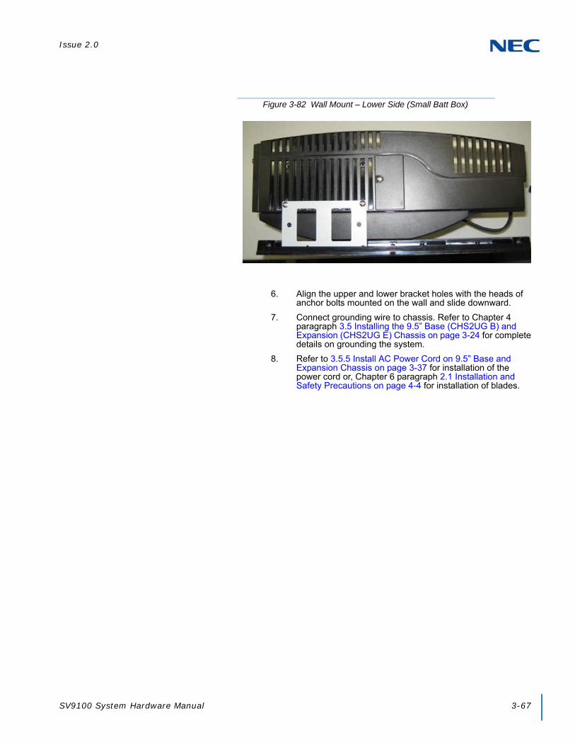
Issue 2.0
SV9100 System Hardware Manual 3-67
6. Align the upper and lower bracket holes with the heads of anchor bolts mounted on the wall and slide downward.
7. Connect grounding wire to chassis. Refer to Chapter 4 paragraph 3.5 Installing the 9.5” Base (CHS2UG B) and Expansion (CHS2UG E) Chassis on page 3-24 for complete details on grounding the system.
8. Refer to 3.5.5 Install AC Power Cord on 9.5” Base and Expansion Chassis on page 3-37 for installation of the power cord or, Chapter 6 paragraph 2.1 Installation and Safety Precautions on page 4-4 for installation of blades.
Figure 3-82 Wall Mount – Lower Side (Small Batt Box)

Issue 2.0
3-68 Installing the SV9100 Chassis
SECTION 5 FLOOR MOUNTING THE CHASSIS
5.1 Floor Mounting the 19” (CHS2UG) Chassis
The CHS2UG controlling and expansion chassis can be mounted on the floor using the CHS BASE UNIT and the CHS2UG JOINT BRACKET KIT.
5.1.1 CHS2UG Chassis Installation
1. Use the template shown in Figure 3-83 Floor Mount Spacing Guide for required spacing before drilling holes for 0.39” (10mm) anchor bolts (locally procured).
2. Mark and drill the four holes required to install the CHS BASE UNIT.
3. Using anchor bolts, secure the CHS BASE UNIT to the floor. Refer to Figure 3-84 Secure CHS BASE UNIT with Anchor Bolts for screw
Figure 3-83 Floor Mount Spacing Guide

Issue 2.0
SV9100 System Hardware Manual 3-69
location.
4. Install the five rubber feet to the bottom of the chassis.
5. Position the chassis on top of the CHS BASE UNIT.
Figure 3-84 Secure CHS BASE UNIT with Anchor Bolts
Figure 3-85 Install Rubber Feet (19” Chassis)

Issue 2.0
3-70 Installing the SV9100 Chassis
6. Secure the chassis to the CHS BASE UNIT using eight screws supplied with the CHS2UG JOINT BRACKET KIT.
7. Connect the ground wire to all chassis. Refer to 3.3.3 Install Grounding on 19” Chassis on page 3-19 for complete details on grounding the system.
8. Refer to 3.3.5 Install AC Power Cords on 19” Chassis on page 3-20 to continue installation of the chassis or, Chapter 6 paragraph 2.1 Installation and Safety Precautions on page 4-4 for installation of blades.
Figure 3-86 Install CHS2UG JOINT BRACKET KIT

Issue 2.0
SV9100 System Hardware Manual 3-71
5.1.2 Multiple CHS2UG Chassis Installation
Expansion chassis can be secured to the CHS BASE UNIT and require an additional CHS2UG JOINT BRACKET KIT per chassis.
1. Install the five rubber feet to the bottom of each chassis.
2. Using supplied screws in the CHS2UG JOINT BRACKET KIT, attach metal brackets to both ends of the 19” chassis and the CHS BASE UNIT. Refer to Figure 3-88 Install Metal Brackets with Screws.
Figure 3-87 Install Rubber Feet for Multiple Chassis
Figure 3-88 Install Metal Brackets with Screws
Metal Brackets

Issue 2.0
3-72 Installing the SV9100 Chassis
3. Connect the ground wire to all chassis. Refer to 3.3.3 Install Grounding on 19” Chassis on page 3-19 for complete details on grounding the system.
4. Refer to 3.3.5 Install AC Power Cords on 19” Chassis on page 3-20 to continue installation of the chassis or, Chapter 6 paragraph 2.1 Installation and Safety Precautions on page 4-4 for installation of blades.
SECTION 6 STAND MOUNTING THE CHASSIS
6.1 Stand Mounting the 19” (CHS2UG) Chassis
A single or multiple chassis can be stand mounted. Controlling and Expansion chassis can be stand mounted using the CHS2UG STAND KIT (K) and CHS2UG STAND KIT (EXT).
6.1.1 CHS2UG Chassis Installation
1. Using the supplied screws, assemble the CHS2UG STAND KIT (K) and CHS2UG STAND KIT (EXT) (refer to Figure 3-89 Assemble Stand Mount with Screws).
2. Secure the CHS2UG chassis to the assembled CHS2UG STAND KIT (K), see Figure 3-90 Secure CHS2UG Chassis to CHS2UG STAND KIT (K) with Screws on page 3-73.
Figure 3-89 Assemble Stand Mount with Screws
Expansion Plate

Issue 2.0
SV9100 System Hardware Manual 3-73
3. Using supplied screws, secure the CHS2UG STAND KIT (K) to the floor (refer to Figure 3-91 Secure Stand Mount to Floor with Screws on page 3-74).
Figure 3-90 Secure CHS2UG Chassis to CHS2UG STAND KIT (K) with Screws
WARNING
To prevent possible damage to the 19” chassis due to falling, NEC recommends screws be installed in the stand mount brackets as soon as possible.
Expansion Plate

Issue 2.0
3-74 Installing the SV9100 Chassis
4. Connect the ground wire to all chassis. Refer to 3.3.3 Install Grounding on 19” Chassis on page 3-19 for complete details on grounding the system.
5. Refer to 3.3.5 Install AC Power Cords on 19” Chassis on page 3-20 to continue installation of the chassis or, Chapter 6 paragraph 2.1 Installation and Safety Precautions on page 4-4 for installation of blades.
Figure 3-91 Secure Stand Mount to Floor with Screws

Issue 2.0
SV9100 System Hardware Manual 3-75
6.1.2 Multiple CHS2UG Chassis Installation
Expansion chassis (maximum of three) can be added to the CHS2UG STAND KIT (K) and require an additional CHS2UG STAND KIT (EXT) per chassis.
1. Install the five rubber feet to the bottom of each chassis.
2. Each additional chassis requires a CHS2UG STAND KIT (EXT) to be installed (refer to Figure 3-93 Install Additional CHS2UG STAND KIT (EXT) on page 3-76).
Figure 3-92 Attach Rubber Feet to CHS2UG Chassis

Issue 2.0
3-76 Installing the SV9100 Chassis
3. Metal brackets from the CHS2UG JOINT BRACKET KITs are required to secure the top end of the chassis with screws. See Figure 3-94 Install Additional Brackets from CHS2UG JOINT BRACKET KIT on page 3-77.
Figure 3-93 Install Additional CHS2UG STAND KIT (EXT)
Expansion Plates
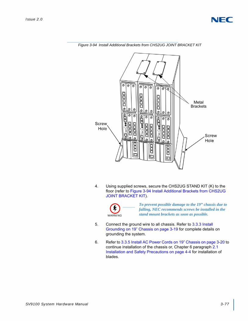
Issue 2.0
SV9100 System Hardware Manual 3-77
4. Using supplied screws, secure the CHS2UG STAND KIT (K) to the floor (refer to Figure 3-94 Install Additional Brackets from CHS2UG JOINT BRACKET KIT).
5. Connect the ground wire to all chassis. Refer to 3.3.3 Install Grounding on 19” Chassis on page 3-19 for complete details on grounding the system.
6. Refer to 3.3.5 Install AC Power Cords on 19” Chassis on page 3-20 to continue installation of the chassis or, Chapter 6 paragraph 2.1 Installation and Safety Precautions on page 4-4 for installation of blades.
Figure 3-94 Install Additional Brackets from CHS2UG JOINT BRACKET KIT
WARNING
To prevent possible damage to the 19” chassis due to falling, NEC recommends screws be installed in the stand mount brackets as soon as possible.
Metal Brackets

Issue 2.0
3-78 Installing the SV9100 Chassis
6.2 Stand Mounting the 9.5” CHS2UG B Chassis
The 9.5” chassis can be stand mounted using the brackets supplied. The following section describes this procedure.
1. Position the 9.5” Base Chassis so that the EXIFU slot is on top.
2. Align the Base unit with holes A, B, C and D on the lower side of the CHS2UG B chassis. Attach with the provided M4 x 14 screws.
WARNING
This bracket is not for use with a combined Base (CHS2UG B) and Expansion (CHS2UG E) chassis. A combined Base and Expansion chassis should only be rack or wall mounted.
NOTE
Using the chassis stand unit (stand/floor mounting), will increase the height of the chassis by 50 mm.
Figure 3-95 Attaching the Base Stand

Issue 2.0
SV9100 System Hardware Manual 3-79
3. Install tab slots D, E, F, G, H and I of either bracket (stand unit brackets can be mounted on the left or right side), on tabs d, e, f, g, h and i of the stand unit.
NOTE
When attaching the stand unit to the 9.5” Base chassis, ensure the shape of the stand unit aligns with the shape of the 9.5” chassis
Figure 3-96 9.5” Chassis with Base Stand Attached
Figure 3-97 Attaching the First Stand Unit Bracket

Issue 2.0
3-80 Installing the SV9100 Chassis
4. Install tab slots J, K, L, M, N and O of the remaining bracket on tabs j, k, l, m, n and o on the opposite side of the stand unit.
5. Align the support bracket with holes P and Q on the stand unit brackets and secure using the two M3 x 8 screws provided.
Figure 3-98 Attaching the Second Stand Unit Bracket
Figure 3-99 Installing the Support Bracket

Issue 2.0
SV9100 System Hardware Manual 3-81
6. Turn the 9.5 inch chassis over and place in the location to be installed.
7. Secure the 9.5” assembly to a flat surface with the four screws supplied.
8. Connect grounding wire to chassis. Refer to Chapter 4 paragraph 3.4 Installing the 9.5” Gateway (CHS2UG GW) and Base (CHS2UG B) Chassis on page 3-22 for complete details on grounding the system.
9. Refer to 3.3.5 Install AC Power Cords on 19” Chassis on page 3-20 for installation of the power cord or, Chapter 6 paragraph 2.1 Installation and Safety Precautions on page 4-4 for installation of blades.
Figure 3-100 Stand Mount 9.5” Chassis
WARNING
To prevent possible damage to the 19” chassis due to falling, NEC recommends screws be installed in the stand mount brackets as soon as possible.

Issue 2.0
3-82 Installing the SV9100 Chassis
SECTION 7 RACK MOUNTING THE CHASSIS
7.1 Rack Mounting the 19” (CHS2UG) Chassis
A single or multiple chassis can be rack mounted. Controlling and Expansion chassis can be racked mounted by stacking them horizontally.
1. The 19” chassis requires two rack mount brackets per chassis for mounting. Each 19" chassis requires its own set of rack mount bracket(s). Refer to Figure 3-101 CHS2UG Rack Mount Brackets.
2. Line up the Rack Mount Bracket(s) with the pre-drilled holes on each side of the 19” chassis.
3. Secure the brackets to the chassis using the supplied screws. Refer to Figure 3-102 Rack Mount Bracket Installed 19” CHS2UG on page 3-83 for the 19” chassis.
WARNING
Stacking additional chassis (without rack mount brackets) on top of one rack mounted chassis is not recommended.
Figure 3-101 CHS2UG Rack Mount Brackets
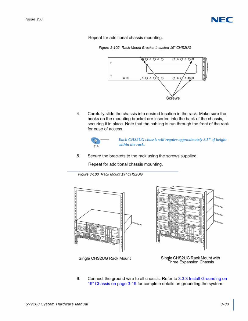
Issue 2.0
SV9100 System Hardware Manual 3-83
Repeat for additional chassis mounting.
4. Carefully slide the chassis into desired location in the rack. Make sure the hooks on the mounting bracket are inserted into the back of the chassis, securing it in place. Note that the cabling is run through the front of the rack for ease of access.
5. Secure the brackets to the rack using the screws supplied.
Repeat for additional chassis mounting.
6. Connect the ground wire to all chassis. Refer to 3.3.3 Install Grounding on 19” Chassis on page 3-19 for complete details on grounding the system.
Figure 3-102 Rack Mount Bracket Installed 19” CHS2UG
TIP
Each CHS2UG chassis will require approximately 3.5” of height within the rack.
Figure 3-103 Rack Mount 19” CHS2UG
Single CHS2UG Rack Mount Single CHS2UG Rack Mount with Three Expansion Chassis

Issue 2.0
3-84 Installing the SV9100 Chassis
7. Refer to 3.3.5 Install AC Power Cords on 19” Chassis on page 3-20 to continue installation of the chassis or, Chapter 6 paragraph 2.1 Installation and Safety Precautions on page 4-4 for installation of blades.
7.2 Rack Mounting the 9.5” Base (CHS2UG B) and Expansion (CHS2UG E) Chassis
To rack mount the combined Base (CHS2UG B) and Expansion (CHS2UG E) chassis, the IP5D-RACK MOUNT BAR SET is required.
1. Attach the metal rack mount brackets to each side of the chassis using the screws provided (refer to Figure 3-104 Attach Rack Mount Brackets to 9.5” Chassis).
WARNING
Controlling and Expansion chassis must be installed vertically for proper air circulation.
Figure 3-104 Attach Rack Mount Brackets to 9.5” Chassis

Issue 2.0
SV9100 System Hardware Manual 3-85
2. Attach the two horizontal rack bars at the correct positions on the rack with the screws provided. The bars are used to secure the chassis vertically in the rack.
3. Secure the (CHS2UG B) and (CHS2UG E) chassis to the horizontal bars using two screws at each point (refer to Figure 3-106 Attach (CHS2UG B) and (CHS2UG E) Chassis to Rack on page 3-86).
Figure 3-105 Attach Horizontal Rack Bars
WARNING
Controlling and Expansion chassis must be installed vertically for proper air circulation.
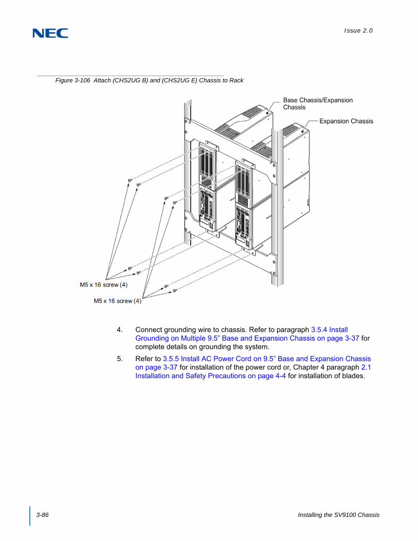
Issue 2.0
3-86 Installing the SV9100 Chassis
4. Connect grounding wire to chassis. Refer to paragraph 3.5.4 Install Grounding on Multiple 9.5” Base and Expansion Chassis on page 3-37 for complete details on grounding the system.
5. Refer to 3.5.5 Install AC Power Cord on 9.5” Base and Expansion Chassis on page 3-37 for installation of the power cord or, Chapter 4 paragraph 2.1 Installation and Safety Precautions on page 4-4 for installation of blades.
Figure 3-106 Attach (CHS2UG B) and (CHS2UG E) Chassis to Rack

Issue 2.0
SV9100 System Hardware Manual 3-87
SECTION 8 BATTERY CONNECTION
Two types of battery connection provide battery life during a power failure, the internal battery and an external battery with CHSG LARGE BATT BOX.
8.1 Installing the Internal Batteries 19” (CHS2UG) Chassis
An internal battery source using two batteries can be installed using the CHS2UG BATT MTG KIT (mounting kit) and CHS2U BATT CABLE INT (internal cabling).
CHS2UG BATT MTG KIT (Backup time = 10 Minutes/24 Terminals)
1. Power down the CHS2UG chassis
2. Disconnect AC power and grounding cable from rear of chassis.
3. Remove screws from battery access panel on rear of chassis.
IMPORTANT
Ensure the CHS2UG chassis is powered OFF.
Figure 3-107 Removing Battery Access Panel

Issue 2.0
3-88 Installing the SV9100 Chassis
4. Remove access panel containing the fan. Refer to Figure 3-108 Removing Access Panel and Figure 3-109 Access Panel Removed.
Figure 3-108 Removing Access Panel
Figure 3-109 Access Panel Removed

Issue 2.0
SV9100 System Hardware Manual 3-89
5. Using tie wraps, secure CHS2U BATT CABLE INT in cable guide bracket.
6. With supplied screw, install cable guide in chassis.
7. Install two 2.3 AH-12V batteries (locally procured) into the CHS2UG BATT MTG KIT (refer to Figure 3-112 Installing Two Batteries on page 3-90).
Figure 3-110 Secure Cable in Support Bracket
Figure 3-111 Installing Cable Support Guide
TIP
The first battery must be installed on the left side, then slid to the right due to an installation tab on the mounting kit.
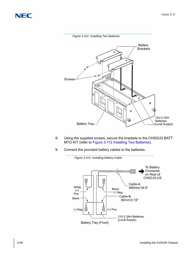
Issue 2.0
3-90 Installing the SV9100 Chassis
8. Using the supplied screws, secure the brackets to the CHS2UG BATT MTG KIT (refer to Figure 3-112 Installing Two Batteries).
9. Connect the provided battery cables to the batteries.
Figure 3-112 Installing Two Batteries
Figure 3-113 Installing Battery Cable

Issue 2.0
SV9100 System Hardware Manual 3-91
10. Connect CHS2U BATT CABLE INT to battery connector.
11. Install CHS2UG BATT MTG KIT into CHS2UG chassis and tighten the retaining screws.
Figure 3-114 Connecting CHS2U BATT CABLE INT
Figure 3-115 Installing Battery Tray into CHS2UG Chassis

Issue 2.0
3-92 Installing the SV9100 Chassis
12. Reinstall access panel containing the fan and secure with supplied screw.
13. Connect grounding and AC power cable.
8.2 Installing the External Batteries 19” (CHS2UG) Chassis
An optional (locally procured), external battery source can be used to provide power during a power failure.
CHSG LARGE BATT BOX (Backup time = Three Hours for 30 Terminals)
Figure 3-116 Installing the Access Panel
Table 3-5 CHSG LARGE BATT BOX Capacity
ConfigurationBattery Capacity
(Number of Batteries)
Number ofCHSG LARGE
BATT BOXSV9100
2U x 1 21AH (=3 sets of [2x12V-7AH]) 1
2U x 2 42AH (=6 sets of [2x12V-7AH]) 2
2U x 3 63AH (=9 sets of [2x12V-7AH]) 3
2U x 4 84AH (=12 sets of [2x12V-7AH]) 4
One CHSG LARGE BATT BOX can be used for 4 x 2U chassis for approximately 45
minutes.
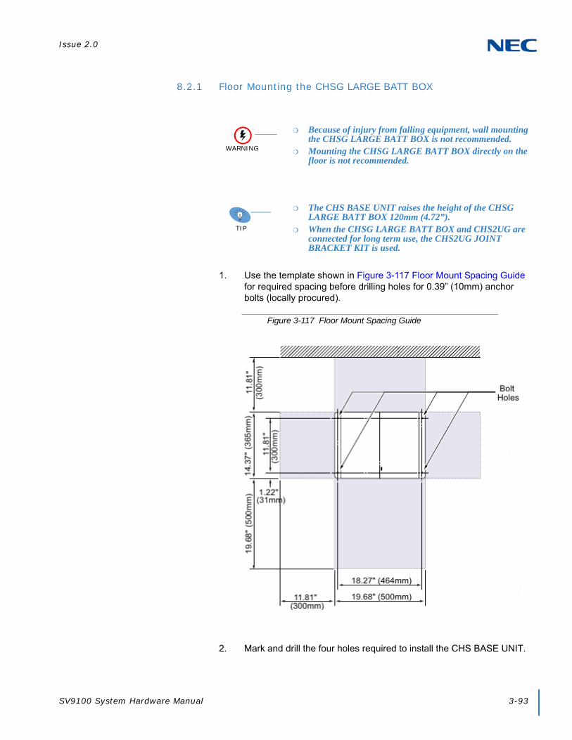
Issue 2.0
SV9100 System Hardware Manual 3-93
8.2.1 Floor Mounting the CHSG LARGE BATT BOX
1. Use the template shown in Figure 3-117 Floor Mount Spacing Guide for required spacing before drilling holes for 0.39” (10mm) anchor bolts (locally procured).
2. Mark and drill the four holes required to install the CHS BASE UNIT.
WARNING
Because of injury from falling equipment, wall mounting the CHSG LARGE BATT BOX is not recommended.
Mounting the CHSG LARGE BATT BOX directly on the floor is not recommended.
TIP
The CHS BASE UNIT raises the height of the CHSG LARGE BATT BOX 120mm (4.72”).
When the CHSG LARGE BATT BOX and CHS2UG are connected for long term use, the CHS2UG JOINT BRACKET KIT is used.
Figure 3-117 Floor Mount Spacing Guide

Issue 2.0
3-94 Installing the SV9100 Chassis
3. Align bolt holes in CHS BASE UNIT (see Figure 3-117 Floor Mount Spacing Guide on page 3-93) with holes drilled in floor and secure using four anchor bolts.
4. Align and install the CHSG LARGE BATT BOX on top of the CHS BASE UNIT.
5. Secure the CHSG LARGE BATT BOX to the CHS BASE UNIT using the CHS2UG JOINT BRACKET KIT. Refer to Figure 3-118 Installing the CHSG LARGE BATT BOX using the CHS2UG JOINT BRACKET KIT.
8.2.2 Battery Installation
1. Loosen screw on front of CHSG LARGE BATT BOX.
2. Swing cover outward and detach from CHSG LARGE BATT BOX.
Figure 3-118 Installing the CHSG LARGE BATT BOX using the CHS2UG JOINT BRACKET KIT
Figure 3-119 Removing CHSG LARGE BATT BOX Cover

Issue 2.0
SV9100 System Hardware Manual 3-95
3. Remove two screws from front of Battery Tray Suppressor.
4. Slide Battery Tray Suppressor outward to remove.
5. Slide Battery Tray(s) out of CHSG LARGE BATT BOX.
6. Loosen two screws and remove the Battery Tray Cover.
Figure 3-120 Removing Battery Tray Suppressor
Figure 3-121 Removing Battery Tray Cover

Issue 2.0
3-96 Installing the SV9100 Chassis
7. Remove two screws and remove the Battery Tray Bracket.
8. Refer to Figure 3-123 Battery Cable Connection Guide for connection of battery cable to battery terminals. Repeat for additional battery connection.
9. Install batteries into Battery Tray. Refer to Figure 3-124 Installing Battery Connection Cable.
Figure 3-122 Removing Battery Tray Bracket
WARNING
Incorrect Installation Of Batteries May Damage The Fuse Unit Or Cause Possible Fire.
Figure 3-123 Battery Cable Connection Guide

Issue 2.0
SV9100 System Hardware Manual 3-97
10. Using two screws, install the Battery Tray Bracket. Refer to Figure 3-122 Removing Battery Tray Bracket on page 3-96.
11. Insert Battery Connection Cable into cable guides. Refer to Figure 3-124 Installing Battery Connection Cable.
12. Install the Battery Tray Cover and tighten the two screws. Refer to Figure 3-124 Installing Battery Connection Cable.
13. Slide the Battery Trays into the CHSG LARGE BATT BOX.
14. Install the Battery Tray Suppressor while pulling the Battery Connection Cable(s) through the cutouts provided. Refer to Figure 3-125 Connecting Battery Cables on page 3-98. Secure with two screws.
15. Plug the Battery Connection Cable(s) into the Fuse Unit. Refer to Figure 3-125 Connecting Battery Cables on page 3-98.
Figure 3-124 Installing Battery Connection Cable

Issue 2.0
3-98 Installing the SV9100 Chassis
16. Insert tabs on cover into holes on CHSG LARGE BATT BOX. Slide the cover left until seated and tighten the screw.
8.2.3 CHSG LARGE BATT BOX to CHS2UG Connection
1. Power down the CHS2UG chassis.
2. Disconnect AC power cable from rear of chassis.
Figure 3-125 Connecting Battery Cables
Figure 3-126 Installing Cover Battery
WARNING
Ensure the CHS2UG chassis is powered OFF.

Issue 2.0
SV9100 System Hardware Manual 3-99
3. Remove fan access panel from rear of CHS2UG chassis.
4. Connect one end of Battery Connection Cable to Battery Connector on rear of Basic and Expansion chassis.
5. Connect other end of cable to Battery Connector on rear of CHSG LARGE BATT BOX chassis. Refer to Figure 3-129 Single CHSG LARGE BATT BOX Connection or Figure 3-130 Dual CHSG LARGE BATT BOX Connection on page 3-100.
Figure 3-127 Removing Fan Access Panel
Figure 3-128 Connecting External Battery to CHS2UG
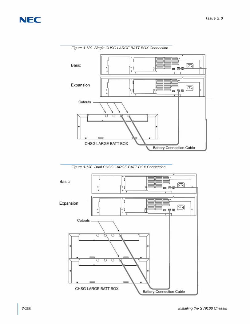
Issue 2.0
3-100 Installing the SV9100 Chassis
Figure 3-129 Single CHSG LARGE BATT BOX Connection
Figure 3-130 Dual CHSG LARGE BATT BOX Connection
Expansion
Basic
Basic
Expansion

Issue 2.0
SV9100 System Hardware Manual 3-101
6. Insert the access panel tab into the rear of the CHS2UG chassis running the Battery Connection Cable through the cutout. Secure panel with the retaining screw.
7. Connect grounding and AC power cables.
8. Apply power to chassis (refer to Chapter 4, 2.6 Powering Up the SV9100 System on page 4-9).
8.2.4 CHSG LARGE BATT BOX Fuse Replacement
1. Loosen screw on front of CHSG LARGE BATT BOX.
Figure 3-131 Install the Fan Access Panel
Figure 3-132 Removing CHSG LARGE BATT BOX Cover

Issue 2.0
3-102 Installing the SV9100 Chassis
2. Remove two screws from front of Battery Tray Suppressor (Refer to Figure 3-133 Removing Battery Tray Suppressor).
3. Slide Battery Tray Suppressor outward to remove.
4. Disconnect the Battery Connection Cables from the Fuse Unit.
5. Loosen two screws and pull Fuse Unit out of the CHSG LARGE BATT BOX.
6. Refer to Figure 3-135 CHSG LARGE BATT BOX Fuse Unit on page 3-103 for replacement of 8A or 30A fuses.
Figure 3-133 Removing Battery Tray Suppressor
Figure 3-134 Disconnecting Battery Cables

Issue 2.0
SV9100 System Hardware Manual 3-103
7. Slide the Fuse Unit into the and tighten the two screws (refer to Figure 3-134 Disconnecting Battery Cables on page 3-102).
8. Plug the Battery Connection Cables into the Fuse Unit.
Figure 3-135 CHSG LARGE BATT BOX Fuse Unit
Figure 3-136 Connecting Battery Cables

Issue 2.0
3-104 Installing the SV9100 Chassis
9. Insert tabs on cover into holes on CHSG LARGE BATT BOX. Slide the cover left until seated and tighten the screw.
8.3 Installing the CHS2UG B SMALL BATT BOX on the 9.5” CHS2UG B Chassis
An optional, CHS2UG B SMALL BATT BOX can be installed to provide external battery power to the CHS2UG GW and CHS2UG B chassis during a power failure. The short-term battery box will power the system for approximately 10 minutes.
8.3.1 CHS2UG B SMALL BATT BOX Installation
1. Power down the CHS2UG GW or CHS2UG B chassis.
2. Disconnect AC power cable from rear of chassis.
3. Align the Small Battery cable assembly with the grooves underneath the Base (CHS2UG B) chassis. Use the two M3 x 8 screws provided to secure the cable assembly in place (refer to Figure 3-138 Installing Battery Cable Assembly on page 3-105).
Figure 3-137 Installing Cover Battery
WARNING
Ensure the CHS2UG GW or CHS2UG B chassis is powered OFF.

Issue 2.0
SV9100 System Hardware Manual 3-105
4. Remove the battery connector cap on the Base chassis and connect the battery connection cable.
Figure 3-138 Installing Battery Cable Assembly
Figure 3-139 Installing Battery Connection Cable

Issue 2.0
3-106 Installing the SV9100 Chassis
5. Remove the two M3 x 8 screws from the Small Battery Box, then remove the battery cover (refer to Figure 3-140 Removing Battery Cover).
6. Place the two batteries into the Small Battery Box (refer to Figure 3-141 Installing Batteries on page 3-107).
Figure 3-140 Removing Battery Cover

Issue 2.0
SV9100 System Hardware Manual 3-107
7. Route battery cables a and b under the Small Battery Box tabs and connect to connectors A and B.
8. Insert tabs c and d of the battery cover into slots C and D of the Small Battery Box. Secure the cover using two M3 x 8 screws (refer to Figure 3-143 Installing Battery Cover on page 3-108).
Figure 3-141 Installing Batteries
Figure 3-142 Connecting Battery Cables

Issue 2.0
3-108 Installing the SV9100 Chassis
9. Pull the battery lock of the Small Battery Box forward to unlock it.
Figure 3-143 Installing Battery Cover
Figure 3-144 Unlocking the Small Battery Box

Issue 2.0
SV9100 System Hardware Manual 3-109
10. Align the Small Battery Box with the grooves at the top and bottom of the Base chassis and slide into position.
11. Push the battery lock in, then connect the battery cable.
Figure 3-145 Installing Small Battery Box
Figure 3-146 Locking the Small Battery Box

Issue 2.0
3-110 Installing the SV9100 Chassis
12. Connect grounding wire to chassis. Refer to Chapter 4 paragraph 3.5 Installing the 9.5” Base (CHS2UG B) and Expansion (CHS2UG E) Chassis on page 3-24 for complete details on grounding the system
13. Refer to 3.5.5 Install AC Power Cord on 9.5” Base and Expansion Chassis on page 3-37 for installation of the power cord or, Chapter 6 paragraph 2.1 Installation and Safety Precautions on page 4-4 for installation of blades
14. To power on the 9.5” chassis, refer to Chapter 4, 2.6 Powering Up the SV9100 System on page 4-9.
8.3.2 CHS2UG B SMALL BATT BOX Fuse Replacement
1. Correct the issue which caused the fuse problem.
2. Disconnect AC power cable from rear of chassis.
3. Unplug battery cables a and b from connectors A and B of the Small Battery Box.
WARNING
Only replace fuses of the same rating. Fuses may be hot, use caution when replacing them.
WARNING
Replacing fuses without first correcting the issue could cause a fire and/or electric shock hazard.
WARNING
Make sure to unplug the unit from the electrical outlet prior to removing the connection cables in the battery box unit.
Figure 3-147 Disconnecting the Battery Cables

Issue 2.0
SV9100 System Hardware Manual 3-111
4. Remove and replace the fuse as needed.
5. Reconnect battery cables a and b to connectors A and B.
6. To replace the battery, refer to section 8.3.1 CHS2UG B SMALL BATT BOX Installation on page 3-104.
8.4 Installing the External Batteries (CHSG LARGE BATT BOX) to the 9.5” Gateway (CHS2UG GW) or Base (CHS2UG B) Chassis
An optional, CHSG LARGE BATT BOX can be installed to provide external battery power to the CHS2UG GW chassis during a power failure. The long-term battery box powers the system for approximately three hours.
8.4.1 CHSG LARGE BATT BOX Installation
To install the batteries in the CHSG LARGE BATT BOX, refer to Chapter 3, section 8.2.2 Battery Installation on page 3-94.
Figure 3-148 Removing the Fuse
WARNING
Because of injury from falling equipment, wall mounting the CHSG LARGE BATT BOX is not recommended.
Mounting the CHSG LARGE BATT BOX directly on the floor is not recommended.
Due to possible water damage, floor mounting the 9.5” chassis is not recommended by NEC.
NOTE The CHS BASE UNIT raises the height of the CHSG LARGE BATT
BOX 120mm (4.72”).

Issue 2.0
3-112 Installing the SV9100 Chassis
8.4.2 CHSG LARGE BATT BOX to 9.5” Gateway (CHS2UG GW) or Base (CHS2UG B) Chassis Connection
1. Power down the CHS2UG GW or CHS2UG B chassis.
2. Disconnect AC power cable from rear of chassis.
3. From the back of the 9.5” chassis, remove the black plastic square covering the two-prong battery terminal leads (refer to Figure 3-149 9.5” Chassis (Rear View)).
4. Connect one end of Battery Connection Cable to Battery Connector on rear of 9.5” chassis.
5. Connect other end of cable to Battery Connector on rear of CHSG LARGE BATT BOX chassis (refer to Figure 3-150 CHSG LARGE BATT BOX to CHS2UG GW or CHS2UG B Connection on page 3-113).
WARNING
Ensure the CHS2UG GW or CHS2UG B chassis is powered OFF.
Figure 3-149 9.5” Chassis (Rear View)
Ground AC InletFor External Battery (12V Connection)
CHS2UG

Issue 2.0
SV9100 System Hardware Manual 3-113
6. Reconnect AC power cable to rear of 9.5” chassis.
7. To power on the 9.5” chassis, refer to Chapter 4, 2.6 Powering Up the SV9100 System on page 4-9.
8.4.3 CHSG LARGE BATT BOX Fuse Replacement
To replace the fuse(s) in the CHSG LARGE BATT BOX, refer to Chapter 3, section 8.2.4 CHSG LARGE BATT BOX Fuse Replacement on page 3-101.
SECTION 9 POWER SUPPLY
Figure 3-150 CHSG LARGE BATT BOX to CHS2UG GW or CHS2UG B Connection
WARNING
Do not attempt to replace the power supply on the CHS2UG or CHS2UG GW chassis. The MPS7101 is not a field replaceable part. If the power supply fails, contact NEC.

Issue 2.0
3-114 Installing the SV9100 Chassis
SECTION 10 REMOVE AND INSTALL COOLING FAN
If required, the cooling fan installed in the CHS2UG chassis can be removed and replaced. Follow the procedure below for the CHS2UG chassis.
10.1 CHS2UG Chassis
10.1.1 Remove Cooling Fan
1. Ensure the chassis is powered down.
2. Loosen retaining screw from chassis access panel.
3. Swing access panel outward and unplug fan power cable.
WARNING
To reduce the possibility of electrical shock or damage to equipment, NEC recommends powering off the chassis and disconnecting the AC cable from the power source before removing the chassis cover.
WARNING
To reduce the possibility of damage to equipment, the installer must wear a grounded wrist strap to protect the equipment from static electricity.
Figure 3-151 19” Chassis Access Panel
Retaining Screw
Figure 3-152 Opening Chassis Access Panel (19” Chassis)
Fan Power Cable Plug

Issue 2.0
SV9100 System Hardware Manual 3-115
4. Remove chassis access panel from rear of chassis.
5. Remove cabling from retention clips.
6. Remove two screws securing fan to access cover. Keep screws for use when installing replacement fan [refer to Figure 3-153 Chassis Access Panel Removed (19” Chassis)].
10.1.2 Install Cooling Fan
1. Align replacement fan with holes and secure with two screws [refer to Figure 3-153 Chassis Access Panel Removed (19” Chassis)].
2. Install cabling into retention clips [refer to Figure 3-153 Chassis Access Panel Removed (19” Chassis) on page 3-115].
3. Insert access panel hinges into slots on rear of chassis.
4. Plug fan power cable into three prong plug [refer to Figure 3-152 Opening Chassis Access Panel (19” Chassis) on page 3-114].
5. Reinstall access cover and secure with retaining screw (refer to Figure 3-151 19” Chassis Access Panel on page 3-114).
Figure 3-153 Chassis Access Panel Removed (19” Chassis)

Issue 2.0
3-116 Installing the SV9100 Chassis

SV9100 System Hardware Manual 4-1
Chapter 4
UNIVERGE® SV9100
Installing the SV9100 Blades
SECTION 1 GENERAL INFORMATION
This chapter contains information to help the technician install the blades for the UNIVERGE SV9100 system. The technician should be familiar with this section before installing any equipment.
1.1 Slot Locations
Each CHS2UG has six slots. In the Controlling Chassis, the GCD-CP10 (for Key Systems) must be installed in the first slot (slot 1). In the CHS2UG GW and CHS2UG B, the GCD-CP10 must be installed in the first slot (slot 1).
Slot Locations in the CHS2UG (19” Controlling Chassis):
Slot 1 – dedicated for the CPU
Slots 2~6 – universal
Slot Locating in the CHS2UG (19” Expansion Chassis):
Slots 1~6 are universal. (i.e., any type of blade except the CPU can be installed in these slots).
Slot Locations in the CHS2UG GW and CHS2UG B Base (9.5” Chassis):
Slot 1 – CPU
Slots 2 and 3 – universal
Slot Locations in the 9.5” CHS2UG B and CHS2UG E (Controlling Chassis with CPU):
Slot 1 – CPU
Slots 2~6 – universal
Slot Locations in the 9.5” CHS2UG B and CHS2UG E (Expansion Chassis no CPU):
Slots 1~6 – universal

Issue 2.0
4-2 Installing the SV9100 Blades
Figure 4-1 19” Chassis CPU and Expansion Slot Locations
Controlling ChassisCPU Slot
Expansion ChassisGPZ-BS11 Slot
Figure 4-2 9.5” Gateway Chassis CPU Location
CPU

Issue 2.0
SV9100 System Hardware Manual 4-3
Figure 4-3 9.5” Base and Expansion Chassis CPU Location
CPU
Base ChassisCHS2UG B
CPU
GPZ-BS10 or GPZ-BS11 Slot
Base ChassisCHS2UG B
Expansion ChassisCHS2UG E

Issue 2.0
4-4 Installing the SV9100 Blades
SECTION 2 INSTALLATION
Pre-installation planning is essential. Advanced planning minimizes installation time, cost, and disruption of the customer business activities.
2.1 Installation and Safety Precautions
Never install telephone wiring during a lightning storm.
Never install telephone jacks in wet locations unless the jack is specifically designed for wet locations.
Never touch uninsulated telephone wires or terminals unless the telephone line is disconnected at the network interface.
Use caution when installing or modifying telephone lines.
Ground the Controlling and Expansion chassis before installing or removing the blades.
The Expansion Chassis must be installed with the system power OFF.
Do not touch the blade components.
Carry the blade in a conductive polyethylene bag to prevent static electricity until ready to install the blade.
When installing or removing the blades from the chassis, the installer must wear a grounded wrist strap to protect the blade from static electricity.
Although it is recommended to install the blades with the system power OFF, most blades can be installed hot except for the following that must be installed with the power OFF:
GCD-CP10
GPZ-BS10 and GPZ-BS11
WARNING
Observe the following precautions when installing the blades to avoid static electricity damage to hardware or exposure to hazardous voltages.

Issue 2.0
SV9100 System Hardware Manual 4-5
2.2 Installing an Extension or Trunk Blade
2.2.1 Installing the Blades
To install an extension/trunk blade with the system running:
1. Insert the blade in the guide rail and push it securely into position. Tighten the thumb screw on either side of the blade.
2. The Status LED starts flashing when the blade starts processing (15 seconds).
Figure 4-4 Inserting Blades in the 19” Chassis
Figure 4-5 Inserting Blades in the 9.5” Chassis
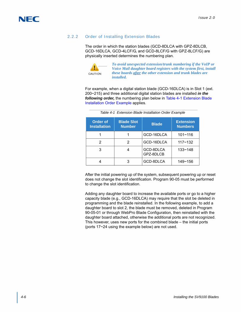
Issue 2.0
4-6 Installing the SV9100 Blades
2.2.2 Order of Installing Extension Blades
The order in which the station blades (GCD-8DLCA with GPZ-8DLCB, GCD-16DLCA, GCD-4LCF/G, and GCD-8LCF/G with GPZ-8LCF/G) are physically inserted determines the numbering plan.
For example, when a digital station blade (GCD-16DLCA) is in Slot 1 (ext. 200~215) and three additional digital station blades are installed in the following order, the numbering plan below in Table 4-1 Extension Blade Installation Order Example applies.
After the initial powering up of the system, subsequent powering up or reset does not change the slot identification. Program 90-05 must be performed to change the slot identification.
Adding any daughter board to increase the available ports or go to a higher capacity blade (e.g., GCD-16DLCA) may require that the slot be deleted in programming and the blade reinstalled. In the following example, to add a daughter board to slot 2, the blade must be removed, deleted in Program 90-05-01 or through WebPro Blade Configuration, then reinstalled with the daughter board attached, otherwise the additional ports are not recognized. This however, uses new ports for the combined blade – the initial ports (ports 17~24 using the example below) are not used.
CAUTION
To avoid unexpected extension/trunk numbering if the VoIP or Voice Mail daughter board registers with the system first, install these boards after the other extension and trunk blades are installed.
Table 4-1 Extension Blade Installation Order Example
Order of Installation
Blade Slot Number
BladeExtension Numbers
1 1 GCD-16DLCA 101~116
2 2 GCD-16DLCA 117~132
3 4 GCD-8DLCAGPZ-8DLCB
133~148
4 3 GCD-8DLCA 149~156
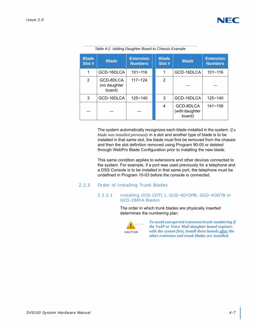
Issue 2.0
SV9100 System Hardware Manual 4-7
The system automatically recognizes each blade installed in the system. If a blade was installed previously in a slot and another type of blade is to be installed in that same slot, the blade must first be removed from the chassis and then the slot definition removed using Program 90-05 or deleted through WebPro Blade Configuration prior to installing the new blade.
This same condition applies to extensions and other devices connected to the system. For example, if a port was used previously for a telephone and a DSS Console is to be installed in that same port, the telephone must be undefined in Program 10-03 before the console is connected.
2.2.3 Order of Installing Trunk Blades
2.2.3.1 Installing GCD-COT( ), GCD-4DIOPB, GCD-4ODTB or GCD-2BRIA Blades
The order in which trunk blades are physically inserted determines the numbering plan.
Table 4-2 Adding Daughter Board to Chassis Example
Blade Slot #
BladeExtension Numbers
Blade Slot #
BladeExtension Numbers
1 GCD-16DLCA 101~116 1 GCD-16DLCA 101~116
2 GCD-8DLCA(no daughter
board)
117~124 2— —
3 GCD-16DLCA 125~140 3 GCD-16DLCA 125~140
— — —4 GCD-8DLCA
(with daughter board)
141~156
CAUTION
To avoid unexpected extension/trunk numbering if the VoIP or Voice Mail daughter board registers with the system first, install these boards after the other extension and trunk blades are installed.

Issue 2.0
4-8 Installing the SV9100 Blades
For example, if four blades are installed in the following order, the numbering plan below applies.
2.2.3.2 Installing GCD-PRTA (PRI/E1) Blades
The GCD-PRTA (PRI/E1) Interface blade uses the first block of 24 consecutive trunks.
For example, if a GCD-4COTA blade with GPZ-4COTE daughter board is installed for trunks 1~8, the GCD-PRTA (PRI/E1) blade automatically uses trunks 9~38. If GCD-4COTA with GPZ-4COTE is installed for trunks 1~8 and 17~24, the GCD-PRTA (T1/PRI) blade uses trunks 25~54. The GCD-PRTA (PRI/E1) blade cannot use trunks 9~16 (even if available) since they are not part of a consecutive block of 30 trunks.
2.3 Remove an Extension or Trunk Blade
Any blade, EXCEPT the ones listed below can be removed while the system is powered up. To remove any blade listed below, the system must first be powered down.
GCD-CP10
GPZ-BS10 and GPZ-BS11
To remove an extension/trunk blade with the system running:
1. When LED 2 is extinguished, all extensions/trunks are idle.
2. Loosen the thumb screw on either side of the blade and pull it out of the chassis.
Table 4-3 Trunk Blade Installation Order Example
Order of Installation
Blade Slot Number
Blade Line Circuits
1 4 GCD-4COT( ) withGPZ-4COT( )
1~8
2 5 GCD-4COT( ) 9~12
3 7 GCD-ODTB 13~16
4 6 GCD-ODTB 17~20

Issue 2.0
SV9100 System Hardware Manual 4-9
2.4 Uninstalling a Blade Slot Through Software
The installer can turn off (busy out) and delete (remove from software) blade slots in the Controlling and Expansion Chassis in programming for port renumbering or to replace it with a different blade. Deleting a blade may affect blade slot programming ability. Refer to Program 90-05 in the UNIVERGE SV9100 Programming Manual for detailed information.
2.5 Blade Capacities
The universal architecture of the UNIVERGE SV9100 provides flexibility when installing blades. With the exception of the GCD-CP10, GPZ-BS10, and GPZ-BS11 blades, any blade can be installed in any slot. Table 2-6 SV9100 Maximum 9.5” Gateway and 19” System Capacities – Blades on page 2-12 and Table 2-7 SV9100 Maximum 9.5” Base and Expansion System Capacities – Blades on page 2-14 provide a list of the blades and the maximum capacities with various chassis configurations.
2.6 Powering Up the SV9100 System
2.6.1 Performing a Cold Start
This section describes the process for starting the system (19” and 9.5” chassis) for the first time or starting a system that has been turned off.
To perform a cold start:
1. Turn the system power off.
2. Once the system has powered down, push in and hold the Load button.
3. Turn the power switch back on to power the system back up.
With a multi-chassis system, turn on the Expansion Chassis power supply, then the Controlling Chassis power supply.
4. Continue holding the Load button for approximately three seconds or until LED 2 starts flashing red.
5. Release the Load button.
6. When the system has completed reloading the software (two minutes), the Status LED is flashing on the GCD-CP10.
CAUTION
IMPORTANT CONSIDERATIONS
System software is loaded from flash memory, and customer data is from RAM memory.
To avoid extension and trunk renumbering, if certain blades are recognized first, remove them from their respective slots until the system has been reset. Then, slot the blade cards in the correct order to retain the proper system numbering. (Use Program 10-03 prior to performing a cold start to record the current slot definitions.)

Issue 2.0
4-10 Installing the SV9100 Blades
2.6.2 Performing a Hot Start
The section describes how to load system software from flash memory and customer data from RAM memory.
1. Turn the system power off.
2. After it has powered down, press the button again to power the system back up. Wait approximately two minutes.
3. When the system has completed reloading the software, the Status LED is flashing on the GCD-CP10.
2.6.3 Resetting the System
This section describes resetting a system that is running. Observe the important information listed below.
To reset the system:
2.6.3.1 Initial Programming
The system can be programmed using three methods:
Programming using a multiline terminal
PC Programming
Web Programming
To program using a multiline terminal, enter programming mode:
1. Go to any working display telephone.
2. Do not lift the handset.
In a newly installed system, use extension (port 1).
3. Press Speaker.
4. # # .
5. Dial the system password + Transfer.
CAUTION
IMPORTANT CONSIDERATIONS
System software is loaded from flash memory, and customer data is from RAM memory.
Password

Issue 2.0
SV9100 System Hardware Manual 4-11
2.6.3.2 Port Defaults
With the default settings, the ports are assigned as follows:
In the initial configuration:
All Programmable Function keys are line keys (e.g., key 1 is line 1).
All trunks are loop start DTMF.
2.6.3.3 Setting Up Extension Circuit Types
Run Program 10-03 to set up extension circuit types as required. The system automatically detects and assigns most circuit types when the device is connected.
1. Dial 10-03-01.
2. Press TRANSFER to Select the slot, port or channel (with ESIU Blades) to be programmed.
3. Set the terminal type or option as needed.
If the system has DSS Consoles, Program 30-02 must be used to define DSS extension assignments.
As the system recognizes the extension devices automatically, when replacing the connected device, it must be undefined in Program 10-03 prior to connecting the new device. For example, if a port was previously used for a telephone and a DSS Console is to be installed in that same port, the telephone must first be undefined in Program 10-03 before the console is connected.
2.6.3.4 Saving Your Configuration
When programming is completed, to exit out of the program option and save changes to the GCD-CP10:
1. Press EXIT to exit the program options, if needed.
2. Press Speaker. Saving System Data is displayed if changes were made to system programming.
3. The display shows Complete Data Save when completed and the telephone becomes idle.
Table 4-4 Default Port Settings
Station Ports:Port 1~300 : 200~499Port 301~960 : 5000~5659
Virtual Station Ports:
Port 1~99 : 201~299Port 100~512 : No Setting
Trunk Ports: 1~400

Issue 2.0
4-12 Installing the SV9100 Blades
2.6.3.5 Backing Up/Restoring a Database
As a precaution, it is recommended that the customer database be saved prior to updating the system software. There are two methods to save the database – either use the PCPro application or save directly to USB Memory on GCD-CP10. Using PCPro, download the database and save the file on the PC hard drive. To save the database using a blank USB Memory, insert the USB Memory into the USB Port on the GCD-CP10 blade and, using Program 90-03, save the software. Due to the file naming structure, note that a USB Memory can hold only one customer database (each database is saved to a directory called DATA – this directory is overwritten if a second database is saved to the same card). Each database to be saved requires its own separate card (unless you choose to rename the directory after it is saved, then rename it back to DATA when you need to access the database).
If the customer data needs to be reloaded, the method for restoring the database is determined by how the database was saved. Using PCPro, the customer database is uploaded using the Upload option in the application. If the database is stored on a USB Memory, use Program 90-04, with the database to be restored installed in the USB Port on the GCD-CP10 blade.
When restoring a database file, as the slot definitions may be different, remove all blades from the system except the GCD-CP10 and the GCD-8DLCA/GCD-16DLCA in slot 2. After the system is reset, blades can be installed again. Program 10-03 or Program 90-04 can be used prior to updating to record the current slot definitions. If the blades are not removed, the trunk and extension port assignments may be reassigned, depending on which blade syncs up with the system first.
After reloading the customer data to the system, exit programming mode (this could take a minute or more to save the database), then reset the system by powering down and back up. If the system is not reset, not all the uploaded programming changes are in effect. Wait a few minutes for the programming to take affect before accessing any line or special system feature. Otherwise, some unusual LED indications may be experienced. To prevent the USB Memory from possibly being overwritten, remove the card after reloading the database.
Issue 2.0
SV9100 System Hardware Manual 4-13
2.6.4 Performing a Software Upgrade
This section describes the procedure to perform a software upgrade on the GCD-CP10.
To perform a system software and firmware upgrade:
1. Turn the system power off.
2. After the system powers down, insert the USB Memory containing the software upgrade into the USB port on the GCD-CP10.
3. Push in and hold the Load button.
4. Turn the system power on.
5. Continue holding the Load button for approximately 10 seconds or until Status LED D23 begins flashing red.
6. Release the Load button.
7. Wait until the Status LEDs on the GCD-CP10 have the following indications (approximately two minutes):
LED D20: Flashing RedLED D21: Flashing RedLED D22: Flashing RedLED D23: Steady Green
8. Turn the system power off and remove the USB Memory.
CAUTION
IMPORTANT CONSIDERATIONS
To save customer data prior to updating, a blank USB Memory is required. Insert the USB Memory into the USB Port on the GCD-CP10 blade. Use Program 90-03 to save the software to the USB Memory. Note that a USB Memory can hold only one customer database. Each database to be saved requires its own separate USB Drive. Use Program 90-04, with the database to be restored installed in the GCD-CP10, to reload the customer data if necessary.
After uploading programming data to the system using Program 90-04, exit programming mode (this could take a minute or more to save the database), then reset the system by powering down and back up. Wait a few minutes for the programming to take affect before accessing any line or special system feature. Otherwise some unusual LED indications may be experienced. To prevent the USB Memory from possibly being overwritten, remove the USB Memory after downloading the database.
When restoring a database file, as the slot definitions may be different, remove all blades from the system except the GCD-CP10 and GCD-8DLCA/GCD-16DLCA in slot 2. After the system is reset, the blades can be reinstalled. Use Program 10-03 prior to updating to record the current slot definitions.

Issue 2.0
4-14 Installing the SV9100 Blades
9. Turn the system power back on.
10. When the system has completed reloading the software, the Status LED begins flashing on the GCD-CP10. The remaining four LEDs are off.
To confirm the new software version is installed, press the FEATURE + 3 keys on any display multiline terminal to view the system version number.
The existing system software in the flash memory is replaced, but the customer data (stored in the RAM) is saved.

Issue 2.0
SV9100 System Hardware Manual 4-15
SECTION 3 COMMON CONTROL BLADES
The blades described in this section control the common functions of the chassis.
3.1 GCD-CP10 (SV9100 Central Processing Unit)
Figure 4-6 GCD-CP10 Blade Layout

Issue 2.0
4-16 Installing the SV9100 Blades
3.1.1 Description
The GCD-CP10 controls all the functions and operations of the SV9100 system using the system software loaded into the GCD-CP10 memory. The system software can be upgraded as new software becomes available.
One GCD-CP10 blade must be installed in the Controlling Chassis.
The GCD-CP10 functions are:
Music on Hold tone Circuit, External Source Control Circuit
Voice Mail/VRS Interface Circuit
VM recording time
SD-A1 memory card: 15 hours
SD-B1 memory card: 120 hours
Number of mail boxes: 896
System Program and System Data Storing Memory Circuit
SD Card/USB Interface Circuit
Ethernet Interface Circuit
Figure 4-7 GCD-CP10 Blade with Daughter Boards Installed

Issue 2.0
SV9100 System Hardware Manual 4-17
GPZ-BS10/GPZ-BS11 Interface Circuit
Main Processing 32-Bit CPU Circuit (P1015 @ 533 MHz)
Time Switch, Optional Blade Control Circuit
Backboard Interface Circuit
The GCD-CP10 provides:
400 trunk ports maximum
896 extension ports maximum
896 ports digital/IP extensions maximum
368 analog ports maximum
512 virtual extensions
Connection for GPZ-IPLE Daughter Board
Supports TAPI 2.x
One Green Status LED
Four Red Status LEDs
Five diagnostic LEDs which indicate the status of various system functions
During normal operation, the RUN LED is flashing and the remaining LEDs are off
Time Division Multiplex Switch (TDM Switch)
Digital Phase Locked Loop (DPLL)
Tone Generator
Tone Processing DSP
Connection for Memory Module
Digital Signal Processor (DSP)
DTMF Tone Sender
DTMF Tone Receiver
Dial Tone Generator (DTG)
The GPZ-BS10 provides 64 channels for Telephony Resource (e.g., DTMF Receiver, Caller ID Receiver, and Call Progress Tone Detection)
System Tone Sender
MF Receiver
MF Sender
MFC Tone Sender

Issue 2.0
4-18 Installing the SV9100 Blades
MF Signal Sender (Sends caller information to CO for E911)
Call Progress Tone Detection
C-Channel Control
Conference Circuits: 64 Channel (when built-in modem is enabled) or 96 Channel (when built-in modem is disabled)
Caller ID Receiver: 80 Channels
A load switch which is used for initial system startup, resetting the system, or when upgrading system software
One Serial Port (NEC production use only)
One SD/SDHC Card (VM) connector
One USB Port – USB 1.1/USB 2.0
Memory size – minimum of 32MB (normally 512MB or 1GB) should be used.
USB device power consumption is less than 200mA (1W).
One Gbit Ethernet Port for VoIP function
Background Music/EXSP Control Port
Status LED
Two Audio Input/Output Terminals
One Music On Hold External Source
High-Level Data Link Control (HDLC) Packet Processing
Real Time Clock (tolerance 30 seconds/month)
Call Control Server (ex: Conference Bridge Server, Voice Mail Server, SIP Server, RTP Forwarding, VoCoder Conversion)
One lithium battery (CR2032) which provides battery back-up of system data and RAM memory for approximately 30 months.
The GCD-CP10 functions provided are:
Call Control Server
Conference Bridge Server
Voice Mail Server (voice mail requires proper licensing)
SIP Server
RTP Forwarding
VoCoder Conversion

Issue 2.0
SV9100 System Hardware Manual 4-19
3.1.2 Installation
Each SV9100 system must have the GCD-CP10 installed in Slot 1 of the Controlling Chassis.
3.1.2.1 Battery Installation and Removal
Battery Installation
1. Install the battery (CR2032 3.0V coin-type lithium battery) onto the GCD-CP10. The polarity + symbol must be on top as illustrated in Figure 4-8 GCD-CP10 Battery Installation.
CAUTION
IMPORTANT CONSIDERATIONS
The chassis power must be off when installing or removing the GCD-CP10.
After removing a previously installed GCD-CP10, handle the blade, carefully, from the edges. If certain solder points/resistors are touched on the back of the blade, some RAM/temporary memory may be lost (e.g., time, date, user-defined settings, etc.)
Do not remove the CPU chip installed on the GCD-CP10 blade.
WARNING
Keep away from open flame. Avoid excessive heat.
Verify polarity (+, -) when installing battery.
Do not short the electrodes (+, -) with metals such as wire.
Do not puncture, crush or solder the battery.
Figure 4-8 GCD-CP10 Battery Installation

Issue 2.0
4-20 Installing the SV9100 Blades
2. Push down on the battery, opposite from the plus (+) symbol (refer to Figure 4-8 GCD-CP10 Battery Installation).
Battery Removal
1. Ensure backup of SRAM data on GCD-CP10.
When removing the backup battery, SRAM data and system clock are initialized. Use the following to store the SRAM data (Reconfigure the system clock after replacing the battery).
2. Power off the system and remove the GCD-CP10 from the chassis.
3. Carefully lift the battery from the socket.
4. Install the replacement battery (refer to 3.1.2.1 Battery Installation and Removal on page 4-19).
5. Install the blade into the chassis and power on the system.
6. Reset the system (press RESET on the front of the GCD-CP10 blade).
7. Configure the system clock using the PCPro “Quick Setup” menu or the command (CM02).
CAUTION
Before removing the GCD-CP10 from the chassis to install or replace a battery, ensure the system is powered Off.
When removing the backup battery, SRAM data and system clock are initialized. Make a backup of the SRAM in advance and configure the system clock after battery replacement.
IMPORTANT
Replace the battery every 6 years.
Contact the reseller where you bought the product for a replacement battery.
CAUTION
The following SRAM data types are important for the client. If stored, this procedure must be used to restore the data.
Billing memory
SMDR Billing data
Table 4-5 SRAM Data Types
SRAM Data Measure
Fault InformationRead the fault information using the PCPro “Fault
Display” menu.
OAI FLF MemorySave the memory by specifying “DBM data (PHS/OAI)” in the PCPro “System Data Save/Load Verify” menu.
Billing Memory Print the billing memory using an external printer.
SMDR Billing Data Delete the billing data using SMDR/CR1000.

Issue 2.0
SV9100 System Hardware Manual 4-21
8. Load the SRAM data saved in step 1, above.
From the PCPro “System Data Save/Load/Verify” menu load the data from the specified file.
- OAI FLF Memory
Battery replacement is complete.
3.1.2.2 GPZ-IPLE Daughter Board Installation
1. Refer to Figure 4-10 Installing the GPZ-IPLE Daughter Board on page 4-28 to install the GPZ-IPLE daughter board, if required.
2. Ensure the power supply is OFF, then slide the GCD-CP10 into Slot 1 in the Controlling Chassis.
3.1.2.3 SD-A1/SD-B1 Installation
1. Refer to Figure 4-6 GCD-CP10 Blade Layout on page 4-15 to install the SD-A1 or SD-B1 SD card, if required.
2. Ensure the power supply is OFF, then slide the SD card (label side up) into the slot until it clicks.
To remove: Carefully push on the SD card until it clicks and release. Card can be removed from the slot.
3.1.2.4 Background Music (BGM) or Music on Hold (MOH)
1. If external Background Music (BGM) or Music on Hold (MOH) is being installed, plug the cable into the AUX1 or AUX2 pin jack connector on the GCD-CP10. The other end of the cable plugs into the music source.
Refer to the PGDAD in Chapter 9, section 2.1 Using a PGDAD on page 7-1 for details on connecting to a music source.
When the system software is upgraded, the flash memory is updated with the new software version. Either the Hot or Cold start-up method can be used or the system can be upgraded using system software. Refer to 2.6.1 Performing a Cold Start on page 4-9, 2.6.2 Performing a Hot Start on page 4-10, or 2.6.4 Performing a Software Upgrade on page 4-13.
Customer information is stored in the RAM memory which is restored after a power failure is cleared. The lithium battery in the system saves the RAM memory when power is lost.

Issue 2.0
4-22 Installing the SV9100 Blades
3.1.3 Switch Settings
Refer to Table 4-6 GCD-CP10 Switch Settings for system restart/system reset and with system power on. Figure 4-6 GCD-CP10 Blade Layout on page 4-15 shows the location of the LOAD (S5) switch on the GCD-CP10 blade.
Table 4-6 GCD-CP10 Switch Settings
USB Memory Status Operation
SwitchS5 – LOAD
Switch
With a system restart or a system reset while holding the LOAD (S5) switch:
When USB Memory is not installed:
Cold Start occurs. Database default occurs
When USB Memory is installed:
USB Memory contents loaded.
When an unauthorized USB device is installed:
System does not start and an Illegal USB device is connected alarm is recorded.
Table 4-7 GCD-CP10 Switch 4/6 Settings
Configuration Notes
SW4-1 ON Not Used
SW4-2OFF Test Mode
ON = Test ModeOFF = Normal
SW4-3OFF RS232C Select
ON = UseOFF = Not Used
SW4-4ON Reset Configuration
ON = NormalOFF = ICE Mode
S6 SENSE Switch Not Used

Issue 2.0
SV9100 System Hardware Manual 4-23
3.1.4 LED Indications
The LEDs on the GCD-CP10 indicate the following:
RUN (D23) = The CPU is operating (green)
D20, and D21 = Alarms (red)
D22 = SD Memory Card access/Alarm indication (red)
D25 = The USB memory connection status (red)(LED off when no USB memory installed)
D24 = Not Used
Refer to Program 90-10: System Alarm Setup for details on assigning alarm LEDs.
Table 4-8 GCD-CP10 LED Indications provides a list of each LED and associated operation and status indications. Refer to Figure 4-6 GCD-CP10 Blade Layout on page 4-15 for the location of the LEDs on the GCD-CP10.
Table 4-8 GCD-CP10 LED Indications
LED IndicationStatus
RUN (D23) D20 D21 D22 D25
Blinking Off Off Off On Steady When USB Memory is
Installing
System operating normally
Off Off Off Off Blinking Boot is starting
Off On Off Off Off Initializing the disk or formatting
Blinking Blinking Off Access Blink
On Steady When USB Memory is
Installing
Boot program is initializing in the flash memory
Off On On Access Blink
On Steady When USB Memory is
Installing
Reading system software
Off On Off Access Blink
On Steady When USB Memory is
Installing
Upgrading system software
On Blinking Blinking Blinking On Steady When USB Memory is
Installing
Finish formatting (SRAM, Flash)
Blinking Off Off Off Off DRAM error
Blinking Off Off On On Steady When USB Memory is
Installing
FPGA version error

Issue 2.0
4-24 Installing the SV9100 Blades
3.1.5 Connectors
Table 4-9 GCD-CP10 Connections describes each connector on the GCD-CP10, Table 4-10 GCD-CP10 RJ45 Cable Connector Pin-Outs describes the pin-outs for connectors on the GCD-CP10. Refer to Figure 4-6 GCD-CP10 Blade Layout on page 4-15 for the location of the connections on the GCD-CP10 blade.
Blinking Off On Off On Steady When USB Memory is
Installing
SRAM error
Blinking Off On On On Steady When USB Memory is
Installing
SD memory booting error
Blinking On On On On Steady When USB Memory is
Installing
SD memory data error
Blinking Blinking Blinking Blinking On Steady When USB Memory is
Installing
Reading error of system program
Blinking On Off Off On Steady When USB Memory is
Installing
Error: Major alarm occurred
Blinking Blinking Off Off On Steady When USB Memory is
Installing
Error: Minor alarm occurred
On Off Off Off Off System starting up
Table 4-8 GCD-CP10 LED Indications (Continued)
LED IndicationStatus
RUN (D23) D20 D21 D22 D25
Table 4-9 GCD-CP10 Connections
Connector Connector Description
J13 USB Memory Connection (used for upgrading software or downloading system data)
J4 Ethernet Cable Connection (for PCPro or WebPro, CTI, ACD MIS, IP Phone)
J11/J12 Pin Jack for External Source Connection (External MOH, External Speaker, etc.)
J10 External Source Control Connection
J6/S4 Used for Debug

Issue 2.0
SV9100 System Hardware Manual 4-25
J7 SD Memory Card Connection
J9 Backboard Connection
J14 GPZ-IPLE Connection
J28 Lithium Battery Socket - for backup of SRAM data and RTC (Real Time Clock) data
LOAD (S5) Load Switch
S6 SENSE Switch
Table 4-9 GCD-CP10 Connections (Continued)
Connector Connector Description
Table 4-10 GCD-CP10 RJ45 Cable Connector Pin-Outs
USB Cable Connector – J13 (Type A, Female)(USB 1.1/2.0 Standard)
Pin No. Signal
1 Vcc
2 -D
3 +D
4 GND
Ethernet Cable Connector – J4 (RJ-45)(10Base-T/100Base-TX/1000Base-T Port)
Pin No. Connection
1 Tx+
2 Tx-
3 Rx+
4 –
5 –
6 Rx-
7 –
8 –
1 2 3 4
1 8

Issue 2.0
4-26 Installing the SV9100 Blades
Pin Jack – J11/J12(Polarity)
Pin No. Signal
1 EXT1
2 EXT2
RJ-45 Cable Connector – J10(External Source Control)
(No Polarity)
Pin No. Connection
1 NC
2 NC
3 EXCNT2
4 EXCNT1
5 EXCNT1
6 EXCNT2
7 NC
8 NC
Table 4-10 GCD-CP10 RJ45 Cable Connector Pin-Outs (Continued)
1 8

Issue 2.0
SV9100 System Hardware Manual 4-27
3.2 GPZ-IPLE (Voice over IP Daughter Board)
3.2.1 Description
The current GPZ-IPLE daughter board requires a single DSP IP address.
The IPLE daughter board provides:
256 (GPZ-IPLE) channels
Refer to the following tables for maximum upgrade capacities of the GPZ-IPLE daughter board:
Table 2-6 SV9100 Maximum 9.5” Gateway and 19” System Capacities – Blades on page 2-12
Table 2-7 SV9100 Maximum 9.5” Base and Expansion System Capacities – Blades on page 2-14
When installing an IPLE daughter board, the system allocates the maximum number of trunk ports for the blade being installed.
The IPLE does not have any DSP limitations based on CODEC settings.
Figure 4-9 IPLE Daughter Board
CAUTION
With SV9100 software and GPZ-IPLE daughter board installed, half-duplex connections are not supported.
For troubleshooting purposes, a managed switch capable of port mirroring is required to capture packet data from the SV9100 IPLE Ethernet port.

Issue 2.0
4-28 Installing the SV9100 Blades
3.2.2 Installation
To install GPZ-IPLE on the GCD-CP10:
1. Turn off system power, and remove the GCD-CP10.
2. Install the IPLE daughter board on the GCD-CP10 blade (refer to Figure 4-10 Installing the GPZ-IPLE Daughter Board on page 4-28).
3. Insert the GCD-CP10 into slot 1 in the Controlling Chassis.
Refer to Figure 3-3 19” Controlling Chassis – Guides Slot 1 on page 3-8 for more details.
4. Connect the IPLE daughter board to the CD-RTB or to an external switching hub using an Ethernet cable.
5. Refer to the UNIVERGE SV9100 Programming Manual for detailed programming instructions.
3.2.3 Switch Settings
This daughter board does not have any switch that needs to be set and does not require any hardware setting.
WARNING
Do not remove or install the GCD-CP10 with the power on.
Figure 4-10 Installing the GPZ-IPLE Daughter Board

Issue 2.0
SV9100 System Hardware Manual 4-29
3.2.4 LED Indications
LED indications for the GPZ-IPLE Daughter Board are indicated in Table 4-11 IPLE Daughter Board LED Indications on page 4-29. Each LED is listed with its associated function and LED and Operational status. Refer to Figure 4-7 GCD-CP10 Blade with Daughter Boards Installed on page 4-16 for the location of the LEDs on the blades.
Table 4-12 IPLE Daughter Board LED CN1 Transmit/Receive Data Indications shows the LED indication when transmitting or receiving data on CN1.
Table 4-11 IPLE Daughter Board LED Indications
LED FunctionLED
StatusOperation Status
Link 10(D103)
10 Base-TX link speed indicator On Red 10 Base-TX link up
LINK 100 (D102)
100 Base-T link speed indicator On Red 100 Base-T link up
LINK 1000 (D101)
1000 Base-T link speed indicator On Yellow 1000 Base-T link up
ACT (D100)
Link activity or data transmission and reception
On Green LED lights when link up is completed. LED flashes when data is transmitting or receiving.
Table 4-12 IPLE Daughter Board LED CN1 Transmit/Receive Data Indications
LEDOperation Status
ACT Link1000 Link100 Link10
Off Off Flash Flash Internal Error (Hardware Error)
Off On Flash Flash
On On Flash Flash
On Off Flash Flash State of half-duplex transmission (Not supported) Change HUB etc. to full-duplex transmission.
Flash Blinking one by one The firmware is being updated.
The IPLE only supports full-duplex transmission.

Issue 2.0
4-30 Installing the SV9100 Blades
Refer to Figure 4-11 IPLE LED Interface for a functional display of the LED interface when installed on a GCD-CP10.
3.2.5 Connectors
Figure 4-12 VoIP Connections on page 4-31 shows a typical connection layout. Figure 4-13 Connecting an IPLE Daughter Board to a Network/PC on page 4-32 illustrates how to connect a VoIP Daughter Board to a Network or PC.
Figure 4-11 IPLE LED Interface

Issue 2.0
SV9100 System Hardware Manual 4-31
Figure 4-12 VoIP Connections

Issue 2.0
4-32 Installing the SV9100 Blades
Figure 4-13 Connecting an IPLE Daughter Board to a Network/PC

Issue 2.0
SV9100 System Hardware Manual 4-33
SECTION 4 STATION BLADES
4.1 GCD-8DLCA/GCD-16DLCA (Digital Station Interface)
Figure 4-14 GCD-8DLCA/GCD-16DLCA Blade

Issue 2.0
4-34 Installing the SV9100 Blades
4.1.1 Description
The GCD-8DLCA and the GCD-16DLCA are both discussed in this section. Any differences between the two are noted. These blades provide:
8 (GCD-8DLCA) OR 16 (GCD-16DLCA) digital extension circuits (used for digital telephones, DSS consoles, PGDAD adapters)
These ports provide -48V feeding.
Two blade status LEDs – One Live LED, One Busy/Idle LED
Refer to the following tables for maximum upgrade capacities of the GCD-8DLCA/GCD-16DLCA ESIU blades:
Table 2-6 SV9100 Maximum 9.5” Gateway and 19” System Capacities – Blades on page 2-12
Table 2-7 SV9100 Maximum 9.5” Base and Expansion System Capacities – Blades on page 2-14
4.1.2 Installation
The GCD-8DLCA/GCD-16DLCA blade can be installed in any universal slot in the system and up to a maximum of 23 DLCA blades can be installed per system, providing up to 368 digital ports.
To install the GPZ-8DLCB/GCD-16DLCA:
1. If installing the GCD-8DLCA and the GPZ-8DLCB daughter board is to be attached, do it now. Refer to 4.2.2 Installation on page 4-38.
2. Each CNx01 connector (CN101, CN201, CN301, CN401) is used to connect up to four digital extensions.
4.1.3 LED Indications
LEDs for the GCD-8DLCA/GCD-16DLCA are described in Table 4-13 GCD-8DLCA/GCD-16DLCA LED Indications on page 4-35. Each LED is listed with its associated function and LED and Operational status.
Refer to Figure 4-14 GCD-8DLCA/GCD-16DLCA Blade on page 4-33 for the location of the LEDs on the blades.

Issue 2.0
SV9100 System Hardware Manual 4-35
4.1.4 Connectors
The CNx01 connectors provide connection to four digital station ports. With the GCD-16DLCA blade, the CN101, CN201, CN301, and CN401 connectors are available. With the GCD-8DLCA blade the CN301 and CN401connectors are removed from the blade.
Table 4-14 GCD-8DLCA/GCD-16DLCA RJ-61 Cable Connector Pin-Outs on page 4-36 show the pin-outs for the RJ-61 connector. Refer to Figure 4-14 GCD-8DLCA/GCD-16DLCA Blade on page 4-33 for the location of the connectors on the ESIU blades.
Table 4-13 GCD-8DLCA/GCD-16DLCA LED Indications
LED Indication
Operation Status RemarksLive LED (Green)
Busy LED (Red)
On On System Initializing –
Flash (1s) On The assignment of the unit is refused.
When you exceed the system capacity.When the main software version is not matched.
Flash (1s) Trouble found during self-diagnostics. –
Flash (100ms)
OnNormal
Operation
A Channel is busy (use another from CH1 ~ CHx).
–
Off All channels are idle. –
Off
OnUnit Busy
A Channel is busy (use another from CH1 ~ CHx).
–
Off All channels are idle. –
Flash 80ms (On/Off) x 3/400ms Off
Downloading firmware. –
IMPORTANT
Any cabling to the DLCA blade must be in the building - no outside cabling is permitted.

Issue 2.0
4-36 Installing the SV9100 Blades
Table 4-14 GCD-8DLCA/GCD-16DLCA RJ-61 Cable Connector Pin-Outs
RJ-61 Cable ConnectorGCD-8DLCA – CN101 (ports 1~4), CN201 (ports 5~8)
GCD-16DLCA – CN101 (ports 1~4), CN201 (ports 5~8),CN301 (ports 9~12), CN401 (ports 13~16)
Pin No. Connection
1 T4 (Tip for port 4)
2 T3 (Tip for port 3)
3 T2 (Tip for port 2)
4 R1 (Ring for port 1)
5 T1 (Tip for port 1)
6 R2 (Ring for port 2)
7 R3 (Ring for port 3)
8 R4 (Ring for port 4)

Issue 2.0
SV9100 System Hardware Manual 4-37
4.2 GPZ-8DLCB (Digital Station Daughter Board)
4.2.1 Description
The GPZ-8DLCB daughter board provides eight digital extensions. This daughter board is installed on the GCD-8DLCA and expands the port capacity for the combined blades to 16.
Figure 4-15 GPZ-8DLCB Daughter Board

Issue 2.0
4-38 Installing the SV9100 Blades
Refer to the following tables for maximum upgrade capacities of the GPZ-8DLCB daughter board:
Table 2-6 SV9100 Maximum 9.5” Gateway and 19” System Capacities – Blades on page 2-12
Table 2-7 SV9100 Maximum 9.5” Base and Expansion System Capacities – Blades on page 2-14
4.2.2 Installation
The GPZ-8DLCB is installed on the GCD-8DLCA. To install:
1. Connect the GPZ-8DLCB to the CN2 connector on the GCD-8DLCA blade. Refer to Figure 4-14 GCD-8DLCA/GCD-16DLCA Blade on page 4-33 for the location of the connectors on the blade.
2. Install the GCD-8DLCA into a slot.
3. Each CNx01 connector (CN101, CN201, CN301, CN401) is used to connect up to four digital extensions.
4.2.3 GPZ-8DLCB Daughter Board Cable Connection
The GPZ-8DLCB blade has connections for CN301 and CN401. Refer to Figure 4-14 GCD-8DLCA/GCD-16DLCA Blade on page 4-33 for connector locations.
The following tables show the cable connections of the two RJ-61 connectors on the GPZ-8DLCB.
Table 4-15 GPZ-8DLCB RJ-61 Cable Connector Pin-Outs
RJ-61 Cable ConnectorCN301 (ports 9~12)
Pin No. Connection
1 (T4) Tip for port 12
2 (T3) Tip for port 11
3 (T2) Tip for port 10
4 (R1) Ring for port 9
5 (T1) Tip for port 9
6 (R2) Ring for port 10
7 (R3) Ring for port 11
8 (R4) Ring for port 12

Issue 2.0
SV9100 System Hardware Manual 4-39
RJ-61 Cable ConnectorCN401 (ports 13~16)
Pin No. Connection
1 (T4) Tip for port 16
2 (T3) Tip for port 15
3 (T2) Tip for port 14
4 (R1) Ring for port 13
5 (T1) Tip for port 13
6 (R2) Ring for port 14
7 (R3) Ring for port 15
8 (R4) Ring for port 16
Table 4-15 GPZ-8DLCB RJ-61 Cable Connector Pin-Outs (Continued)
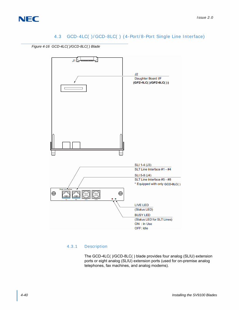
Issue 2.0
4-40 Installing the SV9100 Blades
4.3 GCD-4LC( )/GCD-8LC( ) (4-Port/8-Port Single Line Interface)
4.3.1 Description
The GCD-4LC( )/GCD-8LC( ) blade provides four analog (SLIU) extension ports or eight analog (SLIU) extension ports (used for on-premise analog telephones, fax machines, and analog modems).
Figure 4-16 GCD-4LC( )/GCD-8LC( ) Blade

Issue 2.0
SV9100 System Hardware Manual 4-41
The GCD-4LC( ) and GCD-8LC( ) are not rated for OPX use. A GCD-4DIOPB blade should be used instead (it supports the analog DID and single line telephone interface functions, such as Off-Premise Extensions).
One extension status LED
One blade status LEDs
Constant current type battery feeding (25mA / -28Vdc)
Feeding Polarity Reverse Ability
Connector for GCD-4LC( )/GCD-8LC( ) Daughter Board
Ring Generator (16Hz, 75Vrms, -10Vdc)
Caller ID Sending Ability
Message Wait Lamp Ability (-110Vdc)
The GCD-8LC( ) consumes eight ports ranging between ports 1~896. The J3 and J4 connectors each provide connection to four analog station ports. The Jx connectors are not polarity sensitive.
Refer to the following tables for maximum upgrade capacities of the GCD-4LC( )/GCD-8LC( ) SLIU blades:
Table 2-6 SV9100 Maximum 9.5” Gateway and 19” System Capacities – Blades on page 2-12
Table 2-7 SV9100 Maximum 9.5” Base and Expansion System Capacities – Blades on page 2-14
4.3.2 Installation
Install the GCD-4LC( )/GCD-8LC( ) blade in any available universal slot.
If the GCD-4LC( )/GCD-8LC( ) is used, install it prior to inserting the GCD-8LC( ) into the chassis.
CAUTION
When connecting a fax machine or analog modem, make sure to set Program 15-03-03 to 1 (special terminal) to avoid communication problems.
The GCD-4LC( )/GCD-8LC( ) blade and the GPZ-4LC( )/GPZ-8LC( ) daughter board are categorized as TNV2. With this designation, off-premise wiring is not acceptable. Any cabling to these blades or daughter boards must be in the building – no outside cabling is permitted.
Branch connection is not acceptable.

Issue 2.0
4-42 Installing the SV9100 Blades
4.3.3 LED Indications
LED indications for the GCD-4LC( )/GCD-8LC( ) are listed in Table 4-16 GCD-4LC( )/GCD-8LC( ) LED Indications. Each LED is listed with its associated function and LED and Operational status.
Refer to Figure 4-16 GCD-4LC( )/GCD-8LC( ) Blade on page 4-40 for the location of the LEDs on the blades.
4.3.4 Connectors
Table 4-17 GCD-4LC( )/GCD-8LC( ) RJ-61 Cable Connector Pin-Outs on page 4-43 show the pin-outs for the RJ-61 connector. Figure 4-16 GCD-4LC( )/GCD-8LC( ) Blade on page 4-40 shows the location of the connectors and the pin number locations on the GCD-4LC( )/GCD-8LC( ) blades.
Table 4-16 GCD-4LC( )/GCD-8LC( ) LED Indications
LED Indication
Operation Status RemarksLive LED (Green)
Busy LED (Red)
On On System Initializing –
Flash (1s) On The assignment of the unit is refused.
When you exceed the system capacity.When the main software version is not matched.
Flash (1s) Trouble found during self-diagnostics. –
Flash (100ms)
OnNormal
Operation
A Channel is busy (use another from CH1 ~ CHx).
–
Off All channels are idle. –
Off
OnUnit Busy
A Channel is busy (use another from CH1 ~ CHx).
–
Off All channels are idle. –
Flash 100ms (On/Off)
Downloading firmware. –

Issue 2.0
SV9100 System Hardware Manual 4-43
Table 4-17 GCD-4LC( )/GCD-8LC( ) RJ-61 Cable Connector Pin-Outs
RJ-61 Cable Connector GCD-4LCF – J3 (ports 1~4)
GCD-8LCF – J3 (ports 1~4), J4 (ports 5~8)
Pin No. Connection
1 T4 (Tip for port 4)
2 T3 (Tip for port 3)
3 T2 (Tip for port 2)
4 R1 (Ring for port 1)
5 T1 (Tip for port 1)
6 R2 (Ring for port 2
7 R3 (Ring for port 3)
8 R4 (Ring for port 4)

Issue 2.0
4-44 Installing the SV9100 Blades
4.4 GPZ-4LC( )/GPZ-8LC( ) (4-Port/8-Port SLI Daughter Board)
4.4.1 Description
The GPZ-4LC( ) and GPZ-8LC( ) daughter boards are mounted on the GCD-4LC( )/GCD-8LC( ). These boards provide:
4-Port Single Line and 8-Port Single Line analog extension ports (used for on-premise analog telephones, fax machines, and analog modems).
The GCD-4LC( )/GCD-8LC( ) is not rated for OPX use. A GCD-4DIOPB blade should be used instead (it supports the analog DID and single line telephone interface functions, such as Off-Premise Extensions).
Connector for GCD-4LC( )/GCD-8LC( ) Blades
Ring Generator
Caller ID Sending Ability
Message Wait Lamp Ability
Constant current type battery feeding (25mA / -28Vdc)
Feeding Polarity Reverse Ability
Figure 4-17 Installing the GPZ-4LC( )/GPZ-8LC( ) Daughter Board

Issue 2.0
SV9100 System Hardware Manual 4-45
Each J3 (GPZ-4LC( )/GPZ-8LC( )) or J4 (GPZ-8LC( ) only) connector provides connection to four analog station ports and is not polarity sensitive. The GPZ-8LC( ) consumes eight ports ranging between ports 1~896 (remember that the GCD-8LC( ) consumes eight ports).
Refer to the following tables for maximum upgrade capacity of the GPZ-4LC( )/GPZ-8LC( ) SLI daughter board:
Table 2-6 SV9100 Maximum 9.5” Gateway and 19” System Capacities – Blades on page 2-12
Table 2-7 SV9100 Maximum 9.5” Base and Expansion System Capacities – Blades on page 2-14
4.4.2 Installation
This daughter board can be installed on the GCD-4LC( ) or GCD-8LC( ) blade.
To install the GPZ-4LC( )/GPZ-8LC( ):
1. Four plastic spacers are Included with the GPZ-4LC( )/GPZ-8LC( ). Install the plastic spacers on either the GCD-4LC( )/GCD-8LC( ). Make sure to attach the spacers so that they extend out on the side of the daughter board which has the CN1 connector. Refer to Figure 4-17 Installing the GPZ-4LC( )/GPZ-8LC( ) Daughter Board on page 4-44.
2. Position the GPZ-4LC( )/GPZ-8LC( ) J1 connector over the J2 connector on the GCD-4LC( )/GCD-8LC( ) blade. Press the blade and board together, ensuring the plastic spacers lock in place. Refer to Figure 4-17 Installing the GPZ-4LC( )/GPZ-8LC( ) Daughter Board on page 4-44.
3. Install the GCD-4LC( )/GCD-8LC( ) blade in the slot in the chassis.
4.4.3 Connectors
Table 4-18 GPZ-4LC( )/GPZ-8LC( ) RJ-61 Cable Connector Pin-Outs on page 4-46 show the pin-outs for the RJ-61 connector. Figure 4-17 Installing the GPZ-4LC( )/GPZ-8LC( ) Daughter Board on page 4-44 shows the location of the connectors on the GPZ-4LC( )/GPZ-8LC( ) daughter boards.
CAUTION
When connecting a fax machine or analog modem, make sure to set Program 15-03-03 to 1 (special terminal) to avoid communication problems.
The GCD-4LC( )/GCD-8LC( ) blade and the GPZ-4LC( )/GPZ-8LC( ) daughter board are categorized as TNV2. With this designation, off-premise wiring is not acceptable. Any cabling to these blades or daughter boards must be in the building – no outside cabling is permitted.
Branch connection is not acceptable.

Issue 2.0
4-46 Installing the SV9100 Blades
Table 4-18 GPZ-4LC( )/GPZ-8LC( ) RJ-61 Cable Connector Pin-Outs
RJ-61 Cable Connector – GPZ-4LCF – J3 (ports 9~12)
GPZ-8LCF – J3 (ports 9~12), J4 (ports 13~16)
Pin No. Connection
1 T4 (Tip for port 4)
2 T3 (Tip for port 3)
3 T2 (Tip for port 2)
4 R1 (Ring for port 1)
5 T1 (Tip for port 1)
6 R2 (Ring for port 2)
7 R3 (Ring for port 3)
8 R4 (Ring for port 4)
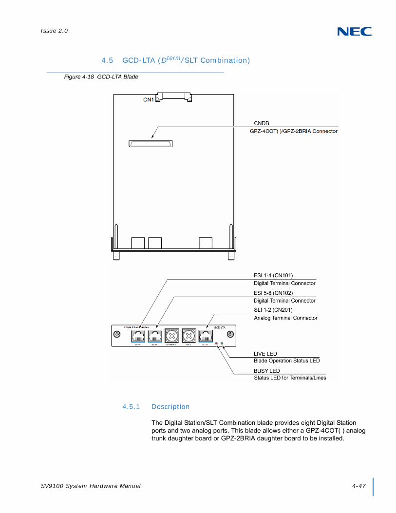
Issue 2.0
SV9100 System Hardware Manual 4-47
4.5 GCD-LTA (Dterm/SLT Combination)
4.5.1 Description
The Digital Station/SLT Combination blade provides eight Digital Station ports and two analog ports. This blade allows either a GPZ-4COT( ) analog trunk daughter board or GPZ-2BRIA daughter board to be installed.
Figure 4-18 GCD-LTA Blade

Issue 2.0
4-48 Installing the SV9100 Blades
The blade provides:
Eight Digital Station ports
Two analog extension ports support Caller ID Circuit, Message Waiting Lamp Control (Controlling Voltage:-110Vdc) for all ports
Two status LEDs
Refer to the following tables for maximum upgrade capacities of the GCD-LTA blade:
Table 2-6 SV9100 Maximum 9.5” Gateway and 19” System Capacities – Blades on page 2-12
Table 2-7 SV9100 Maximum 9.5” Base and Expansion System Capacities – Blades on page 2-14
4.5.2 Installation
Install the GCD-LTA blade in any available universal slot.
CAUTION
When connecting a fax machine or analog modem, make sure to set Program 15-03-03 to 1 (special terminal) to avoid communication problems.
The GCD-LTA is categorized as TNV2. With this designation, off-premise wiring is not acceptable.
Branch connection is not acceptable.

Issue 2.0
SV9100 System Hardware Manual 4-49
4.5.3 LED Indications
LED indications for the GCD-LTA are indicated in Table 4-19 GCD-LTA LED Indications. Each LED is listed with its associated function and LED and Operational status. Refer to Figure 4-18 GCD-LTA Blade on page 4-47 for the location of the LEDs on the blade.
Table 4-19 GCD-LTA LED Indications
LED Indication
Operation Status RemarksLive LED (Green)
Busy LED (Red)
On On System Initializing –
Flash (1s) On The assignment of the unit is refused.
When you exceed the system capacity.When the main software version is not matched.
Flash (1s) Trouble found during self-diagnostics. –
Flash (100ms)
OnNormal
Operation
A Channel is busy (use another from CH1 ~ CHx).
–
Off All channels are idle. –
Off
OnUnit Busy
A Channel is busy (use another from CH1 ~ CHx).
–
Off All channels are idle. –
Flash 80ms (On/Off) x 3/400ms
Off
Downloading firmware. –

Issue 2.0
4-50 Installing the SV9100 Blades
4.5.4 Connectors
Table 4-20 GCD-LTA RJ11 Cable Connector Pin-Outs shows the pin-outs for the RJ-61 connector. Refer to Figure 4-18 GCD-LTA Blade on page 4-47 for an illustration showing the location of the connectors on the GCD-LTA blade.
Table 4-20 GCD-LTA RJ11 Cable Connector Pin-Outs
RJ11 Cable Connector DLCA: CN101 (ports 1~4)DLCA: CN102 (ports 5~8)
Pin No. Connection
1 T4/T8 (Tip for port 4 or 8)
2 T3/T7 (Tip for port 3 or 7)
3 T2/T6 (Tip for port 2 or 6)
4 R1/R5 (Ring for port 1 or 5)
5 T1/T5 (Tip for port 1 or 5)
6 R2/R6 (Ring for port 2 or 6)
7 R3/R7 (Ring for port 3 or 7)
8 R4/R8 (Ring for port 4 or 8)
RJ11 Cable Connector LCA: CN201 (ports 1~2)
Pin No. Connection
1 –
2 –
3 T2 (Tip for port 2)
4 R1 (Ring for port 1)
5 T1 (Tip for port 1)
6 R2 (Ring for port 2)
7 –
8 –

Issue 2.0
SV9100 System Hardware Manual 4-51
SECTION 5 TRUNK BLADES
5.1 GCD-4COT( ) (4 Loop and Ground Start Interface)
Figure 4-19 GCD-4COT( ) Blade
Issue 2.0
4-52 Installing the SV9100 Blades
5.1.1 Description
The GCD-4COT( ) blade provides:
GCD-4COT( ): Four analog loop start/ground start trunk circuits
One trunk status LED
One Blade status LED
Four Caller ID Circuits
Two Power Failure Transfer Circuits
Connection for GPZ-COT( ) Daughter Board
The GCD-4COT( ) blade consumes four trunk ports ranging between ports 001~400. The CN2 connector provides connection to four analog trunk ports, which are polarity sensitive (tip-to-tip, ring-to-ring). The power failure circuits (CN3), however, are not polarity sensitive.
Refer to the following tables for maximum upgrade capacities of the GCD-4COT( ) blade:
Table 2-6 SV9100 Maximum 9.5” Gateway and 19” System Capacities – Blades on page 2-12
Table 2-7 SV9100 Maximum 9.5” Base and Expansion System Capacities – Blades on page 2-14
5.1.2 Installation
Install the GCD-4COT( ) blade into an available slot in the chassis. (Refer to Figure 4-19 GCD-4COT( ) Blade on page 4-51 for a layout of the blade.)
If the GPZ-COT( ) is to be used, install this prior to inserting the GCD-4COT( ) blade into the chassis.
CAUTION
When using the GCD-4COT( ) blade for ground start trunks, the PBX ground must be connected as described in Chapter 3, section 3.3.3 Install Grounding on 19” Chassis on page 3-19 for the trunks to function correctly.
The trunk ports are polarity sensitive. Be careful when wiring the trunks.
When connecting the RJ-61 cables to the GCD-4COT( ) blades, note the position of the Power Failure connector (CN3). Do not confuse this connector as the trunk connector (CN2).
Switching from Loop Start to Ground Start is set in system programming.
Do not wire an RJ-11 directly to the GCD-4COT( ) interface. Use the appropriate RJ-61 wiring when connecting to the GCD-4COT( ).

Issue 2.0
SV9100 System Hardware Manual 4-53
5.1.3 LED Indications
LED indications for the GCD-4COT( ) are listed in Table 4-21 GCD-4COT( ) LED Indications. Each LED is listed with its associated function and LED and Operational status.
Refer to Figure 4-19 GCD-4COT( ) Blade on page 4-51 for the location of the LEDs on the blades.
5.1.4 Connectors
Table 4-22 GCD-4COT( ) RJ-61 Cable Connector Pin-Outs on page 4-54 shows the pin-outs for the RJ-61 connector. Refer to Figure 4-19 GCD-4COT( ) Blade on page 4-51 for an illustration showing the location of the connectors on the GCD-4COT( ) blades.
Table 4-21 GCD-4COT( ) LED Indications
LED Indication
Operation Status RemarksLive LED (Green)
Busy LED (Red)
On On System Initializing –
Flash (1s) On The assignment of the unit is refused.
When you exceed the system capacity.When the main software version is not matched.
Flash (1s) Trouble found during self-diagnostics. –
Flash (100ms)
OnNormal
Operation
A Channel is busy (use another from CH1 ~ CHx).
–
Off All channels are idle. –
Off
OnUnit Busy
A Channel is busy (use another from CH1 ~ CHx).
–
Off All channels are idle. –
Flash 80ms (On/Off) x 3/400ms
Off
Downloading firmware. –

Issue 2.0
4-54 Installing the SV9100 Blades
Table 4-22 GCD-4COT( ) RJ-61 Cable Connector Pin-Outs
RJ-61 Cable Connector – CN2, TrunksThe CN2 connector is polarity sensitive (tip-to-tip, ring-to-ring)
Pin No. Connection
1 Circuit 4 – Tip
2 Circuit 3 – Tip
3 Circuit 2 – Tip
4 Circuit 1 – Ring
5 Circuit 1 – Tip
6 Circuit 2 – Ring
7 Circuit 3 – Ring
8 Circuit 4 – Ring
RJ-61 Cable Connector – CN3, SLT Interface for Power Failure
Pin No. Connection
1 –
2 –
3 Circuit 2 – Tip
4 Circuit 1 – Ring
5 Circuit 1 – Tip
6 Circuit 2 – Ring
7 –
8 –

Issue 2.0
SV9100 System Hardware Manual 4-55
5.2 GPZ-4COT( ) (4 Loop and Ground Start Interface Daughter Board)
5.2.1 Description
The GPZ-4COT( ) daughter board provides:
Four analog loop start/ground start trunk circuits
Four Caller ID Circuits
Connector for GCD-4COT( ) Blade
Connector for GCD-LTA
The GPZ-4COT( ) consumes four trunk ports ranging between ports 001~400. The CN2 connector provides connection to four analog trunk ports, which are polarity sensitive (tip-to-tip, ring-to-ring). The power failure circuits (CN3), however, are not polarity sensitive.
Figure 4-20 Installing the GPZ-4COT( ) Daughter Board

Issue 2.0
4-56 Installing the SV9100 Blades
Refer to the following tables for maximum upgrade capacities of the GPZ-4COT( ) COI daughter board:
Table 2-6 SV9100 Maximum 9.5” Gateway and 19” System Capacities – Blades on page 2-12
Table 2-7 SV9100 Maximum 9.5” Base and Expansion System Capacities – Blades on page 2-14
5.2.2 Installation
To install the GPZ-4COT( ):
1. Four spacers are included with the GPZ-4COT( ). Install the plastic spacers on the GCD-4COT( ) or GCD-LTA blade. Make sure to attach the spacers so that they extend out on the side of the daughter board which has the CN1 connector.
2. Position the GPZ-4COT( ) CN1 connector over the CN4 connector on the GCD-4COT( ) or GCD-LTA. Press the blade and board together, ensuring the plastic spacers lock in place.
3. Install the GPZ-4COTE blade (refer to Figure 4-20 Installing the GPZ-4COT( ) Daughter Board on page 4-55).
5.2.3 Connectors
Table 4-23 GPZ-4COT( ) RJ-61 Cable Connector Pin-Outs on page 4-57 shows the pin-outs for the RJ-61 connector. Figure 4-20 Installing the GPZ-4COT( ) Daughter Board on page 4-55 shows the location of the connectors on the GPZ-4COT( ) daughter board.
CAUTION
When using the GPZ-4COT( ) daughter board for ground start trunks, the PBX ground must be connected as described in Chapter 3, section 3.3.3 Install Grounding on 19” Chassis on page 3-19 for the trunks to function correctly.
The trunk ports are polarity sensitive. Be careful when wiring the trunks.
When connecting the RJ-61 cable to the GPZ-4COT( ) daughter board, note the position of the Power Failure connector (CN3). Do not confuse this connector as the trunk connector (CN2).
Switching from Loop Start to Ground Start is set in system programming.
Do not wire an RJ-11 directly to the GCD-4COT( ) interface. Use the appropriate RJ-61 wiring when connecting to the GCD-4COT( ).

Issue 2.0
SV9100 System Hardware Manual 4-57
Table 4-23 GPZ-4COT( ) RJ-61 Cable Connector Pin-Outs
RJ-61 Cable ConnectorCN2, Trunks – Connecting to GCD-4COT( ) Blade
The CN2 connector is polarity sensitive (tip-to-tip, ring-to-ring)
Pin No. Connection
1 Circuit 8 – Tip
2 Circuit 7 – Tip
3 Circuit 6 – Tip
4 Circuit 5 – Ring
5 Circuit 5 – Tip
6 Circuit 6 – Ring
7 Circuit 7 – Ring
8 Circuit 8 – Ring
RJ-61 Cable ConnectorCN2, Trunks – Connecting to GCD-LTA Blade
The CN2 connector is polarity sensitive (tip-to-tip, ring-to-ring)
Pin No. Connection
1 Circuit 4 – Tip
2 Circuit 3 – Tip
3 Circuit 2 – Tip
4 Circuit 1 – Ring
5 Circuit 1 – Tip
6 Circuit 2 – Ring
7 Circuit 3 – Ring
8 Circuit 4 – Ring

Issue 2.0
4-58 Installing the SV9100 Blades
5.3 GCD-2BRIA (2 Basic Rate Interface)
5.3.1 Description
This unit is an interface unit that accommodates an ISDN (Basic Rate) circuit.
Figure 4-21 GCD-2BRIA Blade

Issue 2.0
SV9100 System Hardware Manual 4-59
The BRI blade provides:
Two (GCD-2BRIA) 2-Channel Circuits (2B + D) configured as T-Bus
64Kb/s Clear B-Channel and 16Kb/s D-Channel
Two Status LEDs
Connector for GPZ-2BRIA
These trunk circuits can be connected to either ISDN trunks or ISDN telephones, depending on the switch setting in system programming. All ISDN telephone circuits (#1-2 and #3-4 with the BRI daughter board) are supplied DC power from the system.
The BRI Interface blade uses a single universal slot. Each blade connects to the network via an NTI Network Termination.
To block new calls on the blade, system programming must be used. This program prevents new calls from being established on the blade, but it does not terminate any existing call.
With the maximum number of blades installed, the following can be provided:
The 2BRI provides 30 BRI circuits and 60 BRI channels. (Port Consumption: T-Bus=4 ports)
Refer to the following tables for maximum upgrade capacities of the GCD-2BRIA blade:
Table 2-6 SV9100 Maximum 9.5” Gateway and 19” System Capacities – Blades on page 2-12
Table 2-7 SV9100 Maximum 9.5” Base and Expansion System Capacities – Blades on page 2-14
5.3.2 Installation
To install the GCD-2BRIA:
1. Plug the GCD-2BRIA blade into the system chassis.
2. Before proceeding to Step 3, wait to verify that the STATUS LED starts to flash. (Refer to Figure 4-21 GCD-2BRIA Blade on page 4-58 for the location of the LEDs on the blade.)
NOTE
With normal operation, the status LED flashes fast. If trouble was found during the self diagnostics routine, the status LED flashes slow.
Once connected, the PKG LED will not be indicated for the status of Layer 1 Link.
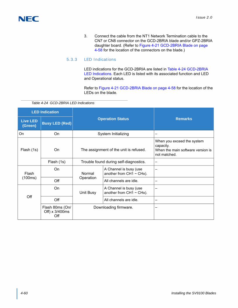
Issue 2.0
4-60 Installing the SV9100 Blades
3. Connect the cable from the NT1 Network Termination cable to the CN7 or CN8 connector on the GCD-2BRIA blade and/or GPZ-2BRIA daughter board. (Refer to Figure 4-21 GCD-2BRIA Blade on page 4-58 for the location of the connectors on the blade.)
5.3.3 LED Indications
LED indications for the GCD-2BRIA are listed in Table 4-24 GCD-2BRIA LED Indications. Each LED is listed with its associated function and LED and Operational status.
Refer to Figure 4-21 GCD-2BRIA Blade on page 4-58 for the location of the LEDs on the blade.
Table 4-24 GCD-2BRIA LED Indications
LED Indication
Operation Status RemarksLive LED (Green)
Busy LED (Red)
On On System Initializing –
Flash (1s) On The assignment of the unit is refused.
When you exceed the system capacity.When the main software version is not matched.
Flash (1s) Trouble found during self-diagnostics. –
Flash (100ms)
OnNormal
Operation
A Channel is busy (use another from CH1 ~ CHx).
–
Off All channels are idle. –
Off
OnUnit Busy
A Channel is busy (use another from CH1 ~ CHx).
–
Off All channels are idle. –
Flash 80ms (On/Off) x 3/400ms
Off
Downloading firmware. –

Issue 2.0
SV9100 System Hardware Manual 4-61
5.3.4 Connectors
Table 4-25 GCD-2BRIA RJ-61 Cable Connector Pin-Outs show the pin-outs for the RJ-61 cable connector for T-Bus connections. Figure 4-21 GCD-2BRIA Blade on page 4-58 shows the location of the connectors on the GCD-2BRIA blade.
Table 4-25 GCD-2BRIA RJ-61 Cable Connector Pin-Outs
RJ-61 Cable Connector – CN7, CN8T-Bus Connection
Pin No. Connection
1 —
2 —
3 TA
4 RA
5 RB
6 TB
7 —
8 —

Issue 2.0
4-62 Installing the SV9100 Blades
5.4 GPZ-2BRIA (2 Basic Rate Interface Daughter Board)
5.4.1 Description
This daughter board provides two BRI circuits and is installed on the GCD-2BRIA blade. This board provides:
Two (GCD-2BRIA) 2-Channel Circuits (2B + D) configured as T-Bus
64Kb/s Clear B-Channel and 16Kb/s D-Channel
Connection point for GCD-2BRIA
Connection point for GCD-LTA
These trunk circuits can be connected to ISDN trunks or ISDN telephones, depending on the switch setting in system programming. All ISDN telephone circuits [#1-2 (BRI blade) and #3-4 (with the BRI daughter board)] are supplied DC power from the UNIVERGE SV9100 system.
System programming must be used to block new calls on the blade. This program prevents new calls from being established on the blade, but does not terminate any existing call.
Figure 4-22 Installing the GPZ-2BRIA Daughter Board

Issue 2.0
SV9100 System Hardware Manual 4-63
Refer to the following tables for maximum upgrade capacities of the GPZ-2BRIA daughter board:
Table 2-6 SV9100 Maximum 9.5” Gateway and 19” System Capacities – Blades on page 2-12
Table 2-7 SV9100 Maximum 9.5” Base and Expansion System Capacities – Blades on page 2-14
5.4.2 Installation
To install the GPZ-2BRIA on the GCD-2BRIA:
Attach the GPZ-2BRIA daughter board to the GCD-2BRIA blade by lining up the CN5 connectors and pressing the boards together. (Refer to Figure 4-22 Installing the GPZ-2BRIA Daughter Board on page 4-62.)
1. Install the GCD-2BRIA blade into the system chassis.
2. Before proceeding to Step 3, wait to verify that the STATUS LED starts to flash.
Connect the cable from the NT1 Network Termination cable to the CN7 or CN8 connector on the GCD-2BRIA and/or GPZ-2BRIA daughter board.
5.4.3 Connectors
Table 4-26 GPZ-2BRIA RJ-61 Cable Connector Pin-Outs on page 4-64 shows the pin-outs for the RJ-61 cable connector for T-Bus connections. Figure 4-22 Installing the GPZ-2BRIA Daughter Board on page 4-62 shows the location of the connectors on the GPZ-2BRIA daughter board.
NOTE
With normal operation, the status LED flashes fast. If trouble was found during the self diagnostics routine, the status LED flashes slow.
Once connected, the PKG LED is not indicated for the status of Layer 1 Link.

Issue 2.0
4-64 Installing the SV9100 Blades
Table 4-26 GPZ-2BRIA RJ-61 Cable Connector Pin-Outs
RJ-61 Cable Connector – CN7, CN8T-Bus Connection
Pin No. Connection
1 —
2 —
3 TA
4 RA
5 RB
6 TB
7 —
8 —

Issue 2.0
SV9100 System Hardware Manual 4-65
5.5 GCD-4DIOPB (DID/OPX Interface)
5.5.1 Description
The GCD-4DIOPB supports the analog DID and single line telephone interface functions (such as Off-Premise Extension). The function type is assigned in programming for each port. The circuit types, however, should be grouped together. For example, with three DID circuits and one OPX circuit, they should be grouped as DID, DID, DID and OPX and not DID, DID, OPX and DID.
Figure 4-23 GCD-4DIOPB Blade

Issue 2.0
4-66 Installing the SV9100 Blades
The GCD-4DIOPB provides:
Four (DIOPA) DID trunk circuits or four OPX circuits
Two Blade status LEDs
-48VDC
Refer to the following tables for maximum upgrade capacities of the GCD-4DIOPB blade:
Table 2-6 SV9100 Maximum 9.5” Gateway and 19” System Capacities – Blades on page 2-12
Table 2-7 SV9100 Maximum 9.5” Base and Expansion System Capacities – Blades on page 2-14
5.5.2 Installation
The GCD-4DIOPB can be installed in any universal slot.
5.5.3 LED Indications
LED indications for the GCD-4DIOPB are listed in Table 4-27 GCD-4DIOPB LED Indications. Each LED is listed with its associated function and LED and Operational status.
Refer to Figure 4-23 GCD-4DIOPB Blade on page 4-65 for the location of the LEDs on the blade.
Table 4-27 GCD-4DIOPB LED Indications
LED Indication
Operation Status RemarksLive LED (Green)
Busy LED (Red)
On On System Initializing –
Flash (1s) On The assignment of the unit is refused.
When you exceed the system capacity.When the main software version is not matched.
Flash (1s) Trouble found during self-diagnostics. –
Flash (100ms)
OnNormal
Operation
A Channel is busy (use another from CH1 ~ CHx).
–
Off All channels are idle. –
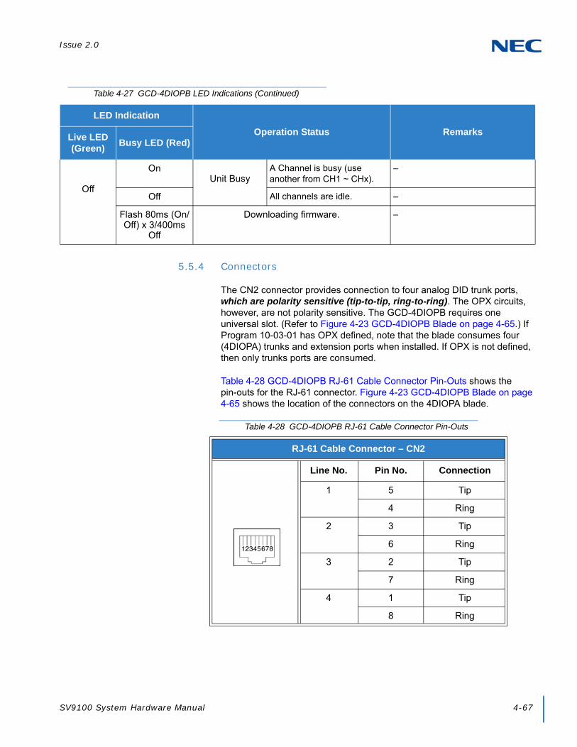
Issue 2.0
SV9100 System Hardware Manual 4-67
5.5.4 Connectors
The CN2 connector provides connection to four analog DID trunk ports, which are polarity sensitive (tip-to-tip, ring-to-ring). The OPX circuits, however, are not polarity sensitive. The GCD-4DIOPB requires one universal slot. (Refer to Figure 4-23 GCD-4DIOPB Blade on page 4-65.) If Program 10-03-01 has OPX defined, note that the blade consumes four (4DIOPA) trunks and extension ports when installed. If OPX is not defined, then only trunks ports are consumed.
Table 4-28 GCD-4DIOPB RJ-61 Cable Connector Pin-Outs shows the pin-outs for the RJ-61 connector. Figure 4-23 GCD-4DIOPB Blade on page 4-65 shows the location of the connectors on the 4DIOPA blade.
Off
OnUnit Busy
A Channel is busy (use another from CH1 ~ CHx).
–
Off All channels are idle. –
Flash 80ms (On/Off) x 3/400ms
Off
Downloading firmware. –
Table 4-27 GCD-4DIOPB LED Indications (Continued)
LED Indication
Operation Status RemarksLive LED (Green)
Busy LED (Red)
Table 4-28 GCD-4DIOPB RJ-61 Cable Connector Pin-Outs
RJ-61 Cable Connector – CN2
Line No. Pin No. Connection
1 5 Tip
4 Ring
2 3 Tip
6 Ring
3 2 Tip
7 Ring
4 1 Tip
8 Ring
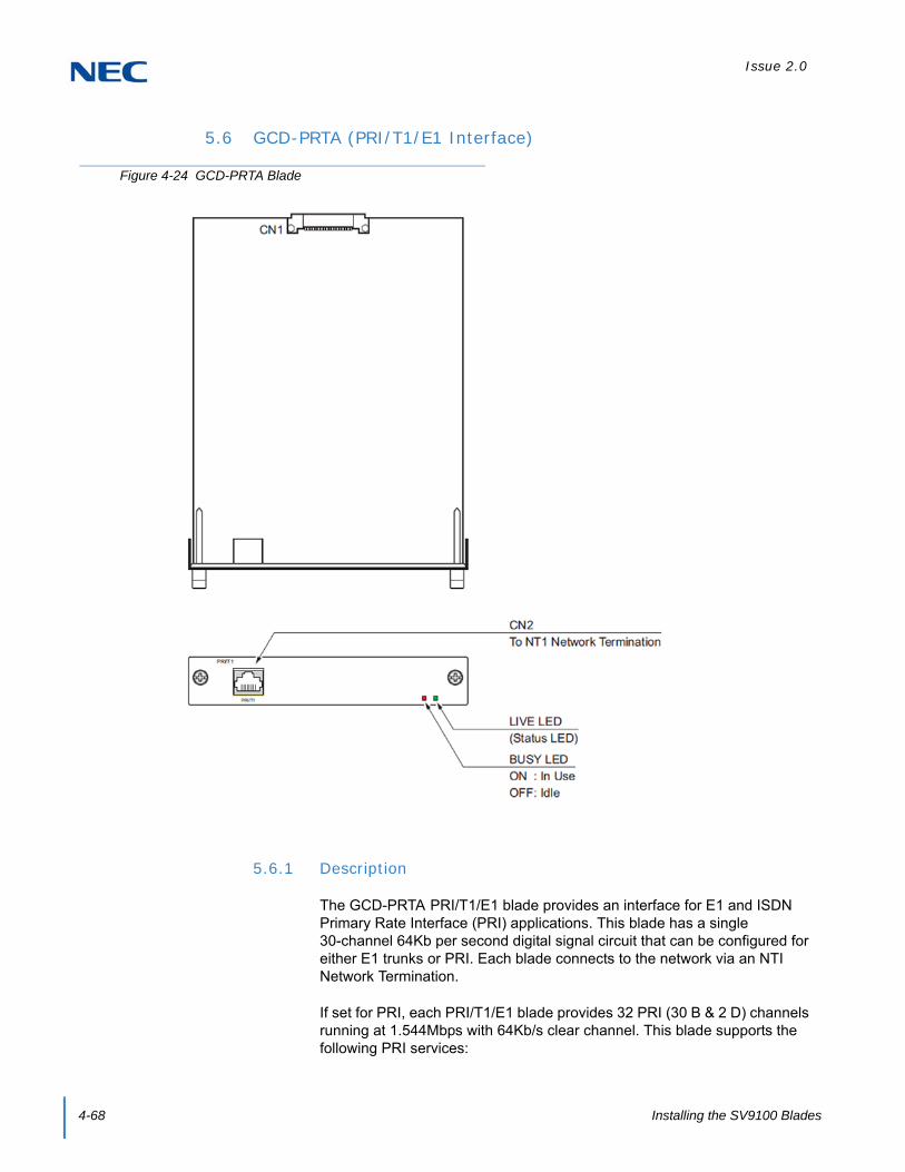
Issue 2.0
4-68 Installing the SV9100 Blades
5.6 GCD-PRTA (PRI/T1/E1 Interface)
5.6.1 Description
The GCD-PRTA PRI/T1/E1 blade provides an interface for E1 and ISDN Primary Rate Interface (PRI) applications. This blade has a single 30-channel 64Kb per second digital signal circuit that can be configured for either E1 trunks or PRI. Each blade connects to the network via an NTI Network Termination.
If set for PRI, each PRI/T1/E1 blade provides 32 PRI (30 B & 2 D) channels running at 1.544Mbps with 64Kb/s clear channel. This blade supports the following PRI services:
Figure 4-24 GCD-PRTA Blade

Issue 2.0
SV9100 System Hardware Manual 4-69
Basic PRI Call Control (BCC)
Display of incoming caller’s name and number (when allowed by the telco)
Speech and 3.1 KHz audio
When installed, GCD-PRTA uses the first block of 30 consecutive trunk ports. For example, if a COIU blade is installed for trunks 1~8, the GCD-PRTA automatically uses trunks 9~32. If the COIU blades are installed for trunks 1~8 and 17~24, GCD-PRTA uses trunks 25~56. The GCD-PRTA cannot use trunks 9~16 (even if available) since they are not part of a consecutive block of 32 trunks. Each GCD-PRTA requires 32 ports in the system, even if not all the ports are used, otherwise the blade does not function.
The GCD-PRTA requires one universal slot.
Refer to the following tables for maximum upgrade capacities of the GCD-PRTA blade:
Table 2-6 SV9100 Maximum 9.5” Gateway and 19” System Capacities – Blades on page 2-12
Table 2-7 SV9100 Maximum 9.5” Base and Expansion System Capacities – Blades on page 2-14

Issue 2.0
4-70 Installing the SV9100 Blades
5.6.2 Installation
To install the GCD-PRTA:
1. Plug the GCD-PRTA into any universal slot in the chassis.
2. Use Program 10-51-01 (PRI/T1/E1) to set the GCD-PRTA blade to either PRI or T1 or E1.
3. Connect the cable from the NT1 Network Termination cable to the CN2 connector on the GCD-PRTA. Figure 4-25 PRI Layout for NT-1 Network is a cabling diagram.)
5.6.3 LED Indications
NOTE With normal operation, LED 1 flashes green.
NOTE
The NT1 connects to the network through an 8-pin RJ-45/RJ48C connector. Use either the RJ48C plug-to-RJ48C plug, which ships with the CSU or an RJ-45/48C plug-to RJ-45/48C plug straight through or CAT5 cable to connect the T1 to the CSU. (Refer to Table 4-32 GCD-PRTA RJ48C Connector Pin-outs on page 4-73.)
With PRI Networking, a crossover cable must be used on the master system PRI/T1/E1 blade or NT1to the telco demarcation. If the systems are networked side by side and not through telco, a straight-through cable is used.
Figure 4-25 PRI Layout for NT-1 Network

Issue 2.0
SV9100 System Hardware Manual 4-71
LED indications for the GCD-PRTA are listed in Table 4-29 GCD-PRTA LED Indications. Each LED is listed with its associated function and LED and Operational status.
Refer to Figure 4-24 GCD-PRTA Blade on page 4-68 for the location of the LEDs on the blade.
Table 4-29 GCD-PRTA LED Indications
LED Indication
Operation Status RemarksLive LED (Green)
Busy LED (Red)
On On System Initializing –
Flash (1s) On The assignment of the unit is refused.
When you exceed the system capacity.When the main software version is not matched.
Flash (1s) Trouble found during self-diagnostics. –
Flash (100ms)
OnNormal
Operation
A Channel is busy (use another from CH1 ~ CHx).
–
Off All channels are idle. –
Off
OnUnit Busy
A Channel is busy (use another from CH1 ~ CHx).
–
Off All channels are idle. –
Flash 80ms (On/Off) x 3/400ms
Off
Downloading firmware. –

Issue 2.0
4-72 Installing the SV9100 Blades
Refer to Figure 4-26 GCD-PRTA LED Indication Pattern of Layer 1 on T1 Unit for LED pattern information. LED indications for the T1 are listed in Table 4-30 T1 LED Indications.
Figure 4-26 GCD-PRTA LED Indication Pattern of Layer 1 on T1 Unit
Table 4-30 T1 LED Indications
Alarm Details of the Alarm LED Indication Pattern
LOS Loss of Signal (Red Alarm)No Signal (Analog Interface)
Following an alarm blink (red, green, red, green) a Red LED lights.
AIS Alarm Indication Signal(Blue Alarm)
Following an alarm blink (red, green, red, green) a Red LED slowly flashes On and Off twice.
OOF Out Of Frame (Red Alarm) Following an alarm blink (red, green, red, green) a Red LED and Green LED flash On and Off three times simultaneously.
RAI Remote Alarm Indication (Yellow Alarm)
Following an alarm blink (red, green, red, green) a Green LED flashes On and Off twice.
No Alarm The system does the LED control.
The order of priority is set up to alarm in the order LOSAISOOFRAI.
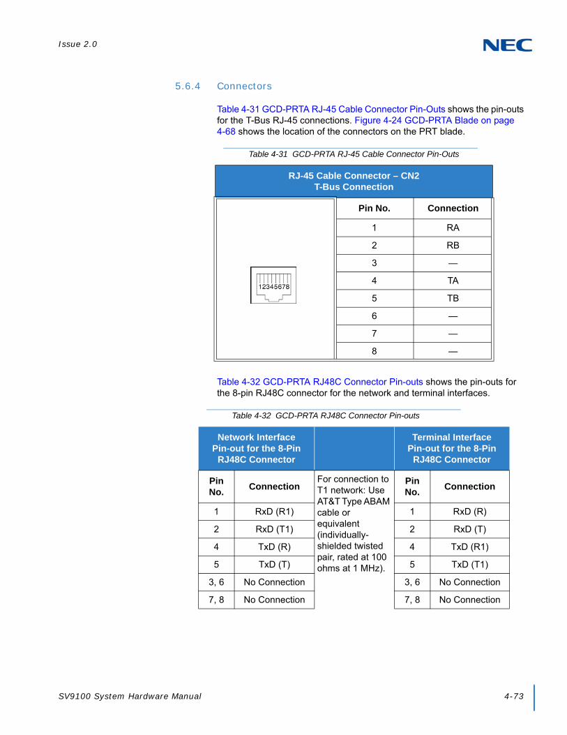
Issue 2.0
SV9100 System Hardware Manual 4-73
5.6.4 Connectors
Table 4-31 GCD-PRTA RJ-45 Cable Connector Pin-Outs shows the pin-outs for the T-Bus RJ-45 connections. Figure 4-24 GCD-PRTA Blade on page 4-68 shows the location of the connectors on the PRT blade.
Table 4-32 GCD-PRTA RJ48C Connector Pin-outs shows the pin-outs for the 8-pin RJ48C connector for the network and terminal interfaces.
Table 4-31 GCD-PRTA RJ-45 Cable Connector Pin-Outs
RJ-45 Cable Connector – CN2T-Bus Connection
Pin No. Connection
1 RA
2 RB
3 —
4 TA
5 TB
6 —
7 —
8 —
Table 4-32 GCD-PRTA RJ48C Connector Pin-outs
Network Interface Pin-out for the 8-Pin
RJ48C Connector
Terminal Interface Pin-out for the 8-Pin
RJ48C Connector
Pin No.
ConnectionFor connection to T1 network: Use AT&T Type ABAM cable or equivalent (individually-shielded twisted pair, rated at 100 ohms at 1 MHz).
Pin No.
Connection
1 RxD (R1) 1 RxD (R)
2 RxD (T1) 2 RxD (T)
4 TxD (R) 4 TxD (R1)
5 TxD (T) 5 TxD (T1)
3, 6 No Connection 3, 6 No Connection
7, 8 No Connection 7, 8 No Connection
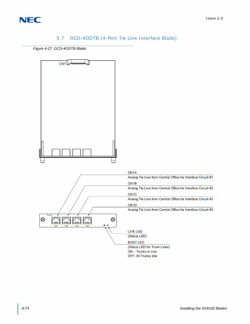
Issue 2.0
4-74 Installing the SV9100 Blades
5.7 GCD-4ODTB (4-Port Tie Line Interface Blade)
Figure 4-27 GCD-4ODTB Blade
Issue 2.0
SV9100 System Hardware Manual 4-75
5.7.1 Description
The GCD-4ODTB Tie Line blade is an out band dial type analog tie line interface blade. This blade supports system connections to either 2-wire (four lead, tip/ring) or 4-wire (six lead, tip/ring/tip 1/ring 1) E&M signaling tie lines (determined in Program 10-13). System programming is used also to select the connection types with Type I or Type V. The GCD-4ODTB consumes four ports ranging between ports 001~400 (SV9100). Each blade requires one universal slot and provides:
Four analog 4-circuit tie line interfaces
Two Blade status LEDs
Two straps and one switch per circuit to determine the circuit type
Refer to the following tables for maximum upgrade capacities of the GCD-4ODTB blade:
Table 2-6 SV9100 Maximum 9.5” Gateway and 19” System Capacities – Blades on page 2-12
Table 2-7 SV9100 Maximum 9.5” Base and Expansion System Capacities – Blades on page 2-14
5.7.2 Installation
1. Set the straps for either the 2-wire or 4-wire. Refer to Figure 4-27 GCD-4ODTB Blade on page 4-74.
2. Install the GCD-4ODTB into a slot in the chassis.
TIP
Limitation depends on the connecting Router, Multiplexer or Exchange. If the UNIVERGE SV9100 is connected to another UNIVERGE SV9100 directly, there is up to 1,500 ohms loop resistance (including system).
CAUTION
When a router or multiplexer is connected instead of a trunk, the SG terminal of the router or multiplexer must be connected to the FG grounding terminal on the UNIVERGE SV9100 chassis. When a tie line trunk is connected, the FG terminal must be connected to the ground. If the FG terminal is not connected correctly, the signal may fail.
When tie lines are connected to the system, be careful of the Tip and Ring polarity.

Issue 2.0
4-76 Installing the SV9100 Blades
5.7.3 LED Indications
LED indications for the GCD-4ODTB are listed in Table 4-33 GCD-4ODTB LED Indications. Each LED is listed with its associated function and LED and Operational status.
Refer to Figure 4-27 GCD-4ODTB Blade on page 4-74 for the location of the LEDs on the blade.
5.7.4 Connectors
Table 4-34 GCD-4ODTB RJ-61 Cable Connector Pin-Outs on page 4-77 shows the pin-outs for the RJ-61 connector. Figure 4-27 GCD-4ODTB Blade on page 4-74 shows the location of the connectors on the ODT blade.
Table 4-33 GCD-4ODTB LED Indications
LED Indication
Operation Status RemarksLive LED (Green)
Busy LED (Red)
On On System Initializing –
Flash (1s) On The assignment of the unit is refused.
When you exceed the system capacity.When the main software version is not matched.
Flash (1s) Trouble found during self-diagnostics. –
Flash (100ms)
OnNormal
Operation
A Channel is busy (use another from CH1 ~ CHx).
–
Off All channels are idle. –
Off
OnUnit Busy
A Channel is busy (use another from CH1 ~ CHx).
–
Off All channels are idle. –
Flash 80ms (On/Off) x 3/400ms
Off
Downloading firmware. –

Issue 2.0
SV9100 System Hardware Manual 4-77
Table 4-34 GCD-4ODTB RJ-61 Cable Connector Pin-Outs
RJ-61 Cable Connector – 2-Wire E&M, CN1A~CN1D
Pin No. Connection Description
1 — Not Used
2 M Control signal to trunk
3 — Not Used
4 R Voice signal both ways
5 T Voice signal both ways
6 — Not Used
7 E Control signal from trunk
8 — Not Used
RJ-61 Cable Connector – 4-Wire E&M, CN100~CN400
Pin No. Connection Description
1 — Not Used
2 M Control signal to trunk
3 R Voice signal to trunk
4 R1 Voice signal from trunk
5 T1 Voice signal from trunk
6 T Voice signal to trunk
7 E Control signal from trunk
8 — Not Used
Using Type I or Type V, a system loopback test can be performed by connecting E&M1 to E&M2.
<2-Wire E&M> <4-Wire E&M>
E&M1E
M R T
E&M2 M E T R
E&M1E
M R T
R1 T1
E&M2 M E T1 R1 T R
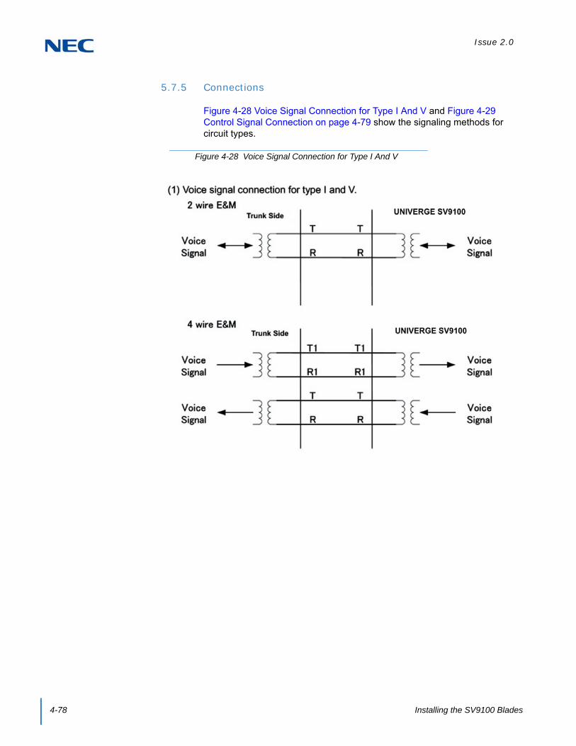
Issue 2.0
4-78 Installing the SV9100 Blades
5.7.5 Connections
Figure 4-28 Voice Signal Connection for Type I And V and Figure 4-29 Control Signal Connection on page 4-79 show the signaling methods for circuit types.
Figure 4-28 Voice Signal Connection for Type I And V

Issue 2.0
SV9100 System Hardware Manual 4-79
Figure 4-29 Control Signal Connection

Issue 2.0
4-80 Installing the SV9100 Blades
SECTION 6 OPTIONAL BLADES
6.1 GCD-VM00 (Voice Mail and Server)
6.1.1 Description
This blade is a PC platform installed in the UNIVERGE SV9100 that contains data storage for voice recording and application software supporting a maximum of 16 ports.
A digital signal processor/voice processing section handles the following functions:
DTMF detection
DTMF generation
General tone detection
FAX CNG tone detection
PCM compression for audio recording/playback
Figure 4-30 GCD-VM00 Blade
Flash Card
MemoryBattery Socket
Active LED
WAN
Busy LED
RJ-11/Serial
Load
VGA Monitor
USB
RJ-45/10/100
Ethernet LEDs
APP LED
CF Active Drive LED

Issue 2.0
SV9100 System Hardware Manual 4-81
Two USB 1.0 ports for USB keyboard support, database backup and software upgrades
One 15-pin VGA connector for VHA monitor support
6.1.2 Installation
Only one GCD-VM00 can be installed per system.
1. Wear a grounding strap while handling the GCD-VM00 and lay it on a flat workspace.
2. Mount the CR-2032 battery with the + side up in the BATT slot on the GCD-VM00 (refer to Figure 4-31 Install the CR-2032 Battery).
3. To Install the SO-DIMM memory on the GCD-VM00 blade, insert the end with the brass connectors into the CN14 1 slot first.
4. Push the other end down until the lock on both sides locks into place (refer to Figure 4-32 Install the SO-DIMM Memory on page 4-82).
WARNING
Handle the CF drive carefully. To prevent damage, do not drop the drive or apply pressure to it.
This unit makes extensive use of CMOS technology and is very susceptible to static; extreme care must be taken to avoid static discharge when handling
Figure 4-31 Install the CR-2032 Battery

Issue 2.0
4-82 Installing the SV9100 Blades
5. Install the Compact Flash drive into slot CN7, make sure the drive is fully seated in the slot (refer to Figure 4-33 Install the Compact Flash Drive).
6.1.3 LED Indications
6.1.3.1 Active LED – Green
The Active LED is controlled by the DSP and indicates the board operational status.
Off: Power off.
On: Reset.
Slow Flash: Board is running but not in sync with the chassis yet.
Fast Flash: Board is in sync with the chassis and operating normally.
Figure 4-32 Install the SO-DIMM Memory
Figure 4-33 Install the Compact Flash Drive
Issue 2.0
SV9100 System Hardware Manual 4-83
6.1.3.2 Busy LED – Red
The Busy LED is controlled by the DSP and indicates the port status.
Off: Power off or idle.
On: Reset.
6.1.3.3 Application LED – Red/Green (Dual Color)
The Application LED is controlled by the DSP indicates the state of the software running on the APSU.
Off: Power off.
Solid Red/Green (Yellow): Reset.
Flashing Green: OS is running, application not started.
Solid Green: Application running.
Solid Red: Application problem.
6.1.3.4 CompactFlash Card Activity LED – Red
The CompactFlash Card Activity LED is controlled by the IDE controller and indicates read/write activity on the CompactFlash card.
6.1.4 Connectors
The following sections go into detail on each user interface.
6.1.4.1 RS-232 Interface
The RJ-11 connector with DB9 adapter (part number 1091014) is used for connection to an external PMS Application or the PMS-U10. The cable used for a PC type DTE connection is a standard line cord shown in Figure 4-35 GCD-VM00 RS-232 Serial Cable (DTE) on page 4-84. The connection for a DCE device uses the swapped line cord shown in Figure 4-36 GCD-VM00 RS-232 Serial Cable (DCE) on page 4-85.

Issue 2.0
4-84 Installing the SV9100 Blades
6.1.4.2 DB9 to 6-pin Modular RS-232 Adapter
6.1.4.3 RS-232 Serial Cable (DTE)
Figure 4-34 GCD-VM00 DB9 to 6-Pin Modular RS-232 Adapter
Figure 4-35 GCD-VM00 RS-232 Serial Cable (DTE)

Issue 2.0
SV9100 System Hardware Manual 4-85
6.1.4.4 RS-232 Serial Cable (DCE)
6.1.4.5 USB Interface
The APSU provides two USB interfaces that can be used for the following devices:
USB Keyboard
USB Memory Device
6.1.4.6 VGA Display Interface
The APSU card provides a VGA display interface through a standard DB-15 connector.
6.1.4.7 10 Base-T/100 Base-TX Ethernet Interface
The APSU card provides a 10 Base-T/100 Base-TX Ethernet interface through an RJ-45 connector. Some possible uses for the Ethernet port are the following:
Unified Messaging (Email)
Software Update
Application Configuration
Text to Speech and Speech Recognition using an external server
Network Attached Storage (NAS)
Figure 4-36 GCD-VM00 RS-232 Serial Cable (DCE)

Issue 2.0
4-86 Installing the SV9100 Blades
The RJ-45 connector pin-out is shown in Table 4-35 Ethernet Connector Pin-Out.
Table 4-35 Ethernet Connector Pin-Out
View Pin No. Signal Note
1 Tx+
PIN1 ---- PIN8 2 Tx- 10 Base-T/100 Base-TX port (RJ-45 connector)
3 Rx+
4 NC
5 NC
6 Rx-
7 NC
8 NC1 8

Issue 2.0
SV9100 System Hardware Manual 4-87
6.2 GCD-PVAA (Packet Voice Application)
6.2.1 Description
The Packet Voice Application, GCD-PVAA blade is an optional interface that supports Application Packages (Interactive Voice Response Application, PVA PMS and CCISoIP Point-to-Multipoint). This blade can be assigned as an IVR package to support the Interactive Voice Response Application supporting a maximum of 16 ports or as a PMS application to support Hotel/Motel PMS integration. The CCISoIP P2MP application can have a total of 24 ports of CCIS trunks.
A digital signal processor/voice processing section handles the following functions:
DTMF detection
DTMF generation
General tone detection
Automatic Gain Control (AGC)
Figure 4-37 GCD-PVAA Blade
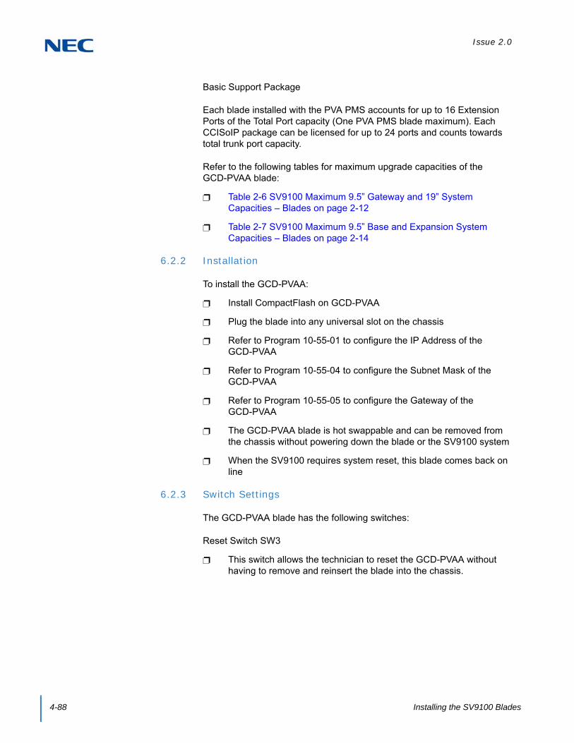
Issue 2.0
4-88 Installing the SV9100 Blades
Basic Support Package
Each blade installed with the PVA PMS accounts for up to 16 Extension Ports of the Total Port capacity (One PVA PMS blade maximum). Each CCISoIP package can be licensed for up to 24 ports and counts towards total trunk port capacity.
Refer to the following tables for maximum upgrade capacities of the GCD-PVAA blade:
Table 2-6 SV9100 Maximum 9.5” Gateway and 19” System Capacities – Blades on page 2-12
Table 2-7 SV9100 Maximum 9.5” Base and Expansion System Capacities – Blades on page 2-14
6.2.2 Installation
To install the GCD-PVAA:
Install CompactFlash on GCD-PVAA
Plug the blade into any universal slot on the chassis
Refer to Program 10-55-01 to configure the IP Address of the GCD-PVAA
Refer to Program 10-55-04 to configure the Subnet Mask of the GCD-PVAA
Refer to Program 10-55-05 to configure the Gateway of the GCD-PVAA
The GCD-PVAA blade is hot swappable and can be removed from the chassis without powering down the blade or the SV9100 system
When the SV9100 requires system reset, this blade comes back on line
6.2.3 Switch Settings
The GCD-PVAA blade has the following switches:
Reset Switch SW3
This switch allows the technician to reset the GCD-PVAA without having to remove and reinsert the blade into the chassis.

Issue 2.0
SV9100 System Hardware Manual 4-89
6.2.4 LED Indications
Active LED – Green
The Active LED is controlled by the DSP and indicates the board operational status.
Off: Power off
On: Reset
Slow Flash: Board is running but not in sync with the chassis
Fast Flash: Board is in sync with the chassis and operating normally
Busy LED – Red
On: Application problem
CompactFlash Card Activity LED – Red
CompactFlash Card Activity LED is controlled by the IDE controller and indicates read/write activity on the CompactFlash card.
6.2.5 Connectors
Ethernet Connector
This connector is a single 10 Base-T/100 Base-T-X Mbps Ethernet connector. This port has Auto-Medium Dependent Interface Crossover (MDIX) to select either a straight-through or crossover Ethernet cable for connection to a PC.

Issue 2.0
4-90 Installing the SV9100 Blades
6.3 GCD-RGA (Application Gateway)
6.3.1 Description
The GCD-RGA blade is a 4-port switch and router which complies with the Ethernet specification for 10 Base-T, 100 Base-TX and 1000 Base-TX. This blade is compatible in LAN applications using 10Mbps, 100Mbps and 1000Mbs. All ports automatically identify and switch 10 Base-T, 100 Base-TX, 1000 Base-TX and Full/Half-Duplex.
Each GCD-RGA blade comes with a built-in router application that provides the following features:
VoIP Gateway
WAN Router:
DHCP
PPPoE
Static IP
Dynamic DNS
Virtual Private Network (VPN)
Figure 4-38 GCD-RGA Blade
WAN
LAN
USB
Reset
Busy LEDActive LED

Issue 2.0
SV9100 System Hardware Manual 4-91
Quality of Service (QOS):
DiffServ
802.1p
802.1Q
Traffic Shaping for Upstream and Downstream traffic
Firewall:
Denial of Service (DoS) Protection
Black WAN Ping Requests
Multicast Pass Through
VPN Pass Through
Block Web Features (Java, Cookies, Active X, HTTP Proxy)
DMZ
Universal Plug and Play (UPnP)
IP Forwarding (1-1 NAT)
Port Forwarding
Port Range Forwarding
IP Based Access Restriction
Access Policy
Services Management:
FTP
SSH
Telnet
SMTP
HTTP
Custom Service
4-Port Gigabit Ethernet Switch:
Switch Management
64 VLANs
Port Mirroring
Link Aggregation
USB Connection used for on-site software updates and future expansion, based on future applications and features.
Web-Based Administration
Compact Flash Interface
The GCD-RGA compact flash interface is used to support the following application. Refer to the entry for this application for more information:
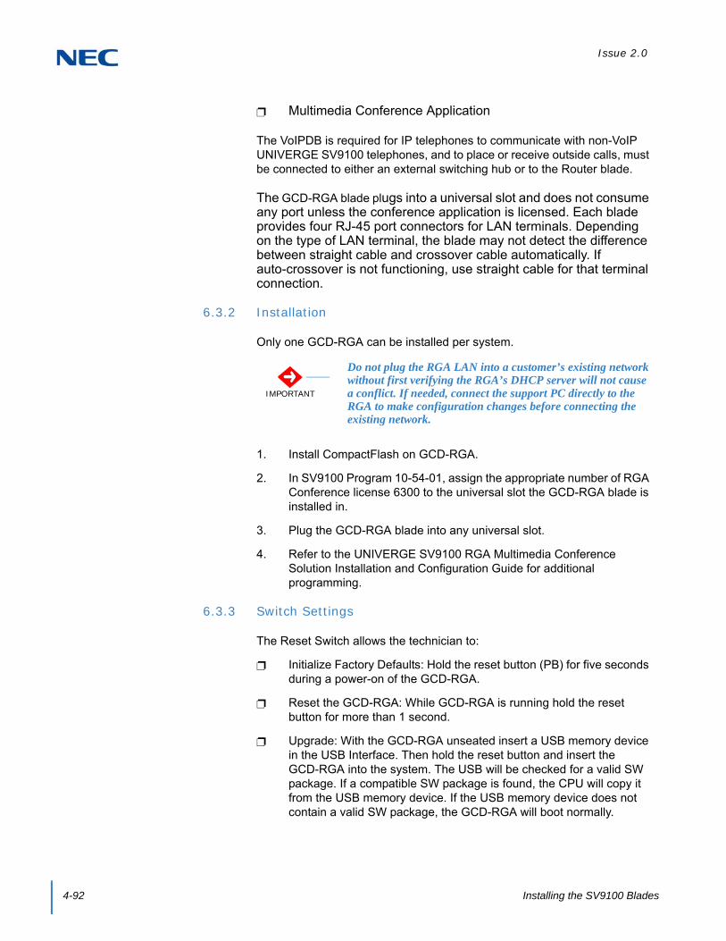
Issue 2.0
4-92 Installing the SV9100 Blades
Multimedia Conference Application
The VoIPDB is required for IP telephones to communicate with non-VoIP UNIVERGE SV9100 telephones, and to place or receive outside calls, must be connected to either an external switching hub or to the Router blade.
The GCD-RGA blade plugs into a universal slot and does not consume any port unless the conference application is licensed. Each blade provides four RJ-45 port connectors for LAN terminals. Depending on the type of LAN terminal, the blade may not detect the difference between straight cable and crossover cable automatically. If auto-crossover is not functioning, use straight cable for that terminal connection.
6.3.2 Installation
Only one GCD-RGA can be installed per system.
1. Install CompactFlash on GCD-RGA.
2. In SV9100 Program 10-54-01, assign the appropriate number of RGA Conference license 6300 to the universal slot the GCD-RGA blade is installed in.
3. Plug the GCD-RGA blade into any universal slot.
4. Refer to the UNIVERGE SV9100 RGA Multimedia Conference Solution Installation and Configuration Guide for additional programming.
6.3.3 Switch Settings
The Reset Switch allows the technician to:
Initialize Factory Defaults: Hold the reset button (PB) for five seconds during a power-on of the GCD-RGA.
Reset the GCD-RGA: While GCD-RGA is running hold the reset button for more than 1 second.
Upgrade: With the GCD-RGA unseated insert a USB memory device in the USB Interface. Then hold the reset button and insert the GCD-RGA into the system. The USB will be checked for a valid SW package. If a compatible SW package is found, the CPU will copy it from the USB memory device. If the USB memory device does not contain a valid SW package, the GCD-RGA will boot normally.
IMPORTANT
Do not plug the RGA LAN into a customer’s existing network without first verifying the RGA’s DHCP server will not cause a conflict. If needed, connect the support PC directly to the RGA to make configuration changes before connecting the existing network.

Issue 2.0
SV9100 System Hardware Manual 4-93
6.3.4 Status LEDs
The table below shows the user-level description of the front panel LEDs in RGA mode.
6.3.5 LED Indications
Active LED – Red/Green
The Active LED is controlled by the DSP and indicates the board operational status. The LED has red/green capability.
Reset: red solid on, green solid on.
GCD-CP10 not detected: solid green.
DSP waiting for application code download: flash green once per second.
Router application running: flash green twice per second.
Voice processor not running: flash red and green (orange) twice per second.
Third party application running: flash green five times per second.
Busy/App LED – Red/Green
The Busy/App LED is controlled by the main processor and indicates the port status. The LED has red/green capability.
Reset or main processor boot problem: red solid on, green solid on (orange).
Main processor booting: solid green.
Router application communicating on backplane: off.
One or more ports active after third party application running: solid red.
Table 4-36 GCD-RGA Status LEDs
ResetReset Just Released
Booting OS
OS Running
Running with 0 License
Apps
Licensed APP on
RGA
Licensed APP is
Running
Licensed App has
Port Busy
Bus LED Red Red Green Green Green Off Off Red
Run LED Orange SF SF MF FF MF FF FF
SFMFFF
Slow FlashMedium FlashFast Flash

Issue 2.0
4-94 Installing the SV9100 Blades
6.3.6 Connectors
10/100/1000 BASE-TX Ethernet Interface
The PVA2 card provides five 10/100/1000 Ethernet interfaces. The LAN ports are used for the local area network connections. The WAN port is used for connecting to other networks or ISP (refer to Table 4-37 GCD-RGA Ethernet Connector Pin-Outs).
Table 4-37 GCD-RGA Ethernet Connector Pin-Outs
View Pin No. 10/100 Signal 1000 Signal Note
1 Tx+ A+
10BASE-T/100BASE-TX/1000BASE-T port
2 Tx- A-
3 RX+ B+
4 NC C+
5 NC C-
6 RX- B-
7 NC D+
8 NC D-

Issue 2.0
SV9100 System Hardware Manual 4-95
6.4 GCD-ETIA (Gigabit PoE Switch)
6.4.1 Description
The GCD-ETIA blade is a managed 8-port gigabit Ethernet PoE switch. Ports 1 and 8 are the default uplink ports. All the user management and stacking are based on this setup. This blade provides:
8 Gigabit Ethernet (10 Base-T/100 Base-TX/1000 Base-T) Ports
Per Port Status LED Indicating Link, Speed and Activity
802.3af PoE on All Ports Providing up to 15.4W of Power- Selectable level per port via web-based management interface
Auto-MDI/MDI-X Auto Crossover (when auto-negotiation is available)
Layer 2 Switching
QoS
802.1Q VLANs
802.1p Priority Queuing
Figure 4-39 GCD-ETIA Blade
Issue 2.0
4-96 Installing the SV9100 Blades
Port Mirroring
802.3x Flow Control
Independent VLAN Learning Support
TCP/IP Networking Stack
Multi-Unit Stacking (multiple blades in a system are managed from the same user interface)
Dynamic PoE Control (allows setting the proper PoE classifications for each port to stay within the system power budget)
Switch Management Through Web-Based GUI
Software Upgrades Via TFTP
Refer to the following tables for maximum upgrade capacities of the GCD-ETIA blade:
Table 2-6 SV9100 Maximum 9.5” Gateway and 19” System Capacities – Blades on page 2-12
Table 2-6 SV9100 Maximum 9.5” Gateway and 19” System Capacities – Blades on page 2-12
6.4.2 Installation
6.4.2.1 Stacking Architecture
Stacking allows the user to manage the multiple Gigabit Switch Unit (GSWU) cards in one system as one switch, instead of individual units and IP addresses. For example, a set of three blades would appear to the UI as a 24 port switch instead of three 8-port switches. Stacking works by assigning a Master Management Card which provides all the GUI information for all the blades in the same stack. The CCPU assigns the Master by issuing an IP address via PAW/PRW. All other GSWU cards detected in the system are assigned as Slave blades.
A single system can have up to 12 GSWU cards per system. However, only three GSWU units can be grouped together forming a single 20 port switch. When more than three GSWU units are present in a system, the additional units do not have any software feature specified in this document. They behave as an unmanaged Gigabit Ethernet switch.
The three GSWU boards can be categorized into one Main board, with two Add-on boards.

Issue 2.0
SV9100 System Hardware Manual 4-97
6.4.2.2 GCD-CP10 IP Address Assignment
The GSWU Main board is provided with an IP address from the back plane CPU during the initialization sequence. The provision of an IP address from the back plane identifies the Main board. If the IP address is set to 0 by the CPU during initialization, the blade is determined to be an Add-on.
The IP address for the GSWU is assigned in Program 10-55 on the system. It contains the settings for the IP Address, Subnet Mask and Gateway IP Address.
6.4.2.3 Group Formation
When a GSWU determines that it is an Add-on board due to the lack of an IP address from the backplane, it sends a broadcast P2P message (defined in separate documentation) to all the GSWU units in the system until it receives an acknowledge message from the Main board.
The Main board receiving this broadcast message acknowledges by sending port identification information to the Add-on board.
6.4.2.4 Port Number Determination
When a Main board is initialized, the board assigns the first eight ports as port 1 ~ 8. When subsequent Add-on boards’ broadcast messages are received, the Main board assigns port numbers on a first-come, first-serve basis.
To have deterministic port assignment, it is recommended that the Add-on boards be inserted sequentially starting with the desired lower port numbers first.
When a board is removed, the port numbers are not automatically removed. The operator, however, can remove any assignment by accessing the Main board GUI.
Example:
Main board is inserted in slot 3, one Add-on board inserted in slot 5. Main board has ports 1 ~ 8; Add-on board has ports 9 ~ 16.
1. User inserts a new Add-on board in slot 2.
The new board gets assigned ports 17 ~ 24.
2. User removes Add-on board and moves it to slot 6.
The re-inserted board automatically gets ports 17 ~ 24 (9 ~ 16 are unavailable)
User can erase the ports 9 ~ 16.
Then reinsert the board in slot 6 to get ports 9 ~ 16.

Issue 2.0
4-98 Installing the SV9100 Blades
3. User relocates the Main board to slot 4.
None of the port numbers change. However, the programming in Program 10-55 must be changed to reflect this move
The grouping of the three GSWU units to form a 20 port switch is restricted to reside in a single system location. The grouping is not allowed where the GSWU units are placed as part of the NetLink feature in the Univerge SV9100 system.
6.4.2.5 Unmanaged Switch Functions
In the unmanaged mode, a GSWU unit has the following functions only:
10 Base-T/100 Base-TX/1000 Base-T) Ethernet ports (x8)
PoE Class 3 (lowest power class)
6.4.3 LED Indications
Table 4-38 GCD-ETIA LED Indications lists the LEDs and provides a describes what the LED indicates.
6.4.4 Connectors
Backplane Connector – J1 connection to system CPU board and other boards in the chassis.
Table 4-38 GCD-ETIA LED Indications
Port State LED Display
1000Mbps Link Green Solid
10/100Mbps Link Yellow Solid
No Link Off
Port Activity LED Blinking

Issue 2.0
SV9100 System Hardware Manual 4-99
SECTION 7 CABLING AND MDF CONNECTION
7.1 Connection Requirements
The chassis is connected to each multiline terminal, single line telephone, optional equipment, GCD-PVAA, DID/OPX, E&M Tie lines and digital trunks by a separate twisted-pair cable through the Main Distribution Frame (MDF). The E&M Tie lines are T1/FT1 lines and require multiple twisted pair cabling.
7.2 Cabling Precautions
When selecting cables and the MDF, future expansion or assignment changes should be given due consideration. Avoid running cables in the following places:
A place exposed to the wind or rain.
A place near heat radiating equipment or where the PVC covering could be affected by gases or chemicals.
An unstable place subject to vibration.
7.3 Wiring Between the Chassis and the MDF
7.3.1 Chassis Cables
The chassis is equipped with two MDF Cable Assemblies. NEC recommends that the MDF Cable Assembly be used to connect the multiline terminals, single line telephones (except PFT), PVAA and DID/OPX lines. Refer to Figure 4-40 MDF Pin-Out (Connectors 1~6) and Table 4-40 MDF Cable Connections (Station) on page 4-100 or Table 4-41 MDF Cable Connections (Trunk) on page 4-102. When installing E&M Tie lines, single line telephones with PFT, and other optional equipment with the GCD-8DLCA/GCD-16DLCA, the connector and cabling must be locally provided.
Figure 4-40 MDF Pin-Out (Connectors 1~6)
12345678
4
5
3
6
2
7
1
8

Issue 2.0
4-100 Installing the SV9100 Blades
Table 4-39 MDF Cable Colors
Pin Outs
Cable Colors
1 2 3 4 5 6
1 BR–WH GN–RD BR–BK BL–YL SL–YL BR–VI
2 GN–WH OR–RD BL–BK SL–BK BR–YL GN–VI
3 OR–WH BL–RD SL–RD BR–GN GN–YL OR–VI
4 WH–BL WH–SL RD–BR BK–GN YL–OR VI–BL
5 BL–WH SL–WH BR–RD GN–BK OR–YL BL–VI
6 WH–OR RD–BL RD–SL GN–BR YL–GN VI–OR
7 WH–GN RD–OR BK–BL BK–SL YL–BR VI–GN
8 WH–BR RD–GN BK–OR YL–BL YL–SL VI–BR
Table 4-40 MDF Cable Connections (Station)
ConnectorMDF
Pin No.Running
Cable
Station CableDTL
DLCA LCA LTA
8 16 4 8 DLCA LCA BRI COT
1
261
WH–BLBL–WH
GNRD
TR
TR
TR
TR
TR
TR
TA–1TB–1
TR
272
WH–OROR–WH
GNRD
TR
TR
TR
TR
TR
TR
RA–1RB–1
TR
283
WH–GNGN–WH
GNRD
TR
TR
TR
TR
TR
TR
TA–2TB–2
TR
294
WH–BRBR–WH
GNRD
TR
TR
TR
TR
TR
TR
RA–2RB–2
TR
2
305
WH–SLSL–WH
GNRD
TR
TR
TR
TR
TR
TR
TA–1TB–1
TR
316
RD–BLBL–RD
GNRD
TR
TR
TR
TR
TR
TR
RA–1RB–1
TR
327
RD–OROR–RD
GNRD
TR
TR
TR
TR
TR
TR
TA–2TB–2
TR
338
RD–GNGN–RD
GNRD
TR
TR
TR
TR
TR
TR
RA–2RB–2
TR

Issue 2.0
SV9100 System Hardware Manual 4-101
3
349
RD–BRBR–RD
GNRD
TR
TR
TR
TR
TR
TR
TA–1TB–1
TR
3510
RD–SLSL–RD
GNRD
TR
TR
TR
TR
TR
TR
RA–1RB–1
TR
3611
BK–BLBL–BK
GNRD
TR
TR
TR
TR
TR
TR
TA–2TB–2
TR
3712
BK–OROR–BK
GNRD
TR
TR
TR
TR
TR
TR
RA–2RB–2
TR
4
3813
BK–GNGN–BK
GNRD
TR
TR
TR
TR
TR
TR
TA–1TB–1
TR
3914
BK–BRBR–BK
GNRD
TR
TR
TR
TR
TR
TR
RA–1RB–1
TR
4015
BK–SLSL–BK
GNRD
TR
TR
TR
TR
TR
TR
TA–2TB–2
TR
4116
YL–BLBL–YL
GNRD
TR
TR
TR
TR
TR
TR
RA–2RB–2
TR
5
4217
YL–OROR–YL
GNRD
TR
TR
TR
TR
TR
TR
TA–1TB–1
TR
4318
YL–GNGN–YL
GNRD
TR
TR
TR
TR
TR
TR
RA–1RB–1
TR
4419
YL–BRBR–YL
GNRD
TR
TR
TR
TR
TR
TR
TA–2TB–2
TR
4520
YL–SLSL–YL
GNRD
TR
TR
TR
TR
TR
TR
RA–2RB–2
TR
6
4621
VI–BLBL–VI
GNRD
TR
TR
TR
TR
TR
TR
TA–1TB–1
TR
4722
VI–OROR–VI
GNRD
TR
TR
TR
TR
TR
TR
RA–1RB–1
TR
4823
VI–GNGN–VI
GNRD
TR
TR
TR
TR
TR
TR
TA–2TB–2
TR
4924
VI–BRBR–VI
GNRD
TR
TR
TR
TR
TR
TR
RA–2RB–2
TR
50 – – – – – – – – – –
25 – – – – – – – – – –
Table 4-40 MDF Cable Connections (Station) (Continued)
ConnectorMDF
Pin No.Running
Cable
Station CableDTL
DLCA LCA LTA
8 16 4 8 DLCA LCA BRI COT

Issue 2.0
4-102 Installing the SV9100 Blades
Table 4-41 MDF Cable Connections (Trunk)
ConnectorMDFPin No.
Running Cable
Station CableDTL
COT( ) DIOPB PRTABRIA CCTA
4 8 DID OPX PRI T1
1
261
WH–BLBL–WH
GNRD
TR
TR
TR
TR
RARB
RARB
TA–1TB–1
RARB
272
WH–OROR–WH
GNRD
TR
TR
TR
TR
–TA
–TA
RA–1RB–1
–TA
283
WH–GNGN–WH
GNRD
TR
TR
TR
TR
TB–
TB–
TA–2TB–2
TB–
294
WH–BRBR–WH
GNRD
TR
TR
TR
TR
––
––
RA–2RB–2
––
2
305
WH–SLSL–WH
GNRD
TR
TR
TR
TR
RARB
RARB
TA–1TB–1
RARB
316
RD–BLBL–RD
GNRD
TR
TR
TR
TR
–TA
–TA
RA–1RB–1
–TA
327
RD–OROR–RD
GNRD
TR
TR
TR
TR
TB–
TB–
TA–2TB–2
TB–
338
RD–GNGN–RD
GNRD
TR
TR
TR
TR
––
––
RA–2RB–2
––
3
349
RD–BRBR–RD
GNRD
TR
TR
TR
TR
RARB
RARB
TA–1TB–1
RARB
3510
RD–SLSL–RD
GNRD
TR
TR
TR
TR
–TA
–TA
RA–1RB–1
–TA
3611
BK–BLBL–BK
GNRD
TR
TR
TR
TR
TB–
TB–
TA–2TB–2
TB–
3712
BK–OROR–BK
GNRD
TR
TR
TR
TR
––
––
RA–2RB–2
––
4
3813
BK–GNGN–BK
GNRD
TR
TR
TR
TR
RARB
RARB
TA–1TB–1
RARB
3914
BK–BRBR–BK
GNRD
TR
TR
TR
TR
–TA
–TA
RA–1RB–1
–TA
4015
BK–SLSL–BK
GNRD
TR
TR
TR
TR
TB–
TB–
TA–2TB–2
TB–
4116
YL–BLBL–YL
GNRD
TR
TR
TR
TR
––
––
RA–2RB–2
––
5
4217
YL–OROR–YL
GNRD
TR
TR
TR
TR
RARB
RARB
TA–1TB–1
RARB
4318
YL–GNGN–YL
GNRD
TR
TR
TR
TR
–TA
–TA
RA–1RB–1
–TA
4419
YL–BRBR–YL
GNRD
TR
TR
TR
TR
TB–
TB–
TA–2TB–2
TB–
4520
YL–SLSL–YL
GNRD
TR
TR
TR
TR
––
––
RA–2RB–2
––

Issue 2.0
SV9100 System Hardware Manual 4-103
7.3.2 Outside Lines
An RJ-61 connector is authorized by the FCC for connection of CO lines. The lines are connected in sequence in this termination block. Therefore, the lines must be ordered in the appearance order best suited to the user. Refer to Table 4-40 MDF Cable Connections (Station) on page 4-100 or Table 4-41 MDF Cable Connections (Trunk) on page 4-102 for information about the MDF Connector Assembly Cable positions, the cable number, and lead functions.
Ground Start and/or Loop Start, Loop Dial, DID/OPX, E&M Tie lines, and E1 trunks can be connected to this system. Using only twisted-pair wiring to cross connect the lines from the RJ-61 termination block to the MDF is recommended.
6
4621
VI–BLBL–VI
GNRD
TR
TR
TR
TR
RARB
RARB
TA–1TB–1
RARB
4722
VI–OROR–VI
GNRD
TR
TR
TR
TR
–TA
–TA
RA–1RB–1
–TA
4823
VI–GNGN–VI
GNRD
TR
TR
TR
TR
TB–
TB–
TA–2TB–2
TB–
4924
VI–BRBR–VI
GNRD
TR
TR
TR
TR
––
––
RA–2RB–2
––
50 – – – – – – – – – –
25 – – – – – – – – – –
Table 4-41 MDF Cable Connections (Trunk) (Continued)
ConnectorMDFPin No.
Running Cable
Station CableDTL
COT( ) DIOPB PRTABRIA CCTA
4 8 DID OPX PRI T1

Issue 2.0
4-104 Installing the SV9100 Blades

SV9100 System Hardware Manual 5-1
Chapter 5
UNIVERGE® SV9100
Installing DT Series Digital and IP Multiline Terminals
SECTION 1 GENERAL DESCRIPTION
This chapter provides information about the DT series Digital and IP terminals in addition to the single line telephones, cordless telephones and wireless telephones.
Only the DT series, single line telephones, cordless telephones and wireless telephones discussed in the document can be installed on the SV9100 system.
Table 5-1 Terminal Category Reference Chart on page 5-1 provides a quick reference of the DT series Digital and IP multiline terminals.
WARNING
To avoid damage to equipment, do not install the Dterm70 on the SV9100 system. The Dterm70 (DTU/DTP) terminal uses -24V and has no protection from the -48V power supply used by the SV9100 system.
Table 5-1 Terminal Category Reference Chart
Series NameEquipment
IDComments
DT300 SeriesDigital Terminal (TDM)
DT310(Economy)
DTL-2E-( )DTL-6DE-( )DTL-12E-( )
Economical terminal providing access to basic telephony and messaging service
Fully functional keypad providing standard business functions such as hold, transfer, speaker, microphone and other features
2-button terminal is non-display 6-button terminal equipped with LCD and full-featured keypad 12-button terminal is non-display Available in black
DT330(Value)
DTL-8LD-( )DTL-12D-( )DTL-24D-( )DTL-32D-( )
8-button DESI-Less LCD telephone Also available are 12-, 24-, 32-button LCD telephones Provides access to more sophisticated system features and allowing room for
growth All DT 330s come with a standard LCD display, full duplex speakerphone
capability, module support for expansion and feature add-on capability Optional 60-button DSS Console provides 60 programmable keys and provides
users a Busy Lamp Field (BLF) and 1-button access to extensions, trunks, and system features
Available in black and white
DTL-12BT( ) Bluetooth available in black
DTL-12PA( ) Power Save Adapter provides backup for analog trunk connection

Issue 2.0
5-2 Installing DT Series Digital and IP Multiline Terminals
DT400 SeriesDigital Terminal (TDM)
DT410(Economy)
DTZ-2E-( )DTZ-6DE-( )
Economical terminal providing access to basic telephony and messaging service
Fully functional keypad providing standard business functions such as hold, transfer, speaker, microphone and other features
2-button terminal is non-display 6-button terminal equipped with LCD and full-featured keypad Available in black
DT430(Value)
DTZ-8LD-( )DTZ-12D-( )DTZ-24D-( )
8-button DESI-Less LCD telephone Also available are 12-, 24-, 32(24D+8LK)-button LCD telephones Provides access to more sophisticated system features and allowing room for
growth All DT 430s come with a standard LCD display, full duplex speakerphone
capability, module support for expansion and feature add-on capability Optional 60-button DSS Console provides 60 programmable keys and provides
users a Busy Lamp Field (BLF) and 1-button access to extensions, trunks, and system features
Available in black and white
Table 5-1 Terminal Category Reference Chart
Series NameEquipment
IDComments

Issue 2.0
SV9100 System Hardware Manual 5-3
DT700 SeriesIP Terminals
DT710(Economy)
ITL-2E-( )ITL-6DE-( )ITL-8LDE-( )
Economical terminal providing access to basic telephony and messaging service
Fully functional keypad providing standard business functions such as hold, transfer, speaker, microphone and other features
2-button terminal is non-display 6-button terminal equipped with LCD and full-featured keypad 8-button terminal equipped with LCD and full-featured keypad Available in black IP formatted terminal has a dual port, supports compression, full-duplex
handsfree operation
DT730(Value)
ITL-8LD-( )ITL-12D-( )ITL-24D-( )ITL-32D-( )
8-button DESI-Less LCD telephone Also available are 12-, 24-, 32(24D+8LK)-button LCD telephones Provides access to more sophisticated system features allowing room for
growth All DT 730s come with a standard backlit LCD display, full duplex speakerphone
capability, module support for expansion and feature add-on capability Available in black and white Expands the capability by providing XML display to provide more productivity
enhanced applications to the users Optional 60-button DSS Console provides 60 programmable keys and provides
users a Busy Lamp Field (BLF) and 1-button access to extensions, trunks, and system features
ITL-12PA( ) Power Save Adapter provides backup for analog trunk connection
DT730G(Value)
ITL-12CG-( )ITL-12DG-( )
Provides access to more sophisticated system features allowing room for growth
DT 730G terminals come with a standard back-lit LCD display, full duplex speakerphone capability, module support for expansion and feature add-on capability
Available in black only Expands the capability by providing XML display to provide more productivity
enhanced applications to the users 12CG equipped with color LCD display 12CG/12DG support Gigabit Ethernet
DT750(Sophisticated)
ITL-320C-( ) IP terminal provides a 5” color touch panel Features of the telephone provide easy use of NEC Unified communications
and third-party telephony XML applications Access to 32 telephony feature lines across an IP backbone, built-in full duplex
speakerphone and DESI-Less line key labeling are standard Optional 60-button DSS Console provides 60 programmable keys and provides
users a Busy Lamp Field (BLF) and one-button access to extensions, trunks, and system features
Table 5-1 Terminal Category Reference Chart
Series NameEquipment
IDComments

Issue 2.0
5-4 Installing DT Series Digital and IP Multiline Terminals
The DT Series offers a line up of modular telephones. This modular design allows the telephones to be upgraded and customized. Optional LCD panels, keypads, handset cradles, face plates and colored side panels can easily be snapped on and off.
The easy-to-use adjustable footplate allows a variety of height positions.
Several easy-to-read LCD displays are available, including a new large color touch panel LCD.
Table 5-2 Terminal and Adapter Compatibility (DT300/DT700) and Table 5-3 Terminal and Adapter Compatibility (DT400/DT800) on page 5-6 show the compatibility between the terminals and adapters used in the system.
DT800 SeriesIP Terminals
DT830(Value)
ITZ-8LD-( )ITZ-8LDG-( )ITZ-12D-( )ITZ-24D-( )
8-button DESI-Less LCD telephone Also available are 12-, 24-, 32(24D+8LK)-button LCD telephones Provides access to more sophisticated system features allowing room for
growth All DT 830s come with a standard backlit LCD display, full duplex speakerphone
capability, module support for expansion and feature add-on capability Available in black and white Expands the capability by providing XML display to provide more productivity
enhanced applications to the users Optional 60-button DSS Console provides 60 programmable keys and provides
users a Busy Lamp Field (BLF) and 1-button access to extensions, trunks, and system features
DT830G(Value)
ITZ-12CG-( )ITZ-12DG-( )
Provides access to more sophisticated system features allowing room for growth
DT 830G terminals come with a standard back-lit LCD display, full duplex speakerphone capability, module support for expansion and feature add-on capability
Available in black only Expands the capability by providing XML display to provide more productivity
enhanced applications to the users 12CG equipped with color LCD display 12CG/12DG support Gigabit Ethernet
Table 5-1 Terminal Category Reference Chart
Series NameEquipment
IDComments
Table 5-2 Terminal and Adapter Compatibility (DT300/DT700)
TerminalAdapter Unit
ADA-L APR-L ILPA PSA-L BCH-L BHA-L GBA-L
Digital Terminals: DT300
DTL-2E-1 (BK) TEL — — — — — — —
DTL-6DE-1 (BK) TEL — — — — — — —
DTL-12E-1 (BK) TEL — — — — — — —

Issue 2.0
SV9100 System Hardware Manual 5-5
DTL-8LD(BK)/(WH) TEL — —
DTL-12BT-1 (BK) TEL — — — — — — —
DTL-12D-1 (BK)/(WH) TEL — —
DTL-12PA-1 (BK) TEL — — — —
DTL-24D-1 (BK)/(WH) TEL — —
DTL-32D-1 (BK)/(WH) TEL — —
IP Terminals: DT700
ITL-2E-1 (BK) TEL — — — — —
ITL-6DE-1 (BK) TEL — — — — —
ITL-8LDE-1 (BK) TEL — — — — —
ITL-8LD-1 (BK)/(WH) TEL — — —
ITL-12D-1 (BK)/(WH) TEL — — —
ITL-12CG-3 (BK) TEL — — — Note2
ITL-12DG-3 (BK) TEL — — — Note2
ITL-12PA-1 (BK) TEL — — —
ITL-24D-1 (BK)/(WH) TEL — — —
ITL-32D-1 (BK)/(WH) TEL — — —
ITL-320C-1 (BK) TEL — — —
Console:
DCL-60-1 (BK)/(WH) CONSOLE — — — — — — —
— = Option Not Available
= Optional Available1 = When the ILPA-R is connected to a 12CG/12DG terminal, maximum connection speed drops to 100Mbps.2 = The 12CG/12DG terminals support Gigabit Ethernet, GBA-L Unit not required.
Table 5-2 Terminal and Adapter Compatibility (DT300/DT700) (Continued)
TerminalAdapter Unit
ADA-L APR-L ILPA PSA-L BCH-L BHA-L GBA-L

Issue 2.0
5-6 Installing DT Series Digital and IP Multiline Terminals
Table 5-3 Terminal and Adapter Compatibility (DT400/DT800)
TerminalAdapter Unit
ADA-L APR-L ILPA BHA-Z BCA-Z
Digital Terminals: DT400
DTZ-2E-3 (BK) TEL — — — — —
DTZ-6DE-3 (BK) TEL — — — — —
DTZ-12D-3 (BK)/(WH) TEL —
DTZ-24D-3 (BK)/(WH) TEL —
DTZ-8LD-3 (BK)/(WH) TEL —
IP Terminals: DT800
ITZ-8LD-3 (BK) TEL — —
ITZ-12D-3 (BK)/(WH) TEL — —
ITZ-24D-3 (BK)/(WH) TEL — —
ITZ-12CG-3 (BK)/(WH) TEL — —
ITZ-12DG-3 (BK)/(WH) TEL — —
ITZ-8LDG-3 (BK)/(WH) TEL — —
Console:
DCZ-60-2 (BK)/(WH) CONSOLE — — — — —
= When the ILPA-R unit is used, 1000 BASE-T is not available.
Table 5-4 Firmware Compatibility Matrix
BCH-L Unit Lot Number
xxxDxx or lower xxxExx or higher
Terminal Lot
Number DT-330
xxx I xx or lower(Version 8.10 and 1, E0 or lower)
Supported Supported
xxxJxx or higher(Version 2.20 or higher)
Not supported Supported
BCH Support may differ based on terminal firmware. To verify both DT-330 terminal and BCH-L Unit firmware, hold down keypad buttons 1, 2 and 3 while plugging the line cord into the terminal.
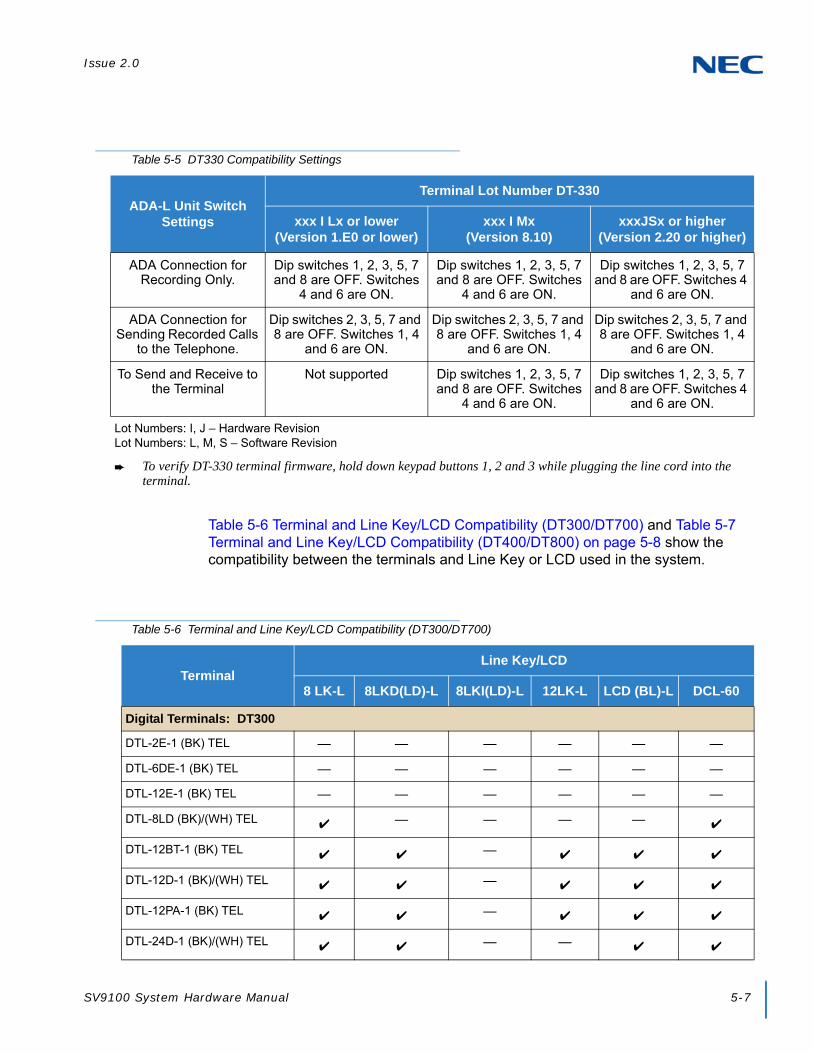
Issue 2.0
SV9100 System Hardware Manual 5-7
Table 5-6 Terminal and Line Key/LCD Compatibility (DT300/DT700) and Table 5-7 Terminal and Line Key/LCD Compatibility (DT400/DT800) on page 5-8 show the compatibility between the terminals and Line Key or LCD used in the system.
Table 5-5 DT330 Compatibility Settings
ADA-L Unit Switch Settings
Terminal Lot Number DT-330
xxx I Lx or lower(Version 1.E0 or lower)
xxx I Mx(Version 8.10)
xxxJSx or higher(Version 2.20 or higher)
ADA Connection for Recording Only.
Dip switches 1, 2, 3, 5, 7 and 8 are OFF. Switches
4 and 6 are ON.
Dip switches 1, 2, 3, 5, 7 and 8 are OFF. Switches
4 and 6 are ON.
Dip switches 1, 2, 3, 5, 7 and 8 are OFF. Switches 4
and 6 are ON.
ADA Connection for Sending Recorded Calls
to the Telephone.
Dip switches 2, 3, 5, 7 and 8 are OFF. Switches 1, 4
and 6 are ON.
Dip switches 2, 3, 5, 7 and 8 are OFF. Switches 1, 4
and 6 are ON.
Dip switches 2, 3, 5, 7 and 8 are OFF. Switches 1, 4
and 6 are ON.
To Send and Receive to the Terminal
Not supported Dip switches 1, 2, 3, 5, 7 and 8 are OFF. Switches
4 and 6 are ON.
Dip switches 1, 2, 3, 5, 7 and 8 are OFF. Switches 4
and 6 are ON.
Lot Numbers: I, J – Hardware RevisionLot Numbers: L, M, S – Software Revision
To verify DT-330 terminal firmware, hold down keypad buttons 1, 2 and 3 while plugging the line cord into the terminal.
Table 5-6 Terminal and Line Key/LCD Compatibility (DT300/DT700)
TerminalLine Key/LCD
8 LK-L 8LKD(LD)-L 8LKI(LD)-L 12LK-L LCD (BL)-L DCL-60
Digital Terminals: DT300
DTL-2E-1 (BK) TEL — — — — — —
DTL-6DE-1 (BK) TEL — — — — — —
DTL-12E-1 (BK) TEL — — — — — —
DTL-8LD (BK)/(WH) TEL — — — —
DTL-12BT-1 (BK) TEL —
DTL-12D-1 (BK)/(WH) TEL —
DTL-12PA-1 (BK) TEL —
DTL-24D-1 (BK)/(WH) TEL — —

Issue 2.0
5-8 Installing DT Series Digital and IP Multiline Terminals
DTL-32D-1 (BK)/(WH) TEL — —
IP Terminals: DT700
ITL-2E-1 (BK) TEL — — — — — —
ITL-6DE-1 (BK) TEL — — — — — —
ITL-8LDE-1 (BK) TEL — — — — — —
ITL-8LD-1 (BK)/(WH) TEL — — — —
ITL-12D-1 (BK)/(WH) TEL — —
ITL-12CG-3 (BK) TEL — — —
ITL-12DG-3 (BK) TEL — — —
ITL-12PA-1 (BK) TEL — —
ITL-24D-1 (BK)/(WH) TEL — — —
ITL-32D-1 (BK)/(WH) TEL — — —
ITL-320C-1 (BK) TEL/ITL-320C-2 (BK) TEL
— — — —
— = Option Not Available
= Optional Available
Table 5-6 Terminal and Line Key/LCD Compatibility (DT300/DT700) (Continued)
TerminalLine Key/LCD
8 LK-L 8LKD(LD)-L 8LKI(LD)-L 12LK-L LCD (BL)-L DCL-60
Table 5-7 Terminal and Line Key/LCD Compatibility (DT400/DT800)
TerminalLine Key/LCD
8 LK-Z 16LK-Z DCZ-60
Digital Terminals: DT400
DTZ-2E-3 (BK) TEL — — —
DTZ-6DE-3 (BK) TEL — — —
DTZ-12D-3 (BK)/(WH) TEL —
DTZ-24D-3 (BK)/(WH) TEL —
DTZ-8LD-3 (BK)/(WH) TEL —

Issue 2.0
SV9100 System Hardware Manual 5-9
Table 5-8 Terminal and Ten Key Kit Compatibility (DT300/DT700) and Table 5-9 Terminal and Ten Key Kit Compatibility (DT400/DT800) on page 5-10 show the compatibility between the terminals and Ten Key kits used in the system.
IP Terminals: DT800
ITZ-8LD-3 (BK) TEL — — —
ITZ-12D-3 (BK)/(WH) TEL — — —
ITZ-24D-3 (BK)/(WH) TEL — — —
ITZ-12CG-3 (BK)/(WH) TEL —
ITZ-12DG-3 (BK)/(WH) TEL —
ITZ-8LDG-3 (BK)/(WH) TEL —
— = Option Not Available
= Optional Available
Table 5-8 Terminal and Ten Key Kit Compatibility (DT300/DT700)
Terminal
Ten Key Kit
BS(F)-L BS(S)-LSticker-
Braille-L KITBS(Retro)-l
BS(S-Hotel)
Digital Terminals: DT300
DTL-2E-1 (BK) TEL — — — —
DTL-6DE-1 (BK) TEL — — — —
DTL-12E-1 (BK) TEL — — — —
DTL-8LD (BK)/(WH) TEL —
DTL-12D-1 (BK)/(WH) TEL —
DTL-12BT-1 (BK) TEL —
DTL-12PA-1 (BK) TEL —
DTL-24D-1 (BK)/(WH) TEL —
DTL-32D-1 (BK)/(WH) TEL —
Table 5-7 Terminal and Line Key/LCD Compatibility (DT400/DT800) (Continued)
TerminalLine Key/LCD
8 LK-Z 16LK-Z DCZ-60
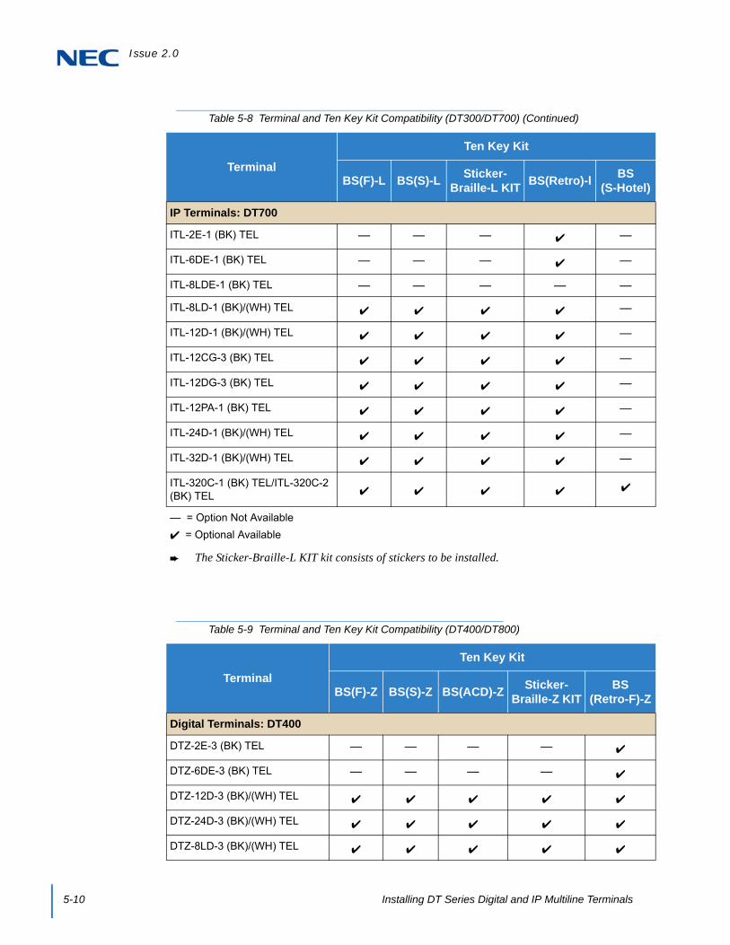
Issue 2.0
5-10 Installing DT Series Digital and IP Multiline Terminals
IP Terminals: DT700
ITL-2E-1 (BK) TEL — — — —
ITL-6DE-1 (BK) TEL — — — —
ITL-8LDE-1 (BK) TEL — — — — —
ITL-8LD-1 (BK)/(WH) TEL —
ITL-12D-1 (BK)/(WH) TEL —
ITL-12CG-3 (BK) TEL —
ITL-12DG-3 (BK) TEL —
ITL-12PA-1 (BK) TEL —
ITL-24D-1 (BK)/(WH) TEL —
ITL-32D-1 (BK)/(WH) TEL —
ITL-320C-1 (BK) TEL/ITL-320C-2 (BK) TEL
— = Option Not Available
= Optional Available
The Sticker-Braille-L KIT kit consists of stickers to be installed.
Table 5-9 Terminal and Ten Key Kit Compatibility (DT400/DT800)
Terminal
Ten Key Kit
BS(F)-Z BS(S)-Z BS(ACD)-ZSticker-
Braille-Z KITBS
(Retro-F)-Z
Digital Terminals: DT400
DTZ-2E-3 (BK) TEL — — — —
DTZ-6DE-3 (BK) TEL — — — —
DTZ-12D-3 (BK)/(WH) TEL
DTZ-24D-3 (BK)/(WH) TEL
DTZ-8LD-3 (BK)/(WH) TEL
Table 5-8 Terminal and Ten Key Kit Compatibility (DT300/DT700) (Continued)
Terminal
Ten Key Kit
BS(F)-L BS(S)-LSticker-
Braille-L KITBS(Retro)-l
BS(S-Hotel)

Issue 2.0
SV9100 System Hardware Manual 5-11
Table 5-10 Terminal and Optional Equipment Compatibility (DT300/DT700) and Table 5-11 Terminal and Optional Equipment Compatibility (DT400/DT800) on page 5-13 show the compatibility between the terminals and optional equipment used in the system.
IP Terminals: DT800
ITZ-8LD-3 (BK) TEL
ITZ-12D-3 (BK)/(WH) TEL
ITZ-24D-3 (BK)/(WH) TEL
ITZ-12CG-3 (BK)/(WH) TEL
ITZ-12DG-3 (BK)/(WH) TEL
ITZ-8LDG-3 (BK)/(WH) TEL
— = Option Not Available
= Optional Available
The Sticker-Braille-Z kit consists of stickers to be installed.
Table 5-10 Terminal and Optional Equipment Compatibility (DT300/DT700)
TerminalEquipment
PSA-L WM-L1 PANEL-L
Digital Terminals: DT300
DTL-2E-1 (BK) TEL —
DTL-6DE-1 (BK) TEL —
DTL-12E-1 (BK) TEL —
DTL-8LD (BK)/(WH) TEL
DTL-12BT-1 (BK) TEL —
DTL-12D-1 (BK)/(WH) TEL
DTL-12PA-1 (BK) TEL —
DTL-24D-1 (BK)/(WH) TEL
Table 5-9 Terminal and Ten Key Kit Compatibility (DT400/DT800) (Continued)
Terminal
Ten Key Kit
BS(F)-Z BS(S)-Z BS(ACD)-ZSticker-
Braille-Z KITBS
(Retro-F)-Z

Issue 2.0
5-12 Installing DT Series Digital and IP Multiline Terminals
DTL-32D-1 (BK)/(WH) TEL
IP Terminals: DT700
ITL-2E-1 (BK) TEL —
ITL-6DE-1 (BK) TEL —
ITL-8LDE-1 (BK) TEL —
ITL-8LD-1 (BK)/(WH) TEL
ITL-12D-1 (BK)/(WH) TEL
ITL-12CG-3 (BK) TEL
ITL-12DG-3 (BK) TEL
ITL-12PA-1 (BK) TEL —
ITL-24D-1 (BK)/(WH) TEL
ITL-32D-1 (BK)/(WH) TEL
ITL-320C-1 (BK) TEL/ITL-320C-2 (BK) TEL
Console:
DCL-60-1 (BK)/(WH) CONSOLE 2 — —
— = Option Not Available
= Optional Available1 The WM-L is required if the ADA-L UNIT or APR-L UNIT is installed on the telephone.2 DCL-60-1 = DSS Wall Mount
Table 5-10 Terminal and Optional Equipment Compatibility (DT300/DT700) (Continued)
TerminalEquipment
PSA-L WM-L1 PANEL-L

Issue 2.0
SV9100 System Hardware Manual 5-13
Table 5-11 Terminal and Optional Equipment Compatibility (DT400/DT800)
TerminalEquipment
WM-L1 PANEL-L
Digital Terminals: DT400
DTZ-2E-3 (BK) TEL
DTZ-6DE-3 (BK) TEL
DTZ-12D-3 (BK)/(WH) TEL
DTZ-24D-3 (BK)/(WH) TEL
DTZ-8LD-3 (BK)/(WH) TEL
IP Terminals: DT800
ITZ-8LD-3 (BK) TEL
ITZ-12D-3 (BK)/(WH) TEL
ITZ-24D-3 (BK)/(WH) TEL
ITZ-12CG-3 (BK)/(WH) TEL
ITZ-12DG-3 (BK)/(WH) TEL
ITZ-8LDG-3 (BK)/(WH) TEL
Console:
DCZ-60-2 (BK)/(WH) CONSOLE 2 —
— = Option Not Available
= Optional Available1 The WM-L is required if the ADA-L UNIT or APR-L UNIT is installed on the telephone.2 DCZ-60-2 = DSS Wall Mount

Issue 2.0
5-14 Installing DT Series Digital and IP Multiline Terminals
SECTION 2 DT300/DT400 SERIES DIGITAL MULTILINE TERMINALS
The DT300/DT400 Series offers a new exciting line up of digital telephones. These telephones (except economy), have a modular design that allows the telephone to be upgraded and customized. Optional LCD panels, dial pads, feature key kits, handset cradles, face plates and colored side panels can easily be snapped on and off to upgrade and customize as the customer desires.
The DT300 Series Digital multiline terminals are supported by the Electra Elite IPK II system (similar to the Dterm Series i Telephones) with optional Retro key pad installed.
2.1 DT300 Series Digital Multiline Terminals
2.1.1 DTL-2E-1 (BK) TEL
This digital economy non-display multiline terminal has two programmable line keys and is available in black only. The terminal features:
Non-modular design
Four-step adjustable base
Half-duplex speaker phone
Two line keys (Red, Green)
Three-color LED
Figure 5-1 DTL-2E-1 TEL

Issue 2.0
SV9100 System Hardware Manual 5-15
2.1.2 DTL-6DE-1 (BK) TEL
This digital economy multiline terminal has six line keys with display and is available in black only. The terminal features:
Non-modular design
Four-step adjustable base
Half-duplex speaker phone
Six line keys (Red, Green)
Four Softkeys (Help, Exit)
Three-color LED
24 X 3 character LCD display
Figure 5-2 DTL-6DE-1 TEL

Issue 2.0
5-16 Installing DT Series Digital and IP Multiline Terminals
2.1.3 DTL-12E-1 (BK) TEL
This digital economy non-display multiline terminal has 12 programmable line keys and is available in black only. The terminal features:
Non-modular design
Four-step adjustable base
Half-duplex speaker phone
12 line keys (Red, Green)
Three-color LED for message waiting and incoming calls
Figure 5-3 DTL-12E-1 TEL

Issue 2.0
SV9100 System Hardware Manual 5-17
2.1.4 DTL-8LD (BK)/(WH) TEL
This digital value multiline terminal has eight line keys with display and is available in both black and white. The terminal features:
Modular design
Four step adjustable base
Full-duplex speaker phone
Eight line keys (Red, Green)
Four Softkeys (Help, Exit)
DESI-Less line key displays eight lines per page (four pages of eight lines available using scroll key)
Three color LED
Two 168 X 55 dot matrix backlit LCDs with cursor keys
Backlit Numbered Keypad for easy viewing
Full-duplex handsfree operation
Figure 5-4 DTL-8LD-1 TEL

Issue 2.0
5-18 Installing DT Series Digital and IP Multiline Terminals
2.1.5 DTL-12BT-1 (BK) TEL
This digital value multiline terminal has 12 line keys and is available in black only. The terminal features:
Keyset-like Handset
12 Line Buttons
Function Button
Dial Button
Display
All multiline terminal functions with Main Unit
Cradle Charges Handset
Base Side RF Block (50 meters, Class 1)
Bluetooth Distance: 50 Meters
Full-duplex handsfree operation
Figure 5-5 DTL-12BT-1 TEL
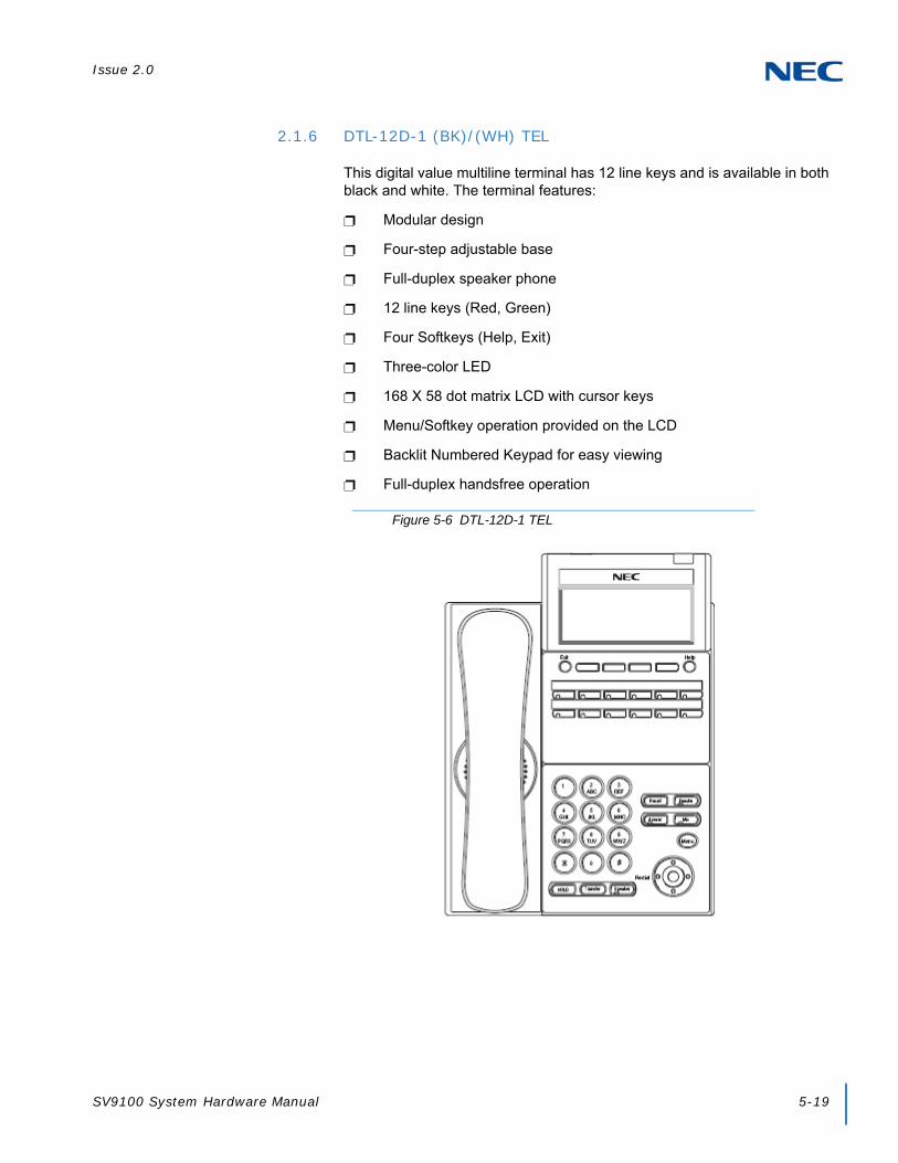
Issue 2.0
SV9100 System Hardware Manual 5-19
2.1.6 DTL-12D-1 (BK)/(WH) TEL
This digital value multiline terminal has 12 line keys and is available in both black and white. The terminal features:
Modular design
Four-step adjustable base
Full-duplex speaker phone
12 line keys (Red, Green)
Four Softkeys (Help, Exit)
Three-color LED
168 X 58 dot matrix LCD with cursor keys
Menu/Softkey operation provided on the LCD
Backlit Numbered Keypad for easy viewing
Full-duplex handsfree operation
Figure 5-6 DTL-12D-1 TEL

Issue 2.0
5-20 Installing DT Series Digital and IP Multiline Terminals
2.1.7 DTL-12PA-1 (BK) TEL
This digital value multiline terminal with Analog Power Failure adapter has 12 line keys and is available in black only. The terminal features:
Modular design
Four-step adjustable base
Full-duplex speaker phone
12 line keys (Red, Green)
Four Softkeys (Help, Exit)
Three-color LED
168 X 58 dot matrix LCD with cursor keys
Menu/Softkey operation provided on the LCD
Backlit Numbered Keypad for easy viewing
Full-duplex handsfree operation
PSA-L adapter
Figure 5-7 DTL-12PA-1 TEL

Issue 2.0
SV9100 System Hardware Manual 5-21
2.1.8 DTL-24D-1 (BK)/(WH) TEL
This digital value multiline terminal has 24 line keys and is available in both black and white. The terminal features:
Modular design
Four-step adjustable base
Full-duplex speaker phone
24 line keys (Red, Green)
Four Softkeys (Help, Exit)
Three-color LED
168 X 58 dot matrix LCD with cursor keys
Menu/Softkey operation provided on the LCD
Backlit Numbered Keypad for easy viewing
Full-duplex handsfree operation
Figure 5-8 DTL-24D-1 TEL

Issue 2.0
5-22 Installing DT Series Digital and IP Multiline Terminals
2.1.9 DTL-32D-1 (BK)/(WH) TEL
This digital value multiline terminal has 32 line keys (24 line keys plus eight line key LK Unit) and is available in both black and white. The terminal features:
Modular design
Four-step adjustable base
Full-duplex speaker phone
32 line keys (Red, Green)
Four Softkeys (Help, Exit)
Three-color LED
168 X 58 dot matrix LCD with cursor keys
Menu/Softkey operation provided on the LCD
Backlit Numbered Keypad for easy viewing
Full-duplex handsfree operation
Figure 5-9 DTL-32D-1 TEL

Issue 2.0
SV9100 System Hardware Manual 5-23
2.2 DT400 Series Digital Multiline Terminals
2.2.1 DTZ-2E-3 (BK) TEL
This digital economy non-display multiline terminal has two programmable line keys and is available in black only. The terminal features:
Non-modular design
Four-step adjustable base
Half-duplex speaker phone
Two line keys (Red, Green)
Three-color LED
Figure 5-10 DTZ-2E-3 TEL

Issue 2.0
5-24 Installing DT Series Digital and IP Multiline Terminals
2.2.2 DTZ-6DE-3 (BK) TEL
This digital economy multiline terminal has six line keys with display and is available in black only. The terminal features:
Non-modular design
Four-step adjustable base
Half-duplex speaker phone
Six line keys (Red, Green)
Four Softkeys (Help, Exit)
Three-color LED
24 X 3 character LCD display
Figure 5-11 DTZ-6DE-3 TEL

Issue 2.0
SV9100 System Hardware Manual 5-25
2.2.3 DTZ-12D-3 (BK)/(WH) TEL
This digital value multiline terminal has 12 line keys and is available in both black and white. The terminal features:
Modular design
Four-step adjustable base
Full-duplex speaker phone
12 line keys (Red, Green)
Four Softkeys (Help, Exit)
Three-color LED
168 X 58 dot matrix LCD with cursor keys
Menu/Softkey operation provided on the LCD
Backlit Numbered Keypad for easy viewing
Full-duplex handsfree operation
Figure 5-12 DTZ-12D-3 TEL

Issue 2.0
5-26 Installing DT Series Digital and IP Multiline Terminals
2.2.4 DTZ-24D-3 (BK)/(WH) TEL
This digital value multiline terminal has 24 line keys and is available in both black and white. The terminal features:
Modular design
Four-step adjustable base
Full-duplex speaker phone
24 line keys (Red, Green)
Four Softkeys (Help, Exit)
Three-color LED
168 X 58 dot matrix LCD with cursor keys
Menu/Softkey operation provided on the LCD
Backlit Numbered Keypad for easy viewing
Full-duplex handsfree operation
Figure 5-13 DTZ-24D-3 TEL

Issue 2.0
SV9100 System Hardware Manual 5-27
2.2.5 DTZ-8LD-3 (BK)/(WH) TEL
This digital value multiline terminal has eight line keys with display and is available in both black and white. The terminal features:
Modular design
Four step adjustable base
Full-duplex speaker phone
Eight line keys (Red, Green)
Four Softkeys (Help, Exit)
DESI-Less line key displays eight lines per page (four pages of eight lines available using scroll key)
Three color LED
Two 168 X 55 dot matrix backlit LCDs with cursor keys
Backlit Numbered Keypad for easy viewing
Full-duplex handsfree operation
Figure 5-14 DTZ-8LD-3 TEL

Issue 2.0
5-28 Installing DT Series Digital and IP Multiline Terminals
SECTION 3 DT700/DT800 SERIES IP MULTILINE TERMINALS
The DT700/DT800 offers a new exciting line up of IP telephones. These telephones (except economy), have a modular design that allows the telephones to be upgraded and customized. Optional LCD panels, dial pads, feature key kits, handset cradles, face plates and colored side panels can easily be snapped on and off to upgrade and customize as the customer desires.
3.1 DT700 Series IP Multiline Terminals
3.1.1 ITL-2E-1 (BK) TEL
This IP economy non-display multiline terminal has two programmable line keys and is available in black only. The terminal features:
Non-modular design
Four-step adjustable base
Full-duplex speaker phone
Three-color LED
IEEE 802.3af compliant
XML open interface (limited)
10 Base-T/100 Base-TX network interface
Remote Login and Maintenance
Figure 5-15 ITL-2E-1 TEL

Issue 2.0
SV9100 System Hardware Manual 5-29
3.1.2 ITL-6DE-1 (BK) TEL
This IP economy multiline terminal has six line keys with display and is available in black only. The terminal features:
Non-modular design
Four-step adjustable base
Remote login and maintenance
Full-duplex speaker phone
Three-color LED for message waiting
168 X 41 full dot black and white LCD with cursor keys
IEEE 802.3af compliant
XML open interface (limited)
10 Base-T/100 Base-TX network interface
Figure 5-16 ITL-6DE-1 TEL

Issue 2.0
5-30 Installing DT Series Digital and IP Multiline Terminals
3.1.3 ITL-8LDE-1 (BK) TEL
This IP economy multiline terminal has eight line keys with display and is available in black only. The terminal features:
Non-Modular design
Four-step adjustable base
Full-duplex speaker phone
DESI-Less line key displays eight lines.
Function key changes from HOME to DESI-Less screen
Three-color LED for message waiting
224 x 96 dot matrix gray scale backlit LCD
IEE 802.af compliant
XML open interface (limited)
10 Base-T/100 Base-TX network interface
Wide Band Handset
Figure 5-17 ITL-8LDE-1 TEL

Issue 2.0
SV9100 System Hardware Manual 5-31
3.1.4 ITL-8LD-1 (BK)/(WH) TEL
This IP value multiline terminal has eight line keys with display and is available in both black and white. The terminal features:
Modular design
Four-step adjustable base
Full-duplex speaker phone
DESI-Less line key displays eight lines per page (four pages of eight lines available using scroll key)
Protection button (lock)
Seven-color LED for incoming calls
Two 224 X 96 full dot gray scale LCDs with cursor keys
Backlit Numbered Keypad for easy viewing
Full-duplex handsfree operation
Wideband handset
IEEE 802.3af compliant
XML open interface
10 Base-T/100 Base-TX network interface
Backlit LCD
Figure 5-18 ITL-8LD-1 TEL

Issue 2.0
5-32 Installing DT Series Digital and IP Multiline Terminals
3.1.5 ITL-12D-1 (BK)/(WH) TEL
This IP value multiline terminal has 12 line keys and is available in both black and white. The terminal features:
Modular design
Four-step adjustable base
Full-duplex speaker phone
Protection button
Seven-color LED for incoming calls
224 X 96 full dot gray scale LCD with cursor keys
Menu/Softkey operation provided on the LCD
Backlit Numbered Keypad for easy viewing
Full-duplex handsfree operation
IEEE 802.3af compliant
XML open interface
10 Base-T/100 Base-TX network interface
Backlit LCD
Figure 5-19 ITL-12D-1 TEL

Issue 2.0
SV9100 System Hardware Manual 5-33
3.1.6 ITL-12/24CG-3 (BK) TEL
This IP value multiline terminal has 12/24 line keys and is available in black only. The terminal features:
USB Connection (USB 2.0, 5V/500mA supply)
Modular design
Four-step adjustable base
Full-duplex speaker phone
Protection button
Seven-color LED for message waiting
Menu/Softkey operation provided on the LCD
Backlit Numbered Keypad for easy viewing
Full-duplex handsfree operation
480 x 272 pixel, 105.5 x 67.2mm color LCD
IEEE 802.3at Type 1 compliant
XML open interface
10 Base-T/100 Base-TX/1000 BASE-T network interface
Figure 5-20 ITL-12CG-3 TEL

Issue 2.0
5-34 Installing DT Series Digital and IP Multiline Terminals
3.1.7 ITL-12/24DG-3 (BK) TEL
This IP value multiline terminal has 12/24 line keys and is available in black only. The terminal features:
USB Connection (USB 2.0, 5V/500mA supply)
Modular design
Four-step adjustable base
Full-duplex speaker phone
Protection button
Seven-color LED for incoming calls
Menu/Softkey operation provided on the LCD
Backlit Numbered Keypad for easy viewing
Full-duplex handsfree operation
224 x 96 dot matrix gray scale backlit LCD
IEEE 802.3at Type 1 compliant
XML open interface
10 Base-T/100 Base-TX/1000 BASE-T network interface
Figure 5-21 ITL-12DG-3 TEL
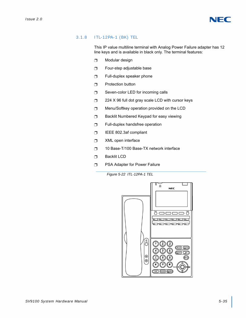
Issue 2.0
SV9100 System Hardware Manual 5-35
3.1.8 ITL-12PA-1 (BK) TEL
This IP value multiline terminal with Analog Power Failure adapter has 12 line keys and is available in black only. The terminal features:
Modular design
Four-step adjustable base
Full-duplex speaker phone
Protection button
Seven-color LED for incoming calls
224 X 96 full dot gray scale LCD with cursor keys
Menu/Softkey operation provided on the LCD
Backlit Numbered Keypad for easy viewing
Full-duplex handsfree operation
IEEE 802.3af compliant
XML open interface
10 Base-T/100 Base-TX network interface
Backlit LCD
PSA Adapter for Power Failure
Figure 5-22 ITL-12PA-1 TEL
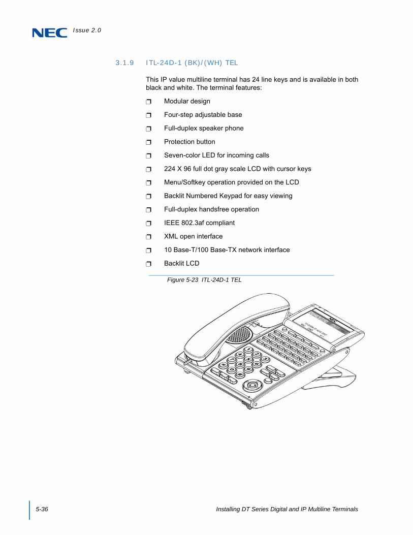
Issue 2.0
5-36 Installing DT Series Digital and IP Multiline Terminals
3.1.9 ITL-24D-1 (BK)/(WH) TEL
This IP value multiline terminal has 24 line keys and is available in both black and white. The terminal features:
Modular design
Four-step adjustable base
Full-duplex speaker phone
Protection button
Seven-color LED for incoming calls
224 X 96 full dot gray scale LCD with cursor keys
Menu/Softkey operation provided on the LCD
Backlit Numbered Keypad for easy viewing
Full-duplex handsfree operation
IEEE 802.3af compliant
XML open interface
10 Base-T/100 Base-TX network interface
Backlit LCD
Figure 5-23 ITL-24D-1 TEL

Issue 2.0
SV9100 System Hardware Manual 5-37
3.1.10 ITL-32D-1 (BK/WH) TEL
This IP value multiline terminal has 32 line keys (24 line keys plus an eight line key LK Unit) and is available in both black and white. The terminal features:
Modular design
Four-step adjustable base
Full-duplex speaker phone
Protection button
Seven-color LED for incoming calls
224 X 96 full dot gray scale LCD with cursor keys
Menu/Softkey operation provided on the LCD
Backlit Numbered Keypad for easy viewing
Full-duplex handsfree operation
IEEE 802.3af compliant
XML open interface
10 Base-T/100 Base-TX network interface
Backlit LCD
Figure 5-24 ITL-32D-1 TEL

Issue 2.0
5-38 Installing DT Series Digital and IP Multiline Terminals
3.1.11 ITL-320C-1 (BK) TEL/ITL-320C-2 (BK) TEL
This IP multiline terminal features a large color touch panel LCD and is available in black only. The terminal features:
Modular design
Four-step adjustable base
Full-duplex speaker phone
Protection button
Seven-color LED for incoming calls
Large color touch LCD
Menu/Softkey operation provided on the LCD
Backlit Numbered Keypad for easy viewing
Full-duplex handsfree operation
IEEE 802.3af compliant
XML open interface
10 Base-T/100 Base-TX network interface
Backlit LCD
Figure 5-25 ITL-320C-1 TEL/ITL-320C-2 TEL

Issue 2.0
SV9100 System Hardware Manual 5-39
3.2 DT800 Series IP Multiline Terminals
3.2.1 ITZ-8LD-3 (BK) TEL
This IP value multiline terminal has eight line keys with display and is available in black. The terminal features:
Modular design
Four-step adjustable base
Full-duplex hands-free operation
DESI-Less line key displays eight lines per page (four pages of eight lines available using scroll key)
Seven-color LED for incoming calls
Two 224 X 96 full dot gray scale LCDs with cursor keys
Backlit Numbered Keypad for easy viewing
Wideband handset
IEEE 802.3af compliant
XML open interface
10 Base-T/100 Base-TX network interface
Backlit LCD
Figure 5-26 ITZ-8LD-3 TEL

Issue 2.0
5-40 Installing DT Series Digital and IP Multiline Terminals
3.2.2 ITZ-12D-3 (BK)/(WH) TEL
This IP value multiline terminal has 12 line keys and is available in both black and white. The terminal features:
Modular design
Four-step adjustable base
Seven-color LED for incoming calls
224 X 96 full dot gray scale LCD with cursor keys
Backlit Numbered Keypad for easy viewing
10 Base-T/100 Base-TX network interface
12 Line buttons
Menu/Softkey operation provided on the LCD
Full-duplex handsfree operation
IEEE 802.3af compliant
XML open interface
Backlit LCD
Figure 5-27 ITZ-12D-3 TEL

Issue 2.0
SV9100 System Hardware Manual 5-41
3.2.3 ITZ-12/24CG-3 (BK)/(WH) TEL
This IP value multiline terminal has 12/24 line keys and is available in both black and white. The terminal features:
Modular design
Four-step adjustable base
Seven-color LED for incoming calls
Color LCD
Backlit Numbered Keypad for easy viewing
10 Base-T/100 Base-TX/1000 BASE-T network interface
12 Line buttons
XML Open Interface support
Full-duplex handsfree operation
IEEE 802.3af compliant
Menu/Soft key Operation
USB I/F
EHS I/F (with R2 F/W)
Figure 5-28 ITZ-12CG-3 TEL

Issue 2.0
5-42 Installing DT Series Digital and IP Multiline Terminals
3.2.4 ITZ-12/24DG-3 (BK)/(WH) TEL
This IP value multiline terminal has 12/24 line keys and is available in both black and white. The terminal features:
Modular design
Four-step adjustable base
Seven-color LED for incoming calls
Monochrome LCD
Backlit Numbered Keypad for easy viewing
10 Base-T/100 Base-TX/1000 BASE-T network interface
12 Line buttons
XML Open Interface support
Full-duplex handsfree operation
IEEE 802.3af compliant
Menu/Soft key Operation
USB I/F
EHS I/F (with R2 F/W)
Figure 5-29 ITZ-12DG-3 TEL

Issue 2.0
SV9100 System Hardware Manual 5-43
3.2.5 ITZ-24D-3 (BK)/(WH) TEL
This IP value multiline terminal has 24 line keys and is available in both black and white. The terminal features:
Modular design
Four-step adjustable base
Seven-color LED for incoming calls
224 X 96 full dot gray scale LCD with cursor keys
Backlit Numbered Keypad for easy viewing
10 Base-T/100 Base-TX network interface
24 Line buttons
Menu/Softkey operation provided on the LCD
Full-duplex handsfree operation
IEEE 802.3af compliant
XML open interface
Backlit LCD
Figure 5-30 ITZ-24D-3 TEL

Issue 2.0
5-44 Installing DT Series Digital and IP Multiline Terminals
3.2.6 ITZ-8LDG-3 (BK)/(WH) TEL
This IP value multiline terminal has eight line keys with display and is available in both black and white. The terminal features:
Modular design
Four-step adjustable base
Seven-color LED for incoming calls
Two 224 X 96 full dot gray scale LCDs with cursor keys
DESI-Less line key displays eight lines per page (four pages of eight lines available using scroll key)
Backlit Numbered Keypad for easy viewing
10 Base-T/100 Base-TX/1000 BASE-T network interface
Full-duplex handsfree operation
Wideband handset
IEEE 802.3af compliant
XML open interface
Backlit LCD
Figure 5-31 ITZ-8LDG-3 TEL
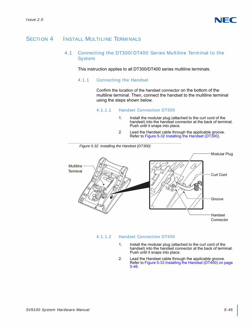
Issue 2.0
SV9100 System Hardware Manual 5-45
SECTION 4 INSTALL MULTILINE TERMINALS
4.1 Connecting the DT300/DT400 Series Multiline Terminal to the System
This instruction applies to all DT300/DT400 series multiline terminals.
4.1.1 Connecting the Handset
Confirm the location of the handset connector on the bottom of the multiline terminal. Then, connect the handset to the multiline terminal using the steps shown below.
4.1.1.1 Handset Connection DT300
1. Install the modular plug (attached to the curl cord of the handset) into the handset connector at the back of terminal. Push until it snaps into place.
2. Lead the Handset cable through the applicable groove. Refer to Figure 5-32 Installing the Handset (DT300).
4.1.1.2 Handset Connection DT400
1. Install the modular plug (attached to the curl cord of the handset) into the handset connector at the back of terminal. Push until it snaps into place.
2. Lead the Handset cable through the applicable groove. Refer to Figure 5-33 Installing the Handset (DT400) on page 5-46.
Figure 5-32 Installing the Handset (DT300)

Issue 2.0
5-46 Installing DT Series Digital and IP Multiline Terminals
4.1.2 Connecting the Line Cord
Confirm the location of the line connector on the bottom of the multiline terminal. Then, connect the line cord to the multiline terminal using the steps shown below.
4.1.2.1 Line Cord Connection DT300
1. Install the modular plug of the Line Cord into the Line Connector at the back of terminal. Push until it snaps into place. Refer to Figure 5-34 Installing the Line Cord (DT300).
Figure 5-33 Installing the Handset (DT400)
Figure 5-34 Installing the Line Cord (DT300)
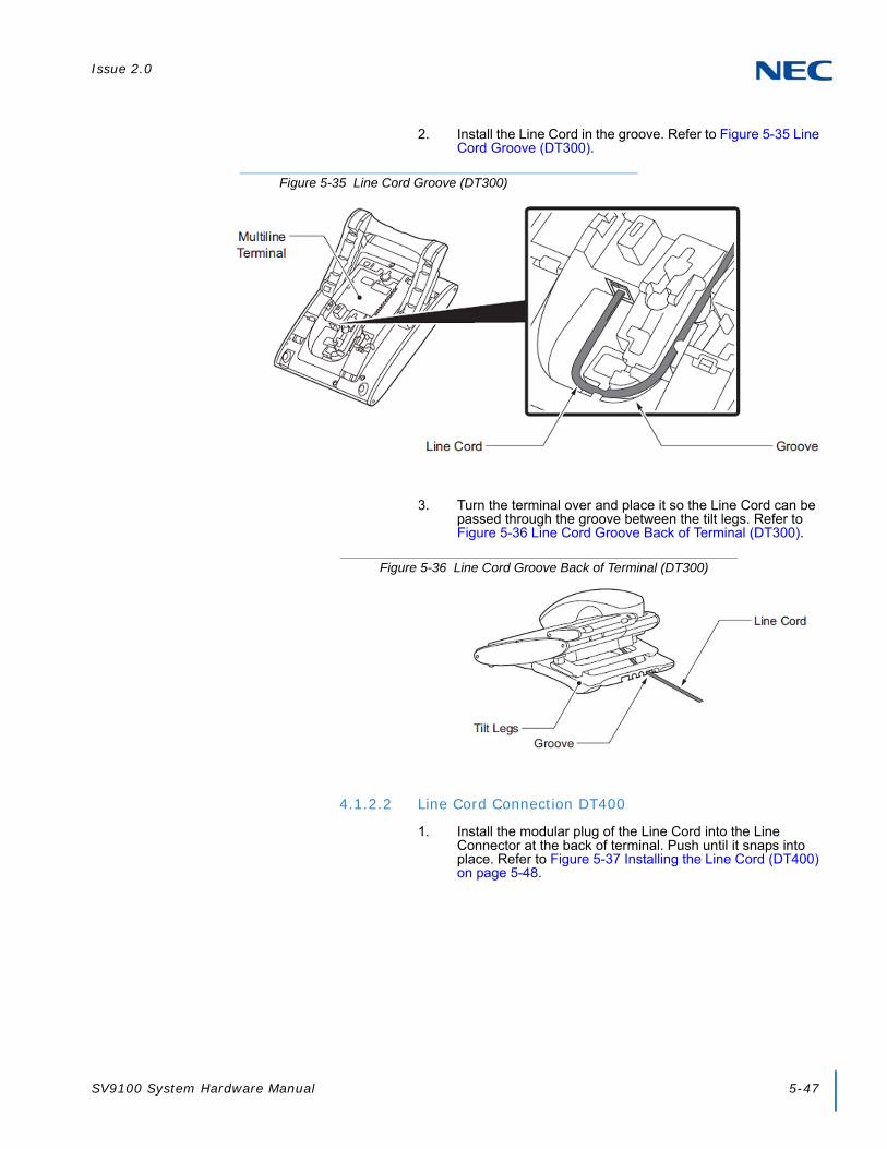
Issue 2.0
SV9100 System Hardware Manual 5-47
2. Install the Line Cord in the groove. Refer to Figure 5-35 Line Cord Groove (DT300).
3. Turn the terminal over and place it so the Line Cord can be passed through the groove between the tilt legs. Refer to Figure 5-36 Line Cord Groove Back of Terminal (DT300).
4.1.2.2 Line Cord Connection DT400
1. Install the modular plug of the Line Cord into the Line Connector at the back of terminal. Push until it snaps into place. Refer to Figure 5-37 Installing the Line Cord (DT400) on page 5-48.
Figure 5-35 Line Cord Groove (DT300)
Figure 5-36 Line Cord Groove Back of Terminal (DT300)

Issue 2.0
5-48 Installing DT Series Digital and IP Multiline Terminals
2. Install the Line Cord in the groove. Refer to Figure 5-38 Line Cord Groove (DT400).
3. Turn the terminal over and place it so the Line Cord can be passed through the groove between the tilt legs. Refer to Figure 5-36 Line Cord Groove Back of Terminal (DT300) on page 5-47.
Figure 5-37 Installing the Line Cord (DT400)
Figure 5-38 Line Cord Groove (DT400)

Issue 2.0
SV9100 System Hardware Manual 5-49
4.2 Applying Power to the DT700/DT800 Multiline Terminal
The DT700/DT800 series terminals support two different power sources:
AC-2R/AC-3R
Plug the optional AC-2R/AC-3R AC Adapter input Jack in the terminal base unit, and plug the 2-prong wall plug of the AC Adapter in a standard 120 Vac wall outlet.
In-Line Power/PoE (Power over Ethernet)
In-Line Power (sometimes called Power Over Ethernet) is a LAN technology that allows standard 10 Base-T/100 Base-TX data cables to pass electrical current from a power source to a requesting end device.
ITL Terminals
An AC-L Unit is required if using local power.
Figure 5-39 Line Cord Groove Back of Terminal (DT400)
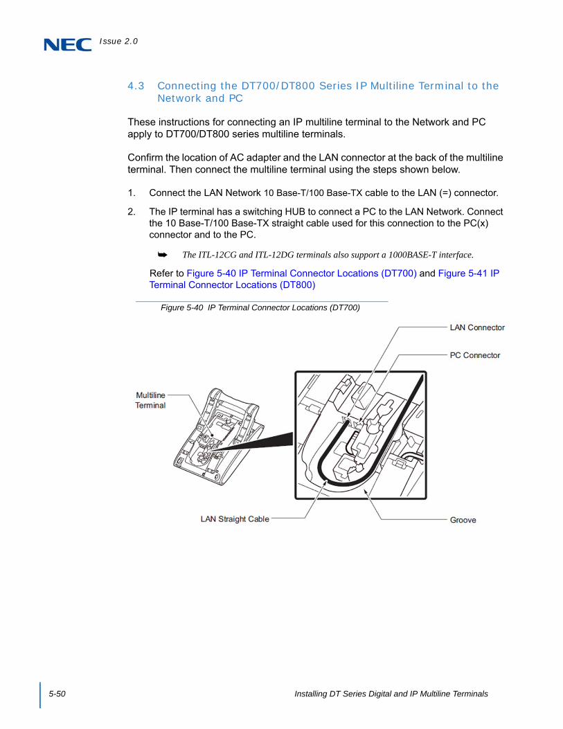
Issue 2.0
5-50 Installing DT Series Digital and IP Multiline Terminals
4.3 Connecting the DT700/DT800 Series IP Multiline Terminal to the Network and PC
These instructions for connecting an IP multiline terminal to the Network and PC apply to DT700/DT800 series multiline terminals.
Confirm the location of AC adapter and the LAN connector at the back of the multiline terminal. Then connect the multiline terminal using the steps shown below.
1. Connect the LAN Network 10 Base-T/100 Base-TX cable to the LAN (=) connector.
2. The IP terminal has a switching HUB to connect a PC to the LAN Network. Connect the 10 Base-T/100 Base-TX straight cable used for this connection to the PC(x) connector and to the PC.
The ITL-12CG and ITL-12DG terminals also support a 1000BASE-T interface.
Refer to Figure 5-40 IP Terminal Connector Locations (DT700) and Figure 5-41 IP Terminal Connector Locations (DT800)
Figure 5-40 IP Terminal Connector Locations (DT700)
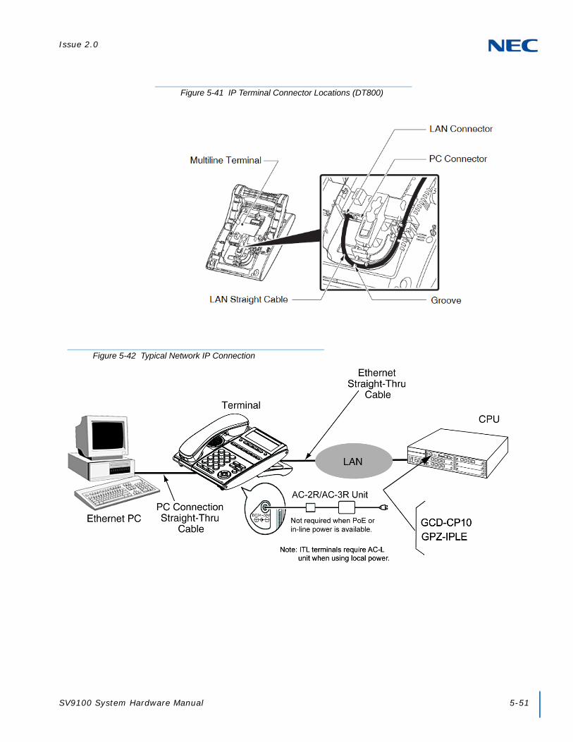
Issue 2.0
SV9100 System Hardware Manual 5-51
Figure 5-41 IP Terminal Connector Locations (DT800)
Figure 5-42 Typical Network IP Connection

Issue 2.0
5-52 Installing DT Series Digital and IP Multiline Terminals
4.4 Adjusting the LCD on the Multiline Terminal
DT series display multiline terminals have an adjustable Liquid Crystal Display (LCD). The LCD can be adjusted by pulling up or pushing down as desired.
4.5 Installing Line Key Kit (12LK-L KIT)
The 12LK-L KIT Provides 12 additional buttons to ITL or DTL multiline terminals. The 12LK-L KIT kit:
Mounts directly to top side of terminal
Supports Red and Green LED colors
4.5.1 Installing the 12LK-L KIT
1. Turn multiline terminal upside down.
Figure 5-43 Adjusting the LCD on a Multiline Terminal
Figure 5-44 12LK-L Kit
WARNING
To prevent possible damage to the 12LK-L KIT or the DTL/ITL multiline terminal during installation or removal, disconnect the line cord/LAN cable and theAC/DC adapter from the DTL/ITL multiline terminal.

Issue 2.0
SV9100 System Hardware Manual 5-53
Only one 12LK-L KIT can be attached to the DTL/ITL multiline terminal.
2. Pry the right side panel from the multiline terminal.
3. From the lower left or right corner, pry the Line Key Panel from the multiline terminal (refer to Figure 5-45 Removing the Line Key Panel on page 5-53).
4. Lift and remove the DESI sheet.
Figure 5-45 Removing the Line Key Panel
Line Key Panel

Issue 2.0
5-54 Installing DT Series Digital and IP Multiline Terminals
Figure 5-46 Removing the DESI Sheet
DESI Sheet

Issue 2.0
SV9100 System Hardware Manual 5-55
5. Press the right end of the Line Key placeholder and lift to remove (refer to Figure 5-47 Removing the Line Key Placeholder on page 5-55).
6. Install the 12LK-L KIT and slide until aligned with the Tab Hole.
Figure 5-47 Removing the Line Key Placeholder
Figure 5-48 Aligning the 12LK-L KIT
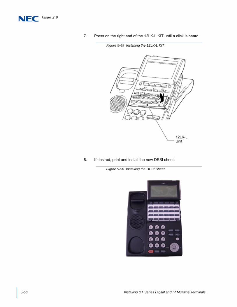
Issue 2.0
5-56 Installing DT Series Digital and IP Multiline Terminals
7. Press on the right end of the 12LK-L KIT until a click is heard.
8. If desired, print and install the new DESI sheet.
Figure 5-49 Installing the 12LK-L KIT
Figure 5-50 Installing the DESI Sheet

Issue 2.0
SV9100 System Hardware Manual 5-57
9. Install the supplied Line Key Panel (refer to Figure 5-51 Installing the Line Key Panel). A variety of colors is now available for the 12 and 24 button LK Panels (refer to Chapter 1, Table 1-10 SV9100 Optional Equipment List on page 1-13).
10. Install the side panel.
11. Connect the line cord/LAN cable and the AC/DC adapter to theDTL/ITL multiline terminal.
4.5.2 Configuring the Digital Telephone for the Correct Number of Line Keys
1. With the telephone not plugged in and the handset on-hook, press the 4 and 6 buttons on the numbered keypad and connect the telephone cable.
This places the telephone into Service Class Read/Write (R/W) mode. The Message Waiting (MW) LED should be On.
2. Press 1 to enter the Line Key Type mode.
The Message Waiting LED should flash.
Figure 5-51 Installing the Line Key Panel
Line Key Panel

Issue 2.0
5-58 Installing DT Series Digital and IP Multiline Terminals
3. Follow the directions below for the type of line key module installed:
4. Save to memory by pressing line key 2, 8, 14 or 20. The display changes back to the Service Class R/W mode and the Message Waiting (MW) LED is On Red.
5. Press Exit to return the telephone to idle.
4.5.3 Configuring the IP Telephone for the Correct Number of Line Keys
1. Press Menu, then 0 (Config) to enter the terminal program mode.
2. At the Login screen, enter the user name (default = ADMIN) and password (default = 6633222) and press the OK Softkey.
3. Press 3 for Maintenance Setting.
4. Press 4 for Adjust.
5. Press 2 for Key Kit Type.
6. Press the Up/Down key to select the Key Kit.
Table 5-12 Line Key Type
Line Key Type Push
2-Button 1
6-Button 2
8-Button 3
12-Button 4
24-Button 5
Table 5-13 Ten Key Kit Type
Ten Key Kit Entry Description
Kit1 Type A – Japan with cursor key
Kit2 Type A – US with cursor key
Kit3 Type B – US with cursor key
Kit4
Kit8 32 Line Key without cursor key
Kit9 Type A – Japan without cursor key
Kit10 Type A – US without cursor key
Kit11 Type B – US without cursor key
Kit12

Issue 2.0
SV9100 System Hardware Manual 5-59
7. Press Softkey 4 for Next.
8. Press the Up/Down key to select the Line Key kit.
By default, the correct line key kit for the keypad kit selected above is highlighted.
9. Press Softkey 4 for OK to complete.
10. Continue pressing Softkey 4 to exit (Exit-Exit-Save). The terminal resets automatically.
Table 5-14 Line Key Kit Type
Line Key Kit Entry Description
Kit12 Enhanced 12-Button
Kit24 Enhanced 24-Button
Kit32 Enhanced 32-Button
Kit8 DESI-Less
Kit6 Value 6-Button
Kit2 Value 2-Button
Kit0 IP-CTS

Issue 2.0
5-60 Installing DT Series Digital and IP Multiline Terminals
4.6 Installing the Directory Card on the Multiline Terminal
A directory card can be attached to DT300/DT700 Series multiline terminals. The directory card can be used to record often dialed numbers or other important information.
1. After recording the information on the lined insert, reinsert it between the plastic panels of the directory card. Attach the directory card to the directory card holder as illustrated in Figure 5-52 Attaching Directory Card to Directory Card Holder. The open end slides into the directory card holder.
2. Locate the two grooves on the top of the telephone as illustrated in Figure 5-53 Attaching Directory Card Holder to the Multiline Terminal. Push the directory card holder into the grooves on the multiline terminal until they snap into place.
To remove the directory card, press the two sides of the directory card holder inward until the tabs release and pull the holder out of the grooves.
Figure 5-52 Attaching Directory Card to Directory Card Holder
Directory Card
Directory Card Holder

Issue 2.0
SV9100 System Hardware Manual 5-61
4.7 Removal and Replacement of the Numbered Keypad
The Numbered Keypad (in black or white), is commonly delivered in the Business/Standard Layout configuration (refer to Figure 5-54 Standard Numbered Keypad) and can be easily removed and replaced.
Figure 5-53 Attaching Directory Card Holder to the Multiline Terminal
Figure 5-54 Standard Numbered Keypad

Issue 2.0
5-62 Installing DT Series Digital and IP Multiline Terminals
4.7.1 Removing the Numbered Keypad
1. Remove the Numbered Keypad Panel. (Refer to paragraph Figure 5-55 Remove Plastic Panels.)
2. Pull down on the tab and lift the Numbered Keypad away from the telephone to remove the existing button. Refer to Figure 5-56 Removing Numbered Keypad from DT300/DT700 Series Terminal.
WARNING
To prevent possible damage to the Numbered Keypad or the DTL/ITL multiline terminal during installation or removal, disconnect the line cord/LAN cable and the AC/DC adapter from the DTL/ITL multiline terminal.
Figure 5-55 Remove Plastic Panels
Line Key Panel
Numbered Keypad Panel
Desi Printer Sheet
Figure 5-56 Removing Numbered Keypad from DT300/DT700 Series Terminal

Issue 2.0
SV9100 System Hardware Manual 5-63
4.7.2 Installing the Numbered Keypad
1. Slide the replacement numbered keypad into the grooves located on the inside of the telephone, then press down on the keypad to snap it into place. Refer to Figure 5-57 Install New Numbered Keypad into DT300/DT700 Series Terminal.
2. Install the Numbered Keypad Panel on the multiline terminal. Refer to Figure 5-58 Install Plastic Panels.
Figure 5-57 Install New Numbered Keypad into DT300/DT700 Series Terminal
Figure 5-58 Install Plastic Panels
Desi Printer Sheet
Line Key Panel
Numbered Keypad Panel

Issue 2.0
5-64 Installing DT Series Digital and IP Multiline Terminals
4.8 Removal and Replacement of the BS( )-L Kit (Ten Key Kit)
The Business BS( )-L Kit (in black or white), is commonly delivered with the UNIVERGE SV9100 multiline terminal. If required, the BS( )-L Kit can be removed and replaced on the DT300/DT700 Series multiline terminal.
The Retro BS( )-L Kit is an optional kit available to be used with the IPK II and IPS terminals.
4.8.1 Remove the BS( )-L Kit
1. Pry the right side panel from the multiline terminal (refer to Figure 5-59 Remove Plastic Panels).
2. Remove the Numbered Keypad panel. (Refer to paragraph Figure 5-60 Remove the Ten Key Kit on page 5-65.)
Figure 5-59 Remove Plastic Panels
Line Key Panel
Numbered Keypad Panel
Desi Printer Sheet
Side Panel

Issue 2.0
SV9100 System Hardware Manual 5-65
3. Carefully pry and lift the Ten Key kit from the multiline terminal.
4.8.2 Install the BS( )-L Kit
1. Slide replacement Ten Key kit into position. Tabs of kit fit into holes on the multiline terminal.
Figure 5-60 Remove the Ten Key Kit
Figure 5-61 Install the Ten Key Kit
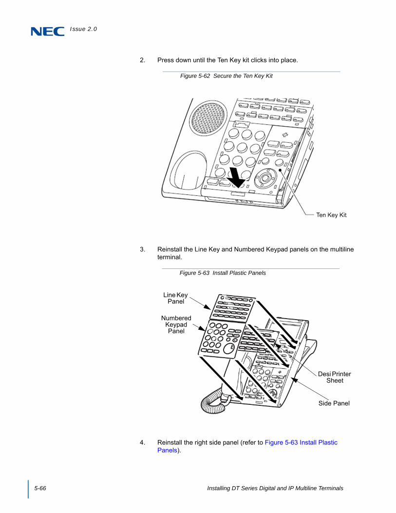
Issue 2.0
5-66 Installing DT Series Digital and IP Multiline Terminals
2. Press down until the Ten Key kit clicks into place.
3. Reinstall the Line Key and Numbered Keypad panels on the multiline terminal.
4. Reinstall the right side panel (refer to Figure 5-63 Install Plastic Panels).
Figure 5-62 Secure the Ten Key Kit
Figure 5-63 Install Plastic Panels
Desi Printer Sheet
Line Key Panel
Numbered Keypad Panel
Side Panel
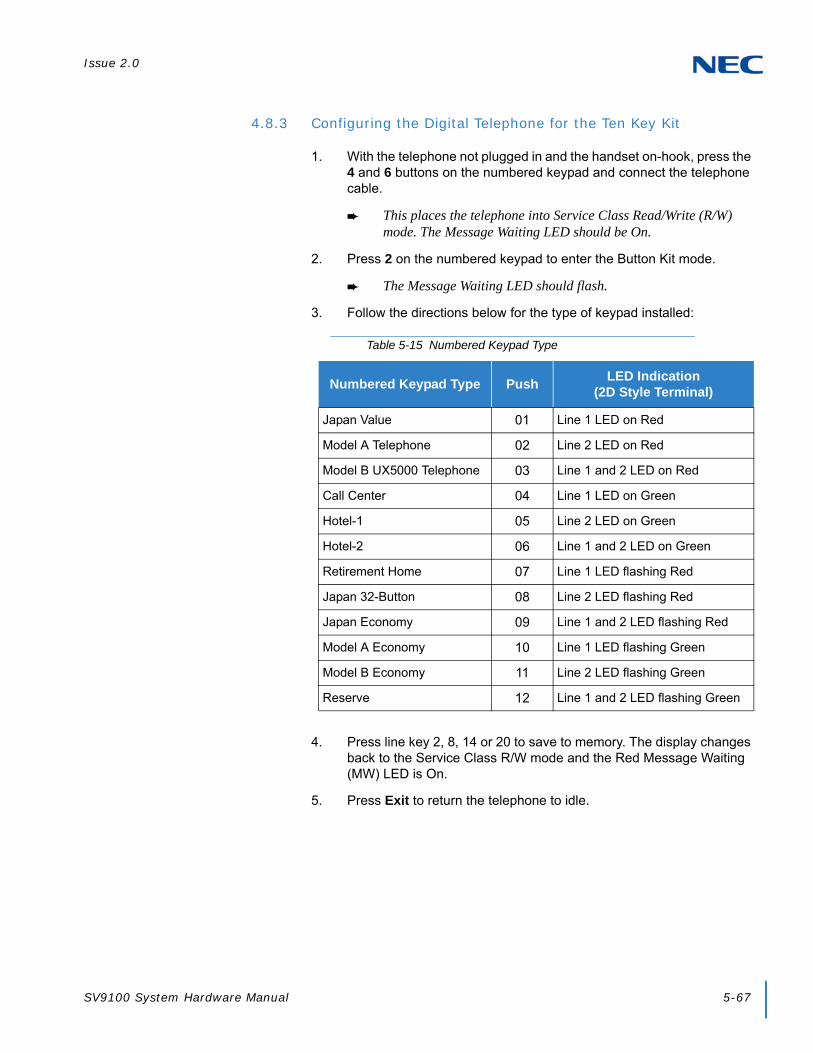
Issue 2.0
SV9100 System Hardware Manual 5-67
4.8.3 Configuring the Digital Telephone for the Ten Key Kit
1. With the telephone not plugged in and the handset on-hook, press the 4 and 6 buttons on the numbered keypad and connect the telephone cable.
This places the telephone into Service Class Read/Write (R/W) mode. The Message Waiting LED should be On.
2. Press 2 on the numbered keypad to enter the Button Kit mode.
The Message Waiting LED should flash.
3. Follow the directions below for the type of keypad installed:
4. Press line key 2, 8, 14 or 20 to save to memory. The display changes back to the Service Class R/W mode and the Red Message Waiting (MW) LED is On.
5. Press Exit to return the telephone to idle.
Table 5-15 Numbered Keypad Type
Numbered Keypad Type PushLED Indication
(2D Style Terminal)
Japan Value 01 Line 1 LED on Red
Model A Telephone 02 Line 2 LED on Red
Model B UX5000 Telephone 03 Line 1 and 2 LED on Red
Call Center 04 Line 1 LED on Green
Hotel-1 05 Line 2 LED on Green
Hotel-2 06 Line 1 and 2 LED on Green
Retirement Home 07 Line 1 LED flashing Red
Japan 32-Button 08 Line 2 LED flashing Red
Japan Economy 09 Line 1 and 2 LED flashing Red
Model A Economy 10 Line 1 LED flashing Green
Model B Economy 11 Line 2 LED flashing Green
Reserve 12 Line 1 and 2 LED flashing Green
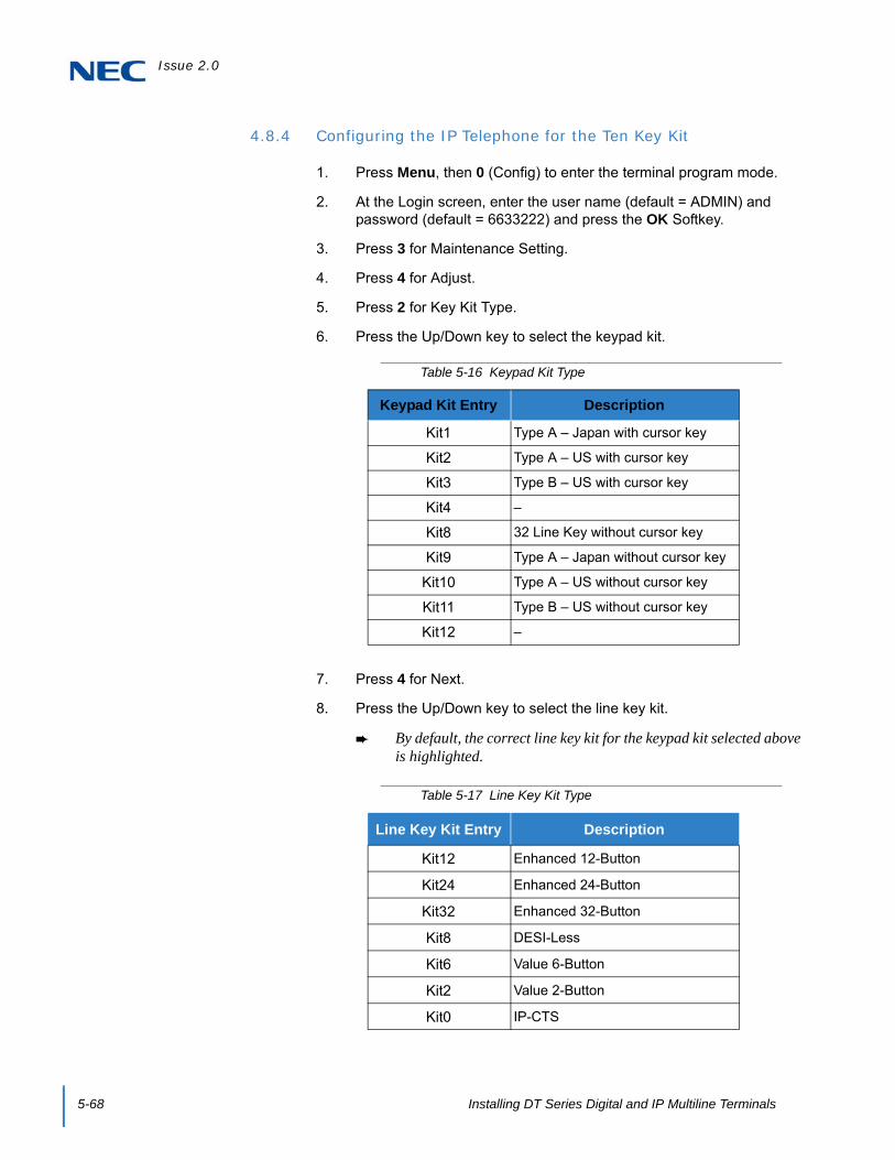
Issue 2.0
5-68 Installing DT Series Digital and IP Multiline Terminals
4.8.4 Configuring the IP Telephone for the Ten Key Kit
1. Press Menu, then 0 (Config) to enter the terminal program mode.
2. At the Login screen, enter the user name (default = ADMIN) and password (default = 6633222) and press the OK Softkey.
3. Press 3 for Maintenance Setting.
4. Press 4 for Adjust.
5. Press 2 for Key Kit Type.
6. Press the Up/Down key to select the keypad kit.
7. Press 4 for Next.
8. Press the Up/Down key to select the line key kit.
By default, the correct line key kit for the keypad kit selected above is highlighted.
Table 5-16 Keypad Kit Type
Keypad Kit Entry Description
Kit1 Type A – Japan with cursor key
Kit2 Type A – US with cursor key
Kit3 Type B – US with cursor key
Kit4 –
Kit8 32 Line Key without cursor key
Kit9 Type A – Japan without cursor key
Kit10 Type A – US without cursor key
Kit11 Type B – US without cursor key
Kit12 –
Table 5-17 Line Key Kit Type
Line Key Kit Entry Description
Kit12 Enhanced 12-Button
Kit24 Enhanced 24-Button
Kit32 Enhanced 32-Button
Kit8 DESI-Less
Kit6 Value 6-Button
Kit2 Value 2-Button
Kit0 IP-CTS
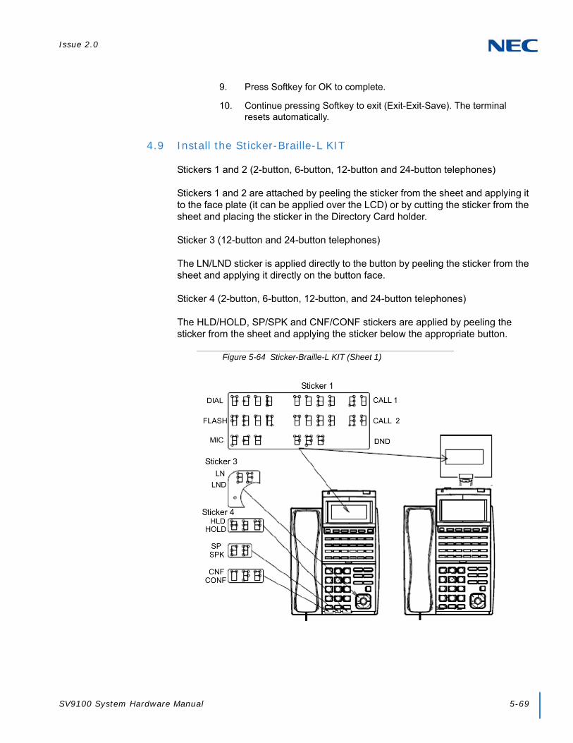
Issue 2.0
SV9100 System Hardware Manual 5-69
9. Press Softkey for OK to complete.
10. Continue pressing Softkey to exit (Exit-Exit-Save). The terminal resets automatically.
4.9 Install the Sticker-Braille-L KIT
Stickers 1 and 2 (2-button, 6-button, 12-button and 24-button telephones)
Stickers 1 and 2 are attached by peeling the sticker from the sheet and applying it to the face plate (it can be applied over the LCD) or by cutting the sticker from the sheet and placing the sticker in the Directory Card holder.
Sticker 3 (12-button and 24-button telephones)
The LN/LND sticker is applied directly to the button by peeling the sticker from the sheet and applying it directly on the button face.
Sticker 4 (2-button, 6-button, 12-button, and 24-button telephones)
The HLD/HOLD, SP/SPK and CNF/CONF stickers are applied by peeling the sticker from the sheet and applying the sticker below the appropriate button.
Figure 5-64 Sticker-Braille-L KIT (Sheet 1)

Issue 2.0
5-70 Installing DT Series Digital and IP Multiline Terminals
Figure 5-65 Sticker-Braille-L KIT (Sheet 2)

Issue 2.0
SV9100 System Hardware Manual 5-71
4.10 Adjusting the Height on the Multiline Terminal
The height of the DT series multiline terminals can be adjusted by moving the legs attached to the bottom of the terminal.
1. Turn telephone over (button side down).
2. Adjust legs to desired height (refer to Figure 5-66 Adjust Height of DT Series Terminal).
3. Turn telephone over (button side up).
Figure 5-66 Adjust Height of DT Series Terminal

Issue 2.0
5-72 Installing DT Series Digital and IP Multiline Terminals
4.11 Removing or Installing the Tilt Legs on the Multiline Terminal
The Tilt Legs can be removed or installed on the DT series multiline terminal.
4.11.1 Remove Tilt Legs
1. Place the telephone on a flat surface (button side down).
2. Separate the Tilt Legs and place them flat against the telephone. Refer to Figure 5-67 Separating the Tilt Legs.
3. Push downward (two arrows) and slide downward (refer to Figure 5-68 Removing Tilt Legs from Multiline Terminal).
4. Lift and remove the Tilt Legs.
Figure 5-67 Separating the Tilt Legs
Figure 5-68 Removing Tilt Legs from Multiline Terminal

Issue 2.0
SV9100 System Hardware Manual 5-73
4.11.2 Install Tilt Legs
1. Place the telephone on a flat surface (button side down).
2. Lay the adjustable Tilt legs on top of the telephone. Refer to Figure 5-69 Attach Tilt Legs to DT Series Terminal.
3. Push the Tilt Legs upward until they snap into place.
4. Lift both ends of Tilt Legs until they come together (refer to Figure 5-70 Connecting the Tilt Legs on page 5-74).
Figure 5-69 Attach Tilt Legs to DT Series Terminal

Issue 2.0
5-74 Installing DT Series Digital and IP Multiline Terminals
5. Snap legs together and adjust to desired height. Refer to Figure 5-71 Adjust Height of DT Series Terminal.
Figure 5-70 Connecting the Tilt Legs
Figure 5-71 Adjust Height of DT Series Terminal

Issue 2.0
SV9100 System Hardware Manual 5-75
4.12 Wall Mounting the Multiline Terminal
You can wall mount a DT series multiline terminal using the base cover or an optional wall mount unit. A wall mount unit must be used if adapters are installed on the multiline terminal.
When optional adapters are used, the multiline terminal must be installed on the wall using the WM-L UNIT (refer to 5.2.8 WM-L UNIT on page 5-98).
4.12.1 Wall Mounting a Multiline Terminal using the Base Plate
4.12.1.1 Adjusting the Hanger Hook
1. Remove the hook from the unit.
2. Turn the hook with the tab toward the top.
3. Slide the hook until it glides into position forming the hanger hook for the handset.
Figure 5-72 Removing the Hanger Hook on a DT Series Terminal
Hanger Hook
Figure 5-73 Sliding the Hanger Hook into Position

Issue 2.0
5-76 Installing DT Series Digital and IP Multiline Terminals
4.12.1.2 Wall Mounting the Multiline Terminal
1. Plug line cord in the wall receptacle. Leave about eight inches of cord and bundle the rest as shown in Figure 5-74 Bundling the Line Cord.
2. Ensure the Tilt Legs are in the flat (unused position).
3. Plug the line cord into the multiline terminal as illustrated in Figure 5-75 Plugging in Line Cord.
4. Align the two holes on the back of the multiline terminal with the two screws on the wall plate and slide downward (refer to Figure 5-76 Mount Multiline Terminal Wall on Wall Plate on page 5-77).
Figure 5-74 Bundling the Line Cord
Figure 5-75 Plugging in Line Cord

Issue 2.0
SV9100 System Hardware Manual 5-77
5. Push spare line cord behind the multiline terminal.
4.12.1.3 Removing the Multiline Terminal from the Wall Mounted Base Plate.
To remove the multiline terminal, push up on the terminal until it comes loose.
Figure 5-76 Mount Multiline Terminal Wall on Wall Plate
Figure 5-77 Removing the Multiline Terminal

Issue 2.0
5-78 Installing DT Series Digital and IP Multiline Terminals
4.12.1.4 Wall Mounting the Base on a Wall Plate
1. Locate the screw holes on the base and hang the cover over the screws on the wall plate as illustrated in Figure 5-78 Wall Mounting Base on Wall Plate.
2. Hang the multiline terminal on the base.
Because of variation in wall plates, this method is not recommended.
Figure 5-78 Wall Mounting Base on Wall Plate
Figure 5-79 Wall Mounted Multiline Terminal

Issue 2.0
SV9100 System Hardware Manual 5-79
SECTION 5 MULTILINE TERMINALS OPTIONAL EQUIPMENT
5.1 DT Series Terminal Options
The following charts provide a quick overview of the options available with the DT/IT Series terminals for UNIVERGE SV9100.
Table 5-18 Connectivity of Options (DT300/DT700)
Terminal Options
IP Terminals Digital Terminals
SophisticatedITL-320C-1 TEL
ValueITL-8LD-1
ITL-12D-1 ITL-12CG-3 ITL-12DG-3 ITL-24D-1 ITL-
32D-1
EconomyITL-2E-1 ITL-
6DE-1ITL-8LDE-1
ValueDTL-8LD-1 DTL-12D-1 DTL-24D-1 DTL-32D-1
EconomyDTL-2E-1
DTL-6DE-1DTL-12E-1
Key Kit
Ten Key Kit
12LK Kit N/A (Built in) (Except 8LD-1 Unit)
N/A (Except 8LD-1 Unit)
N/A
8LK Unit N/A N/A
EHS
(Except 32D-1 Unit)
N/A
(Except 32D-1 Unit)
N/A
Common
ADA:Analog Recording Adapter
N/A N/A
PSA:PSTN Adapter for analog
N/A N/A
DSS:60-Button DSS Console
N/A Connect to Digital Port on KTS
Digital
APR:Analog Port adapter with Ringer
N/A
DESI-Less LK/LCD Unit (Except8LD-1 Unit)
N/A
Backlit LCD (Except8LD-1 Unit)
N/A
IP
DESI-Less LK/LCD Unit N/A (Built in) (ExceptITL-12CG-3 ITL-12DG-3)
N/A N/A

Issue 2.0
5-80 Installing DT Series Digital and IP Multiline Terminals
5.2 DT Series Optional Terminal Equipment
5.2.1 8LK-L UNIT (BK/WH)
Provides eight additional line keys to DT series terminals (except Economy). The unit features:
Mounts directly to right side of terminal
Table 5-19 Connectivity of Options (DT400/DT800)
Terminal Options
IP Terminals Digital Terminals
ValueITZ-8LD-3
ITZ-8LDG-3 ITZ-12D-3 ITZ-24D-3
ITZ-12CG-3 ITZ-12DG-3
ValueDTZ-8LD-3 DTZ-12D-3 DTZ-24D-3
EconomyDTZ-2E-3
DTZ-6DE-3
Key Kit
Ten Key Kit
12LK Kit ITZ-12CG/12DG Only (Except
8LD-3 Unit)
N/A
8LK Unit N/A
Common
ADA:Analog Recording Adapter
N/A
DSS:60-Button DSS Console
Connect to Digital Port on KTS
DigitalAPR:Analog Port adapter with Ringer
N/A

Issue 2.0
SV9100 System Hardware Manual 5-81
Supports Red and Green LED colors
5.2.1.1 Installing the 8LK-L UNIT
1. Remove both plastic panels from the front of the multiline terminal.
2. Turn multiline terminal upside down.
Only one 8LK-L UNIT can be attached to the DT Series multiline terminal.
3. Pry the side panel from the multiline terminal.
4. Return the multiline terminal to the buttons side up position.
5. Fit the projections on the side of the 8LK-L UNIT into the guide holes on the side of the multiline terminal.
Figure 5-80 8LK-L UNIT
WARNING
To prevent possible damage to the 8LK-L UNIT or the DT Series multiline terminal during installation or removal, disconnect the linecord/LAN cable and the AC/DC adapter from the DT Series multiline terminal.
Figure 5-81 Remove Side Panel from Multiline Terminal
Side Panel

Issue 2.0
5-82 Installing DT Series Digital and IP Multiline Terminals
6. Secure the 8LK-L UNIT with the two screws provided.
7. Turn the multiline terminal upside down.
8. Open the small door covering the side option connectors by pulling the cover handle to the front.
9. Connect the cable from the 8LK-L UNIT to the side option connector (see Figure 5-83 Install the 8LK-L UNIT Cable) on the multiline terminal and close the cover.
10. Attach the side panel to the side of the 8LK-L UNIT.
11. Return the multiline terminal to the buttons side up.
12. Complete the installation by reattaching both plastic panels to the front of the multiline terminal.
Figure 5-82 Securing the 8LK-L UNIT with Screws
Figure 5-83 Install the 8LK-L UNIT Cable
Telephone Connection Cable Side Option
Connector
Cover

Issue 2.0
SV9100 System Hardware Manual 5-83
5.2.2 8LKD (LD)-L UNIT (BK/WH)
Provides eight additional line keys to DT300 Series (DTL) terminals. The unit features:
Mounts directly to top of terminal
Supports Desi-Less 2 LCD panels
Eight line keys by four pages
5.2.2.1 Installing the 8LKD (LD)-L UNIT
1. Turn multiline terminal upside down.
Only one 8LKD (LD)-L UNIT can be attached to the DTL multiline terminal.
Figure 5-84 8LKD (LD)-L UNIT
WARNING
To prevent possible damage to the 8LKD (LD)-L UNIT or the DTL multiline terminal during installation or removal, disconnect the linecord/LAN cable and the AC/DC adapter from the DTL multiline terminal.

Issue 2.0
5-84 Installing DT Series Digital and IP Multiline Terminals
2. Pry the side panel from the multiline terminal.
3. Remove the screw (refer to Figure 5-85 Remove Side Panel from Multiline Terminal on page 5-84).
4. Carefully, return the multiline terminal to the buttons side up.
5. Remove the Softkeys and Line Key kit from the telephone.
6. Gently lift the small black bar on the ribbon cable connector (refer to Figure 5-86 Ribbon Cable Connector).
Figure 5-85 Remove Side Panel from Multiline Terminal
Side Panel
Screw
Figure 5-86 Ribbon Cable Connector
Lift Here

Issue 2.0
SV9100 System Hardware Manual 5-85
7. Plug ribbon cable on back of 8LKD (LD)-L UNIT into connector until pressure is felt.
8. Press down on the black bar to lock the cable into place (refer to Figure 5-87 Ribbon Cable Installed on page 5-85).
9. Align the projections on the bottom of the 8LKD (LD)-L UNIT with the guide holes on top of the multiline terminal.
10. Slide the 8LKD (LD)-L UNIT toward the keypad buttons until snug (refer to Figure 5-88 8LKD (LD)-L UNIT Installed).
Figure 5-87 Ribbon Cable Installed
Projection(One Each Side)
Guide
Guide
Figure 5-88 8LKD (LD)-L UNIT Installed

Issue 2.0
5-86 Installing DT Series Digital and IP Multiline Terminals
11. Holding the LCD in place, turn the multiline terminal button side down.
12. Install the screw (refer to Figure 5-89 Install Screw).
13. Attach the side panel to the side of the 8LKD (LD)-L UNIT (refer to Figure 5-95 Install Screw on page 5-90).
14. Return the multiline terminal to the buttons side up.
15. Connect the line cord/LAN cable and the AC/DC adapter to the DTL multiline terminal.
Figure 5-89 Install Screw
Side Panel
Screw

Issue 2.0
SV9100 System Hardware Manual 5-87
5.2.3 8LKI (LD)-L UNIT (BK/WH)
Provides eight additional line keys to DT700 Series (ITL) DESI-Less terminals. The unit features:
Mounts directly to top of terminal
Supports Desi-Less 2 LCD panels
Eight line keys by four pages
5.2.3.1 Installing the 8LKI (LD)-L UNIT
1. Turn multiline terminal upside down.
Only one 8LKI (LD)-L UNIT can be attached to the ITL multiline terminal.
Figure 5-90 8LKI (LD)-L UNIT
WARNING
To prevent possible damage to the 8LKI (LD)-L UNIT or the ITL multiline terminal during installation or removal, disconnect the linecord/LAN cable and the AC/DC adapter from the ITL multiline terminal.
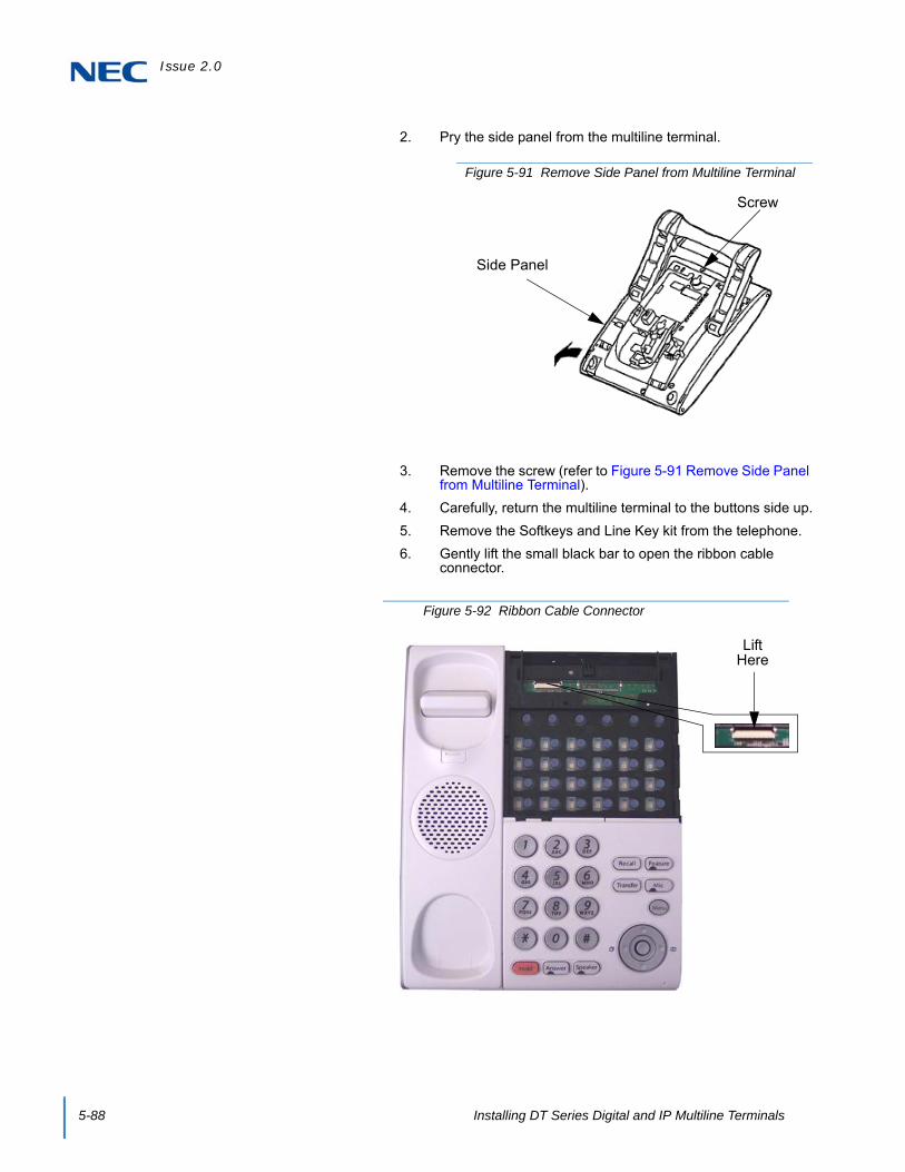
Issue 2.0
5-88 Installing DT Series Digital and IP Multiline Terminals
2. Pry the side panel from the multiline terminal.
3. Remove the screw (refer to Figure 5-91 Remove Side Panel from Multiline Terminal).
4. Carefully, return the multiline terminal to the buttons side up.
5. Remove the Softkeys and Line Key kit from the telephone.
6. Gently lift the small black bar to open the ribbon cable connector.
Figure 5-91 Remove Side Panel from Multiline Terminal
Side Panel
Screw
Figure 5-92 Ribbon Cable Connector
Lift Here

Issue 2.0
SV9100 System Hardware Manual 5-89
7. Plug ribbon cable on back of 8LKI (LD)-L UNIT into connector (metal side down) until pressure is felt.
8. Press down on the black bar to lock the cable into place (refer to Figure 5-93 Ribbon Cable Installed).
9. Align the projections on the bottom of the 8LKI (LD)-L UNIT with the guide holes on top of the multiline terminal (refer to Figure 5-93 Ribbon Cable Installed on page 5-89).
10. Slide the 8LKI (LD)-L UNIT toward the keypad buttons until snug (refer to Figure 5-94 8LKI (LD)-L UNIT Installed).
Figure 5-93 Ribbon Cable Installed
Projection(One Each Side)
Guide
Guide
Figure 5-94 8LKI (LD)-L UNIT Installed

Issue 2.0
5-90 Installing DT Series Digital and IP Multiline Terminals
11. Holding the LCD in place, turn the multiline terminal button side down.
12. Install screw (refer to Figure 5-95 Install Screw).
13. Attach the side panel to the side of the 8LKI (LD)-L UNIT (refer to Figure 5-95 Install Screw).
14. Return the multiline terminal to the buttons side up.
15. Connect the line cord/LAN cable and the AC/DC adapter to the ITL multiline terminal.
Figure 5-95 Install Screw
Side Panel
Screw

Issue 2.0
SV9100 System Hardware Manual 5-91
5.2.4 DCL-60-1/DCZ-60-2 CONSOLE (BK/WH)
The Attendant Console has 60 programmable line keys and is available in black or white. The unit features:
60 programmable Direct Station Selection (DSS) keys (refer to system user guides)
Supported on ITL or DTL modular terminals
Green and Red LEDs
The DSS Console gives a multiline terminal user a Busy Lamp Field (BLF) and one-button access to extensions, trunks and system features. The 60-Button DSS Console provides an additional 60 programmable keys. The page switching key allows a maximum of 120 keys. There are two pages of 54 programmable keys and six fixed keys.
Keep the following in mind when installing DSS Consoles:
A 60-Button DSS Console requires a separate digital station port when pairing with a digital multiline terminal. For IP terminals, the console is connected to the side option slot using a special cable.
Figure 5-96 DCL-60-1/DCZ-60-2 CONSOLE

Issue 2.0
5-92 Installing DT Series Digital and IP Multiline Terminals
5.2.4.1 Installing the DCL-60-1/DCZ-60-2 CONSOLE
1. Remove both plastic panels from the front of the multiline terminal.
2. Turn multiline terminal upside down.
Only one DCL-60-1/DCZ-60-2 CONSOLE can be attached to the DT Series multiline terminal.
3. Pry the side panel from the multiline terminal.
4. Turn the multiline terminal button side up.
5. Fit the projections of the supplied bracket into the side of the multiline terminal.
WARNING
To prevent possible damage to the DCL-60-1/DCZ-60-2 CONSOLE or the DT Series multiline terminal during installation or removal, disconnect the line cord/LAN cable and the AC/DC adapter from the DTL/ITL multiline terminal
TIP
If a “Digital Port Connection” is used, one telephone can support a maximum of 32 DSS Consoles.
If connected to an IP phone as a side option, a maximum of one DSS Console is supported per telephone.
Figure 5-97 Remove Side Panel from Multiline Terminal
Side Panel

Issue 2.0
SV9100 System Hardware Manual 5-93
6. Attach the bracket with three supplied screws.
7. Carefully push the Serial cable into the Serial Cable Groove (DT700/DT800 only).
8. Using the guides, slide the DCL-60-1/DCZ-60-2 CONSOLE onto the installed bracket (refer to Figure 5-99 Press Serial Cable into Groove).
Figure 5-98 Secure Bracket to Multiline Terminal with Screws
Screws
Figure 5-99 Press Serial Cable into Groove

Issue 2.0
5-94 Installing DT Series Digital and IP Multiline Terminals
9. Secure the DCL-60-1/DCZ-60-2 CONSOLE to the bracket with the two screws provided.
10. Open the small door covering the side option connectors by pulling the cover latch toward you (refer to Figure 5-101 Serial Cable Installed, ITL, DT700 only).
11. Connect the cable from the DCL-60-1/DCZ-60-2 CONSOLE to the Side Option Connector on the multiline terminal and close the cover (DT700/DT800 only).
12. Set the tilt leg on the multiline terminal to the desired height.
Figure 5-100 Securing the DCL-60-1/DCZ-60-2 CONSOLE with Screws
Figure 5-101 Serial Cable Installed
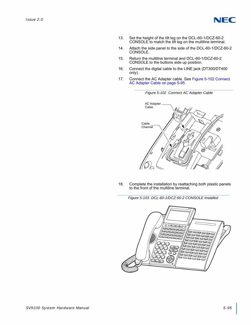
Issue 2.0
SV9100 System Hardware Manual 5-95
13. Set the height of the tilt leg on the DCL-60-1/DCZ-60-2 CONSOLE to match the tilt leg on the multiline terminal.
14. Attach the side panel to the side of the DCL-60-1/DCZ-60-2 CONSOLE.
15. Return the multiline terminal and DCL-60-1/DCZ-60-2 CONSOLE to the buttons side up position.
16. Connect the digital cable to the LINE jack (DT300/DT400 only).
17. Connect the AC Adapter cable. See Figure 5-102 Connect AC Adapter Cable on page 5-95.
18. Complete the installation by reattaching both plastic panels to the front of the multiline terminal.
Figure 5-102 Connect AC Adapter Cable
Figure 5-103 DCL-60-1/DCZ-60-2 CONSOLE Installed

Issue 2.0
5-96 Installing DT Series Digital and IP Multiline Terminals
5.2.5 LCD (BL)-L UNIT (BK/WH)
The LCD (BL)-L UNIT is an optional LCD unit for modular terminals and supports the backlit LCD feature (DT300 Series only).
5.2.6 LCD (BL)-Z UNIT (BK/WH)
The LCD (BL)-Z UNIT is an optional LCD unit for modular terminals and supports the backlit LCD feature (DT400 Series only).
Figure 5-104 LCD (BL)-L UNIT
Figure 5-105 LCD (BL)-Z UNIT

Issue 2.0
SV9100 System Hardware Manual 5-97
5.2.7 PANEL( )-L UNIT
Optional plastic color side panels allow users to customize the ITL/DTL terminals. A variety colors are available for the Base (all), VLCD (Value LCD) and SLCD (Sophi LCD) terminals (refer to Chapter 1, Table 1-10 SV9100 Optional Equipment List on page 1-13).
Right and Left side panels are not interchangeable.
Figure 5-106 PANEL( )-L UNIT
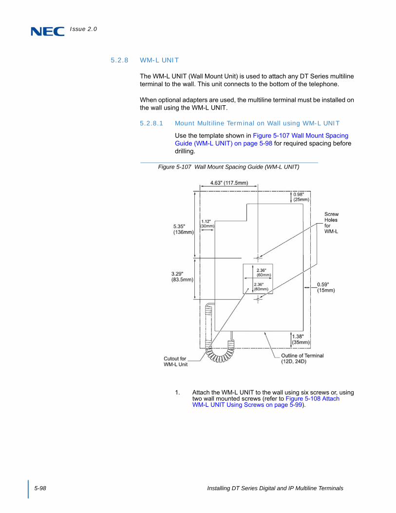
Issue 2.0
5-98 Installing DT Series Digital and IP Multiline Terminals
5.2.8 WM-L UNIT
The WM-L UNIT (Wall Mount Unit) is used to attach any DT Series multiline terminal to the wall. This unit connects to the bottom of the telephone.
When optional adapters are used, the multiline terminal must be installed on the wall using the WM-L UNIT.
5.2.8.1 Mount Multiline Terminal on Wall using WM-L UNIT
Use the template shown in Figure 5-107 Wall Mount Spacing Guide (WM-L UNIT) on page 5-98 for required spacing before drilling.
1. Attach the WM-L UNIT to the wall using six screws or, using two wall mounted screws (refer to Figure 5-108 Attach WM-L UNIT Using Screws on page 5-99).
Figure 5-107 Wall Mount Spacing Guide (WM-L UNIT)

Issue 2.0
SV9100 System Hardware Manual 5-99
2. Plug one end of the line cord into the wall receptacle. Leave about eight inches of cord and bundle the rest.
3. Plug the opposite end of the line cord into the multiline terminal as illustrated in Figure 5-109 Plugging in Line Cord.
Figure 5-108 Attach WM-L UNIT Using Screws
Figure 5-109 Plugging in Line Cord

Issue 2.0
5-100 Installing DT Series Digital and IP Multiline Terminals
4. Align the four cutouts on the bottom of the multiline terminal (refer to Figure 5-110 Cutouts for WM-L UNIT) with the tabs on the WM-L UNIT (refer to Figure 5-111 WM-L UNIT Tabs).
Figure 5-110 Cutouts for WM-L UNIT
Figure 5-111 WM-L UNIT Tabs
Tabs Tabs

Issue 2.0
SV9100 System Hardware Manual 5-101
5. Push down until the multiline terminal snaps into place (refer to Figure 5-112 WM-L UNIT Installed).
6. To release the multiline terminal from the WM-L UNIT, press the release button and push the telephone up (refer to Figure 5-113 WM-L UNIT Release Button).
Figure 5-112 WM-L UNIT Installed
Figure 5-113 WM-L UNIT Release Button

Issue 2.0
5-102 Installing DT Series Digital and IP Multiline Terminals
5.2.8.2 Mount Multiline Terminal on Wall Plate using WM-L UNIT
1. Locate the screw holes on the base and hang the cover over the screws on the wall plate as illustrated in Figure 5-114 Attach WM-L UNIT to Wall Plate.
Because of variation in wall plates, this method is not recommended.
2. Plug one end of the line cord into the wall receptacle. Leave about eight inches of cord and bundle the rest.
3. Plug the opposite end of the line cord into the multiline terminal as illustrated in Figure 5-115 Plugging in Line Cord.
Figure 5-114 Attach WM-L UNIT to Wall Plate
Figure 5-115 Plugging in Line Cord

Issue 2.0
SV9100 System Hardware Manual 5-103
4. Align the four cutouts on the bottom of the multiline terminal (refer to Figure 5-116 Cutouts for WM-L UNIT) with the tabs on the WM-L UNIT (refer to Figure 5-117 WM-L UNIT Tabs).
Figure 5-116 Cutouts for WM-L UNIT
Figure 5-117 WM-L UNIT Tabs
Tabs Tabs

Issue 2.0
5-104 Installing DT Series Digital and IP Multiline Terminals
5. Push down until the multiline terminal snaps into place (refer to Figure 5-118 WM-L UNIT Installed).
6. To remove the WM-L UNIT from the wall panel, push up on the telephone until it comes loose (refer to Figure 5-119 Removing the Multiline Terminal).
Figure 5-118 WM-L UNIT Installed
Figure 5-119 Removing the Multiline Terminal

Issue 2.0
SV9100 System Hardware Manual 5-105
7. To separate the multiline terminal from the WM-L UNIT, press the release button and slide the multiline terminal up (refer to Figure 5-120 WM-L UNIT Release Button).
Figure 5-120 WM-L UNIT Release Button

Issue 2.0
5-106 Installing DT Series Digital and IP Multiline Terminals
5.2.9 DSS WM-L UNIT
The DSS WM-L UNIT (Wall Mount Unit) is used to attach the DCL-60-1/DCZ-60-2 CONSOLE to the wall. This unit connects to the bottom of the terminal.
5.2.9.1 Mount DCL-60-1/DCZ-60-2 CONSOLE on Wall using DSS WM-L UNIT
Use the template shown in Figure 5-121 Wall Mount Spacing Guide (DSS WM-L UNIT) for required spacing before drilling.
Figure 5-121 Wall Mount Spacing Guide (DSS WM-L UNIT)
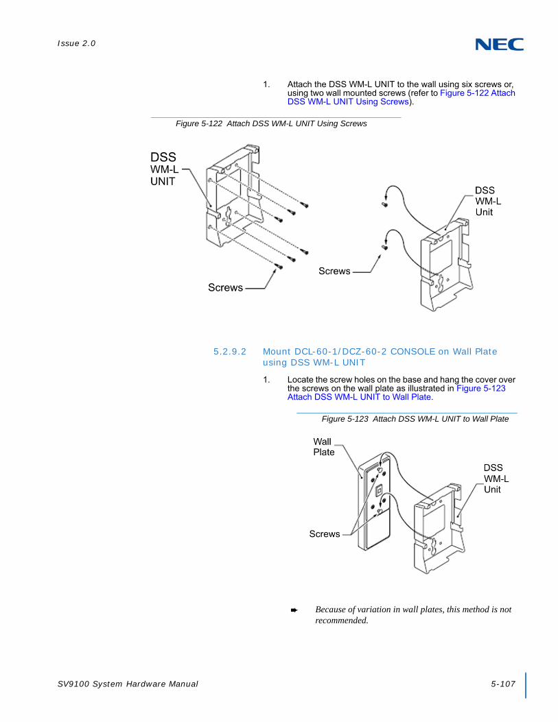
Issue 2.0
SV9100 System Hardware Manual 5-107
1. Attach the DSS WM-L UNIT to the wall using six screws or, using two wall mounted screws (refer to Figure 5-122 Attach DSS WM-L UNIT Using Screws).
5.2.9.2 Mount DCL-60-1/DCZ-60-2 CONSOLE on Wall Plate using DSS WM-L UNIT
1. Locate the screw holes on the base and hang the cover over the screws on the wall plate as illustrated in Figure 5-123 Attach DSS WM-L UNIT to Wall Plate.
Because of variation in wall plates, this method is not recommended.
Figure 5-122 Attach DSS WM-L UNIT Using Screws
Figure 5-123 Attach DSS WM-L UNIT to Wall Plate
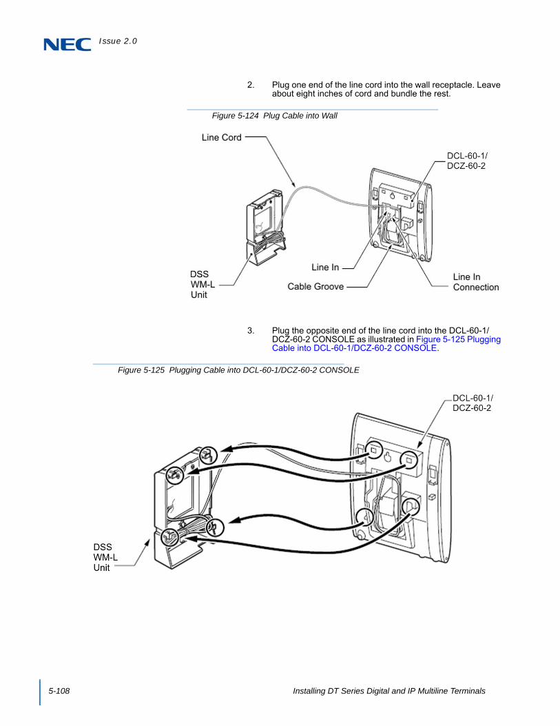
Issue 2.0
5-108 Installing DT Series Digital and IP Multiline Terminals
2. Plug one end of the line cord into the wall receptacle. Leave about eight inches of cord and bundle the rest.
3. Plug the opposite end of the line cord into the DCL-60-1/DCZ-60-2 CONSOLE as illustrated in Figure 5-125 Plugging Cable into DCL-60-1/DCZ-60-2 CONSOLE.
Figure 5-124 Plug Cable into Wall
Figure 5-125 Plugging Cable into DCL-60-1/DCZ-60-2 CONSOLE

SV9100 System Hardware Manual 6-1
Chapter 6
UNIVERGE® SV9100
Installing SV9100 Cordless Telephones
SECTION 1 GENERAL DESCRIPTION
This chapter provides information regarding cordless telephones that can be used with the UNIVERGE SV9100 system.
SECTION 2 BLUETOOTH CORDLESS HANDSET
2.1 Bluetooth Cordless Handset (BCH) Interface
This optional interface allows the multiline terminal user to use Bluetooth technology to provide a cordless handset. This handset provides:
Keyset-like Handset
Eight Line Buttons
Function Button
Dial Button
Display
All Multiline Terminal Functions with Main Unit
Cradle Charges Handset
Base Side RF Block (50 meters, Class 1)
Bluetooth Distance: 50 Meters
Up to 16 devices can be installed within a 100m (open area, ex: outdoors) or 50m (confined/blocked area, ex: indoors) radius and each device is located with 1 meter between each device simultaneously. This maximum can be affected by the installation environment.

Issue 2.0
6-2 Installing SV9100 Cordless Telephones
The BCH and a Bluetooth headset (BTH) cannot be used at the same time. When using a Bluetooth headset in place of the handset, the Plantronics Voyager 510 headset is recommended.
Table 6-1 Firmware Compatibility Matrix
BCH-L Unit Lot Number
xxxDxx or lower xxxExx or higher
Terminal Lot
Number DT-330
xxx I xx or lower(Version 8.10 and 1, E0 or lower)
Supported Supported
xxxJxx or higher(Version 2.20 or higher)
Not supported Supported
BCH Support may differ based on terminal firmware. To verify both DT-330 terminal and BCH-L Unit firmware, hold down keypad buttons 1, 2 and 3 while plugging the line cord into the terminal.

Issue 2.0
SV9100 System Hardware Manual 6-3
When charging the BCH, the following LEDs provide indications of the status:
The BCH retains call histories for up to 10 outgoing and 10 incoming calls. For outgoing calls, this includes completed and uncompleted calls. For incoming calls, this includes both answered and unanswered calls. The call history provides the date, time and telephone number for each call. When the limit is exceeded, the oldest call is deleted and replaced with the newest call.
2.2 Selecting a Location
Before choosing a location for your new telephone, consider these important guidelines:
If multiple cordless terminals are installed, keep their Bluetooth cradles at least 3.3 feet (1 meter) apart.
If the Bluetooth cradle is installed near a metal, concrete wall or any other structure that could affect radio transmission, a communication failure might occur.
Keep the Bluetooth cradle at least 9.8 feet (3 meters) away from any device listed below. Also be careful not to get within 9.8 feet (3 meters) of these devices when using the Bluetooth handset.
Microwave ovens
Wireless LAN access points (AP)
Medical apparatus
RFID (apparatus operating in the 2.4GHz band)
Manufacturing equipment, such as plasma strippers (LSI manufacturing)
Speedway electronic toll gates
Bluetooth devices
Table 6-2 BCH Charging LEDs
On-Hook Charging: Red = Charging Green = Charging Complete
Off-Hook (Idle): No LED = Idle Flashing Red = Incoming Call
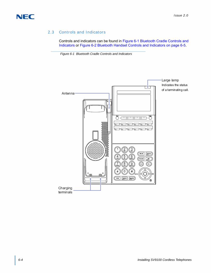
Issue 2.0
6-4 Installing SV9100 Cordless Telephones
2.3 Controls and Indicators
Controls and indicators can be found in Figure 6-1 Bluetooth Cradle Controls and Indicators or Figure 6-2 Bluetooth Handset Controls and Indicators on page 6-5.
Figure 6-1 Bluetooth Cradle Controls and Indicators

Issue 2.0
SV9100 System Hardware Manual 6-5
Figure 6-2 Bluetooth Handset Controls and Indicators

Issue 2.0
6-6 Installing SV9100 Cordless Telephones
2.4 Installing the Bluetooth Cordless Handset
The BCH-L (BK) UNIT is an optional device that transforms the standard multifunction telephone into a cordless terminal. This section explains how to transform the standard hand-set into a BCH-L (BK) UNIT. The BCH-L (BK) UNIT cannot be connected to the DTL-2E-1, DTL-6DE-1 or DTL-12-E-1 telephones.
2.4.1 Installing the Bluetooth Handset Cradle
1. Turn multiline terminal upside down.
2. Unplug the line cord and handset cord from the multiline terminal.
Only one BCH-L (BK) UNIT can be attached to the DTL multiline terminal.
3. Lower the tilt leg to the first position (refer to Figure 6-3 Separate Tilt Leg from Leg Support).
4. Push the two stopper tabs through the slots to separate the tilt leg from the leg support.
5. Lay the tilt leg and the leg support flat.
6. Press the two tabs locking the legs to the multiline terminal and pull the legs toward you, lifting to remove (refer to Figure 6-4 Remove Legs From Multiline Terminal on page 6-7).
WARNING
Before installing or removing the BCH-L (BK) UNIT, remove the line cord and the AC adapter from the outlet.
Figure 6-3 Separate Tilt Leg from Leg Support
Stoppers
Tilt Leg

Issue 2.0
SV9100 System Hardware Manual 6-7
7. Remove the side panel.
8. Disconnect serial connection cord from terminal body. Leave cord connected to the cradle unit.
9. Push the latch to the right to unlock the cradle unit. Then push the cradle unit forward to separate it from the terminal body (see Figure 6-5 Detach Cradle from Multiline Terminal).
Figure 6-4 Remove Legs From Multiline Terminal
Figure 6-5 Detach Cradle from Multiline Terminal

Issue 2.0
6-8 Installing SV9100 Cordless Telephones
10. Insert the cradle connecting cable of the Bluetooth Cradle (BTC) into the unit connector.
11. Fit the projections on the side of the Bluetooth Cradle into the guide holes on the side of the terminal and pull toward you (Figure 6-6 Attach Bluetooth Cradle to the Multiline Terminal) until the unit snaps into place.
12. Attach the side panel to the Bluetooth Cradle.
13. Press the connecting cable into the grooved cutout.
Figure 6-6 Attach Bluetooth Cradle to the Multiline Terminal
Figure 6-7 Grooved Cutout for Connecting Cable
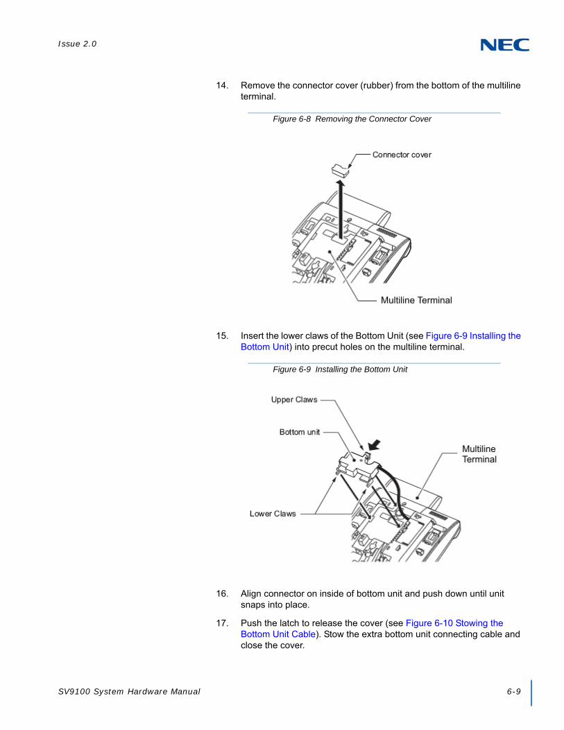
Issue 2.0
SV9100 System Hardware Manual 6-9
14. Remove the connector cover (rubber) from the bottom of the multiline terminal.
15. Insert the lower claws of the Bottom Unit (see Figure 6-9 Installing the Bottom Unit) into precut holes on the multiline terminal.
16. Align connector on inside of bottom unit and push down until unit snaps into place.
17. Push the latch to release the cover (see Figure 6-10 Stowing the Bottom Unit Cable). Stow the extra bottom unit connecting cable and close the cover.
Figure 6-8 Removing the Connector Cover
Figure 6-9 Installing the Bottom Unit

Issue 2.0
6-10 Installing SV9100 Cordless Telephones
18. Cut or trim the supplied coupled device for the tilt legs handset option.
19. Insert the stopper coupled device into the right and left tilt legs (see Figure 6-11 Insert Stopper for Handset Use).
20. Set the coupled device for tilt legs into position.
21. Reinstall the legs, pushing upwards until both locks snap into place.
22. Set tilt legs to desired position.
23. Place the multiline terminal with the numbered keypad up.
24. Connect the Line cord and the AC adapter.
Figure 6-10 Stowing the Bottom Unit Cable
Figure 6-11 Insert Stopper for Handset Use
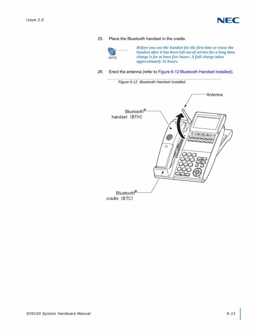
Issue 2.0
SV9100 System Hardware Manual 6-11
25. Place the Bluetooth handset in the cradle.
26. Erect the antenna (refer to Figure 6-12 Bluetooth Handset Installed).
NOTE
Before you use the handset for the first time or reuse the handset after it has been left out of service for a long time, charge it for at least five hours. A full charge takes approximately 16 hours.
Figure 6-12 Bluetooth Handset Installed

Issue 2.0
6-12 Installing SV9100 Cordless Telephones
2.4.2 Wall Mounting the Bluetooth Cradle
Clearances required for installing the Bluetooth cradle are shown below. Avoid mounting the cradle on a plaster-board wall, but before mounting the cradle on a wall, check that the wall can support the weight of the telephone and withstand the load from pulling the telephone during operation.
1. Attach two wood screws to the wall.
Keep a clearance of about 0.08” (2mm) between each wood screw and the wall (refer to Figure 6-14 Installing Wood Screws on page 6-13).
WARNING
To prevent possible damage to the BCH-L (BK) UNIT due to falling, NEC recommends installing the unit in a firm position so it cannot fall because of its own weight.
Figure 6-13 Wall Mount Spacing Guide BCH-L (BK) UNIT
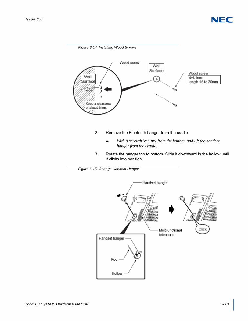
Issue 2.0
SV9100 System Hardware Manual 6-13
2. Remove the Bluetooth hanger from the cradle.
With a screwdriver, pry from the bottom, and lift the handset hanger from the cradle.
3. Rotate the hanger top to bottom. Slide it downward in the hollow until it clicks into position.
Figure 6-14 Installing Wood Screws
Figure 6-15 Change Handset Hanger

Issue 2.0
6-14 Installing SV9100 Cordless Telephones
4. Turn multiline terminal upside down.
5. Lower the tilt leg to the first position (refer to Figure 6-3 Separate Tilt Leg from Leg Support).
6. Hook the wall mount holes (C and D) on the back of the terminal on wood screws (c and d) installed.
Figure 6-16 Separate Tilt Leg from Leg Support
Stoppers
Tilt Leg
Figure 6-17 Wall Mounting the Terminal

Issue 2.0
SV9100 System Hardware Manual 6-15
2.4.3 Remove and Replace Handset Battery
The battery loaded in the Bluetooth handset has a useful life of about two years, depending on how the handset is used. If the battery voltage diminishes quickly after the battery has been charged for a long time, replace with a new Li-ion battery.
1. Remove cover from back of handset.
2. Remove existing battery and dispose of properly.
3. Install new Li-ion battery.
4. Reinstall battery cover.
Figure 6-18 Removing Battery Cover from Handset
Figure 6-19 Removing Battery from Handset
NOTE Full charge takes approximately 16 hours.

Issue 2.0
6-16 Installing SV9100 Cordless Telephones
SECTION 3 BLUETOOTH HUB ADAPTER
3.1 Bluetooth Hub Adapter (BHA) Features
The BHA-L UNIT adapter connects a Bluetooth device to a multiline terminal. The BHA-L UNIT cannot be connected to the DTL-2E-1, DTL-6DE-1 or DTL-12E-1 telephone.
3.1.1 Installing the BHA-L UNIT
1. Turn multiline terminal upside down.
2. Unplug the line cord and handset cord from the multiline terminal.
Only one BHA-L UNIT can be attached to the DTL multiline terminal.
3. Lower the tilt leg to the first position (refer to Figure 6-20 Separate Tilt Leg from Leg Support).
4. Remove the connector cover (rubber) from the bottom of the multiline terminal (see Figure 6-21 Removing the Connector Cover on page 6-17).
IMPORTANT
Before installing or removing the BHA-L UNIT, remove the line cord and the AC adapter from the outlet.
Figure 6-20 Separate Tilt Leg from Leg Support
Stoppers
Tilt Leg

Issue 2.0
SV9100 System Hardware Manual 6-17
5. Insert the lower claws of the Bottom Unit (see Figure 6-22 Installing the BHA-L UNIT) into precut holes on the multiline terminal.
6. Align connector on inside of BHA-L UNIT and push down until unit snaps into place.
7. Set tilt legs to desired position.
8. Place the numbered keypad up.
9. Connect the Line cord and the AC adapter.
Figure 6-21 Removing the Connector Cover
Figure 6-22 Installing the BHA-L UNIT

Issue 2.0
6-18 Installing SV9100 Cordless Telephones
3.1.2 Pairing a Bluetooth Device and Multiline Terminal (Bluetooth Installed)
Access the Bluetooth screen from a multiline terminal menu and register the Bluetooth headset with the BHA-L UNIT.
3.1.2.1 Accessing the Bluetooth Device Setup Screen
From the multiline terminal, access the setup screen using one of the following:
If the BHA-L UNIT is connected to an SV9100:Press menu keys > [5. Optional Devices] > [1. Bluetooth].
If the BHA-L UNIT is connected to a PBX (other than SV9100):Press menu keys > [3. Setup] > [5. Optional Devices] > [1. Bluetooth].
3.1.2.2 Entering a PIN Code
In pairing a Bluetooth device having a PIN Code other than 0000, enter a string of four to 16 digits to suit that device.
3.1.2.3 Pairing
Up to eight Bluetooth devices can be located around the BHA-L UNIT, select which can be paired with the device (refer to Figure 6-24 Pairing a Device).
Figure 6-23 Entering a PIN Code
Figure 6-24 Pairing a Device

Issue 2.0
SV9100 System Hardware Manual 6-19
3.1.2.4 Connecting the Paired Device
Enable the Bluetooth device. Select [2 Enable] in the Connect screen.
3.1.2.5 Unpairing
To unpair a paired the Bluetooth device, select the device in the [Delete] screen.
3.1.2.6 Visibility Setting
Set to Disable (default: [1. Disable]).
CAUTION
After pairing a Bluetooth device, be sure to configure its connection to enable it. If settings are not completed, the Bluetooth device that does the pairing cannot be used.
Figure 6-25 Connecting the Paired Device
Figure 6-26 Unpairing a Device
Figure 6-27 Setting Visibility Option
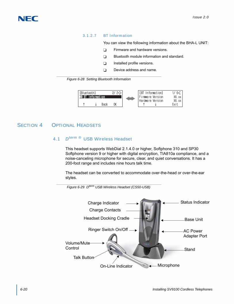
Issue 2.0
6-20 Installing SV9100 Cordless Telephones
3.1.2.7 BT Information
You can view the following information about the BHA-L UNIT:
Firmware and hardware versions.
Bluetooth module information and standard.
Installed profile versions.
Device address and name.
SECTION 4 OPTIONAL HEADSETS
4.1 Dterm ® USB Wireless Headset
This headset supports WebDial 2.1.4.0 or higher, Softphone 310 and SP30 Softphone version 9 or higher with digital encryption, TIA810a compliance, and a noise-canceling microphone for secure, clear, and quiet conversations. It has a 200-foot range and includes nine hours talk time.
The headset can be converted to accommodate over-the-head or over-the-ear styles.
Figure 6-28 Setting Bluetooth Information
Figure 6-29 Dterm USB Wireless Headset (CS50-USB)
Volume/Mute Control
Talk Button
On-Line Indicator Microphone
Ringer Switch On/Off
Headset Docking Cradle
Charge Indicator Status Indicator
AC Power Adapter Port
Charge Contacts
Stand
Base Unit
Issue 2.0
SV9100 System Hardware Manual 6-21
4.1.1 Installing the Base Unit
Attach the Base Unit to the stand pegs, and connect the USB connector to a free USB port on your computer. A USB hub can be used, if you are certain that it can supply the required 250mA to charge the headset. An optional AC power adapter can be installed in the AC Power Adapter Port.
4.1.2 Installing the PerSonoCall Software
To install the software, insert the CD supplied with the unit. If the CD does not autoplay, use Windows Explorer to find the file called install.bat, double click on it, and follow the instructions on the screen.
4.1.3 Charging the Headset Battery
To charge the headset battery, place it in the docking cradle. During charging, the charge indicator is On. When charging is complete the indicator goes Off. The headset must be charged for a minimum of one hour before use – three hours to fully charge.
4.1.4 Initial Setup
The Unit includes a base ringer to provide notification of an incoming call when not wearing your headset. This feature is enabled when the Ringer switch is down and is disabled when the switch is up.
When the headset is installed, it sets itself as the default device in your computer. You can set your preferences manually in Windows through the Sounds and Audio Devices option in the control panel. A softphone may require choosing the audio device and carries out a short test to match this device to the softphone. It may also enable you to choose which device indicates an incoming call. Refer to the softphone documentation for more information.
4.1.5 Using the Headset
Refer to the User Guide for operating procedures.

Issue 2.0
6-22 Installing SV9100 Cordless Telephones
4.2 Headsets Used with Dterm ® Telephones
A multiline terminal user can use a customer-provided headset in place of the handset. Like using Handsfree, using the headset frees up the user’s hands for other work. However, Headset Operation provides privacy not available from handsfree.
The headset plugs into a separate jack on the bottom of the phone. This allows the use of the handset or headset – whichever is more convenient at the time.
Connect the headset in the headset jack located on the bottom of the multiline terminal. (This jack is located next to the handset jack, so make sure to connect to the proper jack.)
4.2.1 NEC Dterm ® Headset (MX250)
The M Series Pin Jack Style headset MX250 allows maximum versatility for wireless or cordless phones. The MX250 is easy to put on and can be worn in either ear. This headset includes an EarBudeez ™ stabilizer for best possible fit to prevent the headset from becoming dislodged during important conversations. Over-the-ear styling provides a comfortable fit.
Figure 6-30 Cordless Headset (MX250)
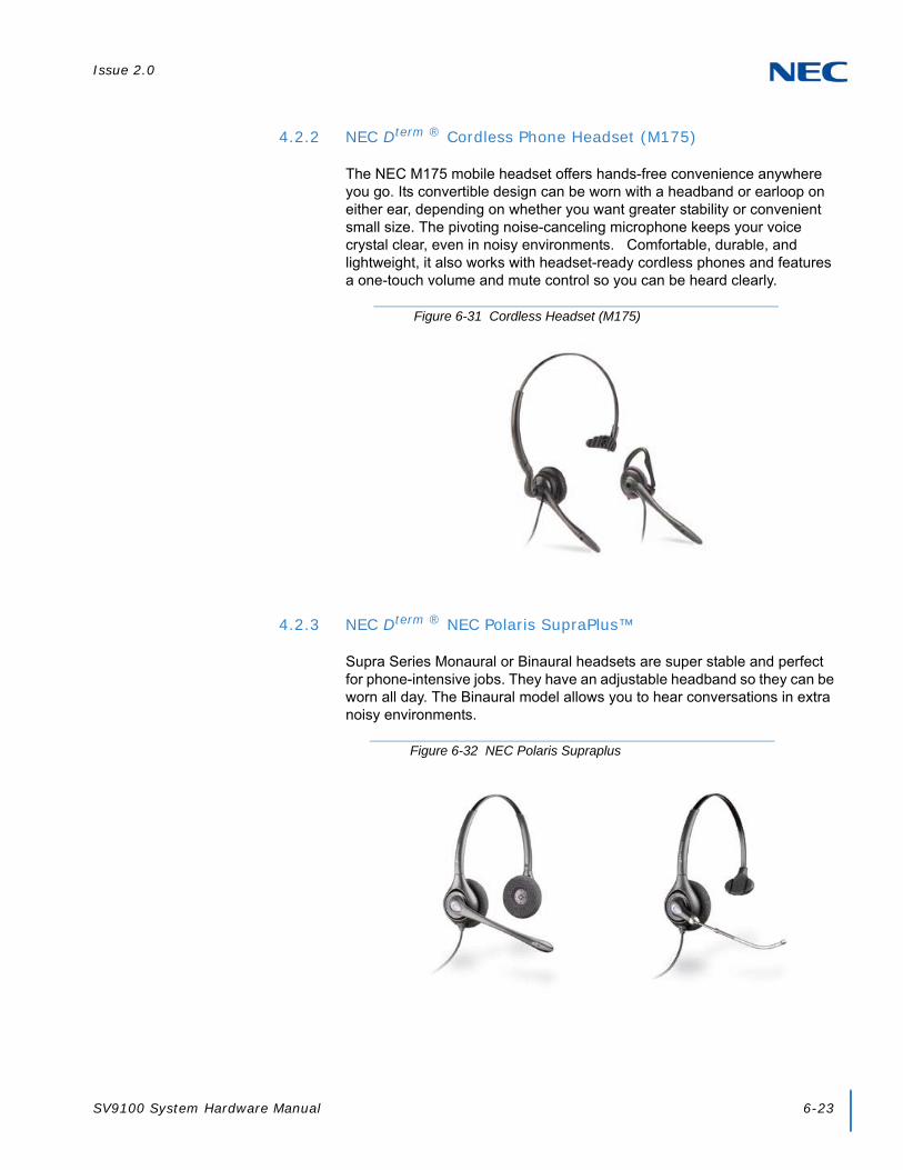
Issue 2.0
SV9100 System Hardware Manual 6-23
4.2.2 NEC Dterm ® Cordless Phone Headset (M175)
The NEC M175 mobile headset offers hands-free convenience anywhere you go. Its convertible design can be worn with a headband or earloop on either ear, depending on whether you want greater stability or convenient small size. The pivoting noise-canceling microphone keeps your voice crystal clear, even in noisy environments. Comfortable, durable, and lightweight, it also works with headset-ready cordless phones and features a one-touch volume and mute control so you can be heard clearly.
4.2.3 NEC Dterm ® NEC Polaris SupraPlus™
Supra Series Monaural or Binaural headsets are super stable and perfect for phone-intensive jobs. They have an adjustable headband so they can be worn all day. The Binaural model allows you to hear conversations in extra noisy environments.
Figure 6-31 Cordless Headset (M175)
Figure 6-32 NEC Polaris Supraplus
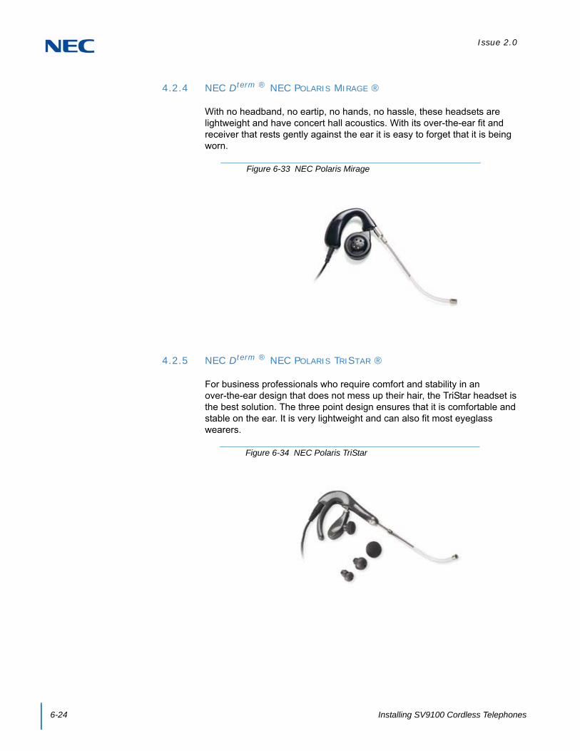
Issue 2.0
6-24 Installing SV9100 Cordless Telephones
4.2.4 NEC Dterm ® NEC POLARIS MIRAGE ®
With no headband, no eartip, no hands, no hassle, these headsets are lightweight and have concert hall acoustics. With its over-the-ear fit and receiver that rests gently against the ear it is easy to forget that it is being worn.
4.2.5 NEC Dterm ® NEC POLARIS TRISTAR ®
For business professionals who require comfort and stability in an over-the-ear design that does not mess up their hair, the TriStar headset is the best solution. The three point design ensures that it is comfortable and stable on the ear. It is very lightweight and can also fit most eyeglass wearers.
Figure 6-33 NEC Polaris Mirage
Figure 6-34 NEC Polaris TriStar
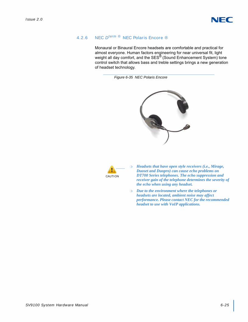
Issue 2.0
SV9100 System Hardware Manual 6-25
4.2.6 NEC Dterm ® NEC Polaris Encore ®
Monaural or Binaural Encore headsets are comfortable and practical for almost everyone. Human factors engineering for near universal fit, light weight all day comfort, and the SES® (Sound Enhancement System) tone control switch that allows bass and treble settings brings a new generation of headset technology.
Figure 6-35 NEC Polaris Encore
CAUTION
Headsets that have open style receivers (i.e., Mirage, Duoset and Duopro) can cause echo problems on DT700 Series telephones. The echo suppression and receiver gain of the telephone determines the severity of the echo when using any headset.
Due to the environment where the telephones or headsets are located, ambient noise may affect performance. Please contact NEC for the recommended headset to use with VoIP applications.

Issue 2.0
6-26 Installing SV9100 Cordless Telephones

SV9100 System Hardware Manual 7-1
Chapter 7
UNIVERGE® SV9100
Installing SV9100 Optional Equipment
SECTION 1 GENERAL INFORMATION
This chapter provides information for installing optional equipment, such as PGDADs, background music, door boxes, DSS consoles, external paging as well as other handsets, recording devices and adapters on the SV9100 digital and IP telephones.
SECTION 2 PGDAD
2.1 Using a PGDAD
The PGDAD provides two circuits which allow connection to external terminals such as:
Door Box (eight maximum per system)
External Speaker (eight maximum with PGDADs [with amplifier], one on the GCD-CP10 [no amplifier])
External Music Source (external MOH) (96 maximum per system)
External Recording System (96 maximum per system)
External Ringing
The system allows a maximum of 56 PGDADs to be installed (48 for ACI ports [external MOH or external recording system], four for Door Boxes, and four for Paging). The PGDADs also provides multi-purpose controls. These control relays can be used for controlling the external amplifier, external music source and door lock control with the use of a Door Box. The system allows up eight general purpose relays with the PGDADs (four relays on each PGDAD) and one on the GCD-CP10 for a maximum of nine.

Issue 2.0
7-2 Installing SV9100 Optional Equipment
The PGDAD connects to any available digital extension port. The terminal connections made in the PGDAD and the jumper settings determine what features are used for each circuit.
2.2 LED Indications
Table 7-1 PGDAD LED Indications lists the LED indications and provides a brief description of each.
2.3 Setting up PGDAD Connections
This sections provides instructions for setting up the PGDAD connections.
Figure 7-1 PGDAD
Channel 2Status LED
Channel 1Status LED
Table 7-1 PGDAD LED Indications
LED Indication Note
LED 1 Green LED when CH1 in use.
Flashing green LED indicates DIP Switch setting and programming for CH1 are conflicting.
LED 2 Green LED when CH2 in use.
Flashing green LED indicates DIP Switch setting and programming for CH2 are conflicting.
CAUTION
If the PGDAD is to be wall mounted, all the cable connections should be made first.
For the module to ID correctly after setting the jumpers, set the circuit type to 0 for the module port in Program 10-03-01 prior to connecting the line cord to the PGDAD.
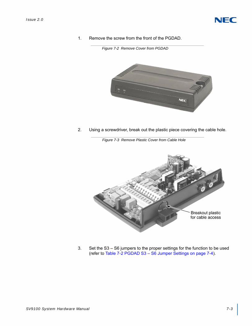
Issue 2.0
SV9100 System Hardware Manual 7-3
1. Remove the screw from the front of the PGDAD.
2. Using a screwdriver, break out the plastic piece covering the cable hole.
3. Set the S3 – S6 jumpers to the proper settings for the function to be used (refer to Table 7-2 PGDAD S3 – S6 Jumper Settings on page 7-4).
Figure 7-2 Remove Cover from PGDAD
Figure 7-3 Remove Plastic Cover from Cable Hole

Issue 2.0
7-4 Installing SV9100 Optional Equipment
Table 7-2 PGDAD S3 – S6 Jumper Settings
Channel 1
S3 S4 Function LED Indication
Open Open Door Box On when in use.
Open Short External Paging Speaker On when in use.
Short Open External Ringer On when in use.
Short Short External Music on Hold / Recording System
On steady.
Channel 2
S5 S6 Function LED Indication
Open Open Door Box On when in use.
Open Short External Paging Speaker On when in use.
Short Open External Ringer On when in use.
Short Short External Music on Hold / Recording System
On steady.
Figure 7-4 PGDAD Jumper Settings

Issue 2.0
SV9100 System Hardware Manual 7-5
4. Strip one end of the cable to be connected to the control relay or door box so that approximately 1/4” (8mm) of bare wire is exposed.
5. Insert the cable into the proper CN4 or CN5 location while holding down the lock button (holding down this lock button is easiest with a flat-head screwdriver). Once the cable is in place, release the lock button.
NOTE
Refer to the specific function being connected for more detail on PGDAD connections.

Issue 2.0
7-6 Installing SV9100 Optional Equipment
Figure 7-5 PGDAD Connection Diagram

Issue 2.0
SV9100 System Hardware Manual 7-7
6. Repeat Steps 4 and 5 for any additional connection required.
7. Replace the cover and tighten the screw to hold the cover in place.
8. If required for the function being used, insert the RCA connectors into the CN2 (Channel 1) and CN3 (Channel 2) connectors on the back of the PGDAD.
Figure 7-6 Connecting Cable to the PGDAD
Flat-head screwdriver
Press downCable
CN4, CN5

Issue 2.0
7-8 Installing SV9100 Optional Equipment
9. Install a modular jack for each PGDAD. For each module, run one-pair 24 AWG station cable from the cross-connect block to a modular jack. Ground the unused pair.
10. Terminate the extension leads to GRN/RED of the modular jack. Terminate the unused leads to the jack.
11. Install bridging clips as required.
12. Plug a modular line cord from the mod jack to the CN1 connector on the PGDAD.
Figure 7-7 PGDAD Connections
CAUTION
For the module to ID correctly, set the circuit type to 0 for the port in Program 10-03-01 prior to connecting the line cord.
CAUTION
In some cases, while testing the operation of an extension port that is connected to a Cordless II, Cordless Lite II, or PGDAD, a technician may connect a line cord directly from an extension port on the CD-8DLCA/CD-16DLCA blade. Though this is not the recommended connection, it can be used to test these devices.
Should a direct connection of this type be made to the base station of the Cordless II or Cordless Lite II, or to a PGDAD, the line cord must be 2-wire (1-pair). If a 2-pair wire is used, the system provides power to the unused pair. This can prevent the cordless telephone from acquiring a link with the base station or it can damage the PGDAD or the SV9100 station card.
The recommended connection is to punch down 2 wires to the cross-connect block, then connect the extension block to the RJ-61 connector on the blade.

Issue 2.0
SV9100 System Hardware Manual 7-9
13. Optional:To wall mount the PGDAD, insert two wood screws 100mm apart (3 15/16”). Leave 3mm (1/8”) of the screw exposed. The screws can be installed either vertical or horizontal, depending on which position fits best for your location.
14. The back of the PGDAD has two key-hole type openings. Place the PGDAD over the two screws and slide it down or over (depending on the positioning) to lock it in place.
Figure 7-8 Installing the Screws
Figure 7-9 Wall Mounting the PGDAD

Issue 2.0
7-10 Installing SV9100 Optional Equipment
SECTION 3 BACKGROUND MUSIC
3.1 Installing Background Music
Background Music (BGM) sends music from a customer-provided music source to speakers in Multiline terminals. If an extension user activates it, BGM plays when the user’s extension is idle.
1. Connecting to the GCD-CP10:Connect an RCA line from the AUX1 or AUX2 connector on the GCD-CP10 to the appropriate location on the extension cross-connect block.
2. Connect the two-conductor station cable from the cross-connect block to the external music source.
3. Install bridging clips as required.
SECTION 4 DOOR BOX
4.1 Installing a Door Box
The Door Box is a self-contained, water-resistant, Intercom unit typically used to monitor an entrance door. A visitor at the door can press the Door Box call button (like a door bell). The Door Box then sends chime tones to all extensions programmed to receive chimes. The system can have up to eight Door Boxes.
Figure 7-10 CPRU Connections
IMPORTANT
A PGDAD is required for this option.

Issue 2.0
SV9100 System Hardware Manual 7-11
Each PGDAD audio output can optionally support two analog Door Boxes. In addition, you can connect each circuit control relay to an electric door strike. This allows an extension user to remotely activate the door strike while talking to a visitor at the Door Box. The control relays are normally open. The GCD-CP10 also provides one general purpose relay. The GCD-CP10 relay 0 is assigned to the door box extension port in Program10-05-01. When the relay on the PGDAD is used, there is no need to assign the relay to the Door Box. Connect the relay as detailed in the steps below for the Door Box used. The relays on the PGDADs are numbered 5-8.
1. Make sure the jumper in the PGDAD for the associated Door Box is set correctly. (Refer to Figure 7-4 PGDAD Jumper Settings on page 7-4).
2. If a line cord was not previously connected to the PGDAD, complete Steps 3-6. Otherwise, skip to Step 7.
3. Install a modular jack for each PGDAD. For each module, run one-pair 24 AWG station cable from the cross-connect block to a modular jack. Ground the unused pair.
4. Terminate the extension leads to GRN/RED of the modular jack. Terminate the unused leads to the jack.
5. Install bridging clips as required.
6. Plug a modular line cord from the mod jack to the CN1 connector on the PGDAD.
7. If wall mounting the Door Box, remove the screw on the front of the Door Box.
8. Remove the back half of the Door Box and attach this mounting bracket to the wall with the two screws provided.
9. Connect the two-conductor station cable from the CN4 connectors in the PGDAD to the Door Box terminals. These wires must be routed through the opening in the bottom of the Door Box mounting bracket..
10. Replace the front half of the Door Box and reattach the screw to secure it in place.
NOTE
The relay closes when the Door Box/external page zone is called. The maximum applied voltage is 24vDC at .5A for each contact.
CAUTION
A PGDAD circuit used for an analog Door Box cannot be used for External Paging.
NOTE Be sure to maintain the proper polarity.

Issue 2.0
7-12 Installing SV9100 Optional Equipment
11. To connect a Door Box to an external relay for an unlock device, for example, connect one-pair 24 AWG station cable from the Relay 5 (for Door Box 1) or Relay 6 (for Door Box 2) connectors (CN5) in the PGDAD. Connect the opposite end to the unlock device.
Refer to section 6.2 Door Box /External Page Relay Contacts on page 7-16 for additional information when using the GCD-CP10 relay.
Figure 7-11 Setting the PGDAD for a Door Box

Issue 2.0
SV9100 System Hardware Manual 7-13
Figure 7-12 Installing a Door Box

Issue 2.0
7-14 Installing SV9100 Optional Equipment
SECTION 5 EXTERNAL PAGING
5.1 External Page
Two external page zone/door box circuits are provided by each PGDAD installed. Each Door Box/external page circuit provides a dry relay contact. The GCD-CP10 also provides a connection for external paging and a relay. The external page on the GCD-CP10 is speaker number 9 – the relay is number 0. The external page speakers provided by the PGDADs are 1~8 – the relays on the PGDADs are numbered 1~8.
The PGDAD can be used for talkback with External Page, as can a CO trunk port with the proper external page equipment (ex: Valcom) – set Program 31-06-03 to 0 for talkback. However, the external page circuit on the GCD-CP10 cannot be used for talkback.
5.2 Installing an External Page System
1. Connecting to the GCD-CP10:Connect an RCA line from the AUX1 or AUX2 connector on the GCD-CP10 to the appropriate location on the extension cross-connect block.
2. Connect the two-conductor station cable from the cross-connect block to the external relay/external page.
3. Install bridging clips as required.
-OR-
1. Connecting to the PGDAD:Make sure the jumper in the PGDAD for the channel is set correctly. (Refer to Figure 7-4 PGDAD Jumper Settings on page 7-4).
2. If a line cord was not previously connected to the PGDAD, complete Steps 3-6. Otherwise, skip to Step 7.
3. Install a modular jack for each PGDAD. For each module, run one-pair 24 AWG station cable from the cross-connect block to a modular jack. Ground the unused pair.
4. Terminate the extension leads to GRN/RED of the modular jack. Terminate the unused leads to the jack.
5. Install bridging clips as required.
6. Plug a modular line cord from the mod jack to the CN1 connector on the PGDAD.
CAUTION
A PGDAD circuit used for External Paging cannot be used for an analog Door Box.

Issue 2.0
SV9100 System Hardware Manual 7-15
7. Connect the two-conductor station cable from the CN5 connectors in the PGDAD to the external relay/external page.
Figure 7-13 PGDAD Cable Connection
TIP
The PGDAD provides amplifiers for each page output port (for a maximum of +8 dBM, 600 ohms at 1KHz). No additional page amplification is provided by the PGDAD but, if required, an external page amplifier can be used for additional amplification.
The page output of the GCD-CP10 does not provide amplification (for a maximum output of -3 dBm, 600 ohms at 1KHz). If the paging volume is not satisfactory using the AUX1 or AUX2 connector on the GCD-CP10, the PGDAD should be used instead.

Issue 2.0
7-16 Installing SV9100 Optional Equipment
SECTION 6 EXTERNAL PAGING AND DOOR BOX/PAGE RELAYS
6.1 External Page Relays
Two external dry contact relays are available when a PGDAD is installed which can be used to activate ancillary devices (i.e. door unlock devices). The GCD-CP10 also provides one page relay. When the relay on the PGDAD is used, there is no need to assign the relay to the Door Box – connect the relay as detailed in the steps below for the Door Box used. The relays on the PGDADs are numbered 5~8. Each Door Box/external page circuit provides a dry relay contact.
The service codes indicated are the default codes. Refer to Program 11-12-20 and 11-12-50 to redefine these codes as needed.
6.2 Door Box /External Page Relay Contacts
6.2.1 Connecting a Contact Relay Device to a Door Box/External Page Relay
Connect a dry contact relay device to a Door Box/External Page Relay.
To connect to the GCD-CP10:
1. Connect an RCA line from the AUX1 or AUX2 connector on the GCD-CP10 to the appropriate location on the extension cross-connect block.
2. Connect the two-conductor station cable from the cross-connect block to the external relay.
3. Install bridging clips as required.
-OR-
To connect to the PGDAD:
1. Make sure the jumper in the PGDAD for the channel is set correctly. (Refer to Figure 7-4 PGDAD Jumper Settings on page 7-4).
2. If a line cord was not previously connected to the PGDAD, complete Steps 3~6. Otherwise, skip to Step 7.
CAUTION
If Relays 5 and 6 of a PGDAD are set as General Purpose Relays, they cannot be used for Door Box/Page Relays.
Program 10-21-05 sets the relay switch on the GCD-CP10.
If General Purpose Relay is set to 1 (Relay 1), the page relay cannot function on the GCD-CP10. General Purpose Relays override Paging Relays and the Paging Relay is associated with Relay 1 on J10 (CONTROL RELAY).

Issue 2.0
SV9100 System Hardware Manual 7-17
3. Install a modular jack for each PGDAD. For each module, run one-pair 24 AWG station cable from the cross-connect block to a modular jack. Ground the unused pair.
4. Terminate the extension leads to GRN/RED of the modular jack. Terminate the unused leads to the jack.
5. Install bridging clips as required.
6. Plug a modular line cord from the mod jack to the CN1 connector on the PGDAD.
7. Connect the two-conductor station cable from the CN5 connectors in the PGDAD to the external relay.
SECTION 7 EXTERNAL RECORDING SYSTEM/EXTERNAL RINGER
7.1 External Recording System or External Ringer
The PGDAD allows the connection of an external recording system or external ringer. With a customer-provided tape recorder, when an extension user dials the ACI analog port extension number, they can automatically start the recorder and activate the record function. When the user hangs up, the recording stops and the tape recorder turns off. For tape recording, connect the tape recorder AUX input jack to the PGDAD jack. Connect the recorder control leads (if available) to the CTL (control relay) jack. By using Department Calling, you can arrange multiple tape recorders into a pool. When an extension user dials the Department Group pilot number, they reach the first available tape recorder in the pool.
The relays in the PGDAD can optionally control customer-provided external ringers (loud bells) and buzzers. When an extension user dials the ACI analog port extension number, the associated PGDAD relay closes and activates the
NOTE
The relay closes when the Door Box/external page zone is called. The maximum applied voltage is 24vDC at 0.5A for each contact.
Figure 7-14 GCD-CP10 Page Connections

Issue 2.0
7-18 Installing SV9100 Optional Equipment
ringer. You could use this ability to control an emergency buzzer for a noisy machine shop floor, for example. In addition, if programmed for ringing, an incoming trunk call can activate the ringer/buzzer.
7.2 Installing an External Recording System or External Ringer
To connect to the PGDAD:
1. Make sure the jumper in the PGDAD for the channel is set correctly. (Refer to Figure 7-4 PGDAD Jumper Settings on page 7-4).
2. If a line cord was not previously connected to the PGDAD, complete Steps 3~6. Otherwise, skip to Step 7.
3. Install a modular jack for each PGDAD. For each module, run one-pair 24 AWG station cable from the cross-connect block to a modular jack. Ground the unused pair.
4. Terminate the extension leads to GRN/RED of the modular jack. Terminate the unused leads to the jack.
5. Install bridging clips as required.
6. Plug a modular line cord from the mod jack to the CN1 connector on the PGDAD.
7. Connect an RCA jack to the audio output(s) on the back of thePGDAD.
8. The opposite end of this cable is connected to the external recording system or external ringer either directly or by connecting to the cross-connect block where the item is connected. Refer to Figure 7-15 PGDAD Cable Connection on page 7-19.

Issue 2.0
SV9100 System Hardware Manual 7-19
7.3 Programming
10-03-01 : ETU Setup – Terminal Type (Circuit 1)10-03-06 : ETU Setup – Terminal Type (Circuit 2)Confirm that the PGDAD has defined the circuit as either type 7 for External Ringer or 9 for ACIs. (If the PGDAD circuit was previously defined for another type of circuit, unplug the PGDAD and plug it back in to reset the circuit type.)
10-05-01 : General Purpose Relay SetupDefine which relay circuits (5~8) on the PGDAD are used for General Purpose Relays.
11-06-01 : ACI Extension NumberingAssign extension numbers to ACI software ports. Select a number outside of the normal extension number range. ACI Ports 1~96
Figure 7-15 PGDAD Cable Connection
Issue 2.0
7-20 Installing SV9100 Optional Equipment
11-08-01 : ACI Group Pilot NumberAssign pilot numbers to ACI groups. When a user dials the pilot number, they reach an available ACI software port in the group. ACI Groups 1~16
11-12-50 : Service Code Setup (For Service Access)Specify the service code to toggle the relay open and closed (Default: 780).
33-01-01 : ACI Port Type SetupSet each ACI software port for input (1) or input/output (2). Use input ports for Music on Hold sources. Use output ports for External Paging/ringer control.ACI Ports 1~96
33-02-01 : ACI Department Calling GroupAssign ACI software ports to ACI Department Groups. This lets ACI callers connect to ACI software ports by dialing the group pilot number (set in Program 11-08).ACI Ports 1~8, ACI Groups 1-16
ACI Recording
14-09-01 : ACI Conversation Recording Destination for Trunks – ACI Recording Destination Extension NumberUse this option to assign the ACI Call Recording destination per trunk. The destination can be an ACI port extension number (assigned in Program 11-06-01) or an ACI Department Group pilot number (assigned in Program 11-08-01). If destinations are assigned in Programs 14-09 and 15-12, the destination in Program 15-12 is followed.
14-09-02 : ACI Conversation Recording Destination for Trunks – ACI Automatic Recording for Incoming CallDetermine whether a trunk should be automatically recorded when an incoming call is received (0=Off, 1=On).
15-07 : Programmable Function KeysIf required, program an ACI Conversation Record Key (SC 751 + 78). This key allows an extension user to press the key to manually record a call to the ACI.
15-12-01 : Conversation Recording Destination for Extensions – ACI Recording Destination Extension NumberAssign the ACI Call Recording destination per extension. The destination can be an ACI port extension number (assigned in Program 11-06) or an ACI Department Group pilot number (assigned in Program 11-08). If destinations are assigned in Programs 14-09 and 15-12, the destination in Program 15-12 is followed.
15-12-02 : Conversation Recording Destination for Extensions – ACI Automatic Recording for Incoming CallDetermine whether an extension should be automatically recorded when an incoming call is received (0=Off, 1=On).

Issue 2.0
SV9100 System Hardware Manual 7-21
External Ringer
31-05-01 : Universal Night Answer/Ring Over PagingFor each trunk port which should ring the external ringer, enter 1.
SECTION 8 MUSIC SOURCES
8.1 Music on Hold
The system can provide Music on Hold from either an internally synthesized source on the GCD-CP10 or from an external source. The external MOH can be a tuner, tape deck, CD player, etc. The settings in Program 10-04-01 and 14-08-01 determine whether the source for MOH is internal or external.
In addition to a connector on the GCD-CP10, the PGDADs also provide connections for external MOH sources. When using external music sources for external MOH, programming determines the MOH source for each trunk.
The GCD-CP10 provides a dry relay that activates when a call is placed on Hold. When an external MOH source is connected to the MOH relay and a call is placed on Hold, the MOH relay is activated. This allows an external relay sensor/power supply to turn on the MOH source.
This arrangement allows the MOH source (e.g., a tape deck) to run only when a call is placed on Hold. The maximum applied voltage for the relay is 24vDC at 0.5A (the relays are normally open and close when a call is put on hold).
8.2 Installing External Music on Hold
To connect to the GCD-CP10
1. Connect an RCA line from the AUX1 or AUX2 connector on the GCD-CP10 to the appropriate location on the extension cross-connect block.
2. Connect the two-conductor station cable from the cross-connect block to the external music source.
3. Install bridging clips as required.
-OR-
Connecting to the PGDAD:
1. Make sure the jumper in the PGDAD for the channel is set correctly. (Refer to Figure 7-4 PGDAD Jumper Settings on page 7-4).

Issue 2.0
7-22 Installing SV9100 Optional Equipment
2. If a line cord was not previously connected to the PGDAD, complete Steps 3~6. Otherwise, skip to Step 7.
3. Install a modular jack for each PGDAD. For each module, run one-pair 24 AWG station cable from the cross-connect block to a modular jack. Ground the unused pair.
4. Terminate the extension leads to GRN/RED of the modular jack. Terminate the unused leads to the jack.
5. Install bridging clips as required.
6. Plug a modular line cord from the mod jack to the CN1 connector on the PGDAD.
7. Connect an RCA jack to the audio output(s) on the back of the PGDAD.
8. The opposite end of this cable is connected to the external music source either directly or by connecting to the cross-connect block where the music source is connected.
Figure 7-16 CPRU Connections

Issue 2.0
SV9100 System Hardware Manual 7-23
Figure 7-17 PGDAD Connections

Issue 2.0
7-24 Installing SV9100 Optional Equipment
SECTION 9 NIGHT MODE SELECTION
9.1 Night Mode Selector Switch
The Night Mode Switch relay closes when the system detects either an open or closure on the MISC block NIGHT SW terminals. Maximum 48v DC is output to the switch when open, and 7mA DC when shorted.
9.2 Connecting a Night Mode Selector Switch
1. Connect an RJ-61 modular line cord from the J10 (CONTROL RELAY) connector on the GCD-CP10 to the appropriate location on the extension cross-connect block.
2. Connect the two-conductor station cable from the cross-connect block to the night switch mechanism output leads.
3. Install bridging clips as required.
SECTION 10 TELEPHONE LABELING
10.1 DESI Printer Sheets
Telephones can be easily labeled by removing the plastic faceplate. These labels can be printed by hand, typewriter, or printing DESI labels. Labels for this are on 8 1/2 x 11” paper, which allows for easy printing by any printer – dot matrix, laser, etc.
DESI Printer Sheets are available for the following:
Economy 2E – DESI ITL/DTL-2E (25 PKG)
Economy 6DE – DESI ITL/DTL-6DE (25 PKG)
All Value Telephones – DESI ITL/DTL-12D/24D (25 PKG)
8LK – DESI ITL/DTL 8LK (25 PKG)
60 DSS – DESI DCL-60 (25 PKG)
Clear Side Panel – DESI ITL/DTL-SIDE (25 PKG)
LCD Value, Clear Side – DESI ITL/DTL-SIDE-LCDV (25 PKG)

Issue 2.0
SV9100 System Hardware Manual 7-25
10.1.1 Removing the Faceplate
1. Use the small notch at the lower right corner of the telephone, to lift the faceplate up.
Each corner has a plastic locking pin which releases as the faceplate is lifted up.
2. Replacing the Faceplate
1. Place the faceplate back on the telephone.
2. At each corner, press the locking pin back into place.
Figure 7-18 Removing the Faceplate

Issue 2.0
7-26 Installing SV9100 Optional Equipment
SECTION 11 TELEPHONE ADAPTERS
11.1 Using Adapters
The modular terminals can support installing one additional adapter underneath the terminal. These adapters provide the multiline terminal different abilities, depending on the adapter installed.
These optional adapters are not installed on non-modular telephones.
Only the ILPA, ADA and PSA Adapters can be used on the IP phones.
ADA – Conversation Recording
APR – Analog Port Adapter with Ringer
PSA – Multiline Terminal/IP Phone Power Failure
Telephones with any adapter installed require an optional wall mount unit (WM-L) to be wall mounted. The bracket does not accommodate the adapter(s).
11.2 In-line Power Adapter (ILPA-R)
The In-Line Power Adapter (ILPA-R), which is IEEE 802.3af compliant, detects power from a PoE-compatible Ethernet switch and passes it to the IP terminal. The ILPA does the negotiation and detection with the switch and then relays the power to the IP terminal device. This provides an additional way to power the NEC IP terminals. With this adapter, the IP terminals on the UNIVERGE SV9100 system can be powered using:
Local power connecting the IP terminal to a local AC wall outlet using the AC-R Adapter
NEC power supply PoE-managed switch (BlueFire 200/24) (in-line and spare pair detection)
Figure 7-19 Installing Adapters
CAUTION
Before installing or removing the adapter, the multiline terminal should be unplugged from the system. External power is not required for the adapter.

Issue 2.0
SV9100 System Hardware Manual 7-27
Router Blade (spare pair detection)
Cisco Data Switch – CDP supported (in-line and spare pair detection)
In-Line Power Adapter
11.2.1 Conditions
Only IP telephones supported by center feed can be used.
This adapter cannot be used with the H.323 telephones.
When center feed is used, unplug the adapter from the Ethernet switch before changing the SW1 setting on the back of the adapter.
The ILPA-R adapter is intended for use with IP phones and IP Adapters. Installing any other device into the telephone port of the ILPA-R may result in damage to the device.
When powering an IP phone using an ILPA-R adapter, the phone should not be connected to a port on the Router Blade.
Figure 7-20 In-Line Power Adapter

Issue 2.0
7-28 Installing SV9100 Optional Equipment
When using center feed, set the SW1 switch located on the back of the adapter as follows:
11.2.2 Installation
1. Set the SW1 switch on the ILPA-R adapter to the correct setting for the Ethernet switch to which it is to be connected.
2. Set the switch setting on the NEC IPhone or IP adapter to the correct position.
Figure 7-21 In-Line Power Adapter Switch Settings
Center Feed Hub System SW1 Setting
IEEE802.3af STD System 1
Cisco Discovery Protocol System 1
NEC BlueFire 200/24 Switch 2
Center Feed Hub System SW1 Setting
IEEE802.3af STD System 1
Cisco Discovery Protocol System 1
NEC BlueFire 200/24 Switch 2
IPhone (SW2) or IP Adapter (SW1) SW Setting
NEC Power Patch Panel(12-port NEC SN1604 PWRMS, 24-port NEC BlueFire 200/24)8SHUBU Blade
1
Cisco Catalyst Power Patch PanelCisco Catalyst PRW Series
2

Issue 2.0
SV9100 System Hardware Manual 7-29
3. Connect the NEC VoIP telephone to the TEL connector on the ILPA-R adapter with the LAN cable provided with the adapter.
If a customer-provided cable is used, the total length from the switch to the telephone should be less than 328 feet.
The adapter can be positioned either closer to the multiline terminal or switch – it does not matter.
4. Connect a crossover LAN cable to the LAN connector on the ILPA-R adapter. Plug the opposite end into the switch which is to provide power to the telephone. Refer to Figure 7-22 NEC Terminal Connection to an IEEE 802.3af PoE Switch.
If a straight-through cable is used, NIC Auto Detection must be enabled in Programs 10-12-05 (GCD-CP10), 84-05-02 (VOIPU) or 85-01-03 (SHUBU).
Figure 7-22 NEC Terminal Connection to an IEEE 802.3af PoE Switch

Issue 2.0
7-30 Installing SV9100 Optional Equipment
11.3 ADA-L UNIT
Using the ADA-L UNIT (Ancillary Device Adapter) provides a recording jack connection from a telephone to an external tape recorder, speaker or PC. Both sides of the conversation are recorded. The adapter output is a 1/8” audio (stereo) jack which you can connect directly to an AUX level input on a recorder or page amplifier.
Recording a conversation (Handset/Headset/Hands-free), or sending recorded calls to a telephone are possible by connecting a cassette recorder to the ADA-L UNIT (voice recording and the playback of a recorded sound from a cassette recorder cannot occur at the same time).
Before installing or removing the adapters, the multiline terminal should be unplugged from the system.
11.3.1 ADA-L UNIT Switch Settings
Figure 7-23 ADA-L UNIT shows the location of the switches. The dip switches (DSW) allow a technician to configure the unit for specific settings.
CAUTION
Be sure the connected audio device provides a standard AUX level input.
The use of monitoring, recording, or listening devices to eavesdrop, monitor, retrieve, or record telephone conversation or other sound activities, whether or not contemporaneous with transmission, may be illegal in certain circumstances under federal or state laws. Legal advice should be sought prior to implementing any practice that monitors or records any telephone conversation. Some federal and state laws require some form of notification to all parties to a telephone conversation, such as using a beep tone or other notification methods or requiring the consent of all parties to the telephone conversation, prior to monitoring or recording the telephone conversation. Some of these laws incorporate strict penalties.
The handset records only when a call is placed or answered.
TIP
Due to the location of the switches, set switches prior to installation of ADA-L UNIT on DTL/DTZ/ITL/ITZ multiline terminal.
Figure 7-23 ADA-L UNIT

Issue 2.0
SV9100 System Hardware Manual 7-31
To provide control to the recorder or to enable/disable the record start warning tones, refer to Table 7-3 ADA-L UNIT Switch Settings.
Table 7-3 ADA-L UNIT Switch Settings
Switch Description/Settings
Dip Switches(DSW)
DSW 1 Record Confirmation ToneOn = Tone On (Default)Off = Tone Off
DSW 2andDSW 3
Connection for the Record Confirmation Tone SourceOn = ConnectOff = No Connection (Default)
DSW 4 Output the Hook Signal to External Recording Device (Requires cable from T1/T2)On = Output (Default)Off = No Output
DSW 5 Termination Impedance for OUT JackOn = 30ohms (Recording level is lower)Off = 600ohms (Recording level is higher) (Default = Off)
DSW 6 Upgrade F/W Version (Not normally used)On = (Default)
DSW 7andDSW 8
Not UsedOff = (Default)
Do not connect T1 and T2 when DSW switches 3 and 4 are On.
Table 7-4 DT330 Compatibility Settings
ADA-L Unit Switch Settings
Terminal Lot Number DT-330
xxx I Lx or lower(Version 1.E0 or lower)
xxx I Mx(Version 8.10)
xxxJSx or higher(Version 2.20 or higher)
ADA Connection for Recording Only.
Dip switches 1, 2, 3, 5, 7 and 8 are OFF. Switches
4 and 6 are ON.
Dip switches 1, 2, 3, 5, 7 and 8 are OFF. Switches
4 and 6 are ON.
Dip switches 1, 2, 3, 5, 7 and 8 are OFF. Switches 4
and 6 are ON.
ADA Connection for Sending Recorded Calls
to the Telephone.
Dip switches 2, 3, 5, 7 and 8 are OFF. Switches 1, 4
and 6 are ON.
Dip switches 2, 3, 5, 7 and 8 are OFF. Switches 1, 4
and 6 are ON.
Dip switches 2, 3, 5, 7 and 8 are OFF. Switches 1, 4
and 6 are ON.
To Send and Receive to the Terminal
Not supported Dip switches 1, 2, 3, 5, 7 and 8 are OFF. Switches
4 and 6 are ON.
Dip switches 1, 2, 3, 5, 7 and 8 are OFF. Switches 4
and 6 are ON.
Lot Numbers: I, J – Hardware RevisionLot Numbers: L, M, S – Software Revision
To verify DT-330 terminal firmware, hold down keypad buttons 1, 2 and 3 while plugging the line cord into the terminal.

Issue 2.0
7-32 Installing SV9100 Optional Equipment
11.3.2 Installing the ADA-L UNIT
Perform the following steps to connect the ADA-L UNIT to the Bottom Option Interface located underneath the DTL/DTZ/ITL/ITZ multiline terminal.
1. Unplug the line cord from the multiline terminal.
2. Turn the DTL/DTZ/ITL/ITZ multiline terminal upside down.
3. Lower the tilt leg to the first position (refer to Figure 7-24 Separate Tilt Leg from Leg Support).
4. Push the two stopper tabs through the slots to separate the tilt leg from the leg support.
5. Lay the tilt leg and the leg support flat to expose ADA-L UNIT compartment.
6. Carefully pry loose the knockout covering the bottom option interface (refer to Figure 7-25 Bottom Option Interface Knockout on page 7-33).
IMPORTANT
Only ONE ADA-L UNIT can be installed at a time.
WARNING
To prevent possible damage to the ADA-L UNIT or the DTL/DTZ/ITL/ITZ multiline terminal during installation or removal, disconnect the line cord/LAN cable and the AC/DC adapter from the DTL/ITL multiline terminal.
Figure 7-24 Separate Tilt Leg from Leg Support
Stoppers
Tilt Leg

Issue 2.0
SV9100 System Hardware Manual 7-33
7. Using the exposed Bottom Option Interface as a guide, install the ADA-L UNIT in the bottom of the DTL/DTZ/ITL/ITZ multiline terminal. Push down until left and right tabs are seated (Refer to Figure 7-26 Install ADA-L UNIT).
8. Return tilt leg to original position.
9. Reconnect all cables previously disconnected.
Figure 7-25 Bottom Option Interface Knockout
Knockout Bottom Option Interface
Figure 7-26 Install ADA-L UNIT

Issue 2.0
7-34 Installing SV9100 Optional Equipment
11.3.3 ADA-L UNIT Connection
11.3.3.1 ADA-L UNIT Connection for Recording Only
10. Set the ADA-L UNIT DSW switches (Refer to Figure 7-23 ADA-L UNIT on page 7-30).
11. Using the mini-plug connection cord, connect the ADA-L UNIT Out jack to the cassette recorder MIC jack (Refer to Figure 7-27 ADA-L OUT Jack Connection on page 7-34).
11.3.3.2 ADA-L UNIT Connection for Sending Recorded Calls to the Telephone
1. Set the ADA-L UNIT DSW switches (see Figure 7-23 ADA-L UNIT on page 7-30).
CAUTION
The mini-plug connection cord should not use an attenuator. Use a monaural (single ring) mini-plug connection for normal recording.
NOTE
Set DSW 6 to ON.
DSW switch 5 is used to change the output level from the OUT jack of the ADA-L UNIT(On = Low, Off = High).
Figure 7-27 ADA-L OUT Jack Connection
NOTE
Set DSW 6 to ON.
When sending recorded calls to the telephone, set DSW switch 1 to ON.

Issue 2.0
SV9100 System Hardware Manual 7-35
2. Using the mini-plug connection cord, connect the ADA-L Unit IN jack to the cassette recorder EAR PHONE jack (Refer to Figure 7-28 ADA-L IN Jack Connection).
11.3.3.3 Send a Startup (REMOTE) Signal to the Recorder
1. Using a Phillips screwdriver, remove the screw from the ADA-L UNIT. Solder the cable to the T1 and T2 contacts on the internal board (refer to Figure 7-29 ADA-L Solder Points).
2. Run the cable out of the opening of the ADA-L UNIT (refer to Figure 7-30 ADA-L Cable Opening).
Figure 7-28 ADA-L IN Jack Connection
IMPORTANT
Ensure solder does not adhere to surrounding parts.
Remove any solder waste from the board.
Figure 7-29 ADA-L Solder Points
IMPORTANT
DSW 4 must be set to ON.
This function is not supported on some recorders.

Issue 2.0
7-36 Installing SV9100 Optional Equipment
11.4 APR-L UNIT
The APR-L UNIT (Analog Port Ringer) provides an analog interface for the terminal. The APR-L UNIT adapter provides ringing which allows the connected device to be used for incoming and outgoing calls. This adapter also provides a separate extension number for the analog device, which allows both devices to be used at the same time (this can be removed in system programming if you wish). One terminal can have an APR-L UNIT adapter.
The maximum distance between the APR-L UNIT and the analog terminal is 49 feet.
With the APR-L UNIT adapter installed, and the analog device attached to the adapter is in use, the telephone cannot be used – Only one physical port number is assigned to the telephone. If both the analog device and telephone are picked up at the same time, the analog device takes priority. If the terminal user is on a call and the single line telephone is picked up, the single line telephone takes the call from the terminal user.
The APR-L UNIT does not support reverse-polarity, message waiting, or Caller ID.
Figure 7-30 ADA-L Cable Opening
IMPORTANT
When installing or removing the adapters, the telephone should be unplugged from the system.

Issue 2.0
SV9100 System Hardware Manual 7-37
11.4.1 APR-L UNIT Switch Settings
Figure 7-31 APR-L UNIT shows the location of the switches. The DIP switches (DSW) allow a technician to configure the unit for specific settings.
Set the DIP switches on the APR adapter to the required position.
11.4.2 Installing the APR-L UNIT
Perform the following to connect the APR-L UNIT to the Bottom Option Interface located underneath the DTL multiline terminal.
1. Unplug the line cord from the multiline terminal.
2. Turn the DTL/DTZ multiline terminal upside down.
3. Lower the tilt leg to the first position (refer to Figure 7-32 Separate Tilt Leg from Leg Support on page 7-38).
TIP
Due to the location of the switches, set switches prior to installation of ADA-L UNIT on DTL/DTZ/ITL/ITZ multiline terminal.
Figure 7-31 APR-L UNIT
ANALOG PORT
IMPORTANT
Only ONE APR-L UNIT can be installed.
WARNING
To prevent possible damage to the APR-L UNIT or the DTL/DTZ multiline terminal during installation or removal, disconnect the line cord/LAN cable and the AC/DC adapter from the DTL/DTZ multiline terminal.
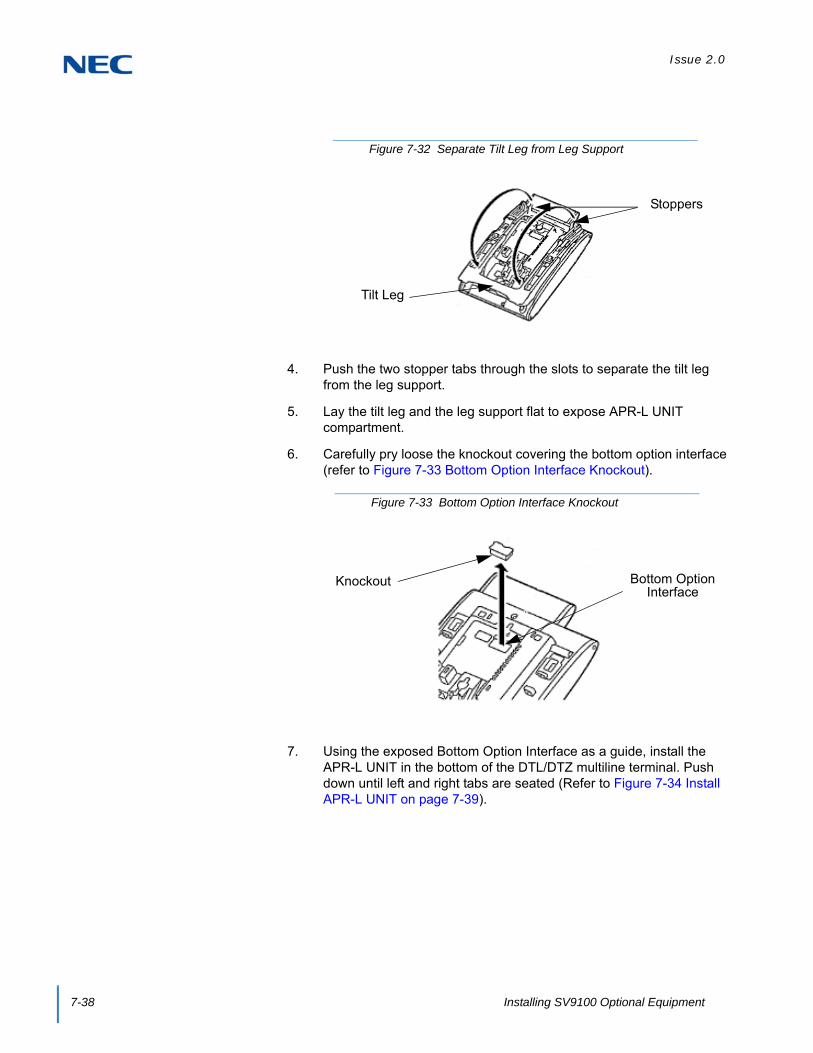
Issue 2.0
7-38 Installing SV9100 Optional Equipment
4. Push the two stopper tabs through the slots to separate the tilt leg from the leg support.
5. Lay the tilt leg and the leg support flat to expose APR-L UNIT compartment.
6. Carefully pry loose the knockout covering the bottom option interface (refer to Figure 7-33 Bottom Option Interface Knockout).
7. Using the exposed Bottom Option Interface as a guide, install the APR-L UNIT in the bottom of the DTL/DTZ multiline terminal. Push down until left and right tabs are seated (Refer to Figure 7-34 Install APR-L UNIT on page 7-39).
Figure 7-32 Separate Tilt Leg from Leg Support
Stoppers
Tilt Leg
Figure 7-33 Bottom Option Interface Knockout
Knockout Bottom Option Interface

Issue 2.0
SV9100 System Hardware Manual 7-39
8. Return tilt leg to original position.
9. For the APR adapter to be recognized correctly, before plugging in the multiline terminal, make sure the extension number to be used for the adapter is undefined in Program 10-03-01.
10. Plug the line cord back into the multiline terminal.
11. To determine the APR analog extension number10-03-04 : Optional Installed Unit 1Display the type of terminal installed. This can be used to verify that the system recognizes the adapter.
10-03-06 : Terminal Type (B2)Assign the terminal type (12) for the telephone channel, which has the APR Adapter installed.
When you want the APR to use the same extension number as the telephone to which it is attached, remove the terminal type in this option. With this setup, when the analog device is in use, it busies out the terminal as there is no separate port number assigned for the adapter. To reverse this, and allow the APR to have its own extension number, reassign the terminal type (12) in this option.
10-03-07 : Logical Port Number (B2) Read Only The port number of the APR Adapter is displayed for the extension (APR ports = 193~512 with all software through 3.07). The ports are assigned from the highest available port down.
Figure 7-34 Install APR-L UNIT
WARNING
To avoid any hardware problems, unplug the line cord, then any other adapter cables, BEFORE REMOVING THE ADAPTER.

Issue 2.0
7-40 Installing SV9100 Optional Equipment
11.5 PSA-L (BK) UNIT / PSA-L (WH) UNIT
The PSA-L UNIT (Power Save Adapter), an optional adapter for the ITL/DTL Terminals, is used with IP telephones to make or receive a call using the Public Switched Telephone Network (PSTN) when a call cannot be made or received using the Local Area Network (LAN). When a power failure occurs, the IP telephone is automatically switched to the PSTN. When power is restored, the IP telephone restarts and connects to the network unless a conversation is in progress on PSTN. The PSTN call must be completed by going on-hook before the connection to the LAN is restored. The unit features:
Survivability in case of power failure or network congestion
Support on modular terminals (ITL/DTL)
PSTN Type = analog PSTN
Dial method – MF/DF (10pps)
Figure 7-35 PSA-L UNIT
User System/PSTN Switch
Volume Control
LEDPSTN

Issue 2.0
SV9100 System Hardware Manual 7-41
11.5.1 Installing the PSA-L Adapter
1. Turn multiline terminal upside down.
2. Unplug the line cord and handset cord from the multiline terminal.
3. Lower the tilt leg to the first position (refer to Figure 7-37 Separate Tilt Leg from Leg Support on page 7-42).
Figure 7-36 PSA-L UNIT Connections
DTMF/DPPSTN
WARNING
BEFORE INSTALLING OR REMOVING the PSA-L adapter, remove the line cord, LAN cable, and then AC adapter from the outlet.
IMPORTANT
Only ONE PSA-L UNIT can be attached to the DTL/ITL multiline terminal.
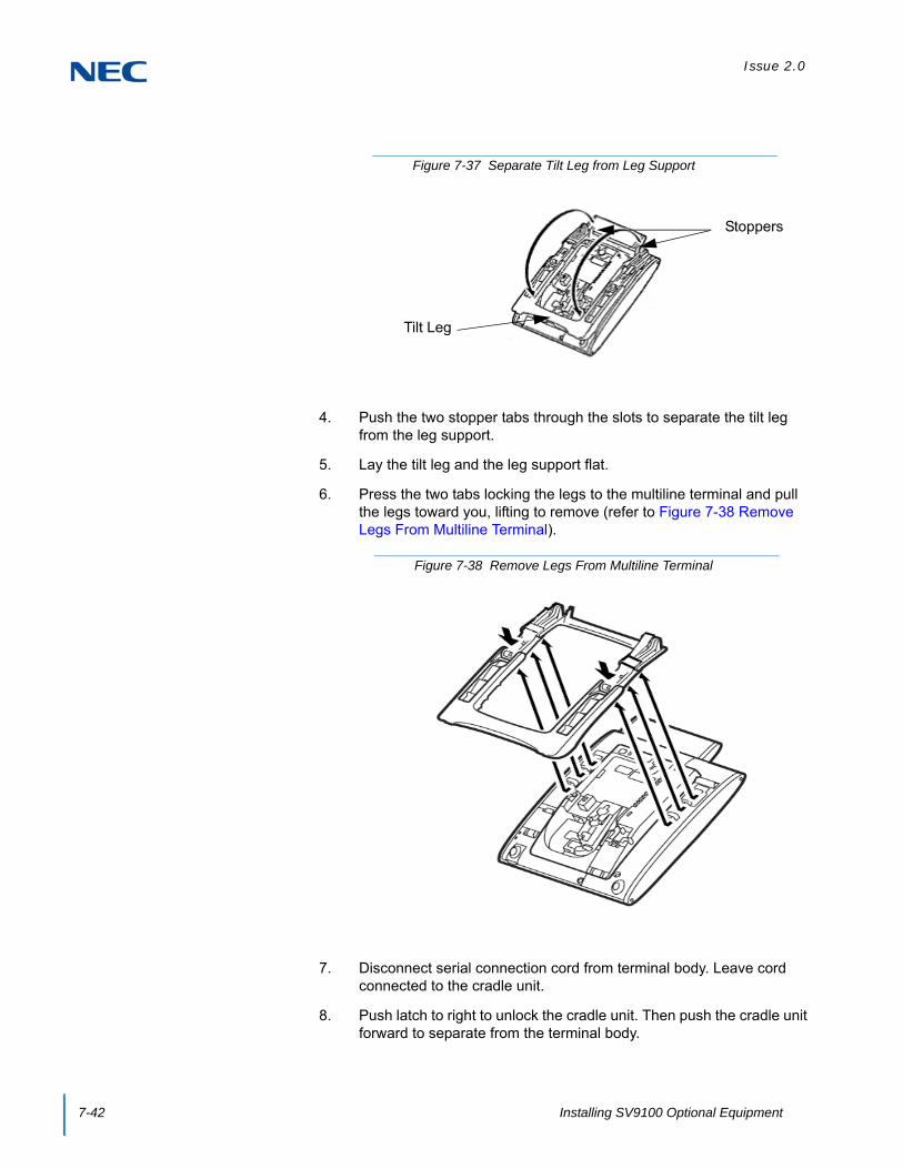
Issue 2.0
7-42 Installing SV9100 Optional Equipment
4. Push the two stopper tabs through the slots to separate the tilt leg from the leg support.
5. Lay the tilt leg and the leg support flat.
6. Press the two tabs locking the legs to the multiline terminal and pull the legs toward you, lifting to remove (refer to Figure 7-38 Remove Legs From Multiline Terminal).
7. Disconnect serial connection cord from terminal body. Leave cord connected to the cradle unit.
8. Push latch to right to unlock the cradle unit. Then push the cradle unit forward to separate from the terminal body.
Figure 7-37 Separate Tilt Leg from Leg Support
Stoppers
Tilt Leg
Figure 7-38 Remove Legs From Multiline Terminal
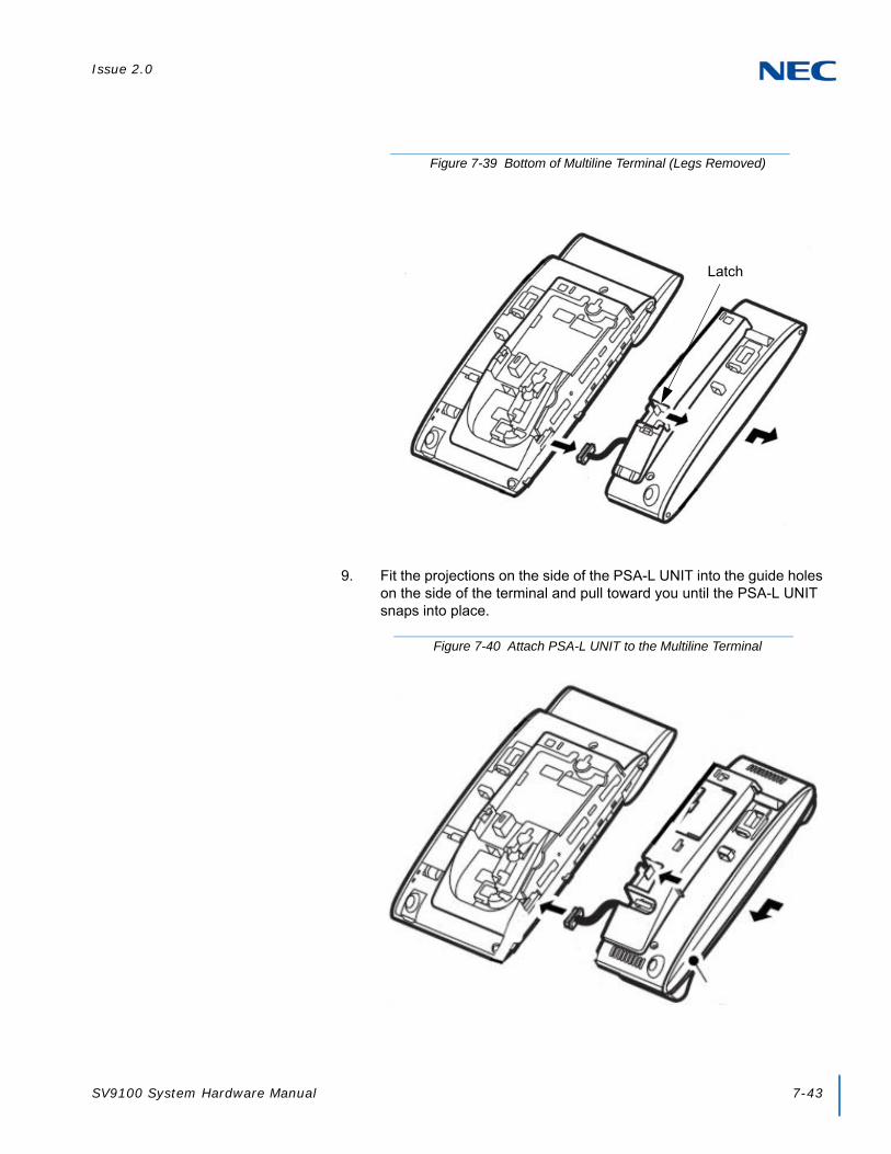
Issue 2.0
SV9100 System Hardware Manual 7-43
9. Fit the projections on the side of the PSA-L UNIT into the guide holes on the side of the terminal and pull toward you until the PSA-L UNIT snaps into place.
Figure 7-39 Bottom of Multiline Terminal (Legs Removed)
Latch
Figure 7-40 Attach PSA-L UNIT to the Multiline Terminal

Issue 2.0
7-44 Installing SV9100 Optional Equipment
10. Gently press the serial cable into the grooved cutout for the cable.
11. Connect the serial connection cord (refer to Figure 7-40 Attach PSA-L UNIT to the Multiline Terminal on page 7-43) from the PSA-L UNIT to the terminal body.
12. Open the Dip Switch Cover (refer to Figure 7-36 PSA-L UNIT Connections on page 7-41). Set the dip switch on the PSA-L adapter to the required position. Close the cover.
13. If using the handset, place the stopper in the tilt leg.
Figure 7-41 Grooved Cutout for Serial Cable
Cable Groove
Figure 7-42 Insert Stopper for Handset Use

Issue 2.0
SV9100 System Hardware Manual 7-45
14. For the Handset, set the connector in place.
15. If using the handset, install the handset cable (refer to Figure 7-44 Insert Handset Cable).
Figure 7-43 Insert Connector for Handset Use
Figure 7-44 Insert Handset Cable

Issue 2.0
7-46 Installing SV9100 Optional Equipment
16. Attach the analog trunk cable and the handset cable. Refer to Figure 7-36 PSA-L UNIT Connections on page 7-41.
17. Install the legs, pushing upwards until both locks snap into place.
18. Return tilt leg to desired position.
19. Place the multiline terminal numbered keypad up.
20. Connect the Line cord, the PSTN cable and the Handset cord (if used).
21. Remove both plastic panels from the front of the multiline terminal.
22. Pull tab down and lift out the numbered keypad panel.
Figure 7-45 Remove Plastic Panels
Figure 7-46 Remove Numbered Keypad

Issue 2.0
SV9100 System Hardware Manual 7-47
23. Install the new keypad panel supplied with the PSA-L UNIT.
24. Install both plastic panels to the front of the multiline terminal (refer to Figure 7-48 Install Plastic Panels).
25. Connect the line cord to the adapter.
26. Connect the user system (KTS or PBX) cable.
27. If required, remove the side panel from the original cradle unit.
Figure 7-47 Install Numbered Keypad
Figure 7-48 Install Plastic Panels

Issue 2.0
7-48 Installing SV9100 Optional Equipment
11.5.2 Using the PSA-L Adapter
1. Placing Calls:When the PSTN line is activated either manually by the switch or due to a power failure, use the dial pad buttons (0-9, *, #) to place an outside call. Use the Vol or to increase or decrease audio levels.
Other than receiving calls, no other multiline terminal function is available.
2. Answering Calls:
If you receive a call via PSTN during a conversation via LAN, answer the call by completing the LAN call and placing the handset back into the cradle. Change the LAN/PSTN Change Switch to PSTN and then lift the handset to answer the call. If you change the LAN/PSTN Change Switch to the PSTN position while talking via LAN, the LAN call is disconnected.
Other than receiving calls, no other terminal function is available.
3. Adjusting the Ring VolumeUse the Volume Control Switch located on the PSA-L adapter to adjust through the three available volume levels.
Other than receiving calls, no other terminal function is available.
4. When Power is RestoredThe IP multiline terminal restarts and reconnects to the network LAN. However, if you are on a PSTN call when the power is restored, your conversation continues until the handset is placed in the cradle. Once this occurs, the IP terminal restarts and reconnects to the LAN.
Other than receiving calls, no other terminal function is available.
WARNING
BEFORE INSTALLING OR REMOVING the PSA-L adapter, remove the line cord, LAN cable, and then AC adapter from the outlet.

Issue 2.0
SV9100 System Hardware Manual 7-49
11.6 Gigabit Adapter (GBA-L UNIT)
The GBA-L UNIT enables IP telephones (DT730/DT750) to operate in a Gigabit Ethernet environment. A single Gigabit Ethernet desktop drop provides a 10/100Mbps to the IP telephone and a gigabit connection to a personal computer. The Gigabit Adapter is installed on the bottom of the IP telephone and offers a gigabit interface to the LAN side and PC port. The Gigabit Adapter is powered by PoE or can operate off of local power.
11.6.1 Installing the GBA-L UNIT
1. Turn multiline terminal upside down.
2. Unplug the line cord and handset cord from the multiline terminal.
Figure 7-49 GBA-L UNIT
WARNING
BEFORE INSTALLING OR REMOVING the GBA-L UNIT, remove the line cord, LAN cable, and then AC adapter from the outlet.
IMPORTANT
Only ONE GBA-L UNIT can be attached to the DTL/ITL multiline terminal.

Issue 2.0
7-50 Installing SV9100 Optional Equipment
3. Lower the tilt leg to the first position (refer to Figure 7-50 Separate Tilt Leg from Leg Support).
4. Push the two stopper tabs through the slots to separate the tilt leg from the leg support.
5. Lay the tilt leg and the leg support flat.
6. Press the two tabs locking the legs to the multiline terminal and pull the legs toward you, lifting to remove (refer to Figure 7-51 Remove Legs From Multiline Terminal).
Figure 7-50 Separate Tilt Leg from Leg Support
Stoppers
Tilt Leg
Figure 7-51 Remove Legs From Multiline Terminal

Issue 2.0
SV9100 System Hardware Manual 7-51
7. Plug in the LAN cable and gently press the cable into the grooved cutout (refer to Figure 7-52 Attach the LAN Cable).
8. Plug in the DC power cable and gently press the cable into the grooved cutout (refer to Figure 7-53 Attach the DC Power Cable).
Figure 7-52 Attach the LAN Cable
Figure 7-53 Attach the DC Power Cable
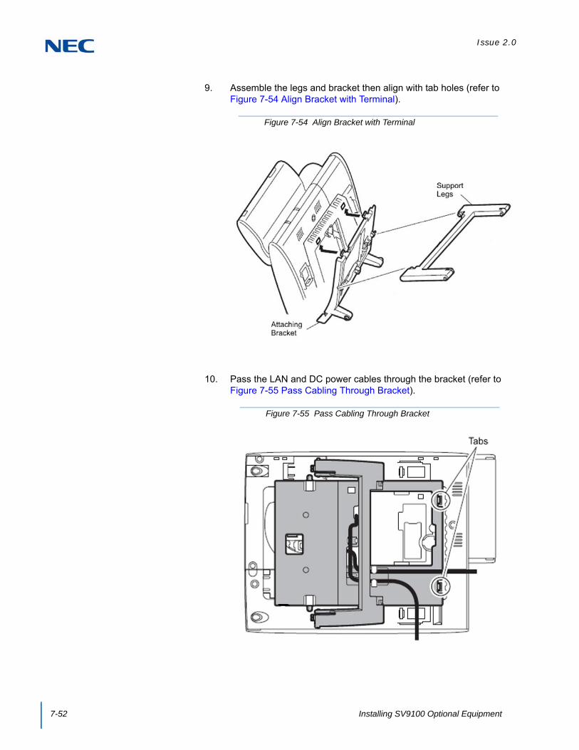
Issue 2.0
7-52 Installing SV9100 Optional Equipment
9. Assemble the legs and bracket then align with tab holes (refer to Figure 7-54 Align Bracket with Terminal).
10. Pass the LAN and DC power cables through the bracket (refer to Figure 7-55 Pass Cabling Through Bracket).
Figure 7-54 Align Bracket with Terminal
Figure 7-55 Pass Cabling Through Bracket

Issue 2.0
SV9100 System Hardware Manual 7-53
11. Slide the supporting bracket forward until a click is heard (refer to Figure 7-56 Secure Bracket to Terminal).
12. Secure base of GBA-L UNIT to bracket assembly (refer to Figure 7-57 Secure GBA-L UNIT Base to Bracket Assembly).
Figure 7-56 Secure Bracket to Terminal
Figure 7-57 Secure GBA-L UNIT Base to Bracket Assembly

Issue 2.0
7-54 Installing SV9100 Optional Equipment
13. Install the NEC provided Cat 5 Ethernet cable (refer to Figure 7-58 IP Phone(X) Connection).
14. Install the NEC provided Cat 5 Ethernet cable (refer to Figure 7-59 PC(X) Connection).
Figure 7-58 IP Phone(X) Connection
Figure 7-59 PC(X) Connection
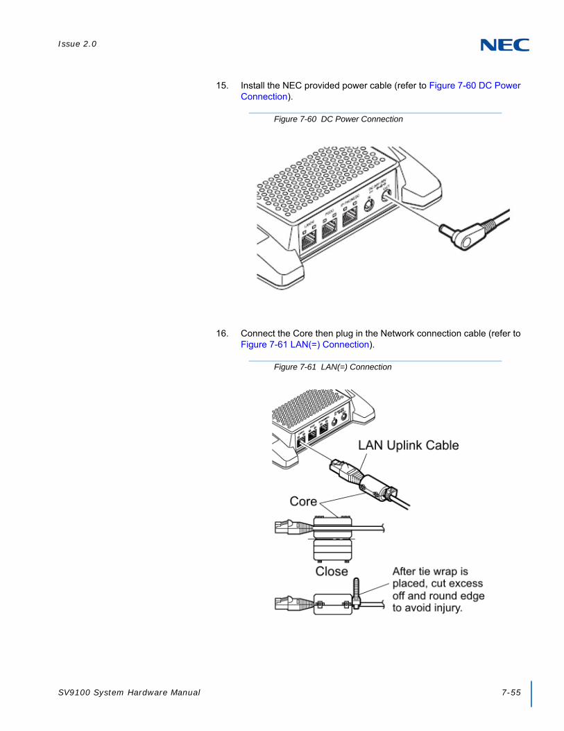
Issue 2.0
SV9100 System Hardware Manual 7-55
15. Install the NEC provided power cable (refer to Figure 7-60 DC Power Connection).
16. Connect the Core then plug in the Network connection cable (refer to Figure 7-61 LAN(=) Connection).
Figure 7-60 DC Power Connection
Figure 7-61 LAN(=) Connection

Issue 2.0
7-56 Installing SV9100 Optional Equipment
17. Install the cable from the optional external AC adapter (refer to Figure 7-62 AC to DC In Connection).
18. Cable installation for the GBA-L UNIT complete (refer to Figure 7-63 GBA-L UNIT Installed).
IMPORTANT
The AC Adapter (AC-L UNIT) must be ordered separately.
Figure 7-62 AC to DC In Connection
Figure 7-63 GBA-L UNIT Installed

Issue 2.0
SV9100 System Hardware Manual 7-57
11.6.2 GBA-L UNIT Connection
The following chart outlines the connectivity available to the GBA-L UNIT:
11.6.3 LED Display
The following provides a list of each LED and associated operation and status indications. Refer to Figure 7-65 GBA-L UNIT LED Display on page 7-58 for the location of the LEDs on the GBA-L UNIT.
Figure 7-64 GBA-L UNIT Connectivity Chart

Issue 2.0
7-58 Installing SV9100 Optional Equipment
SECTION 12 POWER FAILURE TELEPHONES
12.1 Power Failure
The system allows connection for basic telephone service during a power failure. The power failure operation occurs during a commercial power failure, and is not affected by blade failure. Power Failure Transfer is provided by connecting to the GCD-4COT( ) blade.
The GCD-4COT( ) Blade provides 2 Power Failure Transfer circuits.
The CN3 and CN5 connectors each provide connection to four analog trunk ports, which are polarity sensitive (tip to tip, ring to ring). The power failure circuits, however, are not polarity sensitive. A maximum of 15 GCD-4COT( ) blades per system is allowed.
Figure 7-65 GBA-L UNIT LED Display
LED NameWhen 1000Mbps is
ConnectedWhen 100Mbps is
ConnectedWhen 10Mbps is
Connected
SPEED Display Green Lighting Red Lighting Turning Off
LED Name At LINKACT
(At the Data Communication)
LINK/ACT Display Green Lighting Green Blinking
CAUTION
When connecting the RJ-61 cables to the COIU Blade, note the position of the Power Failure connector.
Do not confuse connector CN3 as the CN2 trunk connector.

Issue 2.0
SV9100 System Hardware Manual 7-59
12.2 Connector Pin-Outs on COIU Blade for Power Failure Circuits
Table 7-5 RJ-61 Cable Connectorprovides the pin-outs for the RJ-61 cable connector.
12.3 Installing the Power Failure Telephones
1. Connect an RJ-61 connector to the COIU Blade installed in the system.
2. Install a modular jack for each single line telephone supporting PF operation. The modular jack should be within six feet of the phone.
3. For each extension, run one-pair 24 AWG station cable from the cross-connect block to a modular jack.
4. Terminate the extension leads to GRN/RED of the modular jack. Terminate the unused leads to the jack. Refer to Figure 7-66 Power Failure Connector (CN3) Shown on GCD-4COT( ) Blade.
Table 7-5 RJ-61 Cable Connector
RJ-61 Cable Connector - CN13, SLT Interface for Power Failure
Pin No. Connection
1 –
2 –
3 Circuit 2 - Tip
4 Circuit 1 - Ring
5 Circuit 1 - Tip
6 Circuit 2 - Ring
7 –
8 –

Issue 2.0
7-60 Installing SV9100 Optional Equipment
SECTION 13 IP VIDEO DOORPHONE
IP Video Doorphone tables has been saved in: SV9100_IP Video Doorphone Equip - SAVE file
Figure 7-66 Power Failure Connector (CN3) Shown on GCD-4COT( ) Blade

Issue 2.0
SV9100 System Hardware Manual 7-61
13.1 Connection Image
The IP Video Doorphone (IP3NE-IPCDH) connects with the IPLE via the PoE Switch(IEEE802.3af). The system can support a maximum of eight doorphones, which are shared between the video and 2PGDAD doorphones.
13.1.1 Local Setting (Web Setting)
Local Setting of the IP Video Doorphone is completed using a PoE Switch and PC for the following connections.
IMPORTANT
The IP Video Doorphone port requires both a door phone and SIP extension port. If the extension port is not available, the IP Video Doorphone can not be connected.
Figure 7-67 IP Video Doorphone Configuration

Issue 2.0
7-62 Installing SV9100 Optional Equipment
13.1.2 System Connections
Connect the IP Video Doorphone and IPLE via the PoE Switch. The image view of the IP Video Doorphone is displayed in the PC using DR-Viewer or can be displayed on a Polycom VVX1500 terminal.
13.2 IP Video Doorphone and Options
IP Video Doorphone (IP3NE-IPCDH) and available options are described in this section.
Figure 7-68 IP Video Doorphone and SV9100 Configuration
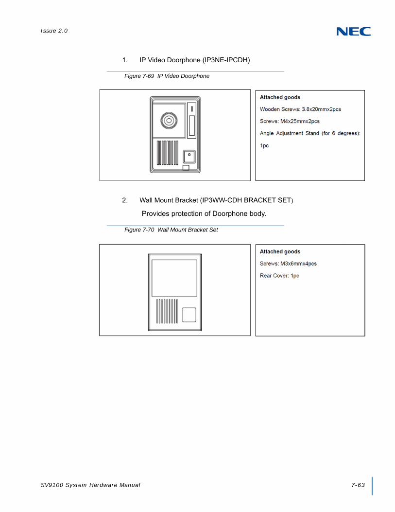
Issue 2.0
SV9100 System Hardware Manual 7-63
1. IP Video Doorphone (IP3NE-IPCDH)
2. Wall Mount Bracket (IP3WW-CDH BRACKET SET)
Provides protection of Doorphone body.
Figure 7-69 IP Video Doorphone
Figure 7-70 Wall Mount Bracket Set

Issue 2.0
7-64 Installing SV9100 Optional Equipment
3. Wall Cover (IP3WW-CDH WALL COVER SET)
Used for flush mount of the Doorphone body.
Figure 7-71 Wall Cover Set

Issue 2.0
SV9100 System Hardware Manual 7-65
13.3 Location of Controls
Figure 7-72 IP Doorphone Controls

Issue 2.0
7-66 Installing SV9100 Optional Equipment
13.4 Before Installing the IP Video Doorphone
13.4.1 Precautionary Information
Do not use a metal-tipped (i.e. screwdriver) device when opening the doorphone unit. An electric shock or fire may occur.
If the Doorphone emits either smoke or a burning, acrid odor, immediately disconnect the LAN Cable from the Doorphone. Operating the Doorphone in this state might cause a fire, an electrical shock or a system failure. Disconnect the LAN Cable and after confirming that the smoke has disappeared, contact the dealer.
13.4.2 Installation Information
The range of focus is depicted below.
WARNING
Observe the following warnings during installation:
Power off the PoE Switch (PoE feeding 48V) during installation, and disconnect the LAN cable from the PoE Switch – Electric shock may occur.
Do not connect /disconnect the LAN cable if hands are wet – Electric shock may occur.
Figure 7-73 Range of Focus

Issue 2.0
SV9100 System Hardware Manual 7-67
When attaching the IP Video Doorphone to a wall, recommend the upper, right and left sides be sealed using a water resistant agent such as silicon.
Do not seal the lower part of the unit, the drain hole on the bottom must be kept open.
Figure 7-74 Angle of View
Figure 7-75 Viewing Field by Height
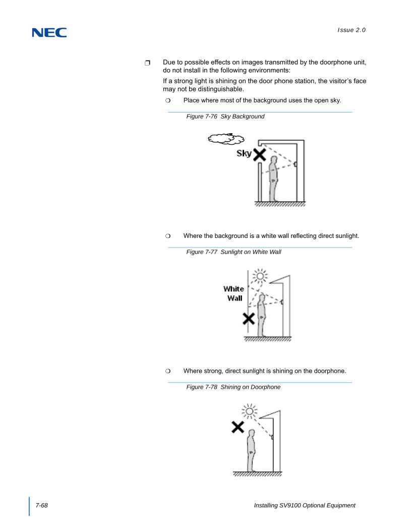
Issue 2.0
7-68 Installing SV9100 Optional Equipment
Due to possible effects on images transmitted by the doorphone unit, do not install in the following environments:
If a strong light is shining on the door phone station, the visitor’s face may not be distinguishable.
Place where most of the background uses the open sky.
Where the background is a white wall reflecting direct sunlight.
Where strong, direct sunlight is shining on the doorphone.
Figure 7-76 Sky Background
Figure 7-77 Sunlight on White Wall
Figure 7-78 Shining on Doorphone

Issue 2.0
SV9100 System Hardware Manual 7-69
For a clearer image during night time viewing, install lighting equipment near the Video Doorphone.
.
13.4.3 General Precautions
1. To avoid shock or equipment damage, do not plug in or turn the system power on before completing the installation process.
2. Avoid working with the equipment during electrical storms.
3. Never install Doorphone wiring during a lightning storm.
4. Avoid parallel wiring with a power line, a TV antenna line and a FM antenna line.
5. Do not secure the cable using a stapler. Wiring may become damaged and short-circuit.
6. Avoid running cable beneath a carpet.
7. Do not run a cable under a desk or a cabinet.
8. Use Wire Protector when cables are run across the floor.
13.4.4 Site Requirements
Meeting established environmental standards maximizes the life of the Doorphone. Make sure that the site is not:
1. In strong, direct sunlight or in extremely hot, cold or humid places.
2. In dusty areas or in areas where sulfuric gases are produced.
3. In places where shocks or vibrations are frequent or strong.
Figure 7-79 Lighting Equipment
TIP
When the door phone is used for room monitor, do not install the extension terminals near the door phone, feedback may be present

Issue 2.0
7-70 Installing SV9100 Optional Equipment
4. In places where water or other fluids comes in contact with the equipment.
5. In areas near high-frequency machines or electric welders.
6. Near radio antennas (including shortwave).
13.4.5 Powering On the IP Video Doorphone
1. When powering on the Doorphone, it may take up to 60 seconds until a doorphone starts. The Power lamp will begin blinking. When the lamp turns solid, the Doorphone is available.
2. If the Power lamp continues blinking for more than 70 seconds, the authentication to the main device may have failed. Reset the doorphone to attempt authentication again.
13.5 Installation
13.5.1 Connect a Door Unlock Device to the IP Video Doorphone
Connecting the Door Unlock Device to an IP Video Doorphone (using Relay contacts):
1. When the Unlock Device Relay output is normally closed. The 2-wire cable is connected the C and NC terminals.
2. When the Unlock Device Relay output is normally open. The 2-wire cable is connected to the C and NO terminals.
Figure 7-80 C and NC Terminal Connections
Figure 7-81 C and NO Terminal Connections
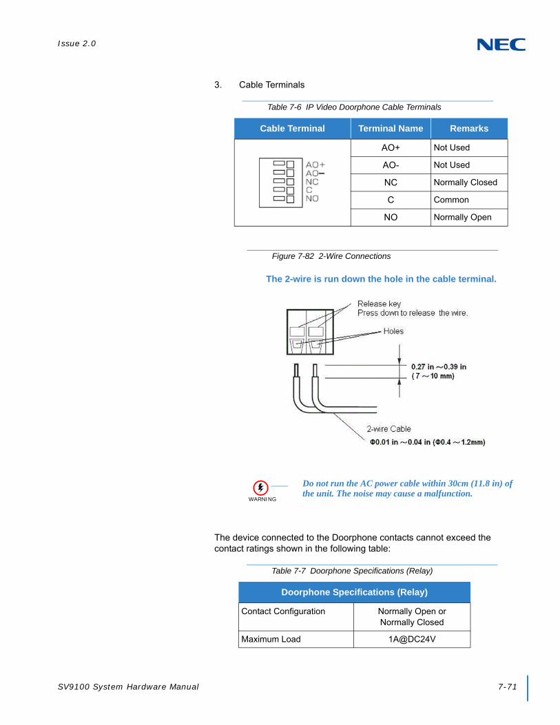
Issue 2.0
SV9100 System Hardware Manual 7-71
3. Cable Terminals
The device connected to the Doorphone contacts cannot exceed the contact ratings shown in the following table:
Table 7-6 IP Video Doorphone Cable Terminals
Cable Terminal Terminal Name Remarks
AO+ Not Used
AO- Not Used
NC Normally Closed
C Common
NO Normally Open
Figure 7-82 2-Wire Connections
The 2-wire is run down the hole in the cable terminal.
WARNING
Do not run the AC power cable within 30cm (11.8 in) of the unit. The noise may cause a malfunction.
Table 7-7 Doorphone Specifications (Relay)
Doorphone Specifications (Relay)
Contact Configuration Normally Open orNormally Closed
Maximum Load 1A@DC24V

Issue 2.0
7-72 Installing SV9100 Optional Equipment
The system can support a maximum of eight door stations (including the normal Door box). Refer to the following table for specifications of the IP Video Doorphone.
Table 7-8 IP Video Doorphone Specifications
Item Specification
Power Supply
Feeding System PoE (48V) IEEE802.3af
Power Consumption 5W or less
Maximum Cable Length 100m or less
Temperature and HumidityOperating Temperature and Humidity -10oC ~ +45oC 90% or less (non-condensing)
Storage Temperature and Humidity -20oC ~ +60oC 90% or less (non-condensing)
Mechanical Specification
Dimensions (WxDxH) 100×150×53.5mm
Weight 320g
Water Proof JIS IPX3 (Rain proof type)
EMI Standard FCC Class-B
Camera
Image Sensor 1/4 type CCD 0.25 mega-pixel
Angle of View Wide Angle Type,Horizontal direction = 102 degreesVertical direction = 76 degrees
Image Compression H.264 or MJPEG
Voice Compression Method G.711 μ-law/A-law
Interface
LAN 10BASE-T/100BASE-TXAuto NegotiationAuto MDI/MDI-X
External Relay Output Non-voltage contact output×1Rating value : DC24V/1A or less
External Line Output External Speaker Output×1Output Impedance : 600Ω

Issue 2.0
SV9100 System Hardware Manual 7-73
13.5.2 Adjusting the Camera Angle
Adjustment of the camera is made using an angle adjustment lever in the backside of the Doorphone (camera part).
1. The angle of the camera can be adjusted approximately 15 degrees to each side (upper, right and left). Adjust the visitor image to a position than can be easily viewed.
2. When adjusting the camera upward, turn the lever downward. If moving the camera to the left, the lever turn to the left, likewise, if moving the camera to the right, turn the lever to the right.
3. For adjusting the camera angle, the lever position should be moved towards the desired edge. Otherwise the lever may slip off at the time of installation.
When the Camera angle is being adjusted upward, the Angle Adjustment Stand can be installed.
Fit the Angle Adjustment Stand no more than six degrees from the mounting bracket. (Installation of screws is not required.)
Installing the Doorphone unit is a simple operation.
The main body of the Doorphone points upward six degrees.
The Doorphone can adjust to 21 degrees, when using an up angle adjustment (6 degrees) together with a camera angle adjustment function (15 degrees) from the main body.
Figure 7-83 Camera Angle Adjustment Lever

Issue 2.0
7-74 Installing SV9100 Optional Equipment
To disassemble the Angle Adjustment Stand, press down on the Mounting Bracket and pull up on the Angle Adjustment Stand at the same time.
Figure 7-84 Angle Adjustment Stand
Figure 7-85 Disassemble Angle Adjustment Stand

Issue 2.0
SV9100 System Hardware Manual 7-75
13.5.3 Installing the IP Video Doorphone
When installing the Doorphone, the Mounting Bracket, screw and screw cover can be removed and installed using the following procedure:
1. The Bracket is mounted to the Wall Mounting Plate (on the wall) using two wood screws (3.8x20mm) or two M4x25mm screws.
2. Connect LAN cable to the LAN Connector from the PoE Switch.
3. Insert the Bracket tab into the slot on top of the Main body.
4. Secure Main body and Mounting Bracket with the retaining screw.
Figure 7-86 Installing the IP Video Doorphone
NOTE
The Mounting Bracket, Screw and Screw Cover are attached to the Doorphone Main Body.
The Wall Mounting Plate is purchased locally by the user.

Issue 2.0
7-76 Installing SV9100 Optional Equipment
5. Mount the Screw Cover.
13.5.4 Installing the IP Video Doorphone Using a Wall Mount Bracket (IP3WW-CDH BRACKET SET)
This section describes how to install the IP Video Doorphone using a Wall Mount Bracket.
1. Loosen the Main Body fixed screw and remove the Main Body from the Mounting Bracket.
2. The Rear Cover is mounted to the Wall Mounting Plate (on the wall) using two wood screws (3.8x20mm) or M4x25mm screws.
3. Insert the Bracket tab into the top of the Rear Cover.
4. Secure the Main Body and Rear Cover with the retaining screw.
5. Mount the Screw Cover.
TIP
When there is a gap between the Wall Mounting Plate (on the wall) and the Bracket, the Bracket may be warped due to an over-tightened screw. Simply loosen the screw.
Figure 7-87 Installing the IP Video Doorphone Using Wall Mount Bracket Set
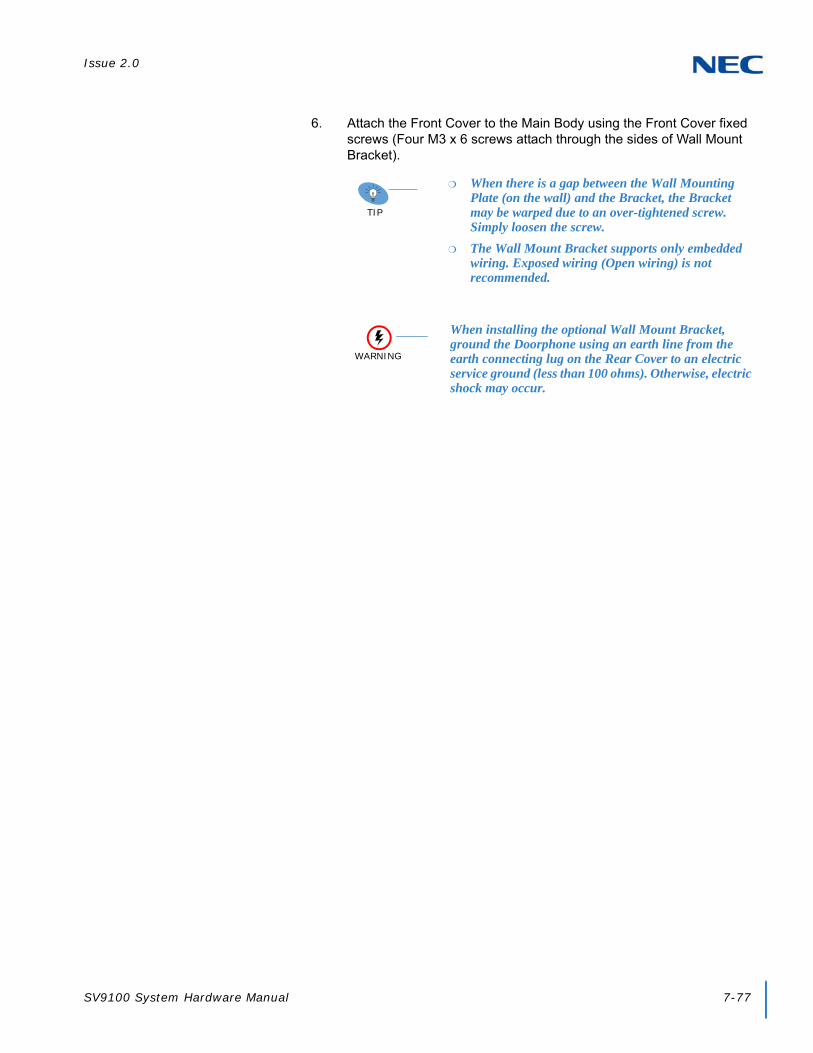
Issue 2.0
SV9100 System Hardware Manual 7-77
6. Attach the Front Cover to the Main Body using the Front Cover fixed screws (Four M3 x 6 screws attach through the sides of Wall Mount Bracket).
TIP
When there is a gap between the Wall Mounting Plate (on the wall) and the Bracket, the Bracket may be warped due to an over-tightened screw. Simply loosen the screw.
The Wall Mount Bracket supports only embedded wiring. Exposed wiring (Open wiring) is not recommended.
WARNING
When installing the optional Wall Mount Bracket, ground the Doorphone using an earth line from the earth connecting lug on the Rear Cover to an electric service ground (less than 100 ohms). Otherwise, electric shock may occur.

Issue 2.0
7-78 Installing SV9100 Optional Equipment
13.5.5 Installing the IP Video Doorphone Using a Wall Cover Set (IP3WW-CDH WALL COVER SET)
This section describes how to install the IP Video Doorphone using a Wall Cover Set.
1. The Rear Bracket is mounted to the Mounting Bracket using Rear Bracket fixed screws (four M3x6mm screws).
2. Insert the Bracket tab into the slot on top of the Main Body.
3. Secure the Main Body and Mounting Bracket with the retaining screws.
4. Mount the Screw Cover.
Figure 7-88 Installing the IP Video Doorphone Using Wall Cover Set

Issue 2.0
SV9100 System Hardware Manual 7-79
5. Secure the Front Cover to the Main body using the Front Cover fixed screw (four M3 x 6 screws attached with Wall Cover).
TIP
When the Front Cover is mounted to the wall, the Front Cover may be warped due to an over-tightened screw. Simply loosen the screw.
The Wall Cover Set supports only embedded wiring. Exposed wiring (Open wiring) is not recommended.
WARNING
When installing the optional Wall Mount Bracket, ground the Doorphone using an earth line from the earth connecting lug on the Rear Cover to an electric service ground (less than 100 ohms). Otherwise, electric shock may occur.

System Hardware Manual
NEC CorporationIssue 2.0
SV9100®
Related Documents


