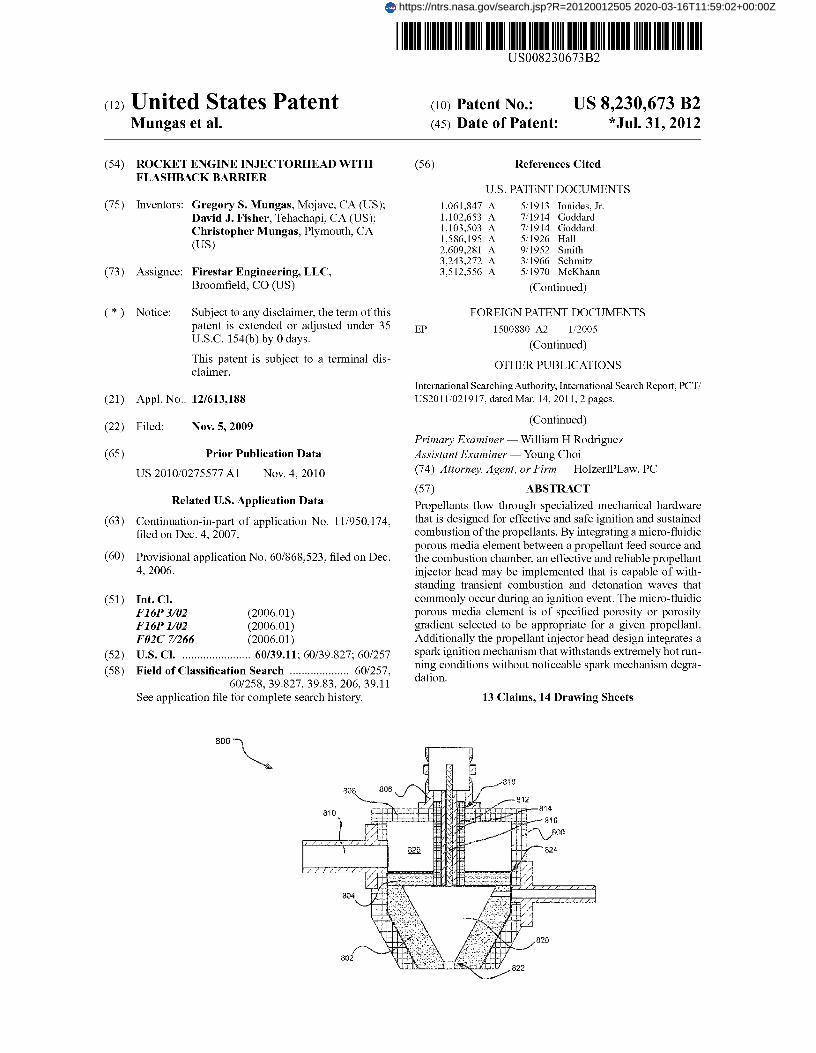
(12) United States Patent Mungas et al. (54) ROCKET ENGINE INJECTORHEAD WITH FLASHBACK BARRIER (75) Inventors: Gregory S. Mungas, Mojave, CA (US); David J. Fisher, Tehachapi, CA (US); Christopher Mungas, Plymouth, CA (US) (73) Assignee: Firestar Engineering, LLC, Broomfield, CO (US) (*) Notice: Subject to any disclaimer, the term of this patent is extended or adjusted under 35 U.S.C. 154(b) by 0 days. This patent is subject to a terminal dis- claimer. (21) Appl. No.: 12/613,188 (22) Filed: Nov. 5, 2009 (65) Prior Publication Data US 2010/0275577 Al Nov. 4, 2010 Related U.S. Application Data (63) Continuation-in-part of application No. 11/950,174, filed on Dec. 4, 2007. (60) Provisional application No. 60/868,523, filed on Dec. 4, 2006. (51) Int. Cl. F16P3102 (2006.01) F16P1102 (2006.01) F02C 71266 (2006.01) (52) U.S. Cl . ....................... 60/39.11; 60/39.827; 60/257 (58) Field of Classification Search .................... 60/257, 60/258, 39.827, 39.83, 206, 39.11 See application file for complete search history. (1o) Patent No.: US 8,230,673 B2 (45) Date of Patent: *Jul. 31 9 2012 (56) References Cited U.S. PATENT DOCUMENTS 1,061,847 A 5/1913 Ionides, Jr. 1,102,653 A 7/1914 Goddard 1,103,503 A 7/1914 Goddard 1,586,195 A 5/1926 Hall 2,609,281 A 9/1952 Smith 3,243,272 A 3/1966 Schmitz 3,512,556 A 5/1970 McKhann (Continued) FOREIGN PATENT DOCUMENTS EP 1500880 A2 1/2005 (Continued) OTHER PUBLICATIONS International Searching Authority, International Search Report, PCT/ US2011/021917, dated Mar. 14, 2011, 2 pages. (Continued) Primary Examiner William H Rodriguez Assistant Examiner Young Choi (74) Attorney, Agent, or Firm HolzerIPLaw, PC (57) ABSTRACT Propellants flow through specialized mechanical hardware that is designed for effective and safe ignition and sustained combustion of the propellants. By integrating a micro-fluidic porous media element between a propellant feed source and the combustion chamber, an effective and reliable propellant injector head may be implemented that is capable of with- standing transient combustion and detonation waves that commonly occur during an ignition event. The micro-fluidic porous media element is of specified porosity or porosity gradient selected to be appropriate for a given propellant. Additionally the propellant injector head design integrates a spark ignition mechanism that withstands extremely hot run- ning conditions without noticeable spark mechanism degra- dation. 13 Claims, 14 Drawing Sheets 800 https://ntrs.nasa.gov/search.jsp?R=20120012505 2020-03-16T11:59:02+00:00Z

Welcome message from author
This document is posted to help you gain knowledge. Please leave a comment to let me know what you think about it! Share it to your friends and learn new things together.
Transcript
(12) United States Patent Mungas et al.
(54) ROCKET ENGINE INJECTORHEAD WITH FLASHBACK BARRIER
(75) Inventors: Gregory S. Mungas, Mojave, CA (US); David J. Fisher, Tehachapi, CA (US); Christopher Mungas, Plymouth, CA (US)
(73) Assignee: Firestar Engineering, LLC, Broomfield, CO (US)
(*) Notice: Subject to any disclaimer, the term of this patent is extended or adjusted under 35 U.S.C. 154(b) by 0 days.
This patent is subject to a terminal dis-claimer.
(21) Appl. No.: 12/613,188
(22) Filed: Nov. 5, 2009
(65) Prior Publication Data
US 2010/0275577 Al Nov. 4, 2010
Related U.S. Application Data
(63) Continuation-in-part of application No. 11/950,174, filed on Dec. 4, 2007.
(60) Provisional application No. 60/868,523, filed on Dec. 4, 2006.
(51) Int. Cl. F16P3102 (2006.01) F16P1102 (2006.01) F02C 71266 (2006.01)
(52) U.S. Cl . ....................... 60/39.11; 60/39.827; 60/257
(58) Field of Classification Search .................... 60/257, 60/258, 39.827, 39.83, 206, 39.11
See application file for complete search history.
(1o) Patent No.: US 8,230,673 B2 (45) Date of Patent: *Jul. 31 9 2012
(56) References Cited
U.S. PATENT DOCUMENTS
1,061,847 A 5/1913 Ionides, Jr. 1,102,653 A 7/1914 Goddard 1,103,503 A 7/1914 Goddard 1,586,195 A 5/1926 Hall 2,609,281 A 9/1952 Smith 3,243,272 A 3/1966 Schmitz 3,512,556 A 5/1970 McKhann
(Continued)
FOREIGN PATENT DOCUMENTS
EP 1500880 A2 1/2005
(Continued)
OTHER PUBLICATIONS
International Searching Authority, International Search Report, PCT/ US2011/021917, dated Mar. 14, 2011, 2 pages.
(Continued)
Primary Examiner William H Rodriguez Assistant Examiner Young Choi (74) Attorney, Agent, or Firm HolzerIPLaw, PC
(57) ABSTRACT
Propellants flow through specialized mechanical hardware that is designed for effective and safe ignition and sustained combustion of the propellants. By integrating a micro-fluidic porous media element between a propellant feed source and the combustion chamber, an effective and reliable propellant injector head may be implemented that is capable of with-standing transient combustion and detonation waves that commonly occur during an ignition event. The micro-fluidic porous media element is of specified porosity or porosity gradient selected to be appropriate for a given propellant. Additionally the propellant injector head design integrates a spark ignition mechanism that withstands extremely hot run-ning conditions without noticeable spark mechanism degra-dation.
13 Claims, 14 Drawing Sheets
800
https://ntrs.nasa.gov/search.jsp?R=20120012505 2020-03-16T11:59:02+00:00Z
US 8,230,673 B2 Page 2
U.S. PATENT DOCUMENTS
3,719,046 A * 3/1973 Sutherland et al . ............. 60/206 3,779,714 A 12/1973 Nadkarni et al. 4,045,159 A * 8/1977 Nishi et al ..................... 431/328 4,398,527 A 8/1983 Rynbrandt 4,446,351 A 5/1984 Kawaguchi et al. 4,458,595 A 7/1984 Gerrish, Jr. et al. 4,703,620 A 11/1987 Niino et al. 4,707,184 A 11/1987 Hashiguchi et al. 4,736,676 A 4/1988 Taylor 5,203,296 A 4/1993 Hart 5,305,726 A 4/1994 Scharman et al. 5,466,313 A 11/1995 Brede et al. 5,477,613 A 12/1995 Bales et al. 5,608,179 A 3/1997 Voecksetal. 5,738,061 A 4/1998 Kawamura 5,768,885 A 6/1998 Johnson et al. 5,855,827 A 1/1999 Bussing et al. 6,047,541 A 4/2000 Hampsten 6,151,887 A 11/2000 Haidn et al. 6,179,608 B1 1/2001 Kraemer et al. 6,336,318 B1 * 1/2002 Falce et al ....................... 60/202 6,606,851 B1 8/2003 Herdy, Jr. et al. 6,779,335 B2 8/2004 Herdy, Jr. et al. 6,799,417 B2 10/2004 Hewitt 6,834,504 B2 * 12/2004 Griffin et al . ................... 60/737 6,895,743 B1 5/2005 McElheran et al. 6,896,512 B2 5/2005 Rattner et al. 6,915,834 B2 7/2005 Knott et al. 6,984,273 B1 1/2006 Martin et al. 7,056,114 B2 6/2006 Brooker 7,124,574 B2 10/2006 Horn et al. 7,241,137 B2 * 7/2007 Leinemann et al. .......... 431/346 7,370,469 B2 5/2008 Watkins 7,377,948 B2 5/2008 Faris 7,418,814 B1 9/2008 Greene 7,451,751 B2 11/2008 Atherley 7,475,561 B2 1/2009 Smolko et al. 7,585,381 B1 9/2009 Zubrin
2004/0055277 Al 3/2004 Kline et al. 2004/0081783 Al * 4/2004 Prince .......................... 428/36.9 2004/0253624 Al* 12/2004 Smith et al ........................ 435/6 2006/0121080 Al 6/2006 Lye et al. 2007/0169461 Al 7/2007 Koerner 2008/0173020 Al 7/2008 Mungas et al. 2008/0209872 Al 9/2008 Samaras et al. 2009/0071434 Al 3/2009 MacMillan et al. 2009/0120060 Al* 5/2009 Coste .............................. 60/257 2009/0126514 Al* 5/2009 Burroughs et al. ........ 73/863.22 2009/0266049 Al* 10/2009 Mittendorf ...................... 60/204
FOREIGN PATENT DOCUMENTS
GB 1029894 5/1996 WO 0151433 Al 7/2001 WO 03028069 A2 4/2003 WO 2004089564 Al 10/2004 WO 2005037467 A2 4/2005 WO 2007052084 Al 5/2007
OTHER PUBLICATIONS
International Searching Authority, Written Opinion, PCT/US201I/ 021917, dated Mar. 14, 2011, 7 pages. "aRocket", an amateurrocketry discussion forum onhttp://exrocktry. net/mailman/listinfo/arocket, Dec. 31, 2009. Balasubramanyam, M.S. et al., "Catalytic Ignition of Nitrous Oxide with Propane/Propylene Mixtures for Rocket Motors," 41st AIAA/ ASME/SAE/ASEE Joint Propulsion Conference & Exhibit, Jul. 10-13, 2005, Tucson, AZ, AIAA Paper No. AIAA 2005-3919, pp. 1-8. Boysan, M.E. et al., "Comparison of Different Aspect Ratio Cooling Channel Designs for a Liquid Propellant Rocket Engine," Recent Advances in Space Technologies, 2007, RAST '07, 3rd International Conference, pp. 225-230/. Burkhardt, W.M. et al., Abstract "Formed platelets for low cost regeneratively cooled rocket combustion chambers," AIAA, SAE, ASME, and ASEE, Joint Propulsion Conference and Exhibit, 28th,
Nashville, TN, Jul. 6-8, 1992, SAO/NASA ADS Physics Abstract Service, http://adsabs.harvafd.edu/abs/1992jpnt.confRT...B, 2 pages. Dong (Kenn) Kim et al., "Characterization/Modeling of Wire Screen Insulation for Deep-Water Pipes," Proceedings of the 2006 AIAA/ ASME Joint Heat Transfer Conference, Jun. 5-8, 2006, San Fran-cisco, CA, AIAA Paper No. AIAA-2006-3135, pp. 1-11. Haack, David P. et al., "Novel Lightweight Metal Foam Heat Exchangers," http://fuelclellmarkets.com/content/iniages/articles/ whitepaperl.pdf, downloaded Jan. 11, 2011, 7 pages.
International Searching Authority U.S. Patent and Trademark Office; International Search Report for PCT/US2007/086410; dated Oct. 1, 2008, 2 pages.
International Searching Authority U.S. Patent and Trademark Office; International Search Report for PCT/US2008/083039; dated Mar. 24, 2009, 2 pages. International Searching Authority U.S. Patent and Trademark Office; International Search Report for PCT/US20 09/0 672 19, dated Aug. 6, 2010, 3 pages.
International Searching Authority U.S. Patent and Trademark Office; International Search Report for PCT/US20 1 0/04 123 4, dated Sep. 3, 2010, 2 pages.
International Searching Authority U.S. Patent and Trademark Office; International Search Report for PCT/US20 1 0/04 1249, dated Sep. 7, 2010, 2 pages. International Searching Authority U.S. Patent and Trademark Office; International Search Report forPCT/US2010/041255, dated Sep. 14, 2010, 2 pages.
International Searching Authority U.S. Patent and Trademark Office; International Search Report for PCT/US2010/041259, dated Nov. 23, 2010, 3 pages.
International Searching Authority U.S. Patent and Trademark Office; Written Opinion for PCT/ US2007/086410; dated Oct. 1, 2008, 7 pages. International Searching Authority U.S. Patent and Trademark Office; Written Opinion for PCT/ US2008/083039; dated Mar. 24, 2009, 6 pages. International Searching Authority U.S. Patent and Trademark Office; Written Opinion for PCT/ US2 0 1 0/04 1 23 4, dated Sep. 3, 2010, 5 pages. International Searching Authority U.S. Patent and Trademark Office; Written Opinion for PCT/ US2 0 1 0/04 1 249, dated Sep. 7, 2010, 9 pages. International Searching Authority U.S. Patent and Trademark Office; Written Opinion for PCT/ US2010/041255, dated Sep. 14, 2010, 6 pages. International Searching Authority U.S. Patent and Trademark Office; Written Opinion for PCT/ US2010/041259, dated Nov. 23, 2010, 6 pages. Kolb et al, "Micro-structured reactors for gas phase reactions," Chemical Engineering Journal (2004), vol. 98, pp. 1-38. Mahjoob, Shadi et al., "A Synthesis of Fluid and Thermal Transport Models for Metal Foam Heat Exchangers," International Journal of Heat and Mass Transfer 51 (2008), pp. 3701-3711. Marchi, Carlos Hemique et al., "Numerical Solutions of Flows in Rocket Engines with Regenerative Cooling," published in Numerical Heat Transfer, Part A: Applications, vol. 45, Issue 7, Apr. 2004, pp. 699-717. Mungas, G. et al., "NOFB Monopropulsion System for Lunar Ascent Vehicle Utilizing Plug Nozzle Ascent Engine," The Johns Hopkins University, Chemical Propulsion information Analysis Center, 2008. Naraghi, M.H. et al., Dual Regenerative Cooling Circuits for Liquid Rocket Engines (Preprint), 42nd AIAA/ASME/SAE/ASEE Joint Propulsion Conference & Exhibit, Jul. 9-12, 2006, Sacramento, CA, 18 pages. Raf&ay, A.R. et al., "MERLOT: A Model for Flow and Heat Transfer through Porous Media for High Heat Flux Applications," Fusion Division, Center for Energy Research, University of California, San Diego, La Jolla, CA, Nov. 2001, 32 pages.

US 8,230,673 B2 Page 3
Raffray, A.R. et al., "Modeling Flow and Heat Transfer Through Porous Media for High Heat Flux Applications," University of Cali-fornia Energy Institute, Berkeley, CA, Oct. 2002, 19 pages. Wikipedia, "Nitrous Oxide," http://en.wikipedia.org/wiki/Nitrous-oxide, retrieved Mar. 16, 2010. Wikipedia, "Rocket engine," http://en.wilcipedia.org/wiki/Rocket engine, retrieved Jul. 21, 2009, 21 pages.
Wood et al., "Porous burners for lean-burn applications," Progress in Energy and Combustion Science (2008), vol. 34, pp. 667-684. Yuan, K. et al., "Enhancement of Thrust Chamber Cooling with Porous Metal Inserts," 41st AIAA/ASME/SAE/ASEE Joint Propul-sion Conference & Exhibit, Jul. 10-13, 2005, Tucson, TZ, 14 pages.
* cited by examiner
U.S. Patent Jul. 31 9 2012 Sheet 1 of 14 US 8,230,673 B2
0 0
LL
U.S. Patent Jul. 31 9 2012 Sheet 2 of 14 US 8,230,673 B2
(D LL
tV
LL
0 0 co
I ~
ti
IT U) C
J
CL
L LL
z Li ® ~ r
( ) epwo olpew w~
U.S. Patent Jul. 31 9 2012 Sheet 3 of 14 US 8,230,673 B2
U.S. Patent Jul. 31 9 2012 Sheet 4 of 14 US 8,230,673 B2
LL

U.S. Patent Jul. 31 9 2012 Sheet 5 of 14 US 8,230,673 B2
LO
LL (eisd) ejnssGJ
I
ci
-I - — co
m I
L I
i
CL ZT- LL
cs Q9 CL
LZ E
CL ——
®® ® ® 0 ® 0 ® to ® Lc) 0 aC! 0 UI)
c~
CI) N N T— Ir,
(0) dwal ja19!=j lawe4u'
O O
U.S. Patent Jul. 31 9 2012 Sheet 6 of 14
US 8,230,673 B2
CD
LL (ed V
- T w Iq N 0
iTL
LL GL
v' U °
L.
q ®q e
~a
✓
p:
® 'Vqd ®
ry
M
®q p , 1
b)
CD CD f.0
C--/ 0
LL
O O 0 0 0 0
9 9 (ppCQ
I i I I I I i I I I
I I I I I 1 I I I
1 I l I I I I I I
I I I I I I I I I I I f I I I I [ I
I I I I I 1 I I I
I I I I I i I I I I I I I I
I 1 I I I I
I 1 I I I V I I I I 1 I I I
I
I 1 I I
I I I I I I I I® I I I I I I I I 1 I I
I r I I I I I I I
I I I I I 1 I I I I I I I
I I I I I® I I 1 I
I I I I I 1 I I I I I I I
I I I I I I I I I I I I I I
I I I I I I I I i
I I 4 t
I I 1 I I I I 1 I I I I 1 f
I I I I I I I I I
I I I I I I I I I I I I I I I I I I I I I I I I I
O
0 O
0
8
8 ro
8 r
S Nf
N
0 # r 7
8~
8
8
8 N
U.S. Patent Jul. 31 9 2012 Sheet 7 of 14 US 8,230,673 B2

U.S. Patent Jul. 31 9 2012 Sheet 8 of 14 US 8,230,673 B2
LL
r/I 0 co
U.S. Patent Jul. 31 9 2012 Sheet 9 of 14 US 8,230,673 B2
n
LL
0
w
U.S. Patent Jul. 31 9 2012
Sheet 10 of 14 US 8,230,673 B2
r
U.S. Patent Jul. 31 9 2012 Sheet 11 of 14 US 8,230,673 B2
T—
0 .LD
CL
E
cu E CO r_ a) a) w LL
E E 0 a) CL 2
T– , — =3 0.
r ...
2~
CD
ja 0. X 'A -------
4.L .... ........
CL
---------- -------- ------
.............. ...... ......
LL 0
C) C) co 4D LO
f [o] dwol
I Ir
N
S
r 4
0 p
M L fa
tl~
~I C
ID iw
W IL T N L L
i+ ~
M1 ~1 I q I
I I I I ~ dd
~; ~.~ I I I I I I I I I •~ ~ ~d
C) —_
I I I I m
a;'. O
~ W
E q ® qw
M e I I3 I I I
R l 0 E 1
a~
I
l y 4 I
I q I I
I I
I 1
I I
I I
I I 5 tl 1. I I 1 I I
I I 14,E 1 I I I I I
I I I I I 1 I I
1 I I I ~
O.
I I I I I I I I
I 1---
I
I
I I I I
I 1 I I
1
I
1 I
1 I I
1 I
I
I 1 I i
I 1 I I I I I I
I I 1 1
I
I I I
I
I I
I I I I
I I I I I I
I I I I I I I I 1 I I I I I I I
I I I I I 6 I
I 1 I I
I I
I I
I I I I I I I 1
I I I I
I I
U. LL
u
p
~
V/
® 1 M
LL r
L L
b~+ N LL LL
U.S. Patent Jul. 31 9 2012 Sheet 12 of 14
US 8,230,673 B2
0 0 0 0 0 0 0 0 a 0 0 ® to 0 V .\ ® co W I N

CD
M Q
U.S. Patent Jul. 31 9 2012 Sheet 13 of 14
US 8,230,673 B2
r I I I I 1 1
I I I I I
I I I I [ 1
I I I I 1 1
I I I I I I
I I I I I I
I I i I I
1 __-1 J- _ _I___I_ cv
T-
I 1 I I I
I 1 I I I
I I I I I
I I I I I
I I I I I
I I I I 1
I I I I €
r" I I I I I [
I I I I I P
I I I I I I
I I € I I f
I I I I I f
I I I I I I
I I 1 I I
1 I I I I
I I I I I I
I I I I I I
00 0
I I I I I I
I I I I I I
I I I I I I Y I I I I I
I I I f I 1 I I I I i I I I I I I l I I I I
I I I I I I
I I I I I I
0 I I I I 1 I
I I I 1 I I I I i I I I I I I
I I I I I I I I I I I I I I I I I 1 I I I I I 1
I I I I
11 I I I I I I
0 I I I I I I
I I I I I I I I I
I I I I I I I I I 1 I I I I { 1 I
I [ I 1 I I
I I r 1 r I
1 I I I
N I I I I I I
0 I I I I €
I I I E
I I I I I
I I I I I i
I I I I I I
I I I I I I I I I I I I
I I I I I I
I I I I I
0
LL
(

LL
U.S. Patent Jul. 31 9 2012 Sheet 14 of 14 US 8,230,673 B2
0

US 8,230,673 B2 1
ROCKET ENGINE INJECTORHEAD WITH FLASHBACK BARRIER
CROSS-REFERENCE TO RELATED APPLICATIONS
The present application claims benefit of priority to U.S. Provisional Patent Application No. 60/868,523 entitled "Spark-Integrated Propellant Injector Head with Flashback Barrier" and filed on Dec. 4, 2006, specifically incorporated by reference herein for all that it discloses or teaches.
The present application is a continuation-in-part of U.S. patent application Ser. No. 11/950,174, entitled "Spark-Inte-grated Propellant Injector Head with Flashback Barrier", tiled on Dec. 4, 2007, and specifically incorporated by refer-ence herein for all that it discloses or teaches.
This invention was supported in part by subcontract num-ber 1265181 from the California Institute of Technology Jet Propulsion Laboratory/NASA. The U.S. Government may have certain rights in the invention.
BACKGROUND
Liquid fueled rockets have better specific impulse (1, P )
than solid rockets and are capable of being throttled, shut down and restarted. The primary performance advantage of liquid propellants is the oxidizer. The art of chemical rocket propulsion makes use of controlled release of chemically reacted or un-reacted fluids to achieve thrust in a desired direction. The thrust acts to change a body's linear or angular momentum. There are multiple methods for using liquid pro-pellants to achieve thrust.
A monopropellant is a single fluid that serves as both a fuel and an oxidizer. Upon ignition of a monopropellant, a chemi-cal reaction will occur yielding a mixture of hot gases. The ignition of a monopropellant can be induced with use of an appropriate catalyst, introduction of a high energy spark, or raising a localized volume beyond the reaction's activation energy. Monopropellant ignition causes an exothermic chemical reaction whereby the monopropellant is converted into hot exhaust products. A common example of a monopro-pellant is hydrazine, often used in spacecraft attitude control jets. Another example is HAN (hydroxyl ammonium nitrate). Another form of propellant is a bipropellant, which consists of two substances: a fuel and an oxidizer. Bipropellants are commonly used in liquid-propellant rocket engines. There are many examples of bipropellants, including RP-1 (a kerosene-containing mixture) and liquid oxygen (used in the Atlas rocket family) and liquid hydrogen and liquid oxygen (used in the Space Shuttle).
Chemically reacting monopropellants and pre-mixed bipropellants liberate chemical energy through thermal decomposition and/or combustion. This chemical energy release is initiated by a mechanism deposed within the com-bustion chamber (i.e., the chamber where a majority of chemical energy release occurs). Commonly, the initiation mechanism is incorporated in the vicinity of a combustion chamber's propellant injector head. The design and manufac-ture of a propellant injector head used in a combustion cham-ber is important to achieve effective and safe operation of the rocket thruster. If the design is not correct, flame can propa-gate back past the propellant injector head and into the pro-pellant storage tank (known as flashback) causing a cata-strophic system failure (i.e., an explosion).
SUMMARY
Implementations described and claimed herein address the foregoing issues with a propellant injector head that incorpo-
2 rates specific design criteria that allows it to be used effec-tively with monopropellants or mixed bipropellants. The pro-pellant injector head provides thorough mixing of propellant fuel and oxidizers prior to injection into a combustion cham-
5 ber. Furthermore, the propellant injector head provides a flame barrier to prevent flames or combustion waves from back-propagating into the propellant feed system including sustained combustion processes. In addition, the propellant injector head provides a novel configuration that integrates a
io regenerative fluid-cooled spark igniter into the rocket thruster assembly so as to protect the spark igniter (i.e., the electrode) from degradation due to the high temperatures from propel-lant combustion in the combustion chamber. The unique and novel propellant injector head design disclosed herein pro-
15 vides a substantial improvement in the art of rocket thrust technology, allowing use of a wide array of propellants for rocket propulsion. Moreover, similar to propellant injector heads and propellants that have found application in other gas generation, combustion processing, and power generation
20 applications, the present technology may be utilized in these types of applications as well.
Certain implementations of the technology provide a com-bustion system comprising: a housing defining a cooling chamber and a combustion chamber separated by a flame
25 barrier, wherein the cooling chamber is disposed around an electrode assembly, the flame barrier comprises fluid paths with a diameter of less than about 10 microns, and the elec-trode assembly comprises an interface sheath encompassing an insulating tube which encompasses an electrode; and a fuel
30 inlet tube is disposed through the housing into the cooling chamber.
In yet other implementations, a combustion system is pro-vided comprising: a housing defining a chamber having distal and proximal ends; the housing defining a cooling chamber at
35 the proximal end, a combustion chamber at the distal end and a flame barrier between the cooling chamber and the combus-tion chamber; an electrode assembly disposed through the proximal end of the housing through the cooling chamber and through the flame barrier terminating at a surface of the flame
4o barrier adjacent the combustion chamber, wherein the elec-trode assembly comprises an electrode disposed within an insulating tube, and wherein the insulating tube is disposed within an interface sheath; and a fuel inlet tube disposed through a side of the housing into the cooling chamber.
45 In yet other aspects, a combustion system is provided, wherein the interface sheath and the flame barrier comprise materials having similar coefficients of thermal expansion. In some aspects, the combustion system is provided wherein the interface sheath and the flame barrier comprise stainless steel
5o alloys, pure nickel, nickel alloys, niobium, rhenium, molyb-denum, tungsten, tantalum, tantalum alloys, sintered ceramic or laminate structures. In other aspects, the combustion chamber comprises an ablative or high temperature liner adja-cent the housing, and in some aspects, the combustion cham-
55 ber defines a throat constriction at the distal end of the hous-ing.
In certain aspects of the combustion system, the electrode comprises a tip, single point, double point, triple point, qua-druple point, star or split configuration. Also in some aspects,
60 the combustion system further comprises a seal between the flash barrier, the cooling chamber and the housing. In aspects of the combustion system, the cooling chamber receives fuel via the inlet tube.
Yet other implementations of the technology provide a 65 method for preventing flashback between a combustion
chamber and a feed propellant and for providing regenerative cooling of an electrode assembly comprising: providing a
US 8,230,673 B2 3
propellant inlet into a cooling chamber, wherein the cooling chamber circumscribes the electrode assembly; providing a micro-fluidic flame barrier to separate the cooling chamber and a combustion chamber, wherein the micro-fluidic flame barrier comprises fluid paths having a diameter of about 5 microns or less; and running feed propellant through the fuel inlet, into the cooling chamber and through the flame barrier.
In some aspects of these implementations, the combustion system comprises a flame barrier comprises fluid paths hav-ing a diameter of about 250 microns, or less than about 150 microns, or less than about 100 microns, or less than about 70 microns, or less than about 50 microns, or less than about 20 microns or less than about 10 microns, or less than about 7 microns, or less than about 5 microns, or less than about 1 micron, or less than about 0.5 micron, or less than about 0.2 micron, or less than about 0.1 micron, or less than about 0.05 micron. In yet other aspects, such as those associated with atmospheric and low pressure applications, the flame barrier comprises fluid paths having a diameter of less than about 20 mm, or less than about 15 mm, or less than about 10 mm, or less than about 5 mm, or less than about 2.5 mm, or less than about 1 mm, or less than 0.5 mm, or less than about 0.25 mm. The preferred pore size is primarily dependent on the energy density of the propellant which is a function of both the specific energy (energy per unit mass) of the propellant and the fluid density (mass per unit volume) of the propellant which can vary from high density liquids to very low density gases.
This Summary is provided to introduce a selection of con-cepts in a simplified form that are further described below in the Detailed Description. This Summary is not intended to identify key or essential features of the claimed subject mat-ter, nor is it intended to be used to limit the scope of the claimed subject matter.
Other implementations are also described and recited herein.
BRIEF DESCRIPTIONS OF THE DRAWINGS
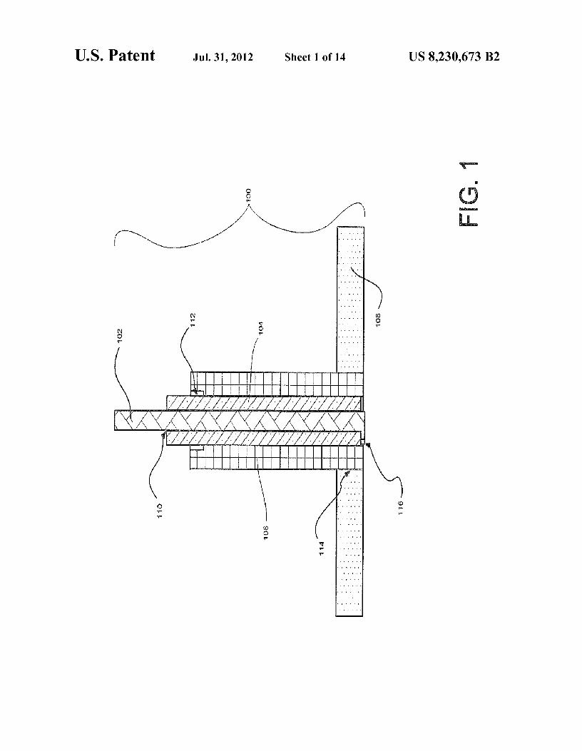
FIG.1 is a longitudinal cutaway view of a propellant injec-tor head according to the claimed invention.
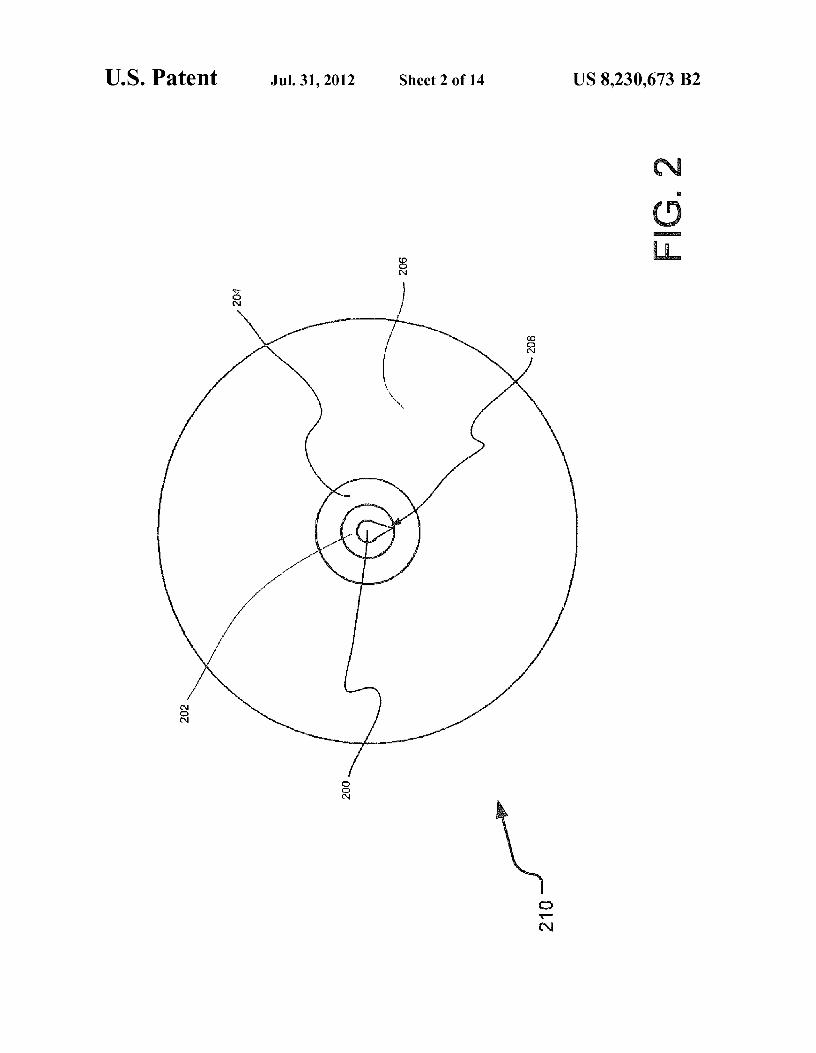
FIG. 2 is a frontal view of the propellant injector head as seen from inside a combustion chamber.
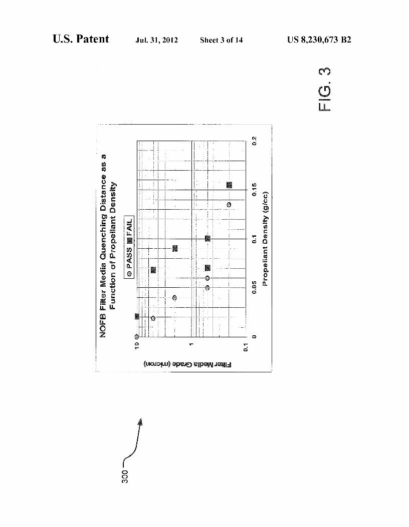
FIG. 3 illustrates the effective quenching distance for one exemplary combustible gas mixture of N 2O and fuel versus the mixed propellant density. In this case, quenching distance is estimated experimentally from the media grade particle size above which the filter will not pass.
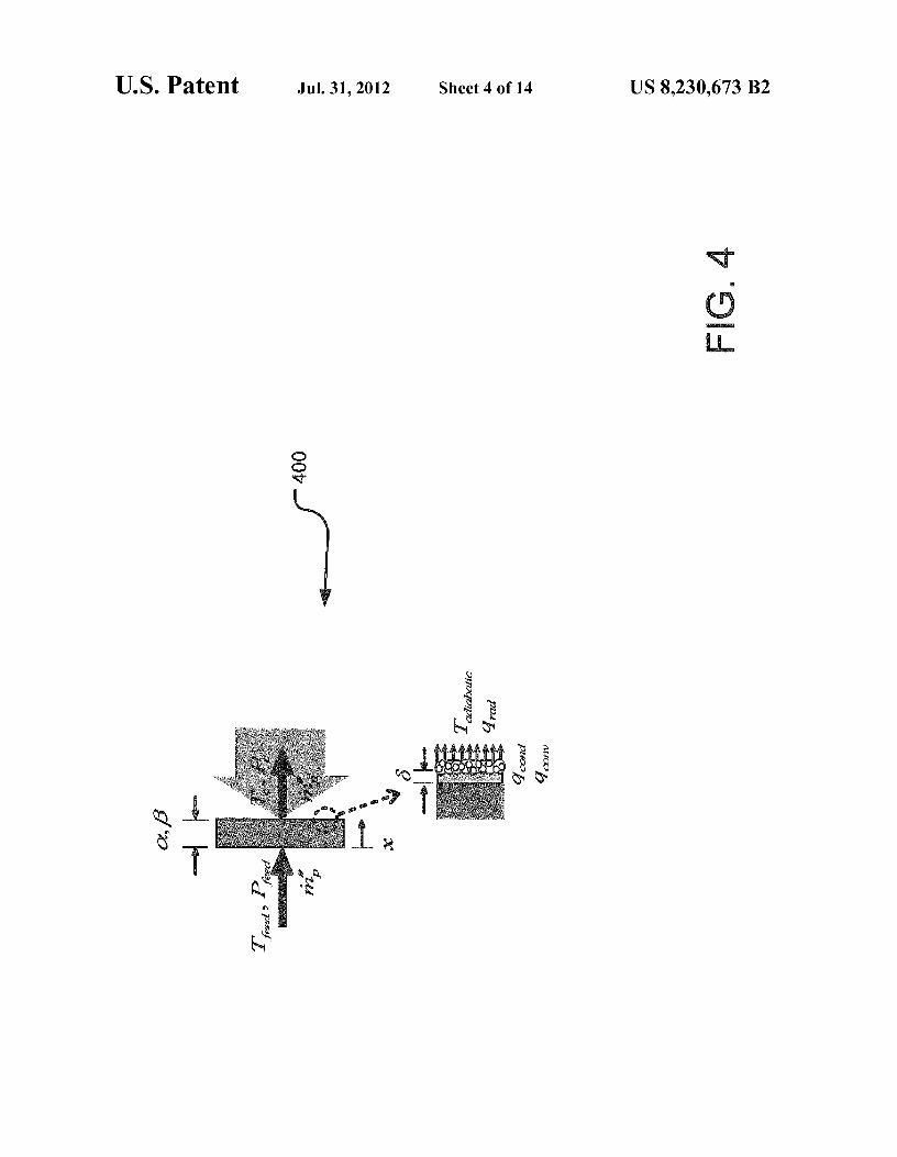
FIG. 4 is an illustration of geometry and parameters useful for understanding thermal distribution in a flame barrier and pressure drop across a flame barrier. Taaaba,, is the flame temperature; q—d, q d , q,o,,,, are the radiative, conductive, and convective heat fluxes respectively.
FIG. 5 is an illustration of internal flame barrier tempera-ture and pressure drop through an exemplary porous media flame barrier exposed to a chamber heating surface heat flux.
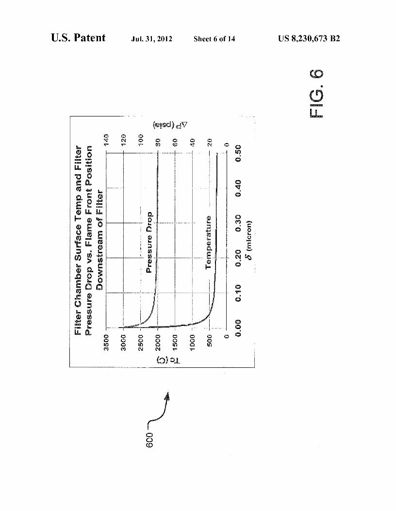
FIG. 6 is an illustration of analysis conducted to determine sensitivity of propellant pressure drop across the flame barrier and flame barrier combustion chamber face temperature as a function of flame-front position from the flame barrier face.
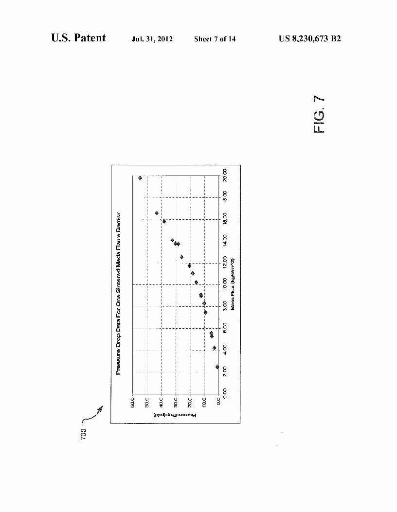
FIG. 7 is an illustration of experimental measurements of flame barrier pressure drop versus propellant mass flux.
FIG. 8 is a longitudinal cutaway view of the disclosed propellant injector head integrated into a prototype rocket thruster with a high temperature liner.
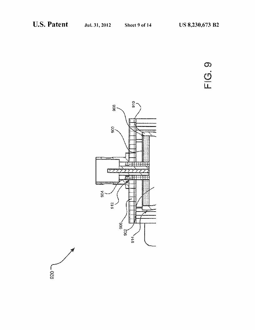
4 FIG. 9 is a longitudinal cutaway view of the disclosed
propellant injector head integrated into a sophisticated regen-eratively-cooled rocket thruster.
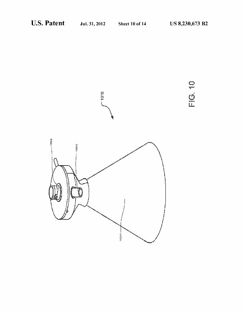
FIG. 10 is an isometric view of a regeneratively-cooled 5 rocket thruster that utilizes the disclosed propellant injector
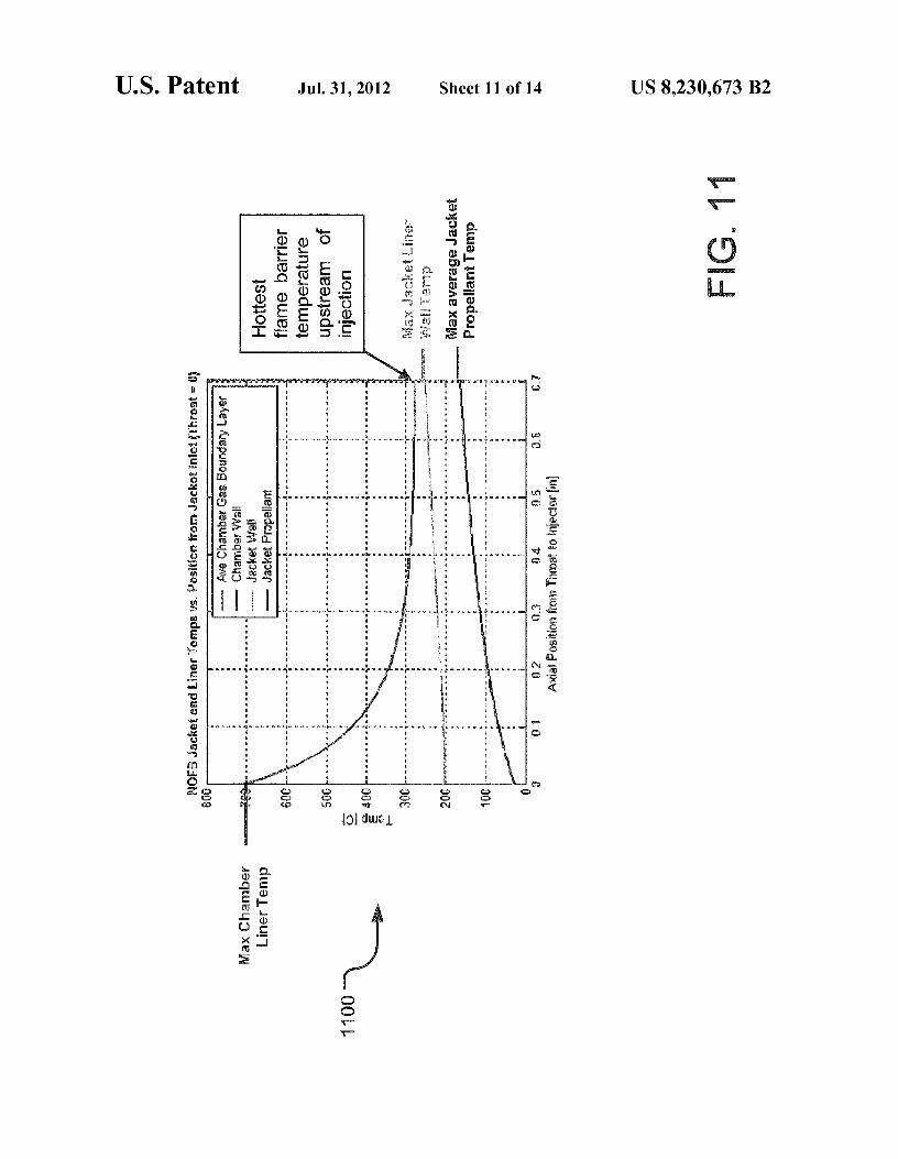
head. FIG. 11 is an illustration of exemplary thermal analysis
predicting the propellant preheat temperatures that a regen-eratively-cooled rocket thruster's propellant injector head
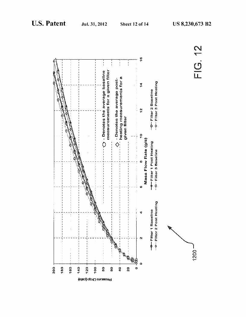
10 may encounter. FIG. 12 is an illustration of pressure drop versus propellant
mass flow rates before and after a filter has been subjected to oven heating at three different temperatures of 500° C., 750°
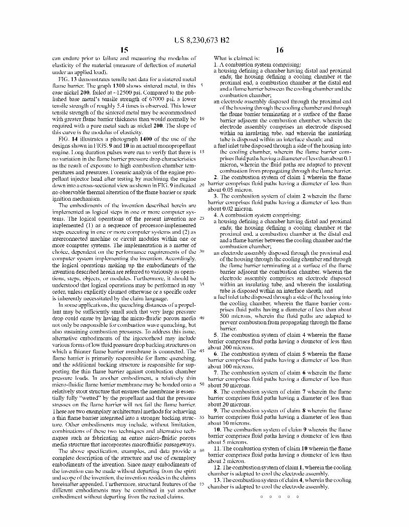
15 C., and 1000° C. FIG. 13 is experimental tensile testing data of one sintered
media flame barrier. FIG. 14 is an illustration of the propellant injector head
integrated into a monopropellant rocket engine application 20 undergoing testing and verification.
DETAILED DESCRIPTIONS
Implementations described and claimed herein address the 25 foregoing issues with a propellant injector head that incorpo-
rates specific design criteria that allows it to be used effec-tively with monopropellants or pre-mixed bipropellants. In addition, the propellant injector head provides a novel con-figuration that integrates a regenerative fluid-cooled spark
30 igniter into the chemical reactor to protect the spark igniter (i.e., the electrode) from degradation due to the high tempera-tures from combustion in the combustion chamber. The unique and novel propellant injector head design disclosed herein provides a substantial improvement in the art of rocket
35 propulsion allowing for use of a wide array of propellants, including those that combust at very high temperatures. Simi-lar to propellant injector head and propellants that have found application in other working fluid production and power gen-eration applications, the present technology may be utilized
40 in these types of applications as well. Before the present devices and methods are described, it is
to be understood that the invention is not limited to the par-ticular devices or methodologies described, as such, devices and methods may, of course, vary. It is also to be understood
45 that the terminology used herein is for the purpose of describ-ing particular embodiments only, and is not intended to limit the scope of the present invention; the scope should be limited only by the appended claims.
It should be noted that as used herein and in the appended 50 claims, the singular fauns "a," "an," and "the" include plural
referents unless the context clearly dictates otherwise. Thus, for example, reference to "a structure" refers to one structure or more than one structure, and reference to a method of manufacturing includes reference to equivalent steps and
55 methods known to those skilled in the art, and so forth. About" means plus or minus 10%, e.g., less than about 0.1 micron means less than 0.09 to 0.11 micron.
Unless defined otherwise, all technical and scientific terms used herein have the same meaning as commonly understood
6o by one of ordinary skill in the art to which this invention belongs. All publications mentioned are incorporated herein by reference for the purpose of describing and disclosing devices, formulations and methodologies that are described in the publication and that may be used in connection with the
65 claimed invention, including U.S. Ser. No. 12/268,266, filed Nov. 10, 2008, entitled "Nitrous Oxide Fuel Blend Monopro-pellant."
US 8,230,673 B2 5
Where a range of values is provided, it is understood that each intervening value, between the upper and lower limit of that range and any other stated or intervening value in that stated range is encompassed within the invention. The upper and lower limits of these smaller ranges may independently be included in the smaller ranges and are also encompassed within the invention, subject to any specifically excluded limit in the stated range. Where the stated range includes one or both of the limits, ranges excluding either or both of those included limits are also included in the invention.
In the following description, numerous specific details are set forth to provide a more thorough understanding of the present invention. However, it will be apparent to one of skill in the art that the present invention may be practiced without one or more of these specific details. In other instances, well-known features and procedures well known to those skilled in the art have not been described in order to avoid obscuring the invention. The art of chemical rocket propulsion makes use of controlled release of chemically reacted or un-reacted fluids to achieve thrust in a desired direction. The thrust acts to change a body's (i.e., the rocket's) linear or angular momen-tum. Similar to propellant injector heads and propellants that have found application in other working fluid production and power generation applications, the claimed invention may be utilized in many alternative types of applications as well, including gas generation for inflation systems and inflatable deployments, in systems used to convert thermal energy in hot exhaust gases to mechanical and electrical power, and in high energy storage media for projectiles, munitions, and explosives. Examples where the claimed technology could be applied specifically include earth-orbiting spacecraft and missile propulsion systems; launch vehicle upper stage pro-pulsion systems and booster stages; deep space probe propul-sion and power systems; deep space spacecraft ascent and earth return stages; precision-controlled spacecraft station-keeping propulsion systems; human-rated reaction control propulsion systems; spacecraft lander descent propulsion, power, and pneumatic systems for excavation, spacecraft pneumatic science sample acquisition and handling systems; micro-spacecraft high performance propulsion systems; mili-tary divert and kill interceptors; high altitude aircraft engines, aircraft backup power systems; remote low temperature power systems (e.g., arctic power generators); combustion powered terrestrial tools including high temperature welding and cutting torches as well as reloadable charges for drive mechanisms (e.g., nail guns, anchor bolt guns), and the like. Moreover, there are many derivative applications related to using combustion stored energy and the delivery systems therefor.
In the case of many terrestrial combustion power applica-tions (e.g., gas and diesel engines), the oxidizer is commonly atmospheric air which consists of oxygen that is highly reac-tive in the combustion reaction and relatively inert gases such as nitrogen. Bipropellants are either injected as separate fluids into a chemical reaction chamber or mixed immediately prior to injection (e.g., in carbureated or fuel-injected piston com-bustion engines).
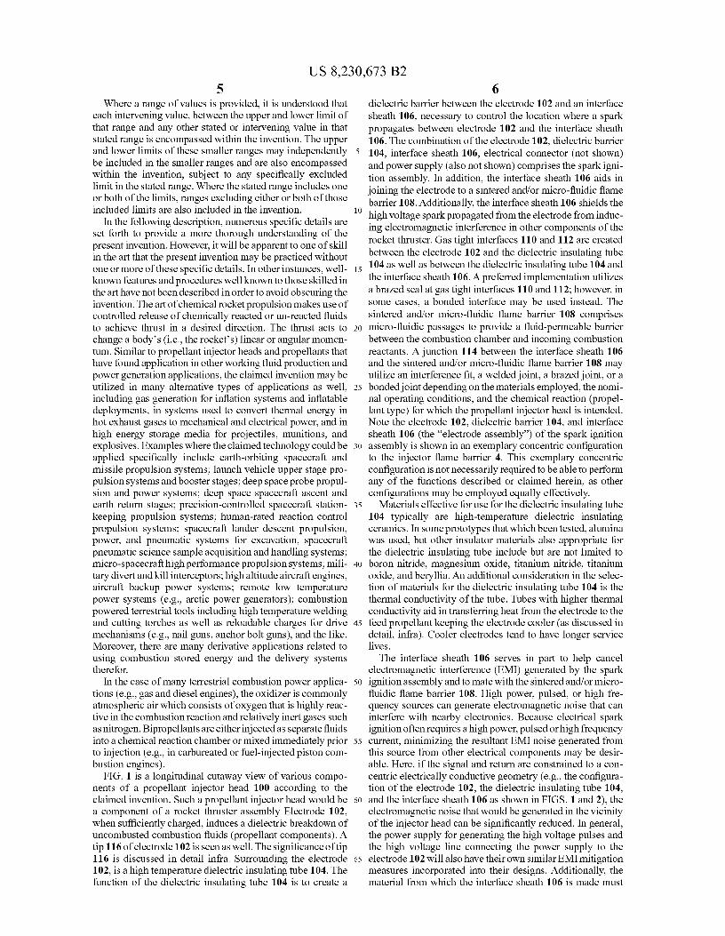
FIG. 1 is a longitudinal cutaway view of various compo-nents of a propellant injector head 100 according to the claimed invention. Such a propellant injector head would be a component of a rocket thruster assembly Electrode 102, when sufficiently charged, induces a dielectric breakdown of uncombusted combustion fluids (propellant components). A tip 116 of electrode 102 is seen as well. The significance of tip 116 is discussed in detail infra. Surrounding the electrode 102, is a high temperature dielectric insulating tube 104. The function of the dielectric insulating tube 104 is to create a
6 dielectric barrier between the electrode 102 and an interface sheath 106, necessary to control the location where a spark propagates between electrode 102 and the interface sheath 106. The combination of the electrode 102, dielectric barrier
5 104, interface sheath 106, electrical connector (not shown) and power supply (also not shown) comprises the spark igni-tion assembly. In addition, the interface sheath 106 aids in joining the electrode to a sintered and/or micro-fluidic flame barrier 108. Additionally, the interface sheath 106 shields the
to high voltage spark propagated from the electrode from induc-ing electromagnetic interference in other components of the rocket thruster. Gas tight interfaces 110 and 112 are created between the electrode 102 and the dielectric insulating tube
15 104 as well as between the dielectric insulating tube 104 and the interface sheath 106. A preferred implementation utilizes a brazed seal at gas tight interfaces 110 and 112; however, in some cases, a bonded interface may be used instead. The sintered and/or micro-fluidic flame barrier 108 comprises
20 micro-fluidic passages to provide a fluid-permeable barrier between the combustion chamber and incoming combustion reactants. A junction 114 between the interface sheath 106 and the sintered and/or micro-fluidic flame barrier 108 may utilize an interference fit, a welded joint, a brazed joint, or a
25 bonded joint depending on the materials employed, the nomi-nal operating conditions, and the chemical reaction (propel-lant type) for which the propellant injector head is intended. Note the electrode 102, dielectric barrier 104, and interface sheath 106 (the "electrode assembly") of the spark ignition
so assembly is shown in an exemplary concentric configuration to the injector flame barrier 4. This exemplary concentric configuration is not necessarily required to be able to perform any of the functions described or claimed herein, as other configurations may be employed equally effectively.
35 Materials effective for use for the dielectric insulating tube 104 typically are high-temperature dielectric insulating ceramics. In some prototypes that which been tested, alumina was used, but other insulator materials also appropriate for the dielectric insulating tube include but are not limited to
4o boron nitride, magnesium oxide, titanium nitride, titanium oxide, and beryllia. An additional consideration in the selec-tion of materials for the dielectric insulating tube 104 is the thermal conductivity of the tube. Tubes with higher thermal conductivity aid in transferring heat from the electrode to the
45 feed propellant keeping the electrode cooler (as discussed in detail, infra). Cooler electrodes tend to have longer service lives.
The interface sheath 106 serves in part to help cancel electromagnetic interference (EMI) generated by the spark
50 ignition assembly and to mate with the sintered and/or micro- fluidic flame barrier 108. High power, pulsed, or high fre- quency sources can generate electromagnetic noise that can interfere with nearby electronics. Because electrical spark ignition often requires a high power, pulsed or high frequency
55 current, minimizing the resultant EMI noise generated from this source from other electrical components may be desir- able. Here, if the signal and return are constrained to a con- centric electrically conductive geometry (e.g., the configura- tion of the electrode 102, the dielectric insulating tube 104,
6o and the interface sheath 106 as shown in FIGS. 1 and 2), the electromagnetic noise that would be generated in the vicinity of the injector head can be significantly reduced. In general, the power supply for generating the high voltage pulses and the high voltage line connecting the power supply to the
65 electrode 102 will also have their own similar EMI mitigation measures incorporated into their designs. Additionally, the material from which the interface sheath 106 is made must
US 8,230,673 B2 7
typically have a coefficient of thermal expansion (CTE) that is similar to the material of the sintered and/or micro-fluidic flame barrier 108.
Stresses at joint 114 induced by heating conditions com-monly encountered in combustion applications may cause joint failure. Alternatively or in addition, if an interference fit is made with a sintered or micro-fluidic flame barrier com-prising a material with a dissimilar CTE, a small gap may form at joint 114. A joint failure and/or release at 114 may lead to flame propagation around the sintered and/or micro-fluidic flame barrier causing the propellant injector head to fail in its intended purpose of preventing flame back-propa-gation back up the propellant feed system line to the propel-lant storage reservoir. This type of failure is commonly known as flashback and is described in more detail below. For this reason, the material used for the interface sheath 106 preferably either is the same as the sintered and/or micro-fluidic flame barrier 108, or, alternatively, the CTEs of the different materials used for these two components is closely matched based on the anticipated temperatures that the com-ponents will have to endure. For propellant injector heads of the claimed invention, a nickel 200 interface sheath 106 was used. Other materials that may be employed for the interface sheath 106 and the sintered and/or micro-fluidic flame barrier 108 may include, but are not limited to, various stainless steel alloys, pure nickel, various nickel alloys, niobium, rhenium, molybdenum, tungsten, tantalum, and alloys thereof. For the particular assembly shown, 5 micron media grade nickel 200 was utilized. Other propellant injector heads used with dif-ferent propellants in different applications can utilize differ-ent materials. In some implementations, the flash barrier comprises fluidpaths having a diameter of less than about 250 microns, or less than about 150 micron, or less than about 100 microns, or less than about 70 microns, or less than about 50 microns, or less than about 20 microns or less than about 10 microns, or less than about 7 microns, or less than about 5 microns, or less than about 1 micron, or less than about 0.5 micron, or less than about 0.2 micron, or less than about 0.1 micron, or less than about 0.05 micron. In yet other aspects, such as those associated with atmospheric and low pressure applications, the flame barrier comprises fluid paths having a diameter of less than about 20 mm, or less than about 15 mm, or less than about 10 mm, or less than about 5 mm, or less than about 2.5 mm, or less than about 1 mm, or less than 0.5 mm, or less than about 0.25 mm. The preferred pore size is prima-rily dependent on the energy density of the propellant which is a function of both the specific energy (energy per unit mass) of the propellant and the fluid density (mass per unit volume) of the propellant which can vary from high density liquids to very low density gases.
FIG. 2 is a frontal view of the propellant injector head as seen from the combustion chamber, showing sparker geom-etry and exemplary spark assembly placement. The electrode tip geometry and the material selection of the electrode 200 are important features. A sharp tip 208 is created on the electrode 200 on the combustion chamber side of the elec-trode 200, which serves to concentrate an electromagnetic field at tip 208 (tip 208 may also be seen in a different perspective in FIG. 1 at 116). Concentrated electromagnetic fields allow for generation of a voltage breakdown necessary for generating a spark. An arcing spark, if sufficiently ener-getic, will ignite a combustible fluid. The gap of the arc is commonly set to allow both minimum voltages to be applied in order to generate a spark and provide sufficient spark gap energy to initiate the combustion process. Every gas mixture has a different voltage breakdown curve (breakdown voltage versus variable, pd=mixture_pres sure* gap —di stance) that is
8 dependent on combustible gas pressure, gap distance, and gap geometry. Therefore, gap distances and applied voltages to the electrode may vary depending on the combustible gas mixture and electrode tip geometry. In general, a wide array
5 of electrode tip geometries (e.g., single point, double point, triple point, quadruple point, star pattern, split electrode, etc.), in addition to the exemplary tip geometry shown in FIG. 2, will produce electric fields necessary for generating a spark in a combustible mixture that is capable of initiating an exo-
10 thermic combustion process. Also seen in FIG. 2 are the dielectric insulating tube 202, the interface sheath 204, and the sintered and/or micro-fluidic flame barrier 206.
The sintered and/or micro-fluidic flame barrier (seen in 15 FIG. 1 at 108) is designed to prevent flames and/or initial
combustion (deflagration and/or detonation) waves from reaching the uncombusted propellant in a propellant feed system. Typically during ignition, combustion waves are gen-erated that must be prevented from interacting with the
20 uncombusted propellant in the propellant feed system which could cause a flashback. For relatively steady-state flow applications (i.e., rocket engine), after ignition, a relatively steady-state flame-front will form and reside downstream of the flame barrier (FIG. 4). In other processes (e.g., a piston
25 engine) the flame-front may momentarily interact with the flame barrier at each combustion cycle in which case the flame barrier also acts as a thermal reservoir to absorb com-bustion thermal energy during this short duration interaction and dissipates the thermal energy into the next cycle's
30 uncombusted inlet propellant during injection. A very important parameter for designing the flame barrier
108 is the quenching distance of a monopropellant. This is the smallest flowpath dimension through which a flashback flame can propagate. Smaller flowpath sizes will quench a flame
35 and, in general, prevent flashback. However, secondary igni- tion by heat transfer through a solid that is in contact with the unreacted monopropellant must also be ultimately consid- ered (flame barrier thermal analysis is described below). In general, the higher the energy density of the propellant and/or
40 combustible mixture, the smaller the quenching distance. In actual practice this dimension (here, approximately the diam- eter of a micro-fluidic flowpath) is affected by additional parameters such as tortuosity (curviness of flow path) and to a lesser extent the temperature of the solid containing the
45 flowpath. The propellant energy density is described by Eq. 1:
The Propellant _Energy _Density —Propellant _ Fluid_ DensityxPropellant_ Specific _Energy (1)
Some propellants have flame quenching distances on the 50 order of microns and for very high fluid density (mass per unit
volume), high propellant specific energy (energy per unit mass) propellants, these quenching distances can even be smaller. Quenching distances can be much larger (>mm) for low fluid density (i.e. low pressure combustible gases) and
55 lower specific energy (e.g. hydrazine, hydrogen peroxide) propellants. FIG. 3 illustrates the highly non-linear but mono-tonically decreasing quenching distance with increasing pro-pellant density of an exemplary combustible mixture. This figure demonstrates the wide range of quenching distances
60 over a relatively narrow range of propellant energy density (in this case dominated by propellant fluid density).
The flame speed, or burn speed, is the speed at which the propellant is consumed. In general, the flamespeed of the burningpropellant(s) mustbe greater than the flow velocity of
65 the combustion gases inside a combustion chamber. If it is not, the flame will be "blown-out" of the combustion cham- ber, and the combustion reaction will not be sustained. How-

US 8,230,673 B2 9
ever, flamespeeds (not to be confused with combustion wave or detonation wave velocity) of many combustible mixtures can be quite low (–I O's cm/s to 10 m/s). As a result, in order to adequately slow down the propellant flow through the micro-fluidic porous media injectorhead into the combustion chamber to prevent "flame blow-out", a very large injector-head may be required. Alternatively, in the design of the injectorhead, turbulent flow conditions for the injected pro-pellant flow can be ensured over the operational mass flow rates that the injectorhead is expected to encounter. This injected turbulent flow has the effect of significantly aug-menting the local flamespeed. As a result, in the region of turbulent flow downstream of the injectorhead, "Flame-hold-ing" is feasible (see FIG. 4 region immediately downstream of 6). In many cases, the improvement in flamespeed can be a –10x enhancement relative to the normal laminar flamespeed. The surface area of an injector designed to oper-ate with turbulent flow can be scaled back in size by approxi-mately the same gain in flame speed. As a result, injector-heads designed to operate under turbulent injected flow conditions can be expected to be significantly smaller in surface area than injectors designed to operate under very low speed laminar flow conditions. Operating under turbulent flow conditions (i.e. high mass flux) does cause increased pressure drop through the injectorhead. This increased pres-sure drop through a micro-fluidic porous media element can be mitigated, however, by the use of the advanced micro-fluidic porous media designs described in the paragraphs below. Turbulence is a complex fluid phenomenon by itself [Davies, J. T., Turbulence Phenomena. Academic Press. New York, 1972] which is augmented with a chemically reacting flow. Nevertheless, recent experimental research in combus-tion sciences has validated empirical models for estimating turbulent flamespeeds under a wide range of conditions [Li-patnikov, A. N., and Chomiak, 7., Turbulent flame speed and thickness: phenomenology, evaluation, and application in multi-dimensional simulations. Progress in Energy and Com-bustion Science 28, pp 1-74 (2002).]. One such exemplary model derived from the Zimont model for turbulent flame speed [Lipatnikov, A. N., and Chomiak, 7., Turbulent flame speed and thickness: phenomenology, evaluation, and appli-cation in multi-dimensional simulations. Progress in Energy and Combustion Science 28, pp 1-74 (2002).] and models for turbulence generated in pipe flow conditions is shown in Eq. 2.
U,-0.213 pu 0s0p,-0.28D-1.281h0.78 Pr 0.25SL00 s (2)
where U, is the estimated turbulent flame speed; P,-0-50 is the unburned propellant's fluid density, µu 0.211 is the unburned propellant's dynamic viscosity, D` 211 is the pipe diameter, m0 78 is the mass flow rate of propellant, Pr u0.25 is the Prandtl number of the unburned propellant, and Si,o .5 is the laminar flamespeed of the propellant. This equation allows one to design injectorheads that have nominally higher turbulent flamespeeds than propellant velocities going into a combus-tion chamber. In practice, given the complexity of turbulent flows, a particular design should be experimentally validated for its flameholding capability in addition to all of the other important performance metrics that would be desired for an injectorhead in a particular application (e.g. minimal pressure drop through the injectorhead, reasonable injectorhead tem-peratures that don't decompose the propellant prior to entry into the combustion chamber and/or fail the injectorhead materials, ability to filter out pressure instabilities, etc.).
FIG. 3 illustrates exemplary experimental data of sintered metal pore sizes sufficient for quenching a nitrous oxide and
10 fuel bipropellant that has been mixed at propellant densities associated with –50-500 psia combustible gas mixtures. Graph 300 shows that the quenching distance is a function of the propellant density in the pores, which in turn is dependent
5 on the liquid/gas being used and the pressure and temperature distribution inside the micro-fluidic porous media flame bar-rier element. As pore sizes decrease in a flame barrier design, the pressure drop across a micro-fluidic porous media ele-
lo ment will, in general, increase such that arbitrarily small pore sizes are not necessarily feasible (pressure drop analysis is described in more detail below). In the experiment from which this data is derived, a I footx' /4 in stainless steel line was loaded with premixed propellant with the sintered metal
15 flame barrier on one end. The line was intentionally deto-nated. A combustible solid on the opposite side of the flame barrier was monitored to determine if a back-propagation through the flame barrier had occurred.
Drawing 400 in FIG. 4 illustrates flame barrier, flame- 2o
front, and propellant fluid parameters and geometry useful for understanding how quasi-steady-state combustion thermal interactions effect propellant pressure drop and internal flame barrier temperatures. a and R are viscosity and inertia flow
25 coefficients, respectively, that are correlated with the flame barrier filter pore size and micro-fluidic fluid geometry and tortuosity.
During operation, the sintered media and/or micro-fluidic media flame barrier 108 (also seen at 804 of FIG. 8 and 900 of
3o FIG. 9) cause(s) a fluid pressure drop. This pressure drop needs to be considered in the design of an upstream pressurant system. In general, the pressure drop mechanism in the pro-pellant injector head also helps to filter out pressure oscilla-tions associated with combustion instabilities in a combus-
35 tion and/or chemical reaction chamber (820, 902) that could ultimately lead to catastrophic chamber failure. The propel-lant injector head is designed to accommodate a specific flow rate of propellant, differential pressure, and combustion
40 chamber operating pressure. In general, the flow rate of pro-pellant and operating pressure are commonly specified for a particular application. For example, by combining the mass flow of propellant and desired combustion chamber operating pressure with knowledge of the combustion chemistry and
45 rocket nozzle design, it is possible to determine the output thrust a rocket engine will produce. In such a scenario, for a desired rocket engine thrust and nominal operating chamber pressure, the sintered media and/or micro-fluidic flame bar-rier (108, 804, 900) would be designed to provide a desired
5o differential pressure drop for the prescribed mass flow rate of propellant. In combination with an upstream feed system pressurant design, this differential pressure drop would ensure that the desired combustion chamber pressure is achieved and/or maintained during operation. To adjust the
55 differential pressure drop, the flame barrier thickness and cross-sectional area to the mass flow can be varied.
The pressure drop gradient (pressure drop per unit length that fluid traverses through injector medium) across the inj ec-
60 tor/flame barrier is related to the rate of propellant mass flux
that passes through the flame barrier (M— "P is the propellant mass flow rate per unit surface area), the fluid density of fluid traveling through the flame barrier (p), the propellant's dynamic viscosity (µ), and typically flame barrier fluid-inter-
65 action parameters, a and R. An exemplary mathematical expression that relates all of these injectorhead and propellant fluid parameters is:
US 8,230,673 B2 11
12
0P=- P + f a
In practice, particularly for two-phase (combination liquid and gas) flows, this relationship can be more complicated such that actual experimental measurements of pressure drop through the flame barrier versus mass flow rate under similar operating conditions as would be encountered in real appli-cation is a better technique for ultimately deriving flame barrier specifications. It is worth noting that since pressure drop is dependent on fluid density and temperature, and dynamic viscosity is dependent on temperature, combustion processes will, in general, influence the pressure drop through the flame barrier.
Graph 500 in FIG. 5 illustrates an exemplary analysis (based on the pressure drop theory of diffusive flow as described above) of propellant temperature and pressure as propellant traverses through a porous media flame barrier with a radiative and convective heat flux on the combustion chamber face of the flame barrier.
FIG. 6 illustrates the sensitivity of propellant fluid pressure drop across the flame barrier and surface temperature (cham-ber-side) of the flame barrier as a function of the location of the flame-front. As shown on graph 600, an exemplary pro-pellant with an adiabatic flame temperature (T,,,,,,, is the maximum combustion temperature of a combusted propel-lant) of 3177° C. is analyzed using heat transport and ther-mophysical properties of the uncombusted and combusted exemplary propellant.
FIG. 7 illustrates an example measurement of experimental pressure drop across a propellant injector head flame barrier. As a preliminary step in the injector head design process, it is often advantageous to define the flow characteristics of a flame barrier. The experiment that generated the graph 700 shown in FIG. 7 utilized a number of pressure transducers (electrical sensors used to measure fluid pressure) and mass flow measurements to determine both propellant mass flow rate and the pressure drop across a flame barrier. Mass flow rate is converted into a normalized mass flux by dividing the mass flow rate by the cross-sectional area of the exposed flame barrier. The resultant curve generated from this data can be used to size the cross-sectional area of a flame barrier for a given mass flow rate and desired differential pressure drop across the flame barrier, or alternatively can be used to esti-mate pressure drop for a given flame-barrier design for example.
Typical manufacturing methods for producing small fluid paths in a machined device (e.g., drilling, punching, etc.) for the most part are incapable of or are uneconomical for pro-ducing a viable propellant injector head to address the small required quenching distances. However, porous components, such as may be created by sintering pre-sorted media, can effectively create flow paths as small as 0.1 micron and smaller. In one implementation, sintered metal is produced by means of a powdered metallurgy process. The process involves mixing metal powder of a specific grain size with lubricants or additional alloys. After the mixture is complete, the mixed powder is compressed (e.g., an exemplary range of pressures is between about 30,000 lbs. and about 60,000 lbs or more per square inch) by machine to form a "compact", where typical compacting pressures are between 25 and 50 tons per square inch. Each compact is then "sintered" or heated in a furnace (e.g., to a temperature lower than the melting point of the base metal) for an extended period of
time to be bonded metallurgically. In one implementation, the sintered metal contains micro-fluidic passages that are rela-tively consistent in composition, providing flow paths as small as 0.1 micron or less.
5 One propellant injector head prototype tested utilized a sintered metal filter as the flame barrier between the combus-tion chamber and the propellant inlet. However, other porous materials having micro-fluidic passages may be used in alter-native designs including sintered ceramic filters and laminate
io structures. The propellant injector head design shown in FIG. 1 and described herein facilitates two major functions, namely, creation of a flame proof barrier and integration of a propellant spark-ignition mechanism. In the case ofbipropel-lants or propellants with multiple constituents, however, the
15 diffusive barrier can also provide a means for mixing propel-lant constituents very thoroughly prior to injection into a combustion or chemical reaction chamber by utilizing a highly tortuous network of micro-fluidic passages.
In general, the combustion process generates very high 20 temperatures. The geometries shown in drawing 830 of FIG.
8 and drawing 920 of FIG. 9 help mitigate electrode heating by utilizing the incoming combustible propellant as a regen-erative (i.e., where thermal energy is not lost) coolant. Nev-ertheless, radiative, conductive, and convective heating of the
25 electrode in a high temperature combustion chamber com-monly results in temperatures that are higher than many con-ventional metals' operating limits. Furthermore, electrode life is generally longer with higher temperature electrode materials when exposed to high temperature chemical reac-
30 tion and combustion processes. Thus, in some implementa-tions, higher temperature electrode materials are used such as but not limited to refractory metals including tungsten, molybdenum, niobium, tantalum, rhenium, and alloys thereof. Niobium has been used effectively in numerous pro-
35 totype propellant injector headprototypes and was used inthe prototypes tested such as shown in FIG. 11. Niobium pos-sesses a number of favorable attributes including a close CTE match with exemplary alumina electrical insulators which helps prevent tensile stresses (common failure mechanism in
40 ceramics) from being generated in the interface sheath (seen at 104 in FIG. 1) under high temperature thermal loading, resistance to thermal shock, high ductility and high strength. The ductility is particularly attractive for fabrication pro-cesses that utilize cold working as a fundamental fabrication
45 procedure. In one implementation, manufacturing comprised three primary steps. First, the end of a Niobium rod was flattened by mechanically deforming the tip. Second, the tip was bent to achieve a 90° bend. Finally, the excess material was removed to create a part dimensionally and geometrically
50 similar to that shown in FIGS.1 and 2. Alternative methods of manufacturing include machining (traditional or (electrical discharge machining), mechanical forming, sinter pressing, molding, casting, punching, welding (by electrode, e-beam or laser), or a combination thereof.
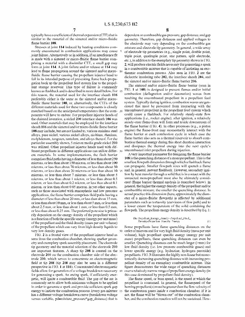
55 FIG. 8 is a longitudinal cutaway view of a ceramic-lined rocket thruster to demonstrate an exemplary configuration of the propellant injector head as a component of the rocket thruster. In this implementation, combustor reactants enter through a propellant inlet tube 810, enter a cooling chamber
60 826, travel through the sintered and/or micro-fluidic flame barrier 804, ignite within the combustion chamber 820, travel through an ablative liner 802, and exit through the thrust throat constriction 822. Between the propellant inlet tube 810 and the sintered and/or micro-fluidic flame barrier 804, the
65 un-reacted propellant flows into a cooling chamber 826 that provides cooling to the propellant injector head (the combi-nation of components comprising electrode 816, dielectric

US 8,230,673 B2 13
14 insulating tube 814, interface sheath 812, and sintered and/or
1002, and exit through an exit cone 1004. Other possible
micro-fluidic flame barrier 804 as described in the detailed
configurations for the combustion chamber include, but are description of FIGS.1 and 2). Recall that a seal is created 824
not limited to, refractory metal combustion chambers, regen-
at the junction of the sintered and/or micro-fluidic flame eratively cooled chambers, ceramic chambers, or any combi- barrier 804 with the thruster case 800. Seal 824 can be created 5 nation thereof. by welding, brazing, bonding, or mechanical interference. An
For purposes of helping define the temperature extremes
additional seal 818 is created at the junction of the thruster that a flame barrier and its bonded joints must endure, graph body cap 808 to the interface sheath 812. Depending on
1100 of FIG. 11 illustrates exemplary thermal analysis of the
application and material choice, seal 818 can be made by a regeneratively cooled engine (FIGS. 9 and 10). In this case, braze j oint, weld j oint, mechanical interference fit, or bonded io the temperature of the uncombusted propellant is analyzed joint. However, as discussed previously, the use of proper
from the injection into a combustion chamber cooling jacket
seals is imperative in proper propellant injector head function to the point where the flame barrier is attached to the com- in many implementations. Improper integration of the pro- bustion liner wall 908. An engine with a high temperature pellant injector head assembly into a rocket thruster (e.g., liner (FIG. 8) has a flame barrier temperature that has been improper fit or faulty seals) can pose a substantial safety risk. 15 previously analyzed in FIG. 5. The maximum filter tempera- Prototypes built and used tested successfully have utilized a ture of the regeneratively cooled engine is approximately the combination press/brazed flame barrier outer seal 824, and a sum of the max jacket preheated propellant temperature brazed interface shield/thruster body cap seal 818. Note also shown in FIG. 11 and the maximum temperature modeled in in this cross sectional view are the dielectric insulating tube
FIG. 5. In the exemplary analysis for the regeneratively
814 and the electrode 816. A BNC (Bayonet Neil-Concel- 20 cooled engine concept, the maximum flame barrier tempera- man)-type electrical connector 806 is an exemplary common ture would, therefore, be <600' C. for a flame-front that electrical connector that may be used to interface a high
resides >1 micron from the flame barrier chamber surface.
voltage line to the electrode 816 and facilitate current delivery
Propellant injector head design must consider many fac- from and current return to a high voltage power supply. tors, such as, but not limited to, flame quenching distances,
Another feature of the propellant injector head of the 25 pressure drop variation due to propellant heating in the flame claimed invention is the integration of an actively cooled
barrier, mechanical loading on a hot porous structure (e.g.,
spark ignition mechanism. Some of the particular monopro- pressure loads on the heated injector face), loss of mechanical pellants for which the integrated propellant injector head was strength due to heating, possible sintering of micro-fluidic created combust at an extremely hot temperature (around
passageways and pores where the propellant injection speeds
3200° C.). Therefore, placing conventional sparking mecha- 30 into the chamber are low enough to allow the flamefront to nisms (i.e., electrodes) in the combustion chamber would
stabilize too close to the flame barrier surface (see FIG. 4 and
result in melting of nearly any electrode material. However, FIG. 6). because the electrode and surrounding dielectric insulating
Furthermore, propellant injector head design must also
tube and interface sheath are cooled (e.g., by incoming fluid
factor in the material selection and fabrication steps necessary delivered by the propellant inlet tube 810 and cooling cham- 35 for providing high temperature reliable bonds at the locations ber 826 of FIG. 8), very hot exothermic combustion reactions
described infra. To verify that high temperature bonding pro-
may be sustained without degrading the sparking mechanism. cesses would not significantly alter or cause a sintered and/or FIG. 9 is a longitudinal cutaway view of a regenerative micro-fluidic flame barrier to fail, a series of experiments
cooled rocket thruster truncated slightly below the combus- were performed on sintered metal filters with various pore tion chamber to demonstrate additional features. In this 40 sizes. implementation, the combustion reactants encounter the pro- FIG. 12 illustrates graph 1200 of experimental data of pellant injector head via an annular regenerative cooling path- sintered metal filters exposed to oven heating to temperatures way 914 which cools the combustion chamber, flame-barrier that may be encountered in actual operation or during high joint 908, and the electrode assembly portion of the spark
temperature bonding processes. In this experiment a sintered
ignition assembly. The combustion reactants then pass 45 metal filter's pressure drop versus mass flow rate was mea- through the sintered and/or micro-fluidic flame barrier 900, sured before and after a filter had been heated to determine if and are ignited within the combustion chamber 902. The there was any significant changes in the micro-fluidic struc- propellant injector head assembly is configured as outlined in ture based on global pressure drop estimate properties. Oven the detailed descriptions of FIG. 1 and FIG. 2. The sintered
heating temperatures cases of 500° C., 750° C. and 1000° C.
and/or micro-fluidic flame barrier 900 is sealed 908 directly 50 were tested. As can be seen, very little permanent changes to the combustion chamber walls 910. Depending on appli- occurred to the filter. Furthermore, these temperatures are cation and material choice, seal 908 can be made by braze significantly higher than the internal filter temperatures esti- joint, weld joint, mechanical interference fit, or bonded j oint. mated previously using the theoretical analysis (described An additional seal 912 is created at the junction of the inter- above) for the specific case where the flame-front can be face sheath 904 and the thruster body cap 906. Depending on 55 controlled to be >1 micron from the flame-barrier surface. the application of the propellant injector head and material
In some combustion or chemical reaction chamber sce-
choice, seal 912 can be made by braze joint, weld joint, narios, chamber pressures can potentially be quite high (e.g., mechanical interference fit, or bonded joint. One implemen- 100's to >1000 psia). Furthermore, high mass flow rates and tation used in testing prototypes of fuel infector heads of the pulsed combustor operation can cause large pressure gradi- claimed invention successfully employed a mechanical inter- 60 ents to exist across an injector head. If the injector head does ference for the outer flame barrier seal 908, and a brazed
not have sufficient mechanical strength, the porous structure
interference sheath/thruster body seal 912. may open under tensile loading and a subsequent failure FIG. 10 illustrates a drawing 1006 of an isometric view of
resulting in a flashback can occur. For this reason it is impor-
a regenerative cooled rocket thruster. Combustion reactants tant to ensure that the worst-case pressure loading in opera- enter through the propellant inlet tube 1000, pass through the 65 tion can not cause an injector head mechanical failure. A propellant injector head as shown in FIG. 1 and FIG. 8, are
flame barrier's resistance to pressure loading can be esti-
ignited via a spark pulse delivered to the BNC connector mated by measuring the tensile stresses that filter materials
US 8,230,673 B2 15
can endure prior to failure and measuring the modulus of elasticity of the material (measure of deflection of material under an applied load).
FIG. 13 demonstrates tensile test data for a sintered metal flame barrier. The graph 1300 shows sintered metal, in this case nickel 200, failed at —12500 psi. Compared to the pub-lished base metal's tensile strength of 67000 psi, a lower tensile strength of roughly 5.4 times is observed. This lower tensile strength of the sintered metal may be accommodated with greater flame barrier thickness than would normally be required with a pure metal such as nickel 200. The slope of this curve is the modulus of elasticity.
FIG. 14 illustrates a photograph 1400 of the use of the designs shown in FIGS. 9 and 10 in an actual monopropellant engine. Long duration pulses were run to verify that there is no variation in the flame barrier pressure drop characteristics as the result of exposure to high combustion chamber tem-peratures and pressures. Forensic analysis of the engine pro-pellant injector head after testing by machining the engine down into a cross-sectional view as shown in FIG. 9 indicated no observable thermal alteration of the flame barrier or spark ignition mechanism.
The embodiments of the invention described herein are implemented as logical steps in one or more computer sys-tems. The logical operations of the present invention are implemented (1) as a sequence of processor-implemented steps executing in one or more computer systems and (2) as interconnected machine or circuit modules within one or more computer systems. The implementation is a matter of choice, dependent on the performance requirements of the computer system implementing the invention. Accordingly, the logical operations making up the embodiments of the invention described herein are referred to variously as opera-tions, steps, objects, or modules. Furthermore, it should be understood that logical operations may be performed in any order, unless explicitly claimed otherwise or a specific order is inherently necessitated by the claim language.
In some applications, the quenching distances of a propel-lant may be sufficiently small such that very large pressure drop could ensue by having the micro-fluidic porous media not only be responsible for combustion wave quenching, but also sustaining combustion pressures. To address this issue, alternative embodiments of the injectorhead may include various forms of low fluid pressure drop backing structures on which a thinner flame barrier membrane is connected. The flame barrier is primarily responsible for flame quenching, and the additional backing structure is responsible for sup-porting the thin flame barrier against combustion chamber pressure loads. In another embodiment, a relatively thin micro-fluidic flame barrier membrane may be bonded onto a relatively stout structure that ensures the membrane is essen-tially fully "wetted" by the propellant and that the pressure stresses on the flame barrier will not fail the flame barrier. These are two exemplary architectural methods for achieving a thin flame barrier integrated into a stronger backing struc-ture. Other embodiments may include, without limitation, combinations of these two techniques and alternative tech-niques such as fabricating an entire micro-fluidic porous media structure that incorporates macrofluidic passageways.
The above specification, examples, and data provide a complete description of the structure and use of exemplary embodiments of the invention. Since many embodiments of the invention can be made without departing from the spirit and scope of the invention, the invention resides in the claims hereinafter appended. Furthermore, structural features of the different embodiments may be combined in yet another embodiment without departing from the recited claims.
16 What is claimed is: 1. A combustion system comprising: a housing defining a chamber having distal and proximal
ends; the housing defining a cooling chamber at the 5 proximal end, a combustion chamber at the distal end
and a flame barrier between the cooling chamber and the combustion chamber;
an electrode assembly disposed through the proximal end of the housing through the cooling chamber and through the flame barrier terminating at a surface of the flame
10 barrier adjacent the combustion chamber, wherein the electrode assembly comprises an electrode disposed within an insulating tube, and wherein the insulating tube is disposed within an interface sheath; and
a fuel inlet tube disposed through a side of the housing into 15 the cooling chamber, wherein the flame barrier com-
prises fluidpaths having a diameter of less than about 0.1 micron, wherein the fluid paths are adapted to prevent combustion from propagating through the flame barrier.
2. The combustion system of claim 1 wherein the flame 20 barrier comprises fluid paths having a diameter of less than
about 0.05 micron. 3. The combustion system of claim 2 wherein the flame
barrier comprises fluid paths having a diameter of less than about 0.02 micron.
25 4. A combustion system comprising: a housing defining a chamber having distal and proximal
ends; the housing defining a cooling chamber at the proximal end, a combustion chamber at the distal end and a flame barrier between the cooling chamber and the combustion chamber;
30 an electrode assembly disposed through the proximal end of the housing through the cooling chamber and through the flame barrier terminating at a surface of the flame barrier adjacent the combustion chamber, wherein the electrode assembly comprises an electrode disposed
35 within an insulating tube, and wherein the insulating tube is disposed within an interface sheath; and
a fuel inlet tube disposed through a side of the housing into the cooling chamber, wherein the flame barrier com-prises fluid paths having a diameter of less than about
40 500 microns, wherein the fluid paths are adapted to prevent combustion from propagating through the flame barrier.
5. The combustion system of claim 4 wherein the flame barrier comprises fluid paths having a diameter of less than about 200 microns.
45 6. The combustion system of claim 5 wherein the flame barrier comprises fluid paths having a diameter of less than about 100 microns.
7. The combustion system of claim 6 wherein the flame barrier comprises fluid paths having a diameter of less than
50 about 50 microns. 8. The combustion system of claim 7 wherein the flame
barrier comprises fluid paths having a diameter of less than about 20 microns.
9. The combustion system of claim 8 wherein the flame 55 barrier comprises fluid paths having a diameter of less than
about 10 microns. 10. The combustion system of claim 9 wherein the flame
barrier comprises fluid paths having a diameter of less than about 5 microns.
60 11. The combustion system of claim 10 wherein the flame barrier comprises fluid paths having a diameter of less than about 2 micron.
12. The combustion system of claim 1, wherein the cooling chamber is adapted to cool the electrode assembly.
13. The combustion system of claim 4, wherein the cooling 65
chamber is adapted to cool the electrode assembly.
Related Documents


![, Allen, C., & Rendall, T. (2019). Efficient Aero-Structural Wing AIAA Scitech … · In AIAA Scitech 2019 Forum [AIAA 2019-1701] (AIAA Scitech 2019 Forum). American Institute of](https://static.cupdf.com/doc/110x72/6089b44b26d0b4646a6cbe59/-allen-c-rendall-t-2019-efficient-aero-structural-wing-aiaa-scitech.jpg)