UNIT-2 Measurement of Displacement and Temperature Measurement of temperature:- Temperature is probably, most widely measured and frequently controlled variable encountered in industrial processing of all kinds measurement of temperature is involved in thermo dynamics, heat transfer and many chemical operations. Basically all the properties of matter such as size, colour, electrical and magnetic characteristics and the physical states (solid, liquid, gas) change with changing temperature. Definition: Temperature may be defined as the degree of hotness and coldness of a body are an environmental measured on a definite scale. The temperature of a substance is a measure of the hotness, or coldness, of that substance. It is the thermal site of a body or a substance which determines whether it will give heat to, or receive heat from, other bodies. If two bodies are placed in contact then heat tends to flow from a body at a higher temperature to a body at a lower temperature, just as water flows from higher to lower levels. The terms, heat and temperature, are closely related Temperature may be defined as "degree of heat" but heat is usually taken to mean "quantity of heat” Temperature and heat flow are related quantitatively by the second law of thermodynamics, which states that heat flows. Of its own accord, from a body at a higher temperature to a body at a lower temperature. It is therefore important to remember that in temperature measurement, two bodies in intimate contact are at the same temperature only if there is no heat flow between them. Temperature scales: Temperature scales are based upon some recognized fixed points. At least two fixed points are required which are constant in temperature and can be easily reproduced as: (i) Centrigrade and fahren heat scales: On both these scales the freezing point and boiling point of water are used as fixed point. The freezing point. The centigrade scale abbreviated as 0 c, assigns 0 0 c to the ice point and 100 0 c to the steam point and the intervals between these points is divided into 100 equal points. The corresponding values of the Fahrenheit scale deviated 0 F are 32 0 F and 212 0 F with the interval divided into 180 equal parts. (ii) kelvin and rankine absolute scales:- On the kelvin and rankine scales the absloute and hypothetically placed at -273.2° and -459.7°. (iii) Thermo dynamic scale:- The efficiency of an ideal engine operating up on the control cycle between any two temperatures is given by. www.jntuworld.com || www.android.jntuworld.com || www.jwjobs.net || www.android.jwjobs.net www.jntuworld.com || www.jwjobs.net

UNIT_2
Dec 13, 2015
measurement of displacement and temperature
Welcome message from author
This document is posted to help you gain knowledge. Please leave a comment to let me know what you think about it! Share it to your friends and learn new things together.
Transcript

UNIT-2
Measurement of Displacement and Temperature
Measurement of temperature:-
Temperature is probably, most widely measured and frequently controlled variable encountered in
industrial processing of all kinds measurement of temperature is involved in thermo dynamics, heat
transfer and many chemical operations. Basically all the properties of matter such as size, colour,
electrical and magnetic characteristics and the physical states (solid, liquid, gas) change with changing
temperature.
Definition:
Temperature may be defined as the degree of hotness and coldness of a body are an environmental
measured on a definite scale.
The temperature of a substance is a measure of the hotness, or coldness, of that substance. It is the
thermal site of a body or a substance which determines whether it will give heat to, or receive heat
from, other bodies. If two bodies are placed in contact then heat tends to flow from a body at a higher
temperature to a body at a lower temperature, just as water flows from higher to lower levels.
The terms, heat and temperature, are closely related Temperature may be defined as "degree of heat"
but heat is usually taken to mean "quantity of heat” Temperature and heat flow are related
quantitatively by the second law of thermodynamics, which states that heat flows. Of its own accord,
from a body at a higher temperature to a body at a lower temperature. It is therefore important to
remember that in temperature measurement, two bodies in intimate contact are at the same
temperature only if there is no heat flow between them.
Temperature scales:
Temperature scales are based upon some recognized fixed points. At least two fixed points are required
which are constant in temperature and can be easily reproduced as:
(i) Centrigrade and fahren heat scales:
On both these scales the freezing point and boiling point of water are used as fixed point. The freezing
point. The centigrade scale abbreviated as 0c, assigns 0 0c to the ice point and 1000c to the steam point
and the intervals between these points is divided into 100 equal points. The corresponding values of the
Fahrenheit scale deviated 0F are 32 0F and 2120F with the interval divided into 180 equal parts.
(ii) kelvin and rankine absolute scales:-
On the kelvin and rankine scales the absloute and hypothetically placed at -273.2°𝑐 and -459.7°𝐹.
(iii) Thermo dynamic scale:-
The efficiency of an ideal engine operating up on the control cycle between any two temperatures is
given by.
www.jntuworld.com || www.android.jntuworld.com || www.jwjobs.net || www.android.jwjobs.net
www.jntuworld.com || www.jwjobs.net
𝑇1−𝑇2
𝑇1=
𝑄1−𝑄2
𝑄1
This can be written as 𝑇1/𝑇2 = 𝑄1/𝑄2
4. International temperature scale:-
This scale has been established and adopted provide an experimental basis for the calibration of specific
thermometers to indicate temperatures as close as possible to the Kelvin thermodynamic scale. The
International temperature scale covers the range from the boiling point of oxygen to the highest
temperatures of incandescent bodies and names. The main features of this scale, adopted in 1948 at the
Ninth General Conference on Weights and Measures are:
(1) Temperatures are to be designated as of and denoted by the symbol t. The name Celsius was
officially adopted to replace the name Centigrade.
(2) The scale is based upon a number of fixed and reproducible equilibrium temperatures to which
numerical values are assigned.
Fundamental fixed points and their numerical values (at standard atmospheric pressure of 1013250
dynes/𝒄𝒎𝟐)
FIXED POINT TEMPARATURE℃
1.Temparature of equilibrium between liquid oxygen and it’s vapour (oxygen point)
-182.97
2 .Temperature of equilibrium between ice and (saturated) water (ice point) fundamental fixed point.
0
3. Temperature of equilibrium between liquid, water and it’s vapour (steam point)-fundamental fixed point.
100
4. Temperature of equilibrium between liquid, sulphur and it’s vapour (sulphur point)
444.60
5.Temparature of equilibrium between solid and liqud silver(silver point)
960.8
6. Temperature of equilibrium between the solid and liquid gold (gold point)
1063
Classification:-
The instruments for measuring temperature have been classified in the first place according to the
nature of change produced in the testing body by the change of temperature. The following four broad
categories have been proposed.
1. Expansion thermometers.
2. Change of state thermometer.
3. Electrical methods of measuring temperature.
www.jntuworld.com || www.android.jntuworld.com || www.jwjobs.net || www.android.jwjobs.net
www.jntuworld.com || www.jwjobs.net

4. Radiation and optical pyrometer.
1. EXPANSION THERMO METERS:-
(a)Expansion of solids
(i) Bimetaliic thermometer
(ii) Solid rod thermometer
(b) Expansion of liquids
(i) liquid in glass thermometer
(ii) liquid in metal thermometer
(C) Expansion of gases-gas thermometer
2. Change of state thermometers:-
Liquid in metal thermometers (or) vapour pressure thermometers.
3. Electrical methods of measuring temperature:-
(a) Electrical resistances bulbs.
(b) Thermistors.
(c) Thermo couples and thermopiles.
4. Radiation and optical pyrometers:-
Optical pyrometers (total radiation pyrometer).
Ranges:-
Type Range℃ Accuracy℃
1.Glass thermometers
(a) mercury filled -39 to 400 0.3 to 1.0
(b) 𝐻𝑔+𝑁2 -39 TO 540 0.3 TO5.5
(C) Alcohol filled -70 to 65 0.5 to 1.0
2.Pressure gauge thermometer.
(a) vapour pressure type 11 to 200 1 to 5.5
(b) liquid (or) gas type filled -150 to 600 1 to 5.5
3.Bimetallic thermometer -74 to 540 0.3 to 14.0
4.Resistance thermometer -240 to 980 0.003 to 3.0
5.Thermo couples
(a) base metals -185 to 1150 0.3 to 11.0
(b) Percious metals -185 to 1150 0.3 to 11.0
6.Thermistors -100 to 260 Depends up on ageing
7.pyrometers
(a) optical 760 and above 11 for black body
(b) radiation 540 and above 11-16 for black body
www.jntuworld.com || www.android.jntuworld.com || www.jwjobs.net || www.android.jwjobs.net
www.jntuworld.com || www.jwjobs.net

8.fusion 590 to 3600 As low as 20-30 under optimum conditions.
Bimetallic thermometer:- (or) solid expansion:-
Construction:-
A bimetallic strip consists of two pieces of different materials firmly bonded together by bending. For a
bi-metal in the form of a straight cantilever beam temp changes cause the free end to deflect because of
the different expansion rates of the components. This deflection can be correlated quantitatively to the
temp change.
www.jntuworld.com || www.android.jntuworld.com || www.jwjobs.net || www.android.jwjobs.net
www.jntuworld.com || www.jwjobs.net

Normally the two expansion material is invar and the high expansion material is brass. The respective
coefficient of expansion for invar and brass.
When bimetallic strip in the form of cantilever is assumed to bend to a circular are than
Bimetallic elements can be arranged in the flat spiral the single helix and the multiple helix
configuration.
Characteristics:-
1. Low cost.
2. Simple and compact
Applications:-
1. Control of gas flow
2. electric iron boxes
3. Domestic ovaus.
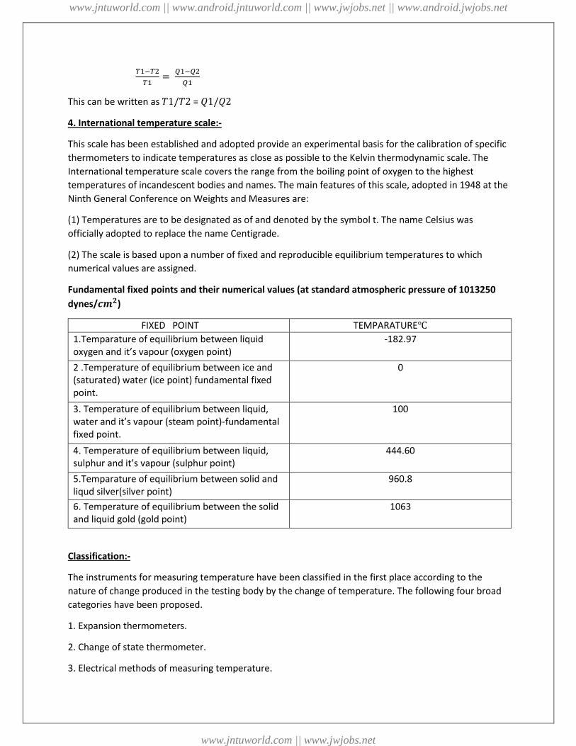
Liquid in glass thermometers:-
The liquid in gas thermometers is one of the most common types of temp measuring devices. The unit
consists of glass envelope, responsive liquid and indicating scale.
Liquid range℃
Mercury -3.5 to 510
Alcohol -80 to 70
Toluene -80 to 100
Peutane -200 to 30
Creosote -5 to 200
www.jntuworld.com || www.android.jntuworld.com || www.jwjobs.net || www.android.jwjobs.net
www.jntuworld.com || www.jwjobs.net
The choice in the type 𝑜𝑓 𝑔𝑙𝑎𝑠𝑠 𝑢𝑠𝑒𝑑 𝑖𝑠 𝑎 𝑚𝑎𝑡𝑒𝑟 of economics influenced by the range of the
thermometer. Higher the range, higher the cost. For temperature up to 450 ℃normal glass used.at high
temp up to 550℃. Above this temp quartz thermometers have been used.
Salient features/characteristics:-
1. Low cost and simplicity of use
2. Portable
3. Ease of checking for physical damage
4. Absence of need for auxiliary instruments.
5. No need of additional indicating instruments
6. Range limited to about 600℃.
Calibration of liquid in glass thermometer:-
1. Complete immersion
2. Total immersion
3. Partial immersion
Correction factor 𝑐𝑆= 0.00018N(T1-T2)
𝐶𝑠=Stem Correction In Degrees To Be Added algebrically To The Indicated Temp
N= Numberof degrees of exposed
T1= Reading of the primary thermometer and
T2= Average temperature of exposed stem.
Liquid in metal thermometers:-
The two distinct disadvantages of liquid in glass thermometers are
1. The glass is very fragile and hence care should be taken in handling these thermometers.
www.jntuworld.com || www.android.jntuworld.com || www.jwjobs.net || www.android.jwjobs.net
www.jntuworld.com || www.jwjobs.net

2. The position of the thermometer for accurate temp measurement is not always the best
position for reading the scale of the thermometer
Both of these disadvantages are overcome in mercury in steel thermometer. The principle of operation
is again the differential expansion of liquid which is used.
(i) a temperature sensitive element (bulb) filled with expanding fluid
(ii) a flexible capillary tube
(iii) a pressure or volume sensitive device such as Bourdon tube, bellows or diaphragms, and
(iv) a device for indicating or recording a signal related to the measured temperature.
Advantages and limitations :
* Simple and inexpensive design of the system
* Quite rugged construction, minimum possibility of, damage or failure in shipment, installation and use
* Fairly good response, accuracy and sensitivity
* Remote indication upto about 100 m possible with capillary lines.
Gas Thermometer:-
This system is defined as "a thermal system with a gas and operating on the principle of pressure change
with temperature change". The expansion, of a gas is governed by the ideal gas law:
PV = RT; P = (RT/V)
www.jntuworld.com || www.android.jntuworld.com || www.jwjobs.net || www.android.jwjobs.net
www.jntuworld.com || www.jwjobs.net

Gas: Nitrogen gas
Range: -130°to 540°
The volume of gas required in the bulb is determined by the gas expansion and by the temperature
range of the instrument.
V = R (𝑇2− 𝑇1
𝑃2− 𝑃2)
Where subscripts 1, 2 refer to the conditions at the lowest and highest points of the scale.
Electrical Methods:-
In electrical methods of measuring temperature, the temperature signal is converted into electrical
signal either through a change in resistance or voltage development of emf.
1. Resistance Thermometers
2. Thermistors
3. Thermo couples
1. Resistance Thermometers:
www.jntuworld.com || www.android.jntuworld.com || www.jwjobs.net || www.android.jwjobs.net
www.jntuworld.com || www.jwjobs.net

The thermometer comprises a resistance element or bulb, suitable electrical leads and an indicating -
recording or resistance measuring instrument. The resistance element is, usually in the form of a coil of
very fine platinum, nickel or copper wound non -conductively. Onto an insulating ceramic former which
is protected externally by a metal sheath. A laboratory type of resistance thermometer is often wound
on a crossed mica former and enclosed in a pyrex tube. The tube may be evacuated or filled with an
inert gas to protect the metal wire. Care is to be taken to ensure that the resistance wire is free from m
mechanical stresses. A metal which has been strained will suffer a change in the resistance
characteristics; the metal is therefore usually annealed at a temperature higher than that at which it is
so operate.
Platinum is preferred because,
1. Physically stable (i.e., relatively indifferent to its environment, resists corrosion and chemical
attack and is not readily oxidised) and has high electrical resistance characteristics.
2. Accuracy attainable with a platinum resistance thermometer is of the order of ± 0.01 of upto
500° 𝐶 and within ± 0. 1°𝐶 of upto 1200 °𝐶.
Advantages:-
* Simplicity and accuracy of operation
* Possibility of easy installation and replacement of sensitive bulb
www.jntuworld.com || www.android.jntuworld.com || www.jwjobs.net || www.android.jwjobs.net
www.jntuworld.com || www.jwjobs.net
* Easy check on the accuracy of the measuring circuit 'by substituting a standard resistance for the
resistance element.
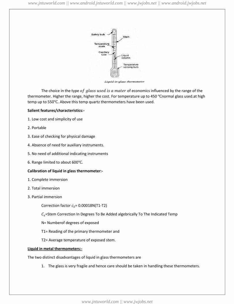
2. Thermistors:
Thermistors is a contraction of term Thermal Resistor. They are essentially semi-conductors which
behave as resistors with a high negative temperature coefficient. As -the temperature increases, the
resistance goes down, and as the temperature decreases, the resistance goes up. This is just opposite to
the effect of temperature changes on metals.
Thermistors are composed of sintered mixture of metallic oxides such as manganese. Nickel, cobalt,
copper, iron and uranium. These metallic oxides are milled, mixed in appropriate proportions, are
pressed into the desired shape with appropriate binders and finally sintered the electrical terminals are
either embedded before sintering or baked afterwards. The electrical characteristics of thermistors are
controlled by varying the type of oxide used and physical size and configuration of the thermistor.
Thermistors may be shaped in the form of beads, disks, washers, rods and `these standard forms are
shown in Fig.
www.jntuworld.com || www.android.jntuworld.com || www.jwjobs.net || www.android.jwjobs.net
www.jntuworld.com || www.jwjobs.net

The mathematical expression for the relation- ship between the resistance of a thermistor and absolute
temperature of thermistor is
3. Thermo couples:
The basic principle of temperature measurement by thermo-electricity was discovered by Seebeck in
1821 and is illustrated in Fig. 10.20. When two conductors of dissimilar metals M1 and M2 are joined
together to form a loop (a thermocouple) and two unequal temperatures Tl1 and T2 are imposed at the
two interface connections, an electric current we through the loop.
Experimentally it has been found that -the magnitude of the current is directly related to the two
materials M1 and M2, and the temperature difference (T1 – T2 ). In the practical application of the
effect, a suitable device is incorporated in the circuit to indicate any electromotive force or Bower
current. For convenience of measurement and standardization, one of the two junctions is usually
maintained at some constant known temperature. The output voltage of the circuit then indicates the
temperature difference relative to the reference temperature. Most tabulations set the reference value
to the triple point of water (O°𝐶).
Thermo-electric effects arise in two ways:
* a potential difference always exists between two dissimilar metals in contact with each other (Peltier
effect)
* a potential gradient exists even in a single conductor having & temperature gradient (Thomson effect)
In commercial instruments, the thermocouple materials are so chosen that the Peltier and Thomson
emfs act in such a manner that the combined value is maximum and that varies directly with
temperature.
www.jntuworld.com || www.android.jntuworld.com || www.jwjobs.net || www.android.jwjobs.net
www.jntuworld.com || www.jwjobs.net
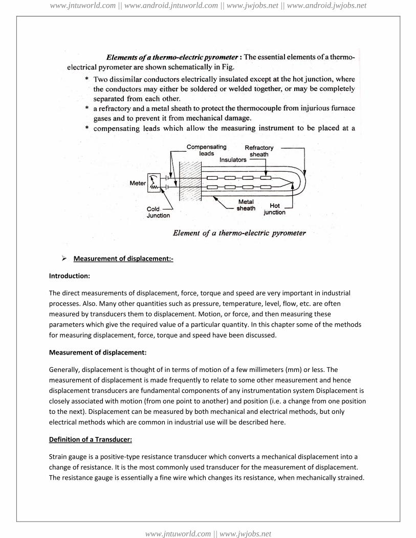
Measurement of displacement:-
Introduction:
The direct measurements of displacement, force, torque and speed are very important in industrial
processes. Also. Many other quantities such as pressure, temperature, level, flow, etc. are often
measured by transducers them to displacement. Motion, or force, and then measuring these
parameters which give the required value of a particular quantity. In this chapter some of the methods
for measuring displacement, force, torque and speed have been discussed.
Measurement of displacement:
Generally, displacement is thought of in terms of motion of a few millimeters (mm) or less. The
measurement of displacement is made frequently to relate to some other measurement and hence
displacement transducers are fundamental components of any instrumentation system Displacement is
closely associated with motion (from one point to another) and position (i.e. a change from one position
to the next). Displacement can be measured by both mechanical and electrical methods, but only
electrical methods which are common in industrial use will be described here.
Definition of a Transducer:
Strain gauge is a positive-type resistance transducer which converts a mechanical displacement into a
change of resistance. It is the most commonly used transducer for the measurement of displacement.
The resistance gauge is essentially a fine wire which changes its resistance, when mechanically strained.
www.jntuworld.com || www.android.jntuworld.com || www.jwjobs.net || www.android.jwjobs.net
www.jntuworld.com || www.jwjobs.net

Due to physical effects. Its length and cross-sectional area vary and a change of electrical resistivity also
occurs.
A transducer perform the following functions:
i. detects or senses the present and changes in physical quantity being measured.
ii. Provided a proportional output signal.
The strain Range is mounted to the measured surface so that it elongates or contracts with that surface.
This deformation of the sensing materials causes it to undergo a change in resistance.
Classification of transducers:-
Transducers are broadly classified into two groups as follows:
1. Active transducers (self-generating type)
2. Passive transducers (Externally powered)
1. Active transducers (self-generating type):
Active transducers are self-generating type. They do not required electric energy. They work on the
principle of conservation of energy. The energy required for production of an output signal is obtained
from the input or physical phenomenon being measured.
Examples: Thermo couples, Thermoelectric and Piezo-electric devices….etc.
2. Passive transducers (Externally powered):
Passive transducers are externally powered type. Passive transducers are based on principle of energy
controlling and they required a secondary electrical source for operation.
Examples: LVDT (Linear variable differential transformer), Thermistors, resistance thermometers, strain
gauge devices.
Classification based on the type of output:
1. Analog Transducer
2. Digital Transducer
1. Analog Transducer:
These transducers convert the input physical phenomenon into an analog output (analog form) which is
continuous function of time.
Examples: Thermistor, Thermocouple, strain gauge, LVDT.
www.jntuworld.com || www.android.jntuworld.com || www.jwjobs.net || www.android.jwjobs.net
www.jntuworld.com || www.jwjobs.net
2. Digital Transducer:
These transducers convert the input physical phenomenon into an electrical output (digital form) which
may be in the form of pulses.
Examples: Turbine flow meter.
Classification based on the electrical principle involved:
1. Variable resistance type
(a) Strain and pressure gauge
(b) Thermistors, resistance thermo meters
(c) Photo conductive cell
2. Variable inductance type
(a) LVDT
(b) Reluctance pickup
(c) Eddy current type
3. Variable capacitance type
(a) Capacitor micro phase
(b) Pressure gauge
(c) Di electric gauge
4. Voltage generating type
(a) Thermo couple
(b) Photo voltaic cell
(c) Rotational motion tachometer
(d) Piezo- electric pickup
5. Voltage divider type
(a) Potentiometer position sensor
(b) Pressure actuated voltage divider
According to the principle of operation, transducer for the measurement of displacement:
www.jntuworld.com || www.android.jntuworld.com || www.jwjobs.net || www.android.jwjobs.net
www.jntuworld.com || www.jwjobs.net
1. Variable resistance transducer
2. Variable inductance transducer
3. Variable capacitance transducer
4. Piezo electric transducer
5. Photo electric or light detecting transducer
(a) Photo conductive
(b) Photo voltaic
(c) Photo emissive
6. Ionization transducers.
Advantages of electrical transducers over other transducers:
1. Mass and inertia effects are minimized
2. Amplification or attenuation is minimized
3. Effect of friction is minimized
4. They are compact in size
5. Remote indication is possible
6. Power consumption is less and loading errors are minimized.
Limitations:-
1. They need external power supply, 2. High cost
3. Instrument electrical properties may change the actual reading of the variable which is to be
measured.
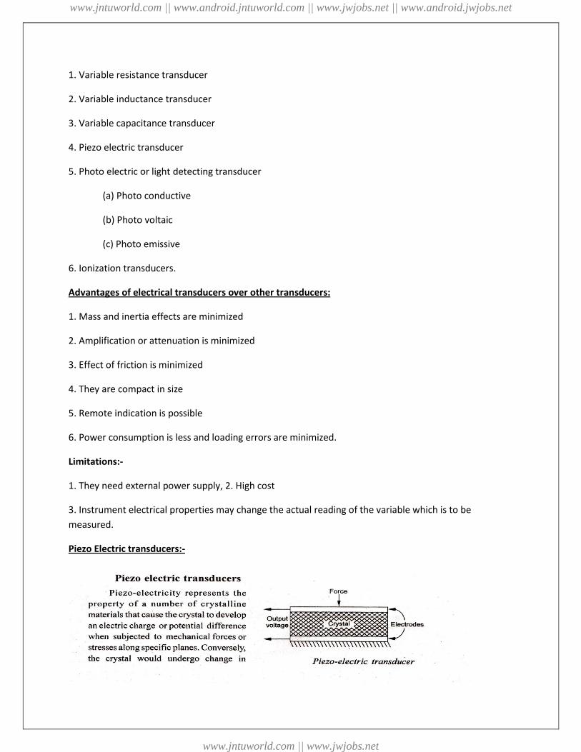
Piezo Electric transducers:-
www.jntuworld.com || www.android.jntuworld.com || www.jwjobs.net || www.android.jwjobs.net
www.jntuworld.com || www.jwjobs.net
thickness (and thus produce mechanical forces) when charged electrically by a potential difference
applied to its proper axis. Elements exhibiting piezo-electric qualities are sometimes known as electro
restrictive elements.
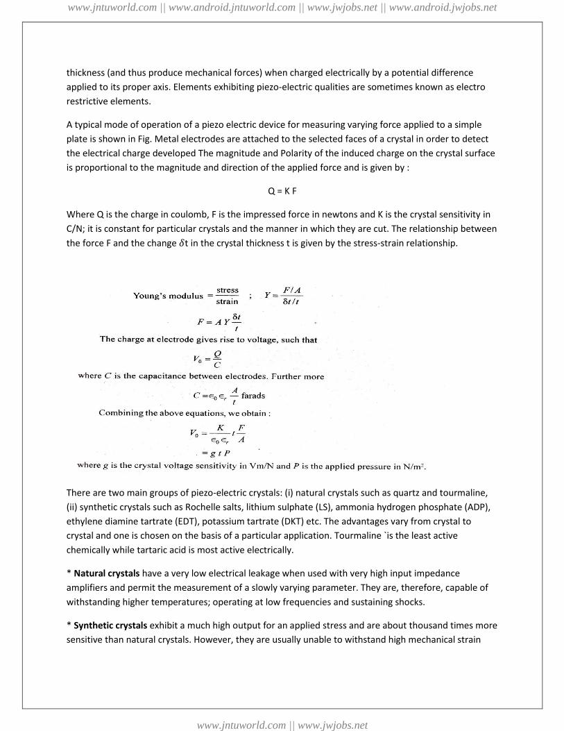
A typical mode of operation of a piezo electric device for measuring varying force applied to a simple
plate is shown in Fig. Metal electrodes are attached to the selected faces of a crystal in order to detect
the electrical charge developed The magnitude and Polarity of the induced charge on the crystal surface
is proportional to the magnitude and direction of the applied force and is given by :
Q = K F
Where Q is the charge in coulomb, F is the impressed force in newtons and K is the crystal sensitivity in
C/N; it is constant for particular crystals and the manner in which they are cut. The relationship between
the force F and the change 𝛿t in the crystal thickness t is given by the stress-strain relationship.
There are two main groups of piezo-electric crystals: (i) natural crystals such as quartz and tourmaline,
(ii) synthetic crystals such as Rochelle salts, lithium sulphate (LS), ammonia hydrogen phosphate (ADP),
ethylene diamine tartrate (EDT), potassium tartrate (DKT) etc. The advantages vary from crystal to
crystal and one is chosen on the basis of a particular application. Tourmaline `is the least active
chemically while tartaric acid is most active electrically.
* Natural crystals have a very low electrical leakage when used with very high input impedance
amplifiers and permit the measurement of a slowly varying parameter. They are, therefore, capable of
withstanding higher temperatures; operating at low frequencies and sustaining shocks.
* Synthetic crystals exhibit a much high output for an applied stress and are about thousand times more
sensitive than natural crystals. However, they are usually unable to withstand high mechanical strain
www.jntuworld.com || www.android.jntuworld.com || www.jwjobs.net || www.android.jwjobs.net
www.jntuworld.com || www.jwjobs.net

without fracture. Further, the synthetic crystals have an accelerated rate of deterioration over the
natural ones.
The major advantages of piezoelectric transducers are:
* High frequency response,
* High output,
* Rugged construction
* Negligible phase shift, and
* Small size. The small size of the transducer is especially useful for accelerometers where added
mass will mechanically load a system.
Applications: Piezo-electric transducers are most often used for accelerometers, pressure cells and
force cells in that order.
Resistance Transducers:-
Variable resistance transducers:-
In terms of physical quantities, the equation for electrical resistance of a metal conductor is
𝑅 = 𝜌 𝑙
𝐴
www.jntuworld.com || www.android.jntuworld.com || www.jwjobs.net || www.android.jwjobs.net
www.jntuworld.com || www.jwjobs.net
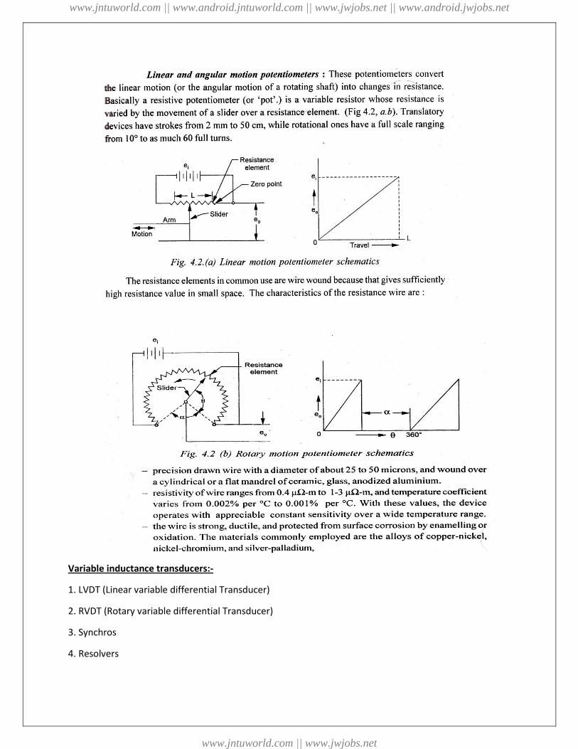
Variable inductance transducers:-
1. LVDT (Linear variable differential Transducer)
2. RVDT (Rotary variable differential Transducer)
3. Synchros
4. Resolvers
www.jntuworld.com || www.android.jntuworld.com || www.jwjobs.net || www.android.jwjobs.net
www.jntuworld.com || www.jwjobs.net

1. LVDT (Linear variable differential Transducer):
The linear variable-differential transformer (LVDT) is the most widely used inductive transducer to
translate linear motion into electrical signal.
Construction: A differential transformer consists of a primary winding and two secondary windings. The
windings are arranged concentrically and next to each other. They are wound over a hollow bobbin
which is usually of a non-magnetic and insulating material, as shown in Fig.
Working: Any physical displacement of the core causes the voltage of one secondary winding to increase
while simultaneously, reducing the voltage in the other secondary winding. The difference of the two
voltages appears across the output terminals of the transducer and gives a measure of the physical
position of the core and hence the displacement.
When the core is in the neutral or zero position, voltages induced in the secondary windings are equal
and opposite and the net output is negligible. As the core is moved in one direction from the null
position, the differential voltage, i.e. the difference of the secondary voltages, will increase while
maintaining an in-phase relationship with the voltage from the input source. In the other direction from
the null position, the differential voltage will again increase, but will be 180' out of phase with the
voltage from the input source. By comparing the magnitude and phase of the output (differential)
voltage with the input source. The amount and direction of movement of the core and hence of
displacement may be determined. Variation of output voltage with core position is shown in Fig.
Following are the advantages of LVDT:
(i) The output voltage of these transducer is practically linear for displacements upto 5 mm.
(ii) They have infinite resolution.
(iii) These transducers possess a high sensitivity.
(iv) These transducers can usually tolerate a high degree of shock and vibration without any adverse
effects.
(v) They are simple, light in weight, and easy to align and maintain.
www.jntuworld.com || www.android.jntuworld.com || www.jwjobs.net || www.android.jwjobs.net
www.jntuworld.com || www.jwjobs.net
Following are the disadvantages of LVDT:
(i) Rela6vely large displacements are required for appreciable differential output.
(ii) They are sensitive to stray magnetic fields but shielding is possible.
(iii) They are inherently low in power output.
2. RVDT (Rotary variable differential Transducer):
A RVDT is used to convert rectangular displacement into electrical signal. The construction and working
of RVDT is same as that of LVDT except that is employs a cam shaped core. This core rotates between
the primary and two secondary windings with the help of shaft.
3. Synchros:
The devices by which the angular position of shaft is converted into electrical signal are known as
synchros. The synchros are electromagnetic transducers. The construction of synchro is same as a three
phase alternator. It has a stator and a rotor. The stator consists of 3 identical stationary windings which
are separated by 120° in space. These stationary windings are connected in star (Y) configuration.
The rotor is dumb-bell shaped rotor to which an AC excitation voltage is applied through slip rings. The
rotor acts as primary winding of single phase transformer where as the stationary windings act as
secondary winding of single phase & transformer. There are two basic parts m a synchro system namely
synchro transmitter and synchro receiver.
4. Resolvers:
It is an electromagnetic device which consists of two stator windings and two rotor windings. Resolving
is nothing but converting from one co-ordinate system to another coordinate system. The resolvers
converts the shafts angular position into Cartesian coordinates i.e., the angular rotor position is
converted into those signals which are proportional to the sine and cosine of the rotor position and this
is carried out with respect to the position of the stators.
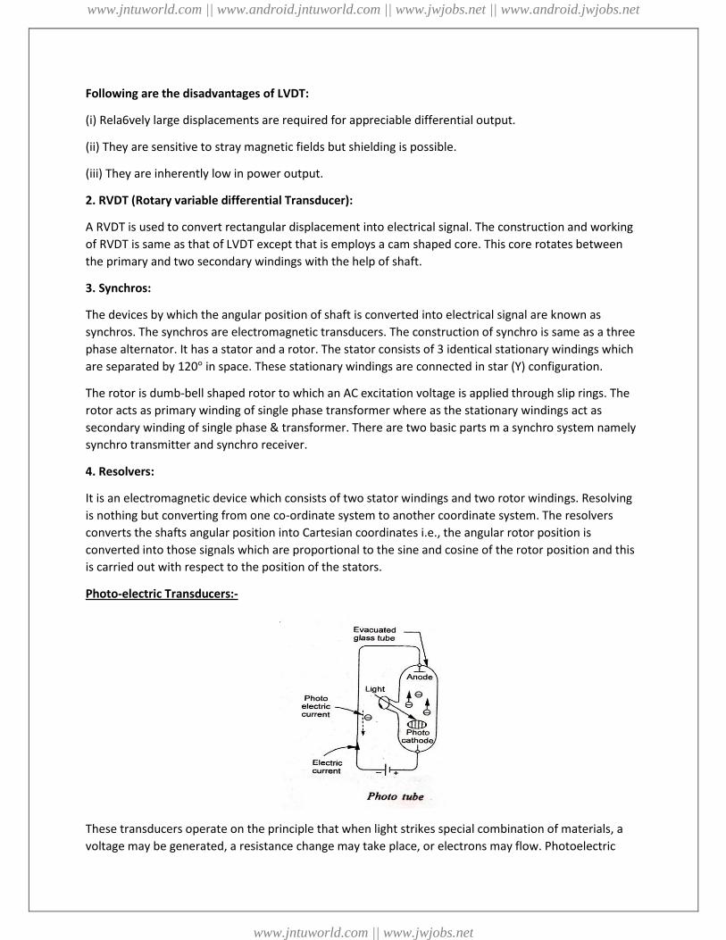
Photo-electric Transducers:-
These transducers operate on the principle that when light strikes special combination of materials, a
voltage may be generated, a resistance change may take place, or electrons may flow. Photoelectric
www.jntuworld.com || www.android.jntuworld.com || www.jwjobs.net || www.android.jwjobs.net
www.jntuworld.com || www.jwjobs.net

cells are used for a wide variety of purposes in control engineering for precision measuring devices, in
exposure meters used in photography. They are also used in solar batteries as sources of electrical
power for rockets and satellites used in space research.
Based on the principle of rotation photo electric transducers are classified into the 3 types. They are,
(i) Photo-emissive cell: These transducers operate on the photo-emissive effect, i.e., when certain types
of materials are exposed to light, electrons readmitted and a current flow is produced. Light sensitive
photo-cathode may consist of a very thin film of cesium deposited by isotonic onto an oxidised silver
base. Light strikes the cathode, causing the emission electrons which are attracted towards the anode.
This phenomenon produces flow of it current in the external circuit; the current being a function of
radiant energy striking the cathode.
Light information ------------------ current information
(ii) Photo-conductive cell: These are the variable resistance transducers. They on the principle of photo
conductive effect, i.e., some special type of semiconductor oils change their resistance when exposed to
light.
Light information ------------------ resistance information
Figure shows schematically the construction and electrical circuit of a photoconductive cell. The
sensitive material usually employed is cadmium selenide, germanium etc in the form of thin coating
between the two electrodes on a glass. Further, the cells are used in the circuit as a variable resistance
and are put in .series an ammeter and a voltage source. When the light strikes the semiconductor
material, is a decrease in the cell resistance thereby producing an increase in the current indicated the
ammeter.
www.jntuworld.com || www.android.jntuworld.com || www.jwjobs.net || www.android.jwjobs.net
www.jntuworld.com || www.jwjobs.net
(iii) Photo-voltaic cell: These transducers operate on the photo-valtaic effect, i.e., when light's trikes a
junction of certain dissimilar metals, a potential difference is built up.
Light information ------------------ emf information
The cell consists of a metal base plate, a non-metal semiconductor and a thin transparent metallic layer.
Typical examples of the layers are the copper oxide on copper and iron oxide on iron combination. The
transparent layer may be in the form of a sprayed conducting lacquer. Light strikes the coating and
generates an electric potential. The output is, however, low and is non-linear function of the light
intensity. In contrasted photo-tube and photo-conductive cells, the photo-voltaic unit is self-gene, rated
and requires no voltage source to operate it.
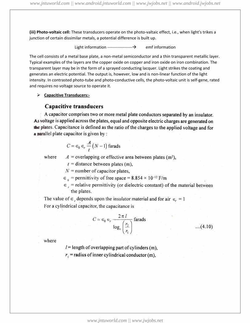
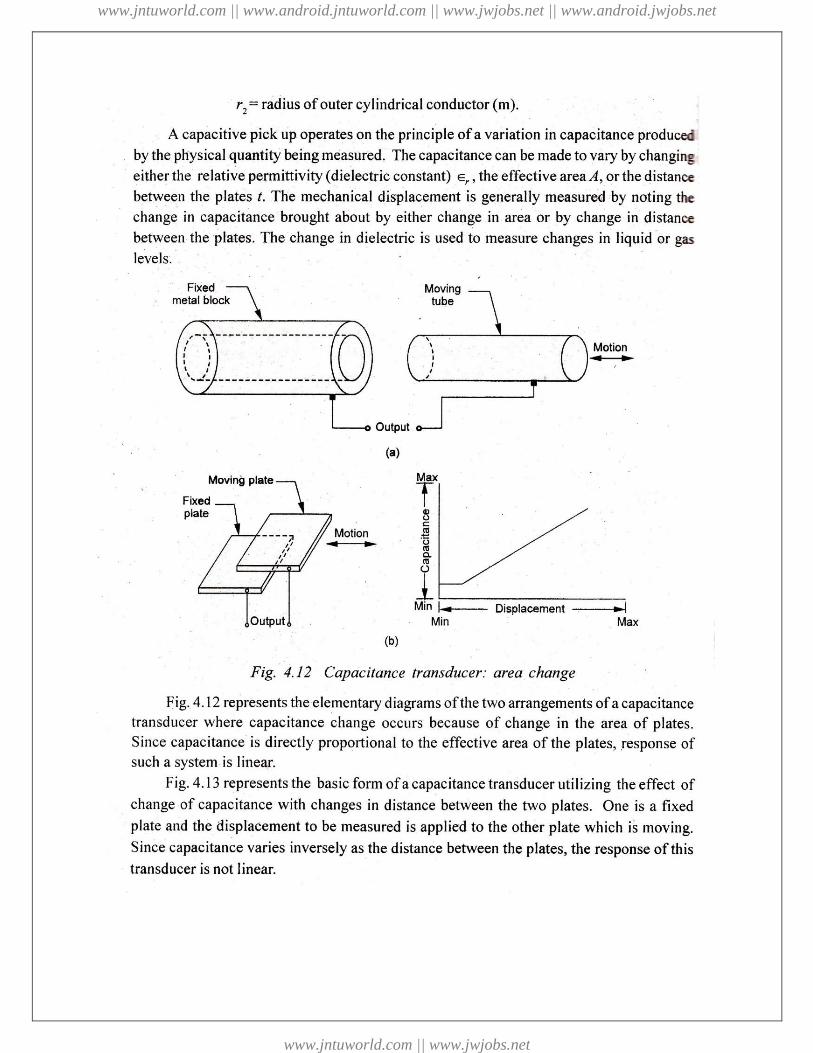
Capacitive Transducers:-
www.jntuworld.com || www.android.jntuworld.com || www.jwjobs.net || www.android.jwjobs.net
www.jntuworld.com || www.jwjobs.net
www.jntuworld.com || www.android.jntuworld.com || www.jwjobs.net || www.android.jwjobs.net
www.jntuworld.com || www.jwjobs.net

www.jntuworld.com || www.android.jntuworld.com || www.jwjobs.net || www.android.jwjobs.net
www.jntuworld.com || www.jwjobs.net
Related Documents
![UNIT_2 1 DATABASE MANAGEMENT SYSTEM[DBMS] 2620003 [Unit: 2] Prepared By Lavlesh Pandit SPCE MCA, Visnagar.](https://static.cupdf.com/doc/110x72/56649f385503460f94c5526a/unit2-1-database-management-systemdbms-2620003-unit-2-prepared-by-lavlesh.jpg)