1 UNIT - V AC VOLTAGE CONTROLLER AND CYCLOCONVERTER (RMS VOLTAGE CONTROLLERS) AC voltage controllers (ac line voltage controllers) are employed to vary the RMS value of the alternating voltage applied to a load circuit by introducing Thyristors between the load and a constant voltage ac source. The RMS value of alternating voltage applied to a load circuit is controlled by controlling the triggering angle of the Thyristors in the ac voltage controller circuits. In brief, an ac voltage controller is a type of thyristor power converter which is used to convert a fixed voltage, fixed frequency ac input supply to obtain a variable voltage ac output. The RMS value of the ac output voltage and the ac power flow to the load is controlled by varying (adjusting) the trigger angle ‘’ There are two different types of thyristor control used in practice to control the ac power flow 1. On-Off control 2. Phase control These are the two ac output voltage control techniques. In On-Off control technique Thyristors are used as switches to connect the load circuit to the ac supply (source) for a few cycles of the input ac supply and then to disconnect it for few input cycles. The Thyristors thus act as a high speed contactor (or high speed ac switch). PHASE CONTROL In phase control the Thyristors are used as switches to connect the load circuit to the input ac supply, for a part of every input cycle. That is the ac supply voltage is chopped using Thyristors during a part of each input cycle. The thyristor switch is turned on for a part of every half cycle, so that input supply voltage appears across the load and then turned off during the remaining part of input half cycle to disconnect the ac supply from the load. By controlling the phase angle or the trigger angle ‘’ (delay angle), the output RMS voltage across the load can be controlled. The trigger delay angle ‘’ is defined as the phase angle (the value of t) at which the thyristor turns on and the load current begins to flow. Thyristor ac voltage controllers use ac line commutation or ac phase commutation. Thyristors in ac voltage controllers are line commutated (phase commutated) since the input supply is ac. When the input ac voltage reverses and becomes negative during the negative half AC Voltage Controller V 0(RMS) f S Variable AC RMSO/P Voltage AC Input Voltage f s V s f s

Welcome message from author
This document is posted to help you gain knowledge. Please leave a comment to let me know what you think about it! Share it to your friends and learn new things together.
Transcript
1
UNIT - V
AC VOLTAGE CONTROLLER AND CYCLOCONVERTER
(RMS VOLTAGE CONTROLLERS)
AC voltage controllers (ac line voltage controllers) are employed to vary the RMS value
of the alternating voltage applied to a load circuit by introducing Thyristors between the load
and a constant voltage ac source. The RMS value of alternating voltage applied to a load circuit
is controlled by controlling the triggering angle of the Thyristors in the ac voltage controller
circuits.
In brief, an ac voltage controller is a type of thyristor power converter which is used to
convert a fixed voltage, fixed frequency ac input supply to obtain a variable voltage ac output.
The RMS value of the ac output voltage and the ac power flow to the load is controlled by
varying (adjusting) the trigger angle ‘’
There are two different types of thyristor control used in practice to control the ac power
flow
1. On-Off control
2. Phase control
These are the two ac output voltage control techniques.
In On-Off control technique Thyristors are used as switches to connect the load circuit to
the ac supply (source) for a few cycles of the input ac supply and then to disconnect it for few
input cycles. The Thyristors thus act as a high speed contactor (or high speed ac switch).
PHASE CONTROL
In phase control the Thyristors are used as switches to connect the load circuit to the
input ac supply, for a part of every input cycle. That is the ac supply voltage is chopped using
Thyristors during a part of each input cycle.
The thyristor switch is turned on for a part of every half cycle, so that input supply
voltage appears across the load and then turned off during the remaining part of input half cycle
to disconnect the ac supply from the load.
By controlling the phase angle or the trigger angle ‘’ (delay angle), the output RMS
voltage across the load can be controlled.
The trigger delay angle ‘’ is defined as the phase angle (the value of t) at which the
thyristor turns on and the load current begins to flow.
Thyristor ac voltage controllers use ac line commutation or ac phase commutation.
Thyristors in ac voltage controllers are line commutated (phase commutated) since the input
supply is ac. When the input ac voltage reverses and becomes negative during the negative half
AC
VoltageController
V0(RMS)
fS
Variable AC
RMS O/P Voltage
AC
Input
Voltage
fs
Vs
fs

2
cycle the current flowing through the conducting thyristor decreases and falls to zero. Thus the
ON thyristor naturally turns off, when the device current falls to zero.
Phase control Thyristors which are relatively inexpensive, converter grade Thyristors
which are slower than fast switching inverter grade Thyristors are normally used.
For applications upto 400Hz, if Triacs are available to meet the voltage and current
ratings of a particular application, Triacs are more commonly used.
Due to ac line commutation or natural commutation, there is no need of extra
commutation circuitry or components and the circuits for ac voltage controllers are very simple.
Due to the nature of the output waveforms, the analysis, derivations of expressions for
performance parameters are not simple, especially for the phase controlled ac voltage
controllers with RL load. But however most of the practical loads are of the RL type and hence
RL load should be considered in the analysis and design of ac voltage controller circuits.
TYPE OF AC VOLTAGE CONTROLLERS
The ac voltage controllers are classified into two types based on the type of input ac
supply applied to the circuit.
Single Phase AC Controllers.
Three Phase AC Controllers.
Single phase ac controllers operate with single phase ac supply voltage of 230V RMS
at 50Hz in our country. Three phase ac controllers operate with 3 phase ac supply of 400V
RMS at 50Hz supply frequency.
Each type of controller may be sub divided into
Uni-directional or half wave ac controller.
Bi-directional or full wave ac controller.
In brief different types of ac voltage controllers are
Single phase half wave ac voltage controller (uni-directional controller).
Single phase full wave ac voltage controller (bi-directional controller).
Three phase half wave ac voltage controller (uni-directional controller).
Three phase full wave ac voltage controller (bi-directional controller).
APPLICATIONS OF AC VOLTAGE CONTROLLERS
Lighting / Illumination control in ac power circuits.
Induction heating.
Industrial heating & Domestic heating.
Transformer tap changing (on load transformer tap changing).
Speed control of induction motors (single phase and poly phase ac induction motor
control).
AC magnet controls.
PRINCIPLE OF ON-OFF CONTROL TECHNIQUE (INTEGRAL CYCLE
CONTROL)
The basic principle of on-off control technique is explained with reference to a single
phase full wave ac voltage controller circuit shown below. The thyristor switches 1T and
are turned on by applying appropriate gate trigger pulses to connect the input ac supply to the
load for ‘n’ number of input cycles during the time interval . The thyristor switches 1T and
are turned off by blocking the gate trigger pulses for ‘m’ number of input cycles during the
2T
ONt
2T

3
time interval . The ac controller ON time usually consists of an integral number of
input cycles.
= Load Resistance
Fig.: Single phase full wave AC voltage controller circuit
Fig.: Waveforms
Example
Referring to the waveforms of ON-OFF control technique in the above diagram,
Two input cycles. Thyristors are turned ON during for two input cycles.
One input cycle. Thyristors are turned OFF during for one input cycle
OFFt ONt
LR R
Vs
Vo
io
ig1
ig2
wt
wt
wt
wt
Gate pulse of T1
Gate pulse of T2
n m
n ONt
m OFFt

4
Fig.: Power Factor
Thyristors are turned ON precisely at the zero voltage crossings of the input supply.
The thyristor is turned on at the beginning of each positive half cycle by applying the gate
trigger pulses to as shown, during the ON time . The load current flows in the positive
direction, which is the downward direction as shown in the circuit diagram when conducts.
The thyristor is turned on at the beginning of each negative half cycle, by applying gating
signal to the gate of , during . The load current flows in the reverse direction, which is
the upward direction when conducts. Thus we obtain a bi-directional load current flow
(alternating load current flow) in a ac voltage controller circuit, by triggering the thyristors
alternately.
This type of control is used in applications which have high mechanical inertia and high
thermal time constant (Industrial heating and speed control of ac motors). Due to zero voltage
and zero current switching of Thyristors, the harmonics generated by switching actions are
reduced.
For a sine wave input supply voltage,
RMS value of input ac supply = = RMS phase supply voltage.
If the input ac supply is connected to load for ‘n’ number of input cycles and
disconnected for ‘m’ number of input cycles, then
Where = input cycle time (time period) and
= input supply frequency.
= controller on time = .
= controller off time = .
= Output time period = .
We can show that,
1T
1T ONt
1T
2T
2T ONt
2T
sin 2 sins m Sv V t V t
SV 2
mV
,ON OFFt n T t m T
1T
f
f
ONt n T
OFFt m T
OT ON OFFt t nT mT

5
Output RMS voltage
Where is the RMS input supply voltage = .
TO DERIVE AN EXPRESSION FOR THE RMS VALUE OF OUTPUT VOLTAGE,
FOR ON-OFF CONTROL METHOD.
Output RMS voltage
Substituting for
Now = An integral number of input cycles; Hence
&
Where T is the input supply time period (T = input cycle time period). Thus we note that
ON ON
SO RMS i RMS
O O
t tV V V
T T
i RMSV
SV
2 2
0
1.
ONt
mO RMS
O t
V V Sin t d tT
2
2
0
.ONt
m
O RMS
O
VV Sin t d t
T
2 1 2
2
CosSin
2
0
1 2
2
ONt
m
O RMS
O
V Cos tV d t
T
2
0 0
2 .2
ON ONt t
m
O RMS
O
VV d t Cos t d t
T
2
0 0
2
22
ON ONt t
m
O RMS
O
V Sin tV t
T
2 sin 2 sin 0
02 2
m ONONO RMS
O
V tV t
T
ONt
, 2 ,3 ,4 ,5 ,.....ONt T T T T T 2 ,4 ,6 ,8 ,10 ,......ONt
sin 2 0ONt
2
2 2
m ON m ON
O RMS
O O
V t V tV
T T

6
Where = RMS value of input supply voltage;
= duty cycle (d).
PERFORMANCE PARAMETERS OF AC VOLTAGE CONTROLLERS
1. RMS Output (Load) Voltage
Where = RMS value of input supply voltage.
2. Duty Cycle
Where, = duty cycle (d).
3. RMS Load Current
; for a resistive load .
4. Output AC (Load) Power
ON ON
SO RMS i RMS
O O
t tV V V
T T
2
mSi RMS
VV V
ON ON
O ON OFF
t t nT nk
T t t nT mT n m
S SO RMS
nV V V k
m n
122
2 2
0
sin .2
mO RMS
nV V t d t
n m
2
mSO RMS i RMS
V nV V k V k
m n
SO RMS i RMSV V k V k
S i RMSV V
ON ON
O ON OFF
t t nTk
T t t m n T
n
km n
O RMS O RMS
O RMS
L
V VI
Z R
LZ R
2
O LO RMSP I R

7
5. Input Power Factor
; RMS input supply current.
The input supply current is same as the load current
Hence, RMS supply current = RMS load current; .
6. The Average Current of Thyristor
output load power
input supply volt amperes
O O
S S
P PPF
VA V I
2
LO RMS
i RMS in RMS
I RPF
V I
S in RMS
I I
in O LI I I
in RMS O RMSI I
2
LO RMS O RMS i RMS
i RMS in RMS i RMS i RMS
I R V V kPF k
V I V V
nPF k
m n
T AvgI
0 2 3 t
Im
nmiT
Waveform of Thyristor Current
0
sin .2
mT Avg
nI I t d t
m n
0
sin .2
m
T Avg
nII t d t
m n
0
cos2
m
T Avg
nII t
m n
cos cos0
2
m
T Avg
nII
m n
8
,
Where = maximum or peak thyristor current.
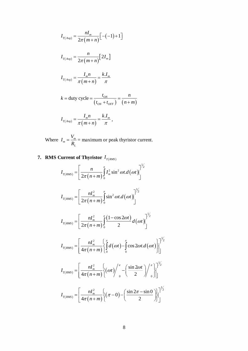
7. RMS Current of Thyristor
1 1
2
m
T Avg
nII
m n
2
2mT Avg
nI I
m n
.m m
T Avg
I n k II
m n
duty cycle ON
ON OFF
t nk
t t n m
.m m
T Avg
I n k II
m n
mm
L
VI
R
T RMSI
12
2 2
0
sin .2
mT RMS
nI I t d t
n m
122
2
0
sin .2
m
T RMS
nII t d t
n m
122
0
1 cos 2
2 2
m
T RMS
tnII d t
n m
122
0 0
cos 2 .4
m
T RMS
nII d t t d t
n m
122
0 0
sin 2
24
m
T RMS
nI tI t
n m
122
sin 2 sin 00
4 2
m
T RMS
nII
n m

9
PROBLEM
A single phase full wave ac voltage controller working on ON-OFF control technique
has supply voltage of 230V, RMS 50Hz, load = 50. The controller is ON for 30 cycles
and off for 40 cycles. Calculate
1. ON & OFF time intervals.
2. RMS output voltage.
3. Input P.F.
4. Average and RMS thyristor currents.
, V, ,
, .
= number of input cycles during which controller is ON; .
number of input cycles during which controller is OFF; .
= controller ON time.
= controller OFF time.
Duty cycle
RMS output voltage
122
0 04
m
T RMS
nII
n m
1 12 22 2
4 4
m m
T RMS
nI nII
n m n m
2 2
m m
T RMS
I InI k
m n
2
m
T RMS
II k
230in RMS
V V 2 230 325.269mV V 325.269mV V
1 10.02sec
50T
f Hz 20T ms
n 30n
m 40m
30 20 600 0.6secONt n T ms ms
0.6secONt n T
40 20 800 0.8secOFFt m T ms ms
0.8secOFFt m T
30
0.428540 30
nk
m n

10
Input Power Factor
Average Thyristor Current Rating
where
= Peak (maximum) thyristor current.
RMS Current Rating of Thyristor
O RMS i RMS
nV V
m n
30 3
230 23030 40 7
O RMSV V
230 0.42857 230 0.65465
O RMSV V
150.570O RMS
V V
150.5703.0114
50
O RMS O RMS
O RMS
L
V V VI A
Z R
2 23.0114 50 453.426498O LO RMS
P I R W
.P F k
30
0.428570
nPF
m n
0.654653PF
m m
T Avg
I k InI
m n
2 230 325.269
50 50
mm
L
VI
R
6.505382mI A
6.505382 3
7T Avg
I
0.88745T Avg
I A
6.505382 3
2 2 2 7
m m
T RMS
I InI k
m n
2.129386T RMS
I A
11
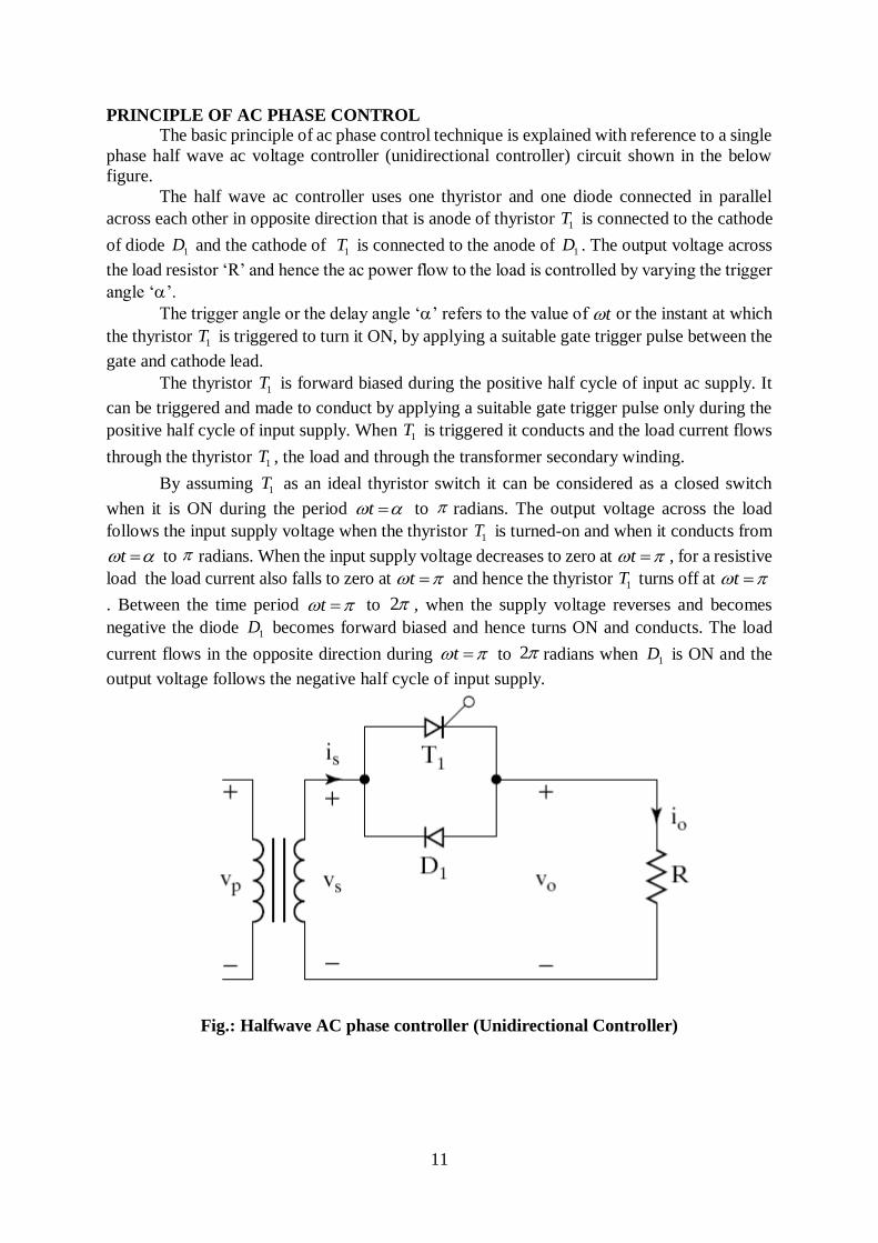
PRINCIPLE OF AC PHASE CONTROL
The basic principle of ac phase control technique is explained with reference to a single
phase half wave ac voltage controller (unidirectional controller) circuit shown in the below
figure.
The half wave ac controller uses one thyristor and one diode connected in parallel
across each other in opposite direction that is anode of thyristor is connected to the cathode
of diode and the cathode of is connected to the anode of . The output voltage across
the load resistor ‘R’ and hence the ac power flow to the load is controlled by varying the trigger
angle ‘’.
The trigger angle or the delay angle ‘’ refers to the value of or the instant at which
the thyristor is triggered to turn it ON, by applying a suitable gate trigger pulse between the
gate and cathode lead.
The thyristor is forward biased during the positive half cycle of input ac supply. It
can be triggered and made to conduct by applying a suitable gate trigger pulse only during the
positive half cycle of input supply. When is triggered it conducts and the load current flows
through the thyristor , the load and through the transformer secondary winding.
By assuming as an ideal thyristor switch it can be considered as a closed switch
when it is ON during the period to radians. The output voltage across the load
follows the input supply voltage when the thyristor is turned-on and when it conducts from
to radians. When the input supply voltage decreases to zero at , for a resistive
load the load current also falls to zero at and hence the thyristor turns off at
. Between the time period to , when the supply voltage reverses and becomes
negative the diode becomes forward biased and hence turns ON and conducts. The load
current flows in the opposite direction during to radians when is ON and the
output voltage follows the negative half cycle of input supply.
Fig.: Halfwave AC phase controller (Unidirectional Controller)
1T
1D 1T 1D
t
1T
1T
1T
1T
1T
t
1T
t t
t 1T t
t 2
1D
t 21D

12
Equations
Input AC Supply Voltage across the Transformer Secondary Winding.
= RMS value of secondary supply voltage.
Output Load Voltage
; for to
; for to .
Output Load Current
; for to .
; for to .
TO DERIVE AN EXPRESSION FOR RMS OUTPUT VOLTAGE
sins mv V t
2
mS in RMS
VV V
0o Lv v 0t
sino L mv v V t t 2
sino mo L
L L
v V ti i
R R
t 2
0o Li i 0t
O RMSV
2
2 21sin .
2mO RMS
V V t d t
22
1 cos 2.
2 2
m
O RMS
V tV d t

13
Where, = RMS value of input supply voltage (across the transformer
secondary winding).
Note: Output RMS voltage across the load is controlled by changing as indicated by the
expression for
22
1 cos 2 .4
m
O RMS
VV t d t
2 2
cos 2 .2
m
O RMS
VV d t t d t
2 2
sin 2
22
m
O RMS
V tV t
2
sin 22
22
m
O RMS
V tV
sin 4 sin 2
2 ;sin 4 02 22
m
O RMS
VV
sin 2
222
m
O RMS
VV
sin 2
222 2
m
O RMS
VV
1 sin 2
22 22
m
O RMS
VV
1 sin 2
22 2
O RMS i RMSV V
1 sin 2
22 2
SO RMSV V
2
mSi RMS
VV V
' '
O RMSV
14
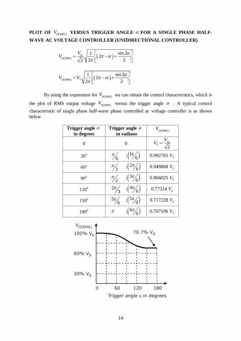
PLOT OF VERSUS TRIGGER ANGLE FOR A SINGLE PHASE HALF-
WAVE AC VOLTAGE CONTROLLER (UNIDIRECTIONAL CONTROLLER)
By using the expression for we can obtain the control characteristics, which is
the plot of RMS output voltage versus the trigger angle . A typical control
characteristic of single phase half-wave phase controlled ac voltage controller is as shown
below
Trigger angle
in degrees
Trigger angle
in radians
0 0
0.992765
0.949868
0.866025
0.77314
0.717228
0.707106
O RMSV
1 sin 2
22 22
m
O RMS
VV
1 sin 2
22 2
SO RMSV V
O RMSV
O RMSV
O RMS
V
2
mS
VV
0306
1;6
SV
0603
2;6
SV
0902
3;6
SV
0120 23
4;6
SV
0150 56
5;6
SV
0180 6;6
SV
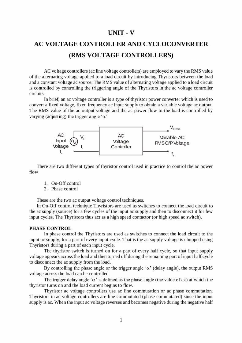
VO(RMS)
Trigger angle in degrees
0 60 120 180
100% VS
20% VS
60% VS
70.7% VS

15
Fig.: Control characteristics of single phase half-wave phase controlled ac voltage
controller
Note: We can observe from the control characteristics and the table given above that the range
of RMS output voltage control is from 100% of to 70.7% of when we vary the trigger
angle from zero to 180 degrees. Thus the half wave ac controller has the draw back of
limited range RMS output voltage control.
TO CALCULATE THE AVERAGE VALUE (DC VALUE) OF OUTPUT VOLTAGE
;
;
Hence
When is varied from 0 to . varies from 0 to
DISADVANTAGES OF SINGLE PHASE HALF WAVE AC VOLTAGE
CONTROLLER.
The output load voltage has a DC component because the two halves of the output
voltage waveform are not symmetrical with respect to ‘0’ level. The input supply
current waveform also has a DC component (average value) which can result in the
problem of core saturation of the input supply transformer.
The half wave ac voltage controller using a single thyristor and a single diode provides
control on the thyristor only in one half cycle of the input supply. Hence ac power flow
to the load can be controlled only in one half cycle.
Half wave ac voltage controller gives limited range of RMS output voltage control.
Because the RMS value of ac output voltage can be varied from a maximum of 100%
of at a trigger angle to a low of 70.7% of at .
These drawbacks of single phase half wave ac voltage controller can be over come by
using a single phase full wave ac voltage controller.
SV SV
2
1sin .
2mO dc
V V t d t
2
sin .2
m
O dc
VV t d t
2
cos2
m
O dc
VV t
cos 2 cos2
m
O dc
VV
cos2 1
cos 12
mdc
VV
2m SV V
2
cos 12
Sdc
VV
' ' dcV
mV
SV 0 SV Radians
16
APPLICATIONS OF RMS VOLTAGE CONTROLLER
Speed control of induction motor (polyphase ac induction motor).
Heater control circuits (industrial heating).
Welding power control.
Induction heating.
On load transformer tap changing.
Lighting control in ac circuits.
Ac magnet controls.
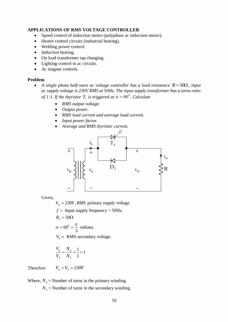
Problem
A single phase half-wave ac voltage controller has a load resistance , input
ac supply voltage is 230V RMS at 50Hz. The input supply transformer has a turns ratio
of 1:1. If the thyristor is triggered at . Calculate
RMS output voltage.
Output power.
RMS load current and average load current.
Input power factor.
Average and RMS thyristor current.
Given,
Therefore
Where, = Number of turns in the primary winding.
= Number of turns in the secondary winding.
50R
1T060
0
S
230 , primary supply voltage.
Input supply frequency = 50Hz.
50
60 radians.3
V RMS secondary voltage.
p
L
V V RMS
f
R
11
1
p p
S S
V N
V N
230p SV V V
pN
SN

17
RMS Value of Output (Load) Voltage
We have obtained the expression for as
RMS Load Current
Output Load Power
Input Power Factor
= RMS secondary supply voltage = 230V.
= RMS secondary supply current = RMS load current.
O RMSV
2
2 21sin .
2mO RMS
V V t d t
O RMSV
1 sin 2
22 2
SO RMSV V
01 sin120230 2
2 3 2O RMS
V
1
230 5.669 230 0.949862
O RMSV
218.4696 218.47 O RMS
V V V
O RMSI
218.469664.36939
50
O RMS
O RMS
L
VI Amps
R
OP
22 4.36939 50 954.5799 O LO RMS
P I R Watts
0.9545799 OP KW
O
S S
PPF
V I
SV
SI
4.36939 S O RMSI I Amps
954.5799 W
0.9498230 4.36939 W
PF
18
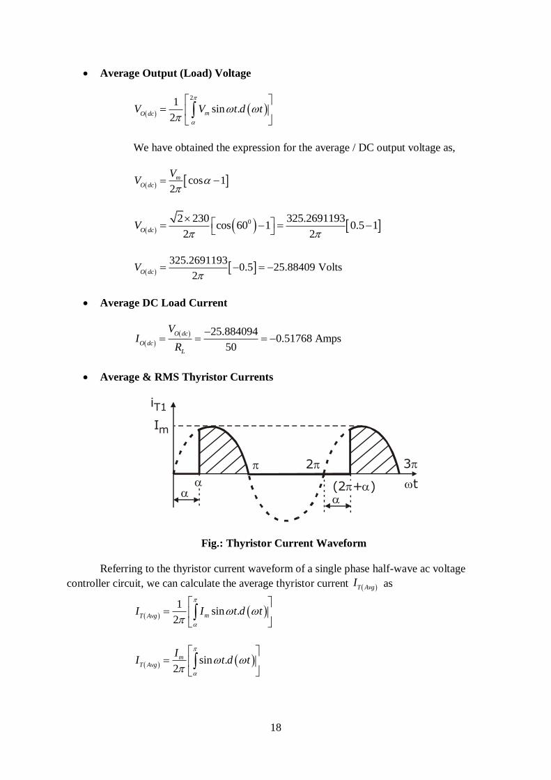
Average Output (Load) Voltage
We have obtained the expression for the average / DC output voltage as,
Average DC Load Current
Average & RMS Thyristor Currents
Fig.: Thyristor Current Waveform
Referring to the thyristor current waveform of a single phase half-wave ac voltage
controller circuit, we can calculate the average thyristor current as
2
1sin .
2mO dc
V V t d t
cos 12
m
O dc
VV
02 230 325.2691193cos 60 1 0.5 1
2 2O dc
V
325.2691193
0.5 25.88409 Volts2
O dcV
25.8840940.51768 Amps
50
O dc
O dc
L
VI
R
Im
iT1
2
(2 + )
3
t
T AvgI
1
sin .2
mT AvgI I t d t
sin .2
m
T Avg
II t d t

19
Where, = Peak thyristor current = Peak load current.
RMS thyristor current can be calculated by using the expression
cos2
m
T Avg
II t
cos cos2
m
T Avg
II
1 cos2
m
T Avg
II
mm
L
VI
R
2 230
50mI
6.505382 AmpsmI
1 cos2
m
T Avg
L
VI
R
02 2301 cos 60
2 50T Avg
I
2 230
1 0.5100
T AvgI
1.5530 AmpsT Avg
I
T RMSI
2 21sin .
2mT RMS
I I t d t
2 1 cos 2.
2 2
m
T RMS
tII d t
2
cos 2 .4
m
T RMS
II d t t d t
1 sin 2
24mT RMS
tI I t
20
1 sin 2 sin 2
4 2mT RMS
I I
1 sin 2
4 2mT RMS
I I
1 sin 2
2 22
m
T RMS
II
0sin 1206.50538 1
2 3 22T RMS
I
1 2 0.86602544.6
2 3 2T RMS
I
4.6 0.6342 2.91746T RMS
I A
2.91746 AmpsT RMS
I

21
UNIT – I
1. What is power electronics?
Power electronics is a subject that concerns the applications electronics principles
into situations that are rated at power level rather than signal level. It may be
defined as a subject deals with thw apparatus and equipment working on the
principle of electronics but at rated power level.
2. Give the applications of power electronics.
• Aerospace
• Commercial
• Industrial
• Telecommunications
3. Classify power semiconductor devices give examples.
• Diodes: power diodes
• Thyristors: SCR
• Control switches: BJT, MOSFET and IGBT
4. What are the types of power transistors?
• Bipolar Junction Transistor (BJT)
• Metal Oxide Semiconductor Field Effect Transistor (MOSFET)
• Insulated Gate Bipolar Transistor (IGBT)
5. Why IGBT is very popular nowadays?
a. Lower hate requirements
b. Lower switching losses
c. Smaller snubber circuit requirements
6. What are the different methods to turn on the thyristor?
a. Forward voltage triggering
b. Gate triggering
c. dv/dt triggering
d. Temperature triggering
e. Light triggering
7. What is the difference between power diode and signal diode?
S.No. Power diode Signal diode
1. Constructed with n-layer, called drift
region between p+ layer and n+ layer.
Drift region is not
present.
2. The
vol
tage,
Lower

22
cu
rrent and power
3. rPaotwinergsdairoedhesigopheer.r ate at
high speeds.
Operates at higher
switching speed.
8. IGBT is a voltage-controlled device. Why?
Because the controlling parameter is gate-emitter voltage.
9. Power MOSFET is a voltage-controlled device. Why?
Because the output (drain) current can be controlled by gate-source voltage.
10. Power BJT is a current controlled device. Why?
Because the output (collector) current can be controlled by base current.
11. What is the relation between α and β?
β = α
1 - α
α = β
1 – β
12. What are the different types of power MOSFET?
a. N-channel MOSFET
b. P-channel MOSFET
13. How can a thyristor turned off?
A thyristor can be turned off by making the current flowing through it to a level
below the holding current.
14. Define latching current.
The latching current is defined as the minimum value of anode current which
it must attain during turn on process to maintain conduction when gate signal
is removed.
15. Define holding current.
The holding current is defined as the minimum value of anode current below
which it must fall to for turning off the thyristor.
16. What is a snubber circuit?
It consists of a series combination of a resistor and a capacitor in parallel with the
thyristors. It is mainly used for dv / dt protection.
17. What losses occur in a thyristor during working conditions?
a. Forward conduction losses
b. Loss due to leakage current during forward and reverse blocking
c. Switching losses at turn-on and turn-off.
d. Gate triggering loss.

23
18. Define hard-driving or over-driving.
When gate current is several times higher than the minimum gate current required, a
thyristor is said to be hard-fired or over-driven. Hard-firing of a thyristor reduces its
turn-on time and enhances its di/dt capability.
19. Define circuit turn off time.
It is defined as the time during which a reverse voltage is applied across the
thyristor during its commutation process.
20. Why circuit turn off time should be greater than the thyristor turn-off
time?
Circuit turn off time should be greater than the thyristor turn-off time for reliable
turn-off, otherwise the device may turn-on at an undesired instant, a process called
commutation failure.
21. What is meant by commutation?
It is the process of changing the direction of current flow in a particular path of
the circuit. This process is used in thyristors for turning it off.
22. What are the types of commutation?
a. Natural commutation
b. Forced commutation
23. What is the turn-off time for converter grade SCRs and inverter grade SCRs?
Turn-off time for converter grade SCRs is 50 – 100 ms turn-off time for converter
grade SCRs and inverter grade SCRs and for inverter grade SCRs is 3 – 50 ms.
24. What are the advantages of GTO over SCR?oElimination commutating
components in forced commutation, resulting in reduction in cost, weight and
volume. oReduction in acoustic noise and electromagnetic noise due to elimination
of commutation chokes.
o Faster turn-off, permitting high switching frequencies.
o Improved efficiency of the converters.
25. Write down the applications of IGBT?
They are widely used for medium power applications.
AC and DC motor drives
UPS systems
Power supplies
Relays and Contactors
26. Compare Power MOSFET with BJT.
Power MOSFET BJT
1. Lower Switching loss Higher switching loss
24
2. High on state resistance so more lower conduction losses
conduction losses
3. Voltage controlled device Current controlled device
4. It has positive temperature coefficient. It has negative temperature
coefficient
27. Why IGBT is very popular now a days?
• Lower gate drive requirement
• Lower switching losses
• Smaller snubber circuit requirements
28. What are the different methods to turn on the thyristor?
Forward voltage triggering, Gate triggering, dv/dt triggering, temperature triggering
& light triggering
29. Define forward breakovervoltage .
When anode is positive w.r.to cathode with gate current open, the junction J1 & J3 are
forward biased but J2 is reverse biased. When the forward voltage is increased junction
J2 will have an avalanche breakdown at a voltage. This voltage is called forward
breakover voltage.
30. Define reverse breakovervoltage .
When cathode is positive w.r.to anode with gate current open, the junction J1 & J3 are
reverse biased but J2 is forward biased. When the reverse voltage is increased junctions
J1 & J3 will have an avalanche breakdown at a voltage. This voltage is called as critical
breakdown voltage Vbr.
31. IGBT is a voltage controlled device. Why?
IGBT is a voltage controlled device because the controlling parameter is gate emitter
voltage VGE
32. Power MOSFET is a voltage controlled device. Why?
Power MOSFET is a voltage controlled device because the output current can Controlled
by gate source voltage VGS.
33. What is meant by over drive factor?
It is defined as the ratio of IB & IBS
ODF = IB / IBS

25
UNIT – II
PHASE CONTROLLED CONVERTERS
1. What is meant by phase controlled rectifier?
It converts fixed ac voltage into variable dc voltage.
2. Mention some of the applications of controlled rectifier
Steel rolling mills, printing press, textile mills and paper mills employing dc motor drives, DC traction, Electro chemical and electro-metallurgical process, Portable hand tool drives, Magnet power supplies, HVDC
3. What is the function of freewheeling diodes in controlled rectifier?
4. It prevents the output voltage from becoming negative.
• The load current is transferred from the main thyristors to the freewheeling diode,
thereby allowing all of its thyristors to regain their blocking states.
5. What are the advantages of freewheeling diodes in a controlled in a controlled
rectifier?
• Input power factor is improved.
• Load current waveform is improved and thus the load performance is better.
6. What is meant by delay angle?
The delay angle is defined as the angle between the zero crossing of the input voltage and
the instant the thyristor is fired.
7. What are the advantages of single phase bridge converter over single phase
mid-point converter?
• SCRs are subjected to a peak-inverse voltage of 2Vm in a fully controlled bridge
rectifier. Hence for same voltage and currnt ratings of SCrs, power handled by mid-
point configuration is about

26
• In mid-point converter, each secondary winding should be able to supply the load
power. As such, the transformer rating in mid-point converter is double the load rating.
8. What is commutation angle or overlap angle?
The commutation period when outgoing and incoming thyristors are conducting is
known as overlap period. The angular period, when both devices share conduction is
known as the commutation angle or overlap angle.
9. What are the different methods of firing circuits for line
commutatedconverter?
• UJT firing circuit.
• The cosine wave crossing pulse timing control
• Digital firing schemes.
10. Give an expression for average voltage of single-phase semiconverters.
Average output voltage Vdc = (Vm / π) (1 + cos α).
11. What is meant by input power factor in controlled rectifier?
The input power factor is defined as the ratio of the total mean input power to the total
RMS input volt-amperes.
PF = ( V1 I1 cos φ1 ) / ( VrmsIrms)
12. What are the advantages of six-pulse converter?
• Commutation is made simple.
• Distortion on the ac side is reduced due to the reduction in lower order
harmonics.
• Inductance reduced in series is considerably reduced.
13. What are the disadvantages of continuous gating signal? More heating of the
SCR gate.
Increases the size of pulse transformer.
14. What is meant by high frequency carrier gating?
Thyristor is turned on by using a train of pulses from to. This type of signal is called as
high frequency carrier gating.
15. Define Displacement Factor.
The input displacement factor is defined as the cosine of the input displacement angle.
16. Define voltage ripple factor.
It is defined as the ratio of the net harmonic content of the output voltage to the average
output voltage.
17. is mean by uncontrolled rectifier?
The uncontrolled rectifier uses only diodes and it converts fixed ac voltage into fixed dc
voltage.

27
18. How to classify rectifier circuits. (i) Uncontrolled rectifier
(ii) Controlled rectifier
19. What is meant by full converter?
A fully controlled converter uses thyristors only and there is a wider control over the
level of dc output voltage. It is also known as two quadrant converter.
20. What are the performance factors of line commutated converters?
Input displacement angle , input power factor, DC voltage ratio, Input harmonic factor,
Voltage & current ripple factor.
21. What are the two configuration of single phase 2 pulse controlled rectifier?
• Mid-point converter
• Bridge Converter
22. What is meant by 2 pulse converter?
Two pulse converter is defined as two triggering pulses or two sets of triggering pulses are to be generated during every cycle of the supply to trigger the various SCRs.
23. What is meant by rectification mode in single phase fully controlled
converter?
In single phase full converter < 900
the voltage at the dc terminal is positive.
Therefore, power flows from source to load & the converter operates as a rectifier.
Source voltage is Vs & Current is positive. This is known as rectification mode.
24. What is meant by inversion mode?
In single phase full converter > 900
the voltage at the dc terminal is negative.
Therefore, power flows from load to source & the converter operates as line
commutated inverter. Source voltage Vs is negative & Current is positive. This is
known as inversion mode or synchronous mode.
25. What are the different types of controlled rectifier?
• According to input supply – Single phase controlled rectifier & Three phase
controlled rectifier
• According to Quadrant operation – semiconverter , full converter, dual
converter
• According to no. pulses / cycle – one pulse, two pulse, three pulse, Six pulse
& twelve pulse converter.
26. What are the difference between half controlled & fully controlled bridge
rectifier?
Half Controlled Bridge Rectifier
1. Power circuit consists of mixture of diodes & SCRs
2. It is one quadrant Converter
28
3. The Dc output voltage has limited control level.
4. Input power factor is more.
Full Controlled Bridge Rectifier
1. Power circuit consists of SCRs only
2. It is 2 quadrant Converter
3. The Dc output voltage has wider control level.
4. Input power factor is less.
27. What is meant continuous current operation of thyristor converter?
When a free wheeling diode is connected across the output, load current continuous
flow through the load. Whenever the load voltage tends to go to negative, freewheeling
diode starts conduct. As a result load current is transferred from SCR to freewheeling
diode. This is called continuous current operation osthyristor converter.
28. What is meant by sequence control of ac voltage regulators?
It means that the stages of voltage controllers in parallel triggered in a proper
sequence one after the other so as to obtain a variable output with low harmonic
content.
29. What are the advantages of sequence control of ac voltage regulators?
oSystem power factor is improved. oHarmonics are reduced in the source
current and the load voltage.
UNIT – III
DC – DC CHOPPERS
1. What is meant by commutation?
It is the process of changing the direction of current flow in a particular path of the
circuit. This process is used in thyristors for turning it off.
2. What are the types of commutation?
Natural commutation

29
Forced commutation
3. What is meant by natural commutation?
Here the current flowing through the thyristor goes through a natural zero and enable
the thyristor to turn off.
4. What is meant by forced commutation?
In this commutation, the current flowing through the thyristor is forced to become zero
by external circuitry.
5. What is meant by dc chopper?
A dc chopper is a high speed static switch used to obtain variable dc voltage from a
constant dc voltage.
6. What are the applications of dc chopper?
• Battery operated vehicles
• Traction motor control in electric traction
• Trolly cars
• Marine hoists Mine haulers
• Electric braking.
7. What are the advantages of dc chopper?
Chopper provides
• High efficiency
• Smooth acceleration
• Fast dynamic response
• Regeneration
8. What is meant by step-up and step-down chopper?
In a step- down chopper or Buck converter, the average output voltage is less than
the input voltage. In a step- up chopper or Boost converter, the average output
voltage is more than the input voltage.
9. Write down the expression for average output voltage for step down chopper.
Average output voltage for step down chopper V0 = α Vs, α is the duty cycle
10. Write down the expression for average output voltage for step up chopper.
Average output voltage for step down chopper V0 = Vs (1- α) α is the duty cycle
11. What is meant by duty-cycle?
Duty cycle is defined as the ratio of the on time of the chopper to the total time period
of the chopper. It is denoted by .
12. What are the two types of control strategies?

30
• Time Ratio Control (TRC)
• Current Limit Control method (CLC)
13. What is meant by TRC?
In TRC, the value of Ton / T is varied in order to change the average output voltage.
14. What are the two types of TRC?
• Constant frequency control
• Variable frequency control
15. What is meant by FM control in a dc chopper?
In frequency modulation control, the chopping frequency f (or the chopping period T)
is varied. Here two controls are possible.
On-time Ton is kept constant Off
period Toff is kept constant.
16. What is meant by PWM control in dc chopper?
In this control method, the on time Ton is varied but chopping frequency is kept
constant. The width of the pulse is varied and hence this type of control is known as
Pulse Width Modulation (PWM).
17. Write down the expression for the average output voltage for step down and step
up chopper.
Average output voltage for step down chopper is VO = VS.
Average output voltage for step up chopper is VO = VS x [1/ ( 1- )].
18. What are the different types of chopper with respect to commutation process?
• Voltage commutated chopper.
• Current commutated chopper.
• Load commutated chopper.
19. What is meant by voltage commutation?
In this process, a charged capacitor momentarily reverse biases the conducting
thyristor and turn it off.
20. What is meant by current commutation?
In this process, a current pulse is made to flow in the reverse direction through the
conducting thyristor and when the net thyristor current becomes zero, it is turned off.
21. What is meant by load commutation?
In this process, the load current flowing through the thyristor either becomes zero or
is transferred to another device from the conducting thyristor.
22. What are the advantages of current commutated chopper?

31
• The capacitor always remains charged with the correct polarity.
Commutation is reliable as load current is less than the peak commutation current
ICP.
• The auxiliary thyristor TA is naturally commutated as its current passes through zero
value.
23. What are the different types of chopper configuration?
Depending upon the direction of current & voltages choppers can be classified into
following types
1.Type A or First Quadrant chopper
2. Type B or Second Quadrant chopper
3. Type C or Two Quadrant type B chopper
4. Type D or Two Quadrant type C chopper
5. Type E or Four Quadrant chopper
24. What are the disadvantages of FM control?
The chopping frequency has to be varied over a wide rangr for the control of output
Voltage. It generate harmonics at unpredictable frequencies
25. What are the disadvantages of voltage commutated chopper?
• A starting circuit is required & the starting circuit should be switch that it triggers
auxillary SCR TA first
• At the commutation occurs load voltage = 2Vs Turn off time is load dependent.
• It does not work at noload conditions
26. Write down the expression for average load current?
Io = (Vo - E ) / R
Vo = Avg. output voltage
E = Back emf& R = load resitance
27. Differentiate between constant frequency & variable frequency control
strategies of varying the duty cycle of DC chopper.
Constant frequency control – Frequency of the chopper remains constant, but ON
period is changed to vary the output. variable frequency control - Either Ton or Toff
is kept constant &frequency is varied to change the output.
28. What is meant by commutation?
It is the process of changing the direction of current flow in a particular path of the
circuit. This process is used in thyristors for turning it off.
29. What are the types of commutation?
a. Natural commutation
b. Forced commutation
30. What is meant by natural commutation?

32
Here the current flowing through the thyristor goes through a natural zero and enable
the thyristor to turn off.
31. What is meant by forced commutation?
In this commutation, the current flowing through the thyristor is forced to become
zero by external circuitry.
32. What is meant by PWM control in dc chopper?
In this control method, the on time Ton is varied but chopping frequency is kept
constant. The width of the pulse is varied and hence this type of control is known as
Pulse Width Modulation (PWM).
UNIT – IV – INVERTERS
1. What is meant by inverter?
A device that converts dc power into ac power at desired output voltage and
frequency is called an inverter.
2. What are the applications of an inverter?
• Adjustable speed drives
• Induction heating

33
• Stand-by aircraft power supplies
• UPS
• HVDC transmission
3. What are the main classification of inverter?
• Voltage Source Inverter
• Current Source Inverter
4. Why thyristors are not preferred for inverters?
Thyristors require extra commutation circuits for turn off which results in
decreased complexity of the circuit. For these reasons thyristors are not preferred
for inverters.
5. How output frequency is varied in case of a thyristor?
The output frequency is varied by varying the turn off time of the thyristors in
the inverter circuit, i.e. the delay angle of the thyristors is varied.
6. Give two advantages of CSI.
• CSI does not require any feedback diodes.
• Commutation circuit is simple as it involves only thyristors.
7. What is the main drawback of a single phase half bridge inverter? It require a 3-
wire dc supply.
8. Why diodes should be connected in antiparallel with the thyristors in inverter
circuits?
For RL loads, load current will not be in phase with load voltage and the diodes connected in antiparallel will allow the current to flow when the main thyristors are turned off. These diodes are called feedback diodes.
9. What types of inverters require feedback diodes?
VSI with RL load.
10. What is meant a series inverter?
An inverter in which the commutating elements are connected in series with the
load is called a series inverter.
11. What is the condition to be satisfied in the selection of L and C in a series
inverter? R2
< 4L
C
12. What is meant a parallel inverter?
An inverter in which the commutating elements are connected in parallel
with the load is called a parallel inverter.
13. What are the applications of a series inverter?

34
The thyristorised series inverter produces an approximately sinusoidal waveform at a high output frequency, ranging from 200 Hz to 100kHz. It is commonly used for fixed output applications such as Ultrasonic generator Induction heating. Sonar Transmitter Fluorescent lighting.
14. How is the inverter circuit classified based on commutation circuitry?
• Line commutated inverters.
• Load commutated inverters. Self commutated inverters Forced
commutated inverters.
15. What is meant by McMurray inverter?
It is an impulse-commutated inverter, which relies on LC circuit and an
auxiliary thyristor for commutation in the load circuit.
16. What are the applications f a CSI? Induction heating
• Lagging VAR compensation
• Speed control of ac motors
• Synchronous motor starting.
17. What is meant by PWM control?
In this method, a fixed dc input voltage is given to the inverter and a controlled ac
output voltage is obtained by adjusting the on and off periods of the inverter
components. This is the most popular method of controlling the output voltage and
this method is termed as PWM control.
18. What are the advantages of PWM control?
o The output voltage can be obtained without any additional components.
o Lower order harmonics can be eliminated or minimized along with its output
voltage control.
o As the higher order harmonics can be filtered easily, the filtering requirements
are minimized.
19. What are the disadvantages of the harmonics present in the inverter system?
• Harmonic currents will lead to excessive heating in the induction motors. This will
reduce the load carrying capacity of the motor.
• If the control and the regulating circuits are not properly shielded, harmonics
from power ride can affect their operation and malfunctioning can result.
• Harmonic currents cause losses in the ac system and can even some time produce
resonance in the system. Under resonant conditions, the instrumentation and
metering can be affected.
• On critical loads, torque pulsation produced by the harmonic current can be useful.

35
20. What are the methods of reduction of harmonic content?
• Transformer connections
• Sinusoidal PWM
• Multiple commutation in each cycle Stepped wave inverters
21. Compare CSI and VSI.
S. No. VSI CSI
1. Input voltage is
maintained constant
Input current is constant but
adjustable
2. The output voltage does
not depend on the load
The output current does not
depend on the load
3. The magnitude of the
output current and its
waveform depends on
the nature of the load
impedance
The magnitude of the output
voltage and its waveform
depends on the nature of the
load impedance
4. It requires feedback
diodes
It does not requires feedback
diodes
5. Commutation circuit is
complicated i.e. it
contains capacitors and
inductors.
Commutation circuit is simple
i.e. it contains only capacitors.
22. What are the disadvantages of PWM control?
SCRs are expensive as they must possess low turn-on and turn-off times.
30. What is mean by VSI?
A VSI is one which the dc source has small or negligible impedance. In other
words aVSI has stiff dc voltage source at its input terminals.
31. What is meant by VSI?
A current fed inverter or CSI is fed with adjustable current from a dc source of
high impedance is from a stiff dc current source.
32. What are the different methods of forced commutation employed in inverter
circuits?
i) Auxillarycommutation ii) complementary commutation\
33. What are the methods of voltage control inverters?
• External control of ac output voltage
• External control of dc input voltage
• Internal control of inverter

36
34. What is meant by feedback diodes or retun current diodes?
For RL loads current io will not be in phase with voltage & diodes connected in
antiparallel with SCR will allow the current to flow when the main SCRs are
turnwed off. These diodes are called feedback diodes.
35. What are the different types of PWM control?
• Single pulse width modulation Multiple pulse width
modulation
• Sinusoidal pulse width modulation
36. How the thyristor inverters are classified?
According to the method of communal
i. Line commutated inveter
ii. Forced commutated inverter
According to the connection
iii. series inveter iv. parallel inverter
v. Bridge inverter
37. What are the disadvantages of the harmonics present in the inverter ystem?
• Harmonic currents will lead to excessive heating in the induction
motors.This will reduce the load carrying capacity of the motor.
• If the control and the regulating circuits are not properly shielded,
harmonics from power ride can affect their operation and malfunctioning
can result.
• Harmonic currents cause losses in the ac system and can even some time
produce resonance in the system. Under resonant conditions, the
instrumentation and metering can be affected.
• On critical loads, torque pulsation produced by the harmonic current can
be useful.
UNIT – V
1. What does ac voltage controller mean?
It is device, which converts fixed alternating voltage into a variable voltage without
change in frequency.
2. What are the applications of ac voltage controllers?
• Domestic and industrial heating
• Lighting control

37
• Speed control of single phase and three phase ac motors
• Transformer tap changing
3. What are the advantages of ac voltage controllers?
• High efficiency
• Flexibility in control
• Less maintenance
4. What are the disadvantages of ac voltage controllers?
The main drawback is the introduction of harmonics in the supply current and the
load voltage waveforms particularly at low output voltages.
5. What are the two methods of control in ac voltage controllers?
• ON-OFF control
• Phase control
6. What is the advantage of ON-OFF control?
Due to zero-voltage and zero current switching of thyristors, the harmonics generated by
the switching action are reduced.
7. What is the difference between ON-OFF control and phase control?
ON-OFF control: In this method, the thyristors are employed as switches to connect the
load circuit to the source for a few cycles of the load voltage and disconnect it for
another few cycles. Phase control: In this method, thyristor switches connect the load
to the ac source for a portion of each half cycle of input voltage.
8. What is the disadvantage of ON-OFF control?
This type of control is applicable in systems that have high mechanical inertia and high
thermal time constant.
9. What is the duty cycle in ON-OFF control method? Duty cycle K = n/ (n + m), where n = no. of ON cycles, m = no. of OFF cycles.
10. What is meant by unidirectional or half-wave ac voltage controller?
Here the power flow is controlled only during the positive half-cycle of the input
voltage.
11. What are the disadvantages of unidirectional or half-wave ac voltage
controller?
• Due to the presence of diode on the circuit, the control range is limited and the
effective RMS output voltage can be varied between 70 gg. .7% and 100%.
• The input current and output voltage are asymmetrical and contain a dc component.
• If there is an input transformer, saturation problem will occur It is only used for low
power resistive load.

38
12. What is meant by bidirectional or half-wave ac voltage controller?
Here the power flow is controlled during both cycles of the input voltage.
13. What is the control range of firing angle in ac voltage controller with RLload? The
control range is <<180 , where = load power factor angle
14. What type of gating signal is used in single phase ac voltage controller with RL
load?
High frequency carrier gating signal is used for single phase ac voltage controller with
RL load.
15. What is meant by cyclo-converter?
It converts input power at one frequency to output power at another frequency with
one-stage conversion. Cycloconverter is also known as frequency changer.
16. What are the two types of cyclo-converters?Step-up cyclo-converters
Step-down cyclo-converters
17. What is meant by step-up cyclo-converters?
In these converters, the output frequency is less than the supply frequency.
18. What is meant by step-down cyclo-converters?
In these converters, the output frequency is more than the supply frequency.
19. What are the applications of cyclo-converter?
• Induction heating
• Speed control of high power ac drives
• Static VAR generation
• Power supply in aircraft or ship boards
20. What is meant by positive converter group in a cycloconverter?
The part of the cycloconverter circuit that permits the flow of current during positive
half cycle of output current is called positive converter group.
21. What is meant by negative converter group in a cycloconverter?
The part of the cycloconverter circuit that permits the flow of current during negative
half cycle of output current is called negative converter group.
22. What are the applications of power electronics?
Variable speed electric drives
Temperature and illumination controllers
Power supplies
HVDC transmission

39
23. What are parameters controlled using facts?
Series impedance, shunt impedance, current, voltage, phase angle and damping
frequencies.
24. What are the types of facts controllers?
Series controllers
Shunt controllers
Combined series-series controllers
Combined series-shunt controllers
25. What are the types HVDC transmission lines?
Monopolar line
Bipolar line
Homopolar line
26. What are the types of ac power supplies in static var system?
Switched –mode ac power supplies
Resonant ac power supplies
Bidirectional ac power supplies
27. Define Voltage mode control.
The duty cycle is increased to cause a subsequent increase in output voltage
in the mode control is called voltage mode control.
28. Define current mode control.
The current mode control uses the current as the feedback signal to achieve output
voltage control.
29. What are the different modes of controlling in drives?
Motoring mode
Reverse motoring mode (Braking mode)
Generating mode
Reverse generating mode
30. What are the types of ac power supplies in static var system? Resonant ac power
supplies
Bidirectional dc power supplies.
31. What are the types of various faults?
Phase failure (PF)
Gate Pulse Failure (GPF)
Turn-on Failure of Thyristor (TFT)
Short Circuit across Thyristor (SCT)
Short Circuit across DC Terminals (SCD)
32. What is meant by SMPS?

40
SMPS means Switch Mode Power Supply. SMPS is based on the chopper
principle. Varying the duty cycle of chopper by PWM techniques controls
the output dc voltage.
33. What are the types of SMPS?
Fly back SMPS
Push pull SMPS
Half bridge SMPS
Full bridge SMPS
34. Advantages of SMPS.
For the same power rating, SMPS is of smaller size,
Lighter in weight and processes,
Higher efficiency,
High frequency operation
Less sensitive to input voltage variations.
35. Disadvantages of SMPS.
• It has higher output ripple and regulation is worse.
• It is a source of both electromagnetic and ratio interference due to high
frequency switching
• Control of ratio frequency noise requires the use of filters on both input and
output.
36. Define thyristor valve.
The term of thyristor valve, used on HVDC systems, denotes a number
of thyristors connected in series and parallel to get the required voltage and
current ratings.
37. What are the advantages static switches over electromechanical switches?
• On time of a static switch (SS) is of the order of 3microseconds, it has
therefore very high switching speed.
• No moving parts; its maintance is therefore very low.
• No bouncing at the time of turning on.
• It has long operational life.
38. Define static circuit breakers.
Static circuit breakers are semi conductor-based circuits capable of providing fast
and reliable interruption to a continuous current.
39. Define resonant converters.
The converter circuits, which employ zero-voltage and or zero current switching,
are called resonant converters.
40. What are the types of resonant converters?
Zero Voltage Switching (ZVS)
Zero Current Switching (ZCS)

41
41. What are the methods of reduction of harmonic content?
Transformer connections
Sinusoidal PWM
Multiple commutation in each cycle
Stepped wave inverters
42. What is meant by sequence control of ac voltage regulators?
It means that the stages of voltage controllers in parallel triggered in a proper sequence
one after the other so as to obtain a variable output with low harmonic content.
.
43. What are the types of UPS?
(i) On line UPS
(ii) Off line UPS
(iii) Line interactive UPS
44. What are the advantages of on line UPS?
(i) It provides isolation between main supply and load
(ii) Since inverter is always on, the quality of load voltage is free from distortion
(iii) Voltage regulation is better
(iv) Transfer time is practically zero since inverter is always on.
45. What are the disadvantages of on line UPS?
• Over all efficiency of UPS is reduced
• Cost is high
• The wattage of the rectifier is increased
46. What are the applications of online UPS?
(i) Induction motor drives
(ii) Motor control applications
(iii) Medical equipments
47. What are the application of off line UPS?
(i) Computers
(ii) Printers
(iii) Scanners
(iv) Emergency power supplies
POWER ELECTRONICS – QUESTION BANK
UNIT-I
PART-A
1. What is power electronics? State Applications of power electronics.
2. What are the different methods to turn on the thyristor?
3. Define latching current and holding current.
4. What is a snubber circuit?
42
5. Define circuit turn off time. Why circuit turn off time should be greater than the
thyristor turn-off time?
6. What is the turn-off time for converter grade SCRs and inverter grade SCRs?
7. What are the advantages of GTO over SCR?
8. Compare Power MOSFET with BJT.
9. Define forward breakover voltage and reverse breakover voltage.
10. Write down the applications of IGBT?
PART-B
1. Explain the principle of operation of IGBT with its switching characteristics.
2. Explain the principle of operation of MOSFET with its switching characteristics.
3. Explain the principle of operation of SCR with its switching characteristics.
4. Explain the different turn-on and turn-off characteristics of a thyristor.
5. Explain the different type of over current & over voltage protection in SCR.
6. Explain in detail about Series and parallel operation of SCR.
UNIT-II
PART-A
1. What is meant by phase controlled rectifier? State applications of controlled rectifier.
2. What is the function of freewheeling diodes in controlled rectifier?
3. What is meant by delay angle?
4. What is commutation angle or overlap angle?
5. What are the differences between half controlled & fully controlled bridge rectifier?
6. What is meant continuous current operation of thyristor converter?
7. What is meant by sequence control of ac voltage regulators? Advantages of sequence
control of ac voltage regulators
8. What is meant by 2 pulse converter?
9. What is meant by rectification mode & inversion mode in single phase fully controlled
converter?
10. Give an expression for average voltage of single phase semi converters and Full
Converter.
PART-B
1. Draw and explain the single phase fully controlled converter operation with R, RL,
RE load and derive the average and rms valve of output voltage and power factor.
2. Draw and explain the single phase half controlled converter operation with R, RL, RE
load and derive the average and rms valve of output voltage and power factor.
3. Draw and explain the Three phase fully controlled converter operation with R, RL,
RE load and derive the average and rms valve of output voltage and power factor.

43
4. Draw and explain the Three phase half controlled converter operation with R, RL, RE
load and derive the average and rms valve of output voltage and power factor.
5. Explain the effect of source inductance in single and three phase converter.
6. Explain in detail about harmonic improvement method of controlled rectifier.
7. Explain the operation of dual converter for single and three phase converter.
UNIT-III
PART-A
1. What is meant by dc chopper? Applications of dc chopper
2. What is meant by step-up and step-down chopper?
3. What is meant by duty-cycle?
4. What is meant by TRC? What are types of TRC?
5. What is meant by FM control in a dc chopper?
6. What is meant by PWM control in dc chopper?
7. What is meant by voltage commutation?
8. What is meant by current commutation?
9. What is meant by load commutation?
10. What are the advantages of current commutated chopper?
11. What are the advantages of load commutated chopper?
12. What are the disadvantages of load commutated chopper
PART-B
1. Explain the operation of Voltage commutated chopper and current commutated
chopper.
2. Explain four quadrant operation of chopper.
3. Explain the operation of step-down and Step-up chopper with duty cycle and hence
derive its output equation.
4. Describe the working principle of boost, buck converter with relevant waveform.
5. Explain the working principle of multiphase chopper.
UNIT-IV
PART-A
1. What is meant by inverter? State applications of an inverter.
2. Compare CSI and VSI.
44
3. What is meant a series inverter?
4. What are the applications of a series inverter?
5. What is meant by McMurray inverter?
6. What are the applications of a CSI?
7. What is meant by PWM control? Advantages of PWM control
8. What are the disadvantages of the harmonics present in the inverter system?
9. How the thyristor inverters are classified?
10. What are the methods of reduction of harmonic content?
PART-B
1. Explain the operation of 120-degree mode three-phase voltage source inverter (VSI).
2. Explain the operation of 180-degree mode three-phase voltage source inverter (VSI).
3. Briefly explain about different voltage control techniques and harmonic reduction
techniques.
4. Explain the operation of modified McMurray half bridge inverter.
5. Discuss the principle of operation of single phase commutated CSI with R load and
single phase auto sequential commutator inverter.
6. Explain the operation of single phase VSI Half and Full bridge with R Load.
UNIT-V
PART-A
1. What does ac voltage controller mean? Applications of ac voltage controllers
2. What is the difference between ON-OFF control and phase control?
3. What is meant by cyclo-converter? Applications of cyclo-converter
4. What is meant by step-up cyclo-converters?
5. What is meant by step-down cyclo-converters?
6. What is meant by SMPS? what are different types of SMPS
7. Advantages of SMPS and disadvantages of SMPS.
8. What are the types of UPS?
9. What are the advantages and disadvantages of on line UPS
10. What are the applications of online UPS? application of off line UPS
11. Define Voltage mode control.
12. Define current mode control.
13. What are the different modes of controlling in drives?
PART-B
1. Describe the basic principle of working of single phase to single phase cyclo
converter.

45
2. Describe the basic principle of working of three phase to Single phase cyclo
converter.
3. Explain the operation of single phase AC voltage controller with R and RL load.
4. Explain the operation of UPS.
5. Explain the different types of HVDC links.
6. Briefly discuss about reactive power compensation.
7. Explain in detail about SMPS.
Related Documents