1 UNIT-III STATOR SIDE CONTROLLED INDUCTION MOTOR DRIVE 3.1 STATOR VOLTAGE CONTROL The induction motor 'speed can be controlled by varying the stator voltage. This method of speed control is known as stator voltage control. The rotor circuit power can be varied either by having a variable resistance or by feeding back to the mains through appropriate power conditioning circuits. In the case of variable resistance, the power associated with the rotor circuit is wasted. This scheme is utilized in the rotor resistance control. This method is used in slip power recovery scheme Thus the above mentioned various methods of speed control scheme of the induction motor can be listed as follows 1. Slip control a. Stator voltage control b. Rotor resistance control c. Slip power recovery scheme 2. Stator frequency control Here the supply frequency is constant. Torque equation indicate; that the torque is proportional to the square of its stator voltage i,e., T α V 2 . For the same slip and frequency, a small change in stator voltage results in a relatively large change in torque, A 10% reduction in voltage causes a 19% reduction in developed torque as well as the starting and maximum torque.

Welcome message from author
This document is posted to help you gain knowledge. Please leave a comment to let me know what you think about it! Share it to your friends and learn new things together.
Transcript
1
UNIT-III
STATOR SIDE CONTROLLED INDUCTION MOTOR DRIVE
3.1 STATOR VOLTAGE CONTROL
The induction motor 'speed can be controlled by varying the stator voltage. This method of speed control is known as stator voltage control.
The rotor circuit power can be varied either by having a variable resistance or by feeding back to the mains through appropriate power conditioning circuits. In the case of variable resistance, the power associated with the rotor circuit is wasted. This scheme is utilized in the rotor resistance control. This method is used in slip power recovery scheme
Thus the above mentioned various methods of speed control scheme of the induction motor can be listed as follows
1. Slip control a. Stator voltage control b. Rotor resistance control c. Slip power recovery scheme
2. Stator frequency control
Here the supply frequency is constant. Torque equation indicate; that the torque is proportional to the square of its stator voltage i,e., T α V2. For the same slip and frequency, a small change in stator voltage results in a relatively large change in torque, A 10% reduction in voltage causes a 19% reduction in developed torque as well as the starting and maximum torque.
2
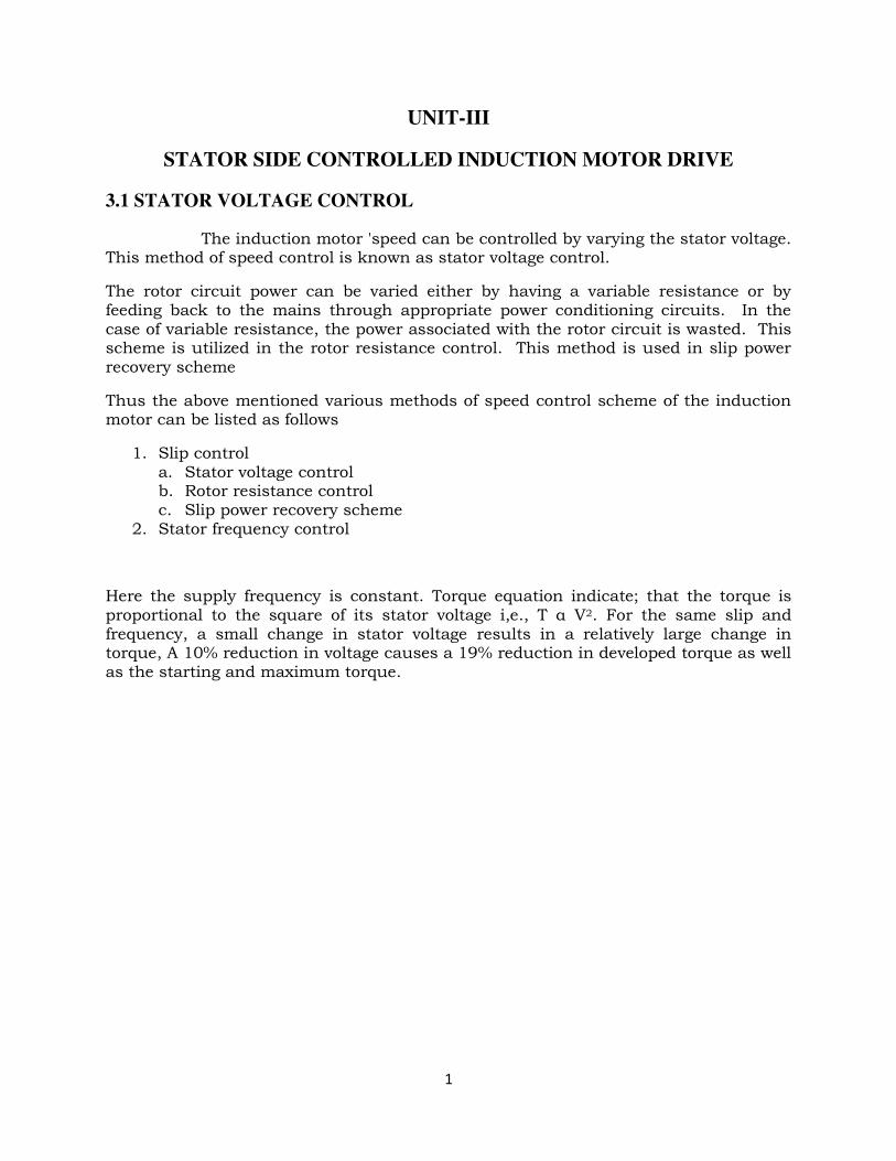
Fig (3.1 ) speed –Torque Characteristics of Stator voltage control
Figure shows speed torque characteristics of induction motor under stator voltage control. This characteristic is based on the torque equation. This shows two curves for two different values of the' stator voltage. Here the slip at the maximum torque remains unchanged since it is not a function of voltage. For a low slip motor, the speed range is very narrow. So this method is not used for wide range of speed control and constant torque load. This is applicable for requiring low starting torque and a narrow speed range at relatively low slip.
lf the stator copper loss and the friction, windage and core losses are neglected, from equation, the motor efficiency is given by
ηm = Pm/ Pag = (1-S)
This equation, increasing the slip i.e very low speeds the motor efficiency is poor.
It is an excellent method for reducing starting current and increasing the efficiency during light load conditions. The starting current is reduced since it is directly proportional to the input voltage. The losses are decreased, mainly core losses, which are proportional to the square of the voltage. The terminal voltage cannot exceeds rated value to prevent the damage of the winding’s insulation. Thus, this method is only suitable for speed control below the rated speed.
1. Conventional Method 2. Solid State control Method
3
3.2 Conventional method
The stator voltage can be controlled by two methods
1. Using auto transformer 2. Primary resistors connected in series with stator winding.
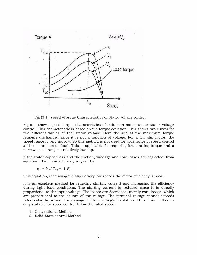
Fig (3.2.1) Conventional method using auto Transformer
The speed of the induction motor can be controlled by using auto transfomer. It is shown in figure . The input to the auto transformer is a fixed ac voltage .
By varying the auto transformer we can get variable ac output voltage without change in supply frequency. The variable voltage is fed to the induction motor. Then the induction motor speed also changes.
4
Primary resistor connected in series with stator winding
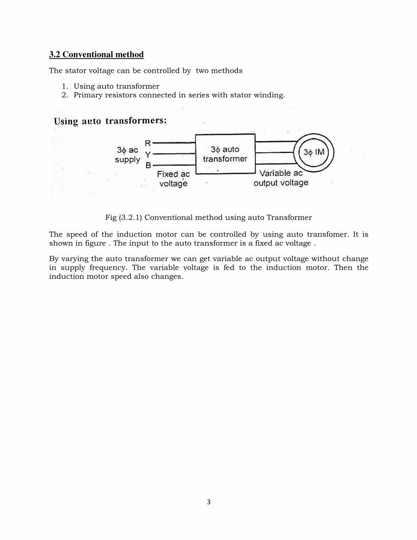
Fig (3.2.2) Primary resistor connected in series with stator winding
The primary resistors are connected in series with stator windings as shown in figure, By varying the primary resistance, the voltage drop across the motor terminals is reduced. That is, reduced voltage is fed to the motor. Then the motor speed can be reduced. lt is one method of conventional speed control of induction motor, The control method is very simple. The main disadvantage is that more power loss occurs in the primary resistors
3.3 AC voltage controller for 3-phase induction Motor
The stator voltage is controlled in these speed control systems by means of a power electronic controller. There are two methods of control as follows
(a) on-off control
(b) phase control.
5
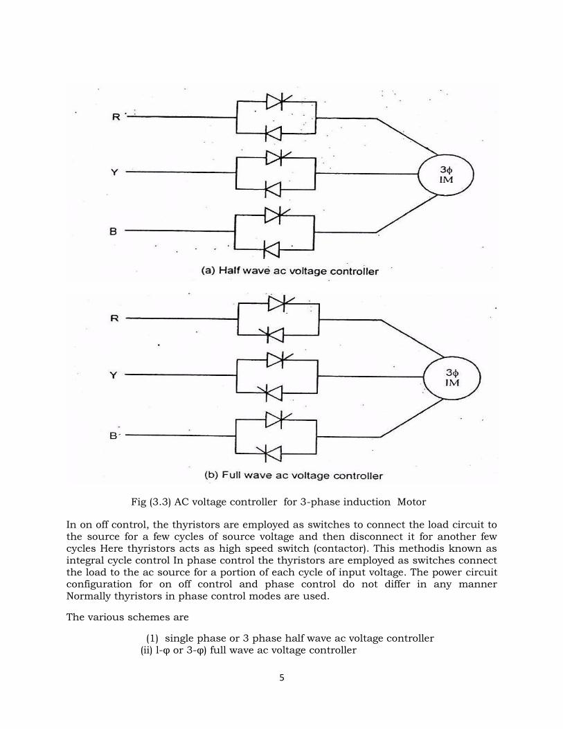
Fig (3.3) AC voltage controller for 3-phase induction Motor
In on off control, the thyristors are employed as switches to connect the load circuit to the source for a few cycles of source voltage and then disconnect it for another few cycles Here thyristors acts as high speed switch (contactor). This methodis known as integral cycle control In phase control the thyristors are employed as switches connect the load to the ac source for a portion of each cycle of input voltage. The power circuit configuration for on off control and phase control do not differ in any manner Normally thyristors in phase control modes are used.
The various schemes are
(1) single phase or 3 phase half wave ac voltage controller (ii) l-φ or 3-φ) full wave ac voltage controller
6
Figure (a) and (b) shows the circuits of three phase half wave and full wave ac voltage controllers for star connected stators. In half wave ac 'voltage controller consists of 3 SCRs and 3 diodes Here one SCR and one diode in antiparallel are connected between the line and motor in a phase., The full wave ac voltage controller consists of 6 SCRs Here two SCRs in antiparallel are connected_ between die line and motor in a phase The main advantage of half wave controller is a 'saving the cost of system The disadvantage is that it introduces more harmonics into the line current. The effective load voltage in three phase ac circuit can be varied by varying the thyristor tiring angles.
Advantages of stator voltage control
1.The control circuit is very simple
2. More compact and less weight
3. lts response time is quick
4. There is a considerable savings in energy and thus it is a economical method
Disadvantages
1. The input power factor is very low.
2. Voltage and current waveforms are highly distorted due to harmonics, which
affects the efficiency of the machine.
3. Performance is poor under running condition at low speed
4. Operating efficiency is low as resistance losses are high.
5. Maximum torque available from the motor decreases with decreases in stator
voltage. 6. At low speeds, motor currents are excessive and special arrangements should be provided to limit the excessive currents.
Applications
1. They are mainly used in low power applications such as fans, blowers and centrifugal pumps, where the starting torque is low.
2. They are also used for starting high power induction motors to limit the in-rush
current.
7
3.4 CLOSED LOOP CONTROL OF ELECTRIC DRIVE
Feedback loops in an electrical drive may be provided to satisfy one or more of the following
requirements,
1. Protection
2. Improvement of speed response
3. To improve steady state accuracy
Closed loop speed control
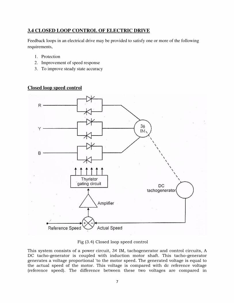
Fig (3.4) Closed loop speed control
This system consists of a power circuit, 3¢ IM, tachogenerator and control circuits, A DC tacho-generator is coupled with induction motor shaft. This tacho-generator generates a voltage proportional 'to the motor speed. The generated voltage is equal to the actual speed of the motor. This voltage is compared with dc reference voltage (reference speed). The difference between these two voltages are compared in
8
comparator and output voltage is error signal voltage. This voltage is amplified by amplifier and fed to the thyristor gating circuits. This controls the thyristor tiring angles and thereby changes the terminal voltage and hence the motor speed changes.
If the reference speed is greater than actual speed, the conduction periods of the SCRs are increased. The increased stator voltage allows the development of an increased motor torque and hence the motor speed also increases, lf the actual speed is greater than the reference speed, the conduction angle of SCRS are reduced and the motor torque decreases as well as reduces the motor speed. When the motor speed is equal to the reference speed, the conduction angles are just sufficient to allow the development of a motor torque.
This motor torque is equal to the load torque. In a high-gain feedback system the desired speed can be maintained and there is no necessity for the motor to have a flat speed-torque characteristics, since the output speed is determined by the reference (desired) signal rather than the open-loop characteristics of the motor. The stable operation may be obtained at any point of the induction motor speed-torque characteristic.
3.5 STATOR FREQUENCY CONTROL
The stator frequency control is the one of the speed control of 3 phase induction motors. Here we can vary the input frequency of the motor. Under steady state condition, the induction motor operates in the small-slip region, where the speed of the induction motor is always close to the synchronous speed of the rotating flux
The synchronous speed of the induction motor is given by
Ns = 120f / P
Where
f- Frequency of the supply voltage
P – Number of poles
In this equation, synchronous speed of the motor is directly proportional to the frequency of the supply voltage. Here, the supply frequency is changes, the motor speed also changes. Since the emf V1 induced in the stator winding of the induction motor is equal to
V1 = 4.44fφTphKw
Φ – flux /pole
Kw- winding factor
f- frequency of stator (input) supply
Tph – Number of turns in the stator winding
9
lf the frequency of the stator supply IS changes the magnitude of V1 should
also be changed to maintain the same value of flux .Here we consider two cases
1) Low frequency operation at constant voltage
2) High frequency operation at constant voltage
3.6 Low frequency operation at constant voltage
By decreasing the supply frequency at constant voltage V1, the value of air gap flux lncreases and the induction motor magnetic circuits also gets saturated For considering the emf equatlon,
V1 constant ; f decreases; φ increases
Due to this low frequency operation the following effects are given below
l) It draws more magnetizing current
2) Line currents and line voltages are distorted .Increase the core loss and stator copper loss .produce a high pitch acoustic noise.
3) Very low efficiency.
3.7 High frequency operation at constant voltage (field weakening mode)
With the constant input voltage,if the stator frequency is increased ,the motor speed also increases.Due to increase in frequency,flux and torque are reduces.
V1 constant ; f increases; φ decreases
By increasing the supply frequency of the motor ,the following effects are given below,
1. The no load speed increases 2. The maximum torque decreases 3. Starting torque reduces 4. Starting current decreases
The base speed ωb is defined as the synchronous speed corresponding to the rated frequency.The synchronous speed at any other frequency is equal to ωs = K ωb
10
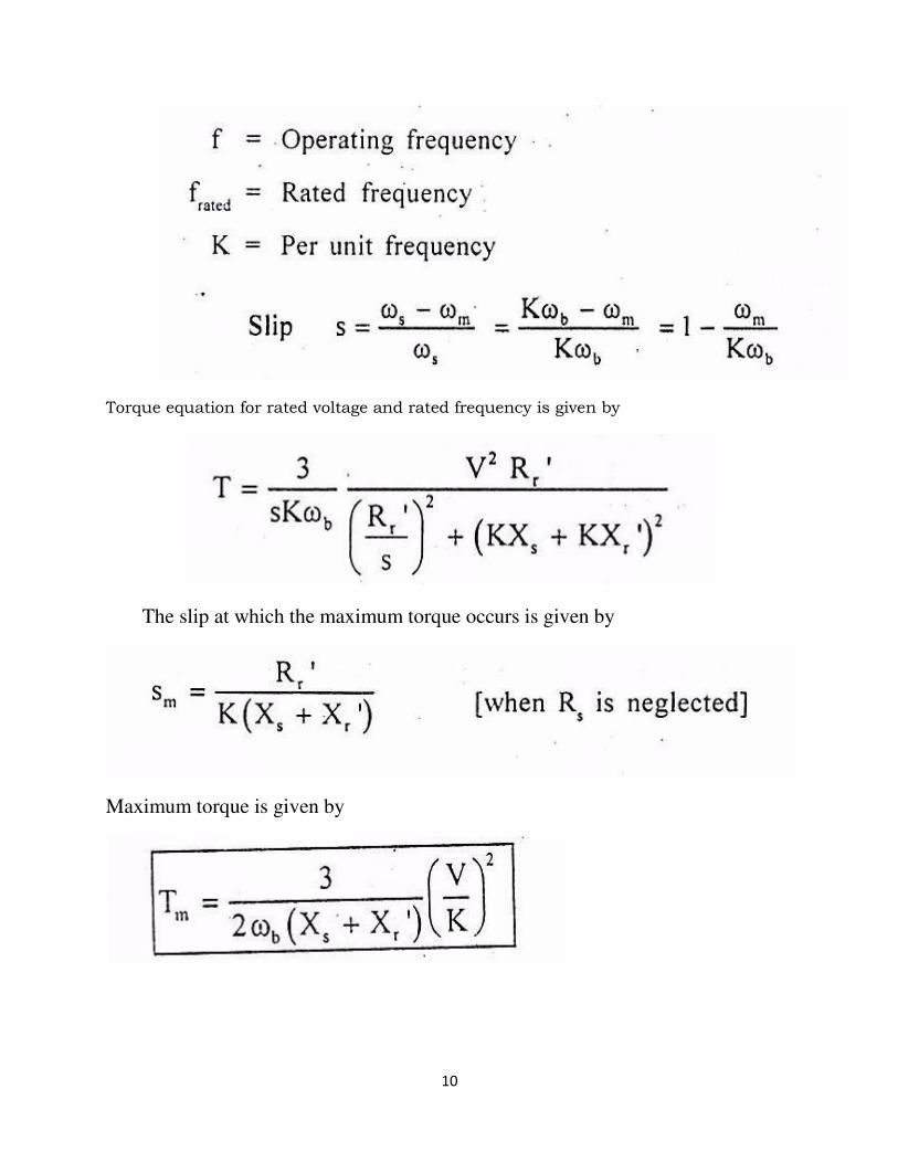
Torque equation for rated voltage and rated frequency is given by
The slip at which the maximum torque occurs is given by
Maximum torque is given by
11
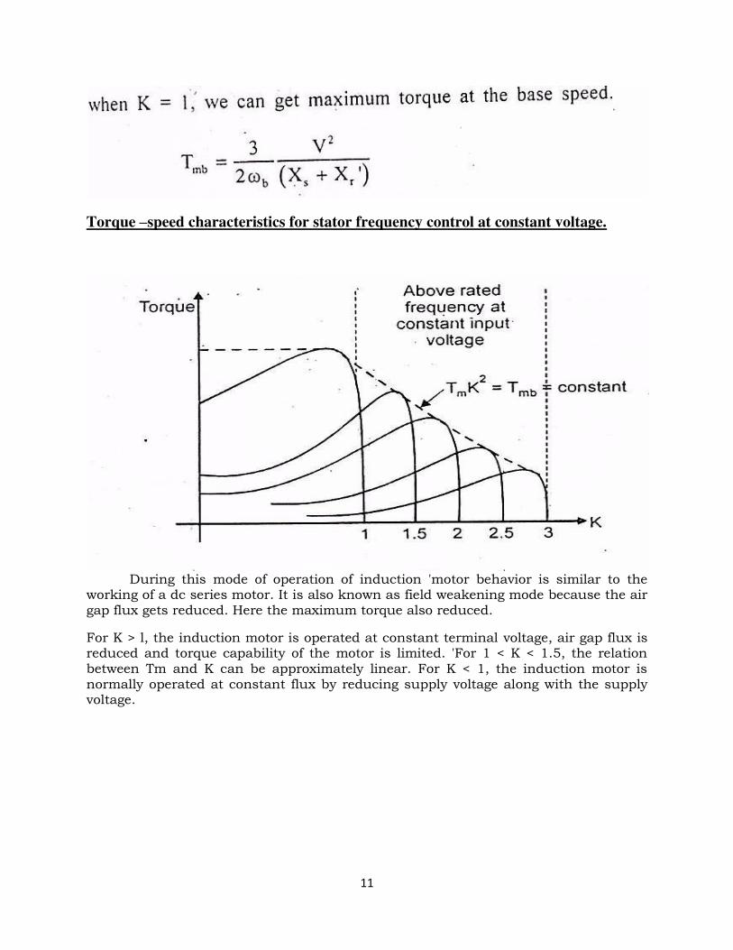
Torque –speed characteristics for stator frequency control at constant voltage.
During this mode of operation of induction 'motor behavior is similar to the working of a dc series motor. It is also known as field weakening mode because the air gap flux gets reduced. Here the maximum torque also reduced.
For K > l, the induction motor is operated at constant terminal voltage, air gap flux is reduced and torque capability of the motor is limited. 'For 1 < K < 1.5, the relation between Tm and K can be approximately linear. For K < 1, the induction motor is normally operated at constant flux by reducing supply voltage along with the supply voltage.
12
3.8 VARIABLE FREQUENCY AC MOTOR DRIVES
The induction motor speed can be controlled by varying the supply frequency This method is mainly applied to the squirrel cage induction motor. The variable frequency control allows good running and transient performance to be obtained from a squirrel cage induction motor.
The variable frequency induction motor drives are very popularly because of
i) Special applications requiring maintenance free operation, such as under ground and under water installations.
ii) Applications involving explosive and contaminated environments such as in mines and the chemical industry.
The variable frequency AC drives applications are in
I) Pumps 2) Fans 3) Mill run out tables
4) Blowers 5) Compressors 6) Spindle drives
7) Conveyors 8) Machine tools and so on
Due to availability of power semiconductor devices such as power transistors, power MOSFETs, IGBTS and GTOs with improved ratings and characteristics, general purpose medium and high power variable frequency drives are available. The cost of the equipment is less compared to the drives. The variable frequency conversion can be made by using,
1. Voltage source inverter 2. Current source inverter 3. Cycloconverter
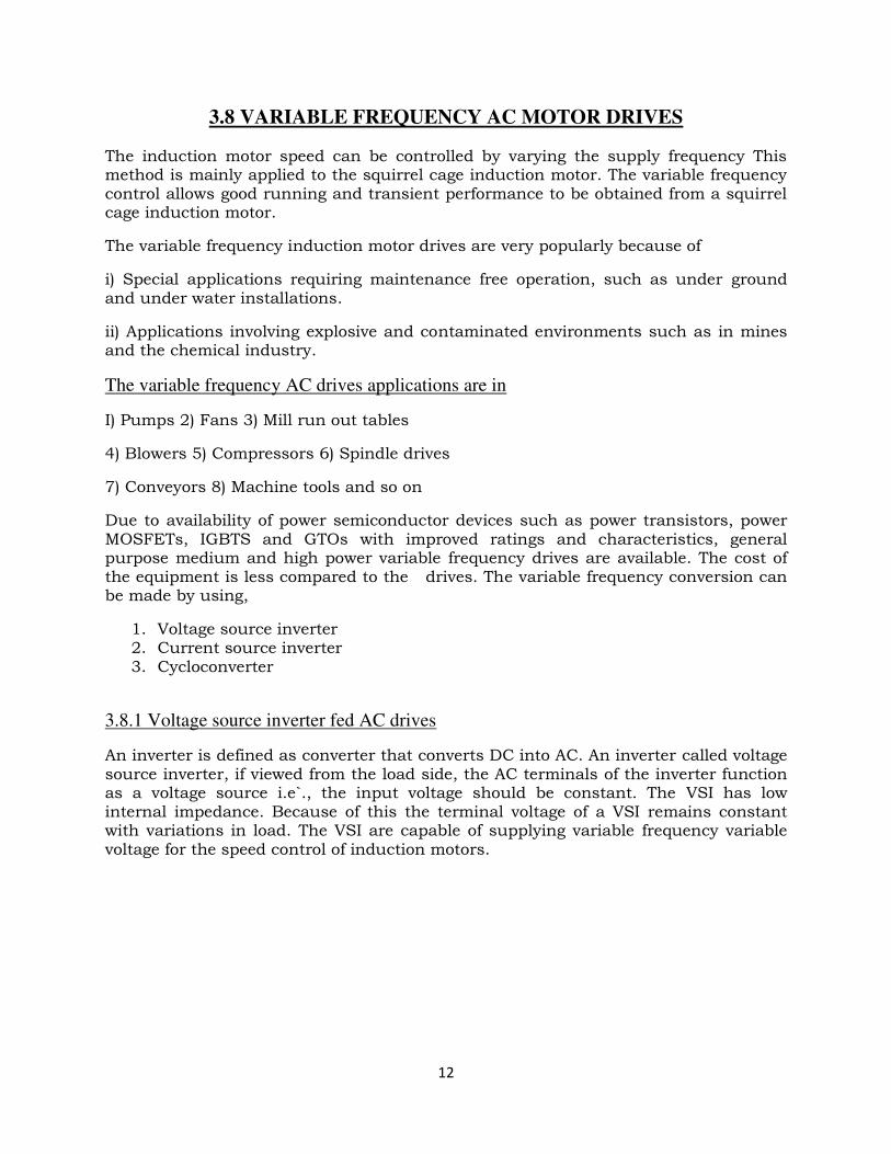
3.8.1 Voltage source inverter fed AC drives
An inverter is defined as converter that converts DC into AC. An inverter called voltage source inverter, if viewed from the load side, the AC terminals of the inverter function as a voltage source i.e`., the input voltage should be constant. The VSI has low internal impedance. Because of this the terminal voltage of a VSI remains constant with variations in load. The VSI are capable of supplying variable frequency variable voltage for the speed control of induction motors.
13
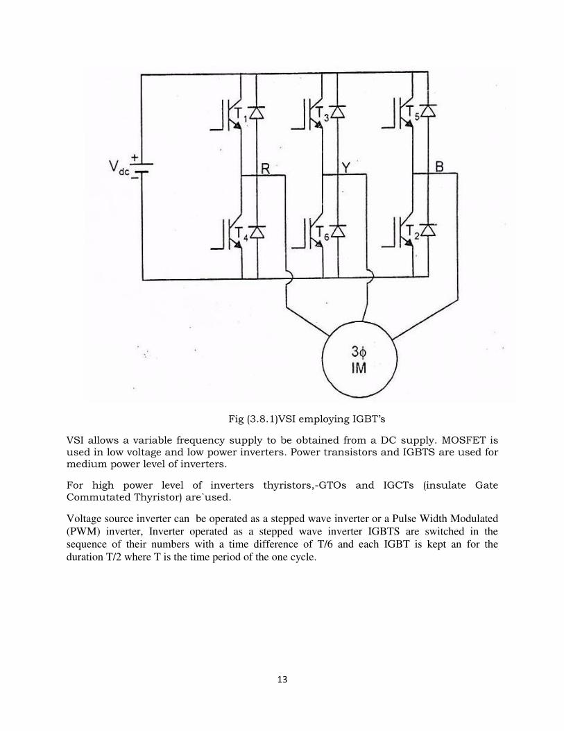
Fig (3.8.1)VSI employing IGBT’s
VSI allows a variable frequency supply to be obtained from a DC supply. MOSFET is used in low voltage and low power inverters. Power transistors and IGBTS are used for medium power level of inverters.
For high power level of inverters thyristors,-GTOs and IGCTs (insulate Gate Commutated Thyristor) are`used.
Voltage source inverter can be operated as a stepped wave inverter or a Pulse Width Modulated
(PWM) inverter, Inverter operated as a stepped wave inverter IGBTS are switched in the
sequence of their numbers with a time difference of T/6 and each IGBT is kept an for the
duration T/2 where T is the time period of the one cycle.
14
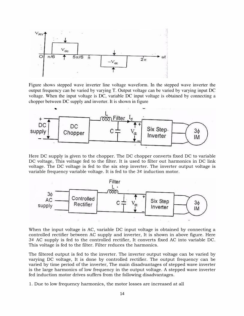
Figure shows stepped wave inverter line voltage waveform. In the stepped wave inverter the
output frequency can be varied by varying T. Output voltage can be varied by varying input DC
voltage. When the input voltage is DC, variable DC input voltage is obtained by connecting a
chopper between DC supply and inverter. It is shown in figure
Here DC supply is given to the chopper. The DC chopper converts fixed DC to variable DC voltage, This voltage fed to the filter. It is used to filter out harmonics in DC link voltage. The DC voltage is fed to the six step inverter. The inverter output voltage is variable frequency variable voltage. It is fed to the 3¢ induction motor.
When the input voltage is AC, variable DC input voltage is obtained by connecting a controlled rectifier between AC supply and inverter, It is shown in above figure. Here 3¢ AC supply is fed to the controlled rectifier, It converts fixed AC into variable DC. This voltage is fed to the filter. Filter reduces the harmonics.
The filtered output is fed to the inverter. The inverter output voltage can be varied by varying DC voltage, It is done by controlled rectifier. The output frequency can be varied by time period of the inverter, The main disadvantages of stepped wave inverter is the large harmonics of low frequency in the output voltage. A stepped wave inverter fed induction motor drives suffers from the following disadvantages.
1. Due to low frequency harmonics, the motor losses are increased at all
15
speeds causing derating of the motor.
2. Motor produces pulsating torques because of fifth, seventh, eleventh and
thirteenth harmonics which cause jerky motion of the rotor at low speeds.
3. Harmonic content in an induction motor current increases at low speeds. The
machine saturates at low speeds due to high (V/f) ratio. These two effects
overheat the motor at low speeds, thus limiting lowest speed to around 40%
of base speed.
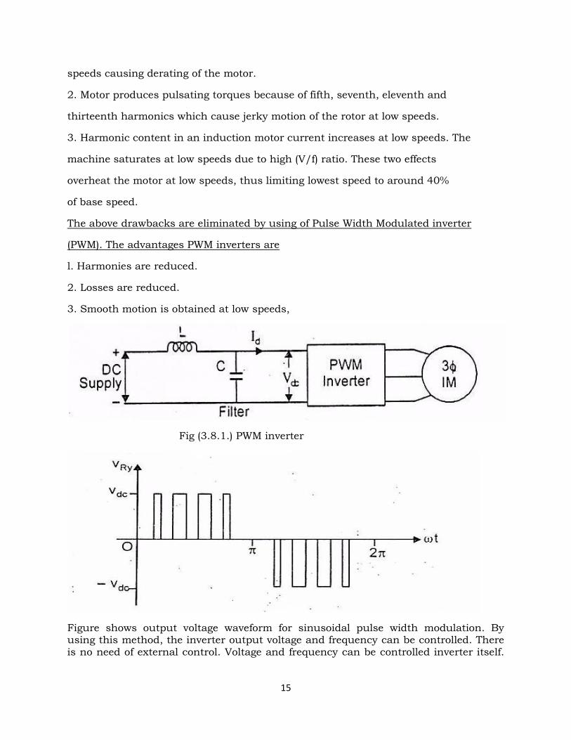
The above drawbacks are eliminated by using of Pulse Width Modulated inverter
(PWM). The advantages PWM inverters are
l. Harmonies are reduced.
2. Losses are reduced.
3. Smooth motion is obtained at low speeds,
Fig (3.8.1.) PWM inverter
Figure shows output voltage waveform for sinusoidal pulse width modulation. By using this method, the inverter output voltage and frequency can be controlled. There is no need of external control. Voltage and frequency can be controlled inverter itself.
16
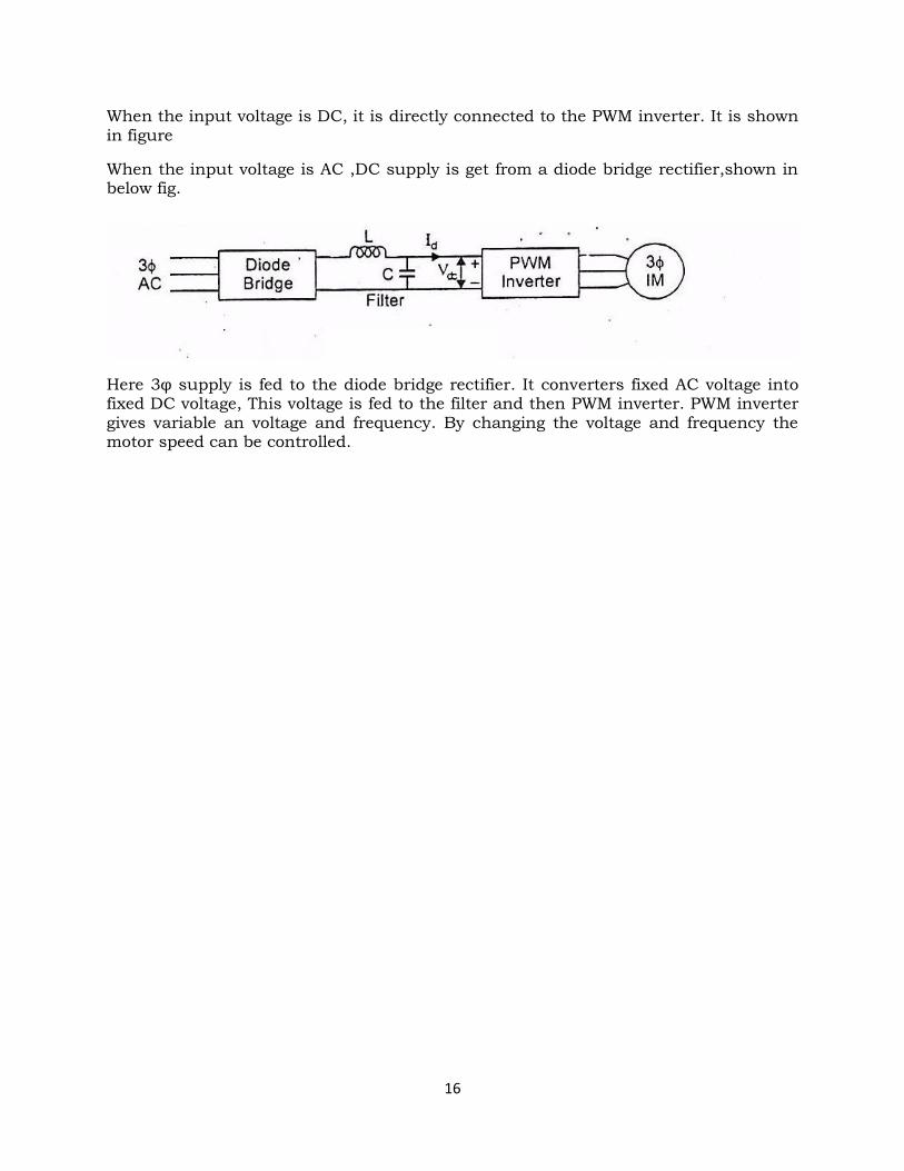
When the input voltage is DC, it is directly connected to the PWM inverter. It is shown in figure
When the input voltage is AC ,DC supply is get from a diode bridge rectifier,shown in below fig.
Here 3φ supply is fed to the diode bridge rectifier. It converters fixed AC voltage into fixed DC voltage, This voltage is fed to the filter and then PWM inverter. PWM inverter gives variable an voltage and frequency. By changing the voltage and frequency the motor speed can be controlled.
Related Documents