UNIT III PROJECTION OF POINTS, LINES AND PLANE SURFACES Projection of points and straight lines located in the first quadrant – Determination of true lengths and true inclinations – Projection of polygonal surface and circular Lamina inclined to both reference planes. What is Projection? A projection is defined as a view imagined on to a plane known as projection plane. In graphic language shape of an object is described by projection, which is image of the object, formed by the rays of sight taken in some particular direction from the object into a picture plane. Depending upon the orientation of the object, location of the point of sight and the direction of lines of sight relative to the picture plane, different types of projections such as orthographic, isometric, perspective, oblique etc. can be obtained. The point, from which the observer is assumed to view the object, is called station point or the center of projection and the lines of rays drawn from the object to the plane are called projectors. Methods of Projection There are four methods of projections commonly used 1. Orthographic projection 2. Isometric projection 3. Oblique projection 4. Perspective projection. Let us discuss small introduction of each one of these so that we can understand examples 1. Orthographic projection-when the projectors are perpendicular to the plane of projection the projection is known as orthographic projection. 2. Isometric projection-when the projectors are parallel but inclined to one plane of projection, the projection thus obtained is known as isometric projection 3. Oblique projection-when the projectors are parallel to each other and oblique to the plane of projection, the projection drawn is known as oblique projection. 4. Perspective projection-when the projectors converge to a point, the projection thus obtained is known as perspective projection

Welcome message from author
This document is posted to help you gain knowledge. Please leave a comment to let me know what you think about it! Share it to your friends and learn new things together.
Transcript
UNIT III PROJECTION OF POINTS, LINES AND PLANE SURFACES
Projection of points and straight lines located in the first quadrant – Determination
of true lengths and true inclinations – Projection of polygonal surface and circular
Lamina inclined to both reference planes.
What is Projection?
A projection is defined as a view imagined on to a plane known as projection plane. In graphic language shape of an object is described by projection, which is image of the object, formed by the rays of sight taken in some particular direction from the object into a picture plane. Depending upon the orientation of the object, location of the point of sight and the direction of lines of sight relative to the picture plane, different types of projections such as orthographic, isometric, perspective, oblique etc. can be obtained. The point, from which the observer is assumed to view the object, is called station point or the center of projection and the lines of rays drawn from the object to the plane are called projectors.
Methods of Projection
There are four methods of projections commonly used
1. Orthographic projection
2. Isometric projection
3. Oblique projection
4. Perspective projection.
Let us discuss small introduction of each one of these so that we can understand examples 1. Orthographic projection-when the projectors are perpendicular to the plane of
projection the projection is known as orthographic projection.
2. Isometric projection-when the projectors are parallel but inclined to one plane
of projection, the projection thus obtained is known as isometric projection
3. Oblique projection-when the projectors are parallel to each other and oblique
to the plane of projection, the projection drawn is known as oblique projection.
4. Perspective projection-when the projectors converge to a point, the projection
thus obtained is known as perspective projection

Planes of References
In study of orthographic projection, two principle planes are used. They are known as coordinate planes. One plane is horizontal and the other vertical and they intersect each other at right angles. This can be drawn as you have seen the planes divide themselves into four angular spaces or dihedral angles. The horizontal plane is known as H.P and the vertical plane is known as V.P.Their line of intersection is known as the ground line denoted by the line XY.The projection of an object on H.P is known as the plan and the projection on the V.P is known as elevation.
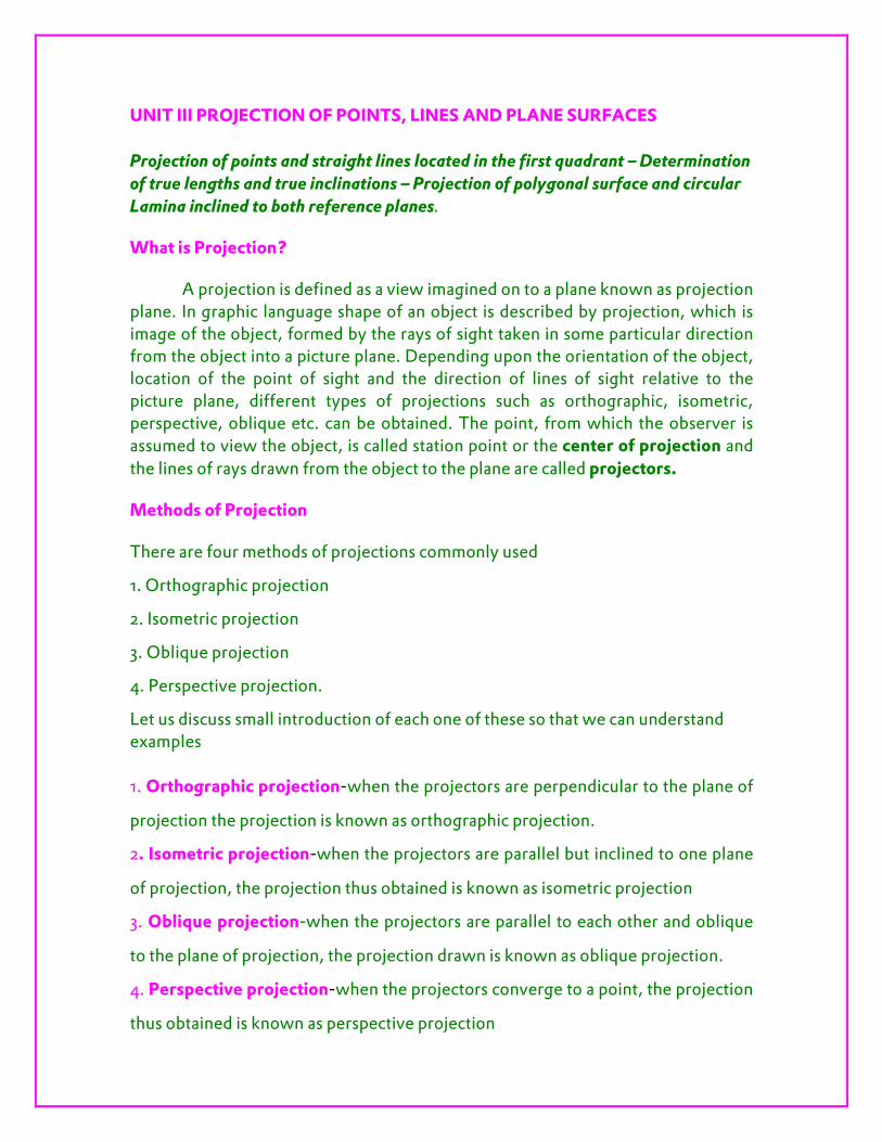
Orthographic Projection
While projecting any object on a plane if the rays of sight are taken perpendicular to the plane of projection, the projection method is then called orthographic projection. In this method the observer is assumed to be at infinite distance from the plane of projection, such that the projectors will be parallel to each other.
Orthographic Projection
While projecting any object on a plane if the rays of sight are taken
perpendicular to the plane of projection, the projection method is then called
orthographic projection. In this method the observer is assumed to be at infinite
distance from the plane of projection, such that the projectors will be parallel to
each other.
Here the figure shows the two principal planes H.P and V.P and another auxiliary vertical plane (AVP). AVP is perpendicular to both V.P and H.P. Front view is drawn by projecting the object on the V.P and top view is drawn by projecting on the H.P the projection on the AVP as seen from the left of the object and drawn on the right hand of the front view, is called left side view. To draw side view rotate the AVP in the direction of arrow shown, so as to make it coincide with the V.P. looking the object from the left, the left side view is obtained and drawn on the right of the front view. There are two systems by which an object can be represented. a. First angle projection
b. Third angle projection
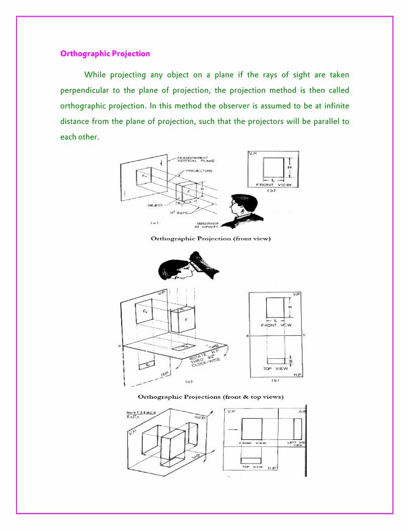
Both these are named according to the quadrant in which the object is imagined to be placed for purposes of projection of projection. As far as the shape and sizes of views are concerned there is no difference between these two systems. The only difference lies in the relative positions of the various views. Principle of First Angle Projection
When the object is situated in first quadrant that is in front of V.P and H.P, the object lies in between the observer and the plane of projection. In this case the object is to be transparent and the projectors are imagined to be extended from various points of the object to meet the projection plane. The meeting points when join in order form an image. This is the principle of first angle projection.

Principle of Third Angle Projection
When the object is situated in third quadrant that is in front of V.P and below H.P, the projection plane lies between the observer and the object. This means that the plane of projection is said to be transparent. The intersection of this plane with the projectors from all the points of object would form an image on the transparent plane. This is the principle of third angle projection.

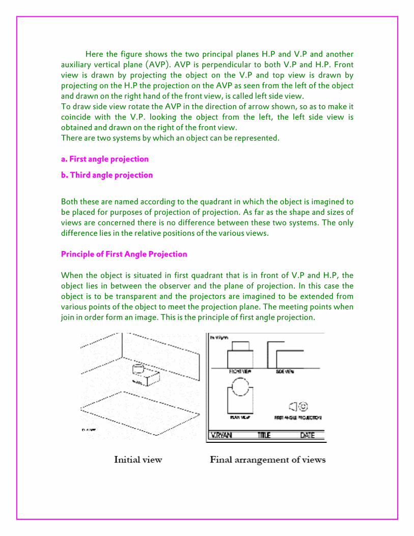
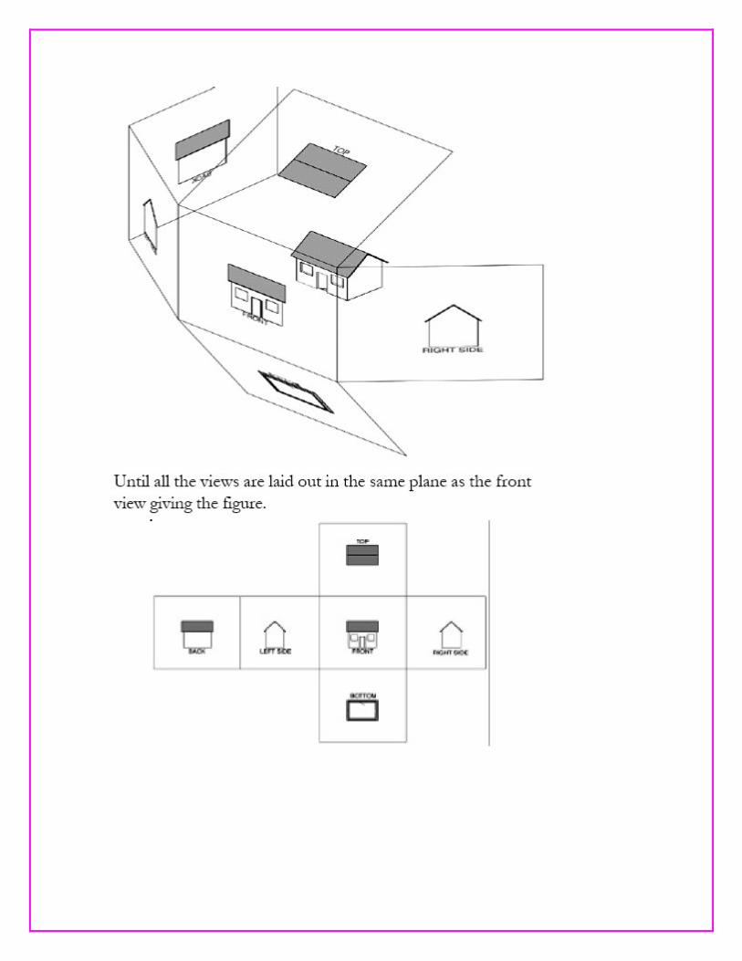
Making Orthographic Views
Representation drawing and sketching is concerned with what you see or drawing which you imagine as if you actually saw it. For making orthographic views we can consider an object enclosed in an imaginary glass box, positioned such that the planes of glass are parallel to the major surfaces of the object and 90 degrees to each other.
If one projects lines from the corners of the object (with each line at 90 degrees to a surface of the glass), until these lines intersect the glass, one lay out 6 views each of which represents the object as it is seen by the various planes of glass.

Projection of points:
Points in Space
A Point may lie in space, in any one of the four quadrants, formed by the two references planes of projections, namely, H.P and V.P. see figure 8.4, showing the four quadrants formed by H.P. and V.P.
Positions of a Point
• When a point lies in the first quadrants, it will be above H.P. and in front of
V.P.
• When the point lies in the second quadrant, it will be above H.P. and behind
V.P.
• When the point lies in the third quadrant, it will be below H.P. and behind
V.P.
• When the point lies in the fourth quadrant, it will be in front of V.P. and
below H.P.
After knowing the distances of a point from H.P. and V.P., projections on H.P. and V.P are found by extending the projectors perpendicular to both the planes. Projection on H.P. is called Top View and Projection on V.P. is called Front View.
System of Notation
1. In this text, the actual points in space are denoted by capital letters A, B, C etc.
2. Their front view are denoted by their corresponding lower case letters with
dashes a’, b’, c’, etc., and their top view by the lower case letters a, b, c etc.
3. Projectors are always drawn as continuous thin lines (2H pencil)

Projection of a Point in the First Quadrant
Problem 1: Point A is 20mm above H.P. and 30mm in front of V.P. Draw its front
view and top view.
1. Look at the pictorial view. The point A lies in the first quadrant.
2. To Obtain the front view a’, look from the front: Point A is 20mm above H.P.
Aa’ is the projection perpendicular to V.P. Hence a’ is the front view if the point A
and it is 20mm above the XY line.
3. To obtain the top view, look from the top: Point A is 30mm in front of V.P. Aa is
the projector perpendicular to H.P. Hence a is the top view of the point A and it is
30mm in front of XY.
4. To convert the projections a’ and a obtained in the pictorial view into orthographic projections: Rotate the H.P. about the XY line through 900 in the CW direction as shown in fig. (i). after rotation, the first quadrant is opened out and the H.P. occupies the position (dotted lines) vertically below the V.P. Also, the
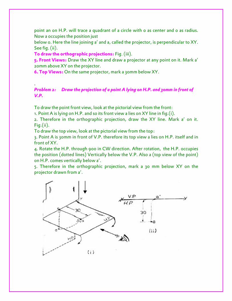
point an on H.P. will trace a quadrant of a circle with o as center and o as radius. Now a occupies the position just below o. Here the line joining a’ and a, called the projector, is perpendicular to XY. See fig. (ii). To draw the orthographic projections: Fig. (iii). 5. Front Views: Draw the XY line and draw a projector at any point on it. Mark a’ 20mm above XY on the projector. 6. Top Views: On the same projector, mark a 30mm below XY. . Problem 2: Draw the projection of a point A lying on H.P. and 30mm in front of
V.P.
To draw the point front view, look at the pictorial view from the front: 1. Point A is lying on H.P. and so its front view a lies on XY line in fig.(i). 2. Therefore in the orthographic projection, draw the XY line. Mark a’ on it. Fig.(ii). To draw the top view, look at the pictorial view from the top: 3. Point A is 30mm in front of V.P. therefore its top view a lies on H.P. itself and in front of XY. 4. Rotate the H.P. through 900 in CW direction. After rotation, the H.P. occupies the position (dotted lines) Vertically below the V.P. Also a (top view of the point) on H.P. comes vertically below a’. 5. Therefore in the orthographic projection, mark a 30 mm below XY on the projector drawn from a’.
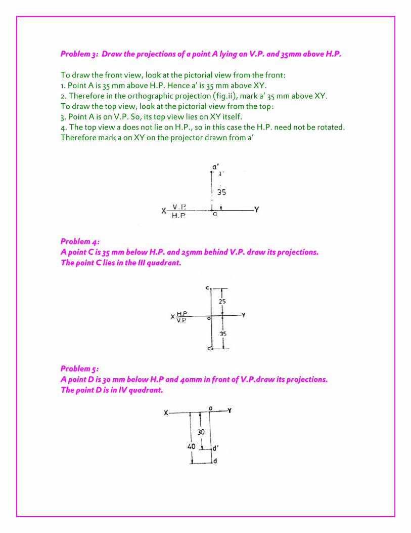
Problem 3: Draw the projections of a point A lying on V.P. and 35mm above H.P.
To draw the front view, look at the pictorial view from the front: 1. Point A is 35 mm above H.P. Hence a’ is 35 mm above XY. 2. Therefore in the orthographic projection (fig.ii), mark a’ 35 mm above XY. To draw the top view, look at the pictorial view from the top: 3. Point A is on V.P. So, its top view lies on XY itself. 4. The top view a does not lie on H.P., so in this case the H.P. need not be rotated. Therefore mark a on XY on the projector drawn from a’
Problem 4:
A point C is 35 mm below H.P. and 25mm behind V.P. draw its projections.
The point C lies in the III quadrant.
Problem 5:
A point D is 30 mm below H.P and 40mm in front of V.P.draw its projections.
The point D is in lV quadrant.

Projection of Straight Lines Introduction
A straight line is the shortest distance between two points. Hence, the projections f a straight line may be drawn by joining the respective projections of its ends, which are points. The position of a straight line may also be described with respect to the two reference planes. It may be 1. Parallel to one or both the planes.
2. Contained by one or both the planes.
3. Perpendicular to one of the planes.
4. Inclined to one plane and parallel to the other.
5. Inclined to both the planes.
6. Projections of lines inclined to both the planes.
7. Line contained by a plane perpendicular to both the reference planes.
8. True length of a straight line and its inclinations with the reference planes.
9. Traces of a line.
10. Methods of determining traces of a line.
11. Traces of a line, the projections of which are perpendicular to xy.
12. Positions of traces of a line.
Line parallel to one or both the planes:
a. Line AB is parallel to the H.P.
a and b are the top views of the ends A and B respectively. The line joining a and b is the top view of AB. It can be clearly seen that the figure Abba is a rectangle. Hence, the top view ab is equal to AB. a’ b’ is the front view of AB and a parallel to xy.
b. Line CD is parallel to the V.P.
The line c’d’ is the front view and is equal to CD; the top view cd is parallel to xy. c. Line EF is parallel to the H.P. and the V.P.
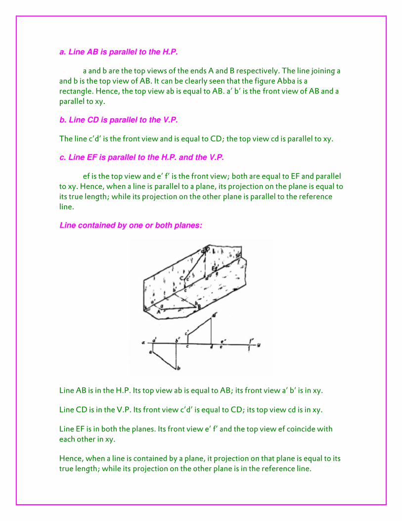
ef is the top view and e’ f’ is the front view; both are equal to EF and parallel to xy. Hence, when a line is parallel to a plane, its projection on the plane is equal to its true length; while its projection on the other plane is parallel to the reference line. Line contained by one or both planes:
Line AB is in the H.P. Its top view ab is equal to AB; its front view a’ b’ is in xy.
Line CD is in the V.P. Its front view c’d’ is equal to CD; its top view cd is in xy.
Line EF is in both the planes. Its front view e’ f’ and the top view ef coincide with each other in xy.
Hence, when a line is contained by a plane, it projection on that plane is equal to its true length; while its projection on the other plane is in the reference line.
Line perpendicular to one of the planes:
When a line is perpendicular to one reference plane, it will be parallel to the other.
In first-angle projection method, when top views of two or more points coincide, the point which is comparatively farther away from xy in the front view will be visible; and when their front views coincide, that which is farther away from xy in the top view will be visible. Line inclined to one plane and parallel to the other:
The inclination of a line to a plane is the angle, which the line makes with its projection on that plane.
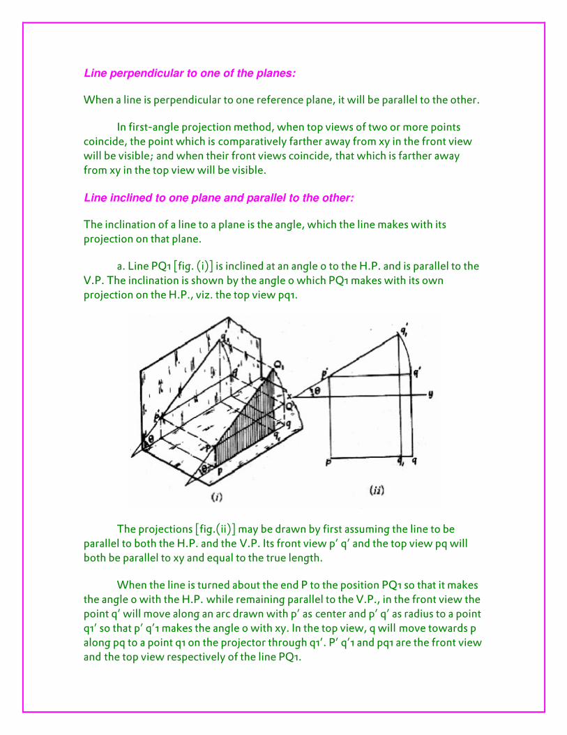
a. Line PQ1 [fig. (i)] is inclined at an angle 0 to the H.P. and is parallel to the V.P. The inclination is shown by the angle 0 which PQ1 makes with its own projection on the H.P., viz. the top view pq1.
The projections [fig.(ii)] may be drawn by first assuming the line to be parallel to both the H.P. and the V.P. Its front view p’ q’ and the top view pq will both be parallel to xy and equal to the true length.
When the line is turned about the end P to the position PQ1 so that it makes the angle 0 with the H.P. while remaining parallel to the V.P., in the front view the point q’ will move along an arc drawn with p’ as center and p’ q’ as radius to a point q1’ so that p’ q’1 makes the angle 0 with xy. In the top view, q will move towards p along pq to a point q1 on the projector through q1’. P’ q’1 and pq1 are the front view and the top view respectively of the line PQ1.
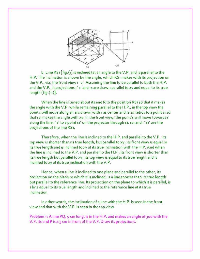
b. Line RS1 [fig.(i) is inclined tat an angle to the V.P. and is parallel to the
H.P. The inclination is shown by the angle, which RS1 makes with its projection on the V.P., viz. the front view r’ s1. Assuming the line to be parallel to both the H.P. and the V.P., it projections r’ s’ and rs are drawn parallel to xy and equal to its true length (fig.(ii)].
When the line is tuned about its end R to the position RS1 so that it makes the angle with the V.P. while remaining parallel to the H.P., in the top view the point s will move along an arc drawn with r as center and rs as radius to a point s1 so that rs1 makes the angle with xy. In the front view, the point’s will move towards r’ along the line r’ s’ to a point s1’ on the projector through s1. rs1 and r’ s1’ are the projections of the line RS1.
Therefore, when the line is inclined to the H.P. and parallel to the V.P., its top view is shorter than its true length, but parallel to xy; its front view is equal to its true length and is inclined to xy at its true inclination with the H.P. And when the line is inclined to the V.P. and parallel to the H.P., its front view is shorter than its true length but parallel to xy; its top view is equal to its true length and is inclined to xy at its true inclination with the V.P.
Hence, when a line is inclined to one plane and parallel to the other, its projection on the plane to which it is inclined, is a line shorter than its true length but parallel to the reference line. Its projection on the plane to which it is parallel, is a line equal to its true length and inclined to the reference line at its true
inclination.
In other words, the inclination of a line with the H.P. is seen in the front view and that with the V.P. is seen in the top view.
Problem 1: A line PQ, 9 cm long, is in the H.P. and makes an angle of 300 with the V.P. Its end P is 2.5 cm in front of the V.P. Draw its projections.
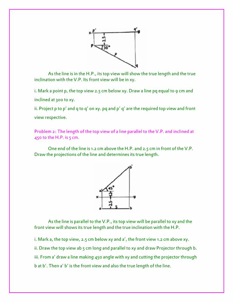
As the line is in the H.P., its top view will show the true length and the true
inclination with the V.P. Its front view will be in xy.
i. Mark a point p, the top view 2.5 cm below xy. Draw a line pq equal to 9 cm and
inclined at 300 to xy.
ii. Project p to p’ and q to q’ on xy. pq and p’ q’ are the required top view and front
view respective.
Problem 2: The length of the top view of a line parallel to the V.P. and inclined at 450 to the H.P. is 5 cm.
One end of the line is 1.2 cm above the H.P. and 2.5 cm in front of the V.P. Draw the projections of the line and determines its true length.
As the line is parallel to the V.P., its top view will be parallel to xy and the front view will shows its true length and the true inclination with the H.P. i. Mark a, the top view, 2.5 cm below xy and a’, the front view 1.2 cm above xy.
ii. Draw the top view ab 5 cm long and parallel to xy and draw Projector through b.
iii. From a’ draw a line making 450 angle with xy and cutting the projector through
b at b’. Then a’ b’ is the front view and also the true length of the line.

Problem 3: The front view of a 7.5 cm long line measures 5.5 cm. The line is parallel to the H.P. and one of its ends is in the V.P. and 2.5 cm above the H.P. Draw the projections of the line and determines its inclination with the V.P.
As the line is parallel to the H.P., its front view will be parallel to xy.
i. Mark a, the top view of one end in xy, and a’, its front view, 2.5 cm above xy.
ii. Draw the front view a’ b’, 5.5 cm long and parallel to xy. With a as center and
radius equal to 7.5 cm, draw an arc cutting the projector through b’ at b. Join a with
b. ab is the top view of the line. Its inclination with xy, viz. is the inclination of the
line with the V.P.
Line inclined to both the planes:
a. A line AB (fig) is inclined at 0 to the H.P. and is parallel to the V.P. The end A is in the H.P. AB is shown as the hypotenuse of a right-angled triangle, making the angle 0 with the base.
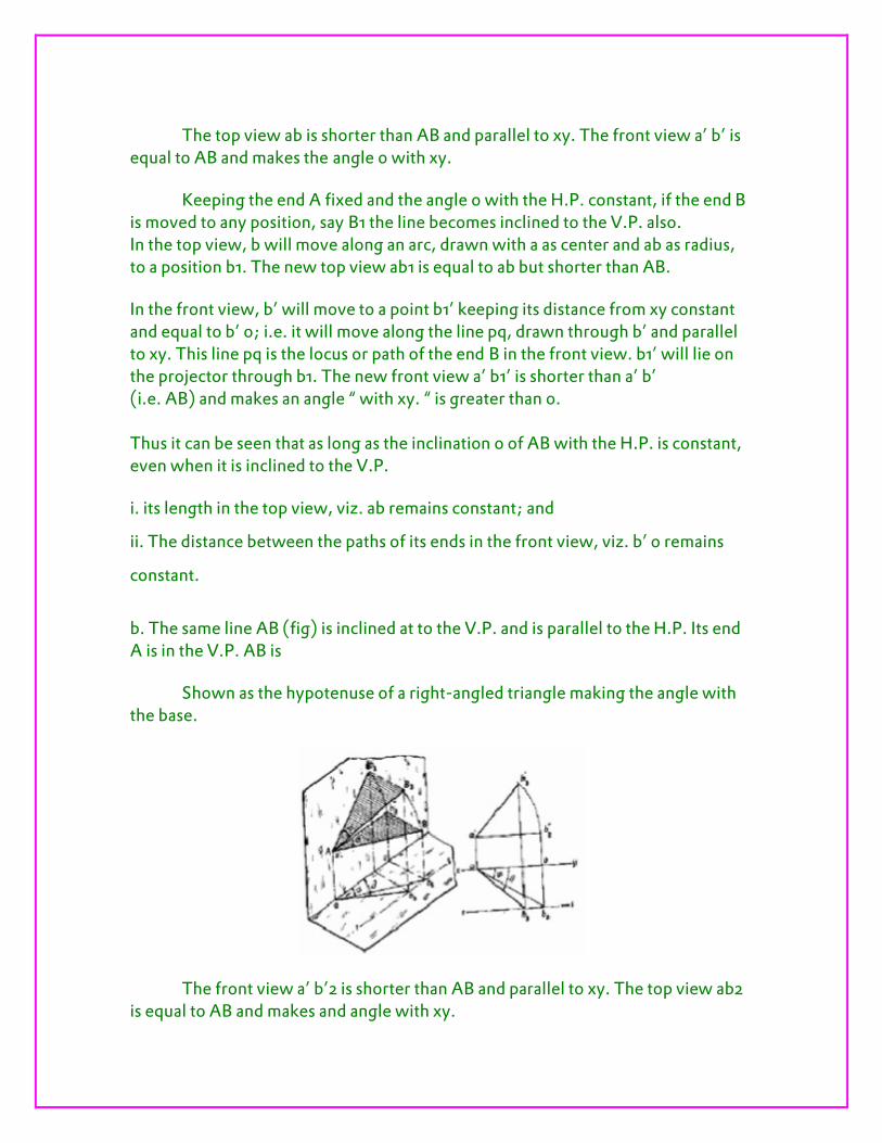
The top view ab is shorter than AB and parallel to xy. The front view a’ b’ is equal to AB and makes the angle 0 with xy.
Keeping the end A fixed and the angle 0 with the H.P. constant, if the end B is moved to any position, say B1 the line becomes inclined to the V.P. also. In the top view, b will move along an arc, drawn with a as center and ab as radius, to a position b1. The new top view ab1 is equal to ab but shorter than AB.
In the front view, b’ will move to a point b1’ keeping its distance from xy constant and equal to b’ o; i.e. it will move along the line pq, drawn through b’ and parallel to xy. This line pq is the locus or path of the end B in the front view. b1’ will lie on the projector through b1. The new front view a’ b1’ is shorter than a’ b’ (i.e. AB) and makes an angle “ with xy. “ is greater than 0. Thus it can be seen that as long as the inclination 0 of AB with the H.P. is constant, even when it is inclined to the V.P.
i. its length in the top view, viz. ab remains constant; and
ii. The distance between the paths of its ends in the front view, viz. b’ o remains
constant.
b. The same line AB (fig) is inclined at to the V.P. and is parallel to the H.P. Its end A is in the V.P. AB is
Shown as the hypotenuse of a right-angled triangle making the angle with the base.
The front view a’ b’2 is shorter than AB and parallel to xy. The top view ab2 is equal to AB and makes and angle with xy.
Keeping the end A fixed and the angle with the V.P. constant, if B is moved to any position, say B3, the line will become inclined to the H.P. also.
In front view, b2’ will move along the arc, drawn with a’ as center and a’ b2’ as radius, to a position b3’.The new front view a’ b3’ is equal to a’ b2’ but is shorter than AB.
In the top view, b2 will move to a point b3 along the line rs, drawn through b2 and parallel to xy, thus keeping its distance from the path of a, viz. b2 o constant. rs is the locus or path of the end B in the top view. The point b3 lies on the projector through b3’. The new top view ab3 is shorter than ab2 (i.e. AB) and makes an angle â with xy. â is greater than .
Here also we find that, as long as the inclination of AB with the V.P. does not change, even when it becomes inclined to the H.P.
i. its length in the front view, viz. a’ b2’ remains constant; and
ii. The distance between the paths of its ends in the top view, viz. b2 o remains
constant.
Hence, when a line is inclined to both the planes, its projections are shorter than the true length and inclined to xy at angles greater than the true inclinations. These angles viz. á and â are called apparent angles of inclination. Projections of lines inclined to both the planes:
From Art. (a) above, we find that as long as the inclination of AB with the H.P. is constant (i) its length in the top view, viz. ab remains constant, and (ii) in the front view, the distance between the loci of its ends, viz. b’ o remains constant.
In other words if (i) its length in the top view is equal to ab, and (ii) the distance between the paths of its ends in the front view is equal to b’ o, the inclination of AB with the H.P. will be equal to .
Similarly, from Art. (b) above, we find that as long as the inclination of AB with the V.P. is constant (i) its length in the front view, viz. a’ b2’ remains constant, and (ii) in the top view, the distance between the loci of its ends, viz. b2 o remains constant. The reverse of this is also true, viz. (i) if its length in the front view is equal to a’ b2’, and (ii) the distance between the paths of its ends in the top view is equal to b2 o,the inclination of AB with the V.P. will be equal to .

Combining the above two findings, we conclude that when AB is inclined at 0 to the H.P. and at to the V.P. (i) its lengths in the top view and the front view will be equal to ab and a’ b2’ respectively, and (ii) the distances between the paths of its ends in the front view and the top view will be equal to b’ o and b2 o
respectively. The two lengths when arranged with their ends in their respective paths and in projections with each other will be the projections of the line AB, as illustrated in the below problem.
Problem.4: Given the line AB, its inclinations 0 with the H.P. and with the V.P. and the position of one end A. Draw its projections.
Mark the front view a’ and the top view a according to the given position of A (fig).
Let us first determine the lengths of AB in the top view and the front view and the paths of its ends in the front view and the top view.
i. Assume AB to be parallel to the V.P. and inclined at 0 to the H.P. AB is shown in the pictorial views as a side of the trapezoid Abba [fig (i)]. Draw the front view a’ b’ equal to AB [fig. (i) and inclined at 0 to xy. Project the top view ab parallel to xy. Through a’ and b’, draw lines cd and pq respectively parallel to xy. ab is the length of AB in the top view and, cd and pq are the paths of A and B respectively in the front view.
ii. Again, assume AB1 (equal to AB) to be parallel to the H.P. and inclined at to the V.P. In the pictorial view (ii), AB1 is shown as a side of the trapezoid AB1b1’ a’. Draw the top view ab1 equal to AB fig. (ii) and inclined to xy. Project the front

view a’ b1’ parallel to xy. Through a and b1, draw lines ef and rs respectively parallel to xy. a’ b1’ is the length of Ab in the front view and, ef and rs are the paths of A and B respectively in the top view. We may now arrange
(i) ab (the length in the top view) between its paths ef and rs, and
(ii) a’ b1’ (the length in the front view) between the paths cd and pq, keeping them in projection with each other, in one of the following two ways:
a. In case (i) [fig. (i)], if the side Bb is tuned about As, so that b comes on the path rs, the line AB will become inclined at to the V.P. Therefore, with a as center and radius equal to ab, draw an arc cutting rs at a point b2. Project b2 to b2’ on the path pq. Draw lines joining a with b2, and a’ with b2. ab2 and a’ b2’ are the required projections. Check that a’ b2’ = a’ b1’.
b. Similarly, in case (ii) [fig. (ii)], if the side B1 b1’ is turned about Aa’ till b1’ is on the path pq, the line AB1 will become inclined at 0 to the H.P. Hence, with a’ as center [fig. (ii)] and radius equal to a’ b1’ draw an arc cutting pq at a point b2’. Project b2’ to b2 in the top view on the path rs. Draw lines joining a with b2, and a’ with b2’ ab2 and a’ b2’ are the required projections. Check that ab2 =ab.
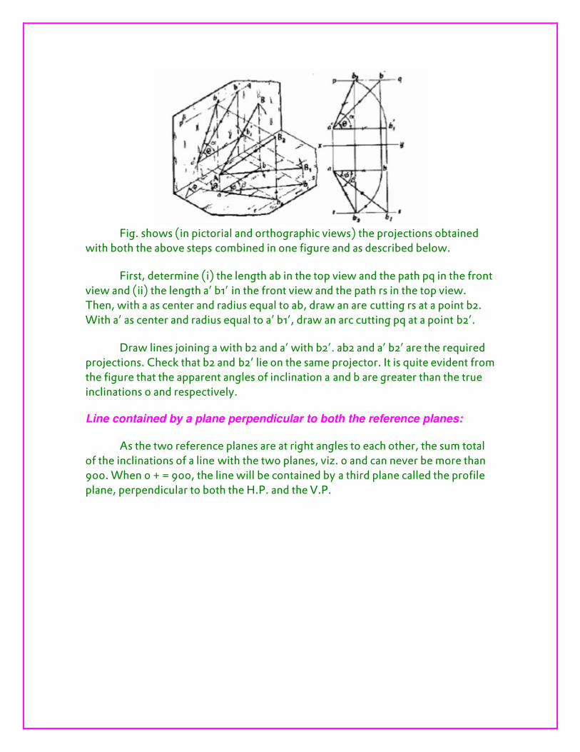
Fig. shows (in pictorial and orthographic views) the projections obtained
with both the above steps combined in one figure and as described below.
First, determine (i) the length ab in the top view and the path pq in the front view and (ii) the length a’ b1’ in the front view and the path rs in the top view. Then, with a as center and radius equal to ab, draw an are cutting rs at a point b2. With a’ as center and radius equal to a’ b1’, draw an arc cutting pq at a point b2’.
Draw lines joining a with b2 and a’ with b2’. ab2 and a’ b2’ are the required projections. Check that b2 and b2’ lie on the same projector. It is quite evident from the figure that the apparent angles of inclination a and b are greater than the true inclinations 0 and respectively. Line contained by a plane perpendicular to both the reference planes:
As the two reference planes are at right angles to each other, the sum total of the inclinations of a line with the two planes, viz. 0 and can never be more than 900. When 0 + = 900, the line will be contained by a third plane called the profile plane, perpendicular to both the H.P. and the V.P.

A line EF (fig) is inclined at 0 to the H.P. and at [equal to (900 – 0)] to the V.P. The line is thus contained by the profile plane marked P.P.
The front view e’ f’ and the top view ef are both perpendicular to xy and shorter than EF. Therefore, when a line is inclined o both the reference planes and contained by a plane perpendicular to them, i.e. when the sum of its inclinations with the H.P. and the V.P. is 900, its projections are perpendicular to xy and shorter than the true length.
True length of a straight line and its inclinations with the reference planes:
When projections of a line are given, its true length and inclinations with he planes are determined by the application of the following rule:
When a line is parallel to a plane, its projection on that plane will show its true length and the true inclination with the other plane.
The line may be made parallel to a plane, and its true length obtained by any one of the following three methods:
Method I
Making each view parallel to the reference line and projecting the other view from it.
Method II
Rotating the line about its projections till it lies in the H.P. or in the V.P.
Method III
Projecting the views on auxiliary planes parallel to each view.

The following problem shows the application of the first two methods.
Problem: The top view ab and the front view a’ b’ of a line AB are given. To determine its true length and the inclinations with the H.P. and the V.P.
Fig. (i) shows AB the line, a’ b’ its front view and ab its top view. If the trapezoid AB ba is tuned about Aa as axis, so that AB becomes parallel to the V.P., in the top view, b will move along an arc drawn with center a and radius equal to ab, to b1, so that ab1 is parallel to xy. In the front view, b’ will move along its locus pq, to a point b1’ on the projector through b1.
i. Therefore, with centre a and radius equal to ab [fig.(ii)], draw an arc to cut ef at b1. ii. Draw a projector through b1 to cut pq (the path of b1) at b1’.
iii. Draw the line a’ b1’ which is the true length of AB. The angle 0, which it makes with xy, is the inclination of AB with the H.P.
Again, in this fig. (i) AB is shown as a side of a trapezoid ABb’ a’. If the trapezoid is turned about Aa’ as axis so that AB is parallel to the H.P., the new top

view will show its true length and true inclination with the V.P.
i With a’ as centre and radius equal to a’ b’ fig.(ii), draw an arc to cut cd at b2’.
ii Draw a projector through b2’ to cut rs ( the path of b) at b2.
Iii.Draw the line ab2, which is the true length of AB. The angle which it makes with
xy is the inclination of AB with the V.P.
In the above figure, Fig. (i) shows the above two steps combined in one figure. The same results will be obtained by keeping the end B fixed and turning the end A in the previous
fig.(ii), as explained below.
i. With centre b and radius equal to ba, draw an arc cutting rs at a1 (thus making ba
parallel to xy).
ii. Project a1 to a‘1 on cd (the path of a’) a1’ b’ is the true length and 0 is the true
inclination of AB with the H.P.
iii. Similarly, with centre b’ and radius equal to b’ a’ draw an arc cutting pq at a2’.
iv. Project a2’ to a2 on ef (the path of a). a2b the true length and is the true
inclination of AB with the V.P.

Projections of Planes
Introduction
Plane figure
A plane figure or surface has only two dimension, viz., length and breadth. It has o thickness .a plane may be of any shape, such as triangular, square, pentagonal, hexagonal, circular etc.
Traces of Plane
A plane, extended if necessary, will meet the reference planes in lines unless it is parallel to one of them. These lines are called traces of the plane. Horizontal Trace (H.T.) of a plane is the line in which the plane meets the H.P.vertical trace (V.T.) of a plane is the line in which the plane meets the V.P.
Types of Planes
Planes may be divided into two types: a) perpendicular planes b) oblique planes
a. Perpendicular planes: the planes which are perpendicular to one or both the reference planes are called perpendicular planes. They can be sub-divided into the following three types:
i. Perpendicular to one plane and parallel to the other.
ii. Perpendicular to both the reference planes.
iii. Perpendicular to one plane and inclined to the other
b. Oblique planes: the planes which are inclined to both the reference planes are called oblique planes.
Problem1: Square laminas ABCD of side 25mm is perpendicular to H.P. and parallel to V.P. Draw its projections and obtain its traces.
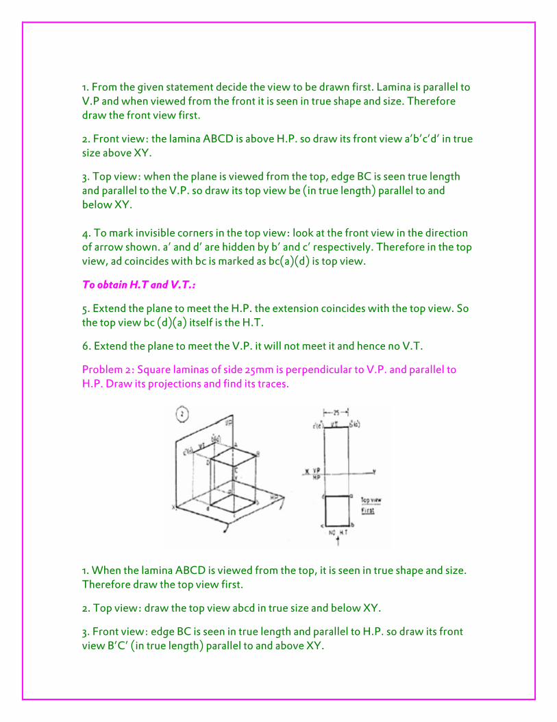
1. From the given statement decide the view to be drawn first. Lamina is parallel to V.P and when viewed from the front it is seen in true shape and size. Therefore draw the front view first.
2. Front view: the lamina ABCD is above H.P. so draw its front view a’b’c’d’ in true size above XY.
3. Top view: when the plane is viewed from the top, edge BC is seen true length and parallel to the V.P. so draw its top view be (in true length) parallel to and below XY. 4. To mark invisible corners in the top view: look at the front view in the direction of arrow shown. a’ and d’ are hidden by b’ and c’ respectively. Therefore in the top view, ad coincides with bc is marked as bc(a)(d) is top view.
To obtain H.T and V.T.:
5. Extend the plane to meet the H.P. the extension coincides with the top view. So the top view bc (d)(a) itself is the H.T.
6. Extend the plane to meet the V.P. it will not meet it and hence no V.T.
Problem 2: Square laminas of side 25mm is perpendicular to V.P. and parallel to H.P. Draw its projections and find its traces.
1. When the lamina ABCD is viewed from the top, it is seen in true shape and size. Therefore draw the top view first.
2. Top view: draw the top view abcd in true size and below XY.
3. Front view: edge BC is seen in true length and parallel to H.P. so draw its front view B’C’ (in true length) parallel to and above XY.
4. To mark the invisible corners in front view, look at the top view in the direction of arrow and a are hidden in the top view. So mark the invisible corners in the front view as (d’) and (a’).
5. Extend the lamina to meet the H.P. it will not meet H.P. and hence no H.T.
6. Extend the lamina to meet the V.P. hence front view b’c’ (d’) (a’) itself is the V.T.
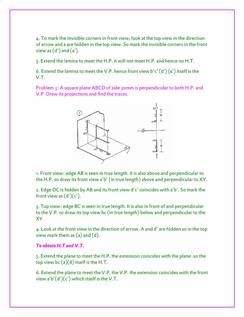
Problem 3: A square plane ABCD of side 30mm is perpendicular to both H.P. and V.P. Draw its projections and find the traces.
1. Front view: edge AB is seen in true length. It is also above and perpendicular to the H.P. so draw its front view a’b’ (in true length) above and perpendicular to XY.
2. Edge DC is hidden by AB and its front view d’c’ coincides with a’b’. So mark the front view as (d’)(c’).
3. Top view: edge BC is seen in true length. It is also in front of and perpendicular to the V.P. so draw its top view bc (in true length) below and perpendicular to the XY.
4. Look at the front view in the direction of arrow. A and d’ are hidden so in the top view mark them as (a) and (d).
To obtain H.T and V.T.
5. Extend the plane to meet the H.P. the extension coincides with the plane .so the top view bc (a)(d) itself is the H.T.
6. Extend the plane to meet the V.P. the V.P. the extension coincides with the front view a’b’(d’)(c’) which itself is the V.T.

Problem 4: Rectangular laminas ABCD is perpendicular to H.P. and inclined at to V.P. draw its projections and obtain the traces
1. When ABCD is viewed from the top, the edge BC is seen in true length. So draw the top view first.
2. Top view: the edge BC is in the front of and inclined at an angle of f to V.P. so draw its top view bc (in true length) below XY and inclined at f to XY.
3. Edge AD is hidden by BC and its top view (a)(d) coincides with bc. Now bc(a)(d) is the required top view.
4. Front view: when the lamina ABCD is viewed from front, front view a’b’c’d’ is seen in reduced size. The lamina is perpendicular to H.P. though the lamina is inclined to V.P. edges CD and AB are parallel to V.P. so draw the front view a’b’c’d’ such that a’b’=c’d’=AB.
To obtain H.T and V.T.
5. Extend the lamina to meet the H.P. the extension coincides with the top view. So the top view bc(a)(d) itself is the H.T.
6. Extend the lamina to meet the V.P. at which is the required V.T.

Related Documents


