316486 Automotive Chassis and Transmission A J Bhosale Government College of Engineering and Research, Avsari (Kd) Unit I- Vehicle Layouts, Front Axle and Steering Systems By, Mr. A J Bhosale Asst. Professor Dept. of Automobile Engineering Govt. College of Engineering and Research, Avsari (Kd)

Welcome message from author
This document is posted to help you gain knowledge. Please leave a comment to let me know what you think about it! Share it to your friends and learn new things together.
Transcript
316486 Automotive Chassis and Transmission A J Bhosale
Government College of Engineering and Research, Avsari (Kd)
Unit I-
Vehicle Layouts, Front Axle and
Steering Systems
By,
Mr. A J Bhosale
Asst. Professor
Dept. of Automobile Engineering
Govt. College of Engineering and Research, Avsari (Kd)
316486 Automotive Chassis and Transmission A J Bhosale
Government College of Engineering and Research, Avsari (Kd)
Contents:
1) Course Objectives and Outcomes
2) Syllabus
3) List of Experiments
4) Reference Books
5) Marking Scheme

316486 Automotive Chassis and Transmission A J Bhosale
Government College of Engineering and Research, Avsari (Kd)
COURSE OBJECTIVES
1.Understand types of vehicle layouts, front axle and
steering systems.
2. Gain knowledge of suspension systems.
3. Describe the types of wheels, tyres and braking systems.
4. Acquire the basic knowledge of Clutches and Gearbox.
5. Explain the effect of drive ratio and differential.
6. Memorize the basics of automatic transmission.
316486 Automotive Chassis and Transmission A J Bhosale
Government College of Engineering and Research, Avsari (Kd)
COURSE OUTCOMES
CO1. Classify vehicle layouts according to different enginelocations and ILLUSTRATE the working of front axle andsteering systems.
CO2. Define key elements of suspension system
CO3. Select wheels, tyres for particular application andRECITE basics of braking systems.
CO4. State the significance of clutch and gearbox inautomobile.
CO5. Summarize the working of final drive, differential anddrive line components
CO6. Evaluate performance characteristics of fluid flywheel,torque converter and epicyclic gearbox and AQUIRE basicknowledge of CVT and Automatic Transmission.

316486 Automotive Chassis and Transmission A J Bhosale
Government College of Engineering and Research, Avsari (Kd)
Syllabus
Unit – I Vehicle Layouts, Front Axle and Steering Systems
Introduction, Classification of automobile, Types of chassis
layout with reference to power plant locations and type of
drive, Types of chassis- fully forward, semi forward, Truck or
bus chassis, two & three wheeler chassis layout.
Functions of front axle, Types of front axle, Construction, Stub
axle and Wheel bearing, Front wheel steering Geometry –
castor, Camber, King pin inclination, toe-in, toe-out, Centre
point Steering, Self returning property, Adjusting and
checking of front wheel geometry, Ackerman and Davis
steering linkages, Steering system layout, Steering gear
boxes. (07 hrs.)

316486 Automotive Chassis and Transmission A J Bhosale
Government College of Engineering and Research, Avsari (Kd)
Unit – II Vehicle Suspension Systems
Road irregularities and need of suspension system, Types of
suspension system, Sprung and unsprung mass,
Suspension springs – requirements, types and
characteristics of leaf spring, coils spring, rubber spring,
air and torsion bar springs, Independent suspension for
front and rear, Types, Hydro-elastic suspension, Roll
centre, Use of anti-roll bar and stabilizer bar, Shock
absorbers – need, operating principles and types, Active
suspension. (07 hrs.)
316486 Automotive Chassis and Transmission A J Bhosale
Government College of Engineering and Research, Avsari (Kd)
Unit – III Wheels, Tyres and Braking Systems
Basic requirements of wheels and tyres, Types of road wheels,Construction of wheel assembly, wheel balancing, Tyreconstruction, material, types, tubeless, cross ply radial type, tyresizes and designation, Aspect ratio, tyre trade pattern, tyre valve,Tyre inflation pressure, safety precautions in tyres, Tyre rotationand matching, Types of Tyre wear and their causes, Selection oftyres under different applications, tyre retreading hot and cold,factors affecting tyre performance. Function and requirements ofbraking system, Types of brakes, Elementary theory of shoe brake,drum brake arrangement, disc brake arrangement, self-energizing,brake friction material. brake linkages, hydraulic brake system andcomponents, hydraulic brake fluids, air brakes, vacuum servoassisted brake, engine exhaust brake, parking brakes, dual powerbrake system, regenerative brake system, fail-safe brake, anti –lock brakes, anti-skid brakes, brake efficiency and testing, weighttransfer, braking ratio. (08 hrs.)

316486 Automotive Chassis and Transmission A J Bhosale
Government College of Engineering and Research, Avsari (Kd)
Unit – IV Clutches & Gear Box
Clutches: Principle, Functions, General requirements, Torquecapacity, Types of clutches, Cone clutch, Single-plate clutch,Diaphragm spring clutch, Multi-plate clutch, Centrifugalclutch, Electromagnetic clutch, Lining materials, Over-running clutch, Clutch control systems.
Gear Box: Necessity of gear box, Resistance to motion ofvehicle, Requirements of gear box, Functions of gear box,Types, Sliding mesh, Constant mesh, Synchromesh.Principle, construction and working of synchronizing unit,Requirements & applications of helical gears, Gear selectormechanism, Two wheeler gear box, Lubrication of gear box,Overdrive gears, Performance characteristics.
(08 hrs.)
316486 Automotive Chassis and Transmission A J Bhosale
Government College of Engineering and Research, Avsari (Kd)
Unit – V Drive Lines, Final Drive & Rear Axle
Effect of driving thrust and torque reaction, propeller shaft-
universal joints, hooks and constant velocity U.J., Drive
line arrangements – Hotchkiss drive & torque tube drive,
Rear wheel drive & front wheel drive layouts .
Purpose of final drive & drive ratio, Different types of final
drives, need of differential, Constructional details of
differential unit, Non-slip differential, Differential lock,
Differential housing, Function of rear axle, Construction,
Types of loads acting on rear axle, Axle types - semi-
floating, full floating, three quarter floating, Axle shafts,
Final drive lubrication. (07 hrs.)

316486 Automotive Chassis and Transmission A J Bhosale
Government College of Engineering and Research, Avsari (Kd)
Unit – V Automatic Transmission
Fluid Flywheel, Torque convertor: Operating principle, Constructionand working of fluid flywheel, Characteristics, Advantages &limitations of fluid coupling, Torque convertor, and constructionand working of torque converter, Performance characteristics,Comparison with conventional gear box.
Epicyclic Gear Boxes: Simple epicyclic gear train, Gear ratios,Simple & compound planet epicyclic gearing, Epicyclicgearboxes, Wilson epicyclic gear train - Construction andoperation, Advantages, Clutches and brakes in epicyclic gear train,compensation for wear, performance characteristics.
Principle of semi automatic & automatic transmission, Hydramatictransmission, Fully automatic transmission, Semi automatictransmission, Hydraulic control system, Continuous variabletransmission (CVT) – operating principle, basic layout andoperation, Advantages and disadvantages. (08 hrs.)
316486 Automotive Chassis and Transmission A J Bhosale
Government College of Engineering and Research, Avsari (Kd)
List of Experiments: (Any 8 Experiments from Experiments No. 1 to 10.Experiment No.11 is Compulsory)
1. To Study different vehicle layouts.
2. Demonstration of steering, suspension & braking system used in automobiles.
3. Adjustments, overhauling, and repair of Two Wheeler Clutch
4. Adjustments, overhauling, and repair of Four Wheeler Clutch (Light / HeavyDuty Vehicle).
5. Adjustments, overhauling, and repair Constant Mesh Gearbox and SynchromeshGearbox.
6. Adjustments, overhauling, and repair of Drive Line (Universal Joint, PropellerShaft, Slip Joint).
7. Adjustments, overhauling, and repair of Final Drive & Differential.
8. Demonstration and study different types of Front and Rear Axles.
9. To study Fluid Flywheel and Torque Converter.
10. To study Continuous Variable Transmission (CVT).
11. Any One Visit from Below
a) Visit to Vehicle Service Station to Study Power Transmission of Vehicle
b) Visit to any Automotive Industry for Vehicle Transmission / Assembly Line.
316486 Automotive Chassis and Transmission A J Bhosale
Government College of Engineering and Research, Avsari (Kd)
Text Books:
1. Dr. Kripal Singh, “Automobile Engineering-Vol. 1”, 13th Edition, Standard PublishersDistributors.
2. N. K. Giri, “Automotive Mechanics”, Khanna Publishers, Delhi, Eighth Edition
3. C. P. Nakra ,“Basic Automobile Engineering”, Dhanpat Rai Publishing Company (Pvt)Ltd.
Reference Books:
1. Bosch “Automotive Handbook”, Robert Bosch GmbH, Germany.
2. W. H. Crouse and D. L. Anglin ,“Motor Vehicle Inspection”,
3. Ramlingam , “Automobile Engineering” (Anna University )
4. Josepf Heitner , “Automotive Mechanics”.
5. J.G .Giles “Vehicle Operation and Performance”.
6. George Pieters, Barbara Pieters, “Automotive Vehicle Safety”.
7. Jousha H. M, “Engine performance Diagnosis and Tune up Shop Manual”.
8. Newton, Steed & Garrot, “Motor Vehicles”, 13th Edition, Butterworth London
9. W. Judge, “Modern Transmission”, Chapman & Hall Std., 1989,
10. Chek Chart, “Automatic Transmission”,A Harper & Raw Publications,
11. Heisler, “Vehicle and Engine Technology”, Second Edition, SAE InternationalPublication.

316486 Automotive Chassis and Transmission A J Bhosale
Government College of Engineering and Research, Avsari (Kd)
Marking Scheme
316486 Automotive Chassis and Transmission A J Bhosale
Government College of Engineering and Research, Avsari (Kd)
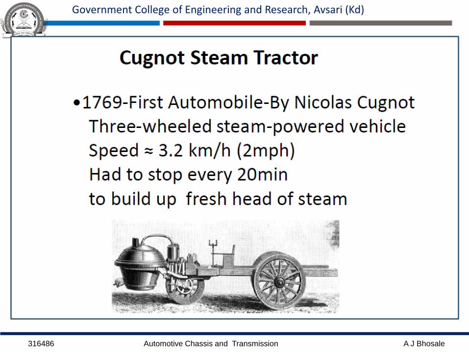
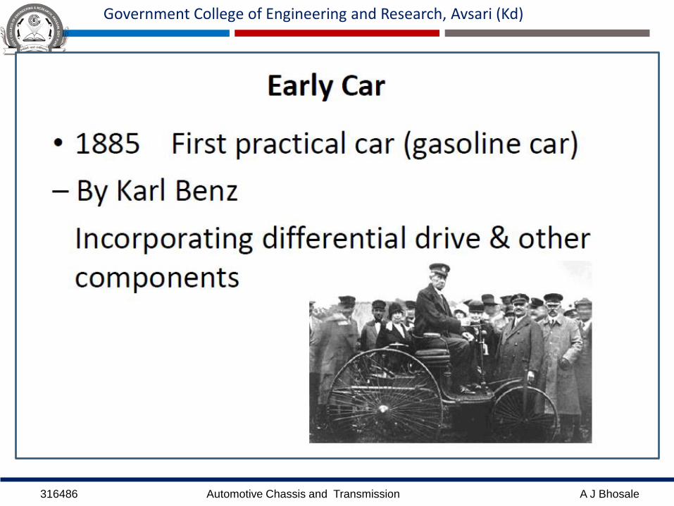
Introduction:
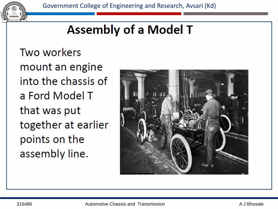
The automobile as we know, it was not invented in a
single day by a single inventor. The history of the
automobile reflects an evolution that took place
worldwide.
It is estimated that over 100,000 patents created the
modern automobile.

316486 Automotive Chassis and Transmission A J Bhosale
Government College of Engineering and Research, Avsari (Kd)

316486 Automotive Chassis and Transmission A J Bhosale
Government College of Engineering and Research, Avsari (Kd)

316486 Automotive Chassis and Transmission A J Bhosale
Government College of Engineering and Research, Avsari (Kd)

316486 Automotive Chassis and Transmission A J Bhosale
Government College of Engineering and Research, Avsari (Kd)
316486 Automotive Chassis and Transmission A J Bhosale
Government College of Engineering and Research, Avsari (Kd)

316486 Automotive Chassis and Transmission A J Bhosale
Government College of Engineering and Research, Avsari (Kd)

316486 Automotive Chassis and Transmission A J Bhosale
Government College of Engineering and Research, Avsari (Kd)

316486 Automotive Chassis and Transmission A J Bhosale
Government College of Engineering and Research, Avsari (Kd)
316486 Automotive Chassis and Transmission A J Bhosale
Government College of Engineering and Research, Avsari (Kd)

316486 Automotive Chassis and Transmission A J Bhosale
Government College of Engineering and Research, Avsari (Kd)

316486 Automotive Chassis and Transmission A J Bhosale
Government College of Engineering and Research, Avsari (Kd)
316486 Automotive Chassis and Transmission A J Bhosale
Government College of Engineering and Research, Avsari (Kd)
316486 Automotive Chassis and Transmission A J Bhosale
Government College of Engineering and Research, Avsari (Kd)

316486 Automotive Chassis and Transmission A J Bhosale
Government College of Engineering and Research, Avsari (Kd)

316486 Automotive Chassis and Transmission A J Bhosale
Government College of Engineering and Research, Avsari (Kd)
316486 Automotive Chassis and Transmission A J Bhosale
Government College of Engineering and Research, Avsari (Kd)
316486 Automotive Chassis and Transmission A J Bhosale
Government College of Engineering and Research, Avsari (Kd)
316486 Automotive Chassis and Transmission A J Bhosale
Government College of Engineering and Research, Avsari (Kd)

316486 Automotive Chassis and Transmission A J Bhosale
Government College of Engineering and Research, Avsari (Kd)
316486 Automotive Chassis and Transmission A J Bhosale
Government College of Engineering and Research, Avsari (Kd)

316486 Automotive Chassis and Transmission A J Bhosale
Government College of Engineering and Research, Avsari (Kd)

316486 Automotive Chassis and Transmission A J Bhosale
Government College of Engineering and Research, Avsari (Kd)

316486 Automotive Chassis and Transmission A J Bhosale
Government College of Engineering and Research, Avsari (Kd)
316486 Automotive Chassis and Transmission A J Bhosale
Government College of Engineering and Research, Avsari (Kd)

316486 Automotive Chassis and Transmission A J Bhosale
Government College of Engineering and Research, Avsari (Kd)
Classification of Automobiles
1. Capacity (HMV ,LMV)
2. Power ( Petrol, Diesel, Gas, Electric)
3. Use (Cars ,Buses ,Trucks ,Motor Cycles )
4. Wheels (2.3.4.6 ….)
5. Make ( Bajaj, Vespa, Hero, Honda, Maruti)
6. Drive (LHD, RHD)
7. Transmission ( Conventional, Automatic)
8. Purpose (Passenger,Goods)
316486 Automotive Chassis and Transmission A J Bhosale
Government College of Engineering and Research, Avsari (Kd)
Chassis:
Chassis is a French term which denotes the whole
vehicle except body in case of heavy vehicles.
In case of light vehicles of mono construction it denotes
the whole body except additional fitting in the body.
Chassis consists of engine, brakes, steering system &
wheel mounted on the frame, differential, suspension.
Propel and control a automobile.

316486 Automotive Chassis and Transmission A J Bhosale
Government College of Engineering and Research, Avsari (Kd)
ITS PRINCIPAL FUNCTION:
To safely carry the maximum load.
Holding all components together while driving.
Accommodate twisting on even road surface.
Endure shock loading.
It must absorb engine & driveline torque.

316486 Automotive Chassis and Transmission A J Bhosale
Government College of Engineering and Research, Avsari (Kd)
CLASSIFICATION OF CHASSIS
According to control:
Conventional-forward chassis
Semi-forward chassis
Full-forward chassis

316486 Automotive Chassis and Transmission A J Bhosale
Government College of Engineering and Research, Avsari (Kd)
Conventional chassis:
Engine is fitted in front of the driver cabin or driver seat
such as in cars.
Chassi portion can not be utilized for carrying passengers
and goods

316486 Automotive Chassis and Transmission A J Bhosale
Government College of Engineering and Research, Avsari (Kd)

316486 Automotive Chassis and Transmission A J Bhosale
Government College of Engineering and Research, Avsari (Kd)
Semi-forward chassis
• Half portion of the engine is in the driver cabin and
remaining half is outside the cabin such as in Tata trucks
• In this arrangement a part of the chassis is utilized for
carrying extra passengers

316486 Automotive Chassis and Transmission A J Bhosale
Government College of Engineering and Research, Avsari (Kd)
316486 Automotive Chassis and Transmission A J Bhosale
Government College of Engineering and Research, Avsari (Kd)
Full-forward chassis
Complete engine is mounted inside the driver cabin
Driver seat is just above the front wheel

316486 Automotive Chassis and Transmission A J Bhosale
Government College of Engineering and Research, Avsari (Kd)

316486 Automotive Chassis and Transmission A J Bhosale
Government College of Engineering and Research, Avsari (Kd)
Chassis Layouts

316486 Automotive Chassis and Transmission A J Bhosale
Government College of Engineering and Research, Avsari (Kd)
Bus Chassis

316486 Automotive Chassis and Transmission A J Bhosale
Government College of Engineering and Research, Avsari (Kd)
Car
Bodies

316486 Automotive Chassis and Transmission A J Bhosale
Government College of Engineering and Research, Avsari (Kd)
Chassis Classification Based on engine location
Engine fitted at front
Engine fitted at Back
Engine fitted at centre

316486 Automotive Chassis and Transmission A J Bhosale
Government College of Engineering and Research, Avsari (Kd)
Engine fitted at front:
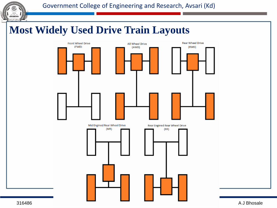
1. Power is given to Rear Wheels (Rear Wheel Drive)
Advantages:
1. Enough space is available for luggage behind the rear seat
2. The weight of vehicles is well balance
3. Increased efficiency of cooling system
4. Steering mechanism is simple in design
5. The weight of vehicle is shifted to rear driving wheels during
acceleration and on steeps resulting in better road grip,
hence, there are less chances of wheel slipping .
6. Accessibility to various components like engine , gear box
and rear axle is better in comparison to other layout

316486 Automotive Chassis and Transmission A J Bhosale
Government College of Engineering and Research, Avsari (Kd)
Disadvantages:
1. During the braking, weight of vehicle is shifted to front
wheels and weight on rear wheels decreased, results in
decreased braking effort developed
2. It requires long propeller shaft and differential at rear,
therefore height of floor area is increased. Also, due to
long propeller shaft transmission problems and weight is
increased.
3. Due to less weight on driving rear wheels, there is less
adhesion on road and result in less holding capacity.
Therefore there is chance of slipping on slippery surface.

316486 Automotive Chassis and Transmission A J Bhosale
Government College of Engineering and Research, Avsari (Kd)

316486 Automotive Chassis and Transmission A J Bhosale
Government College of Engineering and Research, Avsari (Kd)

316486 Automotive Chassis and Transmission A J Bhosale
Government College of Engineering and Research, Avsari (Kd)
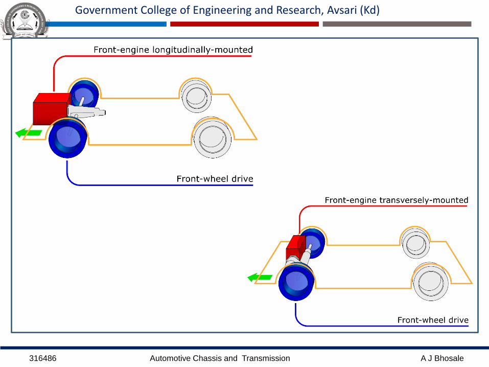
Engine fitted at front:
2. Power is given to Front Wheels (Front Wheel Drive)
1. Longitudinally fitted engine
2. Transversely fitted engine
Advantages:
1. Low floor is available.
2. clutch, gear box & differential are usually made as one
unit, thereby cost is reduced.
3. Due to more weight placed on driving front wheel, the
vehicle has more adhesion on road. Hence good road
holding capacity even on the curves and slippery roads .
316486 Automotive Chassis and Transmission A J Bhosale
Government College of Engineering and Research, Avsari (Kd)
Disadvantages:
1. The weight on the driving front wheels is reduced during
acceleration and climbing of steep gradient due to weight of the
vehicle shifting to the rear wheels. Hence, result in decreased
tractive effort.
2. This disadvantage become more serious on slippery gradient.
3. The steering mechanism become more complicated due to
accommodation of engine, clutch, gearbox & final drive all at
front of vehicle.
316486 Automotive Chassis and Transmission A J Bhosale
Government College of Engineering and Research, Avsari (Kd)

316486 Automotive Chassis and Transmission A J Bhosale
Government College of Engineering and Research, Avsari (Kd)
316486 Automotive Chassis and Transmission A J Bhosale
Government College of Engineering and Research, Avsari (Kd)
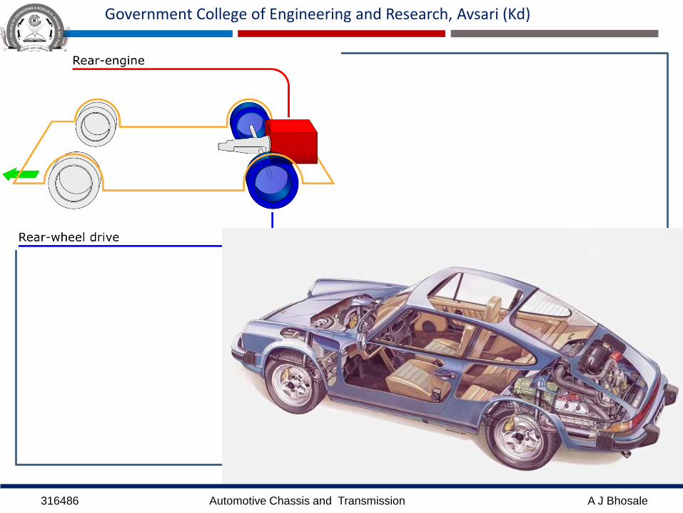
Engine fitted at Back:
1. Flat floor is available since long propeller shafts are eliminated
2. With elimination of propeller shaft the centre of gravity loweredgiving stable driving
3. Better adhesion on road specially when climbing hill.
4. While Climbing hills proper adhesion may be affected since theweight of vehicles moves to the rear, thereby reducing the weighton the front wheel.
5. As a result of grouping of the engine with clutch, gear box anddifferential, the repair and adjustment become difficult due tocongestion at the rear.
6. Long linkages are required to connect the control panel andengine, gear box, accelerator and clutch.
7. Efficient cooling becomes very difficult to obtain due to airpasses through side part of the body
316486 Automotive Chassis and Transmission A J Bhosale
Government College of Engineering and Research, Avsari (Kd)

316486 Automotive Chassis and Transmission A J Bhosale
Government College of Engineering and Research, Avsari (Kd)
Engine fitted at centre
Drive is given to the rear
As in royal tiger world master buses
This arrangement provide full space of floor for use
316486 Automotive Chassis and Transmission A J Bhosale
Government College of Engineering and Research, Avsari (Kd)

316486 Automotive Chassis and Transmission A J Bhosale
Government College of Engineering and Research, Avsari (Kd)
AWD or 4WD• All wheel drive (AWD) is a drivetrain configuration engineered to direct
power to all four wheels of a car simultaneously.
• All wheel drive (AWD) train system includes a differential between the
front and rear drive shafts.

316486 Automotive Chassis and Transmission A J Bhosale
Government College of Engineering and Research, Avsari (Kd)

316486 Automotive Chassis and Transmission A J Bhosale
Government College of Engineering and Research, Avsari (Kd)
WHY 4WD ARE USED?
• To get enough “TRACTION” between wheels and road
surfaces.
• To move vehicle on slick surfaces, dirt, slippery roads,
sand roads and snowy, muddy roads etc.

316486 Automotive Chassis and Transmission A J Bhosale
Government College of Engineering and Research, Avsari (Kd)
ADVANTAGES
• Increased Traction is obtained in slippery surfaces.
• More balanced axle load distribution.
• Even tire wear.
DISADVANTAGES
• Weight of vehicle is increased.
• Cost vehicle is increased.
• Maximum speed of vehicle is reduced.
• Less fuel economy than 2WD.
316486 Automotive Chassis and Transmission A J Bhosale
Government College of Engineering and Research, Avsari (Kd)
Most Widely Used Drive Train Layouts

316486 Automotive Chassis and Transmission A J Bhosale
Government College of Engineering and Research, Avsari (Kd)
316486 Automotive Chassis and Transmission A J Bhosale
Government College of Engineering and Research, Avsari (Kd)
Motor-cycle Frames
• The purpose of a motorcycles frame is to act as a baseonto which all the various components can be bolted to.
• The engine generally sits inside the frame, the rearswing arm is attached by a pivot bolt (allowing thesuspension to move) and the front forks are attached tothe front of the frame.
• The frame can also help to protect the more sensitiveparts of a motorcycle in a crash.
• Motorcycle frames are usually made from weldedaluminum, steel, magnesium or metal alloy. Carbon-fibre is sometimes used in expensive or custom frames.

316486 Automotive Chassis and Transmission A J Bhosale
Government College of Engineering and Research, Avsari (Kd)
A motorcycle frame is the backbone of the design and
overall aesthetics of the motorcycle. The frame can
either make or break a motorcycle’s form and function.
TYPES OF FRAME
Single Cradle frame
Double cradle frame
Backbone frame
Perimeter frame
Monocoque frame
Trellis frame

316486 Automotive Chassis and Transmission A J Bhosale
Government College of Engineering and Research, Avsari (Kd)
1.Single cradle frame

316486 Automotive Chassis and Transmission A J Bhosale
Government College of Engineering and Research, Avsari (Kd)
• The single cradle is the simplest type of
motorcycle frame, and looks similar to
the first ever motorcycle frames.
• It is made from steel tubes that surround
the engine with a main tube above and
other, smaller diameter tubes beneath.
• If a single cradle becomes double at the
exhaust, as frequently occurs, it is
referred to as a split single cradle frame.
• Single cradle frames are usually found
in off-road motorcycles.
Yamaha SR500E

316486 Automotive Chassis and Transmission A J Bhosale
Government College of Engineering and Research, Avsari (Kd)
2. Double cradle frame

316486 Automotive Chassis and Transmission A J Bhosale
Government College of Engineering and Research, Avsari (Kd)

316486 Automotive Chassis and Transmission A J Bhosale
Government College of Engineering and Research, Avsari (Kd)
• Double cradle frames are descended fromsingle cradle frames.
• They consist of two cradles that support theengine one either side.
• Double cradle frames are commonly used incustom motorcycles and simpler road bikes.
• They offer a good compromise betweenrigidity, strength and lightness, though theyhave now been technically surpassed byperimeter frames.
• Bajaj: Platina 100, Discover 100/125/150,Pulsar 150/180/220, Avenger 220
• Hero: CD Dawn/Deluxe, Splendor, SplendorNXG, Passion, Super Splendor, Glamour
Suzuki GSX600R
316486 Automotive Chassis and Transmission A J Bhosale
Government College of Engineering and Research, Avsari (Kd)
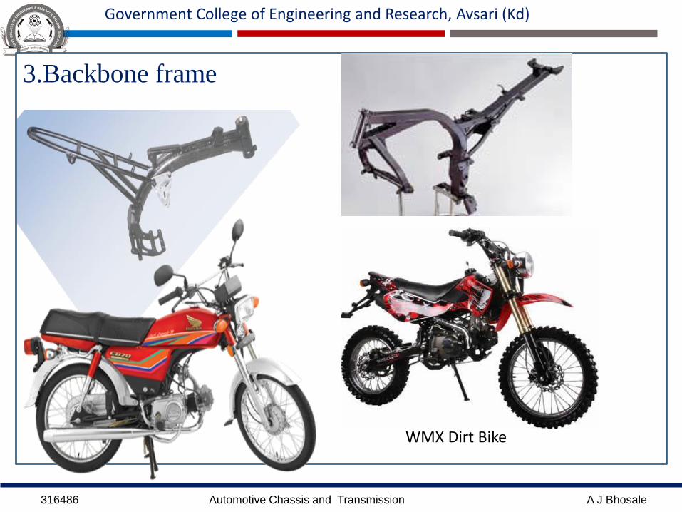
3.Backbone frame
WMX Dirt Bike

316486 Automotive Chassis and Transmission A J Bhosale
Government College of Engineering and Research, Avsari (Kd)
• The most desirable frame around.
• Comprises a single, wide main beam from which the
engine is suspended.
• Allows for great flexibility in design, since it is
concealed inside the finished motorcycle.
• The engine just seems to hang in mid air.
• It is simple and cheap to make.
• Used mainly on naked and off‐road motorcycles.
• Hero Honda CD100

316486 Automotive Chassis and Transmission A J Bhosale
Government College of Engineering and Research, Avsari (Kd)
4.Perimeter frame
BBR Perimeter CRF

316486 Automotive Chassis and Transmission A J Bhosale
Government College of Engineering and Research, Avsari (Kd)
• Research has shown that major advantages are to be gainedin terms of rigidity by joining the steering head to the swingarm in as short a distance as possible.
• Flexure and torsion are dramatically reduced.
• This is the concept behind the perimeter frame.
• Two robust beams descend in the most direct way possiblefrom the steering head to the swing arm, passing around theengine
• These frames originated on racing motorcycles.
• They were originally made from steel but most are madefrom aluminum nowadays to save weight.
• Once the advantages of this frame were seen, they wereadopted by most motorcycle manufacturers.
• Bajaj Pulsar 200NS, Yamaha R15

316486 Automotive Chassis and Transmission A J Bhosale
Government College of Engineering and Research, Avsari (Kd)
5. Monocoque frame

316486 Automotive Chassis and Transmission A J Bhosale
Government College of Engineering and Research, Avsari (Kd)
• Used nearly exclusively on competition bikes and is
very rarely found on road‐going bikes.
• Act as a single piece unit that functions as seat
mounting, tank and tail section.
• Though they offer certain advantages in terms of
rigidity, monocoque frames are heavy and generally not
worth the effort.
• They are used almost exclusively on specialized
competition bikes and are not a good choice for street
bikes.
• Ducati Panigale 1199.
316486 Automotive Chassis and Transmission A J Bhosale
Government College of Engineering and Research, Avsari (Kd)
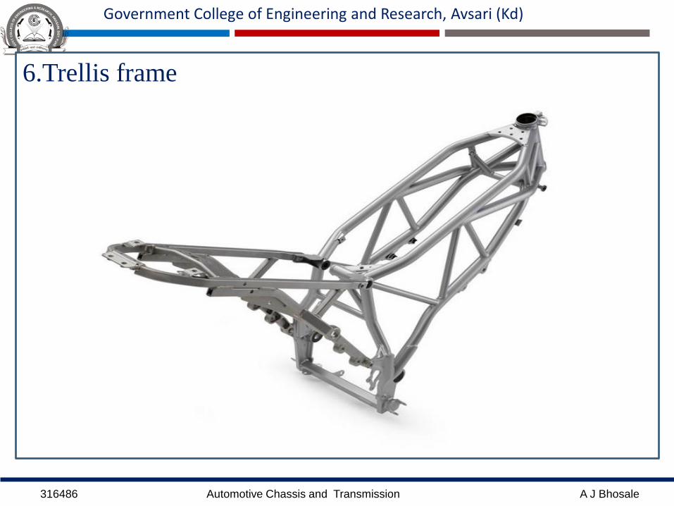
6.Trellis frame

316486 Automotive Chassis and Transmission A J Bhosale
Government College of Engineering and Research, Avsari (Kd)
• The trellis frame rivals the aluminum perimeter framefor rigidity and weight.
• A favorite of Italian and European manufacturers it hasproved a great success in racing and competition.
• The Trellis frame uses the same principles as theperimeter frame, and connects the steering head andswing arm as directly as possible.
• The frame is made up of a large number of short steel(or aluminum) tubes welded together to form a trellis.
• The trellis frame is not only easy to manufacture butextremely strong as well. The frame pictures is fromthe Suzuki SV650S.

316486 Automotive Chassis and Transmission A J Bhosale
Government College of Engineering and Research, Avsari (Kd)
Custom Built Frames

316486 Automotive Chassis and Transmission A J Bhosale
Government College of Engineering and Research, Avsari (Kd)
Three Wheeler Frames
316486 Automotive Chassis and Transmission A J Bhosale
Government College of Engineering and Research, Avsari (Kd)
Axle:
An axle is a central shaft for a rotating wheel or gear.
On wheeled vehicles, the axle may be fixed to the wheels, rotating with
them, or fixed to the vehicle, with the wheels rotating around the axle.
Bearings or bushings are provided at the mounting points where the axle is
supported.

316486 Automotive Chassis and Transmission A J Bhosale
Government College of Engineering and Research, Avsari (Kd)
Types of Axles
REAR AXLE
• Full Floating
• Semi Floating
• Three Quarter Floating
FRONT AXLE
• Dead Front Axle
• Live Front Axle
STUB AXLE
• Elliot
• Reversed Elliot
• Lamoine
• Reversed Lamoine

316486 Automotive Chassis and Transmission A J Bhosale
Government College of Engineering and Research, Avsari (Kd)
Front Axle:- Functions
It supports the weight of front part of the vehicle.
It facilitates steering knuckles and suspension springs.
It transmits weight of vehicle through springs to the front wheels.
It absorbs torque applied on it due to braking of vehicle.

316486 Automotive Chassis and Transmission A J Bhosale
Government College of Engineering and Research, Avsari (Kd)
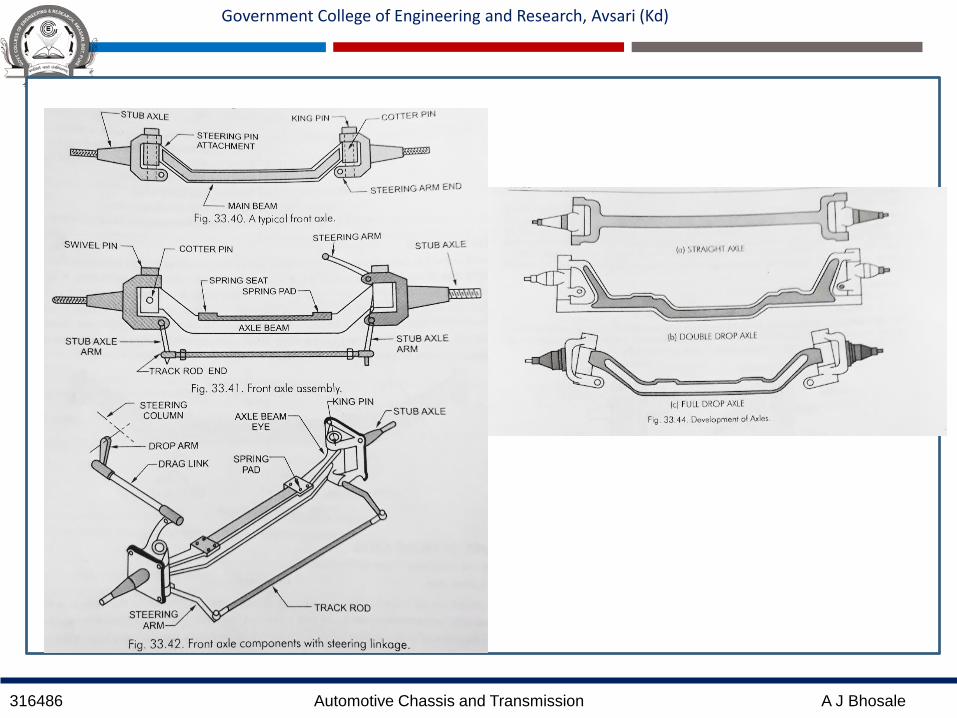
Front Axle
• The front axle is designed to transmit the weight of the automobile from the springs to
the front wheels, turning right or left as required.
• To prevent interference due to front engine location, and for providing greater stability
and safety at high speeds by lowering the centre of gravity of the road vehicles, the entire
centre portion of the axle is dropped.
• As shown in Fig. front axle includes the axle-beam, stub-axles, ack-rod and stub-axle
arm.

316486 Automotive Chassis and Transmission A J Bhosale
Government College of Engineering and Research, Avsari (Kd)
Front axles can be live axles and dead axles.
A live front axle contains the differential mechanism through which theengine power flows towards the front wheels.
For steering the front wheels, constant velocity joints are contained inthe axle half shafts.
Without affecting the power flow through the half shafts, these jointshelp in turning the stub axles around the king-pin.
The front axles are generally dead axles, which does not transmit power.
The front wheel hubs rotate on anti-friction bearings of tapered-rollertype on the steering spindles, which are an integral part of steeringknuckles.
To permit the wheels to be turned by the steering gear, the steeringspindle and steering knuckle assemblies are hinged on the end of axle.
The pin that forms the pivot of this hinge is known as king pin orsteering knuckle pin.
316486 Automotive Chassis and Transmission A J Bhosale
Government College of Engineering and Research, Avsari (Kd)
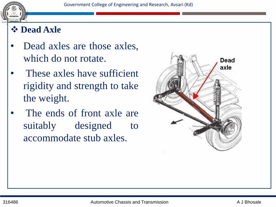
Dead Axle
• Dead axles are those axles,
which do not rotate.
• These axles have sufficient
rigidity and strength to take
the weight.
• The ends of front axle are
suitably designed to
accommodate stub axles.

316486 Automotive Chassis and Transmission A J Bhosale
Government College of Engineering and Research, Avsari (Kd)

316486 Automotive Chassis and Transmission A J Bhosale
Government College of Engineering and Research, Avsari (Kd)
Live Axle
• Live axles are used to transmit power from gear
box to front wheels.
• Live front axles although, resemble rear axles
but they are different at the ends where wheels
are mounted. Maruti-800 has line front axle.

316486 Automotive Chassis and Transmission A J Bhosale
Government College of Engineering and Research, Avsari (Kd)
316486 Automotive Chassis and Transmission A J Bhosale
Government College of Engineering and Research, Avsari (Kd)
316486 Automotive Chassis and Transmission A J Bhosale
Government College of Engineering and Research, Avsari (Kd)
Stub Axle:
• Stub axles are connected to the front axle by king pins. Front wheels are
mounted on stub axles arrangement for steering. Stub axle turns on king
pins. King pins is fitted in the front axle beam eye and is located and locked
there by a taper cotter pin. Stub axles are of four types:
Elliot
Reversed Elliot
Lamoine
Reversed Lamoine
• Material- 3% Nickel steel and alloy steel containing chromium and
molybdenum, made by forging.

316486 Automotive Chassis and Transmission A J Bhosale
Government College of Engineering and Research, Avsari (Kd)

316486 Automotive Chassis and Transmission A J Bhosale
Government College of Engineering and Research, Avsari (Kd)
316486 Automotive Chassis and Transmission A J Bhosale
Government College of Engineering and Research, Avsari (Kd)
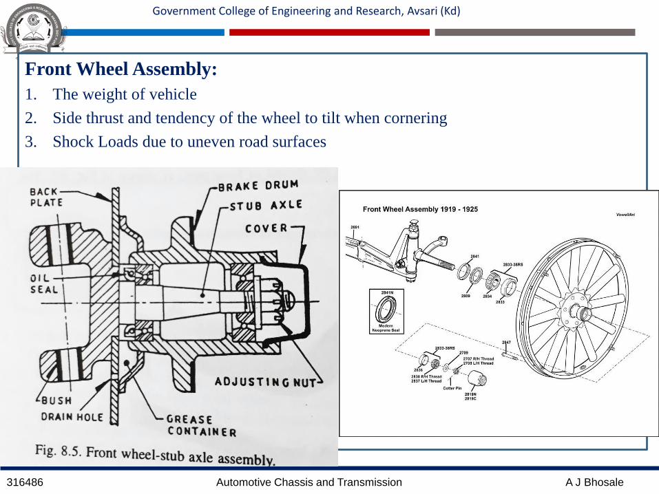
Front Wheel Assembly:
1. The weight of vehicle
2. Side thrust and tendency of the wheel to tilt when cornering
3. Shock Loads due to uneven road surfaces

316486 Automotive Chassis and Transmission A J Bhosale
Government College of Engineering and Research, Avsari (Kd)
Steering System:
• Steering is the term applied to the collection of components, linkages, etc.
which will allow a vehicle to follow the desired course.
• The front wheels are supported on front axle so that they can swing to left or
right for steering. This movement is produced by gearing and linkage
between the steering wheel in front of the driver and the steering knuckle or
wheel.
• The complete arrangement is called “Steering System”.
• The function of steering system is to convert the rotary movement of the
steering wheel into angular turn of the front wheels.
• The steering system also absorb a large part of the road shocks, thus
preventing them from being transmitted to the driver.

316486 Automotive Chassis and Transmission A J Bhosale
Government College of Engineering and Research, Avsari (Kd)

316486 Automotive Chassis and Transmission A J Bhosale
Government College of Engineering and Research, Avsari (Kd)
Requirements:
• It should multiply the turning effort applied on the steering wheel by the
driver.
• It should not transmit the shocks of the road surface encountered by wheels
to the driver hands.
• The mechanism should have self-returning property so that when the driver
releases the steering wheel after negotiating the turn, the wheel should try to
achieve straight ahead position.
• It should be very accurate and easy to handle.
316486 Automotive Chassis and Transmission A J Bhosale
Government College of Engineering and Research, Avsari (Kd)
Functions:
It helps in swinging or turning the wheels to the left or right (at the will of
driver).
It converts the rotary movement of the steering wheel into an angular turn of
the front wheels.
It multiplies the effort of the driver by leverage in order to make it fairly
easy to turn the wheels.
It absorbs a major part of the road shocks thereby preventing them to get
transmitted to the hands of the driver
It provides directional stability.
It helps in achieving the self-returning effect.
Perfect Steering condition.
Minimize tyre wear.

316486 Automotive Chassis and Transmission A J Bhosale
Government College of Engineering and Research, Avsari (Kd)
Front wheel steering Geometry:
The term "steering geometry" (also known as "front-end geometry") refers to
the angular Relationship between suspension and steering parts, front wheels,
and the road surface. Because alignment deals with angles and affects steering,
the method of describing alignment measurements is called steering geometry.
1. Castor
2. Camber
3. King Pin Inclination (Steering axis Inclination)
4. Scrub Radius
5. Toe-in or Toe- Out
316486 Automotive Chassis and Transmission A J Bhosale
Government College of Engineering and Research, Avsari (Kd)
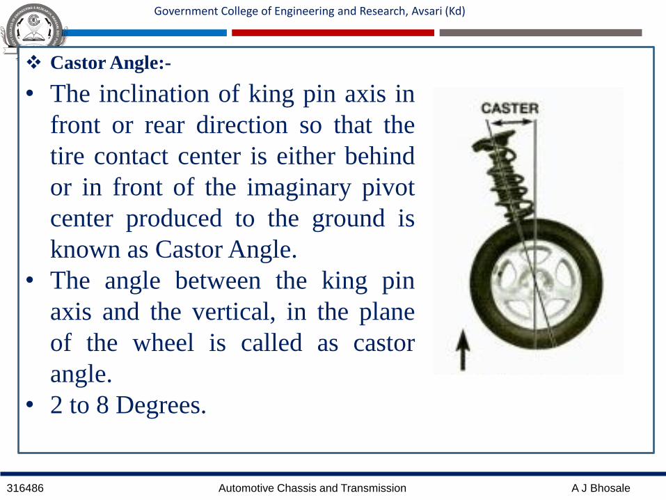
Castor Angle:-
• The inclination of king pin axis in
front or rear direction so that the
tire contact center is either behind
or in front of the imaginary pivot
center produced to the ground is
known as Castor Angle.
• The angle between the king pin
axis and the vertical, in the plane
of the wheel is called as castor
angle.
• 2 to 8 Degrees.

316486 Automotive Chassis and Transmission A J Bhosale
Government College of Engineering and Research, Avsari (Kd)

316486 Automotive Chassis and Transmission A J Bhosale
Government College of Engineering and Research, Avsari (Kd)
Effect of Castor Angle:
316486 Automotive Chassis and Transmission A J Bhosale
Government College of Engineering and Research, Avsari (Kd)
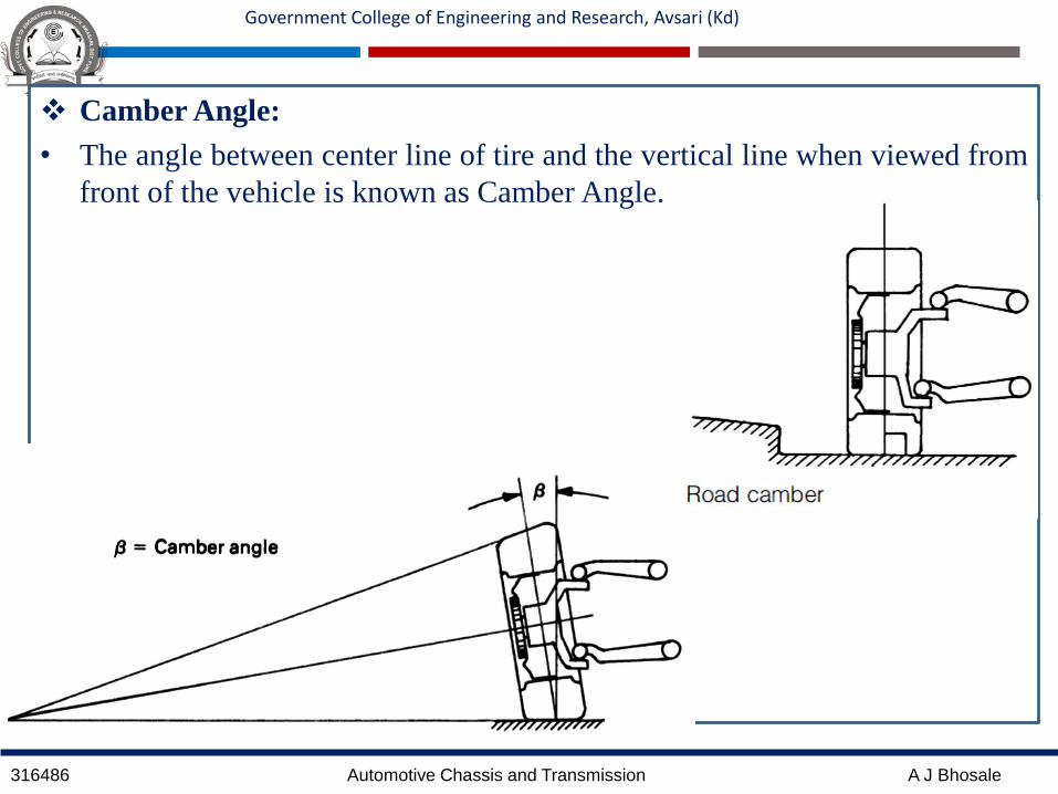
Camber Angle:
• The angle between center line of tire and the vertical line when viewed from
front of the vehicle is known as Camber Angle.

316486 Automotive Chassis and Transmission A J Bhosale
Government College of Engineering and Research, Avsari (Kd)
• If the top of the wheel (when viewed from front) leans
outward than bottom it is positive camber conversely if
bottom of the wheel is outward than the top it is negative
camber.
• Generally, it should not exceed 2 Degrees.
• Positive camber is used on most of vehicles.
• Positive camber increases steering effort.
• Negative camber is used on racing cars to provide
directional stability and reduce steering effort.

316486 Automotive Chassis and Transmission A J Bhosale
Government College of Engineering and Research, Avsari (Kd)
King Pin Inclination or Steering Axis Inclination:
• The angle between the vertical line and the center of the
king pin or steering axis when viewed from front off the
vehicle is known as KPI or SAI.
• The KPI in combination with Castor angle is used to
provide the directional stability in modern cars by tending
to return the wheels to straight ahead position after any
turn.
• This inclination varies from
4 to 8 degree in modern cars.

316486 Automotive Chassis and Transmission A J Bhosale
Government College of Engineering and Research, Avsari (Kd)
This inclination,
Helps in a straight ahead recovery and
provides directional stability
Reduces the wear and tear of the tyres
Tends to reduce the effect of road shock
on the steering system
Incorrect steering inclination leads to,
Hard steering
Pulling of vehicle to a side
Wheel doesn’t return to straight ahead
position

316486 Automotive Chassis and Transmission A J Bhosale
Government College of Engineering and Research, Avsari (Kd)
Scrub Radius:
• The offset between the pivot center of king pin and
contact center is known as the scrub radius.
• When turning the steering the offset scrub produces a
Torque T by to product of radius r and opposing ground
reaction force F. (i.e. T= Fr)
• A large offset requires a big input torque to overcome
the opposing ground reaction force therefore the
steering will tend to be heavy.
• Zero offset prevents a tread rolling and instead causes to
scrub as the wheel is steered so that at low speed the
steering also has heavy response.

316486 Automotive Chassis and Transmission A J Bhosale
Government College of Engineering and Research, Avsari (Kd)
• A compromise is usually made by offsetting the pivot
and the contact center to roughly 10 to 25 % of the
tread width of standard sized tyres.
• This small offset permits the pivot axis to remain
within the contact patch, thereby enabling a rolling
movement to still take place when the wheels are
pivoted so that the tyre scruff and creep (Slippage) are
minimized.
• Another effect of the large offset, when the wheels hit
bump or a pothole a large opposing twisting force
would be created quickly which would be relayed back
to driver steering wheel in a twitching fashion.

316486 Automotive Chassis and Transmission A J Bhosale
Government College of Engineering and Research, Avsari (Kd)
- If the offset of the king pin
inclination is on the inside of the
tyre contact patch center then it is
called as positive scrub radius or
positive offset.
- If the offset of the king pin
inclination is on the outside of the
tyre contact patch center then it is
known as the negative scrub
radius or negative offset.

316486 Automotive Chassis and Transmission A J Bhosale
Government College of Engineering and Research, Avsari (Kd)
• When one of the front wheel slips during a brake
application the inertia of the moving mass will tend
to swing the vehicle about the effective wheel which
bringing the retardation because there is very little
opposing resistance from the wheel on opposite
side.
316486 Automotive Chassis and Transmission A J Bhosale
Government College of Engineering and Research, Avsari (Kd)
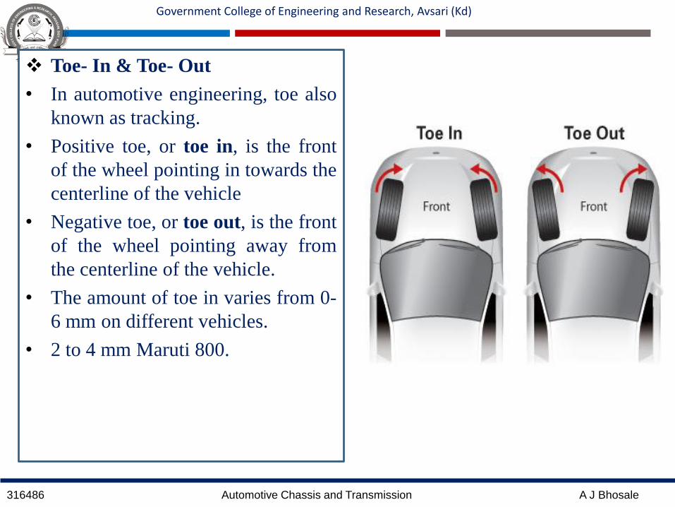
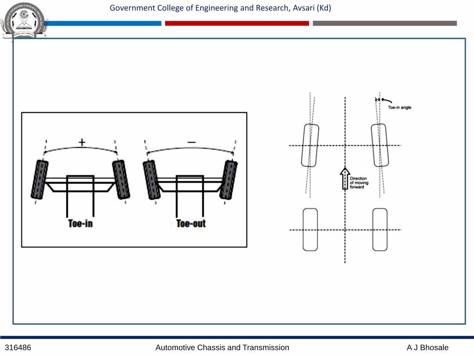
Toe- In & Toe- Out
• In automotive engineering, toe also
known as tracking.
• Positive toe, or toe in, is the front
of the wheel pointing in towards the
centerline of the vehicle
• Negative toe, or toe out, is the front
of the wheel pointing away from
the centerline of the vehicle.
• The amount of toe in varies from 0-
6 mm on different vehicles.
• 2 to 4 mm Maruti 800.
316486 Automotive Chassis and Transmission A J Bhosale
Government College of Engineering and Research, Avsari (Kd)
316486 Automotive Chassis and Transmission A J Bhosale
Government College of Engineering and Research, Avsari (Kd)
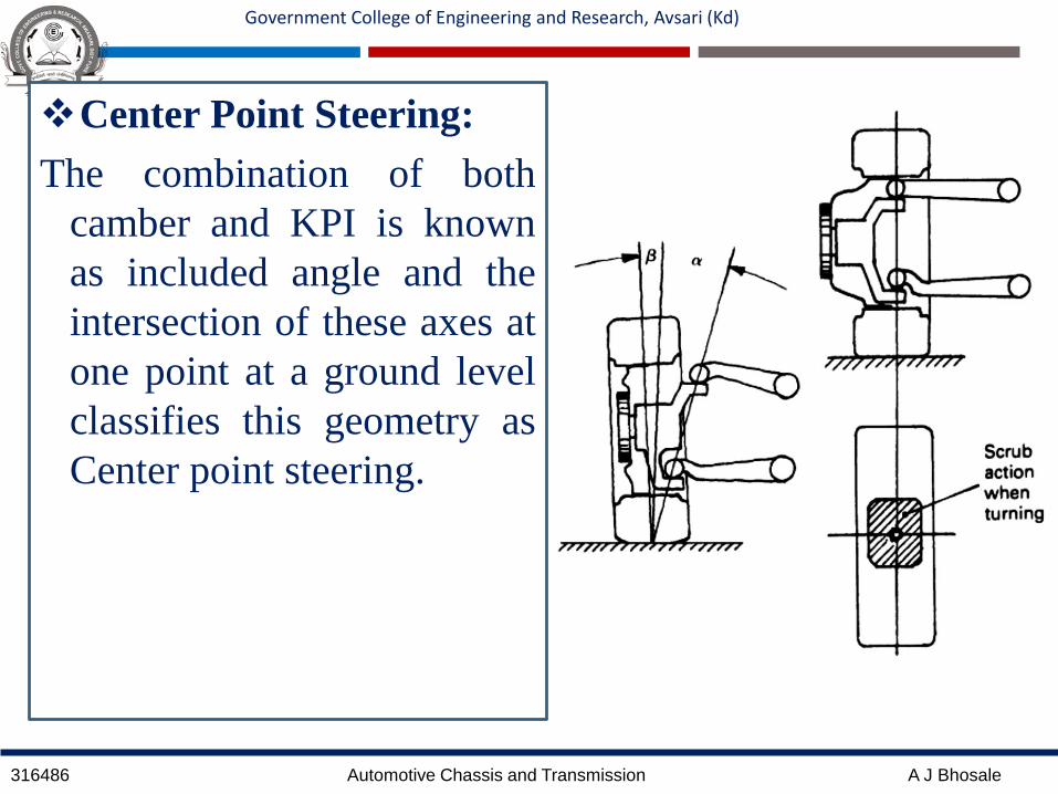
Center Point Steering:
The combination of both
camber and KPI is known
as included angle and the
intersection of these axes at
one point at a ground level
classifies this geometry as
Center point steering.

316486 Automotive Chassis and Transmission A J Bhosale
Government College of Engineering and Research, Avsari (Kd)
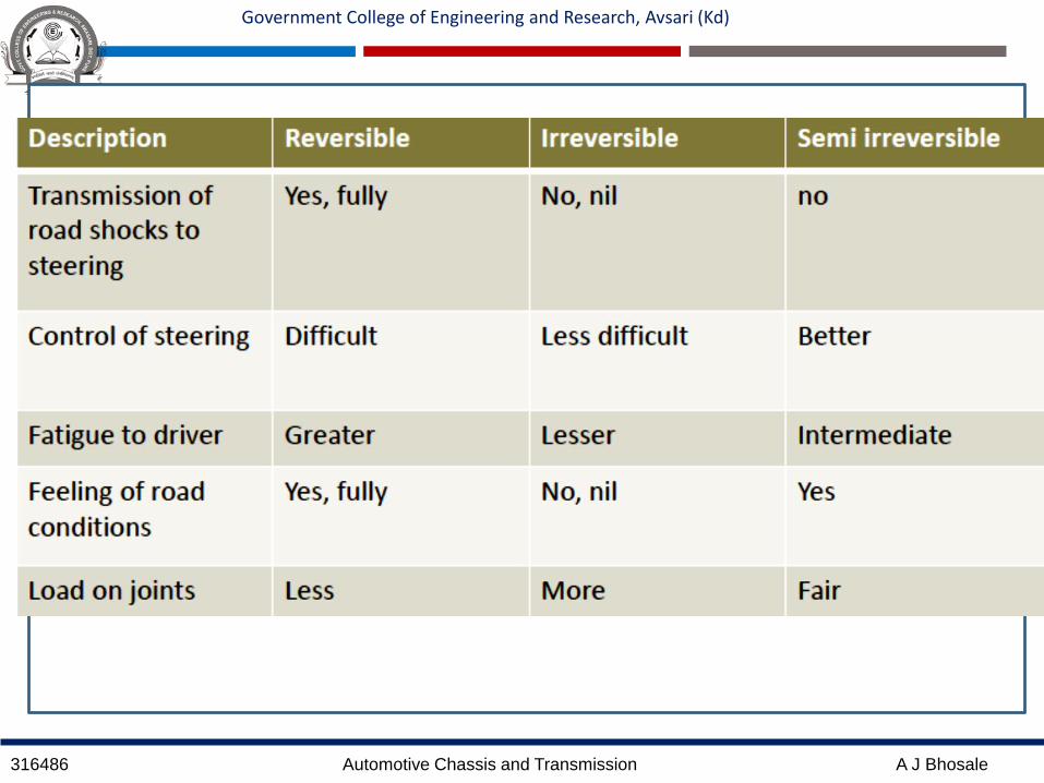
Reversible, Irreversible and Semi-reversible Steering
When an effort (i/p) is applied on the steering wheel
which causes the road wheels to swivel(o/p).
If this action is reversed by swiveling the road wheels
(i/p), the steering wheel can be turned(o/p) then the
system is known as reversible steering.
In an irreversible steering it is not possible to turn the
steering wheel by swiveling the road wheels.
A compromise made between the short coming of the
two systems results in semi reversible steering
316486 Automotive Chassis and Transmission A J Bhosale
Government College of Engineering and Research, Avsari (Kd)
316486 Automotive Chassis and Transmission A J Bhosale
Government College of Engineering and Research, Avsari (Kd)
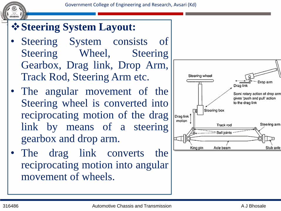
Steering System Layout:
• Steering System consists ofSteering Wheel, SteeringGearbox, Drag link, Drop Arm,Track Rod, Steering Arm etc.
• The angular movement of theSteering wheel is converted intoreciprocating motion of the draglink by means of a steeringgearbox and drop arm.
• The drag link converts thereciprocating motion into angularmovement of wheels.
316486 Automotive Chassis and Transmission A J Bhosale
Government College of Engineering and Research, Avsari (Kd)
Steering Gear:
• Generally, steering gear has mainly two functions: it produces a gearreduction between the input steering wheel and the output drop arm(pitmanarm), it redirects the input to output axis of rotation through the right angle.
• Simply, the steering gear is a device for converting the rotary motion of thesteering wheel into straight line motion of the linkage with a mechanicaladvantage.
• If the steering wheel is connected directly to the steering linkage it wouldrequire a great effort to move the front wheels.
• Therefore, to assist the driver, a reduction system is used having a steeringratio (the ratio between the turn of the steering wheel in degrees orhandlebars and the turn of the wheels in degrees ) between 12:1 to 28:1 the
actual value depending upon the type and weight of the vehicle.

316486 Automotive Chassis and Transmission A J Bhosale
Government College of Engineering and Research, Avsari (Kd)
• A higher steering ratio means that you have toturn the steering wheel more, to get the wheelsturning, but it will be easier to turn the steeringwheel.
• A lower steering ratio means that you have toturn the steering wheel less, to get the wheelsturning, but it will be harder to turn the steeringwheel.
• Larger and heavier vehicles like trucks willoften have a higher steering ratio, which willmake the steering wheel easier to turn.
• In normal and lighter cars, the wheels are easierto turn, so the steering ratio doesn't have to be ashigh.
• In race cars the ratio becomes really low,because you want the vehicle to respond a lotquicker than in normal cars.

316486 Automotive Chassis and Transmission A J Bhosale
Government College of Engineering and Research, Avsari (Kd)
• Generally, the stub axles must be capable of
twisting through a maximum steering angle of
40° either side of straight ahead position.
• Therefore lock to lock drop arm angular
displacement amounts to 80°
With 12:1 Gear reduction steering wheel turns
= (80*12)/360 = 2.66 turns
With 28:1 Gear reduction steering wheel turns
= (80*28)/360 = 6.22 turns
316486 Automotive Chassis and Transmission A J Bhosale
Government College of Engineering and Research, Avsari (Kd)
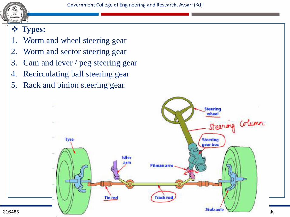
Types:
1. Worm and wheel steering gear
2. Worm and sector steering gear
3. Cam and lever / peg steering gear
4. Recirculating ball steering gear
5. Rack and pinion steering gear.
316486 Automotive Chassis and Transmission A J Bhosale
Government College of Engineering and Research, Avsari (Kd)
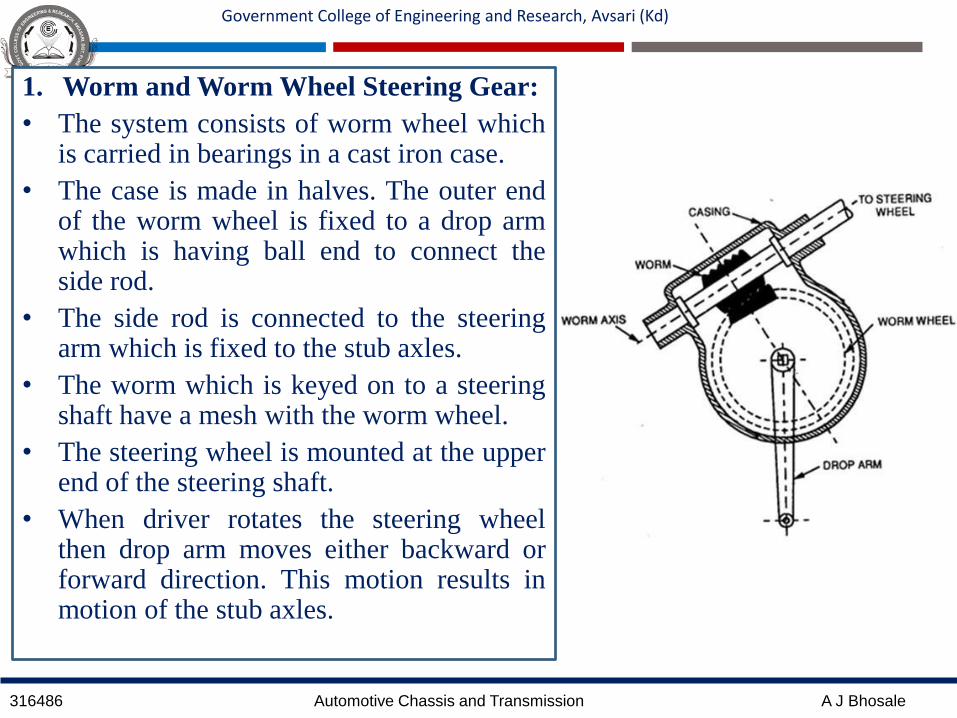
1. Worm and Worm Wheel Steering Gear:
• The system consists of worm wheel whichis carried in bearings in a cast iron case.
• The case is made in halves. The outer endof the worm wheel is fixed to a drop armwhich is having ball end to connect theside rod.
• The side rod is connected to the steeringarm which is fixed to the stub axles.
• The worm which is keyed on to a steeringshaft have a mesh with the worm wheel.
• The steering wheel is mounted at the upperend of the steering shaft.
• When driver rotates the steering wheelthen drop arm moves either backward orforward direction. This motion results inmotion of the stub axles.
316486 Automotive Chassis and Transmission A J Bhosale
Government College of Engineering and Research, Avsari (Kd)
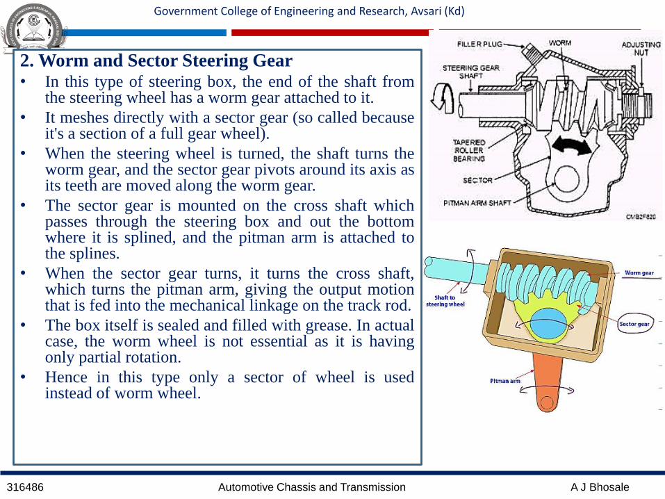
2. Worm and Sector Steering Gear• In this type of steering box, the end of the shaft from
the steering wheel has a worm gear attached to it.
• It meshes directly with a sector gear (so called becauseit's a section of a full gear wheel).
• When the steering wheel is turned, the shaft turns theworm gear, and the sector gear pivots around its axis asits teeth are moved along the worm gear.
• The sector gear is mounted on the cross shaft whichpasses through the steering box and out the bottomwhere it is splined, and the pitman arm is attached tothe splines.
• When the sector gear turns, it turns the cross shaft,which turns the pitman arm, giving the output motionthat is fed into the mechanical linkage on the track rod.
• The box itself is sealed and filled with grease. In actualcase, the worm wheel is not essential as it is havingonly partial rotation.
• Hence in this type only a sector of wheel is usedinstead of worm wheel.

316486 Automotive Chassis and Transmission A J Bhosale
Government College of Engineering and Research, Avsari (Kd)

316486 Automotive Chassis and Transmission A J Bhosale
Government College of Engineering and Research, Avsari (Kd)
3. Cam and Peg/Lever Steering Gear:
• Here a helical groove is formed at the bottom end of the steering wheel
shaft.
• The helical groove engages the projected pin of the drop arm spindle lever.
• The drop-arm is made rigid with the lever/peg by a splined spindle. The to
and fro motion is obtained at the drop-arm when the steering wheel shaft is
turned. This motion results the turning of the stub axles.
• The end play of the steering wheel shaft can be adjusted by putting a
suitable washer at the lock nut.
• The meshing of the projected pin in helical groove is also adjusted by a
screw provided at the end of the lever spindle. In the recent models, the
projected pin is made in the form of a roller.
• The projected pin may be one or two in number, accordingly they are
referred as cam and single lever or double lever steering gear mechanism

316486 Automotive Chassis and Transmission A J Bhosale
Government College of Engineering and Research, Avsari (Kd)

316486 Automotive Chassis and Transmission A J Bhosale
Government College of Engineering and Research, Avsari (Kd)
Screw and Nut Steering Gear
• The screw and nut steering gear is the
foundation for all types other steering gear
reduction mechanisms.
• A screw and nut combination mechanism
which increases both force and movement
ratios.
• A small input effort applied to the end of
perpendicular lever fixed to the screw is
capable of moving much larger load axially
along the screw provided that nut is
prevented from rotating.

316486 Automotive Chassis and Transmission A J Bhosale
Government College of Engineering and Research, Avsari (Kd)
4. Reciprocating Ball type Steering Gear:
• It consists of a worm at the end of steering rod. A nut is mounted on the worm with two
sets of balls in the grooves of the worm, in between the nut and, the worm.
• The balls reduce the friction during the movement of the nut on the worm. The nut has
a number of teeth on outside, which mesh with the teeth on a worm wheel sector, on
which is further mounted the drop arm.
• When the steering wheel is turned, the balls in the worm roll in the grooves and cause
the nut to travel along the length of the worm.
• The balls, which are in 2 sets, are recirculated through the guides. The movement of
the nut causes the wheel sector to turn at an angle and actuate the link rod through the
drop arm, resulting in the desired steering of the wheels.
• The end play of the worm can be adjusted by means of the adjuster nut provided.
• To compensate for the wear of the teeth on the nut and the worm, the two have to be
brought nearer bodily.
• To achieve this, the teeth on the nut are made tapered in the plane perpendicular to the
plane of Figure.

316486 Automotive Chassis and Transmission A J Bhosale
Government College of Engineering and Research, Avsari (Kd)

316486 Automotive Chassis and Transmission A J Bhosale
Government College of Engineering and Research, Avsari (Kd)
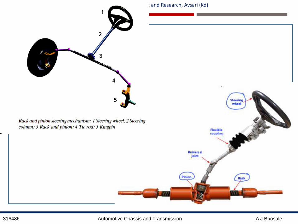
5. Rack and Pinion Steering Gear:
This type of steering gear is used on light
vehicles like cars and in power assist steering.
It is simple light and responsive.
It occupies very small space and uses lesser
number of linkage components compared to
the worm and wheel type of gear.
The rotary motion of the steering wheel is
transmitted to the pinion of the steering gear
through universal joints
The pinion is in mesh with a rack.
The circular motion of the pinion is
transferred into the linear rack movement,
which is further relayed through the ball
joints and tie rods to the stub axles for the
wheels to be steered.
316486 Automotive Chassis and Transmission A J Bhosale
Government College of Engineering and Research, Avsari (Kd)
316486 Automotive Chassis and Transmission A J Bhosale
Government College of Engineering and Research, Avsari (Kd)
Power Steering:
The main objective of power steering is to reduce the driver’s effort in
steering.
This system may employ electrical devices and hydraulic pressure.
Power steering is basically power assisted steering in which an arrangement
to boost the steering wheel turning is provided.

316486 Automotive Chassis and Transmission A J Bhosale
Government College of Engineering and Research, Avsari (Kd)
Hydraulic Power Assisted Steering Gear:
When the rack-and-pinion is in a power-steering system, the rack has a slightly
different design.
Part of the rack contains a cylinder with a piston in the middle.
The piston is connected to the rack. There are two fluid ports, one on either
side of the piston.
Supplying higher-pressure fluid to one side of the piston forces the piston to
move which in turn moves the rack so providing power assist.

316486 Automotive Chassis and Transmission A J Bhosale
Government College of Engineering and Research, Avsari (Kd)
Electric Power Assist Steering Gear:
It uses an electric motor to reduce effort byproviding steering assist to the driver of avehicle.
Sensors detect the motion and torque ofthe steering column, and a computermodule applies assistive torque via anelectric motor coupled directly to eitherthe steering gear or steering column.
This allows varying amounts of assistanceto be applied depending on drivingconditions.
The system allows engineers to tailorsteering-gear response to variable-rate andvariable-damping suspension systemsachieving an ideal blend of ride, handling,and steering for each vehicle.
In the event of component failure, amechanical linkage such as a rack andpinion serves as a back-up in a mannersimilar to that of hydraulic systems.

316486 Automotive Chassis and Transmission A J Bhosale
Government College of Engineering and Research, Avsari (Kd)

316486 Automotive Chassis and Transmission A J Bhosale
Government College of Engineering and Research, Avsari (Kd)
Electro-hydraulic Power Assist Steering Gear:
Electro-hydraulic power steering systems, sometimes abbreviated EHPS,and also sometimes called "hybrid" systems, use the same hydraulic assisttechnology as standard systems, but the hydraulic pressure is provided by apump driven by an electric motor instead of being belt-driven by the engine.
By providing power assist via hydraulic pressure, this system delivers anaturally smooth steering feel and, thanks to the flexibility of controlallowed by electric power, offers more precise steering powercharacteristics. It also improves fuel economy since the electric poweredpump operates only when steering assist is needed

316486 Automotive Chassis and Transmission A J Bhosale
Government College of Engineering and Research, Avsari (Kd)
Related Documents