Basic Civil Engineering Unit I Surveying: Objects – types- classification- Principles – Measurements of distances – levelling Civil Engineering Materials: Bricks – Stones – sand – Cement – Concrete – Steel Sections

Welcome message from author
This document is posted to help you gain knowledge. Please leave a comment to let me know what you think about it! Share it to your friends and learn new things together.
Transcript

Basic Civil EngineeringUnit I
Surveying:
Objects – types- classification- Principles –
Measurements of distances – levelling
Civil Engineering Materials:
Bricks – Stones – sand – Cement – Concrete – Steel
Sections

Surveying•It is defined as the process of measuring horizontal
distances, vertical distances and included angles to
determine the location of points on, above or below the
earth surfaces.
• The term surveying is the representation of surface
features in a horizontal plane.
• The process of determining the relative heights in the
vertical plane is referred as levelling.

SURVEYING PlanMapElevation or Section LEVELLING

Objectives of Surveying
• The data obtained by surveying are used to prepare
the plan or map showing the ground features.
• When the area surveyed is small and the scale
to which its result plotted is large, then it is
known as Plan
• When the area surveyed is large and the scale
to which its result plotted is small, then it is
called as a Map
•Setting out of any engineering work like buildings,
roads, railway tracks, bridges and dams involves
surveying.

Main divisions of surveying
Types of Surveying
•Plane surveying
• Geodetic surveying (or) Trigonometrical Surveying
Concept:
Since the shape of the earth is spheroidal, the line connecting any two points on the earth surface is not a straight line, but a curve.
When the surveys extend over a large areas or when the accuracy required is great, the curvature of earth has also to be taken into account.
For small distances the difference and the subtended chord

Plane Surveying
• The surveying where the effect of curvature of
earth is neglected and earth’s surface is treated as
plane, is called surveying.
• The degree of accuracy in this type of surveying is
comparatively low.
• Generally when the surveying is conducted over the
area less than 260 Sq.Km., they are treated as plane
surveying.

Geodetic Surveying
• The effect of curvature is taken into account.
• It is also known as “Trigonometrical Surveying”.
• It is a special branch of surveying in which
measurements are taken with high precision
instruments.
• Calculations are also made with help of spherical
trigonometry.
• It is generally adopted by the Great Trigonometrical
Survey Department of India”. (GTS).
Classification of surveying
• Land Surveying• Marine or Navigation or Hydrographic Surveying• Astronomical Survey.Land Surveying: Land survey is a one, in which the relative points or objects on the earth’s surface is determined.Marine or Navigational or Hydrographic Survey:Marine surveying is one in which the relative position of objects under water is determined. Astronomical Surveying: It is one in which observations are made to locate the heavenly bodies such as sun, moon and stars.

Classification of Land surveying
Topographical Survey: • It is used for determining the natural and artificial features of the country such as rivers, lakes, hills and canals.Cadastral Survey: • It is used to locate additional details such as boundaries of fields of fields, houses and other properties.City Survey: • It is used for town planning schemes such as laying out plots, constructing streets, laying water supply and sewer lines.• Engineering Survey : It is used to collect data for design and construction of Engineering works such as roads, railways, bridges dams etc.,

Principles of Surveying
Principle 1:
• A number of control points are fixed in the area
concerned by adopting very accurate and precise
methods.
• The lines joining these control points will be control
lines.
• Other measurements are made to locate points inside
these control lines.

Principles of Surveying
Principle 1:
• The main triangles and traverses are divided into smaller
ones by using less rigorous methods.
• By doing so, accumulation of errors is avoided and any local
error can be easily identified.
• If survey work is started from a part (smaller triangle or
traverse) and proceeded to whole there are chances of errors
getting multiplied at every stage.
• Hence any survey work should be from whole to part
and not from part to whole.

Principles of Surveying
Principle 2: • New points should be fixed by at least two independent measurements.
l1 l2
P Q
R
Figure 1
P Q
R
θ1 θ2
Figure 2
P Q
R
θ1
Figure 3
l1
Principles of Surveying
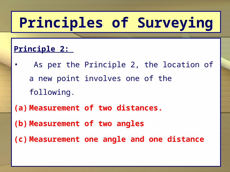
Principle 2:
• As per the Principle 2, the location of a new
point involves one of the following.
(a) Measurement of two distances.
(b) Measurement of two angles
(c) Measurement one angle and one distance

Classification of surveying
Classification of surveying:
• Chain Surveying
• Compass Surveying
• Theodolite surveying
• Plane Surveying
• Techeometric Surveying
Chain Surveying - Principle
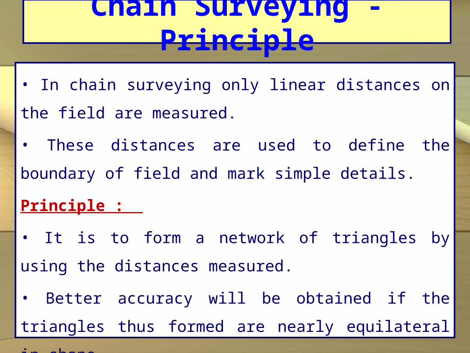
• In chain surveying only linear distances on the field
are measured.
• These distances are used to define the boundary of
field and mark simple details.
Principle :
• It is to form a network of triangles by using the
distances measured.
• Better accuracy will be obtained if the triangles thus
formed are nearly equilateral in shape.

Chain Surveying
Instruments for Measuring Horizontal Distance1.Surveyor’s Chain2.Steel Band3.Tape4.Arrows (Chain Pins)Instruments for Making Stations on the Ground1.Ranging Rods2.Offset Rods3.Cross Staff4.Plumb Bob5.Pegs and Wooden Hammer
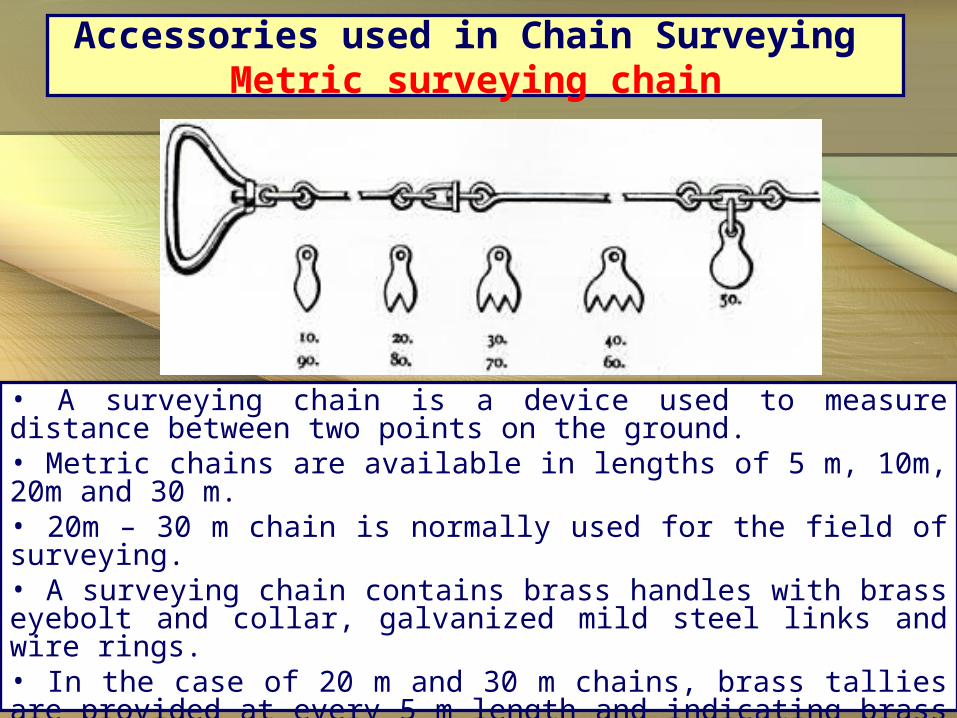
Accessories used in Chain Surveying Metric surveying chain
• A surveying chain is a device used to measure distance between two points on the ground.• Metric chains are available in lengths of 5 m, 10m, 20m and 30 m.• 20m – 30 m chain is normally used for the field of surveying.• A surveying chain contains brass handles with brass eyebolt and collar, galvanized mild steel links and wire rings.• In the case of 20 m and 30 m chains, brass tallies are provided at every 5 m length and indicating brass wire rings are attached at every meter length except where tallies are provided.

Accessories used in Chain Surveying Chain Pins
• Chain pins or arrows are used with the
chain for marking each chain length on
the ground.
• The arrow is driven into the ground at
the end of each chain length is measured.
•The overall length is 400 mm and
thickness is 4mm.
•The arrow has a circular eye at the one
end is pointed at the other end .

Accessories used in Chain Surveying Pegs
• Wooden pegs of 15cm length and 3 cm square in
section are used to establish the station points or the end
points of a line on the ground.
• They are tapered one end and are driven into the
ground by using a wooden hammer.
• About 4 cm is left projecting above the ground.
Accessories used in Chain Surveying Measuring Tape
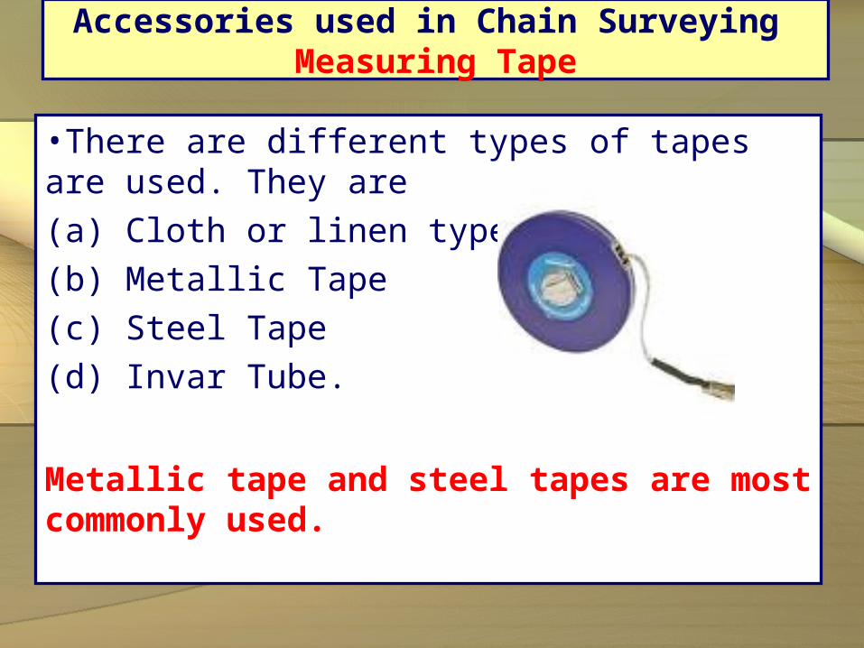
•There are different types of tapes are used. They are(a) Cloth or linen type(b) Metallic Tape(c) Steel Tape(d) Invar Tube.
Metallic tape and steel tapes are most commonly used.
Accessories used in Chain Surveying Ranging Rod
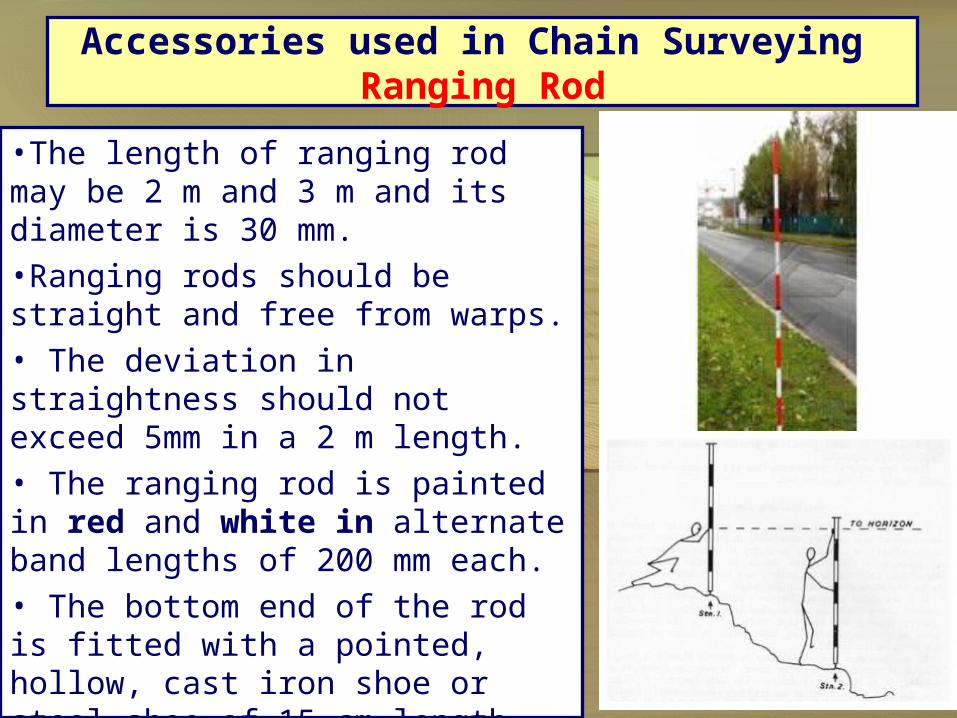
•The length of ranging rod may be 2 m and 3 m and its diameter is 30 mm.•Ranging rods should be straight and free from warps.• The deviation in straightness should not exceed 5mm in a 2 m length.• The ranging rod is painted in red and white in alternate band lengths of 200 mm each.• The bottom end of the rod is fitted with a pointed, hollow, cast iron shoe or steel shoe of 15 cm length.
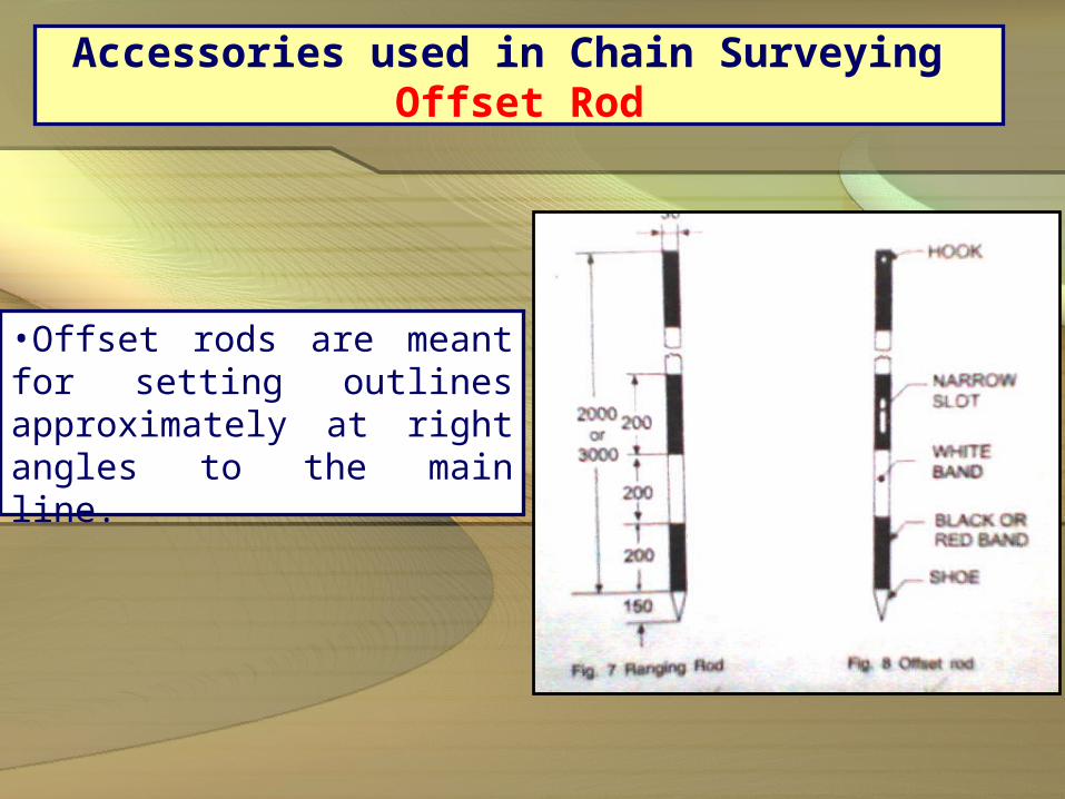
Accessories used in Chain Surveying Offset Rod
•Offset rods are meant for setting outlines approximately at right angles to the main line.

Accessories used in Chain Surveying Cross Staff
• It is used to set out right angles in chain surveying• It consists of four metal arms vertical slits mounted on a pole.• Two opposite slits are positioned along the length of a line (Main Line)• A line perpendicular to the main line is formed or sighted through the other two slits

Accessories used in Chain Surveying Plumb Bob
• It consists of a solid conical piece
and a string attached to it at its
centre.
•It is used to test the verticality of
the ranging rods and to transfer the
points to the ground.
• Plumb bob is used while doing
chain surveying on sloping ground.

Advantages and disadvantages of chain surveying
Advantages:•It is simple• It does not require any costly equipment• It is adopted for preparing plans for small areaDisadvantages:• It cannot be used for large areas• It cannot be used in thick bushy areas with ups and downs.• Chain surveying is not always accurate.

Terminology:Survey StationMain StationTie Station (or) Subsidiary StationSurvey LinesBase LineCheck Line (or) Proof LineTie Line (or) Subsidiary LineOffset

Chaining a Survey Line:i) Chaining along Flat Groundii) Chaining along Sloping Ground
Direct (or) Stepping MethodIndirect Method – By measuring the sloping
length and Difference in Elevations

Direct (or) Stepping Method

Indirect Method – By Measuring the Sloping Length and Difference in
Elevation

Measurement of Angles

1. Closed Traverse
2. Open Traverse
Traverse Survey

1. Deflection Angle Method2. Included Angle Method
Methods of Measurement of Angles

• In traverse surveying, when the direction of survey lines measured by compass and the length of survey lines measured with tape or chain, then it is said to be compass surveying.
• Compass is one of the instruments used to measure the angles.
Compass:1. Prismatic Compass2. Surveyor’s Compass
Compass Surveying

Compass Surveying – Prismatic Compass

Surveyor's Compass

Prismatic CompassDescription:•A magnetic needle is balanced over a pivot in a circular box of 85 mm to 110 mm in diameter.•An agate cap keeps the aluminium ring stable.• The box is covered by a glass lid.• Object vane and eye vane are provided at diametrically opposite ends.• Eye vane caries a reflecting prism which can be raised or lowered as desired.• A vertical horse hair or fine wire is provided at the middle of the object vane.• The graduations in the aluminium ring are made in the clockwise direction starting with 0o at South and 180o at North with inverted markings.
Prismatic Compass
Description:
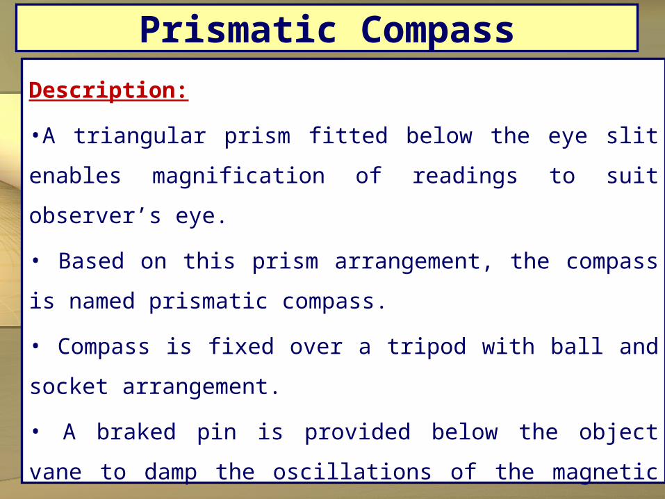
•A triangular prism fitted below the eye slit enables
magnification of readings to suit observer’s eye.
• Based on this prism arrangement, the compass is
named prismatic compass.
• Compass is fixed over a tripod with ball and socket
arrangement.
• A braked pin is provided below the object vane to
damp the oscillations of the magnetic needle while
taking readings.

Prismatic CompassWorking Principle:• The magnetic field aligns itself with the magnetic meridian (N-S direction)• The line of sight is actually the line joining the object vane and eye vane• The angle between the N-S direction and the line of sight is observed in the compass• This angle is actually the angle between N-S direction and the line on the ground• This angle made by the line with the N-S direction is called the bearing of the line.• Compass is used to measure the bearing of the different lines from which the angles included between the adjacent lines are computed.

• Classification of Bearing1. True Bearing2. Magnetic Bearing
Designation of Bearings1. Whole Circle Bearing (W.C.B)2. Reduced Bearing (R.B) or Quadrantal Bearing (Q.B)3. Fore Bearing (F.B)4. Back Bearing (B.B)
Bearings & Angles

Definitions
Magnetic Bearing:• It is the angle between the magnetic meridian and the line.• The angle is always measured in the clockwise direction• It is the direction shown by a freely suspended magnetic needle• The magnetic meridian is also called bearing.True Bearing: • True bearing of a line is the angle between the true meridian and the line.• The angle is always measured in the anticlockwise direction.• The true meridian is the line joining the geographical north and south bearings.

Definitions
Whole Circle Bearing: • The bearing of lines measured from the North is called Whole Circle Bearing.• The angle is reckoned in the clockwise direction from 0o coinciding with the north.
Quadrant Bearing:• The whole circle is divided into four quadrants.• The bearing is expressed with N or S as prefix and E or W as suffix.• Quadrant Bearing is also known as Reduced Bearing.

Definitions
Fore Bearing and Back bearing:• Every line has two bearing namely fore bearing and back back bearing• Fore bearing is the bearing taken in the direction of surveying and Back bearing is the bearing taken in the reverse direction.• The difference between the fore bearing and the back bearing should be 180o.• It means that one or both stations of the line are subjected to local attraction.• Thus, local attraction is the influence caused on the measured bearings of lines due to the presence of materials like railway track, current carrying wires or cables, etc.,
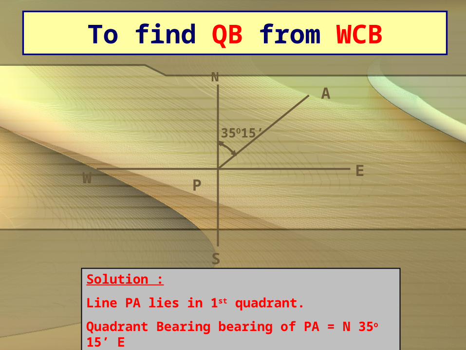
To find QB from WCB
N
EW
S
A
35O15’
P
Solution :
Line PA lies in 1st quadrant.
Quadrant Bearing bearing of PA = N 35o 15’ E

To find QB from WCB
130O0’
E
S
N
W
B
P
50O
Solution :
Line PB lies in 2nd quadrant.
Quadrant Bearing bearing of PB = S 50o 00’ E

To find QB from WCB
P
210O15’
S
W E
N
C
30O15’
Solution :
Line PC lies in 3rd quadrant.
Quadrant Bearing bearing of PC = S 30o 15’ W

To find QB from WCB
PW
N
S
E
D69O15’
290O45’ Solution :
Line PD lies in 4th quadrant.
Quadrant Bearing bearing of PD = N 69o 15’ W

To find Whole Circle Bearing from QB
(i) WCB = PA –N 15o E(ii) WCB = PB – S 25o 45’ E(iii) WCB = PC – S 45o 30’ W(iv) WCB = PD – N 10o W
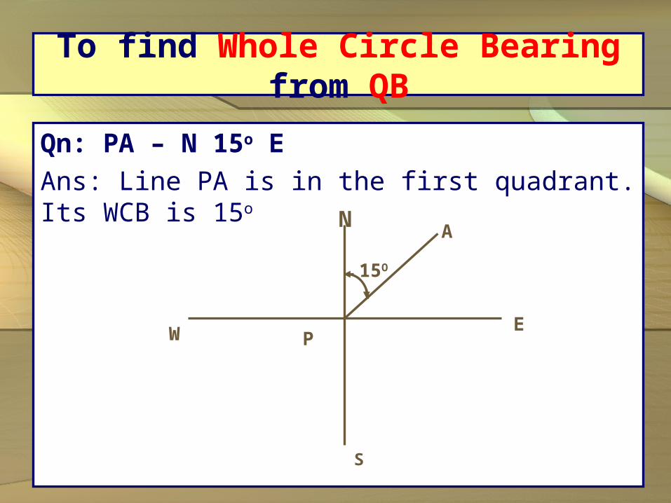
To find Whole Circle Bearing from QB
Qn: PA – N 15o EAns: Line PA is in the first quadrant. Its WCB is 15o
N
E
S
W
15O
P
A

To find Whole Circle Bearing from QB
Qn: PB – S 25o 45’ ELine PB is in second quadrant. Its WCB is 180o00’-25o45’ = 154o15’N
E
S
W P
B
154O15’

To find Whole Circle Bearing from QB
Qn: PC – S 45o 30’WLine PC is third quadrant. Its WCB is 180o00’+45o30’ = 225o30’N
E
S
W P
B225o30’
c

To find Whole Circle Bearing from QB
Qn: PD – N 10o WLine PD is in fourth quadrant. Its WCB is360o00’-10o00’= 350o00’ N
E
S
W P
350o00’
D

To find Back Bearing from Fore Bearing
Qn: Fore bearing of Line PQ is 38o15’, find Back bearing.
Back Bearing =218o15’
38o15’
P
Q

To find Back Bearing from Fore Bearing
Qn: Fore bearing of Line RS is 210o15’ find the back bearing.
210o15’
Back Bearing =30o30’
R
S

• Theodolite is a prices instrument used for measuring horizontal and vertical angles in surveying, including determining differences in elevation, extending survey lines, locating points on a survey line, setting out curves etc.
• Transit Theodolite• Non-transit Theodolite
Theodolite Surveying

1. Telescope
2. Vertical Circle
3. Altitude Bubble
4. Upper Plate (or)
Vernier Plate
5. Lower Plate (or)
Scale Plate (or)
Main Plate
6. Plate Levels (or)
Plate Bubbles
Transit Theodolite
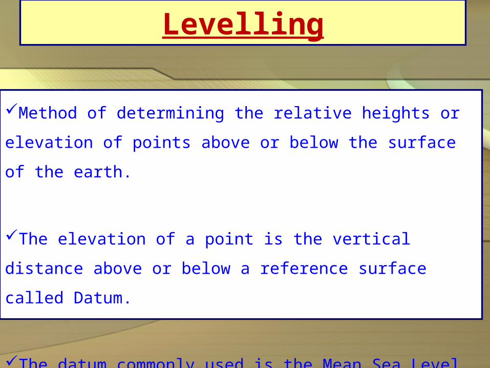
Levelling
Method of determining the relative heights or elevation
of points above or below the surface of the earth.
The elevation of a point is the vertical distance above
or below a reference surface called Datum.
The datum commonly used is the Mean Sea Level
(M.S.L)
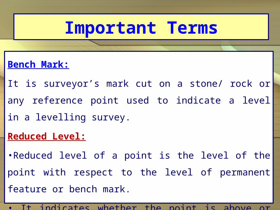
Important Terms
Bench Mark:
It is surveyor’s mark cut on a stone/ rock or any
reference point used to indicate a level in a levelling
survey.
Reduced Level:
•Reduced level of a point is the level of the point with
respect to the level of permanent feature or bench
mark.
• It indicates whether the point is above or below the
reference point.

Terminology

Instruments used in levelling
Instruments used in levelling are,
(i)Levelling instrument
(ii)Levelling staff
Levelling Instrument :
• Simplest form of levelling instrument is dumpy
level.
• The different parts of levelling instrument are,
(a) Telescope (b) Eye-piece (c) focussing knob
(d) level tube (e) cross bubble (f) foot screws
(g) levelling head (h) diaphragm (i) ray shade

Dumpy Level
Related Documents


