UNIT I Inside the PC Introduction: Evolution of Computer – Block diagram of Pentium - Inside the Pentium – Parts -Mother board, chipset, expansion slots, memory, Power supply, drives and connectors Systems: Desktop, Lap Top, Specification and features - Comparison table. Server system – IBM server families, Sun Server, Intel processor etc. - Workstation. Mother Board: Evolution – Different forms of mother boards - Riser Architectures. Intel, AMD and VIA motherboards. Chipsets: Introduction – 945 chipset. Bus Standards: Introduction – ISA Bus – PCI Bus – PCI Express, USB, and High speed Bus, – Pin details and Architecture. Bios-setup: Standard CMOS setup, Advanced BIOS setup, Power management, advanced chipset features, PC Bios communication – upgrading BIOS, Flash, and BIOS - setup. Processors: Introduction – Pentium IV, Hyper threading, dual core technology, Core2Duo technology –– AMD Series, Athlon 2000, Xeon processor. Comparison tables. Pentium Pin details, Itanium Processor - Pentium packaging styles.

Welcome message from author
This document is posted to help you gain knowledge. Please leave a comment to let me know what you think about it! Share it to your friends and learn new things together.
Transcript
UNIT I
Inside the PC
Introduction: Evolution of Computer – Block diagram of Pentium - Inside the
Pentium – Parts -Mother board, chipset, expansion slots, memory, Power
supply, drives and connectors Systems: Desktop, Lap Top, Specification
and features - Comparison table. Server system – IBM server families, Sun
Server, Intel processor etc. - Workstation.
Mother Board: Evolution – Different forms of mother boards - Riser
Architectures. Intel, AMD and VIA motherboards.
Chipsets: Introduction – 945 chipset.
Bus Standards: Introduction – ISA Bus – PCI Bus – PCI Express, USB, and
High speed Bus, – Pin details and Architecture.
Bios-setup: Standard CMOS setup, Advanced BIOS setup, Power
management, advanced chipset features, PC Bios communication –
upgrading BIOS, Flash, and BIOS - setup.
Processors: Introduction – Pentium IV, Hyper threading, dual core
technology, Core2Duo technology –– AMD Series, Athlon 2000, Xeon
processor. Comparison tables. Pentium Pin details, Itanium Processor -
Pentium packaging styles.
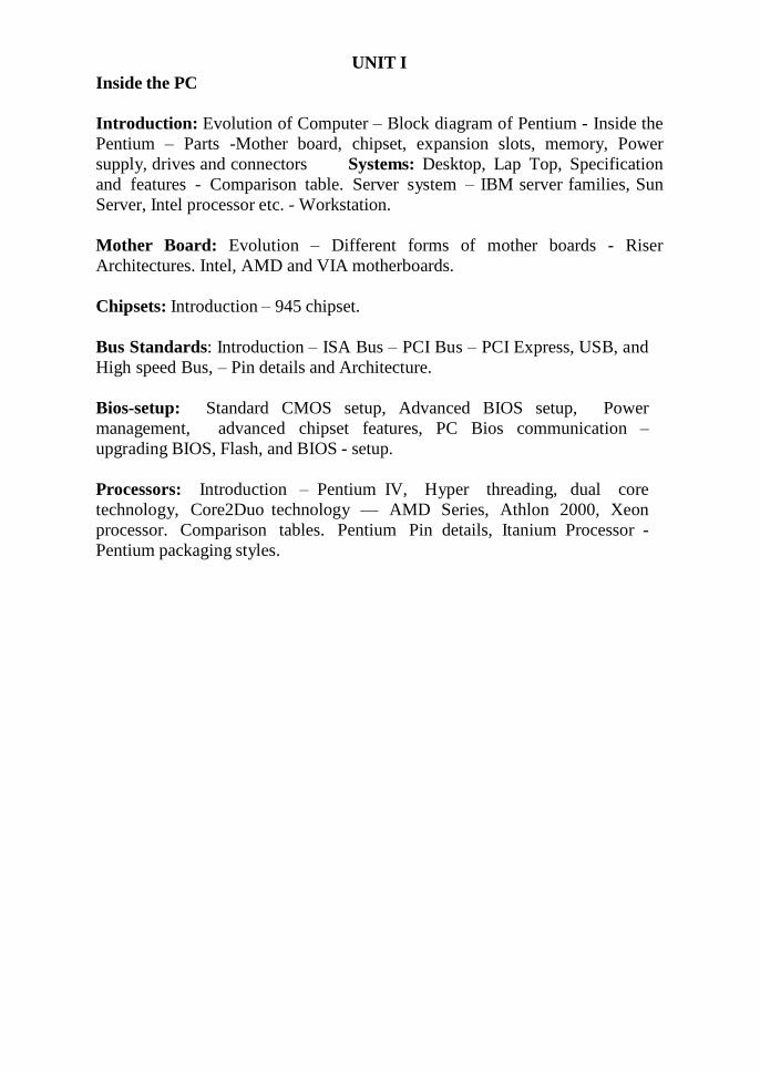
1642 – Blaise Pascal introduces the digital adding machine.
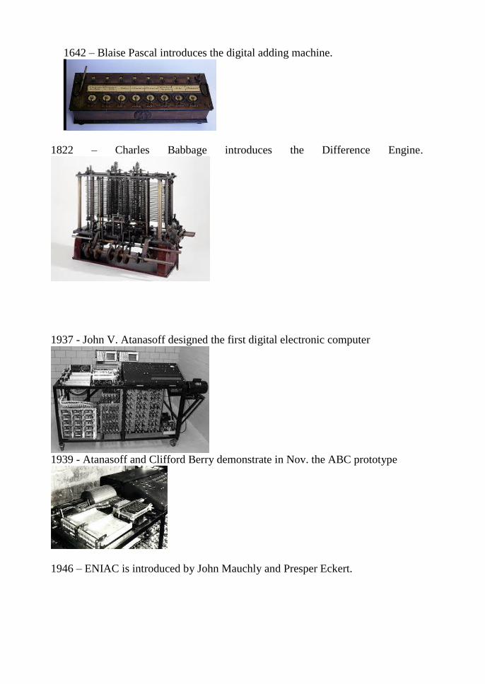
1822 – Charles Babbage introduces the Difference Engine.
1937 - John V. Atanasoff designed the first digital electronic computer
1939 - Atanasoff and Clifford Berry demonstrate in Nov. the ABC prototype
1946 – ENIAC is introduced by John Mauchly and Presper Eckert.
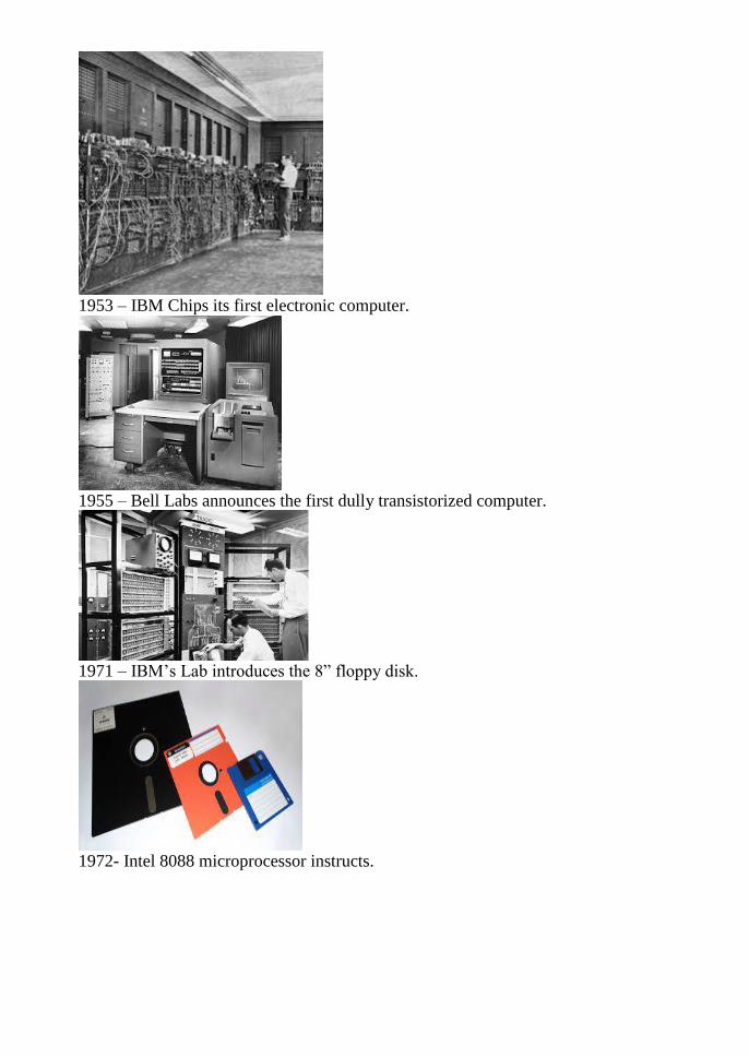
1953 – IBM Chips its first electronic computer.
1955 – Bell Labs announces the first dully transistorized computer.
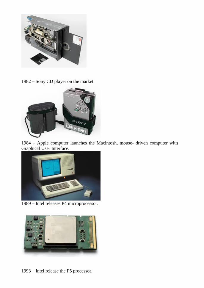
1971 – IBM‘s Lab introduces the 8‖ floppy disk.
1972- Intel 8088 microprocessor instructs.
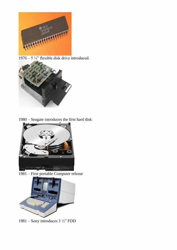
1976 – 5 ¼‖ flexible disk drive introduced.
1980 – Seagate introduces the first hard disk
1981 – First portable Computer release
1981 – Sony introduces 3 ½‖ FDD
1982 – Sony CD player on the market.
1984 – Apple computer launches the Macintosh, mouse- driven computer with
Graphical User Interface.
1989 – Intel releases P4 microprocessor.
1993 – Intel release the P5 processor.
1995 – Intel releases the Pentium Pro Processor.
1995 – Microsoft releases Windows 95
1998 – Microsoft releases Windows 98
1999 – Intel releases the PIII, AMD introduces the Athlon.
2000 – Microsoft releases Windows 2000
2001 – Microsoft releases Windows XP
2002 – Microsoft releases Windows XP
2018 – Processor
Ever since Intel announced its first Core i9 processor for desktops last year, it‘s
only been a matter of time until the company brought that branding to laptops,
too. Today, Intel is announcing its first Core i9 chip for laptops, with what it
claims is ―the best gaming and creation laptop processor Intel has ever built.‖
ARCHITECTURE OF PENTIUM
The architecture of Pentium Microprocessor:
The Pentium family of processors, which has its roots in the Intel486(TM)
processor, uses the Intel486 instruction set (with a few additional
instructions).The term ''Pentium processor'' refers to a family of microprocessors
that share a common architecture and instruction set. The first Pentium processors
(the P5 variety) were introduced in 1993.
This 5.0-V processor was fabricated in 0.8-micron bipolar complementary metal
oxide semiconductor (BiCMOS) technology. The P5 processor runs at a clock
frequency of either 60 or 66 MHz and has 3.1 million transistors.
The Intel Pentium processor, like its predecessor the Intel486 microprocessor, is
fully software compatible with the installed base of over 100 million compatible
Intel architecture systems.
In addition, the Intel Pentium processor
provides new levels of performance to
new and existing software through a
reimplementation of the Intel 32-bit
instruction set architecture using the
latest, most advanced, design techniques.
Optimized, dual execution units provide
one-clock execution for "core"
instructions, while advanced technology,
such as superscalar architecture, branch prediction, and execution pipelining,
enables multiple instructions to execute in parallel with high efficiency.
The application of this advanced technology in the Intel Pentium processor brings
"state of the art" performance and capability to existing Intel architecture software
as well as new and advanced applications. The Pentium processor has two
primary operating modes and a "system management mode.
Protected Mode
This is the native state of the microprocessor. In this mode all instructions and
architectural features are available, providing the highest performance and
capability. This is the recommended mode that all new applications and operating
systems should target. Among the capabilities of protected mode is the ability to
directly execute "real-address mode" 8086 software in a protected, multi-tasking
environment. This feature is known as Virtual-8086 "mode" (or"V86 mode").
Virtual-8086 "mode" however, is not actually a processor "mode, ―it is in fact an
attribute which can be enabled for any task while in protected mode.
Real-Address Mode (also called "real mode")
This mode provides the programming environment of the Intel 8086 processor,
with a few extensions (such as the ability to break out of this mode). Reset
initialization places the processor in real mode where, with a single instruction, it
can switch to protected mode.
System Management Mode
The Pentium microprocessor also provides support for System Management
microprocessors, beginning with the Intel386 SL processor, which provides an
operating-system and application independent and transparent mechanism to
implement system power management and OEM differentiation features. SIMMs
entered through activation of an external interrupt pin (SMI#), which switches the
CPU to a separate address space while saving the entire context of the CPU.
SMM-specific code may then be executed transparently. The operation is reversed
upon returning.
Superscalar Execution: The Intel486 processor can execute only one instruction
at a time. With superscalar execution, the Pentium processor can sometimes
execute two instructions simultaneously.
Pipeline Architecture: Like the Intel486 processor, the Pentium processor
executes instructions in five stages. This staging, or pipelining, allows the
processor to overlap multiple instructions so that it takes less time to execute two
instructions in a row. Because of its superscalar architecture, the Pentium
processor has two independent processor pipelines.
64-Bit Bus: With its 64-bit-wide external data bus (in contrast to the
Intel486processor's 32-bit- wide external bus) the Pentium processor can handle
up to twice the data load of the Intel486 processor at the same clock frequency.
Floating-Point Optimization: The Pentium processor executes individual
instructions faster through execution pipelining, which allows multiple floating-
point instructions to be executed at the same time.
Pentium Extensions: The Pentium processor has fewer instruction set extensions
than the Intel486 processors. The Pentium processor also has a setoff extension
for multiprocessor (MP) operation. This makes a computer with multiple Pentium
processors possible.
A Pentium system, with its wide, fast buses, advanced write-backache/memory
subsystem, and powerful processor, will deliver more power for today‘s software
applications, and also optimize the performance of advanced 32-bit operating
systems (such as Windows 95) and 32-bit software applications.
Chipset
In a computer system, a chipset is a set of electronic components in an integrated
circuit known as a "Data Flow Management System" that manages the data flow
between the processor, memory and peripherals. ... Chipsets are usually designed
to work with a specific family of microprocessors.
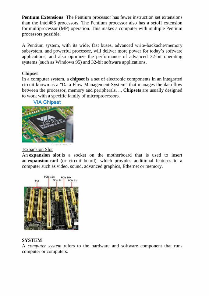
Expansion Slot
An expansion slot is a socket on the motherboard that is used to insert
an expansion card (or circuit board), which provides additional features to a
computer such as video, sound, advanced graphics, Ethernet or memory.
SYSTEM
A computer system refers to the hardware and software component that runs
computer or computers.

Operating systems:
An operating system (commonly abbreviated OS and O/S) is an interface between
hardware and applications. It is responsible for the management and coordination
of activities and the sharing of the limited resources of the computer. The
operating system acts as a host for applications that are run on the machine.
Operating systems can be classified as follows:
multi-user:
Allows two or more users to run programs at the same time. Some operating
systems permit hundreds or even thousands of concurrent users.
multiprocessing:
Supports running a program on more than one CPU.
multitasking:
Allows more than one program to run concurrently.
multithreading:
Allows different parts of a single program to run concurrently.
real time:
Responds to input instantly. General-purpose operating systems, such as DOS and
UNIX, are not real-time.
DESKTOP
A computer designed to fit comfortably on top of a desk, typically with the
monitor sitting on top of the computer. Desktop model computers are broad and
low, whereas tower model computers are narrow and tall. Because of their shape,
desktop model computers are generally limited to three internal mass storage
devices. Desktop models designed to be very small are sometimes referred to as
slim line models.
LAP TOP SYSTEMS
A laptop computer is a personal computer designed for mobile use that is small
enough to sit on one's lap
A laptop integrates all of the typical components of a desktop computer, including
a display, a keyboard a pointing device (a touchpad, also known as atrackpad, or a
pointing stick) and a battery into a single portable unit.
The rechargeable battery is charged from an AC/DC adapter and has enough
capacity to power the laptop for several hours.
A laptop is usually shaped like a large notebook with thickness of 0.7–1.5inches
(18–38 mm) and dimensions ranging from 10x8 inches (27x22cm, 13"display) to
15x11 inches (39x28cm, 17" display) and up.
Modern laptops weigh 3 to 12 pounds (1.4 to 5.4 kg), and some older laptops
were even heavier.
Most laptops are designed in the flip form factor to protect the screen and the
keyboard when closed.
COMPONENTS:
Motherboard: Laptop motherboards are highly make- and model-specific, and
do not conform to a desktop form factor. Unlike a desktop board that usually has
several slots for expansion cards (3 to 7 are common), a board for a small, highly
integrated laptop may have no expansion slots at all, with all the functionality
implemented on the motherboard itself; the only expansion possible in this case is
via an external port such as USB. Other boards may have one or more standard or
proprietary expansion slots. Several other functions (storage controllers,
networking, sound card and external ports) are implemented on the motherboard.
Central processing unit (CPU) Laptop CPUs have advanced power-saving
features and produce less heathen desktop processors, but are not as powerful.
There is a wide range of CPUsdesigned for laptops available from Intel (Pentium
M, Celeron M, Intel Core and Core2 Duo), AMD (Athlo, Turion 64, and
Sempron,) VIA Technologies, Transmit and others. On the non-x86 architectures,
Motorola and IBM produced the chips for the former PowerPC based Apple
laptops (iBook and PowerBook). Some laptops have removable CPUs, although
support by the motherboard may be restricted to the specific models. In other
laptops the CPU is soldered on the motherboard and isnon-replaceable.
Memory (RAM) SO-DIMM memory modules that are usually found in laptops
are about half the size of desktop DIMMs. They may be accessible from the
bottom of the laptop for ease of upgrading, or placed in locations not intended for
user replacement such as between the keyboard and the motherboard.
Expansion cards A PC Card (formerly PCMCIA) or Express Card bay for
expansion cards is often present on laptops to allow adding and removing
functionality, even when the laptop is powered on. Some subsystems (such as Wi-
Fi or a cellular modem) can be implemented as replaceable internal expansion
cards, usually accessible under an access cover on the bottom of the laptop. Two
popular standards for such cards are MiniPCI and its successor, the PCI Express
Mini.
Power supply laptops are powered by an internal rechargeable battery that is
charged using an external power supply. The power supply can charge the battery
and power the laptop simultaneously; when the battery is fully charged, the laptop
continues to run on AC power. The charger adds about 400 grams (1 lb) to the
overall "transport weight" of the notebook.
Battery Current laptops utilize lithium ion batteries, with more recent models using the
new lithium polymer technology. These two technologies have largely replaced
the older nickel metal-hydride batteries. Typical battery life for standard laptops is
two to five hours of light-duty use, but may drop to as little as one hour when
doing power-intensive tasks.

Batteries' performance gradually decreases with time, leading to an eventual
replacement in one to three years, depending on the charging and discharging
pattern. This large-capacity main battery should not be confused with the much
smaller battery nearly all computers use to run the realtimeclock and to store the
BIOS configuration in the CMOS memory when the computer is off. Lithium-Ion
batteries do not have a memory effect as older batteries may have. The memory
effect happens when one does not use a battery toots fullest extent, then recharges
the battery.
Video display controller On standard laptops video controller is usually integrated into the chipset. This
tends to limit the use of laptops for gaming and entertainment, two fields which
have constantly escalating hardware demands [32]. Higher-end laptops and
desktop replacements in particular often come with dedicated graphics processors
on the motherboard or as an internal expansion card. These mobile graphics
processors are comparable in performance to mainstream desktop graphic
accelerator boards.
Display Most modern laptops feature 12 inch (30 cm) or larger color active matrix
displays with resolutions of 1024×768 pixels and above. Many current models use
screens with higher resolution than typical for desktop PCs (for example,
the1440×900 resolution of a 15" Macbook Pro can be found on 19" widescreen
desktop monitors).
Removable media drives DVD/CD reader/writer drive is standard. CD drives are becoming rare, whileBlu-
Ray is not yet common on notebooks [35]. Many ultra portables and netbooks
either move the removable media drive into the docking station or exclude it
altogether.
Internal storage
– Hard disks are physically smaller—2.5 inch (60 mm) or 1.8 inch (46 mm) —
compared to desktop 3.5 inch (90 mm) drives. Some new laptops (usually ultra
portables) employ more expensive, but faster, lighter and power efficient Flash
memory-based SSDs instead. Currently, 250 to 320 Gb sizes are common for
laptop hard disks (64 to 128 Gb for SSDs).
Input
A pointing stick, touchpad or both are used to control the position of the cursor on
the screen, and an integrated keyboard is used for typing. External keyboard and
mouse may be connected using USB or PS/2 (if present).

Ports
Several USB ports, an external monitor port (VGA or DVI), audio in/out, and an
Ethernet network port are found on most laptops. Less common are legacy ports
such as a PS/2 keyboard/mouse port, serial port or a parallel port. S-video or
composite video ports are more common on consumer-oriented notebooks.
Advantages
Portability
Usually the first feature mentioned in any comparison of laptop versus desktop
PCs. Portability means that a laptop can be used in many places—not only at
home and at the office, but also during commuting and flights, in coffee shops, in
lecture halls and libraries, at clients' location or at a meeting room, etc.
The portability feature offers several distinct advantages:
Getting more done
– using a laptop in places where a desktop PC can't be used, and at times that
would otherwise be wasted. For example, an office worker managing his e-mails
during an hour-long commute by train, or a student doing her homework at the
university coffee shop during a break between lectures.
Immediacy
– Carrying a laptop means having instant access to various information, personal
and work files. Immediacy allows better collaboration between coworkers or
students, as a laptop can be flipped open to present a problem or a solution
anytime, anywhere.
Up-to-date information
– If a person has more than one desktop PC, a problem of synchronization arises:
changes made on one computer are not automatically propagated to the others.
There are ways to resolve this problem, including physical transfer of updated
files (using a USB stick or CDs) or using synchronization software over the
Internet. However, using a single laptop at both locations avoids the problem
entirely, as the files exist in a single location and are always up-to-date.
Connectivity
– A proliferation of Wi-Fi wireless networks and cellular broadband data services
(HSDPA, EVDO and others) combined with a near ubiquitous support by laptops
means that a laptop can have easy Internet and local network connectivity while
remaining mobile. Wi-Fi networks and laptop programs are especially widespread
at university campuses.

Other advantages of laptops include:
Size
– laptops are smaller than standard PCs. This is beneficial when space isat a
premium, for example in small apartments and student dorms. When not in use, a
laptop can be closed and put away.
Low power consumption
– laptops are several times more power-efficient than desktops. A typical laptop
uses 20-90 W, compared to 100-800 W for desktops. This could be particularly
beneficial for businesses (which run hundreds of personal computers, multiplying
the potential savings) and homes where there is a computer running 24/7 (such as
a home media server, print server, etc.)
Quiet
– laptops are often quieter than desktops, due both to better components (quieter,
slower 2.5-inch hard drives) and to less heat production leading to use of fewer
and slower cooling fans.
Battery – a charged laptop can run several hours in case of a power outage and is
not affected by short power interruptions and brownouts. A desktop PC needs a
UPS to handle short interruptions, brownouts and spikes; achieving on-battery
time of more than 20-30 minutes for a desktop PC requires a large and expensive
UPS.
Disadvantages
Performance
While the performance of mainstream desktops and laptops is comparable,
laptops are significantly more expensive than desktop PCs at the same
performance level. However, for Internet browsing and typical office applications,
where the computer spends the majority of its time waiting for the next user input,
even notebook-class laptops are generally fast enough. Standard laptops are
sufficiently powerful for high-resolution movie play back, 3D gaming and video
editing and encoding. Number-crunching software (databases, math, engineering,
financial, etc.) is the area where the laptops are atthe biggest disadvantage.
Upgradability Upgradability of laptops is very limited compared to desktops,
which are thoroughly standardized. In general, hard drives and memory can be
upgraded easily. Optical drives and internal expansion cards may be upgraded if
they follow an industry standard, but all other internal components, including the
CPU and graphics, are not intended to be upgradeable. Because of their small and
flat keyboard and track pad pointing devices, prolonged use of laptops can cause
repetitive strain injury.
Usage of separate, external ergonomic keyboards and pointing devices is
recommended to prevent injury when working for long periods of time; they can
be connected to a laptop easily by USB or via a docking station. Some health
standards require ergonomic keyboards at workplaces. The integrated screen often
causes users to hunch over for a better view, which can cause neck or spinal
injuries. A larger and higher-quality external screen can be connected to almost
any laptop to alleviate that and to provide additional "screen estate" for more
productive work.
Durability Due to their portability, laptops are subject to more wear and physical
damage than desktops. Components such as screen hinges, latches, power jacks
and power cords deteriorate gradually due to ordinary use. A liquid spill onto the
keyboard, a rather minor mishap with a desktop system, can damage the internals
of a laptop and result in a costly repair.
Security Being expensive, common and portable, laptops are prized targets for
theft. The cost of the stolen business or personal data and of the resulting
problems (identity theft, credit card fraud, breach of privacy laws) can be many
times the value of the stolen laptop itself. Therefore, both physical protection of
laptops and the safeguarding of data contained on them are of the highest
importance. Most laptops have a Kensington security slot which is used to tether
the computer to a desk or other immovable object with a security cable and lock.
In addition to this, modern operating systems and third-party software offer disk
encryption functionality that renders the data on the laptop's hard drive unreadable
without a key or a passphrase.
DESKTOP VS LAPTOP
1.) Laptops are portable.
2.) Desktops still do everything a laptop does better except the portability.
Desktops are less for more power.
Server System A server is a computer provides services to other computer in the
network. In a client/server programming model, a sever is a program that awaits
and fulfills requests from client programs in other computers.
Server: It is a large computer that manages shared resources and provides a
service to the client.
Client: It is a single user PC or workstation. It sends request to the server and
receives the response from the server.
MOTHERBOARD
The motherboard is the large printed circuit board that is mounted to the bottom
of the computer's case.
Motherboards have standard mounting holes so that the same computer case can
be used with different boards.
All of the components of a computer system are connected in some way to the
motherboard.
The most common motherboard design in desktop computers today is the AT,
based on the IBM AT motherboard. A more recent motherboard specification,
ATX improves on the AT design.
In both the AT and ATX designs, the computer components included in the
motherboard are1. The microprocessor2. (Optionally) coprocessors3. Memory4.
basic input/output system (BIOS)5. Expansion slot Interconnecting circuitry
Additional components can be added to a motherboard through its expansion slot.
The electronic interface between the motherboard and the smaller boards or cards
in the expansion slots is called the bus. The image below is a typical motherboard,
the Intel D865GBF along with the documentation showing the positions of the
board's components.
Components of Motherboard Motherboard Components and Function:
Function: The motherboard is a printed circuit board (PCB) that contains and
controls the components that are responsible for processing data.
Description: The motherboard contains the CPU, memory, and basic controllers
for the system. Motherboards are often sold with a CPU. The motherboard has a
Real-time clock (RTC), ROM BIOS, CMOS RAM, RAM sockets, bus slots for
attaching devices to a bus, CPU socket(s) or slot(s), cache RAM slot or sockets,
jumpers, keyboard controller, interrupts, internal connectors, and external
connectors. The bus architecture and type of components on it determine a
computers performance. The motherboard with its ribbon cables, power supply,
CPU, and RAM is designated as a "bare bones" system.
The motherboard determines:
CPU type and speed
Chipset Type (the specialized chips that control the memory, cache, external
buses, and some peripherals)
Secondary cache type
Types of expansion slots: ISA, EISA, MCA, VESA local bus, PCI and AGP slots
Different forms of mother boards Form Factor:
The form factor of a motherboard determines the specifications for its general
shape and size. It also specifies what type of case and power supply will be
supported, the placement of mounting holes, and the physical layout and
organization of the board. Form factor is especially important if you build your
own computer systems and need to ensure that you purchase the correct case and
components.
AT & Baby AT Prior to 1997, IBM computers used large motherboards. After
that, however, the size of the motherboard was reduced and boards using the AT
(Advanced Technology) form factor was released. The AT form factor is found in
older computers (386 class or earlier). Some of the problems with this form factor
mainly arose from the physical size of the board, which is 12" wide, often causing
the board to overlap with space required for the drive bays. Following the AT
form factor, the Baby AT form factor was introduced. With the Baby AT form
factor the width of the motherboard was decreased from 12" to 8.5",limiting
problems associated with overlapping on the drive bays' turf. Baby AT became
popular and was designed for peripheral devices — such as the keyboard, mouse,
and video — to be contained on circuit boards that were connected by way of
expansion slots on the motherboard. Baby AT was not without problems however.
Computer memory itself advanced, and the Baby AT form factor had memory
sockets at the front of the motherboard. As processors became larger, the Baby
AT form factor did not allow for space to use a combination of processor, heat
sink, and fan. The ATX form factor was then designed to overcome these issues
ATX With the need for a more integrated form factor which defined standard
locations for the keyboard, mouse, I/O, and video connectors, in the mid 1990's
the ATX form factor was introduced. The ATX form factor brought about many
chances in the computer. Since the expansion slots were put onto separate riser
cards that plugged into the motherboard, the overall size of the computer and its
case was reduced. The ATX form factor specified changes to the motherboard,
along with the case and power supply. Some of the design specification
improvements of the ATX form factor included a single 20-pin connector for the
power supply, a power supply to blow air into the case instead of out for better air
flow, less overlap between the motherboard and drive bays, and integrated I/O
Port connectors soldered directly onto the motherboard. The ATX form factor was
an overall better design for upgrading.
micro-ATX Micro ATX followed the ATX form factor and offered the same
benefits but improved the overall system design costs through a reduction in the
physical size of the motherboard. This was done by reducing the number of I/O
slots supported on the board. The microATX form factor also provided more I/O
space at the rear and reduced emissions from using integrated I/O connectors.

LPXWhite ATX is the most well-known and used form factor, there is also a
nonstandard proprietary form factor which falls under the name of LPX, and
Mini-LPX. The LPX form factor is found in low-profile cases (desktop model as
opposed to atower or mini-tower) with a riser card arrangement for expansion
cards where expansion boards run parallel to the motherboard. While this allows
for smaller cases it also limits the number of expansion slots available. Most LPX
motherboards have sound and video integrated onto the motherboard. While this
can make for a low-cost and space saving product they are generally difficult to
repair due to a lack of space and overall non-standardization. The LPX form
factor is not suited to upgrading and offer poor cooling.
NLXBoards based on the NLX form factor hit the market in the late 1990's. This
"updated LPX" form factor offered support for larger memory modules, tower
cases, AGP video support and reduced cable length. In addition, motherboards are
easier to remove. The NLX form factor, unlike LPX is an actual standard which
means there is more component options for upgrading and repair. Many systems
that were formerly designed to fit the LPX form factor are moving over to NLX.
The NLX form factor is well-suited to mass-market retail PCs.
BTX The BTX, or Balanced Technology Extended form factor, unlike its
predecessors is not an evolution of a previous form factor but a total break away
from the popular and dominating ATX form factor. BTX was developed to take
advantage of technologies such as Serial ATA, USB 2.0, and PCI Express.
Changes to the layoutwith the BTX form factor include better component
placement for back panel I/O controllers and it is smaller than microATX
systems. The BTX form factor provides the industry push to tower size systems
with an increased number of system slots. One of the most talked about features
of the BTX form factor is that it uses in-line airflow. In the BTX form factor the
memory slots and expansion slots have switched places, allowing the main
components (processor, chipset, and graphics controller) to use the same airflow
which reduces the number of fans needed in the system; thereby reducing noise.
To assist in noise reduction BTX system level acoustic shave been improved by a
reduced air turbulence within the in-line airflow system. Initially there will be
three motherboards offered in BTX form factor. The first, picoBTX will offer four
mounting holes and one expansion slot, while microBTX will hold seven
mounting holes and four expansion slots, and lastly, regularBTX will offer 10
mounting holes and seven expansion slots. The new BTX form factor design is
incompatible with ATX, with the exception of being able to use an ATXpower
supply with BTX boards. Today the industry accepts the ATX form factor as the
standard, however legacy AT systems are still widely in use. Since the BTX form
factor design is incompatible with ATX, only time will tell if it will overtake
ATX as the industry standard.
ATX form factor The Intel Advanced/ML motherboard, launched in 1996, was
designed to solve issues of space and airflow that the Pentium II and AGP
graphics cards had caused the preceding LPX form factor. As the first major
innovation in form factors in years, it marked the beginning of a new era in
motherboard design. Its size and layout are completely different to the BAT
format, following a new scheme known asATX. The dimensions of a standard
ATX board are 12in wide by 9.6in long; the miniATX variant is typically of the
order 11.2in by 8.2in.The ATX design gets round the space and airflow problems
by moving the CPU socket and the voltage regulator to the right-hand side of the
expansion bus. Room is made for the CPU by making the card slightly wider, and
shrinking or integrating components such as the Flash BIOS, I/O logic and
keyboard controller. This means the board need only be half as deep as a full size
Baby AT, and there's noob struction whatsoever to the six expansion slots (two
ISA, one ISA/PCI, three PCI).
ATX Form Factor An important innovation was the new specification of power
supply for the ATX that can be powered on or off by a signal from the
motherboard. At a time when energy conservation was becoming a major issue,
this allows notebook-style power management and software-controlled shutdown
and power-up. A 3.3V output is also provided directly from the power supply.
Accessibility of the processor and memory modules is improved dramatically, and
relocation of the peripheral connectors allows shorter cables to be used. This also
helps reduce electromagnetic interference. The ATX power supply has a side vent
that blows air from the outside directly across the processor and memory
modules, allowing passive heatsinks to be used in most cases, thereby reducing
system noise. Mini-ATX is simply a smaller version of a full-sized ATX board.
On both designs, parallel, serial, PS/2 keyboard and mouse ports are located on a
double height I/O shield at the rear. Being soldered directly onto the board
generally means no need for cable interconnects to the on-board I/O ports. A
consequence of this, however, is that the ATX needs a newly designed case, with
correctly positioned cut-outs for the ports, and neither ATX no Mini-ATX boards
can be used in AT-style cases.
Riser Architectures In the late 1990s, the PC industry developed a need for a
riser architecture that would contribute towards reduced overall system costs and
at the same time increase the flexibility of the system manufacturing process. The
Audio/Modem Riser (AMR) specification, introduced in the summer of 1998, was
the beginning ofa new riser architecture approach. AMR had the capability to
support both audio and modem functions. However, it did have some
shortcomings, which were identified after the release of the specification. These
shortcomings included the lack of Plug and Play (PnP) support, as well as the
consumption of a PCI connector location. Consequently, new riser architecture
specifications were defined which combine more functions onto a single card.
These new riser architectures combine audio, modem, broadband technologies,
and LAN interfaces onto a single card. They continue to give motherboard OEMs
the flexibility to create a generic motherboard for a variety of customers. The riser
card allows OEMs and system integrators to provide a customised solution for
each customer's needs. Two of the most recentriser architecture specifications
include CNR and ACR.
CNR - Communications and Networking Riser
Intel's CNR (Communication and Networking Riser) specification defines a
hardware scalable OEM motherboard riser and interface that supports the audio,
modem, and LAN interfaces of core logic chipsets. The main objective of this
specification is to reduce the baseline implementation cost of features that are
widely used in the "Connected PC", while also addressing specific functional
limitations of today's audio, modem, and LAN subsystems. PC users' demand for
feature-rich PCs, combined with the industry's current trend towards lower cost,
mandates higher levels of integration at all levels of the PC platform.
Motherboard integration of communication technologies has been problematic to
date, for a variety of reasons, including FCC and international telecom
certification processes, motherboard space, and other manufacturer specific
requirements. Motherboard integration of the audio, modem, and LAN
subsystems is also problematic, due to the potential for increased noise, which in-
turn degrades the performance of each system. The CNR specifically addresses
these problems by physically separating these noise-sensitive systems from the
noisy environment of the motherboard. With a standard riser solution, as defined
in this specification, the system manufacturer is free to implement the audio,
modem, and/or LAN subsystems at a lower bill of materials (BOM) cost than
would be possible by deploying the same functions in industry-standard
expansion slots or in a proprietary method. With the added flexibility that
hardware scalability brings, a system manufacturer has several motherboard
acceleration options available, all stemming from the baseline CNR interface.
The CNR Specification supports the five interfaces:
AC97 Interface - Supports audio and modem functions on the CNR card
LAN Connect Interface (LCI) - Provides 10/100 LAN or Home Phone line
Networking capabilities for Intel chipset based solutions
Interface (MII) - Provides 10/100 LAN or Home Phone line Networking
capabilities for CNR platforms using the MII Interface
Universal Serial Bus (USB) - Supports new or emerging technologies such asx
DSL or wireless
System Management Bus (SM Bus) - Provides Plug and Play (PnP) functionality
on the CNR card. Each CNR card can utilise a maximum of four interfaces by
choosing the specific LAN interface to support.
ACR - Advanced Communications Riser The rival ACR (Advanced
Communications Riser) specification is supported by an alliance of leading
computing and communication companies, whose founders include 3COM,
AMD, VIA Technologies and Lucent Technologies. Like CNR, it defines a form
factor and interfaces for multiple and varied communications and audio
subsystem designs in desktop OEM personal computers. Building on first
generation PC motherboard riser architecture, ACR expands the riser card
definition beyond the limitation of audio and modem codecs, while maintaining
backward compatibility with legacy riser designs through an industry standard
connector scheme. The ACR interface combines several existing communications
buses, and introduces new and advanced communications buses answering
industry demand for low-cost, high-performance communications
peripherals.ACR supports modem, audio, LAN, and xDSL. Pins are reserved for
future wireless bus support. Beyond the limitations of first generation riser
specifications, the ACR specification enables riser-based broadband
communications, networking peripheral and audio subsystem designs. ACR
accomplishes this in an open standards context. Like the original AMR
Specification, the ACR Specification was designed to occupy or replace an
existing PCI connector slot. This effectively reduces the number of available PCI
slots by one, regardless of whether the ACR connector is used. Though this may
be acceptable in a larger form factor motherboard, such as ATX, the loss of a PCI
connector in a micro ATX or Flex ATX motherboard – which often provide as
few as two expansion slots - may well be viewed as an unacceptable trade-off.
The CNR specification overcomes this issue by implementing a shared slot
strategy, much like the shared ISA /PCI slots of the recent past. In a shared slot
strategy, both the CNR and PCI connectors effectively use the same I/O bracket
space. Unlike the ACR architecture, when the system integrator chooses not to
use a CNR card, the shared PCI slot is still available. Although the two
specifications both offer similar functionality, the way inwhich they are
implemented are quite dissimilar.
In addition to the PCI connector/shared slot issue, the principal differences are as
follows:
ACR is backwards compatible with AMR, CNR isn't
xDSL technologies via its Integrated Packet Bus (IPB)technology; CNR provides
such support via the well-established USB interface ACR provides for concurrent
support for LCI (LAN Connect Interface) and MII(Media Independent Interface)
LAN interfaces; CNR supports either, but notboth at the same time
The ACR Specification has already reserved pins for a future wireless interface;
the CNR specification has the pins available but will only define them when the
wireless market has become more mature. Ultimately, motherboard manufacturers
are going to have to decide whether the ACR specification's additional features
are worth the extra cost

CHIPSET
A number of integrated circuits designed to perform one or more related
functions. For example, one chipset may provide the basic functions of modem
while another provides the CPU functions for a computer.
Newer chipsets generally include functions provided by two or more older
chipsets. In some cases, older chipsets that required two or more physical chips
can be replaced with a chipset on one chip.
The term is often used to refer to the core functionality of a motherboard.
NORTHBRIDGE
The Northbridge, also known as a memory controller hub (MCH) or an integrated
memory controller (IMC) in Intel systems (AMD, VIA, SiS and others usually use
'north bridge'), is one of the two chips in the core logic chipset on a PC
motherboard, the other being the south bridge.
Separating the chipset into the north bridge and south bridge is common, although
there are rare instances where these two chips have been combined onto one die
when design complexity and fabrication processes permit it.
SOUTHBRIDGE
The Southbridge, also known as an I/O Controller Hub (ICH) or a Platform
Controller Hub (PCH) in Intel systems (AMD, VIA, SiS and others usually use'
south bridge'), is a chip that implements the "slower" capabilities of the
motherboard in a north bridge/south bridge chipset computer architecture.
The south bridge can usually be distinguished from the north bridge by not being
directly connected to the CPU. Rather, the north bridge ties the south bridge to the
CPU.
Chipset Characteristics The characteristics of a chipset can be broken down into
six categories: host, memory, interfaces, arbitration, south bridge support, and
power management. Each of these categories defines and differentiates one
chipset from another. The characteristics defined in each of these categories are as
follows:
Host This category defines the host processor to which the chipset is matched
along with its bus voltage, usually GTL+ (Gunning Transceiver Logic Plus) or
AGTL+ (Advanced Gunning Transceiver Logic Plus), and the number of
processors the chipset will support.
Memory This category defines the characteristics of the DRAM support included
in the chipset, including the DRAM refresh technique supported, the amount of
memory support (in megabits usually), the type of memory supported, and
whether memory interleave, ECC (error correcting code), or parity is supported.
Interfaces This category defines the type of PCI interface implemented and
whether the chipset is AGP compliant, supports integrated graphics
PIPE(pipelining), or SBA (side band addressing).
Arbitration This category defines the method used by the chipset to arbitrate
between different bus speeds and interfaces. The two most common arbitration
methods are MTT (multi transaction timer) and DIA (dynamic intelligent arbiter).
South bridge support All intel chipsets and most of the chipsets for all other
manufacturers are two processor sets. In these sets the north bridge is the main
chip and handles CPU and memory interfaces among other tasks, while the south
bridge (or the second chip ) handles such things as the USB and IDE interfaces,
the RTC (real time clock),and support for serial and parallel ports.
Power management All intel chipsets support both the SMM (system
management mode) and ACPI (advanced configuration and power interface
power management standards.
Bios-setup Introduction to the BIOS:BIOS stand for Basic Input / Output
System and are software that manages hardware and allows the operating system
to talk to the various components. The BIOS is also responsible for allowing you
to control your computer's hardware settings, for booting up the machine when
you turn on the power or hit the reset button and various other system functions.
The term BIOS is typically used to refer to the system BIOS, however, various
other components such as video adapters and hard drives can have their own
BIOSes hardwired to them. During the rest of this section, we will be discussing
the system BIOS. The BIOS software lives on a ROM IC on the motherboard
known asa Complementary Metal Oxide Semiconductor (CMOS). People often
incorrectly refer to the BIOS setup utility as CMOS, however, CMOS is the name
of the physical location that the BIOS settings are stored in.
Basic CMOS Settings:
Printer Parallel Port
Unidirectional - -directional - Two
directional communication. Used by HP printers.
ECP (Extended Capability Port) - Same as Bi-directional but uses a DMA to
bypass processor and speed up transfer.
EPP (Enhanced Parallel Port) - Same as bi-directional and offers an extended
control code set.
COM/Serial Port
Memory Address - Each COM port requires a unique memory address.
IRQ - Every COM port requires a unique IRQ to talk to the CPU.
COM1 = IRQ4 and 03F8
COM2 = IRQ3 and 02F8

Hard Drives
Size - The Size is automatically detected by the computer.
Primary Master/Secondary Slave
Each hard drive has a controller built in the drive that controls the drive.
If two drives were on the same channel the adapter could get confused.
By setting one as a master it tells it which is in charge. BIOS services are
accessed using software interrupts, which are similar to the hardware interrupts
except that they are generated inside the processor by programs instead of being
generated outside the processor by hardware devices. BIOS routines begin when
the computer is booted and are made up of 3 main operations. Processor
manufacturers program processors to always look in the same place in the system
BIOS ROM for the start of the BIOS boot program. This is normally located at
FFFF0h - right at the end of the system memory. System is operating correctly
and will display an error message and/or output accessories of beeps known as
beep codes depending on the BIOS manufacturer. Second, is initialization in
which the BIOS looks for the video card. In particular, it looks for the video card's
built in BIOS program and runs it. The BIOS then looks for other devices' ROMs
to see if any of them have BIOSes and they are executed as well. Third, is to
initiate the boot process. The BIOS looks for boot information that is contained in
file called the master boot record (MBR) at the first sector on the disk. If it is
searching a floppy disk, it looks at the same address on the floppy disk for a
volume boot sector. Once an acceptable boot record is found the operating system
is loaded which takes over control of the computer.
BIOS
Services BIOS:
ROM-BIOS is a set of programs built into the computer that perform the most
basic, low level and intimate control and supervision operations for the computer.
The basic purpose of the ROM-BIOS is to take care of the immediate needs of the
computer‘s hardware and to isolate all other programs from the details of how the
hardware works. BIOS is partly software and partly hardware. It is a bridge
between the computer‘s hardware and other software.
BIOS Services ROM-BIOS is divided into three functional parts:1. Startup
routines 2.Service handling 3.Hardware interrupt handling
Startup routines: The start-up-routines get the computer going when power is
turned on. The main parts of start-up-routines are POST and initialization. POST
(Power On Self Test) routines test that the computer is in good working order.
The initialization involves routines like creating the interrupt vectors so that when
interrupts occur, the computer switches to the proper interrupt-handling routine.
Many of the parts of the computer need to have registers set, parameters loaded
and other things done to get them in their ready-to-go condition. All these are
handled by the initialization routine. The boot-strap process involves the ROM-
BIOS attempting to read a boot record from the beginning of a disk. The BIOS
first tries drive A and if that doesn‘t succeed it tries to read a boot record from the
hard disk if the computer has a hard disk, and then hands over the control of the
computer to the short program on the boot record. The boot program begins the
process of loading DOS into the computer.
Service handling: The service handling routines are there to perform work for the
programs. The programs may seek service request to clear the display screen, or
to switch the screen from text mode to graphics mode or to read information from
the disk or write information onto the printer. To carry out the service requests the
ROM-BIOS has to work directly with the computer‘s I/O devices.
Hardware interrupt handling: The hardware interrupt handling part takes care
of the independent needs of the PC hardware. It operates separately, but in co-
operation with the service handling portion. When a key is pressed on the
keyboard, the keyboard raises an interrupt. The hardware interrupt routines
service the interrupt and keep ready the character pressed. When out programs
send a request to display the character, the service routine passes the request to
the hardware interrupt handling routine. The character is then displayed. ROM
BIOS services are organized in groups with each group having its own dedicated
interrupt.
BIOS set up Access
How to access your BIOS set up:
Depending on your computer model, the way you will access your BIOS set up
menu will differ. Here is a list of the most common models used and the access
key used for this process.
ACER
You can make use of the DEL or F2 keys after switching on your system.
When using Acer Altos 600 server, the BIOS set up can be accessed by pressing
the CTRL+ALT+ESC keys.
COMPAQ
Ensure that the cursor in the upper right corner of your screen is blinking before
pressing the F10 key.
Previous versions of Compaq will make use of the F1, F2, F10 or DEL keys to
grant access to your BIOS set up menu.

DELL
After switching on your computer, let the DELL logo appear before pressing
theF2 key until Entering Setup is displayed on the screen.
Previous versions of DELL might require to press CTRL+ALT+ENTER to access
the BIOS set up menu.
The DELL laptops will use the Fn+ESC or Fn+F1 keys to access the BIOS setup.
GATEWAY
When switching on your computer, press the F1 key until the BIOS screen shows
up.
Previous versions of Gateway will make use of the F2 key to display the BIOS set
up screen.
HEWLETT-PACKARD
When switching on your computer system, press the F1 key to access the BIOSset
up screen
For those using an HP Tablet PC, you can press the F10 or F12 keys.
You can also access the BIOS set up menu by pressing the F2 or ESC keys.
IBM
When your system restarting, press the F1 key to access the BIOS set up.
Previous IBM models will require the use of the F2 key to access the BIOS setup
utility.
NEC
NEC will only use the F2 key to access the BIOS set up menu
PACKARD BELL
Packard Bell users, you can access the BIOS set up by pressing the F1, F2 or DEL
keys
SHARP
For the Sharp model, when your computer is loading, press the F2 key
For previous Sharp models, you will need to use a Setup Diagnostics Disk.
SONY
Sony users will have to press the F1, F2 or F3 key after switching on their
computer.
TOSHIBA
The Toshiba model will require its users to press the F1 or ESC key after
switching on their computer to be able to access BIOS set up menu.
Bios updates and flash bios: On most older systems, if you wanted to upgrade
the BIOS, you had to replace the ROM BIOS chip this involved physically
removing the old BIOS ROM chip and replacing it with a new ROM, containing
the new BIOS version. The potential for errors and adding new problems into the
PC, including ESD (Electrostatic Discharge), bent pins, damage to the
motherboard, and more, was very high. The danger was so great that to avoid the
stress and the problems, many people simply upgrading to a now computer. The
EEPROM (Flash ROM), flash BIOS, and flashing soon replaced the PROM and
EPROM as the primary container for BIOS programs. Some motherboards still
require the physical replacement of the BIOS PROM, but most newer platforms
support flash BIOS and flashing. Flashing is the process used to upgrade your
BIOS under the control of specialized flashing software. Any BIOS provider that
supports a flash BIOS version has flashing software and update files available
either by disk (CD-ROM or diskette) or as a downloadable module from its
website. There are really only four things you need to update your PC‘s BIOS by
flashing: a flash BIOS; the right serial number and version information, which is
used to find the right upgrade files; the flashing software; and the appropriate
flash upgrade files.
Flashing Dangers: Flashing a BIOS is an excellent way to upgrade your PC to
add new features and correct old problems, provided there are no problems while
you are doing it. Once you begin flashing your BIOS ROM, you must complete
the process, without exception. Otherwise, the result will be a corrupted and
unusable BIOS. If for any reason the flashing process is interrupted, such as
somebody trips over the PC‘s power cord or there is a power failure at that exact
moment, the probability of a corrupted BIOS chip is high. Loading the wrong
BIOS version is another way to corrupt your BIOS. Not all manufacturers include
safety features to prevent this from happening in their flashing software.
However, flashing software from the larger BIOS companies, the ones you are
most likely to be using, such as Award and AMI, include features to double-check
the flash file‘s version against the motherboard model, processor, and chipset and
warn you of any mismatches.
CMOS Introduction: The configuration data for a PC is stored by the BIOS in
what is called CMOS (Complementary Metal Oxide Semiconductor). COMS is
also known as NVRAM.CMOS is a type of memory that requires very little
power to retain any data stored on it. CMOS can store a PC‘S configuration data
for many years with power from low voltage dry cell or lithium batteries.
Actually, CMOS is the technology that is used to manufacture the transistors used
in memory and IC chips. However, the name CMOS, because it was used early on
for storing the system configuration, has become synonymous with the bios
configuration data. The BIOS CMOS memory stores the system configuration,
including any modifications made to the system, its hard drives, peripheral
settings, or other settings. The system and RTC (real time clock) settings are also
stored in the CMOS. The information on the computer‘s hardware is stored in the
computer‘s CMOS memory. Originally, CMOS technology was used only for
storing the system setup information. Although most circuits on the computer are
now made using this technology, the name CMOS usually refers to the storage of
the computer‘s hardware configuration data. When the computer is started up, the
CMOS data is read and used as a checklist to verify that the devices indicated are
in fact present and operating. Once the hardware check is completed,. The BIOS
loads the operating system and passes control of the computer to it. From that
point on, the BIOS is available to accept requests from device drivers and
application programs for hardware assistance.
PC BUS
A collection of wires through which data is transmitted from one part of a
computer to another.
When used in reference to personal computers, the term bus usually refers to
internal bus.
This is a bus that connects all the internal computer components to the CPU and
main memory.
There's also an expansion bus that enables expansion boards to access the CPU
and memory.
All buses consist of two parts -- an address bus and a data bus. The data bus
transfers actual data whereas the address bus transfers information about where
the data should go.
The size of a bus, known as its width, is important because it determines how
much data can be transmitted at one time. For example, a 16-bit bus can transmit
16 bits of data, whereas a 32-bit bus can transmit 32 bits of data.
Every bus has a clock speed measured in MHz. A fast bus allows data to be
transferred faster, which makes applications run faster. On PCs, the old ISA bus is
being replaced by faster buses such as PCI.

ISA Bus When it appeared on the first PC the 8-bit ISA bus ran at a modest
4.77MHz- the same speed as the processor. It was improved over the years,
eventually becoming the Industry Standard Architecture (ISA) bus in 1982 with
the advent of the IBM PC/AT using the Intel 80286 processor and 16-bit data bus.
At this stage it kept up with the speed of the system bus, first at 6MHz and later at
8MHz. The ISA bus specifies a 16-bit connection driven by an 8MHz clock,
which seems primitive compared with the speed of today's processors. It has a
theoretical data transfer rate of up to 16 MBps. functionally, this rate would
reduce by a half to 8MBps since one bus cycle is required for addressing and a
further bus cycle for the16-bits of data. In the real world it is capable of more like
5 MBps - still sufficient for many peripherals - and the huge number of ISA
expansion cards ensured its continued presence into the late 1990s.As processors
became faster and gained wider data paths, the basic ISA design wasn't able to
change to keep pace. As recently as the late 1990s most ISA cards remained as 8-
bit technology. The few types with 16-bit data paths - hard disk controllers,
graphics adapters and some network adapters - are constrained by the low
throughput levels of the ISA bus, and these processes can be better handled by
expansion cards in faster bus slots. ISA's death-knell was sounded in the
PC99System Design Guide, co-written by the omnipotent Intel and Microsoft.
This categorically required the removal of ISA slots, making its survival into the
next millennium highly unlikely. Indeed, there are areas where a higher transfer
rate than ISA could support was essential. High resolution graphic displays need
massive amounts of data, particularly to display animation or full-motion video.
Modern hard disks and network interfaces are certainly capable of higher rates.
PCI bus: Intel's original work on the PCI standard was published as revision 1.0
and handed over to a separate organisation, the PCI SIG (Special Interest Group).
The SIG produced the PCI Local Bus Revision 2.0 specification in May 1993: it
took in the engineering requests from members, and gave a complete component
and expansion connector definition, something which could be used to produce
production- ready systems based on 5 volt technology. Beyond the need for
performance, PCI sought to make expansion easier to implement by offering plug
and play (PnP) hardware - a system that enables the PC to adjust automatically to
new cards as they are plugged in, obviating the need to check jumper settings and
interrupt levels. Windows-95, launched in the summer of that year, provided
operating system software support for plug and play and all current motherboards
incorporate BIOSes which are designed to specifically work with the PnP
capabilities it provides. By 1994 PCI was established as the dominant Local Bus
standard. While the VL-Bus was essentially an extension of the bus, or path, the
CPU uses to access main memory, PCI is a separate bus isolated from the CPU,
but having access to main memory.
As such, PCI is more robust and higher performance than VL-Bus and, unlike the
latter which was designed to run at system bus speeds, the PCI bus links to the
system bus through special "bridge" circuitry and runs at a fixed speed, regardless
of the processor clock. PCI is limited to five connectors, although each can be
replaced by two devices built into the motherboard. It is also possible for a
processor to support more than one bridge chip. It is more tightly specified than
VL-Bus and offers a number of additional features. In particular, it can support
cards running from both 5-volt and 3.3-voltsupplies using different "key slots" to
prevent the wrong card being put in the wrong slot. In its original implementation
PCI ran at 33MHz. This was raised to 66MHz by the later PCI 2.1 specification,
effectively doubling the theoretical throughput to266 MBps - 33 times faster than
the ISA bus. It can be configured both as a 32-bitand a 64-bit bus, and both 32-bit
and 64-bit cards can be used in either. 64-bitimplementations running at 66MHz -
still rare by mid-1999 - increase bandwidth to a theoretical 524 MBps. PCI is also
much smarter than its ISA predecessor, allowing interrupt requests (IRQs) to be
shared. This is useful because well featured, high-end systems can quickly run out
of IRQs. Also, PCI bus mastering reduces latency and results in improved system
speeds. Dating from mid-1995, the main performance-critical components of the
PC communicated with each other across the PCI bus. Most common amongst
these PCI devices were the disk and graphics controllers, which were either
mounted directly onto the motherboard or on expansion cards in PCI slots. To
PCI's credit it has been used in applications not envisaged by the original
specification writers and variants and extensions of PCI have been implemented
inall of desktop, mobile, server and embedded communications market segments.
However, by the late 1990s new processors and I/O devices were demanding
much higher I/O bandwidth than PCI could deliver. The result was the creation of
higher bandwidth buses, leading to a situation in which the PC platform supported
a variety of application specific buses alongside the PCI I/O expansion bus.
Streaming data from various video and audio sources was becoming common
place and the fact was that there was simply no baseline support for this time-
dependent data within the PCI 2.2 or PCI-X specifications. The consequence was
a concerted effort to agree a third-generation I/O bus to succeed PCI which, after
several twists and turns, eventually culminated in the specification of the PCI
Express architecture.
USB bus: Developed jointly by Compaq, Digital, IBM, Intel, Microsoft, NEC
and Northern Telecom, the Universal Serial Bus (USB) standard offers a new
standardized connector for attaching all the common I/O devices to a single port,
simplifying today's multiplicity of ports and connectors.
Significant impetus behind the USB standard was created in September of 1995
with the announcement of a broad industry initiative to create an open host
controller interface (HCI) standard for USB. Backed by 25 companies, the aim of
this initiative was to make it easier for companies - including PC manufacturers,
component vendors and peripheral suppliers - to more quickly develop USB-
compliant products. Key to this was the definition of a non-proprietary host
interface - left undefined by the USB specification itself - which enabled
connection to the USB bus. The first USB specification was published a year
later, with version 1.1 being released in the autumn of 1998.Up to 127 devices can
be connected, by daisy-chaining or by using a USB hub which itself has a number
of USB sockets and plugs into a PC or other device. Seven peripherals can be
attached to each USB hub device. This can include a second hub to which up to
another seven peripherals can be connected, and so on. Along with the signal
USB carries a 5v power supply so small devices, such as hand held scanners or
speakers, do not have to have their own power cable. Devices are plugged directly
into a four-pin socket on the PC or hub using a rectangular Type A socket. All
cables that are permanently attached to the device have a Type A plug. Devices
that use a separate cable have a square Type B socket, and the cable that connects
them has a Type A and Type B plug.USB 1.1 overcame the speed limitations of
UART-based serial ports, running at12 Mbit/s - at the time, on a par with
networking technologies such as Ethernet and Token Ring - and provided more
than enough bandwidth for the type of peripheral device is was designed to
handle. For example, the bandwidth was capable of supporting devices such as
external CD-ROM drives and tape units as well as ISDN and PABX interfaces. It
was also sufficient to carry digital audio directly to loudspeakers equipped with
digital-to-analogue converters, eliminating the need for a soundcard. However,
USB wasn't intended to replace networks. To keep costs down its range is limited
to 5 metres between devices. A lower communication rate of 1.5 Mbit/s can be
set-up for lower-bit-rate devices like keyboards and mice, saving space for those
things which really need it.USB was designed to be user-friendly and is truly
plug-and-play. It eliminates the need to install expansion cards inside the PC and
then reconfigure the system. Instead, the bus allows peripherals to be attached,
configured, used, and detached while the host and other peripherals are in
operation. There's no need to install drivers, figure out which serial or parallel
port to choose or worry about IRQ settings, DMA channels and I/O addresses.
USB achieves this by managing connected peripherals in a host controller
mounted on the PC's motherboard or on a PCI add-in card. The host controller
and subsidiary controllers in hubs manage USB peripherals, helping to reduce the
load on the PC's CPU time and improving overall system performance. In turn,
USB system software installed in the operating system manages the host
controller.
Data on the USB flows through a bi-directional pipe regulated by the host
controller and by subsidiary hub controllers. An improved version of bus
mastering allows portions of the total bus bandwidth to be permanently reserved
for specific peripherals, a technique called isochronous data transfer. The USB
interface contains two main modules: the Serial Interface Engine (SIE),
responsible for the bus protocol, and the Root Hub, used to expand the number of
USB ports. The USB bus distributes 0.5 amps (500 milliamps) of power through
each port. Thus, low-power devices that might normally require a separate AC
adapter can be powered through the cable - USB lets the PC automatically sense
the power that's required and deliver it to the device. Hubs may derive all power
from the USB bus (bus powered), or they may be powered from their own AC
adapter. Powered hubs with at least 0.5 amps per port provide the most flexibility
for future downstream devices. Port switching hubs isolate all ports from each
other so that one short device will not bring down the others. There were a
number of reasons for this. Some had complained that the USB architecture was
too complex and that a consequence of having to support so many different types
of peripheral was an unwieldy protocol stack. Others argued that the hub concept
merely shifts expense and complexity from the system unit to the keyboard or
monitor. However, probably the biggest impediment to USB's acceptance was the
IEEE 1394 FireWire standard. Developed by Apple Computer, Texas Instruments
and Sony and backed by Microsoft and SCSI specialist Adaptec, amongst others,
IEEE 1394 was another high-speed peripheral bus standard. It was supposed to be
complementary to USB, rather than an alternative, since it's possible for the two
buses to coexist in a single system, in a manner similar to today's parallel and
serial ports. However, the fact that digital cameras were far more likely to sport an
IEEE 1394 socket than a USB port gave other peripheral manufacturers pause for
thought.
Processor
Define a Processor: The CPU, or the central processing unit, also known as a
processor for short, is the brain of every computer. The CPU executes any
calculation or process made by the computer. The processor uses bits that have
either a value of 0 or 1 for all of its calculations ("bit" is short for "binary digit").
Computers store, process and retrieve information by using strings of bits, such
as, for example "1011001." All computer programs like Internet browsers, word
processors and image manipulation software must be processed by CPUs.
Types
There are three types of processors on the market today: 16-bit, 32-bit and 64-bit.
The most common format currently is the 32-bit processor, though the 64-
bitprocessor is gaining in popularity as it doubles the computing power of a
computer, compared with a 32-bit processor.
Processors can work through an astounding number of calculations almost
instantaneously. A 32-bit processor can represent numbers (only using 0's and
1's)from 0 to 4,294,967,295, while a 64-bit machine can represent numbers from
0 to18,446,744,073,709,551,615. These are staggering numbers that are hard for
us to even imagine, but processors can work through so fast due to the speed of
electricity and the fact that processors use semiconductors, which are materials
that offer very little resistance to electrical signals, and therefore these signals are
not slowed down within the processor as it makes these rapid calculations.
Fetch The instructions processed by a CPU are strings of numbers that are stored
in the computer's memory. Once a process is initiated, the CPU retrieves the
instructions from the memory, a process called "fetch." This is the first step that
the CPU takes whenever any calculation or task is initiated.
Decode The analyzing of the instructions after fetching is called "decoding,"
where the CPU basically "decides" how to process the instructions that it retrieved
from its memory. As the name of the process implies, a particular group of
numbers in the instruction indicate which operation to perform, and in what
sequence, and the decoding process breaks these instructions down and "decodes"
them.
Execute After decoding the information, the CPU sends different segments of the
instructions to the appropriate sections of the processor, a process called
"execution." In case of additional actions that may be necessary to execute certain
decoded instructions, an arithmetic logic unit (ALU) is attached to a group of
inputs and outputs -- the inputs provide the numbers to be processed and the
outputs contain the final sum or response to the request.
Writeback Finally, after executing the instruction, the processor writes the results
back into memory and proceeds to execute the next instruction, a process called
"writeback." Advanced computer processors can fetch, decode and execute
multiple instructions simultaneously.
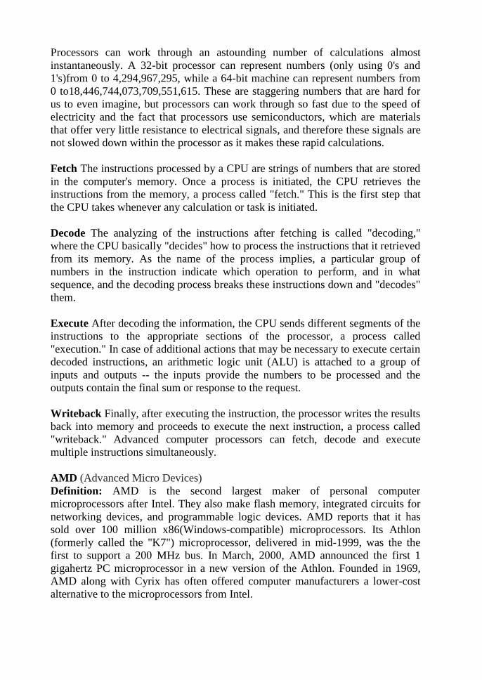
AMD (Advanced Micro Devices)
Definition: AMD is the second largest maker of personal computer
microprocessors after Intel. They also make flash memory, integrated circuits for
networking devices, and programmable logic devices. AMD reports that it has
sold over 100 million x86(Windows-compatible) microprocessors. Its Athlon
(formerly called the "K7") microprocessor, delivered in mid-1999, was the the
first to support a 200 MHz bus. In March, 2000, AMD announced the first 1
gigahertz PC microprocessor in a new version of the Athlon. Founded in 1969,
AMD along with Cyrix has often offered computer manufacturers a lower-cost
alternative to the microprocessors from Intel.
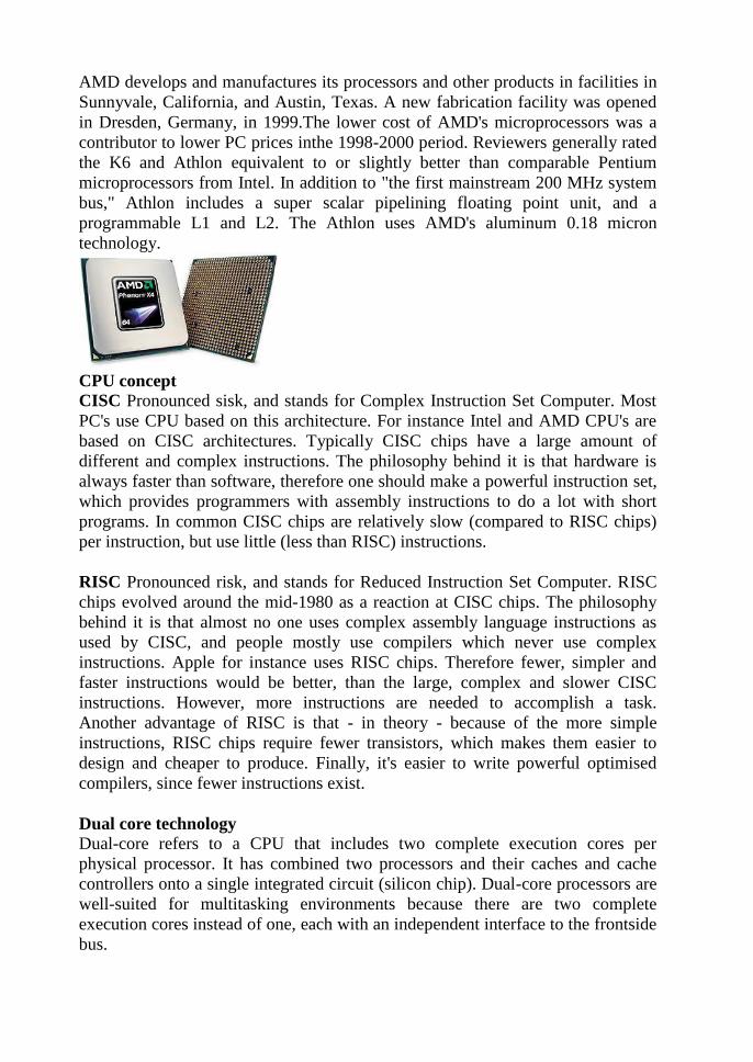
AMD develops and manufactures its processors and other products in facilities in
Sunnyvale, California, and Austin, Texas. A new fabrication facility was opened
in Dresden, Germany, in 1999.The lower cost of AMD's microprocessors was a
contributor to lower PC prices inthe 1998-2000 period. Reviewers generally rated
the K6 and Athlon equivalent to or slightly better than comparable Pentium
microprocessors from Intel. In addition to "the first mainstream 200 MHz system
bus," Athlon includes a super scalar pipelining floating point unit, and a
programmable L1 and L2. The Athlon uses AMD's aluminum 0.18 micron
technology.
CPU concept
CISC Pronounced sisk, and stands for Complex Instruction Set Computer. Most
PC's use CPU based on this architecture. For instance Intel and AMD CPU's are
based on CISC architectures. Typically CISC chips have a large amount of
different and complex instructions. The philosophy behind it is that hardware is
always faster than software, therefore one should make a powerful instruction set,
which provides programmers with assembly instructions to do a lot with short
programs. In common CISC chips are relatively slow (compared to RISC chips)
per instruction, but use little (less than RISC) instructions.
RISC Pronounced risk, and stands for Reduced Instruction Set Computer. RISC
chips evolved around the mid-1980 as a reaction at CISC chips. The philosophy
behind it is that almost no one uses complex assembly language instructions as
used by CISC, and people mostly use compilers which never use complex
instructions. Apple for instance uses RISC chips. Therefore fewer, simpler and
faster instructions would be better, than the large, complex and slower CISC
instructions. However, more instructions are needed to accomplish a task.
Another advantage of RISC is that - in theory - because of the more simple
instructions, RISC chips require fewer transistors, which makes them easier to
design and cheaper to produce. Finally, it's easier to write powerful optimised
compilers, since fewer instructions exist.
Dual core technology
Dual-core refers to a CPU that includes two complete execution cores per
physical processor. It has combined two processors and their caches and cache
controllers onto a single integrated circuit (silicon chip). Dual-core processors are
well-suited for multitasking environments because there are two complete
execution cores instead of one, each with an independent interface to the frontside
bus.

Since each core has its own cache, the operating system has sufficient sources to
handle most compute intensive tasks in parallel. Multi-core is similar to dual-core
in that it is an expansion to the dual-core technology which allows for more than
two separate processors.
Dual-Core Processors Dual-core refers to a CPU that includes two complete
execution cores per physical processor. It combines two processors and their
caches and cache controllers onto a single integrated circuit (silicon chip). It is
basically two processors, in most cases, residing reside side-by-side on the same
die.
Dual-processor, Dual-core, and Multi-core: Keeping it straight Dual-
processor (DP) systems are those that contains two separate physical computer
processors in the same chassis. In dual-processor systems, the two processors can
either be located on the same motherboard or on separate boards. In a dual-core
configuration, an integrated circuit (IC) contains two complete computer
processors. Usually, the two identical processors are manufactured so they reside
side-by-side on the same die, each with its own path to the system front-side bus.
Multi-core is somewhat of an expansion to dual-core technology and allows for
more than two separate processors.
Advantage of Dual-core Technology A dual-core processor has many
advantages especially for those looking to boost their system's multitasking
computing power. Dual-core processors provide two complete execution cores
instead of one, each with an independent interface to the frontside bus. Since each
core has its own cache, the operating system has sufficient resources to handle
intensive tasks in parallel, which provides a noticeable improvement to
multitasking. Complete optimization for the dual-core processor requires both the
operating system and applications running on the computer to support a
technology called thread-level parallelism, or TLP. Thread-level parallelism is the
part of the OS or application that runs multiple threads simultaneously, where
threads refer to the part of a program that can execute independently of other
parts. Even without a multithread-enabled application, you will still see benefits
of dual-core processors if you are running an OS that supports TLP. For example,
if you have Microsoft Windows XP (which supports multithreading), you could
have your Internet browser open along with a virus scanner running in the
background, while using Windows Media Player to stream your favorite radio
station and the dual-core processor will handle the multiple threads of these
programs running simultaneously with an increase in performance and efficiency.
Today Windows XP and hundreds of applications already support multithread
technology, especially applications that are used for editing and creating music
files, videos and graphics because types of programs need to perform operations
in parallel. As dual-core technology becomes more common in homes and the
workplace, you can expect to see more applications support thread-level
parallelism.
Pentium 4 Definition: Pentium 4 (P4) is the Intel processor (codenamed
Willamette) that was released in November 2000. The P4 processor has a viable
clock speed that now exceeds 2gigahertz (GHz) - as compared to the 1 GHz of the
Pentium 3. P4 had the first totally new chip architecture since the 1995 Pentium
Pro. The major difference involved structural changes that affected the way
processing takes place within the chip, something Intel calls NetBurst
microarchitecture. Aspects of the changes include: a 20-stage pipeline, which
boosts performance by increasing processor frequency; a rapid-execution engine,
which doubles the core frequency and reduces latency by enabling each
instruction to be executed in a half (rather than a whole)clock cycle; a 400 MHz
system bus, which enables transfer rates of 3.2 giga bytes per second (GBps); an
execution trace cache, which optimizes cache memory efficiency and reduces
latency by storing decoded sequences of micro-operations; and improved floating
point and multimedia unit and advanced dynamic execution, all of which enable
faster processing for especially demanding applications, such as digital video,
voice recognition, and online gaming. P4's main competition for processor market
share is the AMD Athlon processor. Intel Pentium 4 microprocessor family
consists of the following sub-families:* Xeon and Xeon MP - high performance
versions.* Pentium 4 - desktop CPU.* Mobile Pentium 4 and Mobile Pentium 4-
M - mobile versions of the CPU.* Celeron - low-cost version.* Mobile Celeron -
mobile version of the low-cost Pentium 4 processor. All Pentium 4-branded
processors have only one CPU core. Dual-core microprocessors based on
NetBurst microarchitecture were branded as Pentium D.
Hyper threading Definition:
Hyper-Threading is a technology used by some Intel microprocessor s that allows
a single microprocessor to act like two separate processors to the operating system
and the application program s that use it. It is a feature of Intel's IA-32 processor
architecture.
With Hyper-Threading, a microprocessor's "core" processor can execute two
(rather than one) concurrent streams (or thread s) of instructions sent by the
operating system. Having two streams of execution units to work on allows more
work to be done by the processor during each clock cycle. To the operating
system, the Hyper-Threading microprocessor appears to be two separate
processors.
Because most of today's operating systems (such as Windows and Linux) are
capable of dividing their work load among multiple processors (this is called
symmetric multiprocessing or SMP), the operating system simply acts as though
the Hyper-Threading processor is a pool of two processors.
Intel notes that existing code will run correctly on a processor with Hyper-
Threading but "some relatively simple code modifications are recommended to
get the optimum benefit.
"Hyper-Threading Technology Hyper-Threading Technology is a new
technology from Intel that enables a single processor to run two separate threads
simultaneously. This bottom line is30+% increase in performance and in media
production, performance and stability are, well, everything. Hyper-Threading
Technology enables multi-threaded software applications to execute threads in
parallel. This level of threading technology has never been seen before in a
general-purpose microprocessor. Internet, e-Business, and enterprise software
applications continue to put higher demands on processors. To improve
performance in the past, threading was enabled in the software by splitting
instructions into multiple streams so that multiple processors could act upon them.
Today with Hyper-Threading Technology, processor-level threading can be
utilized which offers more efficient use of processor resources for greater
parallelism and improved performance on today's multi-threaded software. Hyper-
Threading Technology provides thread-level-parallelism (TLP) on each processor
resulting in increased utilization of processor execution resources. As a result,
resource utilization yields higher processing throughput. Hyper-Threading
Technology is a form of simultaneous multi-threading technology (SMT) where
multiple threads of software applications can be run simultaneously on one
processor. This is achieved by duplicating the architectural state on each
processor, while sharing one set of processor execution resources. Hyper-
Threading Technology also delivers faster response times for multi-tasking
workload environments. By allowing the processor to use on-die resources that
would otherwise have been idle, Hyper-Threading Technology provides a
performance boost on multi-threading and multi-tasking operations for the Intel
NetBurst® microarchitecture. This technology is largely invisible to the platform.
In fact, many applications are already multi-threaded and will automatically
benefit from this technology. However, multi-threaded applications take full
advantage of the increased performance that Hyper-Threading Technology has to
offer, allowing users will see immediate performance gains when multitasking.
Today's multi-processing aware software is also compatible with Hyper-
Threading Technology enabled platforms, but further performance gains can be
realized by specifically tuning software for Hyper-Threading Technology. This
technology complements traditional multi processing by providing additional
headroom for future software optimizations and business growth. Some media
applications do support Hyper-Threading while others do not. Most applications
that do not support Hyper-Threading will still work with it enabled in the BIOS,
others will not. Please check compatibility with your software supplier.

UNIT–II
Memory and Daughter Boards
Memory: Introduction - Main memory – Evolution - DRAM – EDO RAM -
SDRAM – DDR
RAM versions – IT RAM – Direct RDRAM – Memory Chips
(SIMM, DIMM, RIMM)- Extended – Expanded – Cache - Virtual Memory-
Causes of false memory errors.
Graphic Cards: Introduction - Definition and Layout of Components
in Graphics card – Graphics Processor – Video memory – Memory Chart –
RAMDAC – Driver Software – 3D – Video capture card installation.
Sound Cards: Introduction - Definition of Various Components –
Connectivity –Standards – A3D – EAX – MIDI – General MIDI – PCI Audio
– USB Sound – MP3 –SDMI.
Displays: Introduction – CRT – Anatomy – Resolution – refresh rate –
interlacing –Digital CRT‘s – Panel Displays – Introduction – LCD Principles
– Plasma Displays – TFT displays.
Display adapter: Introduction - VGA and SVGA cards, flickering,
Demagnetizing and precautions.
Keyboard, and Mouse and barcode scanner: Introduction – Keyboard ,
wireless Keyboard – Signals – operation - troubleshooting - Mouse types,
connectors , Serial mouse, PS/2 mouse and Optical mouse operation –
Signals – Installation – barcode scanner - operation.

Introduction:
Sound is a relatively new capability for PCs because no-one really considered it
when the PC was first designed. The original IBM-compatible PC was designed
as a business tool, not as a multimedia machine, so it's hardly surprising that
nobody through to including and dedicated sound chip in its architecture.
Computers, after all, were seen as calculating machines; the only kind of sound
necessary was the beep that served as a warning signal. For years, the Apple
Macintosh had built-in sound capabilities
By the second half of the 1990s PCs had the processing power and storage
capacity for them to be able to handle demanding multimedia applications. The
sound card too underwent a significant acceleration in development in the late
1990s, fuelled by the introduction of AGP and the establishment of PCI-based
sound cards. Greater competition between sound card manufacturers-together
with the trend towards integrated sound-hasled to ever lower prices. However,
as the horizons for what can be done on a PC get higher and higher, there are
main many who require top-quality sound. The result is that today's add-in
sound cards don't only make games and multimedia applications sound great,
but with the right software allow users to compose, edit and mix their own
music, learn to play the instrument of their choice and record, edit and play
digital audio from a variety of sources.
What is a Sound Card?
A computer sound card is an additional card that is often included in the
motherboard. This computer component is not compulsory but it is useful to
have as most programs use a sound card.
A sound card translates signals into sounds that can be played back through
speakers. Many motherboards have a sound card built-in making it unnecessary
to have a separate sound card. A pc sound card is placed into the PCI slots of a
motherboard.
A computer sound card is used by a computer for music, sounds during
applications and entertainment (TV, movies and games).A typical sound card
usually has four ports. The largest port is the Midi/Game port, which is used for
connecting a joystick or gaming controller to. The other three ports look similar
and are generally green, pink and blue.
The pink port is for a microphone which can record sound to the computer. The
green port is line out and this is where the speakers are connected to produce
sound from the computer. The blue port is line in and this is for connecting a
CD- player or cassette tape to the computer.
Remember a sound card by itself is not enough to hear sound. You will still
need to purchase some computer speakers or a head phone set. If you want to
make use of the microphone feature then you will need to buy a computer
microphone and you should then be able to records undo to your computer.

Components of Sound card
The modern PC soundcard contains several hardware systems relating to the
production and capture of audio, the two main audio subsystems being for
digital audio capture and replay and music syn the sis along with some glue
hardware.
Historically, the replay and music synthesis subsystem has produced sound
waves in one of two ways:
1. Through an internal FM synthesizer
2. By playing a digitized, or sampled, sound.
The digital audio section of a sound card consists of a matched pair of16-bit
digital-to-analogue (DAC) and analogue-to-digital (ADC) converters and a
programmable sample rate generator. The computer reads the sample data
or from the converters. The sample rate generator clocks the converters and
is controlled by the PC. While it can be any frequency above5kHz, it's
usually a fraction of 44.1kHz.
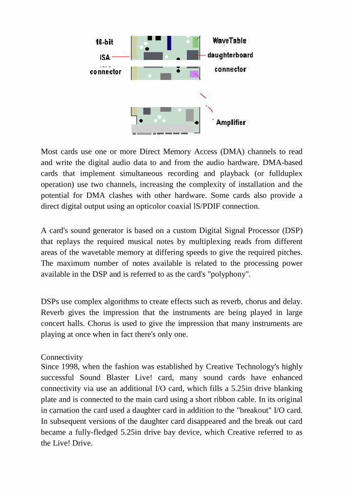
Most cards use one or more Direct Memory Access (DMA) channels to read
and write the digital audio data to and from the audio hardware. DMA-based
cards that implement simultaneous recording and playback (or fullduplex
operation) use two channels, increasing the complexity of installation and the
potential for DMA clashes with other hardware. Some cards also provide a
direct digital output using an opticolor coaxial lS/PDIF connection.
A card's sound generator is based on a custom Digital Signal Processor (DSP)
that replays the required musical notes by multiplexing reads from different
areas of the wavetable memory at differing speeds to give the required pitches.
The maximum number of notes available is related to the processing power
available in the DSP and is referred to as the card's "polyphony".
DSPs use complex algorithms to create effects such as reverb, chorus and delay.
Reverb gives the impression that the instruments are being played in large
concert halls. Chorus is used to give the impression that many instruments are
playing at once when in fact there's only one.
Connectivity
Since 1998, when the fashion was established by Creative Technology's highly
successful Sound Blaster Live! card, many sound cards have enhanced
connectivity via use an additional I/O card, which fills a 5.25in drive blanking
plate and is connected to the main card using a short ribbon cable. In its original
in carnation the card used a daughter card in addition to the "breakout" I/O card.
In subsequent versions of the daughter card disappeared and the break out card
became a fully-fledged 5.25in drive bay device, which Creative referred to as
the Live! Drive.

The Platinum 5.1 version of Creative's card-which first appeared towards the end
of 2000-sported the following jacks and connectors:
Analogue/Digital Out jack:
6-channel or compressed DolbyAC-3 SPDIF output for connection to external
digital devices or digital speaker systems; also supports center and subwoofer
analogue channels for connection to 5.1 analogue speaker systems
Line In jack:
Connects to an external device such as cassette, DAT or Mini Disc player
Microphone In jack:
Connects to an external microphone for voice input
LineOutjack:
Connects to powered speakers or an external amplifier for audio output; also
supports headphones
Rear Out jack:
Connects to powered speakers or an external amplifier for audio output
Joystick/MIDI connector:
Connects to a joystick or a MIDI device; can be adapted to connect to
both simultaneously
CD/SPDIF connector:
Connects to the SPDIF (digital audio) output, where available, on a CD-ROM
or DVD-ROM drive
AUX connector:
Connects to internal audio sources such as TV tuner, MPEG or other similar
cards
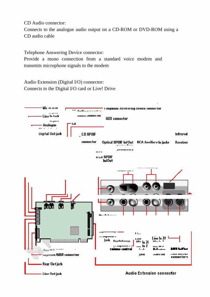
CD Audio connector:
Connects to the analogue audio output on a CD-ROM or DVD-ROM using a
CD audio cable
Telephone Answering Device connector:
Provide a mono connection from a standard voice modem and
transmits microphone signals to the modem
Audio Extension (Digital I/O) connector:
Connects to the Digital I/O card or Live! Drive
And the front panel of the Live! Drive IR device provided the following
connectivity:
RCASPDIF In/Out jacks: Connects to digital audio devices such as DAT and
Mini Disc recorders
1/4" Head phones jack: Connects to a pair of high-quality head phones;
speaker output is muted
Head phone volume: Controls the head phones output volume
1/4"LineIn2/MicIn2jack: Connects to a high-quality dynamic microphone or
audio device such as an electric guitar, DAT or Mini Disc player
Line In 2/Mic In 2 selector: Control the selection of either Line In 2 or Mic
In 2 and the microphone gain
MIDI In/Out connectors: Connects to MIDI devices via a Mini DIN-to-Standard
DIN cable
Infrared Receiver: Allows control of the PC via a remote control
RCA Auxiliary In jacks: Connects to consumer electronics equipment such as
VCR, TV and CD player
Optical SPDIF In/Out connectors: Connects to digital audio devices such as DAT
and Mini Disc recorders.
Other sound card manufacturers were quick to adopt the idea of a separate I/O
connector module. There were a number of variations on the theme. Some were
housed in an internal drive bay like the Live! Drive, others were external units,
some of which were designed to act as USB hubs.
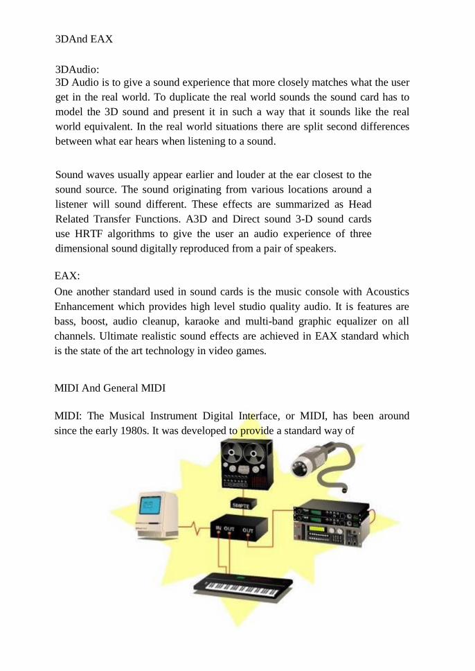
3DAnd EAX
3DAudio:
3D Audio is to give a sound experience that more closely matches what the user
get in the real world. To duplicate the real world sounds the sound card has to
model the 3D sound and present it in such a way that it sounds like the real
world equivalent. In the real world situations there are split second differences
between what ear hears when listening to a sound.
Sound waves usually appear earlier and louder at the ear closest to the
sound source. The sound originating from various locations around a
listener will sound different. These effects are summarized as Head
Related Transfer Functions. A3D and Direct sound 3-D sound cards
use HRTF algorithms to give the user an audio experience of three
dimensional sound digitally reproduced from a pair of speakers.
EAX:
One another standard used in sound cards is the music console with Acoustics
Enhancement which provides high level studio quality audio. It is features are
bass, boost, audio cleanup, karaoke and multi-band graphic equalizer on all
channels. Ultimate realistic sound effects are achieved in EAX standard which
is the state of the art technology in video games.
MIDI And General MIDI
MIDI: The Musical Instrument Digital Interface, or MIDI, has been around
since the early 1980s. It was developed to provide a standard way of
interfacing music controllers such as keyboards to sound generators like
synthesizers and drum machines. As such, it was originally designed to work via
a serial connection and can be viewed in the same light as an ASCIIRS-232
link-namely as a combination of an information transfer standard and an
electrical signal protocol.
On the electrical side, MIDI is a halfduplex 5MA current loop, which carries an
8-bit serial data stream at a bit rate of 31.25 kilobaud. The use of a current loop
means that two devices "talking" via MIDI can be electrically isolated using
opto- isolators, which is an important factor in ensuring the safe and noise-free
operation of a system encompassing both audio and computer-based hardware.
This is why a special cable is required to connect a sound card to an external
sound generator or MIDI controller, as the opto-isolators and current buffers
aren't included on most sound cards.
On the information side, MIDI is a language for describing musically important
real-time events. It communicates over 16 channels (in much the same way that
it's possible to have seven SCSI devices in a chain), allowing upto 16MIDI
instruments to be played from just one interface. Since the majority of sound
cards are multi-timbral, 16 instruments can be played simultaneously from just
one device. Adding a second MIDI interface opens up another 16 MIDI
channels. Some MIDI interfaces offer as many as 16 outputs, making it possible
to access 256 at the same time.
MIDI doesn't actually transmit sound, just very simple messages which the
receiving device responds to. Instruments are connected via standard 5-DIN
plugs. When a key is pressed on, for example, a keyboard, it sends a Note On
message down the MIDI cable instructing the receiving device to play a note.
The message consists of three elements:
• A StatusByte
• A NoteNumber
• A VelocityValue.
The Status Byte contains information about the event type (in this case a
NoteOn) and which channel it is to be sent on (1-16). The Note Number
describes the key that was pressed, say middleC, and the Velocity Value
indicates the force at which the key was struck. The receiving device will play
this note until a NoteOff message is received containing the same data.
Depending on what sound is being played, synthesisers will respond differently
to velocity.
Continuous Controllers (CCs) are used to control settings such as volume,
effects levels and pan (the positioning of sound across a stereo field). Many
MIDI devices make it possible to assign internal parameters to a CC: there are
128 to choose from. From those, the MMA (MIDI Manufacturers Association)
developed a specification for synthesisers known as General MIDI.
The first MIDI application was to allow keyboard players to "layer" the sounds
produced by several synthesisers. Today, though, it is used mainly for
sequencing. Although it has also been adopted by theatrical lighting companies
as a convenient way of controlling lights how sand projection systems.
Essentially, a sequencer is a digital tape recorder which records and plays MIDI
messages rather than audio signals. The first sequencers had very little memory,
which limited the amount of information they could store: most were only
capable of holding one or two thousand events. As sequencers became more
advanced, so did MIDI implementations. Not content with just playing
notesover MIDI, manufacturers developed ways to control individual sound
parameters and onboard digital effects using Continuous Controllers.
The majority of sequencers today are PC-based applications and have the
facility to adjust these parameters using graphical sliders. Most have an
extensive array of features for editing and fine-tuning performances, so its not
necessary to be an expert keyboard player to produce good music.
MIDI hasn't just affected the way musicians and programmers work; it has also
changed the way lighting and sound engineers work. Because almost any
electronic device can be made to respond to MIDI in some way or other, the
automation of mixing desks and lighting equipment has evolved and MIDI has
been widely adopted by theatrical lighting companies as a convenient way of
controlling light show sand projection systems. When used with a sequencer,
every action from a recording desk can be recorded, edited, and synchronized to
music or film.
General MIDI
In September of 1991 the MIDI Manufacturers Association (MMA) and the
Japan MIDI Standards Committee (JMSC) created the beginning of a newer an
MIDI technology, by adopting the "General MIDI System Level1", referred to

as GM or GM1.
The specification is designed to provide a minimum level of performance
compatibility among MIDI instruments, and has helped pave the way for MIDI
in the growing consumer and multimedia markets. The specification imposes a
number of requirements on compliant sound generating devices (keyboard,
sound module, sound card, IC, software program or other product), including
that:
• A minimum of either 24 fully dynamically allocated voices are available
simultaneously for both melodic and percussive sounds, or 16 dynamically
allocated voices are available for melodyplus 8 for percussion
• All 16 MIDI Channels are supported, each capable of playing a variable
number of voices (polyphony) or a different instrument
(sound/patch/timbre)
• A minimum of 16 simultaneous and different timbres playing various
instruments are supported as well as a minimum of 128 preset instruments
(MIDI program numbers) conforming to the GM1 Instrument Patch Map
and 47 percussion sounds which conform to the GM1 Percussion Key
Map.
When MIDI first evolved it allowed musicians to piece together musical
arrangements using whatever MIDI instruments they had. But when it came to
playing the files on other synthesisers, there was no guarantee that it would
sound the same, because different instrument manufacturers may have assigned
instruments to different program numbers: what might have been a piano on the
original synthesizer may play back as a trumpet on another. General MIDI
compliant modules no wallow music to be produced and played back regardless
of manufacturer or product.
PCI audio
PCI audio chips started to emerge during 1996 and are either integrated on the
mother board or on a cardinal PCI expansions lot. By mid-1998 a trend towards
PCI cards providing enhanced features for both gaming and music applications
had become firmly established. As greater demands are made on audio
processing, traditional cards fall short due to the physical constraints of the ISA
bus.

The problem is bandwidth. In quantitative terms, while ISA's theoretical
maximum is a mere 8MBps, the PCI bus can theoretically support data transfers
as fast as 132MBps. This limits audio to just 16channels. Whilst this is enough
for most games, for professional audio applications 32, or better still 64,
channels are preferred. Some ISA card simple proprietary technology to
increase throughput, but it is in everyone's best interests that the industry move
towards a standard.
PCI-based cards deliver greater performance, offering the performance required
by advanced features like mixing multiple audio streams and processing 3D
positional streams. Due to high overheads inherent with ISA technology, it is
estimated that upto 20% of a CPU's capacity can be blocked when playing a 16-
bit stereo sample at44.1kHz. PCI significantly reduces the performance
bottleneck, freeing up the CPU to focus on other tasks like 3D graphics, game
logic, and game physics. Overall, PCI may be as much as10 to20 times as
efficient as ISA for processing audio streams.
PCI support has been around since 1993, yet, despite the benefits it offers, it
took a further 5 years for PCI audio to emerge in a serious way. There are a
number of reasonsfor this:
• A dearth of applications that demand high-performance audio
• The technical difficulty of designing products that provide true Sound
Blaster compatibility on the PCI bus and, until relatively recently
• The high cost of early PCI audio chips.
• Now, however, PCI sound cards are often less expensive than their ISA
counterparts.
• This results partly from the speed and elegance of the PCI bus. An ISA
sound card that includes wavetable synthesis typically includes1MB to
4MB of expensive ROM to hold its wavetable synthesiser's set of sample
instrument sounds (often called a patch set or wave set).
• In contrast, many PCI cards the ROM approach in favour of loading their
patch sets into system RAM. The speed of the PCI bus enables this
approach because it gives sound cards the ability to access the samples in
system memory quickly.
• An interesting feature of the new crop of PCI audio cards was their ability
to provide real-mode DOS Sound Blaster compatibility for the huge
number of DOS games still in existence. It's significantly more
complicated to provide this compatibility with a PCI bus-based audio card
than with a PCI audio chip integrated on the motherboard.

• They also allow multiple speaker connection; soon it'll be possible to add
as many as eight speakers to a PC in a so-called 7.1 format (seven separate
positional audio channels plus one sub woofer )- a capability provided by
the "Environmental Audio" of the Sound Blaster Live! Board which came
to market in the summer of 1998.
• While PCI audio was a huge advance, initially there was one serious
problem that had be resolved to ensure that users didn't encounter
unpleasant experiences with their PCI audio subsystems.
• The problem was actually caused by certain graphics subsystems, yet it
could affect the playback quality of the PCI audi osubsystem. Some
graphics drivers continually performed retries of data transfers to the
graphics chip-where the data is transferred through, and buffered by, the
system's PCI chipset-during periods when the graphics chip was unable to
accept data.
• Apparently, this behavior enhanced graphics benchmark scores slightly,
but it could also prevent other PCI bus devices from receiving their data
through the chipset output buffers for a fairly lengthy period-long enough
to cause an audible interruption of an audio stream.
USB sound
Swiss semiconductor company Micronash as developed a technology which
could render the sound card obsolete on future multimedia PC systems. Its USB
audio controller integrates a DSP, DAC, operation amplifier, and a USB
controller into an external unit which contains everything required to balance a
loudspeaker enclosure and connect speakers directly to a personal computer
without the use of a sound card. In addition to cost reduction, the technology
offers a number of end user benefits, such as the ability to alter speaker volume
and balance on the unit itself and the ability for audio professionals to
programme the unit via an Excel spread sheet interface.
In early 2002 Creative Labs released another USB-based product, and one that
continued the theme of maximizing connectivity which had proved so popular
with their Live! Drive concept. In essence an external version of the company's
successful
Audio sound card, the Extigy's big advantage over a conventional PCI card was
its versatility, both in terms of connectivity and its ability to be used with any
type of PC-desktop, notebook or laptop.
The Extigy boasts an array of input and output jacks that will allow connection
to just about any audio device imaginable. Across the front panel there are three
inputs:
• A digital optical
• An1/8inlinein
• A microphone in with hardware-
level control. And two outputs:
• A digital optical out
• A line/headphones out with hardware-volume
control. The back panel houses three inputs:
• A USB jack
• A MIDI in
• An S/PDIF in. And five outputs:
• A MIDI out
• An S/PDIF out
• Three jacks for outputting Dolby Digital 5.1 surround sound (front, rear,
and Centre/subwoofer).
There was some disappointment that Creative chose to support the somewhat
aging USB1.1 interface in favour of a higher bandwidth alternative such as
FireWire or USB2.0. A consequence of that is that while it is ideal for recording
from external sources and highly versatile in terms of the types of PC it can be
used with, it's questionable whether it upto the job for amateur musicians
wanting to use it to record multiple tracks of audio.
Display adapter Definition:
A video adapter (alternate terms include graphics card, display adapter, video
card, video board and almost any combination of the words in these terms) is an
integrated circuit card in a computer or, in some cases, a monitor that provides
digital-to-analog conversion, video RAM, and a video controller so that data
can be sent to a computer's display. Today, almost all displays and video
adapters adhere to a common denominator defacto standard, Video Graphics
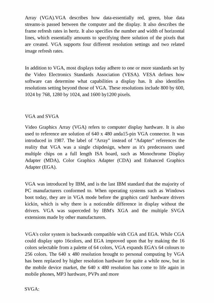
Array (VGA).VGA describes how data-essentially red, green, blue data
streams-is passed between the computer and the display. It also describes the
frame refresh rates in hertz. It also specifies the number and width of horizontal
lines, which essentially amounts to specifying there solution of the pixels that
are created. VGA supports four different resolution settings and two related
image refresh rates.
In addition to VGA, most displays today adhere to one or more standards set by
the Video Electronics Standards Association (VESA). VESA defines how
software can determine what capabilities a display has. It also identifies
resolutions setting beyond those of VGA. These resolutions include 800 by 600,
1024 by 768, 1280 by 1024, and 1600 by1200 pixels.
VGA and SVGA
Video Graphics Array (VGA) refers to computer display hardware. It is also
used to reference are solution of 640 x 480 anda15-pin VGA connector. It was
introduced in 1987. The label of "Array" instead of "Adapter" references the
reality that VGA was a single chipdesign, where as it's predecessors used
multiple chips on a full length ISA board, such as Monochrome Display
Adapter (MDA), Color Graphics Adapter (CDA) and Enhanced Graphics
Adapter (EGA).
VGA was introduced by IBM, and is the last IBM standard that the majority of
PC manufacturers conformed to. When operating systems such as Windows
boot today, they are in VGA mode before the graphics card/ hardware drivers
kickin, which is why there is a noticeable difference in display without the
drivers. VGA was superceded by IBM's XGA and the multiple SVGA
extensions made by other manufacturers.
VGA's color system is backwards compatible with CGA and EGA. While CGA
could display upto 16colors, and EGA improved upon that by making the 16
colors selectable from a palette of 64 colors, VGA expands EGA's 64 colours to
256 colors. The 640 x 480 resolution brought to personal computing by VGA
has been replaced by higher resolution hardware for quite a while now, but in
the mobile device market, the 640 x 480 resolution has come to life again in
mobile phones, MP3 hardware, PVPs and more
SVGA:

Any VGA board that offers display models beyond the standard VGA is
referred as Super VGA. To standardize the VGA cards available in the market
video electronics standards association introduced an industry standard called
VESA- SVGA in1989. When using SVGA as a direct comparison to other
display standards such as XGA (Extended Graphics Array)or VGA (Video
Graphics Array) the standard resolution referred to as SVGA is 800*600 pixels.
Although the number of colours was defined in the original specification, this
soon became irrelevant as (in contrast to the old CGA and EGA standards) the
interface between the video card and the VGA or SuperVGA monitor uses
simple analog voltages to indicate the desired colour depth. So although SVGA
is a widely used term, it has no specific definition in terms of resolution or
bitdepth. In general use, SVGA is used to describe a display capability generally
somewhere between 800x600 pixels and 1024x768 pixels at color depths
ranging from 8bits (256colors) to 16bits (65,536 colors).
Display:
A display is a computer output surface and projecting mechanism that shows
text and often graphic images to the computer user, using a cathode ray tube
(CRT), liquid crystal display (LCD), light-emitting diode, gas plasma, or other
image projection technology. The display is usually considered to include the
screen or projection surface and the device that produces the information on the
screen. In some computers, the display is packaged in a separate unit called a
monitor. In other computers, the display is integrated into a unit with the
processor and other parts of the computer. (Some sources make the distinction
that the monitor includes other signal-handling devices that feed and control the
display or projection device. However, this distinction disappears when all these
parts become integrated into a total unit, as in the case of notebook computers.)
Displays (and monitors) a real so sometimes called video display
terminals(VDTs).The terms display and monitor are often used interchangably.
Most computer displays use analog signals as input to the display image creation
mechanism. This requirement and the need to continually refresh the display
image mean that the computer also needs a display or video adapter. The video
adapter takes the digital data sent by application programs, stores it in video
random access memory(videoRAM ), and converts it to analog data for the
display scanning mechanism using an digital-to-analog converter ( DAC).
Displays can be characterized according to:
• Color capability
• Sharpness and viewability
• The size of the screen
• The projection technology
CRT
Stands for "Cathode Ray Tube." CRT is the technology used in traditional
computer monitors and televisions. The image on a CRT display is created by
firing electrons from the back of the tube to phosphors located towards the front
of the display. Once the electrons hit the phosphors, they light up and are
projected on the screen. The color you see on the screen is produced by a blend
of red, blue, and green light, often referred to as RGB.
The stream of electrons is guiding by magnetic charges, which is why you may
get interference with unshielded speakers or other magnetic devices that are
placed close to a CRT monitor. Flat screen or LCD displays don't have this
problem, since they don't require a magnetic charge. LCD monitors also don't
use a tube, which is what enables them to be much thinner than CRT monitors.
While CRT displays are still used by graphics professionals because of their
vibrant and accurate color, LCD displays now nearly match the quality of CRT
monitors. Therefore, flat screen displays are well on their way to replacing CRT

monitors in both the consumer and professional markets.
A CRT is essentially a noddly-shaped, sealed glass bottle with no air inside. It
begins with as limneck and tapers outward until it forms a large base. The base
is the monitor's "screen" and is coated on the inside with a matrix of thousands
of tiny phosphor dots. Phosphors are chemicals which emit light when excited
by a stream of electrons: different phosphors emit different coloured light. Each
dot consists of three blobs of colored phosphor: one red, one green, one blue.
These groups of three phosphors make up what is known as a single pixel.
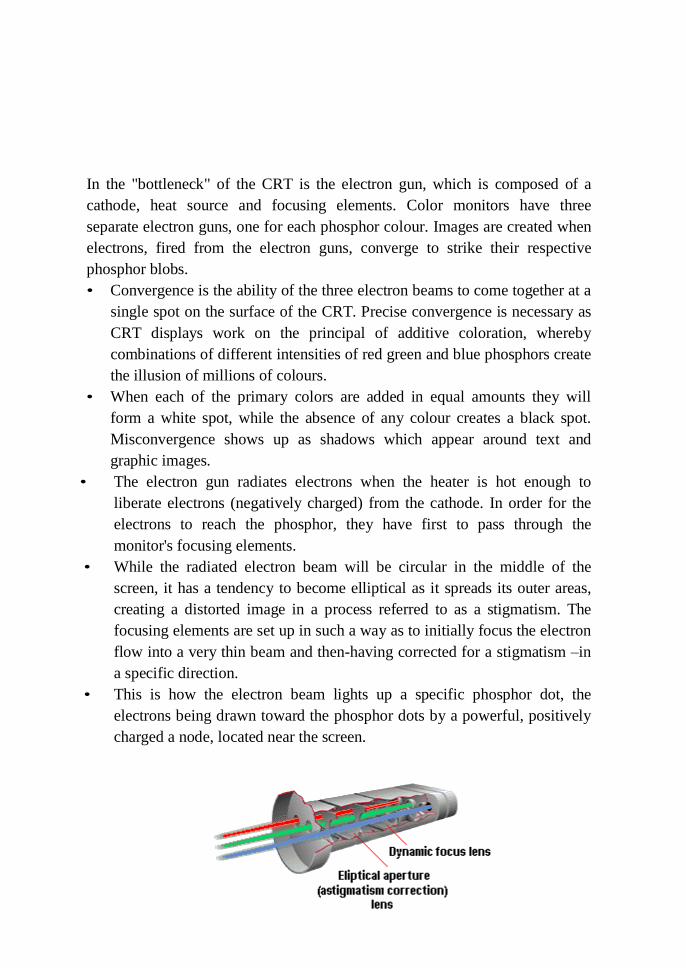
In the "bottleneck" of the CRT is the electron gun, which is composed of a
cathode, heat source and focusing elements. Color monitors have three
separate electron guns, one for each phosphor colour. Images are created when
electrons, fired from the electron guns, converge to strike their respective
phosphor blobs.
• Convergence is the ability of the three electron beams to come together at a
single spot on the surface of the CRT. Precise convergence is necessary as
CRT displays work on the principal of additive coloration, whereby
combinations of different intensities of red green and blue phosphors create
the illusion of millions of colours.
• When each of the primary colors are added in equal amounts they will
form a white spot, while the absence of any colour creates a black spot.
Misconvergence shows up as shadows which appear around text and
graphic images.
• The electron gun radiates electrons when the heater is hot enough to
liberate electrons (negatively charged) from the cathode. In order for the
electrons to reach the phosphor, they have first to pass through the
monitor's focusing elements.
• While the radiated electron beam will be circular in the middle of the
screen, it has a tendency to become elliptical as it spreads its outer areas,
creating a distorted image in a process referred to as a stigmatism. The
focusing elements are set up in such a way as to initially focus the electron
flow into a very thin beam and then-having corrected for a stigmatism –in
a specific direction.
• This is how the electron beam lights up a specific phosphor dot, the
electrons being drawn toward the phosphor dots by a powerful, positively
charged a node, located near the screen.
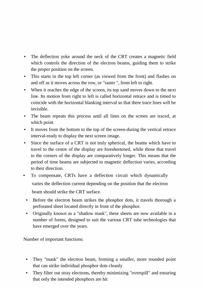
• The deflection yoke around the neck of the CRT creates a magnetic field
which controls the direction of the electron beams, guiding them to strike
the proper position on the screen.
• This starts in the top left corner (as viewed from the front) and flashes on
and off as it moves across the row, or "raster ", from left to right.
• When it reaches the edge of the screen, its top sand moves down to the next
line. Its motion from right to left is called horizontal retrace and is timed to
coincide with the horizontal blanking interval so that there trace lines will be
invisible.
• The beam repeats this process until all lines on the screen are traced, at
which point
• It moves from the bottom to the top of the screen-during the vertical retrace
interval-ready to display the next screen image.
• Since the surface of a CRT is not truly spherical, the beams which have to
travel to the centre of the display are foreshortened, while those that travel
to the corners of the display are comparatively longer. This means that the
period of time beams are subjected to magnetic deflection varies, according
to their direction.
• To compensate, CRTs have a deflection circuit which dynamically
varies the deflection current depending on the position that the electron
beam should strike the CRT surface.
• Before the electron beam strikes the phosphor dots, it travels thorough a
perforated sheet located directly in front of the phosphor.
• Originally known as a "shadow mask", these sheets are now available in a
number of forms, designed to suit the various CRT tube technologies that
have emerged over the years.
Number of important functions:
• They "mask" the electron beam, forming a smaller, more rounded point
that can strike individual phosphor dots cleanly
• They filter out stray electrons, thereby minimizing "overspill" and ensuring
that only the intended phosphors are hit
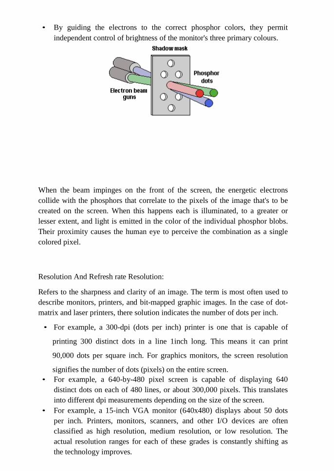
• By guiding the electrons to the correct phosphor colors, they permit
independent control of brightness of the monitor's three primary colours.
When the beam impinges on the front of the screen, the energetic electrons
collide with the phosphors that correlate to the pixels of the image that's to be
created on the screen. When this happens each is illuminated, to a greater or
lesser extent, and light is emitted in the color of the individual phosphor blobs.
Their proximity causes the human eye to perceive the combination as a single
colored pixel.
Resolution And Refresh rate Resolution:
Refers to the sharpness and clarity of an image. The term is most often used to
describe monitors, printers, and bit-mapped graphic images. In the case of dot-
matrix and laser printers, there solution indicates the number of dots per inch.
• For example, a 300-dpi (dots per inch) printer is one that is capable of
printing 300 distinct dots in a line 1inch long. This means it can print
90,000 dots per square inch. For graphics monitors, the screen resolution
signifies the number of dots (pixels) on the entire screen.
• For example, a 640-by-480 pixel screen is capable of displaying 640
distinct dots on each of 480 lines, or about 300,000 pixels. This translates
into different dpi measurements depending on the size of the screen.
• For example, a 15-inch VGA monitor (640x480) displays about 50 dots
per inch. Printers, monitors, scanners, and other I/O devices are often
classified as high resolution, medium resolution, or low resolution. The
actual resolution ranges for each of these grades is constantly shifting as
the technology improves.
Resolution of digital images:
The resolution of digital images can be described in many different ways.
Pixel resolution:
The term resolution is often used as a pixel count in digital imaging, even
though American, Japanese, and international standards specify that it should
not be so used, atleast in the digital camera field. An image of N pixels high by
M pixels wide can have any resolution less than N lines per picture height, or
NTV lines. But when the pixel counts are referred to as resolution, the
convention is to describe the pixel resolution with these of two positive integer
numbers, where the first number is the number of pixel columns (width) and the
second is the number of pixel rows (height), for example as 640 by 480.
Another popular convention is to cite resolution as the total number of pixels in
the image, typically given as number of megapixels, which can be calculated by
multiplying pixel columns by pixel rows and dividing by one million. Other
conventions include describing pixels per length unit or pixels per are a unit,
such as pixels per inch or per square inch. None of these pixel resolutions are
true resolutions, but they are widely referred to as such; they serve as upper
bounds on image resolution.
Below is an illustration of how the same image might appear at different pixel
resolutions, if the pixels were poorly rendered as sharp squares (normally, a
smooth image reconstruction from pixels would be preferred, but for illustration
of pixels, the sharp squares make the point better).
Refresh rate:
The Refresh rate is the number of times a display's image is repainted or
refreshed per second. As it denotes a frequency of a process, the refresh rate is
expressed in hertz. That is, are fresh rate of 75Hz means the image is refreshed
75 times in one second. For academic interest, it should be kept in mind that
refresh rate is different from frame rate in that refresh rate means the repeated
illumination of identical frames, while frame rate measures how often a display
image can change into another.
Calculating Maximum Refresh Rate:
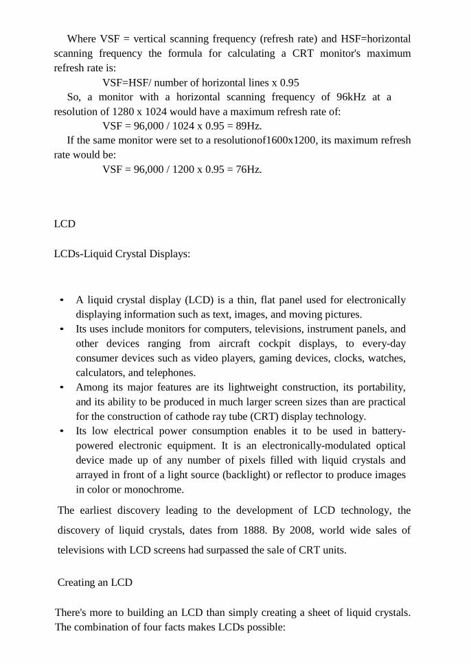
Where VSF = vertical scanning frequency (refresh rate) and HSF=horizontal
scanning frequency the formula for calculating a CRT monitor's maximum
refresh rate is:
VSF=HSF/ number of horizontal lines x 0.95
So, a monitor with a horizontal scanning frequency of 96kHz at a
resolution of 1280 x 1024 would have a maximum refresh rate of:
VSF = 96,000 / 1024 x 0.95 = 89Hz.
If the same monitor were set to a resolutionof1600x1200, its maximum refresh
rate would be:
VSF = 96,000 / 1200 x 0.95 = 76Hz.
LCD
LCDs-Liquid Crystal Displays:
• A liquid crystal display (LCD) is a thin, flat panel used for electronically
displaying information such as text, images, and moving pictures.
• Its uses include monitors for computers, televisions, instrument panels, and
other devices ranging from aircraft cockpit displays, to every-day
consumer devices such as video players, gaming devices, clocks, watches,
calculators, and telephones.
• Among its major features are its lightweight construction, its portability,
and its ability to be produced in much larger screen sizes than are practical
for the construction of cathode ray tube (CRT) display technology.
• Its low electrical power consumption enables it to be used in battery-
powered electronic equipment. It is an electronically-modulated optical
device made up of any number of pixels filled with liquid crystals and
arrayed in front of a light source (backlight) or reflector to produce images
in color or monochrome.
The earliest discovery leading to the development of LCD technology, the
discovery of liquid crystals, dates from 1888. By 2008, world wide sales of
televisions with LCD screens had surpassed the sale of CRT units.
Creating an LCD
There's more to building an LCD than simply creating a sheet of liquid crystals.
The combination of four facts makes LCDs possible:
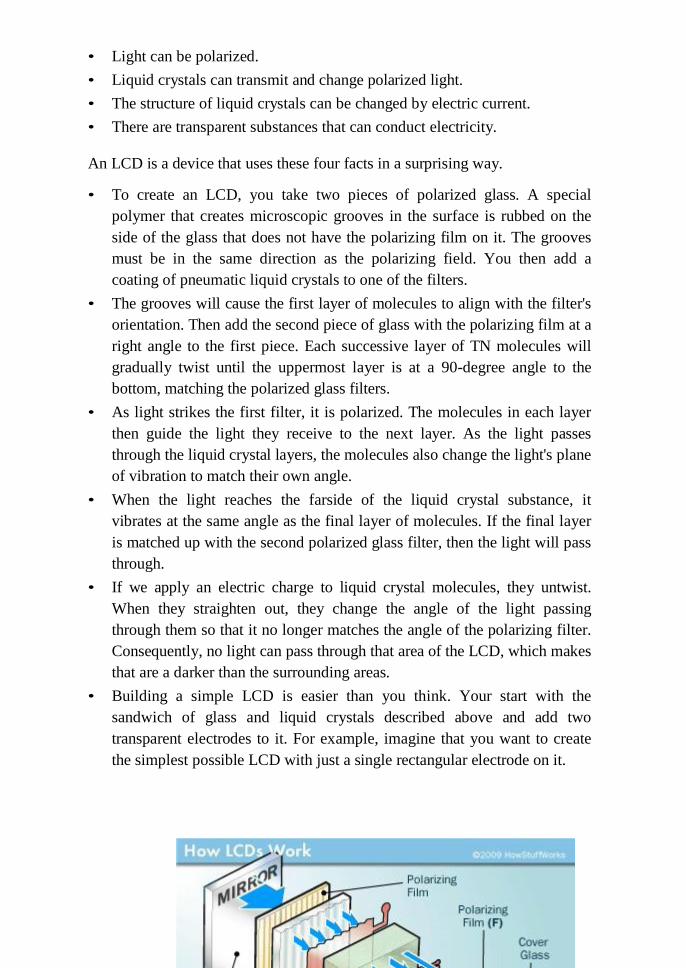
• Light can be polarized.
• Liquid crystals can transmit and change polarized light.
• The structure of liquid crystals can be changed by electric current.
• There are transparent substances that can conduct electricity.
An LCD is a device that uses these four facts in a surprising way.
• To create an LCD, you take two pieces of polarized glass. A special
polymer that creates microscopic grooves in the surface is rubbed on the
side of the glass that does not have the polarizing film on it. The grooves
must be in the same direction as the polarizing field. You then add a
coating of pneumatic liquid crystals to one of the filters.
• The grooves will cause the first layer of molecules to align with the filter's
orientation. Then add the second piece of glass with the polarizing film at a
right angle to the first piece. Each successive layer of TN molecules will
gradually twist until the uppermost layer is at a 90-degree angle to the
bottom, matching the polarized glass filters.
• As light strikes the first filter, it is polarized. The molecules in each layer
then guide the light they receive to the next layer. As the light passes
through the liquid crystal layers, the molecules also change the light's plane
of vibration to match their own angle.
• When the light reaches the farside of the liquid crystal substance, it
vibrates at the same angle as the final layer of molecules. If the final layer
is matched up with the second polarized glass filter, then the light will pass
through.
• If we apply an electric charge to liquid crystal molecules, they untwist.
When they straighten out, they change the angle of the light passing
through them so that it no longer matches the angle of the polarizing filter.
Consequently, no light can pass through that area of the LCD, which makes
that are a darker than the surrounding areas.
• Building a simple LCD is easier than you think. Your start with the
sandwich of glass and liquid crystals described above and add two
transparent electrodes to it. For example, imagine that you want to create
the simplest possible LCD with just a single rectangular electrode on it.
The layers would look like this:
• The LCD needed to do this job is very basic. It has a mirror (A) in back,
which makes it reflective. Then, we add a piece of glass (B) with a
polarizing film on the bottom side, and a common electrode plane(C) made
of indium-tinoxide on top.
• A common electrode plane covers the entire area of the LCD. Above that
is the layer of liquid crystal substance (D).
• Next comes another piece of glass (E) with an electrode in the shape of the
rectangle on the bottom and, on top, another polarizing film (F), at a right
angle to the first one.
• The electrode is hooked up to a power source like a battery.
• When there is no current, light entering through the front of the LCD will
simply hit the mirror and bounce right back out. But when the battery
supplies current to the electrodes, the liquid crystals between the common-
plane electrode and the electrode shaped like a rectangle untwist and block
the light in that region from passing through. That makes the LCDs how
the rectangle as a black area.
How LCD Works
Basic Working Principle of LCD Panel
• A LCD display consists of many pixels, this is what the resolution stands
for, the number of pixels.
• Each of these pixels is an LCD panel, and it is seen as a multi-layer
sandwich supported by a fluorescent back light.
• At the 2 far ends of the LCD panel are non-alkaline, transparent glass
subtracts with smooth surface and free of surface scratches.
• The glass substrates are attached to polarizer film that transmits or
absorbs a specific component of polarized light.
• In between the 2 glass substrates is layer of then ematicp hase liquid
crystals. There is also a colour filter containing the 3 primary colours
(red, green and blue).
• Each of the polarized glass is arranged at right angles to each other, so
when electric current was passed through the LCD panel, the liquid
crystals are aligned with the first polarized glass encountered and will
make a 90o twist when approaching the other polarized glass at the end.
• When this happens, the light from the fluorescent back light is able to
pass through and thus giving us a lighted pixel on the monitor.
• When there is no electric current, the liquid crystals will not twist and
thus the light will not pass through and a black pixel will be shown. The
reason we see the colored images are due to the colour filter, light passes
through the filtered cells creates the colors.
Plasma Displays:
Also called "gas discharge display," a flat-screen technology that uses tiny cells
lined with phosphor that are full of inert ionized gas (typically a mix of xenon
and neon).Three cells make up one pixel (one cell has red phosphor, one green,
one blue).The cells are sandwiched between x-and y-axis panels, and a cellis
selected by charging the appropriate x and y electrodes. The charge causes the
gas in the cell to emit ultra violet light, which causes the phosphor to emit color.
The amount of charge determines the intensity, and the combination of the
different intensities of red, green and blue produce all the colors required.
Plasma displays were initially monochrome, typically orange, but color displays
have become very popular and a reused for home theatre and computer
monitors as well as digital signs. The plasma technology is similar to the way
neon signs work combined with the red, green and blue phosphor technology of
a CRT. Plasma monitors consume significantly more current than LCD based
monitors.
Plasma Pixels
Each pixel is made up of three cells full of ionized gas that are lined with red,
green and blue phosphors. When charged, the gas emits ultra violet light that
causes the phosphors to emit their colors.

How does plasma display work?
• Inside a Plasma units it hundreds and thousands soft in y pixels which are
cells filled with a mixture of neon and xenon gasses.
• These cells are sandwiched between two glass panels running parallel to
each other.
• A single pixel is made up of three colored sub-pixels, one sub pixel has a
red light phosphor, one has a green light phosphor and the third has a blue
light phosphor.
• A plasma screen works by controlling each individual phosphor.
• Each phosphor is driven by its own electrode, which activates tiny pockets
of gas between the front sheet of glass and the phosphor-coated rear panel
which stimulates the gasto release ultra violet light photons, which are
invisible to the human eye.
• There leased ultra violet photons interact with phosphor material coated on
the inside wall of the cell.
• Phosphors are substances that give off light when they are exposed to other
lighteg. Ultra violet light.
• The phosphors in a pixel give off colored light when they are charged.
• The cells are situated in a grid like structure, the plasma display's computer
charges the electrodes that intersect at that cell.
• It does this thousands of times a second, charging each cell, which
effectively turns the pixel on and off to allow the creation of movement
and colour change on the screen.
• The varying intensity of the current can create millions of different
combinations of red, green and blue across the entire spectrum of color.
TFT-LCD
TFT-LCD (Thin Film Transistor – Liquid Crystal Display) is a variant of Liquid
Crystal Display (LCD) which uses Thin-Film Transistor (TFT) technology to
improve image quality. TFTL CD is one type of active matrix LCD, though it is
usually synonymous with LCD. It is used in both flat panel displays and
projectors. In computing, TFT monitors are rapidly displacing competing CRT
technology, and are commonly available in sizes from 12 to 30 inches. As of
2006, they have also made in roads on the television market.
Construction:
• Normal Liquid Crystal Displays like those found in calculators have direct
driven image elements-a voltage can be applied across one segment
without interfering with other segments of the display.
• This is impractical for a large display with a large number of picture
elements (pixels), since it would require millions of connections-top and
bottom connections for each one of the three colors(red, green and blue) of
every pixel.
• To avoid this issue, the pixels are addressed n rows and columns which
reduce the connection count from millions to thousands. If all the pixels in
one row are driven with a positive voltage and all the pixels in one column
are driven with a negative voltage, then the pixel at the intersection has the
largest applied voltage and is switched.
• The problem with this solution is that all the pixels in the same column see
a fraction of the applied voltage as do all the pixels in the same row, so
although they are not switched completely, they do tend to darken.
• The solution to the problem is to supply each pixel with its own transistor
switch which allows each pixel to be individually controlled. The low
leakage current of the transistor also means that the voltage applied to the
pixel does not leak away between refreshes to the display image.
• Each pixel is a small capacitor with a transparent ITO layer at the front, a
transparent layer at the back, and a layer of insulating liquid crystal
between.
• The circuit layout of a TFT – LCD is very similar to the one used in a
DRAM memory. However, rather than building the transistors out of
silicon which has been formed into a crystal line wafer, they are fabricated
from a thin film of silicon deposited on a glass panel.
• Transistors take up only a small fraction of the area of each pixel, and the
silicon film is etched away in the remaining areas, allowing light to pass
through.
• The silicon layer for TFT- LCDs is typically deposited using the PECVD
process from asilane gas precursor to produce an amorphous silicon film.
• Polycrystalline silicon is also used in some displays where higher
performance is needed from the TFTs, typically in very high resolution
displays or ones where performing some data processing on the display
itself is desirable.
• Both amorphous and poly crystalline silicon TFTs have very poor
performance compared with transistors fabricated from single-crystal
silicon.
Types
Twisted nematic (TN):
• The inexpensive twisted nematic display is the most common consumer
display type. The pixel response time on modern TN panels is sufficiently
fast to avoid the shadow-trail and ghosting artifacts of earlier production.
• The fast response time has been emphasized in advertising TN displays,
although in most cases this number does not reflect performance across the
entire range of possible color transitions. More recent use of RTC
(Response Time Compensation—Overdrive) technologies has allowed
manufacturers to significantly reduce grey-to-grey (G2G) transitions,
without significantly improving the ISO response time.
• Response times are now quoted in G2G figures, with 4ms and 2ms now
being common place for TN-based models. The good response time and
low cost has led to the dominance of TN in the consumer market.
• TN displays suffer from limited viewing angles, especially in the vertical
direction. Colors will shift when viewed off-perpendicular. In the vertical
direction, colors will shift so much that they will invert past a certain
angle.
• Also, TN panels represent colors using only 6bits per color, instead of 8,
and thus are notable to display the 16.7million color shades (24-bit
truecolor) that are available from graphics cards. Instead, these panels
display interpolated 24-bit color using a dithering method that combines
adjacent pixels to simulate the desired shade. They can also use Frame
Rate Control (FRC), which cycles pixels on and off to simulate a given
shade.
• These color simulation methods are noticeable to many people and
bothersome to some. FRC tends to be most noticeable in darker tones,
while dithering appears to make the individual pixels of the LCD visible.
Overall, color reproduction and linearity on TN panels is poor.
• Shortcomings in display color gamut (often referred to as a percentage of
the NTSC1953color gamut) are also due to back lighting technology.
• It is not uncommon for displays with CCFL (Cold Cathode Fluorescent
Lamps) – based lighting to range from 10 % to 26% of the NTSC color
gamut, whereas other kind of displays, utilizing RGB LED backlights, may
extend past 100%of the NTSC color gamut—a difference quite perceivable
by the human eye.
• The transmittance of a pixel of an LCD panel typically does not change
linearly with the applied voltage, and the RGB standard for computer
monitors requires a specific nonlinear dependence of the amount of
emitted light as a function of the RGB value.
IPS:
• IPS (In-Plane Switching) was developed by Hitachiin 1996 to improve
on the poor viewing angles and color reproduction of TN panels. Most
also support true 8-bitcolor.These improvements came at a loss of
response time, which was initially on the order of 50ms .IPS panels
were also extremely expensive.
• IPS has since been superseded by S-IPS (Super-IPS,Hitachiin1998), which
has all the benefits of IPS technology with the addition of improved pixel
refresh timing. Though color reproduction approaches that of CRTs, the
contrast ratio remains relatively weak. S-IPS technology is widely used in
panel sizes of 20" and above. L G and Philips remain one of the main
manufacturers of S-IPS based panels.
• AS-IPS-Advanced Super IPS, also developed by Hitachiin 2002, improves
substantially on the contrast ratio of traditional S-IPS panels to th epoint
where they are second only to some S-PVAs. AS-IPS is also a term used
for NEC displays (e.g.NECLCD20WGX2) based on S-IPS technology, in
this case, developed by LG.Philips.
• A-TW-IPS-Advanced True White IPS, developed by LG.Philips LCD for
NEC, is accustom S-IPS panel with a TW (TrueWhite) color filter to make
white look more natural and to increase color gamut. This isused in
professional/photography LCDs.
MVA:
• MVA (Multi-domain Vertical Alignment) was originally developed in
1998 by Fujitsu as a compromise between TN and IPS. It achieved fast
pixel response (at the time), wide viewing angles, and high contrast at the
cost of brightness and color reproduction.
• Modern MVA panels can offer wide viewing angles (second only to S-IPS
technology), good black depth, good color reproduction and depth, and fast
response times thanks to the use of RTC technologies.
• There are several "next generation" technologies based on MVA, including
AU Optronics'P-MVA and A-MVA, as well as ChiMei Optoelectronics' S-
MVA.
• Analysts predicted that MVA would corner the mainstream market, but
instead, TN has risen to dominance.
• A contributing factor was the higher cost of MVA, along with its slower
pixel response (which rises dramatically with small changes in brightness).
Cheaper MVA panels can also use dithering/FRC.
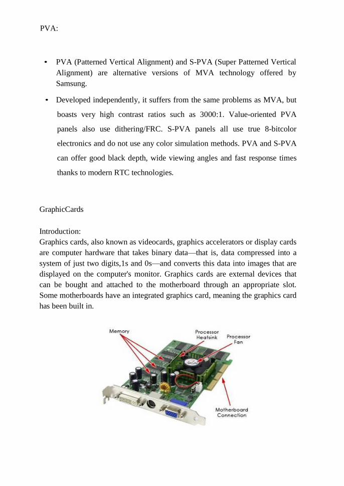
PVA:
• PVA (Patterned Vertical Alignment) and S-PVA (Super Patterned Vertical
Alignment) are alternative versions of MVA technology offered by
Samsung.
• Developed independently, it suffers from the same problems as MVA, but
boasts very high contrast ratios such as 3000:1. Value-oriented PVA
panels also use dithering/FRC. S-PVA panels all use true 8-bitcolor
electronics and do not use any color simulation methods. PVA and S-PVA
can offer good black depth, wide viewing angles and fast response times
thanks to modern RTC technologies.
GraphicCards
Introduction:
Graphics cards, also known as videocards, graphics accelerators or display cards
are computer hardware that takes binary data—that is, data compressed into a
system of just two digits,1s and 0s—and converts this data into images that are
displayed on the computer's monitor. Graphics cards are external devices that
can be bought and attached to the motherboard through an appropriate slot.
Some motherboards have an integrated graphics card, meaning the graphics card
has been built in.
Like a motherboard, a graphics card is a printed circuit board that houses a
processor and RAM. It also has an input/output system (BIOS) chip, which
stores the card's settings and performs diagnostics on the memory, input and
output at startup. A graphics card's processor, called a graphics processing unit
(GPU), is similar to a computer's CPU. A GPU, however, is designed
specifically for performing the complex mathematical and geometric
calculations that are necessary for graphics rendering. Some of the fastest GPUs
have more transistors than the average CPU. A GPU produces a lot of heat, so it
is usually located under a heats ink or a fan.
Driver software & RAMDAC Driver software:
A modern graphics card's driver software is vitally important when it comes to
performance and features. For most applications, the drivers translate what the
application wants to display on the screen into instructions that the graphics
processor can use. The way the drivers translate these instructions is of
paramount importance. Modern graphics processors do more than change single
pixels at a time; they have sophisticated line and shape drawing capabilities,
they can move large blocks of information around and a lot more besides. It is
the driver's job to decide on the most efficient way to use these graphics process
or features, depending on what the application requires to be displayed.
In most cases, a separate driver is used for each resolution or color depth. This
means that, even taking into account the different overheads associated with
different resolutions and colors, a graphics card can have markedly different
performance at different resolutions, depending on how well a particular driver
has been written and optimized.
RAMDAC:
The screen image information stored in the video memory (RAM) is digital,
because computers operate on digital numbers. Every value is stored assets of
ones and zeros; in the case of video data, the patterns of ones and zeros control
the color and intensity of every pixel on the screen. The monitor is analog. In
order to display the image on the screen, the information in video memory must
be converted to analog signals and sent to the monitor. The device that does this
is called the RAMDAC, which stands for Random Access Memory Digital
Analog Converter.
Many times per second, the RAMDAC reads the contents of video memory,
converts the information and sends it over the video cable to the monitor. The
type and speed of the RAMDAC has a direct impact on the quality of the screen
image, how often the screen can be refreshed per seconds, and the maximum
resolution and number of colors that we can display.
The A/D (analog to digital, the RAMDAC of the video card) and D/A (digital to
analog) conversions only reduce image quality on a flat panel monitor-nothing
else! Hence, the digital interface by-pass the RAMDAC of the graphics
controller:
The early VGA systems were slow. The CPU had a heavy work load processing
the graphics data, and the quantity of data transferred across the bus to the
graphics card placed excessive burdens on the system. The problems were
exacerbated by the fact that ordinary DRAM graphics memory couldn't be
written to and read from simultaneously, meaning that the RAMDAC would
have to wait to read the data while the CPU wrote, and vice versa.
Many times per second, the RAMDAC reads the contents of the video memory,
converts it into an analogue RGB signal and sends it over the video cable to the
monitor. It does this by using a look-up table to convert the digital signal to a
voltage level for each colour. There is one Digital-to-Analogue Converter
(DAC) for each of the three primary colours the CRT uses to create a complete
spectrum of colours. The intended result is the right mix needed to create the
colour of a single pixel. The rate at which the RAMDAC can convert the
information, and the design of the graphics processor itself, dictates the range of
refresh rates that the graphics card can support. The RAMDAC also dictates the
number of colours available in a given resolution, depending on its internal
architecture.
The problem was solved by the introduction of dedicated graphics processing
chips on modern graphics cards. Instead of sending a raw screen image across to
the frame buffer, the CPU sends a smaller set of drawing instructions, which are
interpreted by the graphics card's proprietary driver and executed by the card's
on- board processor.
Operations including bitmap transfers and painting, window resizing and
repositioning, line drawing, font scaling and polygon drawing can be handled by
the card's graphics processor, which is designed to handle these tasks in
hardware at far greater speeds than the software running on the system's CPU.
The graphics processor then writes the frame data to the frame buffer. As there's
less data to transfer, there's less congestion on the system bus, and the PC's CPU
workload is greatly reduced.
Video Memory
The memory that holds the video image is also referred to as the frame buffer
and is usually implemented on the graphics card itself. Early systems
implemented video memory in standard DRAM. However, this requires
continual refreshing of the data to prevent it from being lost and cannot be
modified during this refresh process. The consequence, particularly at the very
fast clock speeds demanded by modern graphics cards, is that performance is
badly degraded.
An advantage of implementing video memory on the graphics board itself is that
it can be customized for its specific task and, indeed, this has resulted in a
proliferation of new memory technologies:
Video RAM (VRAM):
A special type of dual-ported DRAM, which can be written to and read from at
the same time. It also requires far less frequent refreshing than ordinary DRAM
and consequently performs much better
Windows RAM (WRAM):
Asused by the hugely successful Matrox Millennium card, is also dual-ported
and can run slightly faster than conventional VRAM
EDODRAM:
Which provides a higher band width than DRAM, can be clocked higher than
normal DRAM and manages the read/write cycles more efficiently
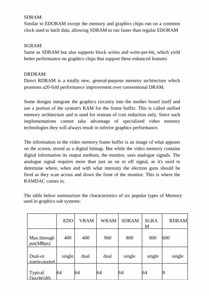
SDRAM:
Similar to EDORAM except the memory and graphics chips run on a common
clock used to latch data, allowing SDRAM to run faster than regular EDORAM
SGRAM:
Same as SDRAM but also supports block writes and write-per-bit, which yield
better performance on graphics chips that support these enhanced features
DRDRAM:
Direct RDRAM is a totally new, general-purpose memory architecture which
promises a20-fold performance improvement over conventional DRAM.
Some designs integrate the graphics circuitry into the mother board itself and
use a portion of the system's RAM for the frame buffer. This is called unified
memory architecture and is used for reasons of cost reduction only. Since such
implementations cannot take advantage of specialized video memory
technologies they will always result in inferior graphics performance.
The information in the video memory frame buffer is an image of what appears
on the screen, stored as a digital bitmap. But while the video memory contains
digital information its output medium, the monitor, uses analogue signals. The
analogue signal requires more than just an on or off signal, as it's used to
determine where, when and with what intensity the electron guns should be
fired as they scan across and down the front of the monitor. This is where the
RAMDAC comes in.
The table below summarizes the characteristics of six popular types of Memory
used in graphics sub systems:
EDO
VRAM
WRAM
SDRAM
SGRA
M
RDRAM
Max.through
put(MBps)
400
400
960
800
800
600
Dual-or
single-ported
single
dual
dual
single
single
single
Typical
DataWidth
64
64
64
64
64
8
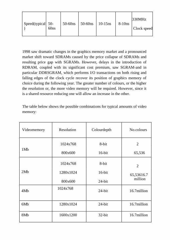
1998 saw dramatic changes in the graphics memory market and a pronounced
market shift toward SDRAMs caused by the price collapse of SDRAMs and
resulting price gap with SGRAMs. However, delays in the introduction of
RDRAM, coupled with its significant cost premium, saw SGRAM-and in
particular DDRSGRAM, which performs I/O transactions on both rising and
falling edges of the clock cycle recover its position of graphics memory of
choice during the following year. The greater number of colours, or the higher
the resolution or, the more video memory will be required. However, since it
is a shared resource reducing one will allow an increase in the other.
The table below shows the possible combinations for typical amounts of video
memory:
Videomemory
Resolution
Colourdepth
No.colours
1Mb
1024x768
8-bit
2
5
6
800x600 16-bit 65,536
2Mb
1024x768
8-bit
2
5
6 1280x1024 16-bit
65,53616.7
800x600
24-bit
million
4Mb
1024x768 24-bit
16.7million
6Mb 1280x1024 24-bit 16.7million
8Mb 1600x1200 32-bit 16.7million
Speed(typical
)
50-
60ns
50-60ns
50-60ns
10-15ns
8-10ns
330MHz
Clock speed
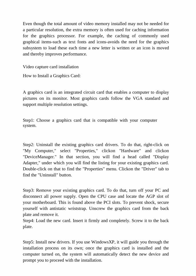
Even though the total amount of video memory installed may not be needed for
a particular resolution, the extra memory is often used for caching information
for the graphics processor. For example, the caching of commonly used
graphical items-such as text fonts and icons-avoids the need for the graphics
subsystem to load these each time a new letter is written or an icon is moved
and thereby improves performance.
Video capture card installation
How to Install a Graphics Card:
A graphics card is an integrated circuit card that enables a computer to display
pictures on its monitor. Most graphics cards follow the VGA standard and
support multiple resolution settings.
Step1: Choose a graphics card that is compatible with your computer
system.
Step2: Uninstall the existing graphics card drivers. To do that, right-click on
"My Computer," select "Properties," clickon "Hardware" and clickon
"DeviceManager." In that section, you will find a head called "Display
Adapter," under which you will find the listing for your existing graphics card.
Double-click on that to find the "Properties" menu. Clickon the "Driver" tab to
find the "Uninstall" button.
Step3: Remove your existing graphics card. To do that, turn off your PC and
disconnect all power supply. Open the CPU case and locate the AGP slot of
your motherboard. This is found above the PCI slots. To prevent shock, secure
yourself with antistatic wriststrap. Unscrew the graphics card from the back
plate and remove it.
Step4: Load the new card. Insert it firmly and completely. Screw it to the back
plate.
Step5: Install new drivers. If you use WindowsXP, it will guide you through the
installation process on its own; once the graphics card is installed and the
computer turned on, the system will automatically detect the new device and
prompt you to proceed with the installation.
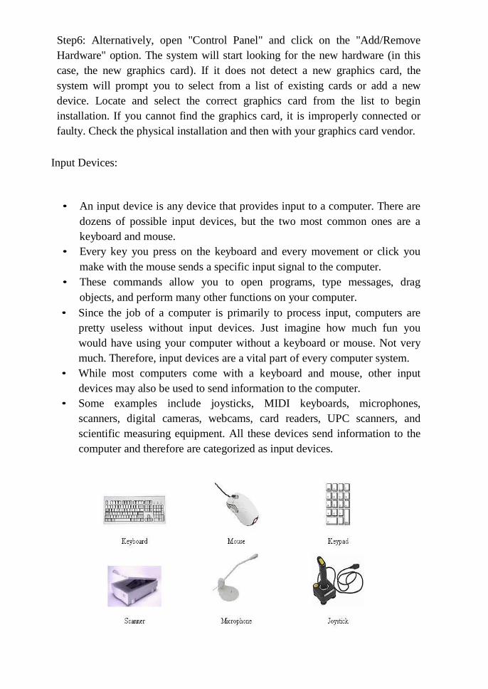
Step6: Alternatively, open "Control Panel" and click on the "Add/Remove
Hardware" option. The system will start looking for the new hardware (in this
case, the new graphics card). If it does not detect a new graphics card, the
system will prompt you to select from a list of existing cards or add a new
device. Locate and select the correct graphics card from the list to begin
installation. If you cannot find the graphics card, it is improperly connected or
faulty. Check the physical installation and then with your graphics card vendor.
Input Devices:
• An input device is any device that provides input to a computer. There are
dozens of possible input devices, but the two most common ones are a
keyboard and mouse.
• Every key you press on the keyboard and every movement or click you
make with the mouse sends a specific input signal to the computer.
• These commands allow you to open programs, type messages, drag
objects, and perform many other functions on your computer.
• Since the job of a computer is primarily to process input, computers are
pretty useless without input devices. Just imagine how much fun you
would have using your computer without a keyboard or mouse. Not very
much. Therefore, input devices are a vital part of every computer system.
• While most computers come with a keyboard and mouse, other input
devices may also be used to send information to the computer.
• Some examples include joysticks, MIDI keyboards, microphones,
scanners, digital cameras, webcams, card readers, UPC scanners, and
scientific measuring equipment. All these devices send information to the
computer and therefore are categorized as input devices.
Bar code scanner Definition:
A barcode (often seen as a single word, barcode) is the small image of lines
(bars) and spaces that is a fixed to retail store items, identification cards, and
postal mail to identify a particular product number, person, or location. The
code uses a sequence of vertical bars and space store present numbers and other
symbols. A barcode symbol typically consists of five parts: a quiet zone, a start
character, data characters (including an optional check character), as top
character, and another quiet zone.
A barcode reader is used to read the code. The reader uses a laser beam that is
sensitive to the reflections from the line and space thickness and variation. The
reader translates the reflected light into digital data that is transferred to a
computer for immediate action or storage. Barcodes and readers are most often
Seen in super markets and retail stores, but a large number of different uses
have been found for them. They are also used to take inventory in retail stores;
to check out books from a library; to track manufacturing and shipping
movement; to sign in on a job; to identify hospital patients; and to tabulate the
results of direct mail marketing returns. Very small barcodes have been used to
tag honey bees used in research. Readers may be attached to a computer (as they
often are in retail store settings) or separate and portable, in which case they
store the data they read until it can be fed into a computer.
There is no one standard barcode; instead, there are several different barcode
standards called symbologies that serve different uses, industries, or geographic
needs. Since 1973, the Uniform Product Code (UPC), regulated by the Uniform
Code Council, an industry organization, has provided a standard barcode used
by most retail stores. The European Article Numbering system (EAN),
developed by Joe Woodland, the inventor of the first barcode system, allows for
an extra pair of digits and is becoming widely used. POSTNET is the standard
barcode used in the United States for ZIP codes in bulk mailing.

Bar Code Structure
A standard 1D bar code is a series of varying width vertical lines (called bars)
and spaces. Bars and spaces together are named "elements". There are different
combinations of the bars and spaces which represent different characters.
When a barcode scanner is passed over the barcode, the light source from the
scanner is absorbed by the dark bars and not reflected, but it is reflected by the
light spaces. A photocell detect or in the scanner receives the reflected light and
converts the light into an electrical signal.

As the wand is passed over the barcode, the scanner creates a low electrical
signal for the spaces (reflected light) and a high electrical signal for the bars
(nothing is reflected); the duration of the electrical signal determines wide vs.
narrow elements. This signal can be "decoded" by the barcode reader's decoder
into the characters that the barcode represents. The decoded data is then passed
to the computer in a traditional data format.
Hand Held Types
These light weight barcode scanners are operated manually by firing a
connected with computer generally trigger. It can be used in any area, where
required scanning distance retail, libraries, service sector, courier industry,
hospitals. These are most economical scanning option. This category of scanners
are backed by CCD/Laser /Imaging technology.
Table Top:
This category of scanners are little bigger & heavy, compared to hand held ones
connected with computers. These are also known as stationary scanner as they
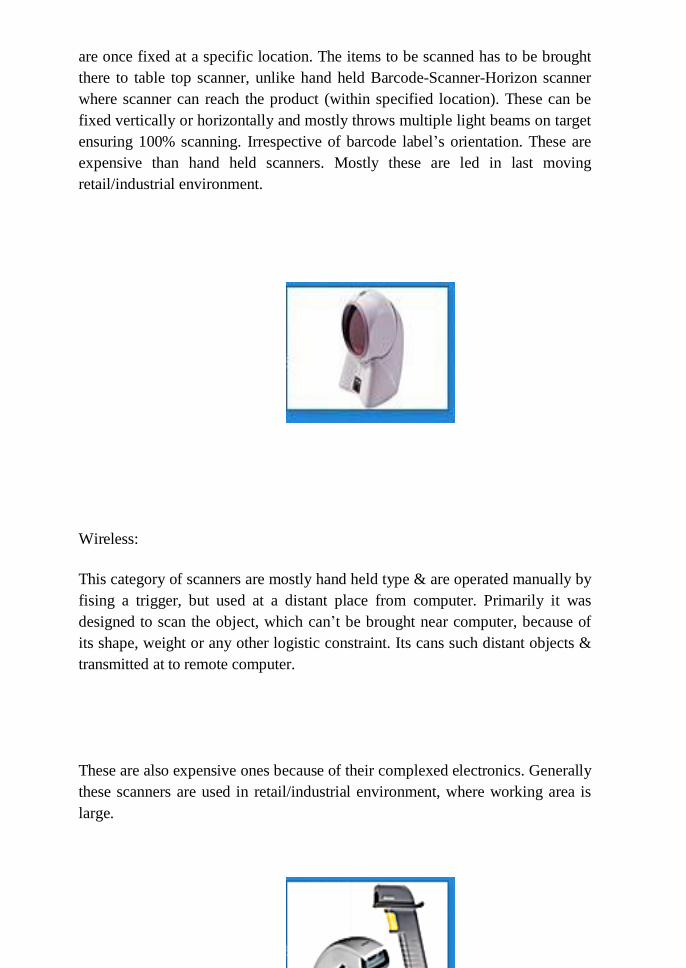
are once fixed at a specific location. The items to be scanned has to be brought
there to table top scanner, unlike hand held Barcode-Scanner-Horizon scanner
where scanner can reach the product (within specified location). These can be
fixed vertically or horizontally and mostly throws multiple light beams on target
ensuring 100% scanning. Irrespective of barcode label‘s orientation. These are
expensive than hand held scanners. Mostly these are led in last moving
retail/industrial environment.
Wireless:
This category of scanners are mostly hand held type & are operated manually by
fising a trigger, but used at a distant place from computer. Primarily it was
designed to scan the object, which can‘t be brought near computer, because of
its shape, weight or any other logistic constraint. Its cans such distant objects &
transmitted at to remote computer.
These are also expensive ones because of their complexed electronics. Generally
these scanners are used in retail/industrial environment, where working area is
large.

Memory Scanners:
This category of scanners are very light weight & hand held. These are use data
distant location, where you can‘t carry, computer and compare to wireless
scanner, very economical. It can be used in any environment
(retail/export/library/ hospital/courier/service/industry), where little amount of
data needs to be scanned at a remote location, stored & later transferred to
computer for further processing.
Key board
• In computing, a keyboard is an input device, partially modeled after the
typewriter keyboard, which uses an arrangement of buttons or keys, to act
as mechanical levers or electronic switches.
• A keyboard typically has characters engraved or printed on the keys and
each press of a key typically corresponds to a single written symbol.
However, to produce some symbols requires pressing and holding several
keys simultaneously or in sequence.
• While most keyboard keys produce letters, numbers or signs (characters),
other keys or simultaneous key presses can produce actions or computer
commands.
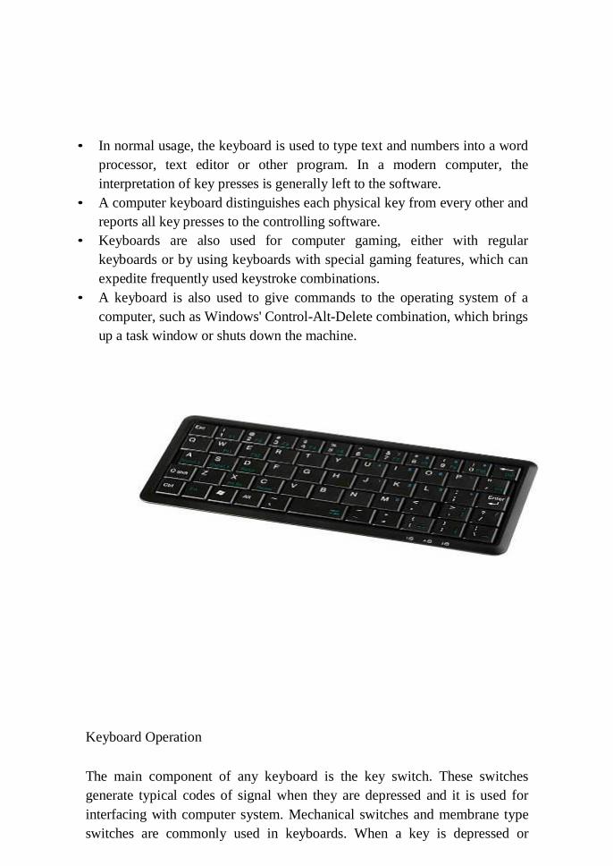
• In normal usage, the keyboard is used to type text and numbers into a word
processor, text editor or other program. In a modern computer, the
interpretation of key presses is generally left to the software.
• A computer keyboard distinguishes each physical key from every other and
reports all key presses to the controlling software.
• Keyboards are also used for computer gaming, either with regular
keyboards or by using keyboards with special gaming features, which can
expedite frequently used keystroke combinations.
• A keyboard is also used to give commands to the operating system of a
computer, such as Windows' Control-Alt-Delete combination, which brings
up a task window or shuts down the machine.
Keyboard Operation
The main component of any keyboard is the key switch. These switches
generate typical codes of signal when they are depressed and it is used for
interfacing with computer system. Mechanical switches and membrane type
switches are commonly used in keyboards. When a key is depressed or
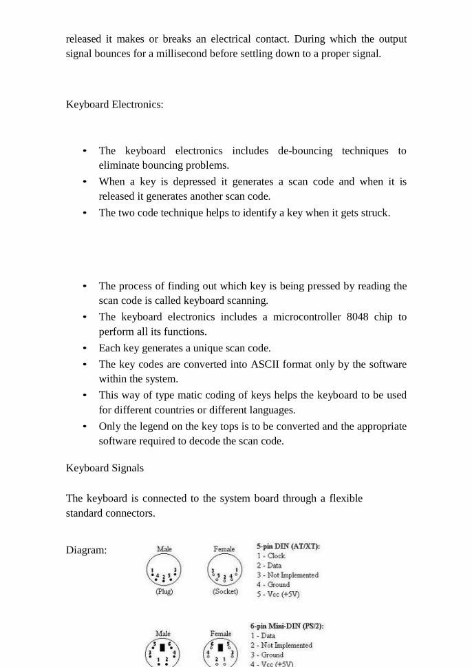
released it makes or breaks an electrical contact. During which the output
signal bounces for a millisecond before settling down to a proper signal.
Keyboard Electronics:
• The keyboard electronics includes de-bouncing techniques to
eliminate bouncing problems.
• When a key is depressed it generates a scan code and when it is
released it generates another scan code.
• The two code technique helps to identify a key when it gets struck.
• The process of finding out which key is being pressed by reading the
scan code is called keyboard scanning.
• The keyboard electronics includes a microcontroller 8048 chip to
perform all its functions.
• Each key generates a unique scan code.
• The key codes are converted into ASCII format only by the software
within the system.
• This way of type matic coding of keys helps the keyboard to be used
for different countries or different languages.
• Only the legend on the key tops is to be converted and the appropriate
software required to decode the scan code.
Keyboard Signals
The keyboard is connected to the system board through a flexible
standard connectors.
Diagram:
Keyboard Trouble shooting
Keyboard Is Dirty:
Keyboards should be cleaned with "spray-n-wipe" cleaner and a cloth or
tissue on a monthly basis. Ensure that computer is not powered up while
cleaning the keyboard. Compressed air can also be used to clean between the
keyboard keys. Another tip: clean the keys with a cotton swab dipped in
alcohol.
"Keyboard Not Found" Message:
Your keyboard is not plugged into the computer securely. Unplug it and plug
it back in and the problem should go away. If this doesn't work, follow
procedure: ―Computer isn't taking inputs from keyboard‖ (below).
Key Is Stuck:
1. If a key does not work or is stuck in the down position, you may try to
remove it with a CPU" chip puller" tool. These simple "L" shaped tools are
great at pulling out keys.
2. Once you've pulled out the stuck key, you can try to stretch the
spring to "re animate" its action.
Computer Isn't Taking Inputs From Keyboard:
1. Is keyboard connected to computer? Ensure that the keyboard is plugged
into the keyboard jack and not into the mouse jack. If the keyboard was
unplugged, plug it back in and reboot the computer.
2. If the keyboard still doesn't work on boot-up, power down the computer
and try to borrow a friend‘s known-good keyboard for trouble shooting.
Plug the new keyboard up and boot up the computer. If the new keyboard
works, the old keyboard is bad and needs to be replaced.
3. If the known-good keyboard doesn't work, check your BIOS to make
sure it sees the keyboard. It should say, "installed" If the BIOS recognizes
the keyboard, then you probably have a bad keyboard port.
Plugged Keyboard Into Mouse Port:
1. Many mice and keyboards today use a PS/2 connector. If you plugged your
keyboard into the mouse port (or vice versa), follow steps2 and 3.
2. Shutdown the computer and plug the keyboard into the keyboard port. The
keyboard port is usually marked with a "keyboard" symbol. Plug the mouse
into the mouse port (usually marked with a mouse symbol).
3. Reboot the computer; the keyboard should work now. If keyboard doesn't
work, check your BIOS to make sure the BIOS recognizes the keyboard.
You should see the words, "installed" or "enabled" under the keyboard.
4. If the BIOS recognizes the keyboard but it still doesn't work, you may
have a bad keyboard port.
Mouse:
A pointing device that is pushed around a desk area with the palm of your
hand. Traditionally mice have used rollerball sto detect motion, but newer
models feature no moving parts and use integrated circuits that detect
movement over the desktop and translate that into motion.
The most commonly used computer {pointing device}, first introduced by
{Douglas Engel bart} in 1968.
The mouse is a device used to manipulate an on-screen pointer that's
normally shaped like a narrow. With the mouse in hand, the
computer user can select, move, and change items on the screen.
As the mouse moves, a ball set in a depression on the underside of the
mouse rolls accordingly. The ball is also in contact with two small
shafts set at right angles to each other inside the mouse.
The rotating ball turns the shafts, and sensors inside the mouse
measure the shafts' rotation.
The distance and direction information from the sensors is then
transmitted to the computer, usually through a connecting wire-the
mouse's "tail".
The computer then moves the mouse pointer on the screen to follow
the movements of the mouse.
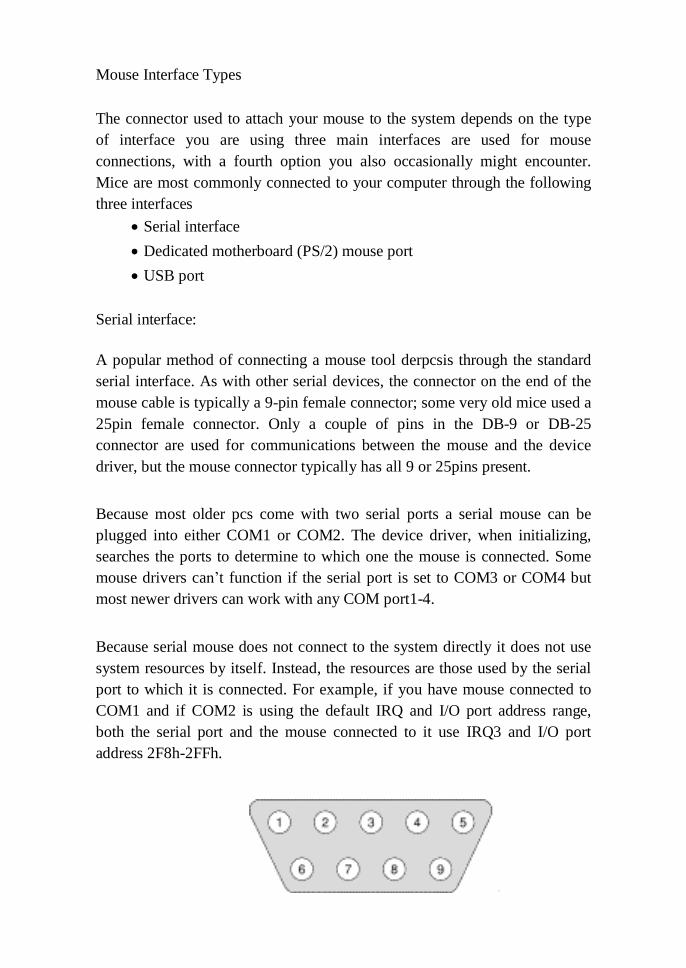
Mouse Interface Types
The connector used to attach your mouse to the system depends on the type
of interface you are using three main interfaces are used for mouse
connections, with a fourth option you also occasionally might encounter.
Mice are most commonly connected to your computer through the following
three interfaces
Serial interface
Dedicated motherboard (PS/2) mouse port
USB port
Serial interface:
A popular method of connecting a mouse tool derpcsis through the standard
serial interface. As with other serial devices, the connector on the end of the
mouse cable is typically a 9-pin female connector; some very old mice used a
25pin female connector. Only a couple of pins in the DB-9 or DB-25
connector are used for communications between the mouse and the device
driver, but the mouse connector typically has all 9 or 25pins present.
Because most older pcs come with two serial ports a serial mouse can be
plugged into either COM1 or COM2. The device driver, when initializing,
searches the ports to determine to which one the mouse is connected. Some
mouse drivers can‘t function if the serial port is set to COM3 or COM4 but
most newer drivers can work with any COM port1-4.
Because serial mouse does not connect to the system directly it does not use
system resources by itself. Instead, the resources are those used by the serial
port to which it is connected. For example, if you have mouse connected to
COM1 and if COM2 is using the default IRQ and I/O port address range,
both the serial port and the mouse connected to it use IRQ3 and I/O port
address 2F8h-2FFh.

351CS52
PS/2 mouse port:
PS/2 keyboard/mouse interface PS/2 was a type of personal computer (now
obsolete) produced by IBM in the 1980s. The interface, a mini DIN
connector, survives as the commonest connector for keyboards and mice.
The pin connections are identical for both devices and frequently the
interface may be used for either device. This feature is commonly found in
laptop computers where a full-sized keyboard or mouse may be used in
place of the native one.
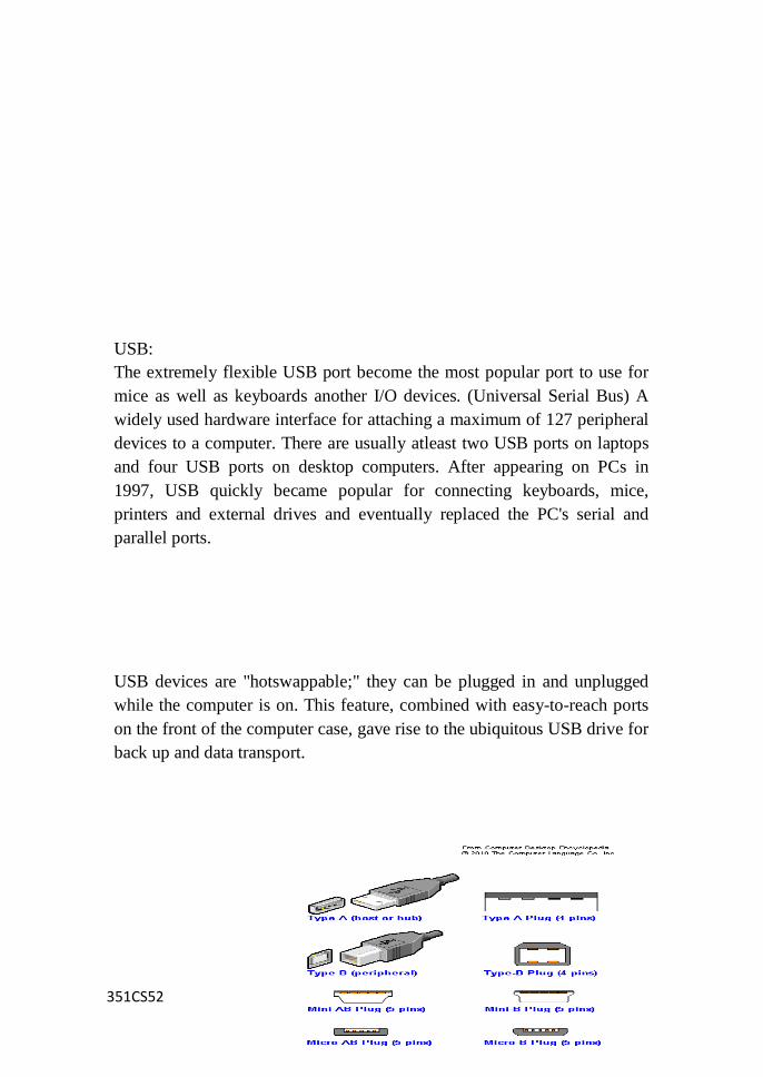
351CS52
USB:
The extremely flexible USB port become the most popular port to use for
mice as well as keyboards another I/O devices. (Universal Serial Bus) A
widely used hardware interface for attaching a maximum of 127 peripheral
devices to a computer. There are usually atleast two USB ports on laptops
and four USB ports on desktop computers. After appearing on PCs in
1997, USB quickly became popular for connecting keyboards, mice,
printers and external drives and eventually replaced the PC's serial and
parallel ports.
USB devices are "hotswappable;" they can be plugged in and unplugged
while the computer is on. This feature, combined with easy-to-reach ports
on the front of the computer case, gave rise to the ubiquitous USB drive for
back up and data transport.
351CS52
Mouse types
Different type of computer mouse has been invented to put an end to the
complicated commands in the old version of operating system. Since its
arrival the mouse has reduced the frequent use of the computer keyboard
but especially has simplified the user to access to various functions.
With this device you can track, drag, select, move files, icons and
folders…, draws pictures…navigate all over the applications of your
computer.
Memory
Memory is the electronic holding place for instructions and data that
your computer's microprocessor can reach quickly. When your
computer is in normal operation, its memory usually contains the main
parts of the operating system and some or all of the application
programs and related data that are being used. Memory is often used as
a shorter synonym for random access memory (RAM). This kind of
memory is located on one or more microchips that are physically close
to the microprocessor in your computer. The more RAM you have, the
less frequently the computer has to access instructions and data from
the more slowly accessed hard disk form of storage.

351CS52
Memory is sometimes distinguished from storage, or the physical
medium that holds the much larger amounts of data that won't fit into
RAM and may not be immediately needed there. Storage devices
include hard disks, floppy disks, CD- ROM, and tape backup systems.
The terms auxiliary storage, auxiliary memory, and secondary memory
have also been used for this kind of data repository.
Memory Chips SIMM:
A SIMM (single in-line memory module) is a module containing one or
several random access memory (RAM) chips on a small circuit
boardwith PINs that connect to the computer mother board. Since the
more RAM your computer has, the less frequently it will need to access
your secondary storage (for example, hard disk or CD-ROM), PC
owners sometimes expand RAM by installing additional SIMMs.
SIMMs typically come with a 32 data bit (36 bits counting parity bits)
path to the computer that requires a 72-pin connector. SIMMs usually
come in memory chip multiples of four megabytes.
The memory chips on a SIMM are typically dynamic RAM (DRAM)
chips. An improved form of RAM called Synchronous DRAM
(SDRAM) can also be used. Since SDRAM provides a 64 data bit path,
it requires atleast two SIMMs or a dual in-line memory module
(DIMM).
DIMM:
A DIMM (dual in-line memory module) is a double SIMM (single in-
line memory module). Like a SIMM, it's a module containing one or
several random access memory (RAM) chips on a small circuit board
with pins that connect it to the computer motherboard. A SIMM
typically has a 32 data bit (36 bits counting parity bits) path to the
computer that requires a 72-pin connector. For synchronous dynamic
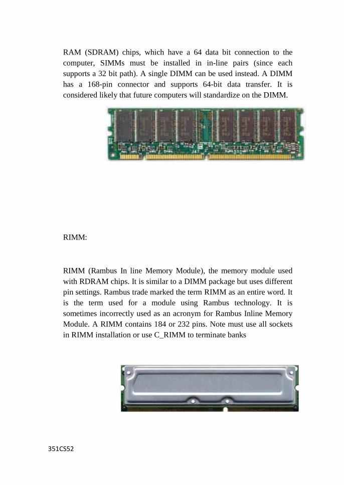
351CS52
RAM (SDRAM) chips, which have a 64 data bit connection to the
computer, SIMMs must be installed in in-line pairs (since each
supports a 32 bit path). A single DIMM can be used instead. A DIMM
has a 168-pin connector and supports 64-bit data transfer. It is
considered likely that future computers will standardize on the DIMM.
RIMM:
RIMM (Rambus In line Memory Module), the memory module used
with RDRAM chips. It is similar to a DIMM package but uses different
pin settings. Rambus trade marked the term RIMM as an entire word. It
is the term used for a module using Rambus technology. It is
sometimes incorrectly used as an acronym for Rambus Inline Memory
Module. A RIMM contains 184 or 232 pins. Note must use all sockets
in RIMM installation or use C_RIMM to terminate banks
351CS52
Cache Memory Cache on the pc:
Cache memory is very fast computer memory that is used to hold
frequently requested data and instructions. It is a little more complicated
than that, but cache exists to hold at the ready data and instructions from as
lower device (or a process that requires more time) for a faster device. On
today‘s PCs, you will commonly find cache between RAM and the CPU
and perhaps between the hard disk and RAM .A cache is any buffer storage
used to improve computer performance by reducing its access times. A
cache holds instructions and data likely to be requested by the CPU for its
next operation. Caching is used in two ways on the PC:
Cache memory
A small and very fast memory storage located between the PC‘s primary
memory (RAM) and its processor. Cache memory holds copies of
instructions and data that it gets from RAM to provide high speed access
by the processor.
Disk cache
To speed up the transfer of data and programs from the hard disk drive to
RAM, a section of primary memory or some additional memory placed on
the disk controller card is used to hold large blocks of frequently accessed
data.
SRAM and cache memory
Cache memory is usually a small amount of static random access memory
or SRAM. SRAM is made up of transistors that don‘t need to be frequently

351CS52
refreshed (unlike DRAM, which is made up of capacitors and must be
constantly refreshed).
SRAM has access speeds of 2ns (nanoseconds) or faster; this is much faster
than DRAM, which has access speeds of around 50ns. Data and
instructions stored in SRAM-based cache memory are transferred to the
CPU many times faster than if the data were transferred from the PC‘s
main memory. In case you‘re wondering why SRAM isn‘t also used for
primary memory, which could eliminate the need for cache memory all
together, there are some very good practical and economic reasons SRAM
costs as much as six times more than DRAM and to store the same amount
of data as DRAM would require a lot more space on the motherboard.
There are two types of cache memory:
Internal cache Also called primary cache; placed inside the CPU chip
External cache Also called secondary cache; located on the
motherboard
Cache is also designated by its level, which is an indication of how close to
the CPU it is. Cache is designated into two levels, with the highest level of
cache being the closest to the CPU (it is usually a part of the CPU,
in fact):
Level 1 cache: Level 1 cache is often referred to interchangeably with
internal cache, and rightly so. L1 cache is placed internally on the
processor chip and is, of course, the cache memory closest to the CPU.
Level2 cache: Level2 cache is normally placed on the motherboard very
near the CPU, but because it is further way then L1cache, it is designated
as the second level of cache. Commonly, L2 cache is considered the same
as external cache, but L2 cache can also be included on the CPU chip. If
there is a level3 to cache, it is RAM.
Extended and Expanded Memory

351CS52
Extended memory and the high memory area
All of a PC‘s memory beyond the first 1MB of RAM is called extended
memory. Every PC has limit of how much total memory it can support. The
limit is induced by the combination of the processor, motherboard, and
operating system. The width of the data and address bus is usually the basis
of the limit of how much memory the PC can address. The memory
maximum usually ranges from 16MB to 4GB, with some newer PCs now
able to accept and process even more RAM. Regardless of the amount of
RAM a PC can support, anything above 1MB is extended memory.
Extended memory is often confused with expanded memory. Expanded
memory (the upper memory area) expands conventional memory to fill up
the first 1MB of RAM. Extended memory extends RAM all the way to its
limit. The first 64KB of extended memory is reserved for use during the
startup processes of the PC. This area is called the high memory area.
The Upper Memory Area
The upper memory area was originally designated by IBM for use by the
system BIOS and video RAM, the 384KB that remains in the first 1MB of
RAM after conventional memory. As the need for more than the 640KB
available grew, this area was designated as expanded memory and special
device drivers were developed, such as EMM386.EXE, to facilitate its
general use. The use of this area frees up space in conventional memory by
relocating device drivers and TSR programs into unused space in the upper
memory area.
The main memory in a computer is called Random Access Memory. It is

351CS52
also known as RAM. This is the part of the computer that stores operating
system software, software applications and other information for the central
processing unit (CPU) to have fast and direct access when needed to
perform tasks. It is called "random access" because the CPU can go directly
to any section of main memory, and does not have go about the processin a
sequential order.
RAM is one of the faster types of memory, and has the capacity to allow
data to be read and written. When the computer is shut down, all of the
content held in RAM is purged. Main memory is available in two types:
Dynamic Random Access Memory (DRAM) and Static Random Access
Memory (SRAM).
There are several different types of memory:

351CS52
DRAM
Dynamic random access memory (DRAM) is the most common kind of
main memory in a computer. It is a prevalent memory source in PCs, as
well as workstations. Dynamic random access memory is constantly
restoring whatever information is being held in memory. It refreshes the
data by sending millions of pulses per second to the memory storage cell.
SRAM
Static Random Access Memory (SRAM) is the second type of main
memory in a computer. It is commonly used as a source of memory in
embedded devices. Data held in SRAM does not have to be continually
refreshed; information in this main memory remains as a "static image"
until it is over written or is deleted when the power is switched off. Since
SRAM is less dense and more power-efficient when it is not in use;
therefore, it is a better choice than DRAM for certain uses like memory
caches located in CPUs. Conversely, DRAM's density makes it a better
choice for main memory.
EDODRAM:
Short for Extended Data Out Dynamic Random Access Memory, a type of
DRAM that is faster than conventional DRAM. Unlike conventional
DRAM which can only access one block of data at a time, EDORAM can
start fetching the next block of memory at the same time that its ends the
previous block to the CPU.

351CS52
SDRAM:
SDRAM (synchronous DRAM) is a generic name for various kinds of
dynamic random access memory (DRAM) that are synchronized with the
clock speed that the microprocessor is optimized for. This tends to increase
the number of instructions that the processor can perform in a given time.
The speed of SDRAM is rated in MHz rather than in nanoseconds (ns).
This makes it easier to compare the bus speed and the RAM chip speed.
You can convert the RAM clock speed to nanoseconds by dividing the
chip speed into 1billion ns (which is one second). For example, an 83MHz
RAM would be equivalent to 12ns.
DDRRAM:
DDR memory, or Double Data Rate memory, is a new high performance
type of memory that runs at twice the speed of normal SDRAM. This
DDRSDRAM is ideally suited to the latest high performance processors to
increase overall system speed.
Virtual Memory Definition:
Virtual Memory is a feature of an operating system that enables a process
to use a memory (RAM) address space that is independent of other
processes running in the same system, and use a space that is larger than
the actual amount of RAM present, temporarily relegating some contents
from RAM to a disk, with little or no overhead.
In a system using virtual memory, the physical memory is divided into
equally- sized pages. The memory addressed by a process is also divided
into logical pages of the same size.
351CS52
When a process references a memory address, the memory manager fetches
from disk the page that includes the referenced address, and places it in a
vacant physical page in the RAM. Subsequent references within that
logical page are routed to the physical page. When the process references
an address from another logical page, it too is fetched into a vacant
physical page and becomes the target of subsequent similar references.
If the system does not have a free physical page, the memory manager
swaps out a logical page into the swap area-usually a paging file on disk
(in Windows XP: page file.sys), and copies (swaps in) the requested
logical page into the now-vacant physical page. The page swapped out may
belong to a different process. There are many strategies for choosing which
page is to be swapped out. (One is LRU: the Least Recently Used page is
swapped out.) If a page is swapped out and then is referenced, it is
swapped back in, from the swap area,at the expense of another page.
Virtual memory enables each process to act as if it has the whole memory
space to itself, since the addresses that it uses to reference memory are
translated by the virtual memory mechanism into different addresses in
physical memory. This allows different processes to use the same memory
addresses- the memory manager will translate references to the same
memory address by two different processes into different physical
addresses. One process generally has no way of accessing the memory of
another process. A process may use an address space larger than the
available physical memory, and each reference to an address will be
translated into an existing physical address. The bound on the amount of
memory that a process may actually address is the size of the swap area,
which may be smaller than the address able space. (A process can have an
addresss paceof4GB yet actually use only 2GB, and this can run on a
machine with a page file of 2GB.)
The size of the virtual memory on a system is smaller than the sum of the
physical RAM and the swap area, since pages that are swapped in are not
erased from the swap area, and so take up two pages of the sum of sizes.
Usually under Windows, the size of the swap area is 1.5 times the size of
the RAM.

351CS52
UNIT – III DISK DRIVES
Introduction CD:
Stands for "Compact Disc." CDs are circular discs that are 4.75 in (12
cm) in diameter. The CD standard was proposed by Sony and
Philips in 1980 and the technology was introduced to the U.S.
market in 1983. CDs can hold up to 700 MB of data or 80 minutes
of audio. The data on a CD is stored as small notches on the disc and
is read by a laser from an optical drive.
A compact disc is a small, portable, round medium made of molded
polymer (close in size to the floppy disk) for electronically
recording, storing, and playing back audio, video, text, and other
information in digital form. Tape cartridges and CDs generally
replaced the phonograph record for playing back music.
Initially, CDs were read-only, but newer technology allows users to
record as well. CDs will probably continue to be popular for music
recording and playback. A newer technology, the digital versatile disc
(DVD), stores much more in the same space and is used for playing
back movies.
Some variations of the CD include:
* CD-ROM
* CD-RW
* CD-W
* Photo CD
* Video CD
CD-ROM Definition:
A CDROM (compact disk read-only memory), also written as CD-
ROM, is a type of optical storage media that allows data to be written
to it only once.
This contrasts with memory, whose contents can be accessed (i.e.,
read and written to) at extremely high speeds but which are retained

351CS52
only temporarily (i.e., while in use or only as long as the power
supply remains on). Most storage devices and media are rewritable,
including hard disk drives (HDDs), floppy disks, USB (universal
serial bus) key drives, magnetic tape and some types of optical disks.
A CDROM consists of a thin, high-strength plastic disk which has a
special coating on one surface. This surface contains an extremely
thin spiral track that runs from near its center to close to the outer
edge. Digital data is recorded in this track in the form of a succession
of microscopic pits.
This recording is done at the factory using a stamping process in the
case of prerecorded CDROMs. It can also be done on blank
disks by individuals by burning the pits with a high precision
semiconductor laser beam on a CDROM recorder.
The standard CDROM holds 650 or 700 megabytes (MB) of
data, which, when compressed, is comparable to the data than can
be accommodated in printed books occupying several hundred feet of
shelf space.
DVDs (digital video disks or digital versatile disks) typically have a
capacity at least 4.4GB of data, roughly seven times the amount
of CDROMs. DVD technology is similar to CD technology except
that a higher precision laser is used, which makes possible a higher
recording density. As is the case with CDs, there are rewritable
DVDs and DVDs that can be written to only once (i.e., DVDROMs).
CD-ROM Data Storage
Although the disc media and the drives of the CD and CD-ROM are,
in principle, the same, there is a difference in the way data storage is
organized.
Two new sectors were defined, Mode 1 for storing computer data and
Mode 2 for compressed audio or video/graphic data.
CD-ROM Mode 1
CD-ROM Mode 1 is the mode used for CD-ROMs that carry data and
applications only. In order to access the thousands of data files that
may be present on this type of CD, precise addressing is necessary.

351CS52
Data is laid out in nearly the same way as it is on audio disks: data is
stored in sectors (the smallest separately addressable block of
information), which each hold 2,352 bytes of data, with an additional
number of bytes used for error detection and correction, as well as
control structures.
For mode 1 CD-ROM data storage, the sectors are further broken
down, and 2,048 used for the expected data, while the other 304 bytes
are devoted to extra error detection and correction code, because CD-
ROMs are not as fault tolerant as audio CDs.
There are 75 sectors per second on the disk, which yields a disc
capacity of 681,984,000 bytes (650MB) and a single speed transfer
rate of 150 KBps, with higher rates for faster CD-ROM drives.
Drive speed is expressed as multiples of the single speed transfer
rate, as 2X, 4X, 6X, and so on. Most drives support CD-ROM XA
(Extended Architecture) and Photo-CD (including multiple session
discs).
CD-ROM Mode 2
CD-ROM Mode 2 is used for compressed audio/video information
and uses only two layers of error detection and correction, the same
as the CD-DA. Therefore, all 2,336 bytes of data behind the sync
and header bytes are for user data.
Although the sectors of CD-DA, CD-ROM Mode 1 and Mode 2 are
the same size, the amount of data that can be stored varies
considerably because of the use of sync and header bytes, error
correction and detection. The Mode 2 format offers a flexible method
for storing graphics and video.
It allows different kinds of data to be mixed together, and became
the basis for CD-ROM XA. Mode 2 can be read by normal CD-
ROM drives, in conjunction with the appropriate drivers.
CD-R and CD-RW
351CS52
CD-R
DEFINITION - CD-R (for compact disc, recordable) is a type of write
once, read many (worm) compact disc (CD) format that allows one-
time recording on a disc. The CD-R (as well as the CD-RW) format
was introduced by Philips and Sony in their 1988 specification
document, the Orange Book. Prior to the release of the Orange Book,
CDs had been read-only audio (CD-Digital Audio, described in the
Red Book), to be played in CD players, and multimedia (CD-ROM),
to be played in computers' CD-ROM drives. After the Orange Book,
any user with a CD recorder drive could create their own CDs from
their desktop computers.
Like regular CDs (all the various formats are based on the original
Red Book CD-DA), CD-Rs are composed of a polycarbonate plastic
substrate, a thin reflective metal coating, and a protective outer
coating. However, in a CD-R, a layer of organic polymer dye between
the polycarbonate and metal layers serves as the recording medium.
The composition of the dye is permanently transformed by exposure
to a specific frequency of light.
Some CD-Rs have an additional protective layer to make them less
vulnerable to damage from scratches, since the data - unlike that on a
regular CD is closer to the label side of the disc. A pregrooved spiral
track helps to guide the laser for recording data, which is encoded
from the inside to the outside of the disk in a single continuous spiral.
The laser creates marks in the dye layer that mimic the reflective
properties of the pits and lands (lower and higher areas) of the
traditional CD. The distinct differences in the way the areas reflect
light register as digital data that is then unencoded for playback.
CD-R discs usually hold 74 minutes (650 MB) of data, although
some can hold up to 80 minutes (700 MB). With packet writing
software and a compatible CD-R or CD-RW drive, it is possible to
save data to a CD-R in the same way that one can save it to a floppy
disk, although - since each part of the disc can only be written once -
it is not possible to delete files and then reuse the space.
351CS52
CD-RW
DEFINITION - CD-RW (for compact disc, rewriteable) is a compact
disc (CD) format that allows repeated recording on a disc. The CD-
RW format was introduced by Hewlett-Packard, Mitsubishi, Philips,
Ricoh, and Sony, in a 1997 supplement to Philips and Sony's
Orange Book. CD-RW is Orange Book III (CD- MO was I, while
CD-R was II). Prior to the release of the Orange Book, CDs had
been read-only audio (CD-Digital Audio, described fully in the Red
Book), to be played in CD players, and multimedia (CD-ROM), to
be played in computers' CD- ROM drives.
After the Orange Book, any user with a CD Recorder drive could
create their own CDs from their desktop computers. CD-RW drives
can write both CD-R and CD-RW discs and can read any type of CD.
Like regular CDs (all the various formats are based on the original
Red Book CD-DA), CD-Rs and CD-RWs are composed of a
polycarbonate plastic substrate, a thin reflective metal coating, and a
protective outer coating. CD-R is a write once, read many (worm)
format, in which a layer of organic polymer dye between the
polycarbonate and metal layers serves as the recording medium. The
composition of the dye is permanently transformed by exposure to a
specific frequency of light.
In a CD-RW, the dye is replaced with an alloy that can change
back and forth from a crystalline form when exposed to a particular
light, through a technology called optical phase change. The patterns
created are less distinct than those of other CD formats, requiring a
more sensitive device for playback. Only drives designated as
"MultiRead" are able to read CD-RW reliably.
Similar to CD-R, the CD-RW's polycarbonate substrate is preformed
with a spiral groove to guide the laser. The alloy phase-change
recording layer, which is commonly a mix of silver, indium,
antimony, and tellurium, is sandwiched between two layers of
dielectric material that draw excess heat from the recording layer.
After heating to one particular temperature, the alloy will become
crystalline when it is cooled; after heating to a higher temperature it
will become amorphous (won't hold its shape) when it is cooled.
351CS52
By controlling the temperature of the laser, crystalline areas and non-
crystalline areas are formed. The crystalline areas will reflect the
laser, while the other areas will absorb it. The differences will
register as digital data that can be unencoded for playback. To erase
or write over recorded data, the higher temperature laser is used,
which results in the non-crystalline form, which can then be
reformed by the lower temperature laser.
CD-RW discs usually hold 74 minutes (650 MB) of data, although
some can hold up to 80 minutes (700 MB) and, according to some
reports, can be rewritten as many as 1000 times. With packet
writing software and a compatible CD-RW drive, it is possible to
save data to a CD-RW in the same way as one can save it to a floppy
disk. CD recorders (usually referred to as CD burners), were once
much too expensive for the home user, but now are similar in price to
CD-ROM drives.
Compact Disc Formats
Since the late 1970s, several Compact Disc formats were developed to
serve different purposes and uses. Starting with the CD-DA format in
1980, as a way to distribute high quality music in a compact and
convenient format, the first compact disc standard was formulated.
The idea of storing computer data on the same media, in 1983, lead
to a new format: CD-ROM. Since then, the desire to store a new
generation of multimedia content (audio, video, games, pictures,
etc.) led to new formats: CD-I, CD-XA, Photo CD, Video CD, CD+,
and others.
Compact Disc formats.
CD-DA (Red Book):
In 1979, Philips and Sony defined an architecture that became
known as the Compact Disc Digital Audio or Audio CD format.
It is the original and oldest Compact Disc standard and the
foundation for all other standards. CD-DA is an audio-only format
used on every Audio CD. The audio on these discs is usually
referred to as Red Book audio or CD-quality audio. The
specifications were published in a book with a red cover, starting
351CS52
the tradition of naming compact disc specifications by color. Index
points and variable gaps between tracks are implemented via P-Q
sub-codes.
CD+G :
This is an audio format augmented by graphics contained in the R-
W sub-codes. The R-W sub-codes encoding specifications are part of
the Red Book standard.
CD-ROM (Yellow Book):
In 1980, Philips and Sony defined the architecture that became
known as Compact Disc-Read-Only Memory. The introduction of
this architecture allowed Compact Discs to be used as an archival
medium for computer data. The Yellow Book defines more error
correction than defined by the Red Book as a small error while
playing back audio is significantly less damaging than an error in
retrieving data files.
CD-I (Green Book):
Released in 1986 to extend the definition of the Yellow Book.
The architecture defined in the Green Book helped to improve the
synchronization of data retrieval and audio information and
established the Compact Disc Interactive format. With the
introduction of CD-I, sounds could be better synchronized with
graphics than in the standards provided in Mode 2 Yellow Book.
CD-XA & CD-I Bridge (Extended Architecture):
Developed in 1991 by Microsoft, Philips, and Sony as a hybrid of the
Yellow Book and the Green Book, the CD-ROM XA standards
provide synchronized data and audio, as well as a method for the
compression of audio information. These added features improved
the usefulness of discs for multimedia purposes. Playback of these
discs required drives that could un-compress the audio. These
CD-ROM drives are designated as "XA-compatible".
CD-R/RW (Orange Book):
Defined in 1990, the major contribution of the Orange book to
CD-ROM is its foundation for CD-R technology. In addition, this
architecture allows multiple sessions to be recorded on a single
disc. Prior to the release of these standards, only one session could
be created on each disc. The unused disc space could never be
351CS52
recovered.
Photo CD:
Released in 1990 by Eastman Kodak to provide a standard for storing
high-quality images. This proprietary standard is based on CD-
ROM XA. It includes multi- session capabilities. Kodak Photo CD
discs can be read only by drives that support the CD-ROM XA
architecture.
Video CD (White Book):
Released in 1994 by JVC, Matsushita, Philips, and Sony as a
means to store movies and high-quality video presentations. This
standard is based on CD-ROM XA. It uses MPEG-1 to compress
audio and video.
Super Video CD:
Released in 1999 by Philips as an evolution of the Video CD, using
high-quality Variable Bit-Rate (VBR) MPEG-2 compression instead
of MPEG-1 featured in Video CD.
Enhanced CD/CD+ (Blue Book):
A multi-session format composed by a first session in CD-DA format
and a second session in CD-XA format. The first session contains a
regular selection of audio tracks, while the second session contains
computer data and/or video clips. Discs using this standard can be
played in a normal CD player as standard audio discs and in a
computer CD-ROM player as multimedia discs.
DVD Introduction:
DVD, also known as Digital Versatile Disc or Digital Video Disc, is
an optical disc storage media format, and was developed and
invented by Sony, and Philips in 1995. Its main uses are video and
data storage. DVDs are of the same dimensions as compact discs
(CDs), but store more than six times as much data.
Variations of the term DVD often indicate the way data is
stored on the discs: DVD-ROM (read only memory) has data that
can only be read and not written; DVD-R and DVD+R
(recordable) can record data only once, and then function as a
DVD-ROM; DVD-RW (re-writable), DVD+RW, and DVD-
RAM (random access memory) can all record and erase data multiple
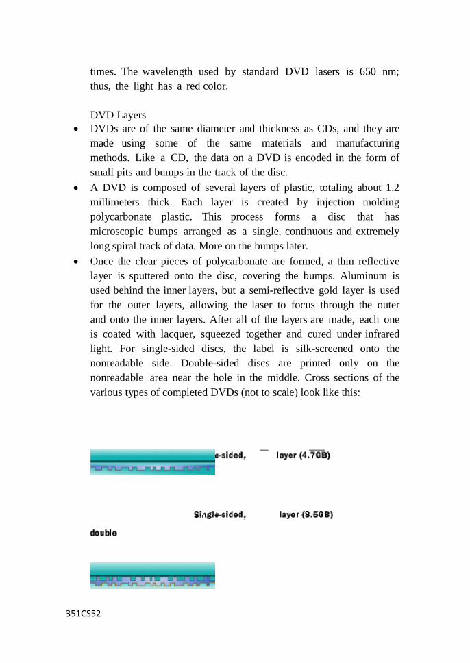
351CS52
_ _ _
times. The wavelength used by standard DVD lasers is 650 nm;
thus, the light has a red color.
DVD Layers
DVDs are of the same diameter and thickness as CDs, and they are
made using some of the same materials and manufacturing
methods. Like a CD, the data on a DVD is encoded in the form of
small pits and bumps in the track of the disc.
A DVD is composed of several layers of plastic, totaling about 1.2
millimeters thick. Each layer is created by injection molding
polycarbonate plastic. This process forms a disc that has
microscopic bumps arranged as a single, continuous and extremely
long spiral track of data. More on the bumps later.
Once the clear pieces of polycarbonate are formed, a thin reflective
layer is sputtered onto the disc, covering the bumps. Aluminum is
used behind the inner layers, but a semi-reflective gold layer is used
for the outer layers, allowing the laser to focus through the outer
and onto the inner layers. After all of the layers are made, each one
is coated with lacquer, squeezed together and cured under infrared
light. For single-sided discs, the label is silk-screened onto the
nonreadable side. Double-sided discs are printed only on the
nonreadable area near the hole in the middle. Cross sections of the
various types of completed DVDs (not to scale) look like this:

351CS52
DVD-Audio
DVD-Audio (DVD-A) is a DVD format developed by Panasonic
that is specifically designed to hold audio data, and particularly, high-
quality music. The DVD Forum released the final DVD-A
specification in March of 1999. The new DVD format is said to
provide at least twice the sound quality of audio CD on disks that
can contain up to seven times as much information. Various types
of DVD-A-compatible DVD players are being manufactured, in
addition to the DVD-A players specifically developed for the format.
Almost all of the space on a DVD video disc is devoted to
containing video data. As a consequence, the space allotted to audio
data, such as a Dolby Digital 5.1 soundtrack, is severely limited. A
lossy compression technique - so-called because some of the data is
lost - is used to enable audio information to be stored in the available
space, both on standard CDs and DVD-Video disks.
In addition to using lossless compression methods, DVD-A also
provides more complexity of sound by increasing the sampling
rate and the frequency range beyond what is possible for the space
limitations of CDs and DVD-Video. DVD-Audio is 24-bit, with a
sampling rate of 96kHz; in comparison, DVD-Video soundtrack is
16-bit, with a sampling rate of 48kHz, and standard audio CD is
16-bit, with a sampling rate of 44.1kHz.
Although DVD-A is designed for music, it can also contain other
data, so that - similarly to Enhanced CD - it can provide the
listener with extra information, such as liner notes, and images. A
variation on the format, DVD- AudioV, is designed to hold a
limited amount of conventional DVD video data in addition to
DVD-Audio. DVD-A is backed by most of the industry as the
technology that will replace the standard audio CD.
The major exceptions are Philips and Sony, whose Super Audio
provides similar audio quality. Like DVD-A, SACD offers 5.1
channel surround sound in addition to 2-channel stereo. Both
formats improve the complexity of sound by increasing bit rates
and sampling frequencies (among other techniques), and can be
played on existing CD players, although only at quality levels similar
351CS52
to those of traditional CDs.
DVD-Video
DVD-video which was launched in 1997, in USA has become the
most successful of all the DVD formats. It has proved to be an
ideal media to distribute video content. It can store a full length
movie (113 minutes) in high quality video with surround sound
audio on a disc, the same size as CD. In order to fit studio quality
films onto DVD discs some form of compression must be used.
Direct transfer of movie to DVD needs data transfer rate of 200 Mb
whereas maximum data rate for DVD is 9.8 Mb per second. MPEG-
1 compression can be used but MPEG-2 gives higher quality and
has become the standard compression for DVD-video. A decoder is
needed to decode the MPEG-2 compression and playback the
encoded video system.
DVD-video authoring software bring together images, video and
sound to playback on a DVD-video player. Sonic 'DVD creator',
Apple DVD-studio pro' are few authoring softwares. To view a
DVD-video, the user needs a DVD-video, a DVD video player or a
DVD-ROM drive equipped with an MPEG2 decoder.
Making CD
The making of a CD includes 2 main steps: Pre-mastering and
Mastering.
Pre-mastering involves data preparation for recording. The data is
indexed, organized, re-formatted (possibly with some ECC), and
transferred to magnetic tape. Now, the data is ready to be
imprinted onto the CD. Mastering involves physical transfer of the
data into the pits and lands.
First, a layer of light-sensitive photoresist is spin-coated onto the
clean glass master-disk from a solvent solution.
Then, the photoresist is exposed to a modulated beam of a short-
wavelength light, which carries the encoded data. Next, the master
is developed in a wet process by exposing it to the developer,
which etches away exposed areas thus leaving the same pattern we

351CS52
will find later on the CD. Next, the master is coated (using
electroplating technique) with a thick (about 300 um) metal layer to
form a stamper - a negative replica of the disk. The photoresist layer
is destroyed during this process, but the much more durable stamper
is formed and can be used for CD replication. Usually, a stamper
can be used to produce a few tens of thousands CDs before it
wears out.
Finally, the process of injection molding is used to produce a
surface of the compact disk. Hot plastic (PC) is injected into a mold,
and then is pressed against the stamper and cooled, resulting in the
CD. Other processes than injection molding could be used, but
they all involve pressing the hot plastic against the stamper.
At the very end, the pits and lands on the surface of a CD are coated
with a thin reflective metal layer (aluminum), then coated with
lacquer and supplied with the label. Packaging usually finishes the
process of making a CD.
Hard disk drive:
A hard disk drive (often shortened as "hard disk" or "hard
drive"), is a non- volatile storage device which stores digitally
encoded data on rapidly rotating platters with magnetic surfaces.
Strictly speaking, "drive" refers to a device distinct from its medium,
such as a tape drive and its tape, or a floppy disk drive and its
floppy disk. Early HDDs had removable media; however, an HDD
today is typically a sealed unit (except for a filtered vent hole to
equalize air pressure) with fixed media.
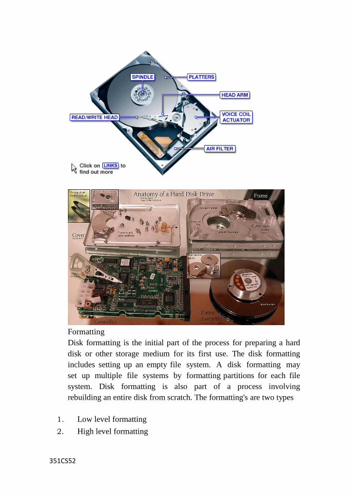
351CS52
Formatting
Disk formatting is the initial part of the process for preparing a hard
disk or other storage medium for its first use. The disk formatting
includes setting up an empty file system. A disk formatting may
set up multiple file systems by formatting partitions for each file
system. Disk formatting is also part of a process involving
rebuilding an entire disk from scratch. The formatting's are two types
1. Low level formatting
2. High level formatting
351CS52
Low level formatting:
To find out if a drive is low level formatted or not the DOS FDISK
program is used. If the FDISK program recognizes the hard disk
drive, then the driveTo level format a drive the easiest method is to
call the BIOS interrupt INT 13h, function 05h. The BIOS will
convert this function call into proper CCB(Command Control
Block), i.e.set of commands for the drive controller, and send
these command code bytes to the proper I/O port connected to
the disk controller
High-level formatting:
After the low level formatting and partitioning, the final step for
preparing the hard disk drive for use is to high level format the drive. The
drive is already divided into tracks and sectors by the low level
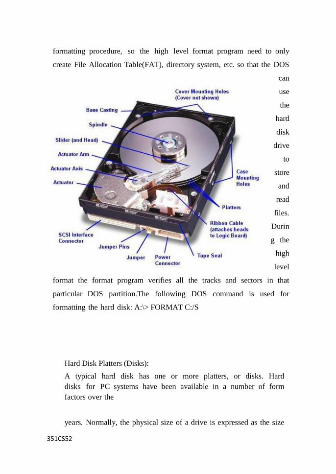
351CS52
formatting procedure, so the high level format program need to only
create File Allocation Table(FAT), directory system, etc. so that the DOS
can
use
the
hard
disk
drive
to
store
and
read
files.
Durin
g the
high
level
format the format program verifies all the tracks and sectors in that
particular DOS partition.The following DOS command is used for
formatting the hard disk: A:\> FORMAT C:/S
Hard Disk Platters (Disks):
A typical hard disk has one or more platters, or disks. Hard
disks for PC systems have been available in a number of form
factors over the
years. Normally, the physical size of a drive is expressed as the size
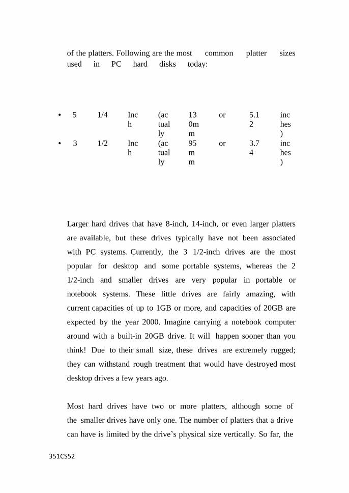
351CS52
of the platters. Following are the most common platter sizes
used in PC hard disks today:
Larger hard drives that have 8-inch, 14-inch, or even larger platters
are available, but these drives typically have not been associated
with PC systems. Currently, the 3 1/2-inch drives are the most
popular for desktop and some portable systems, whereas the 2
1/2-inch and smaller drives are very popular in portable or
notebook systems. These little drives are fairly amazing, with
current capacities of up to 1GB or more, and capacities of 20GB are
expected by the year 2000. Imagine carrying a notebook computer
around with a built-in 20GB drive. It will happen sooner than you
think! Due to their small size, these drives are extremely rugged;
they can withstand rough treatment that would have destroyed most
desktop drives a few years ago.
Most hard drives have two or more platters, although some of
the smaller drives have only one. The number of platters that a drive
can have is limited by the drive‘s physical size vertically. So far, the
• 5 1/4 Inc
h
(ac
tual
ly
13
0m
m
or 5.1
2
inc
hes
)
• 3 1/2 Inc
h
(ac
tual
ly
95
m
m
or 3.7
4
inc
hes
)
351CS52
maximum number of platters that I have seen in any 3.5-inch drive is
11.
Platters traditionally have been made from an aluminum alloy for
strength and light weight. With manufacturers‘ desire for higher and
higher densities and smaller drives, many drives now use platters
made of glass (or, more technically, a glass-ceramic composite).
One such material is called MemCor, which is produced by the
Dow Corning Corporation. MemCor is composed of glass with
ceramic implants, which resists cracking better than pure glass.
Glass platters offer greater rigidity and, therefore, can be machined to
one-half the thickness of conventional aluminum disks, or less.
Glass platters also are much more thermally stable than aluminum
platters, which means that they do not change dimensions (expand
or contract) very much with any changes in temperature. Several
hard disks made by companies such as Seagate, Toshiba, Areal
Technology, Maxtor, and Hewlett-Packard currently use glass or
glass-ceramic platters.
Read Write Head:
The RW head is the key component that performs the reading
and writing functions. It is placed on a slider which is in term
connected to an actuator arm which allow the RW head to access
various parts of the platter during data IO functions by sliding
across the spinning platter. The sliding motion is derived by passing
a current through the coil which is part of the actuator-assembly. As
the coil is placed between two magnets, the forward or backward
sliding motion is hence derived by simple current reversal. This
351CS52
location of the platter (just like the landmark along the road) is
identified and made possible by the embedded servo code written on
the platter.
Recording Media:
No matter what substrate is used, the platters are covered with a thin
layer of a magnetically retentive substance called media in which
magnetic information is stored. Two popular types of media
are used on hard disk platters:
Oxide media
Thin-film media
Oxide media is made of various compounds, containing iron oxide as
the active ingredient. A magnetic layer is created by coating the
aluminum platter with a syrup containing iron-oxide particles.
This media is spread across the disk by spinning the platters at
high speed. Centrifugal force causes the material to flow from the
center of the platter to the outside, creating an even coating of
media material on the platter. The surface then is cured and polished.
Finally, a layer of material that protects and lubricates the surface is
added and burnished smooth. The oxide media coating normally is
about 30 millionths of an inch thick.
As drive density increases, the media needs to be thinner and more
perfectly formed. The capabilities of oxide coatings have been
exceeded by most higher- capacity drives. Because oxide media is
very soft, disks that use this type of media are subject to head-crash
damage if the drive is jolted during operation. Most older drives,
especially those sold as low-end models, have oxide media on
the drive platters. Oxide media, which has been used since 1955,
remained popular because of its relatively low cost and ease of
application. Today, however, very few drives use oxide media.
Thin-film media is thinner, harder, and more perfectly formed
than oxide media. Thin film was developed as a high-performance
351CS52
media that enabled a new generation of drives to have lower head
floating heights, which in turn made possible increases in drive
density. Originally, thin-film media was used only in higher-
capacity or higher-quality drive systems, but today, virtually all
drives have thin-film media.
Head Actuator Mechanisms:
Possibly more important than the heads themselves is the mechanical
system that moves them: the head actuator. This mechanism moves
the heads across the disk and positions them accurately above the
desired cylinder. Many variations on head actuator mechanisms are
in use, but all of them can be categorized as being one of two basic
types:
• Stepper motor actuators
• Voice-coil actuators
The use of one or the other type of positioner has profound effects
on a drive's performance and reliability. The effect is not limited
to speed; it also includes accuracy, sensitivity to temperature,
position, vibration, and overall reliability. To put it bluntly, a drive
equipped with a stepper motor actuator is much less reliable (by a
large factor) than a drive equipped with a voice-coil
actuator.
The head actuator is the single most important specification in the
drive. The type of head actuator mechanism in a drive tells you a
great deal about the drive's performance and reliability characteristics.
Voice coil actuator:
A voice-coil actuator with servo control is not affected by temperature
changes, as a stepper motor is. When the temperature is cold and the
platters have shrunk (or when the temperature is hot and the platters
have expanded), the voice-coil system compensates because it never
positions the heads in predetermined track positions. Rather, the
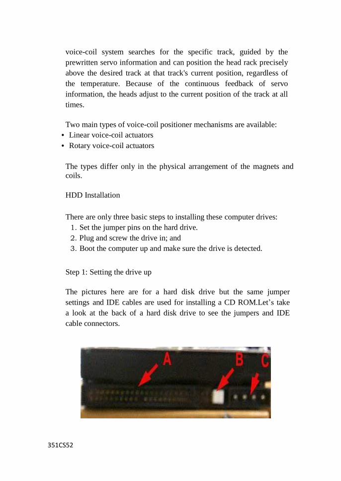
351CS52
voice-coil system searches for the specific track, guided by the
prewritten servo information and can position the head rack precisely
above the desired track at that track's current position, regardless of
the temperature. Because of the continuous feedback of servo
information, the heads adjust to the current position of the track at all
times.
Two main types of voice-coil positioner mechanisms are available:
• Linear voice-coil actuators
• Rotary voice-coil actuators
The types differ only in the physical arrangement of the magnets and
coils.
HDD Installation
There are only three basic steps to installing these computer drives:
1. Set the jumper pins on the hard drive.
2. Plug and screw the drive in; and
3. Boot the computer up and make sure the drive is detected.
Step 1: Setting the drive up
The pictures here are for a hard disk drive but the same jumper
settings and IDE cables are used for installing a CD ROM.Let‘s take
a look at the back of a hard disk drive to see the jumpers and IDE
cable connectors.
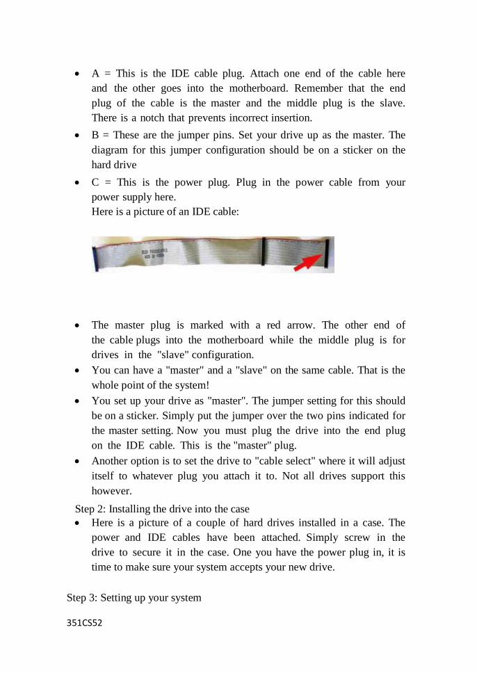
351CS52
A = This is the IDE cable plug. Attach one end of the cable here
and the other goes into the motherboard. Remember that the end
plug of the cable is the master and the middle plug is the slave.
There is a notch that prevents incorrect insertion.
B = These are the jumper pins. Set your drive up as the master. The
diagram for this jumper configuration should be on a sticker on the
hard drive
C = This is the power plug. Plug in the power cable from your
power supply here.
Here is a picture of an IDE cable:
The master plug is marked with a red arrow. The other end of
the cable plugs into the motherboard while the middle plug is for
drives in the "slave" configuration.
You can have a "master" and a "slave" on the same cable. That is the
whole point of the system!
You set up your drive as "master". The jumper setting for this should
be on a sticker. Simply put the jumper over the two pins indicated for
the master setting. Now you must plug the drive into the end plug
on the IDE cable. This is the "master" plug.
Another option is to set the drive to "cable select" where it will adjust
itself to whatever plug you attach it to. Not all drives support this
however.
Step 2: Installing the drive into the case
Here is a picture of a couple of hard drives installed in a case. The
power and IDE cables have been attached. Simply screw in the
drive to secure it in the case. One you have the power plug in, it is
time to make sure your system accepts your new drive.
Step 3: Setting up your system
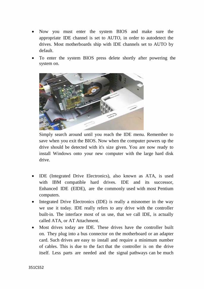
351CS52
Now you must enter the system BIOS and make sure the
appropriate IDE channel is set to AUTO, in order to autodetect the
drives. Most motherboards ship with IDE channels set to AUTO by
default.
To enter the system BIOS press delete shortly after powering the
system on.
Simply search around until you reach the IDE menu. Remember to
save when you exit the BIOS. Now when the computer powers up the
drive should be detected with it's size given. You are now ready to
install Windows onto your new computer with the large hard disk
drive.
IDE (Integrated Drive Electronics), also known as ATA, is used
with IBM compatible hard drives. IDE and its successor,
Enhanced IDE (EIDE), are the commonly used with most Pentium
computers.
Integrated Drive Electronics (IDE) is really a misnomer in the way
we use it today. IDE really refers to any drive with the controller
built-in. The interface most of us use, that we call IDE, is actually
called ATA, or AT Attachment.
Most drives today are IDE. These drives have the controller built
on. They plug into a bus connector on the motherboard or an adapter
card. Such drives are easy to install and require a minimum number
of cables. This is due to the fact that the controller is on the drive
itself. Less parts are needed and the signal pathways can be much

351CS52
shorter.
These short signal pathways improve reliability of the drive.
Before, data could lose its integrity while traveling over cheap ribbon
cables. Lastly, integrating the controller is easier on the
manufacturer because they do not have to worry about complying
with another manufacturer‘s controller. Each drive is an
independent entity.
The IDE specification has evolved quite a bit since it was first
released in the 1980‘s. It is short for Integrated Drive Electronics.
ATA, or AT Attachment, also goes hand-in-hand with IDE, since
they are basically the same concept. The basic concept is that the
drive‘s controller is integrated onto the device itself rather than having
a separate controller.
This reduces cost and also makes firmware updates easier since there
is no cross-manufacturer complexity. While ATA refers to the
drive itself and how it operates, IDE refers to the type of interface
connector (40 pin in this case) as well as the type of controller.
E IDE :
Short for Enhanced IDE, a newer version of the IDE mass storage
device interface standard developed by Western Digital
Corporation. It supports data rates of between 4 and 16.6 MBps,
about three to four times faster than the old IDE standard. In
addition, it can support mass storage devices of up to 8.4
gigabytes, whereas the old standard was limited to 528 MB. Because
of its lower cost, enhanced EIDE has replaced SCSI in many areas.
EIDE is sometimes referred to as Fast ATA or Fast IDE, which is
essentially the same standard, developed and promoted by Seagate
Technologies. It is also sometimes called ATA-2.
There are four EIDE modes defined. The most common is Mode
4, which supports transfer rates of 16.6 MBps. There is also a new
mode, called ATA-3 or Ultra ATA, that supports transfer rates of 33
MBps.
351CS52
Advantages of RAID
There are three primary reasons that RAID was implemented:
* Redundancy
* Increased Performance
* Lower Costs
Redundancy is the most important factor in the development of
RAID for server environments. This allowed for a form of backup of
the data in the storage array in the event of a failure. If one of the
drives in the array failed, it could either be swapped out for a new
drive without turning the systems off (referred to as hot swappable)
or the redundant drive could be used. The method of redundancy
depends on which version of RAID is used.
The increased performance is only found when specific versions of
the RAID are used. Performance will also be dependent upon the
number of drives used in the array and the controller.
All managers of IT departments like low costs. When the RAID
standards were being developed, cost was also a key issue. The
point of a RAID array is to provide the same or greater storage
capacity for a system compared to using individual high capacity
hard drives. A good example of this can be seen in the price
differences between the highest capacity hard drives and lower
capacity drives. Three drives of a smaller size could cost less
than an individual high- capacity drive but provide more capacity.
Conclusions
Overall RAID provides systems with a variety of benefits depending
upon the version implemented. Most consumer users will likely opt
to use the RAID 0 for increased performance without the loss of
storage space. This is primarily because redundancy is not an issue
for the average user. In fact, most computer systems will only offer
either RAID 0 or 1. The costs of implementing a RAID 0+1 or RAID
5 system generally are too expensive for the average consumer and
are only found in high-end workstation or server level systems.
351CS52
RAID (redundant array of independent disks; originally redundant
array of inexpensive disks) is a way of storing the same data in
different places (thus, redundantly) on multiple hard disks. By
placing data on multiple disks, I/O (input/output) operations can
overlap in a balanced way, improving performance. Since multiple
disks increases the mean time between failures (MTBF), storing data
redundantly also increases fault tolerance.
A RAID appears to the operating system to be a single logical hard
disk. RAID employs the technique of disk striping, which involves
partitioning each drive's storage space into units ranging from a
sector (512 bytes) up to several megabytes. The stripes of all the disks
are interleaved and addressed in order.
RAID Configuration Levels
The industry currently has agreed upon six RAID configuration
levels and designated them as RAID 0 through RAID 5. Each RAID
level is designed for speed, data protection, or a combination of both.
The RAID levels are:
RAID - 0 Data striping Array
RAID - 1 Mirrored Disk Array
RAID - 2 Parallel Array, Hamming Code
RAID - 3 Parallel Array with Parity
RAID - 4 Independent Actuators with a dedicated Parity Drive
RAID - 5 Independent Actuators with parity spread
across all drives
The most popular RAID levels are RAID-0, RAID-1, and
RAID-5.

351CS52
SCSI
SCSI (pronounced scuzzy), the Small
Computer System Interface, is a set of
ANSI standard electronic interfaces
that allow personal computers to
communicate with peripheral hardware
such as disk drives, tape drives, CD-
ROM drives, printers, and scanners
faster and more flexibly than previous
interfaces. Developed at Apple
Computer and still used in the
Macintosh, the present set of SCSIs are
parallel interfaces. SCSI ports continue
to be built into many personal
computers today and are supported by
all major operating systems.
In addition to faster data rates, SCSI is more flexible than earlier
parallel data transfer interfaces. The latest SCSI standard, Ultra-2
SCSI for a 16-bit bus can transfer data at up to 80 megabytes per
second (MBps).SCSI allows up to 7 or 15 devices (depending on the
bus width) to be connected to a single SCSI port in daisy-chain
fashion. This allows one circuit board orcard to accommodate all the
peripherals, rather than having a separate card for each device, making
it an ideal interface for use with portable and notebook computers. A
single host adapter, in the form of a PC Card, can serve as a SCSI
interface for a laptop, freeing up the parallel and serial ports for use
with an external modem and printer while allowing other devices to
be used in addition.
Although not all devices support all levels of SCSI, the evolving
SCSI standards are generally backwards-compatible. That is, if
you attach an older device to a newer computer with support for a
later standard, the older device will work at the older and slower data
351CS52
rate.
The original SCSI, now known as SCSI-1, evolved into SCSI-2,
known as "plain SCSI." as it became widely supported. SCSI-3
consists of a set of primary commands and additional specialized
command sets to meet the needs of specific device types. The
collection of SCSI-3 command sets is used not only for the SCSI- 3
parallel interface but for additional parallel and serial protocols,
including Fibre Channel, Serial Bus Protocol (used with the IEEE
1394 FireWire physical protocol), and the Serial Storage Protocol
(SSP).
A widely implemented SCSI standard is Ultra-2 (sometimes spelled
"Ultra2") which uses a 40 MHz clock rate to get maximum data
transfer rates up to 80 MBps. It provides a longer possible cabling
distance (up to 12 meters) by using low voltage differential (LVD)
signaling. Earlier forms of SCSIs use a single wire that ends in a
terminator with a ground. Ultra-2 SCSI sends the signal over two
wires with the data represented as the difference in voltage between
the two wires. This allows support for longer cables. A low
voltage differential reduces power requirements and manufacturing
costs.
The latest SCSI standard is Ultra-3 (sometimes spelled
"Ultra3")which increases the maximum burst rate from 80 Mbps to
160 Mbps by being able to operate at the full clock rate rather
than the half-clock rate of Ultra-2. The standard is also sometimes
referred to as Ultra160/m. New disk drives supporting Ultra160/m
will offer much faster data transfer rates. Ultra160/m also includes
cyclical redundancy checking (CRC) for ensuring the integrity of
transferred data and domain validation for testing the SCSI network.
The following varieties of SCSI are currently implemented:
SCSI-1: Uses an 8-bit bus, and supports data rates of 4 MBps
SCSI-2: Same as SCSI-1, but uses a 50-pin connector instead of a
25-pin connector, and supports multiple devices. This is what most
people mean when they refer to plain SCSI.
Wide SCSI: Uses a wider cable (168 cable lines to 68 pins) to support
351CS52
16-bit transfers.
Fast SCSI: Uses an 8-bit bus, but doubles the clock rate to support
data rates of 10 MBps.
Fast Wide SCSI: Uses a 16-bit bus and supports data rates of 20 MBps.
Ultra SCSI: Uses an 8-bit bus, and supports data rates of 20 MBps.
SCSI-3: Uses a 16-bit bus and supports data rates of 40 MBps. Also
called Ultra Wide SCSI.
Ultra2 SCSI: Uses an 8-bit bus and supports data rates of 40 MBps.
Wide Ultra2 SCSI: Uses a 16-bit bus and supports data rates of 80
MBps Ultra ATA and Serial ATA
Serial ATA :
Serial ATA (SATA) is an IDE standard for connecting devices
like optical drives and hard drives to the motherboard. The term
SATA generally refers to the types of cables and connections that
follow this standard.
SATA cables are long, thin, 7-pin cables. One end plugs into a port
on the motherboard, usually labeled SATA, and the other into the
back of a storage device like a hard drive.
Serial ATA replaces Parallel ATA as the IDE standard of choice
for connecting storage devices inside of a computer. SATA storage
devices can transmit data to and from the rest of the computer
over twice as fast as an otherwise similar PATA device.
A serial ATA provides a high-speed connection and uses point-to-
point technology to ensure efficient communication between two
devices.
The serial ATA was designed to replace the parallel ATA interface.
The Serial ATA International Organization is responsible for the
development and maintenance of the serial ATA.
Ultra ATA:
In the second half of 1997 EIDE's 16.6 MBps limit was doubled to
33 MBps by the new Ultra ATA (also referred to as ATA-33 or
Ultra DMA mode 2 protocol). As well as increasing the data transfer
rate, Ultra ATA also improved data integrity by using a data transfer
error detection code called Cyclical Redundancy Check (CRC).
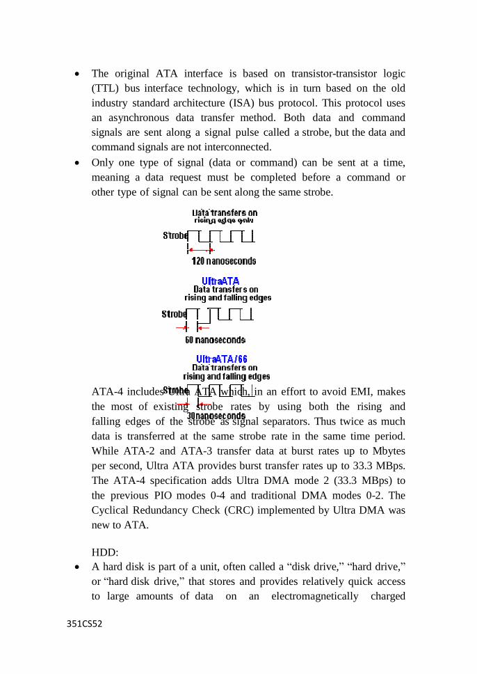
351CS52
The original ATA interface is based on transistor-transistor logic
(TTL) bus interface technology, which is in turn based on the old
industry standard architecture (ISA) bus protocol. This protocol uses
an asynchronous data transfer method. Both data and command
signals are sent along a signal pulse called a strobe, but the data and
command signals are not interconnected.
Only one type of signal (data or command) can be sent at a time,
meaning a data request must be completed before a command or
other type of signal can be sent along the same strobe.
ATA-4 includes Ultra ATA which, in an effort to avoid EMI, makes
the most of existing strobe rates by using both the rising and
falling edges of the strobe as signal separators. Thus twice as much
data is transferred at the same strobe rate in the same time period.
While ATA-2 and ATA-3 transfer data at burst rates up to Mbytes
per second, Ultra ATA provides burst transfer rates up to 33.3 MBps.
The ATA-4 specification adds Ultra DMA mode 2 (33.3 MBps) to
the previous PIO modes 0-4 and traditional DMA modes 0-2. The
Cyclical Redundancy Check (CRC) implemented by Ultra DMA was
new to ATA.
HDD:
A hard disk is part of a unit, often called a ―disk drive,‖ ―hard drive,‖
or ―hard disk drive,‖ that stores and provides relatively quick access
to large amounts of data on an electromagnetically charged
351CS52
surface or set of surfaces. Today‘s computers typically come
with a hard disk that contains several billion bytes (gigabytes) of
storage.
A hard disk drive (HDD, also commonly shortened to hard drive and
formerly known as a fixed disk) is a digitally encoded non-volatile
storage device which stores data on rapidly rotating platters with
magnetic surfaces. Strictly speaking, ―drive‖ refers to an entire unit
containing multiple platters, a read/write head assembly, driver
electronics, and motor while ―hard disk‖ (sometimes ―platter‖)
refers to the storage medium itself.
Hard disks were originally developed for use with computers. In
the 21st century, applications for hard disks have expanded beyond
computers to include video recorders, audio players, digital
organizers, and digital cameras. In 2005 the first cellular telephones
to include hard disks were introduced by Samsung and Nokia.
A hard disk is really a set of stacked ―disks,‖ each of which, like
phonograph records, has data recorded electromagnetically in
concentric circles or ―tracks‖ on the disk. A ―head‖ (something like
a phonograph arm but in a relatively fixed position) records
(writes) or reads the information on the tracks. Two heads, one on
each side of a disk, read or write the data as the disk spins. Each read
or write operation requires that data be located, which is an
operation called a ―seek.‖ (Data already in a disk cache, however,
will be located more quickly.)
A hard disk/drive unit comes with a set rotation speed varying from
4500 to 7200 rpm. Disk access time is measured in milliseconds.
Although the physical location can be identified with cylinder,
track, and sector locations, these are actually mapped to a logical
block address (LBA) that works with the larger address range on
today‘s hard disks.
Partition Definition:
In personal computers, a partition is a logical division of a hard disk
created so that you can have different operating systems on the
same hard disk or to create the appearance of having separate hard

351CS52
drives for file management, multiple users, or other purposes. A
partition is created when you format the hard disk. Typically, a one-
partition hard disk is labelled the "C:" drive ("A:" and "B:" are
typically reserved for diskette drives). A two-partition hard drive
would typically contain "C:" and "D:" drives. (CD-ROM drives
typically are assigned the last letter in whatever sequence of letters
have been used as a result of hard disk formatting, or typically with a
two-partition, the "E:" drive.)
When you boot an operating system into your computer, a critical part
of the process is to give control to the first sector on your hard
disk. It includes a partition table that defines how many partitions
the hard disk is formatted into, the size of each, and the address
where each partition begins. This sector also contains a program
that reads in the boot sector for the operating system and gives it
control so that the rest of the operating system can be loaded into
random access memory.
Boot viruses can put the wrong information in the partition sector
so that your operating system can't be located. For this reason, you
should have a back- up version of your partition sector on a diskette
known as a bootable floppy.
Troubleshoot Hard Disk Drive Problems General Information:
If your computer is operating but has a problem such as "cannot read
sectors" or in general shows a "retry, abort, ignore" error while
reading the drive, it is an indication that there are some bad spots on
the drive. These bad spots normally are fixed by reformatting the hard
drive. This is a big hassle since all the programs will have to be
reloaded and unless you back up and restore your data, you will
loose ALL the data stored on the hard drive.
351CS52
Meanwhile, here are some troubleshooting instructions
1. There is some type of electrical connection problem
2. The hard drive controller has failed
3. The hard drive has failed physically
4. The hard drive has failed electronically
5. There is a problem with the recording on the hard drive
6. The CMOS settings are not correctly set
7. There is a conflict with the IRQ settings
8. There is a conflict with the jumper settings
9. The drive is unable to boot.
10. Fdisk reports wrong size when using drives larger than 64GB.
1. There is some type of electrical connection problem
Make sure the cable connections are correct. Check the 4-
wire connector that carries power and make sure it is properly
plugged in. This connector has a taper on one end and cannot
be put on backwards.
When power is first applied to the computer, the hard drive light
will momentarily come on which is a good indication that the drive
is getting power. Also the vibration of the spinning platter and the
slight hum will verify that the drive is plugged in.
Next check the data ribbon cable. This cable is a flat cable with
a one edge colored red or blue to indicate the location of pin 1.
Some of these cables are also keyed by having a small tab in the
center of the connector's edge. On many hard drives pin 1 is the pin
closest to the power supply connection, but not always, so check the
hard drive documentation or look on this site in Hard Drives and
locate your model.
If all the cables are connected properly, and power is applied, you
should be able to hear and feel the drive spinning. If the drive is not
spinning, turn off the power and try using a different power plug
(maybe the one that the CD-ROM is connected). If the drive
is not spinning then it is probably bad.

351CS52
2. The hard drive controller has failed
A controller failure is usually indicated by an error at boot up. There is
not much that can be done except to replace the hard drive. See
hard drive error codes
3. The hard drive has failed physically
There can be two indications for this condition.
1) The drive is not spinning. To troubleshoot this condition you need
to physically access the drive while the computer is on. With the cover
off, look at the drive and find the side which has NO components.
With your hand touch that side and try to feel the spinning of the
hard drive platter. A typical hard drive has a small amount of
vibration and a slight whine.
2) The hard drive head has crashed onto the platter. This usually
causes the drive to emit unusual sounds sometimes grinding and
many times repeating on a regular basis. A normal hard drive has a
smooth whine so its should be easy to identify the bad drive by just
listening.
4. The hard drive has failed electronically
This will be indicated by an error message during the computer boot
cycle. Not much can be done in this condition other then
replace the drive.
5. There is a problem with the recording on the hard drive (read
or write)
There are two conditions that can cause this problem.
1) The hard drive is unable to read a sector on the platter.
This problem can be identified by running a program that is capable
in performing a hard drive surface test. In Windows 95 you can
351CS52
use the scandisk which is found in the
Start/Programs/Accessories/System Tools folder. Another way is to
use a utility program like Norton Utilities to perform the surface scan.
This problem can also be seen when you are formatting the hard
drive and is indicated as "bad sectors" during the formatting. These
bad sectors are normally recorded as such by the format program and
the computer knows not to use them but more bad sectors can be
created as the hard drive ages.
2) One or more files have been damaged by some process.
These type or problems are caused when the computer is unexpectedly
rebooted after a lock-up or perhaps a power failure. They are easy
to troubleshoot and repair.
Simply run the scandisk program which is found in the
Start/Programs/Accessories/System Tools folder and allow the
computer to repair any errors found.
After such a repair it is very possible that one of more files were
corrupted and are now unusable. It is impossible to tell which files
will be affected in advance but if you write down the bad file names
shown during the scan disk operation you can try to find the
application which loaded them and re-install that application.
The CMOS settings are not correctly set Check the CMOS settings.
These settings must match the required settings of the manufacturer.
a) older computers
On these computers you have to go into the CMOS/BIOS during
boot and change the setting by selecting a number from 1 to 48, by
selecting a TYPE number of 1 or 2, or by selected the setting "User
defined" and manually entering the hard drive parameters of "head",
"cylinders", "spt", "WP", and "LZ". These settings can be found on
your hard drive users manual, on the manufacturer's web site, or on
351CS52
this site by looking for the company, then the hard drive's model
number.
After entering these parameters you will normally save them before
exiting the BIOS program and then reboot the computer.
b) newer computers
On these computers you can almost always find a selection that
allows the computer to "Automatically" find IDE style hard drives.
There are two methods in use. First you can select "Auto" from the
main BIOS screen for the drive C: D: E: or F:. After rebooting the
drive will be automatically detected. Second, some Bios types have a
selection called "Detect hard drive" which allows you to initiate a
detection process which looks for a drive, presents you with the
drive found and gives you the option of accepting or rejecting the
detected drive. This process is repeated for each of the available
drive assignments C D E and F.
Again you must save the BIOS changes and reboot the computer.
Very critical also is the LBA setting which can cause the drive to
operate but not be able to see all the data. This comes into play with
drives larger than 500 megabytes and is found by entering the
computer BIOS at boot up and looking in the area where the hard
drive is configured.
Solution:
The LBA setting in the BIOS is not correct. Most likely on drives that
are more than 528MB, the LBA setting is not enabled. Enter the BIOS
and enable the LBA.
This can happen very easily when a drive is on a computer and
works fine but then the motherboard is changed. The old BIOS had
LBA enabled but the new one might not. After the drive
is installed it seems to work
6. There is a conflict with the IRQ settings
a) Normally the primary hard drive controller uses Interrupt Request

351CS52
Line (IRQ) number 14 which allows the hard drive C and D to
operate correctly. The secondary hard drive controller uses IRQ
number 15 which allows the hard drives E and F to work properly.
What happens is some times a different device such as a sound card
will use the IRQ 15 by default or because the settings was changed
by a user. This causes the computer to not see the secondary hard
drives immediately after the installation of this device using IRQ 15.
The only way to fix this problem is to change this device so that it
uses a different IRQ setting.
b) Another problem can be introduced in Windows 95 by CD-
ROM device drivers which are loaded by the autoexec.bat and
config.sys files at boot up. If windows 95 sees a conflict with these
drivers it will switch itself into the DOS compatibility mode. This
can be seen by going to Control Panel/System/Performance/File
system.
A normal windows 95 installation uses 32 bit file access. When there
is a conflict you will see that the system is switched to the
DOS compatibility mode.
7. There is a conflict with the jumper settings
All IDE hard drives must be properly setup using jumpers found
on the hard drive. The users guide for each drive has instruction for
these settings. Each drive can either be a Master or a Slave. Since
there can be as many as two separate controllers on each computer
the each controller can have a Master and a Slave.
A typical computer with 4 IDE hard drives would setup the primary
channel as Drives C (master) and D (slave), and the secondary
channel as Drive E (master) and Drive F (slave).
On 2 drive systems, the first drive should be setup as Master and the
351CS52
second as Slave and the secondary channel is ignored.
On many motherboards you must go into the BIOS and actually either
enable or disable the secondary drive controller and save the
changes. So if your computer came with 2 drives and you've added
two more, before the new drives are detected you will need to go into
the BIOS and enable the secondary IDE controller, save the changes
and reboot.
8. The drive is unable to boot
To troubleshoot this condition boot the computer with a bootable
DOS disk. After the computer has booted with the disk try to
access drive C: by issuing the standard directory command
DIR C: <enter>
If the C: drive is working and you can see the directory listing then
you might be able to make the drive bootable again by issuing
the system command which transfers the system files from the
floppy drive to the hard drive as follows:
sys a: c: <enter>
The sys file has to be on the floppy disk. If it is not then find a disk
that has the file or use another computer to copy the file to the floppy
disk. You can also copy the command.com file from the floppy to the
hard drive by typing..
copy a:\command.com c:\command.com <enter>
9. Fdisk reports wrong size when using drives larger then 64GB
According to Microsoft KB article Q263044, "When you use
Fdisk.exe to partition a hard disk that is larger than 64 GB (64
gigabytes, or 68,719,476,736 bytes) in size, Fdisk does not report the
correct size of the hard disk.
The size that Fdisk reports is the full size of the hard disk minus
64 GB. For example, if the physical drive is 70.3 GB
(75,484,122,112 bytes) in size, Fdisk reports the drive as
351CS52
being 6.3 GB (6,764,579,840 bytes) in size."
Hard drive error codes
Typically a hard drive failure will be indicated by an error code
while the computer is booting.
1701 - hard drive failure. ...BIOS Post Codes
This BIOS error code is displayed during the computer boot process
when the hard drive has failed.
Also could be a cable connection problems as described above. IRQ
conflicts and bad jumper settings could cause this problem as well.
One more possibility is that the CMOS battery has died. This can be
verified by entering the BIOS during boot, then setting the hard drive
settings and rebooting. If the hard drive error goes away then the battery
is dead.
I/O Ports Introduction:
Most of the Input-Output devices like keyboard, mouse, printers,
modems and other devices are connected to the computer system
through an interfacing facility called I/O ports. The data
communications between devices and the system are established
through these ports only. The keyboard, mouse and speakers are
connected through special ports. General-purpose I/O ports include
serial port, parallel port and game port. Through these I/O ports an
I/O device can be connected to the system. Below is a picture of
the I/O ports on a more recent computer.
Figure - Parallel port connector and signals
Parallel Port
This interface is found on the back of older PCs and is used for
connecting external devices such as printers or a scanners. It uses a
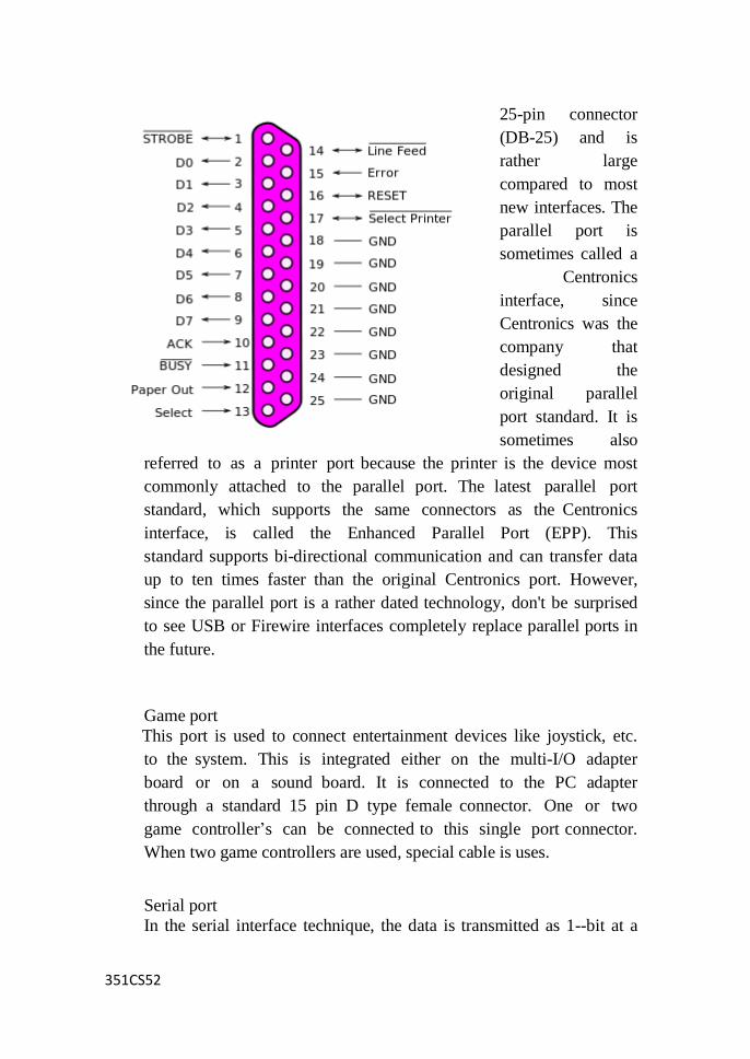
351CS52
25-pin connector
(DB-25) and is
rather large
compared to most
new interfaces. The
parallel port is
sometimes called a
Centronics
interface, since
Centronics was the
company that
designed the
original parallel
port standard. It is
sometimes also
referred to as a printer port because the printer is the device most
commonly attached to the parallel port. The latest parallel port
standard, which supports the same connectors as the Centronics
interface, is called the Enhanced Parallel Port (EPP). This
standard supports bi-directional communication and can transfer data
up to ten times faster than the original Centronics port. However,
since the parallel port is a rather dated technology, don't be surprised
to see USB or Firewire interfaces completely replace parallel ports in
the future.
Game port
This port is used to connect entertainment devices like joystick, etc.
to the system. This is integrated either on the multi-I/O adapter
board or on a sound board. It is connected to the PC adapter
through a standard 15 pin D type female connector. One or two
game controller‘s can be connected to this single port connector.
When two game controllers are used, special cable is uses.
Serial port
In the serial interface technique, the data is transmitted as 1--bit at a

351CS52
time through a single wire. The parallel data (byte) from the
computer bus is converted into serial data (bits) and sent through
the serial cable. It slows down the data transfer rate. It enables to
communicate data transfer over a distance. RS232 is the serial
communication standard. The system normally supports two Serial
ports COM 1 and COM 2. A 9-pin DB9 connector used with COM
1 and 25pin DB 25 connector is used with COM 2 for connecting
devices. An adapted 9 to 25 pin connector can be used to connect
devices either to COM 1 or COM 2. In modern PCs the serial port
interface electronics is included in the motherboard chipset itself.
Serial ports can be enabled by BIOS set-up. The data transfer rate
or the communication speed has to be sent to match the speed of the
devices connected to the system.
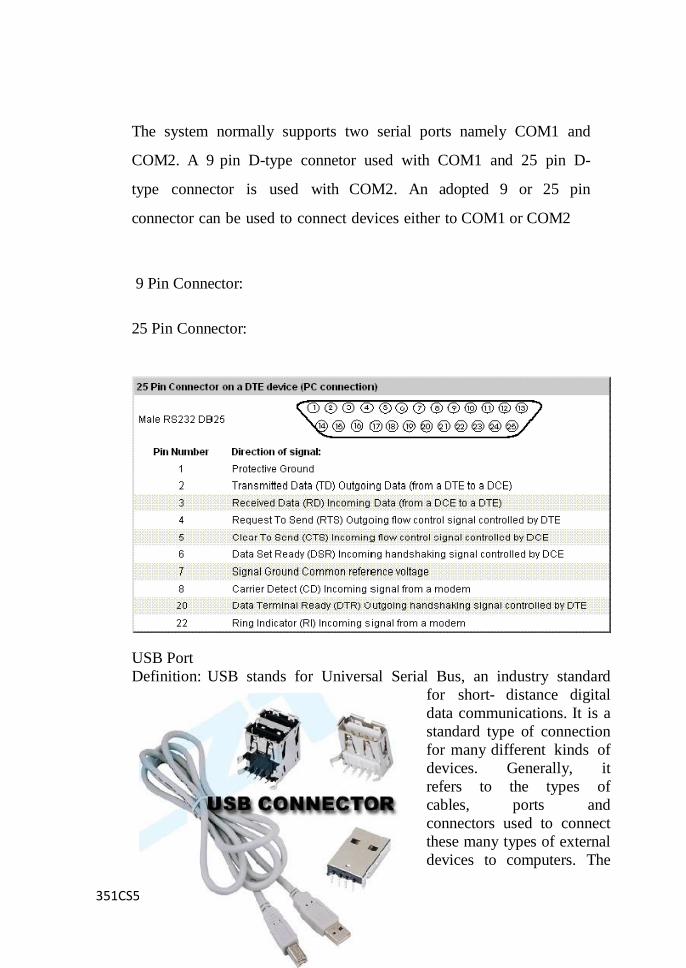
351CS52
The system normally supports two serial ports namely COM1 and
COM2. A 9 pin D-type connetor used with COM1 and 25 pin D-
type connector is used with COM2. An adopted 9 or 25 pin
connector can be used to connect devices either to COM1 or COM2
9 Pin Connector:
25 Pin Connector:
USB Port
Definition: USB stands for Universal Serial Bus, an industry standard
for short- distance digital
data communications. It is a
standard type of connection
for many different kinds of
devices. Generally, it
refers to the types of
cables, ports and
connectors used to connect
these many types of external
devices to computers. The
351CS52
Universal Serial Bus standard is a popular one. USB ports and cables are
used to connect devices such as printers, scanners, flash drives, external
hard drives and more to a computer. In fact, USB has become so
popular, it's even used in nontraditional computer-like devices such as
video game consoles, wireless phones and more. USB allows data to be
transferred between devices. USB ports can also supply electric power
across the cable to
devices without their own power source. Both wired and wireless
versions of the USB standard exist, although only the wired
version involves USB ports and cables. USB also supports Plug-
and-Play installation and hot plugging
Features of USB:
The computer acts as a host.
Upto 127 devices can be connected to the host either directly or by
way of USB hubs.
USB has a data transfer rate of 480 megabits per second.
USB devices are hot swappable - The devices can be
connected and disconnected at any time.
Special type of drives
Special type of drives:
Zip drive
Memory stick
USB-flash drive
IPod Dock version and installation.
Memory Stick:
Memory Stick is a removable flash memory card format, launched by
Sony in October 1998, and is also used in general to describe the
whole family of Memory Sticks. In addition to the original Memory
Stick, this family includes the Memory Stick PRO, a revision that
allows greater maximum storage capacity and faster file transfer
speeds; Memory Stick Duo, a small-form-factor version of the
Memory Stick (including the PRO Duo); and the even smaller
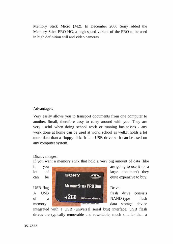
351CS52
Memory Stick Micro (M2). In December 2006 Sony added the
Memory Stick PRO-HG, a high speed variant of the PRO to be used
in high definition still and video cameras.
Advantages:
Very easily allows you to transport documents from one computer to
another. Small, therefore easy to carry around with you. They are
very useful when doing school work or running businesses - any
work done at home can be used at work, school as well.It holds a lot
more data than a floppy disk. It is a USB drive so it can be used on
any computer system.
Disadvantages:
If you want a memory stick that hold a very big amount of data (like
if you are going to use it for a
lot of large document) they
can be quite expensive to buy.
USB flag Drive
A USB flash drive consists
of a NAND-type flash
memory data storage device
integrated with a USB (universal serial bus) interface. USB flash
drives are typically removable and rewritable, much smaller than a
351CS52
floppy disk (1 to 4 inches or 2.5 to 10 cm), and most USB flash
drives weigh less than an ounce (28g). Storage capacities
typically range from 64 MB to 128 GB with steady improvements in
size and price per gigabyte. Some allow 1 million writeor erase
cycles and have 10-year data retention, connected by USB 1.1 or USB
2.0.
USB flash drives offer potential advantages over other portable
storage devices, particularly the floppy disk. They have a more
compact shape, operate faster, hold much more data, have a more
durable design, and operate morereliably due to their lack of moving
parts. Additionally, it has become increasingly common for
computers to be sold without floppy disk drives. USB ports, on the
other hand, appear on almost every current mainstream PC and
laptop. These types of drives use the USB mass storage standard,
supported natively by odern operating systems such as Windows,
Mac OS X, Linux, and other Unix-like systems. USB drives with
USB 2.0 upport can also operate faster than an optical disc drive,
while storing a larger amount of data in a much smallerspace.
Nothing actually moves in a flash drive: the term drive persists
because computers read and write flash-drive data using the same
system commands as for a mechanical disk drive, with the storage
appearing to the computer operating system and user interface as
just another drive.
A flash drive consists of a small printed circuit board protected
inside a plastic, metal, or rubberised case,robust enough for
carrying with no additional protection— in a pocket or on a
key chain, for example. The USB connector is protected by a
removable cap or by retracting into the body of the drive, although
it is not liable to be damaged if exposed. Most flash drives use a
standard type-A USB connection allowing plugging into a port on a
personal computer.
351CS52
Advantages:
Resistance. USB Flash drives are very resistant to scratches and
other kinds of unintentional mechanical damage. They are also
protected against dust penetration. These strong points give them
substantial advantage if compared with their predecessors, such as
compact and floppy disks. This is due to their rigid plastic or metal
case. It makes them ideal for transporting data.
Comfort. It is very convenient to use a USB flash drive on
modern PCs because it fits almost all devices that havea USB port
and the necessary device drivers.
Storage. USB flash drives are extremely compact means of
storage. Some flash drives can store more than a CD (700MB) or even
a DVD (4.7 GB).
Limits:
Damage. No matter how resistant USB flash drives are comparing
with mechanical drives, still they can be damaged or corrupted
by serious physical abuse. The circuitry of a flash drive can be
harmed by improper wiring of the USB port.
Size. USBs flash drives are appreciated for compact size, but at
the same time they can be easily left behind, lost.
Life span. The life span of flash memory devices is measured in
number of write and erase cycles. An average life duration of a
flash drive (under normal conditions) is about several hundred
thousand cycles.
As the device ages the speed of writing process gradually slows.
This is an issue of a special matter in some cases (ex: running
351CS52
application software or an operating system).
Write-protection. Only a few USB flash drives are equipped with
a write- protect mechanism. It usually features a switch on the
driver's housing. This feature makes it possible to use the USB
flash driver for repairing virus- contaminated PCs without infecting
the flash device itself.
In spite of the above limits USB flash drives are the best in their
field. They are constantly used by a wide range of users which
proves their efficiency. What really delights is that nothing is
static, as USB drive are too. Andthe best flash technologies are to
come.
Zip drive:
The Zip drive is a medium-capacity removable disk storage system,
introduced by Iomega in late 1994. Originally, Zip disks had a
capacity of 100 MB, but later versions increased this to first 250
MB and then 750 MB.
The format became the most popular of the super-floppy type
products but was never popular enough to replace the 3.5-inch floppy
disk. Later, rewritable CDs and rewritable DVDs replaced the Zip
drive for mass storage. The Zip brand later covered internal and
external CD writers known as Zip-650 or Zip-CD which had no
relation to the Zip drive.

351CS52
Advantages of ZD:
ZD showed up more responsible and faster then FDD. They never
were on the same market penetration as FDD, as only some new
computers were sold with Zip drives.
Disadvantages of ZD:
Despite of their capacity were not so popular in a market because they
were robust and heavy. The mainly disadvantage is that ZD‘s need
special mechanism in computer (not the same as in FDD!).

351CS52
UNIT – IV
I/O DEVICES AND POWER SUPPLY
Biometric Devices Information:
Biometrics is the science and technology of measuring and analyzing
biological data. In information technology, biometrics refers to
technologies that measure and analyze human body characteristics,
such as fingerprints, eye retinas and irises, voice patterns, facial
patterns and hand measurements, for authentication purposes.
Biometrics devices:
KEYSTROKE PATTERN DEVICES
SIGNATURE DEVICES
VOICE PATTERN DEVICES
HANDPRINT DEVICES
FINGERPRINT DEVICES
RETINA PATTERN DEVICES

351CS52
Iris scanner
Iris scanning technology was first thought of in 1936 by
ophthalmologist Frank Burch. He noticed that each person‘s
iris – the part of the eye that gives color – is unique. It
wasn‘t till 1994 when the algorithm for detecting these
differences was patented by John Daugman of Iridian
Technologies.
Iris scans analyze the features in the colored tissue surrounding
the pupil.
There are many unique points for comparison including
rings, furrows and filaments. The scans use a regular video
camera to capture the iris pattern.
The user looks into the device so that he can see the
reflection of his own eye. The device captures the iris pattern
and compares it to one in a database. Distance varies, but
some models can make positive identification at up to 2 feet.
Verification times vary - generally less than 5 seconds - but
only require a quick glance to activate the identification process.
To prevent a fake eye from being used to fool the system, some
models vary the light levels shone into the eye and watch for
pupil dilation – a fixed pupil means a fake eye.
351CS52
Iris scanners are now in use in various military and criminal
justice facilities but have never gained the wide favor that
fingerprint scanners now enjoy even though the technology is
considered more secure. Devices tend to be bulky in
comparison to fingerprint scanners.
Retinal scanners are similar in operation but require the user
to be very close to a special camera. This camera takes an
image of the patterns created by tiny blood vessels illuminated
by a low intensity laser in the back of the eye – the retina.
Retinal scans are considered impossible to fake and these
scanners can be found in areas needing very high security. High
cost and the need to actually put your eye very close to the
camera prevent them from being used more widely.
How Fingerprint Scanners Work
Biometrics consists of automated methods of recognizing a
person based on unique physical characteristic. Each type of
biometric system, while different in application, contains at
least one similarity: the biometric must be based upon a
distinguishable human attribute such as a person's fingerprint,
iris, voice pattern or even facial pattern.
Today fingerprint devices are by far the most popular form
of biometric security used, with a variety of systems on the
market intended for general and mass market usage. Long
gone are the huge bulky fingerprint scanners; now a
fingerprint scanning device can be small enough to be
incorporated into a laptop for security.
A fingerprint is made up of a pattern of ridges and
furrows as well as characteristics that occur at Minutiae points
(ridge bifurcation or a ridge ending).
Fingerprint scanning essentially provides an identification of a
person based on the acquisition and recognition of those
unique patterns and ridges in a fingerprint.
The actual fingerprint identification process will change
351CS52
slightly between products and systems. The basis of
identification, however, is nearly the same. Standard systems
are comprised of a sensor for scanning a fingerprint and a
processor which stores the fingerprint database and software
which compares and matches the fingerprint to the predefined
database. Within the database, a fingerprint is usually matched
to a reference number, or PIN number which is then matched
to a person's name or account. In instances of security the match
is generally used to allow or disallow access, but today this
can also be used for something as simple as a time clock or
payroll access.
In large government organizations and corporations, biometrics
plays a huge role in employee identification and security.
Additionally some data centers have jumped on the bandwagon
and have implemented biometric scanners to enhances remote
access and management by adding another layer of network
security for system administrators. Unfortunately the cost of
implementing fingerprint and other biometric security
scanning in data centers is still quite expensive, and many
centers still rely on ID badges while waiting until biometric
technology becomes a little more pocket-book friendly.
Today companies have realized that fingerprint scanning is an
effective means of security. While the cost of implementing
biometric scanners in larger organizations and data centers is
still quite costly, we did find several fingerprint scanning
devices which would fit into the budget of many small offices
and home users. These home and small office products are
designed to protect your hard drive, notebook or even to
remove the need for users to remember multiple passwords.
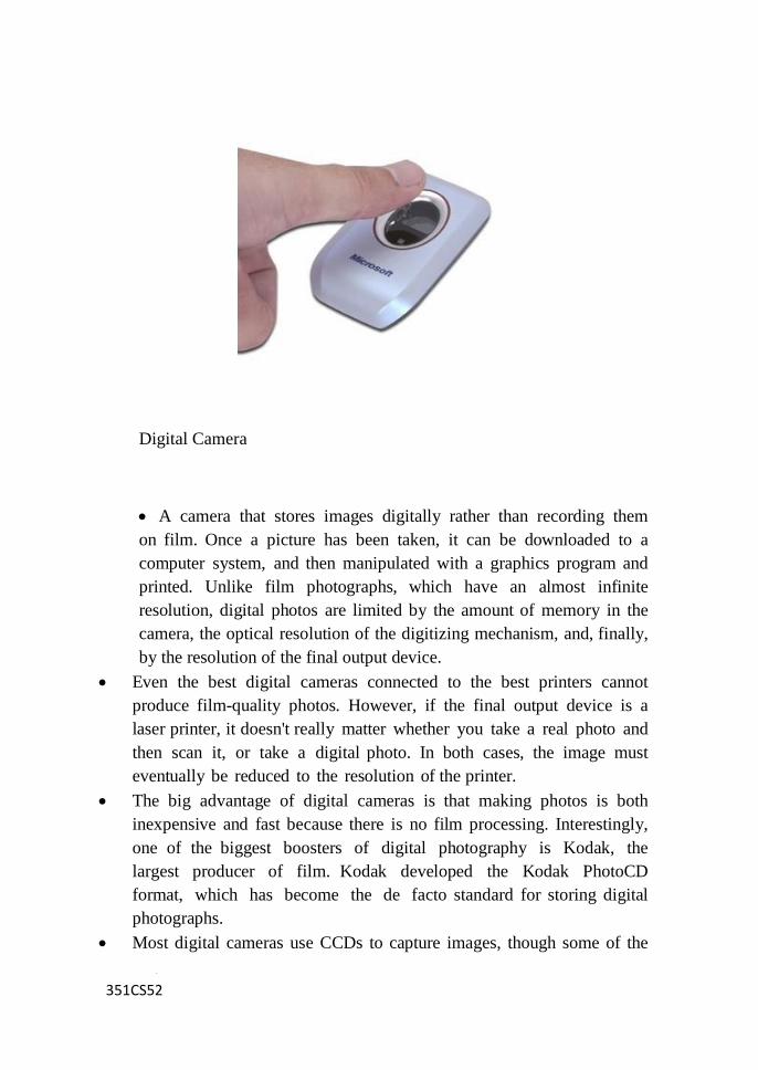
351CS52
Digital Camera
A camera that stores images digitally rather than recording them
on film. Once a picture has been taken, it can be downloaded to a
computer system, and then manipulated with a graphics program and
printed. Unlike film photographs, which have an almost infinite
resolution, digital photos are limited by the amount of memory in the
camera, the optical resolution of the digitizing mechanism, and, finally,
by the resolution of the final output device.
Even the best digital cameras connected to the best printers cannot
produce film-quality photos. However, if the final output device is a
laser printer, it doesn't really matter whether you take a real photo and
then scan it, or take a digital photo. In both cases, the image must
eventually be reduced to the resolution of the printer.
The big advantage of digital cameras is that making photos is both
inexpensive and fast because there is no film processing. Interestingly,
one of the biggest boosters of digital photography is Kodak, the
largest producer of film. Kodak developed the Kodak PhotoCD
format, which has become the de facto standard for storing digital
photographs.
Most digital cameras use CCDs to capture images, though some of the
351CS52
newer less expensive cameras use CMOS chips instead.
Working Principle In principal, a digital camera is similar to a traditional film-based camera.
There's a viewfinder to aim it, a lens to focus the image onto a
light-sensitive device, some means by which several images can be
stored and removed for later use, and the whole lot is fitted into a box.
In a conventional camera, light-sensitive film captures images and is
used to store them after chemical development. Digital photography
uses a combination of advanced image sensor technology and memory
storage, which allows images to be captured in a digital format that
is available instantly - with no need for a "development" process.
Although the principle may be the same as a film camera, the inner
workings of a digital camera are quite different, the imaging being
performed either by a charge coupled device (CCD) or CMOS
(complementary metal-oxide semiconductor) sensors. Each sensor
element converts light into a voltage proportional to the brightness
which is passed into an analogue-to-digital converter (ADC) which
translates the variations of the CCD into discrete binary code.
The digital output of the ADC is sent to a digital signal processor
(DSP) which adjusts contrast and detail, and compresses the image
before sending it to the storage medium. The brighter the light, the
higher the voltage and the brighter the resulting computer pixel. The
more elements, the higher the resolution, and the greater the detail that
can be captured.
This entire process is very environment-friendly. The CCD or CMOS
sensors are fixed in place and it can go on taking photos for the
lifetime of the camera. There's no need to wind film between two
spools either, which helps minimize the number of moving parts.
Features of a Digital Camera: Resolution
This term refers to the sharpness, or detail, of a picture. The higher
the number of pixels, the higher the resolutions. You can determined
the resolution you need by determining what you really want to do
with these pictures. Picture size is measured by how many pixels
make up an image and is measured by horizontal by vertical
resolution, as in 1280 x 960. The manufacturers break this down to

351CS52
about 5 main different categories of resolutions, expressed in mega
pixels.
* 1 megapixel cameras - These are nearly obsolete. They
are good for posting images to the Internet, looking at images on a
monitor, and emailing photos. Cell phones and camcorders tend to have
around 1 megapixel capability.
* 2 megapixel cameras - The maximum resolution here is
1600 x 1200, which is better than the resolution of most computer
monitors. Also good for posting pictures to the Internet, viewing
images on a monitor, and emailing. It can also print images up to
8x10 inches, and will allow you to do basic graphics work.
* 3-5 megapixel cameras - A 3 megapixel camera will print
up to 11x14 inch images. If you are not a professional, this is probably
as detailed as you need to get. It does everything a 2 does, plus allows
you to do professional graphics work. The cost of a 3 megapixel
camera is much more reasonable than that of a 4 or 5, but still allows
you to have great flexibility in use. 4 and 5 mexapixel cameras will
have even larger images and print sizes.
Memory Digital cameras store pictures as data files rather than on film.
The size of your memory determines the number of pictures you can
take before downloading the images to a computer, at which time you
can go back and fill the memory up with new pictures. Most cameras
come with only 8 mega bytes (MB) of memory, which for a 2 or 3
mega pixel camera could be only 10 to 40 photos. More memory is
available by buying removable memory, such as a memory card.
Flash Type
A flash, of course, is the extra light needed to shoot inside or in low-
light conditions. Most digital cameras have built-in flash with a range
of 10 to 16 feet. Other flash options include:
351CS52
Red Eye Reduction - Two flashes are emitted, the first to contract the
iris so that the eye doesn't reflect as much light with the second,
which keeps friends and family member from looking fiendish in the
photo.
External Flash - More powerful than automatic, this allows you to
attach the flash to the camera and place it strategically. The types
include "flash sync" and "Hot Shoe." Cameras that include external
options will generally have automatic flash as well.
Burst Mode - Known also as Rapid Fire and Continuous Shooting
mode. In general, there is a 1-2 second time lag between pressing the
shutter button and a picture being taken with a digital camera. Then
there is a 2-30 second recovery time before the camera is able to take
another photo. With the Burst Mode feature you can take several
pictures in a row. This useful for taking shots in motion, such as
children playing or sports events.
Optical Zoom-There are 2 types of zoom lenses, digital and optical.
Digital zoom simply enlarges the picture without adding any clarity of
detail. The same thing can be done with editing and cropping software.
Optical zoom will do what you really want; add detail and sharpness.
Compression - This process shrinks the file size of a photo.
Uncompressed photos are clearer, the files are enormous and require
huge amounts of memory. JPEG format compresses the files, allowing
you to store more, save, download, and email photos at a faster rate. For
general use, JPEG is fine.
Power Source - Digital cameras are voracious eaters of batteries. They
use either a rechargeable battery pack or traditional batteries, usually
2 - 4 double A. Some have an AC adapter as well. For rechargeable
batteries, which you want unless you really like to buy a lot of batteries,
and often, NIMH batteries can be charged up to 1000 times, while
351CS52
Lithium Ion batteries can also be charged up to 1000 times and last
twice as long as NIMHs.
Lens - Lens length will determine how much of a scene will fit into a
picture. Some cameras have fixed focus lenses, which are preset to focus
at a certain range. These pictures typically focus between a wide angle
lens and normal range. Many cameras have auto focus, which pick an
item in the center of the viewfinder around which to focus. To get an
idea of a camera's range, it will be listed as the 35mm equivalent.
Focus and Exposure - Most cameras have auto focus, but higher end
cameras will include a manual focus capability. Panorama picture
taking is available, as well as various types of light sensitivity. For
instance, a camera rated at ISO 100 has approximately the same
light setting as a normal camera using ISO 100 film. The higher the
ISO setting, determined by the aperture, the less light a camera needs to
take a good image.
I/O Devices Definition:
I/O is an abbreviation of Input / Output and refers to the transfer of data
to or from an application. Input devices are usually but not always
character input devices such as the keyboard, mouse or keyboard.
They can also include stream devices like a disk. Output devices
include the screen or a printer or anything plugged into a PC's port.
Some devices can only send or receive - try sending data to a mouse!
If the device can do both input and output (say another PC attached to a
serial or parallel cable), it is termed bidirectional.
Modem Definition:
Modem Short for modulator-demodulator. A modem is a device
or program that enables a computer to transmit data over, for
example, telephone or cable lines. Computer information is stored
351CS52
digitally, whereas information transmitted over telephone lines is
transmitted in the form of analog waves. A modem converts
between these two forms.
Fortunately, there is one standard interface for connecting external
modems to computers called RS-232. Consequently, any external
modem can be attached to any computer that has an RS-232 port,
which almost all personal computers have. There are also modems
that come as an expansion board that you can insert into a vacant
expansion slot. These are sometimes called onboard or internal
modems.
While the modem interfaces are standardized, a number of
different protocols for formatting data to be transmitted over
telephone lines exist. Some, like CCITT V.34, are official
standards, while others have been developed by private
companies. Most modems have built-in support for the more
common protocols -- at slow data transmission speeds at least,
most modems can communicate with each other. At high
transmission speeds, however, the protocols are less standardized.
Aside from the transmission protocols that they support, the
following characteristics distinguish one modem from another:
bps : How fast the modem can transmit and receive data. At
slow rates, modems are measured in terms of baud rates. The
slowest rate is 300 baud (about 25 cps). At higher speeds, modems
are measured in terms of bits per second (bps). The fastest modems
run at 57,600 bps, although they can achieve even higher data
transfer rates by compressing the data. Obviously, the faster the
transmission rate, the faster you can send and receive data. Note,
however, that you cannot receive data any faster than it is being
sent. If, for example, the device sending data to your computer is
sending it at 2,400 bps, you must receive it at 2,400 bps. It does
not always pay, therefore, to have a very fast modem. In
addition, some telephone lines are unable to transmit data reliably
at very high rates.
voice/data: Many modems support a switch to change between
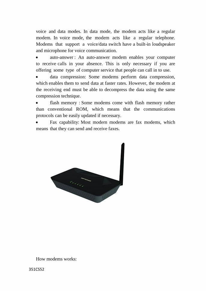
351CS52
voice and data modes. In data mode, the modem acts like a regular
modem. In voice mode, the modem acts like a regular telephone.
Modems that support a voice/data switch have a built-in loudspeaker
and microphone for voice communication.
auto-answer : An auto-answer modem enables your computer
to receive calls in your absence. This is only necessary if you are
offering some type of computer service that people can call in to use.
data compression: Some modems perform data compression,
which enables them to send data at faster rates. However, the modem at
the receiving end must be able to decompress the data using the same
compression technique.
flash memory : Some modems come with flash memory rather
than conventional ROM, which means that the communications
protocols can be easily updated if necessary.
Fax capability: Most modern modems are fax modems, which
means that they can send and receive faxes.
How modems works:
351CS52
When a modem first makes a connection, you will hear
screeching sounds coming from the modem. These are digital signals
coming from the computer to which you are connecting being
modulated into audible sounds. The modem sends a higher-pitched
tone to represent the digit 1 and a lower-pitched tone to represent the
digit 0.
At the other end of your modem connection, the computer
attached to its modem reverses this process. The receiving modem
demodulates the various tones into digital signals and sends them to
the receiving computer. Actually, the process is a bit more
complicated than sending and receiving signals in one direction and
then another. Modems simultaneously send and receive signals in
small chunks. The modems can tell incoming from outgoing data
signals by the type of standard tones they use.
Another part of the translation process involves transmission
integrity. The modems exchange an added mathematical code along the
way. This special code, called a checksum, lets both computers know
if the data segments are coming through properly. If the
mathematical sums do not match, the modems communicate with
each other by resending the missing segments of data. Modems also
have special circuitry that allows them to compress digital signals
before modulating them and then decompressing them after
demodulating the signals. The compression/decompression process
compacts the data so that it can travel along telephone lines more
efficiently.
Modems convert analog data transmitted over phone lines into
digital data, which computers can read. They also convert digital data
into analog data so that it can be transmitted. This process involves
modulating and demodulating the computer's digital signals into
analog signals that travel over the telephone lines. In other words, the
modem translates computer data into the language used by telephones
and then reverses the process to translate the responding data back
into computer language.

351CS52
Signal conversion performed by modems. A modem converts a digital
signal to an analog tone (modulation) and reconverts the analog tone
into its original digital signal (demodulation).
How to Install an External Modem
Installing an external modem is easy and takes little time. You don't
have to open the computer or install modem cards. This procedure
applies to PC and Macintosh computers.
Step 1
Unpack the modem and its accessories. You should have the modem,
cable, phone cord, power adapter, installation diskette or CD, and
instruction manual.
Step 2
Turn off the computer and any attached devices.
Step 3
Attach one end of the modem cable to the serial port (wide, 25-pin
connector) on the computer and the other end to the modem. The serial
port on the Macintosh is a small, round port marked with a telephone
icon.
Step 4
Connect one end of the phone cord to the modem port marked "wall" or
351CS52
"line" and the other end to the wall jack of your phone line. If the modem
will be sharing the line with a telephone, connect the cord of the
telephone to the modem port marked "phone."
Step 5
Attach the power adapter plug to the modem and the power transformer
plug to the power outlet, if this is required for your modem.
Step 6
Turn on the computer and the modem, if it has an on/off switch.
Step 7
When your computer starts up, follow the software installation
instructions if prompted by your computer system (e.g., Windows Plug 'n
Play feature).
Step 8
Insert the installation diskette or CD (if you do not receive prompts for
installing the modem), click the drive, and click (or double-click) the
installation program on the diskette or CD.
Step 9
Run any test program that comes with the installation software to ensure
that the modem is working correctly.
Tips & Warnings
Check the light indicators on the modem that show that it is
working. If the light indicators are not on or flashing, check all
hardware connections.
If you do not have an available serial port and do not want to
replace your external modem with an internal modem, consider
installing a serial card.
Internal computer modems. Some computers have an internal
351CS52
modem which can be a built-in modem or a PC card modem.
Check the modem specifications to determine whether the
modem requires an analog phone line (used in most homes) or
a digital phone line (used in most offices). Using the wrong
phone line can damage your modem.
A router is a device in computer networking that forwards data packets to
their destinations, based on their addresses. The work a router does it
called routing, which is somewhat like switching, but a router is different
from a switch. The latter is simply a device to connect machines to form a
LAN.
How a Router Works
When data packets are transmitted over a network (say the
Internet), they move through many routers (because they pass
through many networks) in their journey from the source machine
to the destination machine. Routers work with IP packets, meaning
that it works at the level of the IP protocol.
Each router keeps information about its neighbors (other
routers in the same or other networks). This information includes
the IP address and the cost, which is in terms of time, delay and
other network considerations. This information is kept in a routing
table, found in all routers.
When a packet of data arrives at a router, its header
information is scrutinized by the router. Based on the destination
and source IP addresses of the packet, the router decides which
neighbor it will forward it to. It chooses the route with the least cost,
and forwards the packet to the first router on that route.
Routers perform the following functions:

351CS52
Restrict network broadcasts to the local LAN
Act as the default gateway.
Move data between networks
Learn and advertise loop free paths between sub-networks.
Types of Modem
The modems are classified into two types. They are
1. Internal modem
2. External Modem
1. Internal Modem
Internal modems are built into the motherboard or a circuit
board that plugs into an expansion slot inside a computer.
Internal modems are also known as analog or dial-up
modems. Modern analog modems transfer information at
about 56 kilobits per second (56K) over a telephone line.
• Analog dial-up modems are susceptible to phone-line
noise or interference from electrical devices and slower
internet connection speeds. However, 56K dial- up modems
can be used anywhere a phone line is available.
2. External Modem:
The modem which is placed outside the computer is called
External Modem.
External modems are portable devices that you can attach to
a serial or USB (Universal Serial Bus) port on your
computer.
External modems can be disconnected from your computer
and used with other computers.
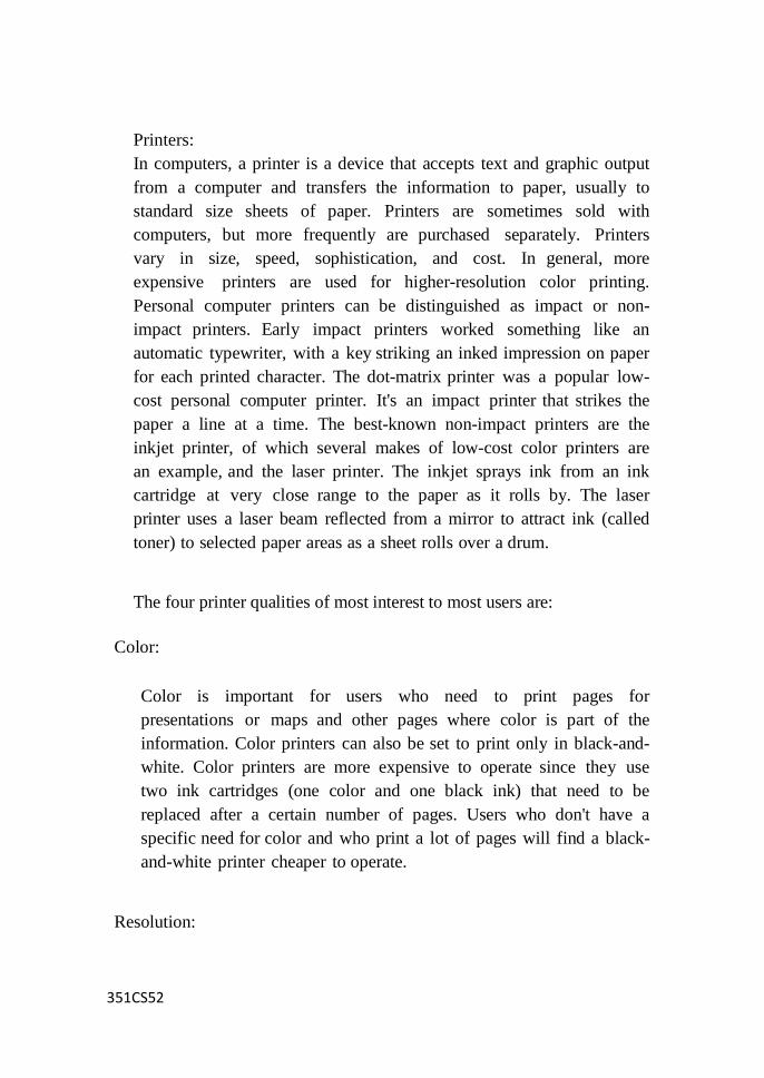
351CS52
Printers:
In computers, a printer is a device that accepts text and graphic output
from a computer and transfers the information to paper, usually to
standard size sheets of paper. Printers are sometimes sold with
computers, but more frequently are purchased separately. Printers
vary in size, speed, sophistication, and cost. In general, more
expensive printers are used for higher-resolution color printing.
Personal computer printers can be distinguished as impact or non-
impact printers. Early impact printers worked something like an
automatic typewriter, with a key striking an inked impression on paper
for each printed character. The dot-matrix printer was a popular low-
cost personal computer printer. It's an impact printer that strikes the
paper a line at a time. The best-known non-impact printers are the
inkjet printer, of which several makes of low-cost color printers are
an example, and the laser printer. The inkjet sprays ink from an ink
cartridge at very close range to the paper as it rolls by. The laser
printer uses a laser beam reflected from a mirror to attract ink (called
toner) to selected paper areas as a sheet rolls over a drum.
The four printer qualities of most interest to most users are:
Color:
Color is important for users who need to print pages for
presentations or maps and other pages where color is part of the
information. Color printers can also be set to print only in black-and-
white. Color printers are more expensive to operate since they use
two ink cartridges (one color and one black ink) that need to be
replaced after a certain number of pages. Users who don't have a
specific need for color and who print a lot of pages will find a black-
and-white printer cheaper to operate.
Resolution:

351CS52
Printer resolution (the sharpness of text and images on paper) is
usually measured in dots per inch (dpi). Most inexpensive printers
provide sufficient resolution for most purposes at 600 dpi.
Speed:
If you do much printing, the speed of the printer becomes important.
Inexpensive printers print only about 3 to 6 sheets per minute. Color
printing is slower. More expensive printers are much faster.
Memory:
Most printers come with a small amount of memory (for example,
one megabyte) that can be expanded by the user. Having more than
the minimum amount of memory is helpful and faster when printing
out pages with large images or tables with lines around them (which
the printer treats as a large image).
Dot-matrix printer
An impact printer that produces text and graphics when tiny wire pins
on the print head strike the ink ribbon. The print head runs back and
forth on the paper like a typewriter. When the ink ribbon presses on
the paper, it creates dots that form text and images. Higher number of
pins means that the printer prints more dots per character, thus
resulting in higher print quality.
Dot-matrix printers were very popular and the most common type of
printer for personal computer in 70‘s to 80‘s. However, their use was
gradually replaced by inkjet printers in 90‘s. As of today, dot matrix
printers are only used in some point-of-sales terminals, or businesses
where printing of carbon copy multi-part forms or data logging are
needed.
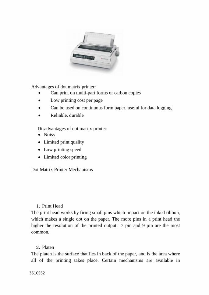
351CS52
Advantages of dot matrix printer:
Can print on multi-part forms or carbon copies
Low printing cost per page
Can be used on continuous form paper, useful for data logging
Reliable, durable
Disadvantages of dot matrix printer:
Noisy
Limited print quality
Low printing speed
Limited color printing
Dot Matrix Printer Mechanisms
1. Print Head
The print head works by firing small pins which impact on the inked ribbon,
which makes a single dot on the paper. The more pins in a print head the
higher the resolution of the printed output. 7 pin and 9 pin are the most
common.
2. Platen
The platen is the surface that lies in back of the paper, and is the area where
all of the printing takes place. Certain mechanisms are available in
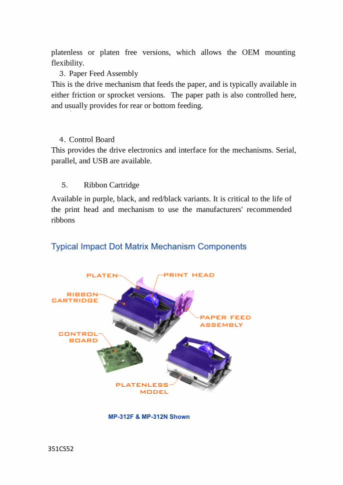
351CS52
platenless or platen free versions, which allows the OEM mounting
flexibility.
3. Paper Feed Assembly
This is the drive mechanism that feeds the paper, and is typically available in
either friction or sprocket versions. The paper path is also controlled here,
and usually provides for rear or bottom feeding.
4. Control Board
This provides the drive electronics and interface for the mechanisms. Serial,
parallel, and USB are available.
5. Ribbon Cartridge
Available in purple, black, and red/black variants. It is critical to the life of
the print head and mechanism to use the manufacturers' recommended
ribbons

351CS52
Impact Dot Matrix Printer Mechanism Components
Printhead technologies used today:
If the CPU is the heart of a computer, then the printhead is the engine
of a dot matrix printer. Any matrix printhead uses electro-magnetic
field to fire the print head wires. There are two main printhead
engineering technologies - in the first one electro-magnetic field shoots
the print head's wire. In the second one, the so called permanent
magnet printheads, a spring shoots the printhead wire and the
magnetic field just holds the spring in stressed and ready to shoot
printhead wire position. When the electro-magnetic field equalizes the
magnetic field, the spring is released to shoot the wire. To see all
this in action, take a look at the picture bellow.
Classical printhead mechanism is showed from the left side. The
permanent magnet print head mechanism you may see at right.
How the serial dot matrix printers work?
As the printer head moves in horizontal direction, the printhead
controller sends electrical signals which forces the appropriate wires to
strike against the inked ribbon, making dots on the paper and forming
the desired characters. The most commonly used printer heads has 9 print
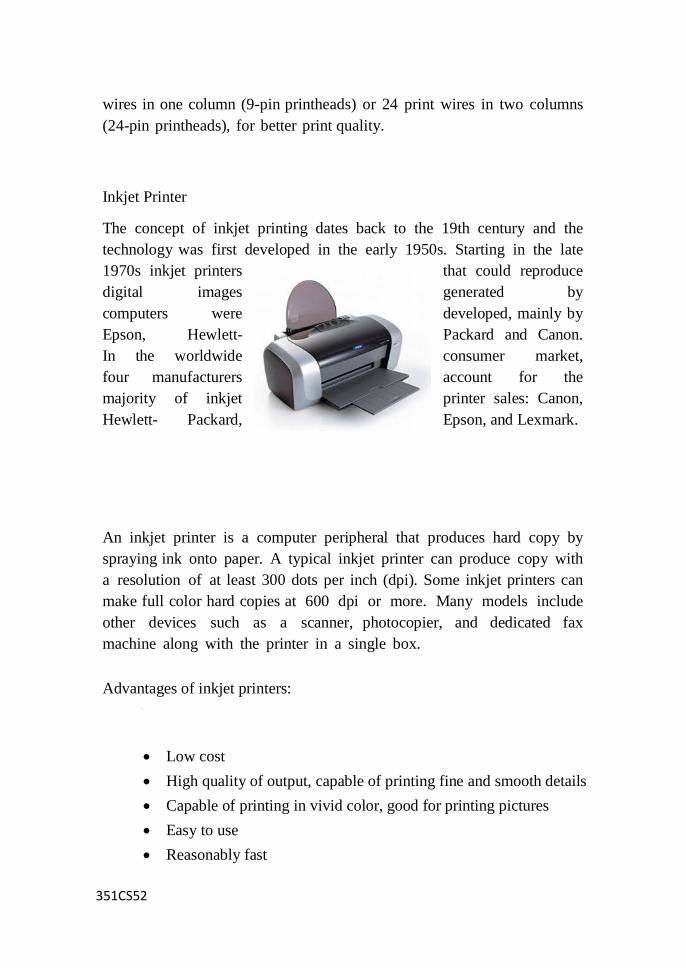
351CS52
wires in one column (9-pin printheads) or 24 print wires in two columns
(24-pin printheads), for better print quality.
Inkjet Printer
The concept of inkjet printing dates back to the 19th century and the
technology was first developed in the early 1950s. Starting in the late
1970s inkjet printers that could reproduce
digital images generated by
computers were developed, mainly by
Epson, Hewlett- Packard and Canon.
In the worldwide consumer market,
four manufacturers account for the
majority of inkjet printer sales: Canon,
Hewlett- Packard, Epson, and Lexmark.
An inkjet printer is a computer peripheral that produces hard copy by
spraying ink onto paper. A typical inkjet printer can produce copy with
a resolution of at least 300 dots per inch (dpi). Some inkjet printers can
make full color hard copies at 600 dpi or more. Many models include
other devices such as a scanner, photocopier, and dedicated fax
machine along with the printer in a single box.
Advantages of inkjet printers:
Low cost
High quality of output, capable of printing fine and smooth details
Capable of printing in vivid color, good for printing pictures
Easy to use
Reasonably fast
351CS52
Quieter than dot matrix printer
No warm up time
Disadvantages of inkjet printers:
Print head is less durable, prone to clogging and damage
Expensive replacement ink cartridges
Not good for high volume printing
Printing speed is not as fast as laser printers
Ink bleeding, ink carried sideways causing blurred effects on some
papers
Aqueous ink is sensitive to water, even a small drop of
water can cause blurring
Cannot use highlighter marker on inkjet printouts
Thermal Technology
Most inkjets use thermal technology, whereby heat is used to fire ink
onto the paper. There are three main stages with this method. The
squirt is initiated by heating the ink to create a bubble until the pressure
forces it to burst and hit the paper. The bubble then collapses as the
element cools, and the resulting vacuum draws ink from the reservoir to
replace the ink that was ejected. This is the method favored by Canon and
Hewlett-Packard.
Thermal technology imposes certain limitations on the printing process in
that whatever type of ink is used, it must be resistant to heat because the
firing process is heat-based. The use of heat in thermal printers creates
a need for a cooling process as well, which levies a small time overhead
on the printing process.
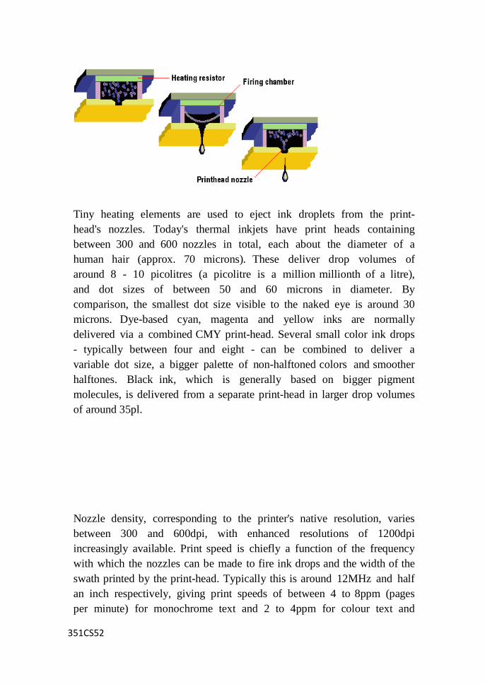
351CS52
Tiny heating elements are used to eject ink droplets from the print-
head's nozzles. Today's thermal inkjets have print heads containing
between 300 and 600 nozzles in total, each about the diameter of a
human hair (approx. 70 microns). These deliver drop volumes of
around 8 - 10 picolitres (a picolitre is a million millionth of a litre),
and dot sizes of between 50 and 60 microns in diameter. By
comparison, the smallest dot size visible to the naked eye is around 30
microns. Dye-based cyan, magenta and yellow inks are normally
delivered via a combined CMY print-head. Several small color ink drops
- typically between four and eight - can be combined to deliver a
variable dot size, a bigger palette of non-halftoned colors and smoother
halftones. Black ink, which is generally based on bigger pigment
molecules, is delivered from a separate print-head in larger drop volumes
of around 35pl.
Nozzle density, corresponding to the printer's native resolution, varies
between 300 and 600dpi, with enhanced resolutions of 1200dpi
increasingly available. Print speed is chiefly a function of the frequency
with which the nozzles can be made to fire ink drops and the width of the
swath printed by the print-head. Typically this is around 12MHz and half
an inch respectively, giving print speeds of between 4 to 8ppm (pages
per minute) for monochrome text and 2 to 4ppm for colour text and
351CS52
graphics.
Inkjet Ink
Whatever technology is applied to printer hardware, the final product
consists of ink on media, so these two elements are vitally important when
it comes to producing quality results. The quality of output from inkjet
printers ranges from poor, with dull colors and visible banding, to
excellent, near-photographic quality.
Two entirely different types of ink are used in inkjet printers: one is
slow and penetrating and takes about ten seconds to dry, and the other
is fast-drying ink which dries about 100 times faster. The former is
generally better suited to straightforward monochrome printing, while the
latter is typically used for color printing. Because different inks are
mixed to create colors, they need to dry as quickly as possible to avoid
blurring. If slow-drying ink is used for color printing, the colors tend to
bleed into one another before they‘ve dried.
The ink used in inkjet technology is water-based, and this caused the
results from some of the earlier printer models to be prone to smudging
and running. Oil- based ink is not really a solution for this problem
because it would impose a far higher maintenance cost on the hardware.
Printer manufacturers are making continual progress in the development of
water-resistant inks, but the output from inkjet printers is still generally
poorer than from laser printing.
One of the major goals of inkjet manufacturers is to develop the ability to
print on almost any media. The secret to this is ink chemistry, and most
inkjet manufacturers will jealously protect their own formulas.
Companies like Hewlett- Packard, Canon and Epson invest large sums of
money in research to make continual advancements in ink pigments,
qualities of light fastness and water fastness, and suitability for printing
on a wide variety of media.
Today's inkjets use dyes, based on small molecules (<50 nm), for the
351CS52
cyan, magenta and yellow inks. These have high brilliance and wide color
gamut, but are neither light- or water-fast enough. Pigments, based on
larger (50 to 100 nm) molecules, are more waterproof and fade-resistant,
but they aren't transparent and cannot yet deliver the range of colors
available from dye-based inks. This means that pigments are currently
only used for the black ink. Future developments will likely concentrate
on creating water-fast and light-fast CMY inks based on smaller pigment-
type molecules.
Operation
Inkjet printing, like laser printing, is a non-impact process. Ink is
emitted from nozzles while they pass over media. The operation of an
inkjet printer is easy to visualize: liquid ink in various colors being
squirted onto paper and other media, like plastic film and canvas, to
build an image.
A print head scans the page in horizontal strips, using the printer's
motor assembly to move it from left to right and back again, while the
paper is rolled up in vertical steps, again by the printer. A strip (or row)
of the image is printed, then the paper moves on, ready for the next
strip.
To speed things up, the print head doesn‘t print just a single row of
pixels in each pass, but a vertical row of pixels at a time.
For most inkjet printers, the print head takes about half a second to
print the strip across a page. On a typical 8 1/2"-wide page, the print
head operating at 300 dpi deposits at least 2,475 dots across the page.
This translates into an average response time of about 1/5000th of a
second. Quite a technological feat! In the future, however, advances
will allow for larger print heads with more nozzles firing at faster
frequencies, delivering native resolutions of up to 1200dpi and print
speeds approaching those of current color laser printers (3 to 4 pages
per minute in color, 12 to 14ppm in monochrome).
In other words, declining costs for improving technology.
There are several types of inkjet printing. The most common is
"drop on demand" (DOD), which means squirting small droplets of
ink onto paper through tiny nozzles; like turning a water hose on
and off 5,000 times a second. The amount of ink propelled onto
the page is determined by the print driver software that dictates which
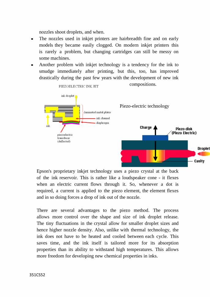
351CS52
nozzles shoot droplets, and when.
The nozzles used in inkjet printers are hairbreadth fine and on early
models they became easily clogged. On modern inkjet printers this
is rarely a problem, but changing cartridges can still be messy on
some machines.
Another problem with inkjet technology is a tendency for the ink to
smudge immediately after printing, but this, too, has improved
drastically during the past few years with the development of new ink
compositions.
Piezo-electric technology
Epson's proprietary inkjet technology uses a piezo crystal at the back
of the ink reservoir. This is rather like a loudspeaker cone - it flexes
when an electric current flows through it. So, whenever a dot is
required, a current is applied to the piezo element, the element flexes
and in so doing forces a drop of ink out of the nozzle.
There are several advantages to the piezo method. The process
allows more control over the shape and size of ink droplet release.
The tiny fluctuations in the crystal allow for smaller droplet sizes and
hence higher nozzle density. Also, unlike with thermal technology, the
ink does not have to be heated and cooled between each cycle. This
saves time, and the ink itself is tailored more for its absorption
properties than its ability to withstand high temperatures. This allows
more freedom for developing new chemical properties in inks.

351CS52
Epson's latest mainstream inkjets have black print-heads with 128
nozzles and colour (CMY) print-heads with 192 nozzles (64 for each
color), addressing a native resolution of 720 by 720dpi. Because the
piezo process can deliver small and perfectly formed dots with
high accuracy, Epson is able to offer an enhanced resolution of
1440 by 720dpi - although this is achieved by the print-head making
two passes, with a consequent reduction in print speed. The tailored
inks Epson has developed for use with its piezo technology are
solvent-based and extremely quick-drying. They penetrate the paper
and maintain their shape rather than spreading out on the surface and
causing dots to interact with one another. The result is extremely good
print quality, especially on coated or glossy paper.
The laser printer was introduced by Hewlett-Packard in 1984, based on
technology developed by Canon. It worked in a similar way to a
photocopier, the difference being the light source. With a
photocopier a page is scanned with a bright light, while with a laser
printer the light source is, not surprisingly, a laser. After that the
process is much the same, with the light creating an electrostatic
image of the page onto a charged photoreceptor, which in turn attracts
toner in the shape of an electrostatic charge.
Laser printers quickly became popular due to the high quality of their
print and their relatively low running costs. As the market for lasers
has developed, competition between manufacturers has become
increasingly fierce, especially in the production of budget models.
Prices have gone down and down as manufacturers have found new
ways of cutting costs. Output quality has improved, with 600dpi
resolution becoming more standard, and build has become smaller,
making them more suited to home use.
Advantages of laser printers:
High resolution
High print speed
No smearing
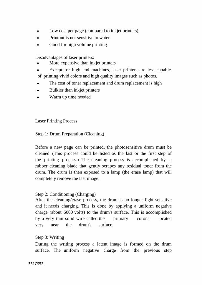
351CS52
Low cost per page (compared to inkjet printers)
Printout is not sensitive to water
Good for high volume printing
Disadvantages of laser printers:
More expensive than inkjet printers
Except for high end machines, laser printers are less capable
of printing vivid colors and high quality images such as photos.
The cost of toner replacement and drum replacement is high
Bulkier than inkjet printers
Warm up time needed
Laser Printing Process
Step 1: Drum Preparation (Cleaning)
Before a new page can be printed, the photosensitive drum must be
cleaned. (This process could be listed as the last or the first step of
the printing process.) The cleaning process is accomplished by a
rubber cleaning blade that gently scrapes any residual toner from the
drum. The drum is then exposed to a lamp (the erase lamp) that will
completely remove the last image.
Step 2: Conditioning (Charging)
After the cleaning/erase process, the drum is no longer light sensitive
and it needs charging. This is done by applying a uniform negative
charge (about 6000 volts) to the drum's surface. This is accomplished
by a very thin solid wire called the primary corona located
very near the drum's surface.
Step 3: Writing
During the writing process a latent image is formed on the drum
surface. The uniform negative charge from the previous step
351CS52
becomes discharged at precise points where the image is produced.
The actual writing is done with the laser. Where the laser strikes the
drum will now become less-negatively charged.
Step 4: Developing
After the writing process the image is no more than an invisible
array of electrostatic charges on the drum's surface. The toner is used
to develop it. When the toner is ready to be applied, it is exposed to
a cylinder (developer roller) that contains a permanent magnet. It is
here that the toner receives a strong negative charge. The areas of
low charge on the drum now attract the toner from the cylinder.
This will fill-in the electromagnetic image. The other areas repel
the equally negatively charged toner. The drum now holds an image
that is ready to be transferred to the paper.
Step 5 : Transfer
At this point, the developed image is transferred to the paper. The
paper is exposed to the transfer corona which fixes a powerful
positive charge to the paper that allows it to pry the negatively charged
toner particles from the drum.
Step 6 : Fusing
After the transfer process, the toner image is only laying on the
surface of the paper, held by a small charge. It must be permanently
bonded to the paper before it can be touched. The fuser assembly,
along with the pressure roller, melts and presses the image into the
paper's surface.
Components of a Laser Printer
A laser printer is a combination of mechanical and electronic
components. Although the internal workings of the printer
generally are not a concern of the average PC technician, you
should be familiar with the parts and processes involved in their

351CS52
operation.
Paper Transport:
The paper path for laser printers ranges from a simple, straight
path to the complicated turns of devices with options such as
duplexers, mailboxes, and finishing tools like collators and staplers.
The goal is the same for all these devices- to move the paper from a
supply bin to the engine where the image is laid on the paper and
fixed to it, and then to a hopper for delivery to the user. Most
printers handle a set range of paper stocks and sizes in the normal
paper path, and a more extensive range (usually heavier paper or
labels) that can be sent though a second manual feed, one sheet at a
time. When users fail to follow the guidelines for the allowed
stocks, paper jams often result.
Logic Circuits:
Laser printers usually have a motherboard much like that of a PC,
complete with CPU, memory, BIOS, and ROM modules
containing printer languages and fonts. Advanced models often
employ a hard disk drive and its controller, a network adapter, a SCSI
host adapter, and secondary cards for finishing options. When
upgrading a printer, check for any updates to the BIOS, additional
memory requirements for new options, and firmware revisions.
User Interface:
The basic laser printer often offers little more than a "power on"
LED and a second light to indicate an error condition. Advanced
models have LED panels with menus, control buttons, and an array of
status LEDs.
Toner and Toner Cartridges:
To reduce maintenance costs, laser printers use disposable
cartridges and other parts that need periodic replacement. The
primary consumable is toner, a very fine plastic powder bonded to
iron particles. The printer cartridge also holds the toner cylinder, and
351CS52
often the photosensitive drum. The cartridge requires replacement
when the level of toner is too low to produce a uniform, dark
print. Some "starter" cartridges shipped with a new printer print
only 750 sheets or so, while high-capacity units can generate 12,000
or more pages.
Photosensitive Drum:
The photosensitive drum is a key component and usually is a part of
the toner cartridge. The drum is an aluminum cylinder that is coated
with a photosensitive compound and electrically charged. It captures
the image to be printed on the page and also attracts the toner which is
to be placed on the page.
IMPORTANT The drum should not be exposed to any more light
than is absolutely necessary. Such exposure will shorten its useful life.
The surface must also be kept free of fingerprints, dust, and
scratches. If these are present, they will cause imperfections on
any prints made with the drum. The best way to ensure a clean
drum is to install it quickly and carefully and leave it in place
until it must be replaced.
Laser:
The laser beam paints the image of the printed page on the drum.
Before the laser is fired, the entire surface of the photosensitive
drum, as well as the paper, are given an electrical charge carried by a
pair of fine wires.
Primary Corona:
The primary corona charges the photosensitive particles on the
surface of the drum.
Transfer Corona:
The transfer corona charges the surface of the paper just before it
reaches the toner area.
351CS52
Fuser Rollers:
The toner must now be permanently attached to the paper to make
the image permanent. The fuser rollers-a heated roller and an
opposing pressure roller-fuse toner onto the page. The heated roller
employs a nonstick coating to keep the toner from sticking to it. The
occasional cycling heard in many laser printers is generated when the
fuser rollers are advanced a quarter turn or so to avoid becoming
overheated.
Erase Lamp:
This bathes the drum in light to neutralize the electrical charge on
the drum, allowing any remaining particles to be removed before the
next print is made.
Power Supply:
Laser printers use a lot of power and so should not be connected
to a UPS (uninterruptible power supply) device. The high voltage
requirements of the imaging engine and heater will often trip a UPS.
In addition to the motors and laser print heads, the printer also has a
low DC voltage converter as part of the power package for powering
its motherboard, display panel, and other more traditional electronic
components.
Drivers and Software:
Most laser printers ship with a variety of software that includes
the basic drivers that communicate with the operating system,
diagnostic programs, and advanced programs that allow full control
of all options as well as real-time status reporting. A recent trend in
network laser printing is allowing print-management tools and
printing to work over the Internet. A user can send a print job to
an Internet site or manage a remote print job using a Web browser.
Laser printer scanning
351CS52
Laser printer scanning assembly:
Laser printers rely on a laser beam and scanner assembly to form a
latent image on the photo-conductor bit by bit. The scanning process
is similar to electron beam scanning used in CRT. The laser beam
modulated by electrical signals from the printer's controller is
directed through a collimator lens onto a rotating polygon mirror
(scanner), which reflects the laser beam. Then reflected from the
scanner laser beam pass through a scanning lens system, which
makes a number of corrections to it and scans on the
photoconductor.
This technology is the major key for ensuring high precision in laser
spot at the focal plane, accurate dot generation at a uniform pitch and
therefore better printer's resolution.
Operations of Laser Printer
Where the image to be printed is communicated to it via a page
description language, the printer's first job is to convert the
instructions into a bitmap. This is done by the printer's internal
processor, and the result is an image (in memory) of which every dot
will be placed on the paper. Models designated "Windows printers"
don't have their own processors, so the host PC creates the
bitmap, writing it directly to the printer's memory.
• At the heart of the laser printer is a small rotating drum - the organic
photo- conducting cartridge (OPC) - with a coating that allows it to
hold an electrostatic charge. Initially the drum is given a total
positive charge. Subsequently, a laser beam scans across the surface
of the drum, selectively imparting points of negative charge onto the
drum's surface that will ultimately represent the output image. The area
of the drum is the same as that of the paper onto which the image will
eventually appear, every point on the drum corresponding to a point
on the sheet of paper. In the meantime, the paper is passed
through an electrically charged wire which deposits a negative charge
351CS52
onto it.
• On true laser printers, the selective charging is done by turning the
laser on and off as it scans the rotating drum, using a complex
arrangement of spinning mirrors and lenses. The principle is the
same as that of a disco mirror ball. The lights bounce off the ball
onto the floor, track across the floor and disappear as the ball
revolves. In a laser printer, the mirror drum spins incredibly quickly
and is synchronised with the laser switching on and off. A typical laser
printer will perform millions of switches, on and off, every second.
• Inside the printer, the drum rotates to build one horizontal line at
a time.
Clearly, this has to be done very accurately. The smaller the
rotation, the higher the resolution down the page - the step rotation
on a modern laser printer is typically 1/600th of an inch, giving a
600dpi vertical resolution rating. Similarly, the faster the laser beam
is switched on and off, the higher the resolution across the page.
• As the drum rotates to present the next area for laser treatment,
the written- on area moves into the laser toner. Toner is very fine black
powder, positively charged so as to cause it to be attracted to the
points of negative charge on the drum surface. Thus, after a full
rotation the drum's surface contains the whole of the required black
image.
A sheet of paper now comes into contact with the drum, fed in by a
set of rubber rollers. This charge on the paper is stronger than the
negative charge of the electrostatic image, so the paper
magnetically attracts the toner powder. As it completes its rotation it
lifts the toner from the drum, thereby transferring the image to the
paper. Positively charged areas of the drum don't attract toner and
result in white areas on the paper.
• Toner is specially designed to melt very quickly and a fusing
system now applies heat and pressure to the imaged paper in order to
adhere the toner permanently. Wax is the ingredient in the toner which
makes it more amenable to the fusion process, while it's the fusing
rollers that cause the paper to emerge from a laser printer warm to the
touch.
351CS52
• The final stage is to clean the drum of any remnants of toner,
ready for the cycle to start again.
Troubleshooting Laser Printer Problems
Properly installed laser printers are quite reliable when operated and
maintained within the guidelines set by the manufacturer. Still,
given the combination of mechanical parts, the variety of steps in
printing, and the innovative ways some users use the printer,
problems do occur. The following table lists a few problems that can
be encountered with laser printing and their possible causes. Symptom
Possible Cause
Ghost images appear at
regular intervals on the
printed page.
Photosensitive drum is not fully
discharged. Previous images used too much
toner, and the supply of charged toner is
either insufficient or not adequately charged
to transfer to the drum.
Light ghosting appears
on pages.
Previous page(s) used too much toner;
therefore, the drum could not be properly
charged for the image (called developer
starvation). Dark ghosting appears
on pages.
Drum is damaged.
Page is completely black. Primary corona, laser scanning module, or
main central board has failed.
Random black spots or
streaks appear on page.
Drum was improperly cleaned; residual
particles remain on drum. Marks appear on every
page.
Drum is damaged and must be replaced.
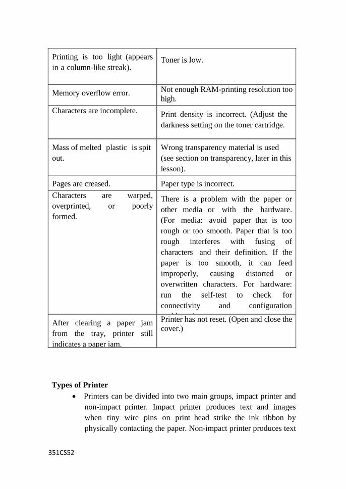
351CS52
Types of Printer
Printers can be divided into two main groups, impact printer and
non-impact printer. Impact printer produces text and images
when tiny wire pins on print head strike the ink ribbon by
physically contacting the paper. Non-impact printer produces text
Printing is too light (appears
in a column-like streak).
Toner is low.
Memory overflow error. Not enough RAM-printing resolution too
high.
Characters are incomplete. Print density is incorrect. (Adjust the
darkness setting on the toner cartridge.
Mass of melted plastic is spit
out.
Wrong transparency material is used
(see section on transparency, later in this
lesson). Pages are creased.
Paper type is incorrect.
Characters are warped,
overprinted, or poorly
formed.
There is a problem with the paper or
other media or with the hardware.
(For media: avoid paper that is too
rough or too smooth. Paper that is too
rough interferes with fusing of
characters and their definition. If the
paper is too smooth, it can feed
improperly, causing distorted or
overwritten characters. For hardware:
run the self-test to check for
connectivity and configuration
problems.) After clearing a paper jam
from the tray, printer still
indicates a paper jam.
Printer has not reset. (Open and close the
cover.)

351CS52
and graphics on paper without actually striking the paper.
Printers can also be categorized based on the print method or
print technology. The most popular ones are inkjet printer,
laser printer, dot-matrix printer and thermal printer. Among
these, only dot-matrix printer is impact printer and the others
are non-impact printers.
Some printers are named because they are designed for
specific functions, such as photo printers, portable printers and
all-in-one / multifunction printers. Photo printers and portable
printers usually use inkjet print method whereas multifunction
printers may use inkjet or laser print method.
Inkjet printers and laser printers are the most popular printer
types for home and business use. Dot matrix printer was popular
in 70‘s and 80‘s but has been gradually replaced by inkjet
printers for home use. However, they are still being used to
print multi-part forms and carbon copies for some businesses.
The use of thermal printers is limited to ATM, cash registers and
point-of-sales terminals. Some label printers and portable
printers also use thermal printing.
Due to the popularity of digital camera, laptop and SoHo office
(small office / home office), the demand for photo printers,
portable printers and multifunction printers has also increased
substantially in recent years.
Popular Printers:
Inkjet printers
Laser printers
Less Popular Printers:
Dot-matrix printers
Thermal printers
351CS52
Specialty Printers:
Photo printers
SWITCH-MODE POWER SUPPLY:
Power electronics deals with four forms of power conversion.
1. ac-dc conversion called rectification
2. ac-ac conversion ,
3. dc-ac conversion and
4. dc-dc conversion.
DC-DC converters were referred to as choppers earlier, when SCRs
were used. Nowadays, IGBTs and MOSFETs are the devices used
for dc-dc conversion and these circuits can be classified as switch
mode power supply circuits. The abbreviation or acronym for
switch mode power supply is SMPS.
A switch mode power supply circuit is versatile. It can be used to:
Step down an unregulated dc input voltage to produce a regulated dc
output voltage using a circuit known as Buck Converter or Step-Down
SMPS,
Step up an unregulated dc input voltage to produce a regulated
dc output voltage using a circuit known as Boost Converter or
Step-Up SMPS,
Step up or step down an unregulated dc input voltage to produce a
regulated dc output voltage ,
Invert the input dc voltage using usually a circuit such as the Cuk
converter, and
Produce multiple dc outputs using a circuit such as the fly-back
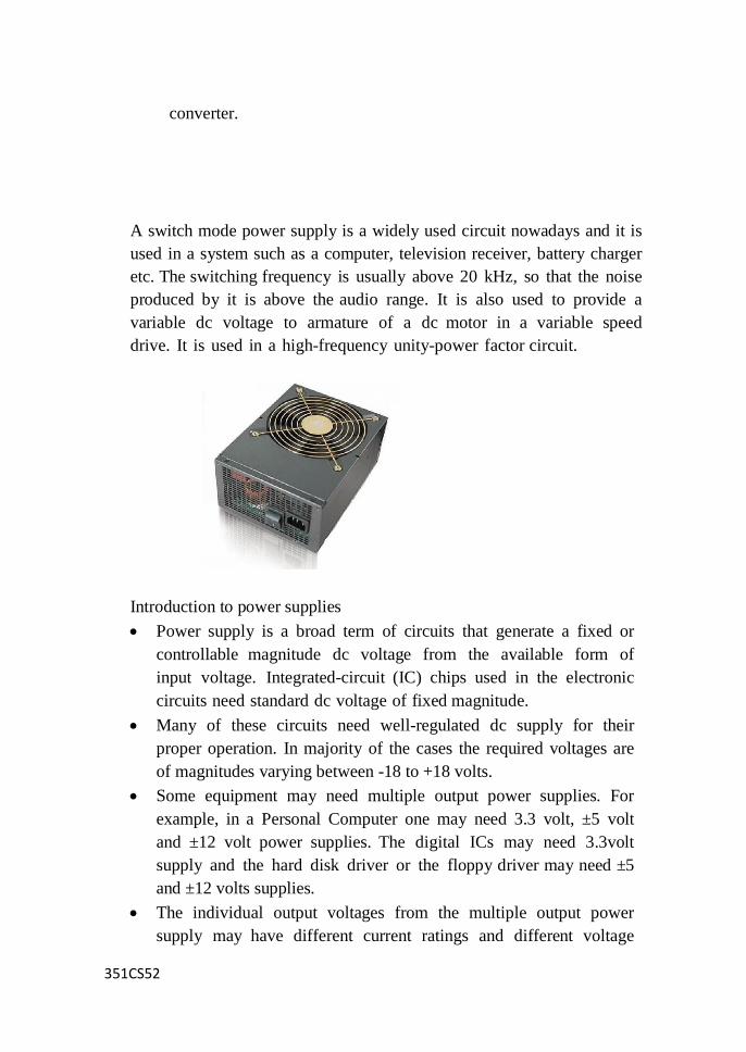
351CS52
converter.
A switch mode power supply is a widely used circuit nowadays and it is
used in a system such as a computer, television receiver, battery charger
etc. The switching frequency is usually above 20 kHz, so that the noise
produced by it is above the audio range. It is also used to provide a
variable dc voltage to armature of a dc motor in a variable speed
drive. It is used in a high-frequency unity-power factor circuit.
Introduction to power supplies
Power supply is a broad term of circuits that generate a fixed or
controllable magnitude dc voltage from the available form of
input voltage. Integrated-circuit (IC) chips used in the electronic
circuits need standard dc voltage of fixed magnitude.
Many of these circuits need well-regulated dc supply for their
proper operation. In majority of the cases the required voltages are
of magnitudes varying between -18 to +18 volts.
Some equipment may need multiple output power supplies. For
example, in a Personal Computer one may need 3.3 volt, ±5 volt
and ±12 volt power supplies. The digital ICs may need 3.3volt
supply and the hard disk driver or the floppy driver may need ±5
and ±12 volts supplies.
The individual output voltages from the multiple output power
supply may have different current ratings and different voltage
351CS52
regulation requirements. Almost invariably these outputs are
isolated dc voltages where the dc output is ohmically isolated
from the input supply. In case of multiple output supplies
ohmic isolation between two or more outputs may be desired.
The input connection to these power supplies is often taken from
the standard utility power plug point (ac voltage of 115V / 60Hz
or 230V / 50Hz). It may not be unusual, though, to have a
power supply working from any other voltage level which could
be of either ac or dc type.
There are two broad categories of power supplies: Linear
regulated power supply and switched mode power supply
(SMPS). In some cases one may use a combination of switched
mode and linear power supplies to gain some desired advantages
of both the types.
Liner Regulated power supply
A linear power supply operating from an unregulated dc input.
This kind of unregulated dc voltage is most often derived from the utility
ac source.
The utility ac voltage is first stepped down using a utility
frequency transformer, then it is rectified using diode rectifier
and filtered by placing a capacitor across the rectifier output.
The voltage across the capacitor is still fairly unregulated and is
load dependent. The ripple in the capacitor voltage is not only
dependent on the capacitance magnitude but also depends on load
and supply voltage variations.
The unregulated capacitor voltage becomes the input to the
linear type power supply circuit.
The filter capacitor size is chosen to optimize the overall cost and
volume.
However, unless the capacitor is sufficiently large the capacitor
voltage may have unacceptably large ripple.
The representative rectifier and capacitor voltage waveforms,
where a 100 volts (peak), 50 Hz ac voltage is rectified and
filtered using a capacitor of 1000 micro-farad and fed to a load of
100 ohms
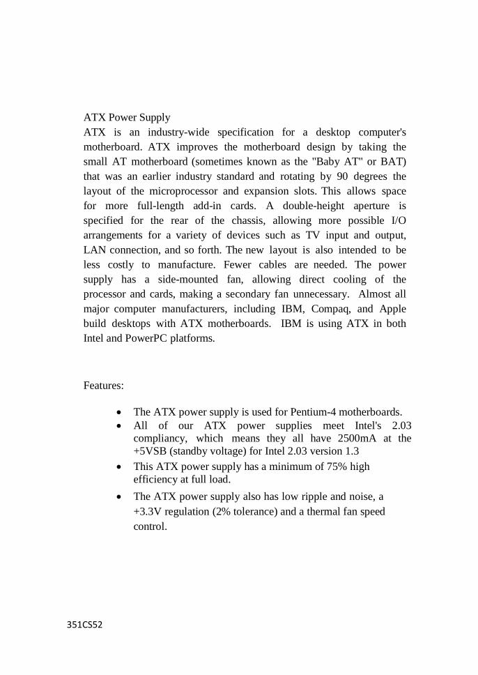
351CS52
ATX Power Supply
ATX is an industry-wide specification for a desktop computer's
motherboard. ATX improves the motherboard design by taking the
small AT motherboard (sometimes known as the "Baby AT" or BAT)
that was an earlier industry standard and rotating by 90 degrees the
layout of the microprocessor and expansion slots. This allows space
for more full-length add-in cards. A double-height aperture is
specified for the rear of the chassis, allowing more possible I/O
arrangements for a variety of devices such as TV input and output,
LAN connection, and so forth. The new layout is also intended to be
less costly to manufacture. Fewer cables are needed. The power
supply has a side-mounted fan, allowing direct cooling of the
processor and cards, making a secondary fan unnecessary. Almost all
major computer manufacturers, including IBM, Compaq, and Apple
build desktops with ATX motherboards. IBM is using ATX in both
Intel and PowerPC platforms.
Features:
The ATX power supply is used for Pentium-4 motherboards.
All of our ATX power supplies meet Intel's 2.03
compliancy, which means they all have 2500mA at the
+5VSB (standby voltage) for Intel 2.03 version 1.3
This ATX power supply has a minimum of 75% high
efficiency at full load.
The ATX power supply also has low ripple and noise, a
+3.3V regulation (2% tolerance) and a thermal fan speed
control.
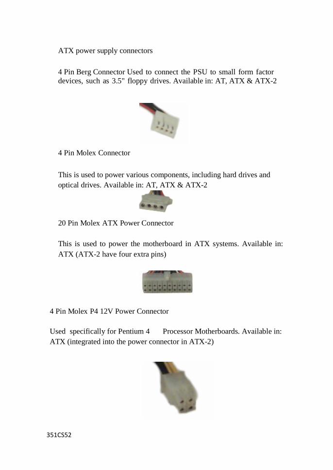
351CS52
ATX power supply connectors
4 Pin Berg Connector Used to connect the PSU to small form factor
devices, such as 3.5" floppy drives. Available in: AT, ATX & ATX-2
4 Pin Molex Connector
This is used to power various components, including hard drives and
optical drives. Available in: AT, ATX & ATX-2
20 Pin Molex ATX Power Connector
This is used to power the motherboard in ATX systems. Available in:
ATX (ATX-2 have four extra pins)
4 Pin Molex P4 12V Power Connector
Used specifically for Pentium 4 Processor Motherboards. Available in:
ATX (integrated into the power connector in ATX-2)
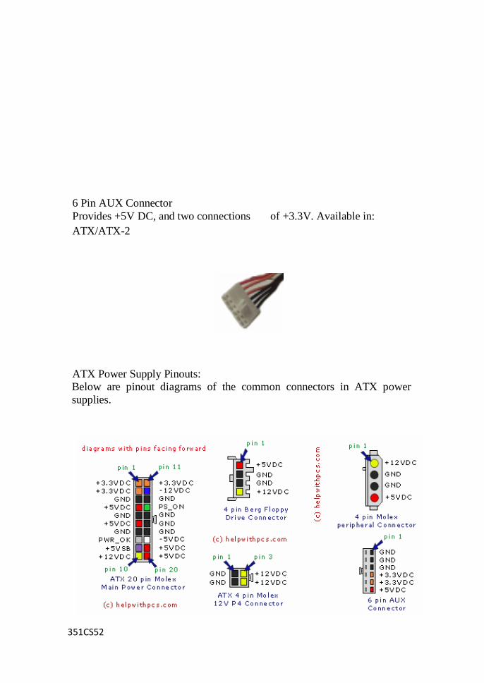
351CS52
6 Pin AUX Connector
Provides +5V DC, and two connections of +3.3V. Available in:
ATX/ATX-2
ATX Power Supply Pinouts:
Below are pinout diagrams of the common connectors in ATX power
supplies.
351CS52
A scanner is just another input device, much like a keyboard or mouse,
except that it takes its input in graphical form. These images could
be photographs for retouching, correction or use in DTP. They could
be hand-drawn logos required for document letterheads. They could
even be pages of text which suitable software could read and save as
an editable text file.
The list of scanner applications is almost endless, and has resulted
in products evolving to meet specialist requirements:
high-end drum scanners, capable of scanning both reflective art
and transparencies, from 35mm slides to 16-foot x 20in material
at high (10,000dpi+) resolutions
compact document scanners, designed exclusively for OCR and
document management
dedicated photo scanners, which work by moving a photo over a
stationary light source
slide/transparency scanners, which work by passing light through
an image rather than reflecting light off it
hand held scanners, for the budget end of the market or for those
with little desk space.
However, flatbed scanners are the most versatile and popular format.
These are capable of capturing colour pictures, documents, pages from
books and magazines, and, with the right attachments, even scan
transparent photographic film.
Scanner Image:
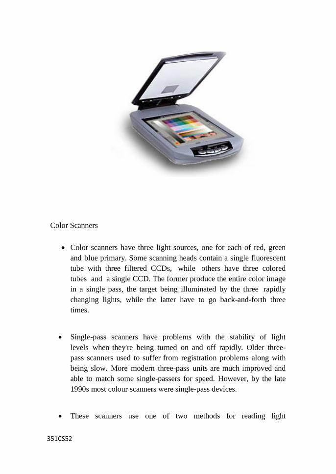
351CS52
Color Scanners
Color scanners have three light sources, one for each of red, green
and blue primary. Some scanning heads contain a single fluorescent
tube with three filtered CCDs, while others have three colored
tubes and a single CCD. The former produce the entire color image
in a single pass, the target being illuminated by the three rapidly
changing lights, while the latter have to go back-and-forth three
times.
Single-pass scanners have problems with the stability of light
levels when they're being turned on and off rapidly. Older three-
pass scanners used to suffer from registration problems along with
being slow. More modern three-pass units are much improved and
able to match some single-passers for speed. However, by the late
1990s most colour scanners were single-pass devices.
These scanners use one of two methods for reading light
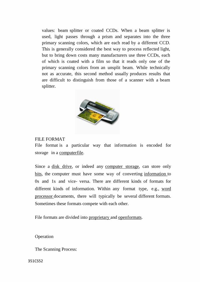
351CS52
values: beam splitter or coated CCDs. When a beam splitter is
used, light passes through a prism and separates into the three
primary scanning colors, which are each read by a different CCD.
This is generally considered the best way to process reflected light,
but to bring down costs many manufacturers use three CCDs, each
of which is coated with a film so that it reads only one of the
primary scanning colors from an unsplit beam. While technically
not as accurate, this second method usually produces results that
are difficult to distinguish from those of a scanner with a beam
splitter.
FILE FORMAT
File format is a particular way that information is encoded for
storage in a computer file.
Since a disk drive, or indeed any computer storage, can store only
bits, the computer must have some way of converting information to
0s and 1s and vice- versa. There are different kinds of formats for
different kinds of information. Within any format type, e.g., word
processor documents, there will typically be several different formats.
Sometimes these formats compete with each other.
File formats are divided into proprietary and open formats.
Operation
The Scanning Process:

351CS52
The document is placed on the glass plate and the cover is closed.
The inside of the cover in most scanners is flat white, although a
few are black. The cover provides a uniform background that the
scanner Software can use as a reference point for determining the
size of the document being scanned. Most flatbed scanners allow the
cover to be removed for scanning a bulky object, such as a page
in a thick book.
A lamp is used to illuminate the document. The lamp in newer
scanners is either a cold cathode fluorescent lamp (CCFL) or a
xenon lamp, while older scanners may have a standard fluorescent
lamp.
The entire mechanism (mirrors, lens, filter and CCD array) make up
the scan head. The scan head is moved slowly across the
document by a belt that is attached to a stepper motor. The
scan head is attached to a stabilizer bar to ensure that there is no
wobble or deviation in the pass. Pass means that the scan head has
completed a single complete scan of the document.
The image of the document is reflected by an angled mirror to
another mirror. In some scanners, there are only two mirrors
while others use a three mirror approach. Each mirror is slightly
curved to focus the image it reflects onto a smaller surface.
The last mirror reflects the image onto a lens. The lens
focuses the image through a filter on the CCD array.
The filter and lens arrangement vary based on the scanner.
Some scanners use a three pass scanning method. Each pass
uses a different color filter (red, green or blue) between the
lens and CCD array. After the three passes are completed, the
scanner software assembles the three filtered images into a
single full-color image.
Most scanners today use the single pass method. The lens splits the
image into three smaller versions of the original. Each smaller version
351CS52
passes through a color filter (either red, green or blue) onto a discrete
section of the CCD array. The scanner combines the data from the
three parts of the CCD array into a single full-color image.
Another imaging array technology that has become popular in
inexpensive flatbed scanners is contact image sensor (CIS). CIS
replaces the CCD array, mirrors, filters, lamp and lens with
rows of red, green and blue light emitting diodes (LEDs). The
image sensor mechanism, consisting of 300 to 600 sensors
spanning the width of the scan area, is placed very close to the glass
plate that the document rests upon. When the image is scanned, the
LEDs combine to provide white light. The illuminated image is
then captured by the row of sensors. CIS scanners are cheaper,
lighter and thinner, but do not provide the same level of quality
and resolution found in most CCD scanners
The sensor component itself is implemented using one of three
different types of technology:
PMT (photomultiplier tube), a technology inherited from the
drum scanners of yesteryear
CCD (charge-coupled device), the type of sensor used in desktop
scanners
CIS (contact image sensor), a newer technology which
integrates scanning functions into fewer components, allowing
scanners to be more compact in size.
Scan modes
PCs represent pictures in a variety of ways - the most common methods
being are line art, halftone, grayscale, and color:
Line art is the smallest of all the image formats. Since only
black and white information is stored, the computer represents
black with a 1 and white with a 0. It only takes 1-bit of data to
store each dot of a black and white scanned image. Line art is

351CS52
most useful when scanning text or line drawing. Pictures do
not scan well in line art mode.
While computers can store and show grayscale images, most
printers are unable to print different shades of gray. They use
a trick called halftoning. Halftones use patterns of dots to fool
the eye into believing it is seeing grayscale information
Grayscale images are the simplest of images for the
computer to store.
Humans can perceive about 255 different shades of grey -
represented in a PC by a single byte of data with the value 0 to 255.
A grayscale image can be thought of as equivalent to a black and
white photograph
True color images are the largest and most complex images to
store, PCs using 8-bits (1 byte) to represent each of the color
components (red, green, and blue) and therefore 24-bits in total to
represent the entire color spectrum.
Types of Scanners
Scanners have become an important part of the home office over the
last few years. Scanner technology is everywhere and used in many ways:
Flatbed scanners, also called desktop scanners, are the most
versatile and commonly used scanners. In fact, this article will
focus on the technology as it relates to flatbed scanners.
Sheet-fed scanners are similar to flatbed scanners except the
document is moved and the scan head is immobile. A sheet-fed
scanner looks a lot like a small portable printer.
Handheld scanners use the same basic technology as a flatbed
scanner, but rely on the user to move them instead of a
motorized belt. This type of scanner typically does not provide
good image quality. However, it can be useful for quickly
capturing text.
Drum scanners are used by the publishing industry to capture
incredibly detailed images. They use a technology called a
photomultiplier tube (PMT). In PMT, the document to be

351CS52
scanned is mounted on a glass cylinder. At the center of the
cylinder is a sensor that splits light bounced from the
document into three beams. Each beam is sent through a color
filter into a photomultiplier tube where the light is changed into
an electrical signal.
351CS52
UNIT – V
TROUBLESHOOTING PC
Anti-virus Software
Antivirus software is a computer program that detects, prevents, and
takes action to disarm or remove malicious software programs, such
as viruses and worms. You can help protect your computer against
viruses by using antivirus software. Computer viruses are software
programs that are deliberately designed to interfere with computer
operation, record, corrupt, or delete data, or spread themselves to other
computers and throughout the Internet. To help prevent the most current
viruses, you must update your antivirus software regularly. You can set
up most types of antivirus software to update automatically.
Anti-virus software packages:
These anti virus software‘s are called ‗Virus Scanners‘. Virus
scanners are program which search system areas as well as program
files for known virus infections. These scanner program searches for
a specific virus cod sequences called signatures within a normal
program to check for any virus infection. These scanner programs may be
memory resident or a normal file type.
A memory resident virus detection program is loaded in the RAM
while the system is booting, and it is active as long as the system is ON,
whenever a program is copied into RAM it checks for the known virus
code or the signature and tells about the infection. Or in some cases it
informs whenever the boot record (or) a file is about to modify.
351CS52
PC-Clean is antivirus scanner software available in Windows 95
environments. Vx2000 is another anti -virus scanner software used in
Novell Netware LAN environments and Dr.Solomon is virus scanning
software used both in DOS and windows environments.
How to choose the best antivirus software?
The number of new computer viruses is rising every year and they are
getting more malicious than before. In 2003, 7 new viruses were
unleashed every day. In 2004, more than 10,000 new computer viruses
were identified, many of them have several variants. Computer viruses,
computer worms and Trojan horses spread through the network by
sharing diskettes, downloading files from the internet and email
attachments. To protect your computer, always use the best antivirus
software from reputable publishers and update it regularly. Do not
open suspicious files or attachments even if they come from people in your
address book.
The Best Antivirus Software usually have several characteristics:
They come from well known reputable publishers. Be wary if you
have never heard of the name of the antivirus programs or the
software publishers. Do not run any free downloads or free
scans unless you have researched about the software publishers.
Installing a poorly designed program or one which is accompanied
by hidden applications (such as spyware/adware) will do more
harm than good to your computer. They may damage your
system, create security holes and give you a false sense of
security.

351CS52
The software are user friendly, i.e. they are easy to install and easy to
use.
They provide rich features, including real time protection, stopping
computer viruses, worms and Trojan horses before they infect
the computer, scanning of incoming and outgoing email, instant
messages, and employing advanced worm stopping and script
stopping technology.
The software publishers update their detection database frequently
and release new version regularly. The antivirus software should
have the option of automatic update.
Provide good and prompt technical support, such as live message,
email and phone support.
Computer viruses are just one of the IT security problems,
hackers and spyware / adware are two other major threats.
Although antivirus programs can now detect and remove some
spyware programs, they cannot stop hacker attacks, nor can they
detect most of the spyware programs which are usually installed
with other applications or free download.
Anti-Virus Software:
McAfee Virus Scan
AVG
PC Security ShieldAVG Antivirus
Kaspersky Anti-Virus
Avecho
Panda Antivirus
F-Secure
Norton Anti-Virus
Sophos Anti-Virus
How Computer Viruses Work
Strange as it may sound, the computer virus is something of an
Information Age marvel. On one hand, viruses show us how vulnerable

351CS52
we are -- a properly engineered virus can have a devastating effect,
disrupting productivity and doing billions of dollars in damages. On the
other hand, they show us how sophisticated and interconnected human
beings have become.
Viruses - A virus is a small piece of software that piggybacks
on real programs. For example, a virus might attach itself to a
program such as a spreadsheet program. Each time the
spreadsheet program runs, the virus runs, too, and it has the
chance to reproduce (by attaching to other programs) or wreak
havoc.
E-mail viruses - An e-mail virus travels as an attachment
toe-mail messages, and usually replicates itself by automatically
mailing itself to dozens of people in the victim's e-mail address
book. Some e-mail viruses don't even require a double-click --
they launch when you view the infected message in the preview
pane of your e-mail software [source: Johnson].
Trojan horses - A Trojan horse is simply a computer
program. The program claims to do one thing (it may claim to
be a game) but instead does damage when you run it (it may
erase your hard disk). Trojan horses have no way to replicate
automatically.
Worms - A worm is a small piece of software that uses
computer networks and security holes to replicate itself. A copy
of the worm scans the network for another machine that has
a specific security hole. It copies itself to the new machine
using the security hole, and then starts replicating from there, as
well.
What is a computer virus?
A computer virus is a computer program that can infect your computer
system by executing itself without your permission or knowledge
and run against your wishes. Viruses can also replicate itself to
maximize the infection.
351CS52
What is a computer program?
A computer program is a list of instruction for a computer to execute.
Basically, people create computer programs to do good things such
as music player, video player, email programs, calculator and many
more. They are all helpful program which bring benefits to the
people. Unfortunately, some people write programs to do bad things
such as programs that might corrupt or delete your files or documents
on your hard drive or programs that might send your private data (ex.
credit card number) to strangers or to the writer himself. This kind of
program is known as computer virus.
Why we call it a VIRUS?
Well, it‘s just like a human virus, it can be very dangerous and
destructive. It can also spread itself from one computer to another by
many ways. For instance, viruses are most easily spread by
attachments in e-mail messages or instant messaging messages over
the network or the internet. Viruses are also easily spread by
carrying it on a removable medium such as floppy disk, USB drive or
CD.
What is the difference between viruses, worms and Trojan horses?
Some people distinguish between general viruses, worms and Trojan
horses. A worm is a special type of malware programs that can
replicate itself and use memory, but cannot attach itself to other
programs, and a Trojan horse is a file that appears harmless until
executed.
Firewall:
A firewall is a set of related programs, located at a network gateway
server, that protects the resources of a private network from users
351CS52
from other networks. (The term also implies the security policy that is
used with the programs.) An enterprise with an intranet that allows its
workers access to the wider Internet installs a firewall to prevent
outsiders from accessing its own private data resources and for
controlling what outside resources its own users have access to.
Basically, a firewall, working closely with a router program,
examines each network packet to determine whether to forward it
toward its destination. A firewall also includes or works with a proxy
server that makes network requests on behalf of workstation users. A
firewall is often installed in a specially designated computer separate
from the rest of the network so that no incoming request can get
directly at private network resources.
There are a number of firewall screening methods. A simple one is
to screen requests to make sure they come from acceptable
(previously identified) domain name and Internet Protocol
addresses. For mobile users, firewalls allow remote access in to the
private network by the use of secure logon procedures and
authentication certificates.
A number of companies make firewall products. Features include
logging and reporting, automatic alarms at given thresholds of
attack, and a graphical user interface for controlling the firewall.
Computer security borrows this term from firefighting, where it
originated. In firefighting, a firewall is a barrier established to prevent
the spread of fire.
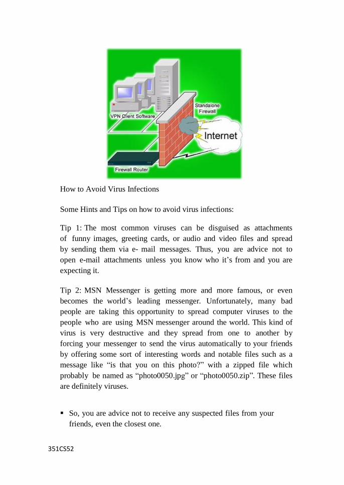
351CS52
How to Avoid Virus Infections
Some Hints and Tips on how to avoid virus infections:
Tip 1: The most common viruses can be disguised as attachments
of funny images, greeting cards, or audio and video files and spread
by sending them via e- mail messages. Thus, you are advice not to
open e-mail attachments unless you know who it‘s from and you are
expecting it.
Tip 2: MSN Messenger is getting more and more famous, or even
becomes the world‘s leading messenger. Unfortunately, many bad
people are taking this opportunity to spread computer viruses to the
people who are using MSN messenger around the world. This kind of
virus is very destructive and they spread from one to another by
forcing your messenger to send the virus automatically to your friends
by offering some sort of interesting words and notable files such as a
message like ―is that you on this photo?‖ with a zipped file which
probably be named as ―photo0050.jpg‖ or ―photo0050.zip‖. These files
are definitely viruses.
So, you are advice not to receive any suspected files from your
friends, even the closest one.
351CS52
You should judge a file by its size with your common sense.
You should ask your friend once again to determine whether or not
they are really there to send you something, but not the auto-virus.
Tip 3: Viruses are easily spread by carrying it on a removable
medium such as floppy disk, USB drive or CD.
Therefore, you should always scan diskettes, CD‘s and any other
removable media before using them.
Tip 4: Internet is the main media for virus to spread. Every
downloadable file may consists of viruses.
You should always scan files downloaded from the Internet
before using them.
You are advice not to install any unapproved software on your
computer.
Tip 5: The General tip to avoid virus infection.
An anti-virus software must be installed in your computer.
Ensure that your anti-virus software is up to date.
Ensure that your operating system is up to date and patched with
the latest security updates. For instance, you should enable
Windows Update if you are using Microsoft Windows Operating
System.
Scan your computer on a regular basis.
Install and run a firewall on your computer.
How to Find Computer Virus
Computer viruses are small applications that contaminate files inside
your computer and are capable of transferring from one computer to
another. The purpose of the virus is to spread and corrupt a computer‘s
system. Infected computers start to slow down until the entire system
eventually crash or malfunction. Antivirus programs are sold all over the
351CS52
world to fight virus infestation that has now found a way to disguise itself
to infiltrate low level computer security. To find a virus, you will need to
have an antivirus program.
Materials Needed
Step 1
Install an antivirus program. Secure a licensed antivirus
program from a reputable antivirus company. Antivirus
programs are available online via downloading or offline
via CD or DVD copy.
Step 2
After installing your antivirus program run an immediate
update of the software. Antivirus updates are important as
some antivirus employs signatures to recognize viruses.
Signature is a traditional process to identify malicious files.
It identifies viruses by checking the contents of a file or a
program against its data base of viruses. Updating your
antivirus program would also mean updating your virus
database of the newly identified viruses. Nowadays, well
known antivirus companies also employ heuristics to
identify viruses and other malicious files. Heuristic is a
process in which an antivirus program analyzes files and
programs command lines to be able to identify if they are
malicious and harmful.
Step 3
Another way to find a computer virus is to check manually.
Go to Control Panel. Click on the Start then select Control
Panel from the Start Menu.
Step 4
Select Add or Remove Programs from the Control Panel
window. Check on the list of programs installed in your
computer.
Step 5
Note the names of the programs you are not familiar with.
Step 6
351CS52
Check the program‘s name on the Internet. Research about
its functions and possible effects on your system.
Step 7
If this file was indeed malicious delete it at once. If you
are not sure if a file is malicious do not delete anything as
it might affect your computer‘s system and cause even
greater damage.
Step 8
Another way to find a virus in your computer is to check
the Windows Start-up folder. To go to Windows Start-up
folder select My Computer. Select Drive C: from My
Computer.
Step 9
Select the Documents and Settings folder in Drive C: Go to
the All Users folder in the Documents and Settings. Inside the
Documents and Settings click on the Start Menu folder.
Check the programs inside the Start Menu folder. Identify
listed programs that you do not recognize and research on
them. This way you would be able to find out which files are
harmful or a part of your computer‘s system.
Types of Computer Virus
Computer viruses can be classified into six groups:
1. Boot or partition infecting viruses
2. Executable file infecting viruses
3. Multipart viruses
4. Directory infecting viruses
5. Hardware infecting viruses
6. Network infecting viruses
351CS52
All these six types of viruses can be further classified into resident and
non resident types.
Resident Viruses Resident viruses are those which install their code in
memory on execution and infect other programmes or disk from there.
Non Resident Viruses The first sector containing the code to load and
start the operating system is called the boot sector in any floppy
diskette. These type of viruses modify the boot sector of the floppy disks.
This leads to boot the system.
Partition Table Viruses The first physical sector in any hard disk is called
master boot record which contains booting information and also the
partition table information in the hard disk. These viruses modify the
partition table and lead to unrecoverable data from the hard disk.
File Virus All viruses that modify executable program files to replicate
or spread are called fie viruses. These viruses infect the files with
filename extension .COM, EXE, DLL or executable regardless of their
extension.
Multipart Viruses These viruses infect both boot sectors as well as files.
These are dangerous viruses as they infect all parts of the diskettes.
Directory Viruses These viruses infect the directory information in any
diskettes and spread fastly. These viruses use an undocumented DOS
structure to point the start of every executable file to an area of the disk
where the virus code is written. Whenever a program is about to run, the
virus gets control and does whatever it is programmed to do, and then
loads the original programs in normal fashion. Here, it does not modify or
damage any files or boot sectors but infect the entire drives within
seconds.
351CS52
Hardware Infecting Viruses These viruses can damage hardware. These
viruses are known to reprogram the CRT chips to emit higher
frequencies and can cause the monitor to burn or. Also some of the
hardware infecting viruses keep moving the hard disk drives heads
randomly, this increased and unnecessary activity often damages hard disk
over a period of time.
Network Viruses These type of viruses spreads easily in a network
environment. They may be file virus, boot virus or a hardware virus.
Recently with the developments in Internet based networking
environments, these viruses are attached through the e-mail letters and
down loaded programs.
What is a Virus Signature?
In the antivirus world, a signature is an algorithm or hash (a number
derived from a string of text) that uniquely identifies a specific virus.
Depending on the type of scanner being used, it may be a static hash
which, in its simplest form, is a calculated numerical value of a
snippet of code unique to the virus. Or, less commonly, the
algorithm may be behavior-based, i.e. if this file tries to do X,Y,Z, flag
it as suspicious and prompt the user for a decision. Depending on the
antivirus vendor, a signature may be referred to as a signature, a definition
file, or a DAT file.
A single signature may be consistent among a large number of viruses.
This allows the scanner to detect a brand new virus it has never even
seen before. This ability is commonly referred to as either heuristics or
generic detection. Generic detection is less likely to be effective
against completely new viruses and more effective at detecting new
members of an already known virus 'family' (a collection of viruses that
share many of the same characteristics and some of the same code). The
ability to detect heuristically or generically is significant, given that
most scanners now include in excess of 250k signatures and the numbers

351CS52
of new viruses being discovered continues to increase dramatically year
after year.
The reoccurring need to update
Each time a new virus is discovered that is not detectable by an
existing signature, or may be detectable but cannot be properly removed
because its behavior is not totally consistent with previously known
threats, a new signature must be created. After the new signature has
been created and tested by the antivirus vendor, it is pushed out to the
customer in the form of signature updates. These updates add the
detection capability to the scan engine. In some cases, a previously
provided signature might be removed or replaced with a new signature
to offer better overall detection or disinfection capabilities.
Depending on the scanning vendor, updates may be offered hourly, or
daily, or sometimes even weekly. Much of the need to provide signatures
varies with the type of scanner it is, i.e. with what that scanner is charged
with detecting. For example, adware and spyware are not nearly as
prolific as viruses, thus typically an adware/spyware scanner may only
provide weekly signature updates (or even less often). Conversely, a
virus scanner must contend with thousands of new threats discovered
each month and therefore, signature updates should be offered at least
daily.
Of course, it's simply not practical to release an individual signature for
each new virus discovered, thus antivirus vendors tend to release on a
set schedule, covering all of the new malware they have encountered
during that time frame. If a particularly prevalent or menacing threat is
discovered between their regularly scheduled updates, the vendors will
typically analyze the malware, create the signature, test it, and release it
out-of-band (which means, release it outside of their normal update
schedule).
To maintain the highest level of protection, configure your antivirus
software to check for updates as often as it will allow. Keeping the
signatures up to date doesn't guarantee a new virus will never slip
351CS52
through, but it does make it far less likely.
Post
When IBM PCs were first introduced by IBM in1991, they included
safety features that had never been seen before in Personal computer.
These features were the POST and parity checked memory. The POST
is a series of program routines buried in the motherboard ROM
firmware. It tests all the main system components when power is turned
on. When we turn on an IBM compatible system, this program is
executed first before the system loads the operating system.
Functions:
Whenever a system is powered on, the computer automatically
performs a series of tests that check various components in the
system. The components tested by this procedure are the primary ones
such as the CPU, ROM, motherboard support circuitry, memory and major
peripherals. These tests are brief and not very through compared with the
other disk based diagnostics.
POST provides error or waring messages whenever a faulty
component is encountered. Two types of messages are provided:
Audio error codes and Display screen messages or codes. The POST
programs are stored in the BIOS ROM in the final 8KB area of 1MB
memory space. Immediately after power-on or reset, the
microprocessor starts instruction processing from the memory address
FFFF0 from where the POST begins.
IPL Hardware:
In order to begin POST successfully, certain minimum hardware
should be working properly. This minimum hardware is known as IPL
(Initial Program Load) hardware. After power-on or reset, the IPL
hardware transfers control to POST. The POST, after completion of all

351CS52
tests, transfers control to the bootstrap program which is read
either from floppy disk or hard disk. The IPL
hardware includes the following:
Power supply
Clock logic
Bus controller
Microprocessor
Address latches
Data bus and control bus transceivers
BIOS ROM
ROM address decode logic BIOS
Error Messages
Most BIOS systems display a three or four-digit error code along
with the error message to help pinpoint the apparent source of the
problem. The documentation for the BIOS system or your motherboard
should list the exact codes used on your PC‘s make and model.
The BIOS POST error codes are categorized by ROMs and services
and numbered in groups of 100. For example, a 600- series error,
such as a 601, 622, or 644 error code, indicates a problem with the
floppy disk drive or the floppy disk drive controller.
POST Boot Error codes:
Series Category
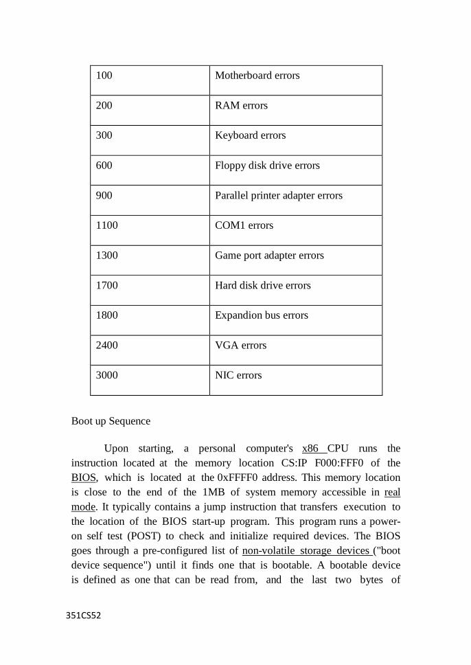
351CS52
100 Motherboard errors
200 RAM errors
300 Keyboard errors
600 Floppy disk drive errors
900 Parallel printer adapter errors
1100 COM1 errors
1300 Game port adapter errors
1700 Hard disk drive errors
1800 Expandion bus errors
2400 VGA errors
3000 NIC errors
Boot up Sequence
Upon starting, a personal computer's x86 CPU runs the
instruction located at the memory location CS:IP F000:FFF0 of the
BIOS, which is located at the 0xFFFF0 address. This memory location
is close to the end of the 1MB of system memory accessible in real
mode. It typically contains a jump instruction that transfers execution to
the location of the BIOS start-up program. This program runs a power-
on self test (POST) to check and initialize required devices. The BIOS
goes through a pre-configured list of non-volatile storage devices ("boot
device sequence") until it finds one that is bootable. A bootable device
is defined as one that can be read from, and the last two bytes of
351CS52
the first sector contai at the memory location CS:IP F000:FFF0 of
the BIOS, which is located at the 0xFFFF0 address. This memory
location is close to the end of the 1MB of system memory accessible in
real mode. It typically contains a jump instruction that transfers execution
to the location of the BIOS start-up program. This program runs a
power-on self test (POST) to check and initialize required devices. The
BIOS goes through a pre-configured list of non-volatile storage devices
("boot device sequence") until it finds one that is bootable. A bootable
device is defined as one that can be read from, and the last two
bytes of the first sector contain the word 0xAA55 (also known as the
boot signature).
Once the BIOS has found a bootable device it loads the boot sector
to hexadecimal Segment:Offset address 0000:7C00 or 07C0:0000 (maps
to the same ultimate address) and transfers execution to the boot code.
In the case of a hard disk, this is referred to as the master boot record
(MBR) and is often not operating system specific. The conventional MBR
code checks the MBR's partition table for a partition set as bootable (the
one with active flag set).[14] If an active partition is found, the MBR
code loads the boot sector code from that partition and executes it. The
boot sector is often operating-system-specific; however, in most
operating systems its main function is to load and execute the
operating system kernel, which continues startup. If there is no active
partition, or the active partition's boot sector is invalid, the MBR may
load a secondary boot loader which will select a partition (often via
user input) and load its boot sector, which usually loads the
corresponding operating system kernel.
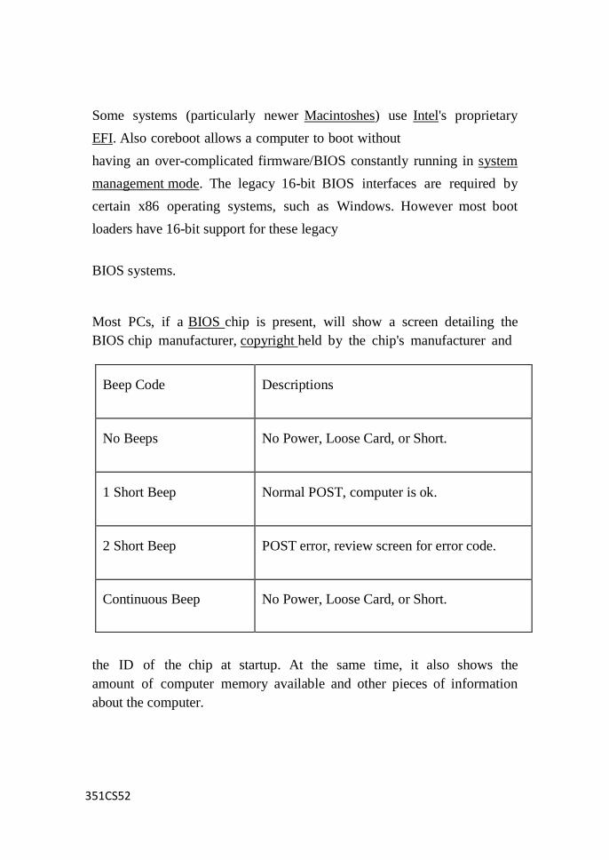
351CS52
Some systems (particularly newer Macintoshes) use Intel's proprietary
EFI. Also coreboot allows a computer to boot without
having an over-complicated firmware/BIOS constantly running in system
management mode. The legacy 16-bit BIOS interfaces are required by
certain x86 operating systems, such as Windows. However most boot
loaders have 16-bit support for these legacy
BIOS systems.
Most PCs, if a BIOS chip is present, will show a screen detailing the
BIOS chip manufacturer, copyright held by the chip's manufacturer and
the ID of the chip at startup. At the same time, it also shows the
amount of computer memory available and other pieces of information
about the computer.
Beep Code
Descriptions
No Beeps
No Power, Loose Card, or Short.
1 Short Beep
Normal POST, computer is ok.
2 Short Beep
POST error, review screen for error code.
Continuous Beep
No Power, Loose Card, or Short.
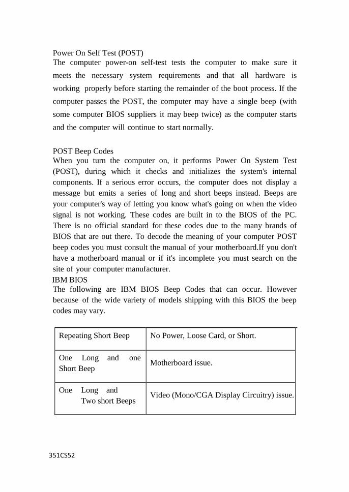
351CS52
Power On Self Test (POST)
The computer power-on self-test tests the computer to make sure it
meets the necessary system requirements and that all hardware is
working properly before starting the remainder of the boot process. If the
computer passes the POST, the computer may have a single beep (with
some computer BIOS suppliers it may beep twice) as the computer starts
and the computer will continue to start normally.
POST Beep Codes
When you turn the computer on, it performs Power On System Test
(POST), during which it checks and initializes the system's internal
components. If a serious error occurs, the computer does not display a
message but emits a series of long and short beeps instead. Beeps are
your computer's way of letting you know what's going on when the video
signal is not working. These codes are built in to the BIOS of the PC.
There is no official standard for these codes due to the many brands of
BIOS that are out there. To decode the meaning of your computer POST
beep codes you must consult the manual of your motherboard.If you don't
have a motherboard manual or if it's incomplete you must search on the
site of your computer manufacturer.
IBM BIOS
The following are IBM BIOS Beep Codes that can occur. However
because of the wide variety of models shipping with this BIOS the beep
codes may vary.
Repeating Short Beep No Power, Loose Card, or Short.
One Long and one
Short Beep
Motherboard issue.
One Long and
Two short Beeps
Video (Mono/CGA Display Circuitry) issue.
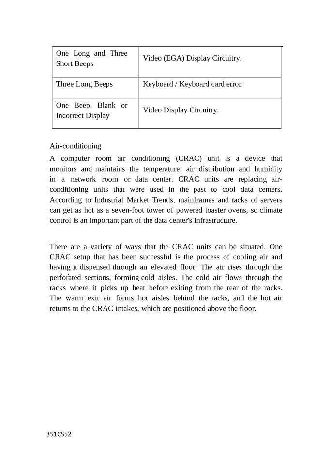
351CS52
One Long and Three
Short Beeps
Video (EGA) Display Circuitry.
Three Long Beeps Keyboard / Keyboard card error.
One Beep, Blank or
Incorrect Display
Video Display Circuitry.
Air-conditioning
A computer room air conditioning (CRAC) unit is a device that
monitors and maintains the temperature, air distribution and humidity
in a network room or data center. CRAC units are replacing air-
conditioning units that were used in the past to cool data centers.
According to Industrial Market Trends, mainframes and racks of servers
can get as hot as a seven-foot tower of powered toaster ovens, so climate
control is an important part of the data center's infrastructure.
There are a variety of ways that the CRAC units can be situated. One
CRAC setup that has been successful is the process of cooling air and
having it dispensed through an elevated floor. The air rises through the
perforated sections, forming cold aisles. The cold air flows through the
racks where it picks up heat before exiting from the rear of the racks.
The warm exit air forms hot aisles behind the racks, and the hot air
returns to the CRAC intakes, which are positioned above the floor.
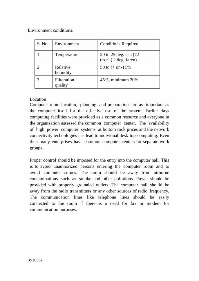
351CS52
Environment conditions:
S. No Environment Conditions Required
1 Temperature 20 to 25 deg. cen (72
(+or -) 2 deg. faren)
2 Relative
humidity
50 to (+ or -) 5%
3 Filteration
quality
45%, minimum 20%
Location
Computer room location, planning and preparation are as important as
the computer itself for the effective use of the system. Earlier days
computing facilities were provided as a common resource and everyone in
the organization assessed the common computer center. The availability
of high power computer systems at bottom rock prices and the network
connectivity technologies has lead to individual desk top computing. Even
then many enterprises have common computer centers for separate work
groups.
Proper control should be imposed for the entry into the computer hall. This
is to avoid unauthorized persons entering the computer room and to
avoid computer crimes. The room should be away from airborne
contaminations such as smoke and other pollutions. Power should be
provided with properly grounded outlets. The computer hall should be
away from the radio transmitters or any other sources of radio frequency.
The communication lines like telephone lines should be easily
connected to the room if there is a need for fax or modem for
communication purposes.
351CS52
Pollution
Computer room pollution:
Dirt, smoke, Dust and any other pollutants are not good for the system.
The suspended particles in the air will be carried through the system
and will be collected inside by the power supply cooling fan. The
following suggestions are given to avoid room pollution:
Shoes may be left outside the computer room to avoid dust
entering into the room.
An air curtain above the doorway may be provided to avoid
contamination's that can be carried in by the users.
Keyboards are impervious to liquids and dirt. Hence don‘t
permit drinks inside the computer room that may accidentally spill
over the keyboards.
Cigarette smoke causes corrosion in the internal connectors and
sockets of circuit boards. Hence smoking inside room may be
prohibited.
Keyboards are impervious to liquids and dirt. Hence don‘t
permit drinks inside the computer room that may accidentally spill
over the keyboards.
Cigarette smoke causes corrosion in the internal connectors and
sockets of circuit boards. Hence smoking inside room may be
prohibited.
Computer room should be kept clean, a vacuum cleaner may be
used periodically to remove the dust.
Humidifiers should not be used inside computer room because
water sprayed particles may affect computer system. Air
conditioners may be used to keep room cool and free from dust.
Periodically room fresheners may be used to refresh air and also
avoid bad smell.
351CS52
Power Supply
A clean AC power supply source is fundamental to the operations of
most sensitive electronic equipment‘s like computers, medical
equipment‘s and telecommunication systems. Of all the devices which
rely on AC power, computers are probably the most sensitive to power
disturbances and failures. In computer systems any power interruption
even of the order of milliseconds can cause loss of data, the entire system
to malfunction or fail, and loss of data, the entire system to malfunction or
fail, and loss of computer time resulting in extensive financial loss and
inconveniences.
Power Supply Problems
Nowadays the users of sophisticated electronic equipment are aware of
the problems with electrical power. The power supply which appears to
be clean and steady for many of the ordinary household appliances is not
suitable for computer systems. In many installations the power line that
the computer is connected to also serves heavy equipment. The switching
‗on‘ and ‗off‘ of these equipment may introduce voltage variations in the
line. The corrupted power comes in a number of forms, such as transient
disturbances, unstable voltage, dips and surges, noise, brownouts and
blackouts.
Transients: A transient is any brief change in power that doesn‘t repeat
itself. It can be an under voltage or an overvoltage. Sags (momentary
under voltage) and surges (momentary overvoltage) are transients.
Spikes and Surge: The deadliest power line problem is overvoltage. It is
lighting like high voltage that sneaks through the filter capacitor into
the computer and melts down its silicon circuitry. As its name implies an
overvoltage is pushing more voltage into the computer then it is equipped
to handle. The fluctuations may have a range of 10% of its rated voltage.
Spikes are high voltage transients which last for short duration of few
microseconds. Surges are high voltage transients which will last for
longer duration and will stretch for many milliseconds.
351CS52
Blackouts and Brownouts Besides overvoltage or over current
conditions other problems can occur with incoming power. They are
blackouts and brownouts. Due to under voltage without switching off if
the supply voltage dips or sags for a short duration is called brownouts.
Most PC‘s are designed to withstand prolonged voltage dips of about
20% without shutting down. Deeper dips or blackouts may switch off
the power good signal and shut down the computers suddenly. But they
can cause the most detrimental effect on equipment and data files.
UPS
Uninterruptible power supplies (UPSs) are devices that maintain the
supply of power to a load even when the AC input power is interrupted
or disturbed. This is typically accomplished by drawing the necessary
power from a stored energy source, such as a battery. UPSs may also
convert unregulated input power to voltage and frequency-filtered AC
power. Thus, the UPS will provide stable power and minimize the
effects of electric power supply disturbances and variations. UPSs are
currently found in commercial, industrial, medical and residential markets.
Applications include:
individual computers and computer systems
Shipboard systems
Automated manufacturing
Microprocessor- and microcontroller-based equipment
Medical applications Laboratories
Robotics
Precision motor-speed applications
Military applications
Mission-critical fields such as telecommunications and Internet nodes
Finance
Public health
Air traffic control
Transport
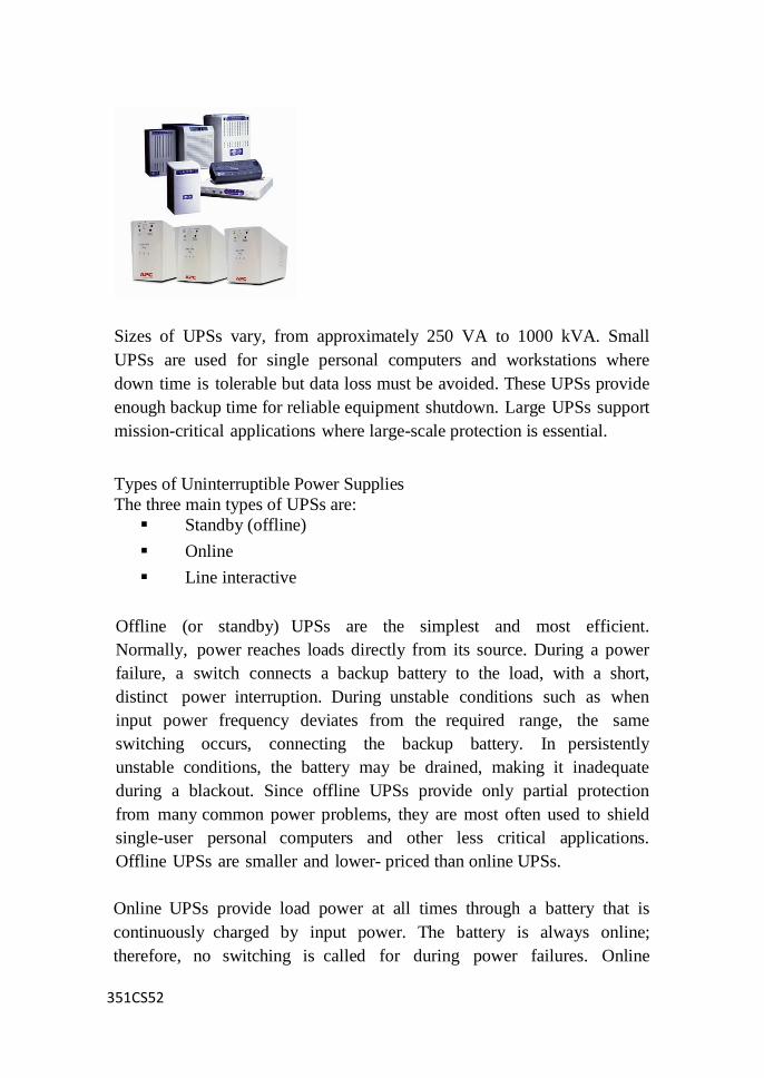
351CS52
Sizes of UPSs vary, from approximately 250 VA to 1000 kVA. Small
UPSs are used for single personal computers and workstations where
down time is tolerable but data loss must be avoided. These UPSs provide
enough backup time for reliable equipment shutdown. Large UPSs support
mission-critical applications where large-scale protection is essential.
Types of Uninterruptible Power Supplies
The three main types of UPSs are:
Standby (offline)
Online
Line interactive
Offline (or standby) UPSs are the simplest and most efficient.
Normally, power reaches loads directly from its source. During a power
failure, a switch connects a backup battery to the load, with a short,
distinct power interruption. During unstable conditions such as when
input power frequency deviates from the required range, the same
switching occurs, connecting the backup battery. In persistently
unstable conditions, the battery may be drained, making it inadequate
during a blackout. Since offline UPSs provide only partial protection
from many common power problems, they are most often used to shield
single-user personal computers and other less critical applications.
Offline UPSs are smaller and lower- priced than online UPSs.
Online UPSs provide load power at all times through a battery that is
continuously charged by input power. The battery is always online;
therefore, no switching is called for during power failures. Online

351CS52
UPSs provide complete protection and isolation from almost all types of
power problems and provide digital-quality power that is not possible with
offline systems. For these reasons, they are typically used for mission-
critical applications that demand high productivity and systems
availability. "Double-converter system" is another name for an online
UPS since it must convert AC input power to DC for charging the battery
and afterward convert DC to AC for use by the load. Double conversion
makes this UPS less efficient than other types. Online systems provide the
same benefits of an offline UPS combined with a line conditioner, at a
price lower than the cost of both components purchased separately.
Line-interactive UPSs retain some of the efficiency of offline UPSs while
providing the voltage regulation features of online systems. Instead of
converting the input power to DC and storing it in a battery, the UPS
sends the power to the load through a Ferro resonant transformer that
provides voltage regulation and power conditioning for disturbances
such as electrical line noise. In addition, when a power outage occurs,
the transformer maintains an energy reserve that is usually sufficient to
power most personal computers briefly during the switchover to the
UPS's battery power. In general, these UPSs work best with linear
loads such as motors, heaters and lights. Line-interactive UPSs are very
efficient, highly reliable and, unlike offline systems, offer voltage
regulation features.
Web Camera
A webcam is a video capture device connected to a computer or
computer network, often using a USB port or, if connected to a
network, ethernet or Wi-Fi. The most popular use is for video
telephony, permitting a computer to act as a videophone or video
conferencing station. This can be used in messenger programs such as
Windows Live Messenger, Skype and Yahoo messenger services.
Other popular uses, which include the recording of video files or even
still-images, are accessible via numerous software programs,
applications and devices. Webcams are known for low manufacturing
costs and flexibility, making them the lowest cost form of video telephony.
Related Documents