SCHOOL OF SCIENCE AND HUMANITIES DEPARTMENT OF PHYSICS UNIT – I - Fundamentals of Electrical Circuits Branch: B.Sc. Physics Subject: Electrical Wiring Batch: 2018-21 Subject Code: SPH1317

Welcome message from author
This document is posted to help you gain knowledge. Please leave a comment to let me know what you think about it! Share it to your friends and learn new things together.
Transcript

SCHOOL OF SCIENCE AND HUMANITIES
DEPARTMENT OF PHYSICS
UNIT – I - Fundamentals of Electrical Circuits
Branch: B.Sc. Physics Subject: Electrical Wiring
Batch: 2018-21 Subject Code: SPH1317

2
Resistors
• A resistor is a component that is used torestrict the flow of current in an electrical circuit
- somewhat analogous to a valve in a water line
Components & Symbols
variable
resistor
R
fixed
resistor
R
potentiometer
R
SCHEMATIC
SYMBOLS
3
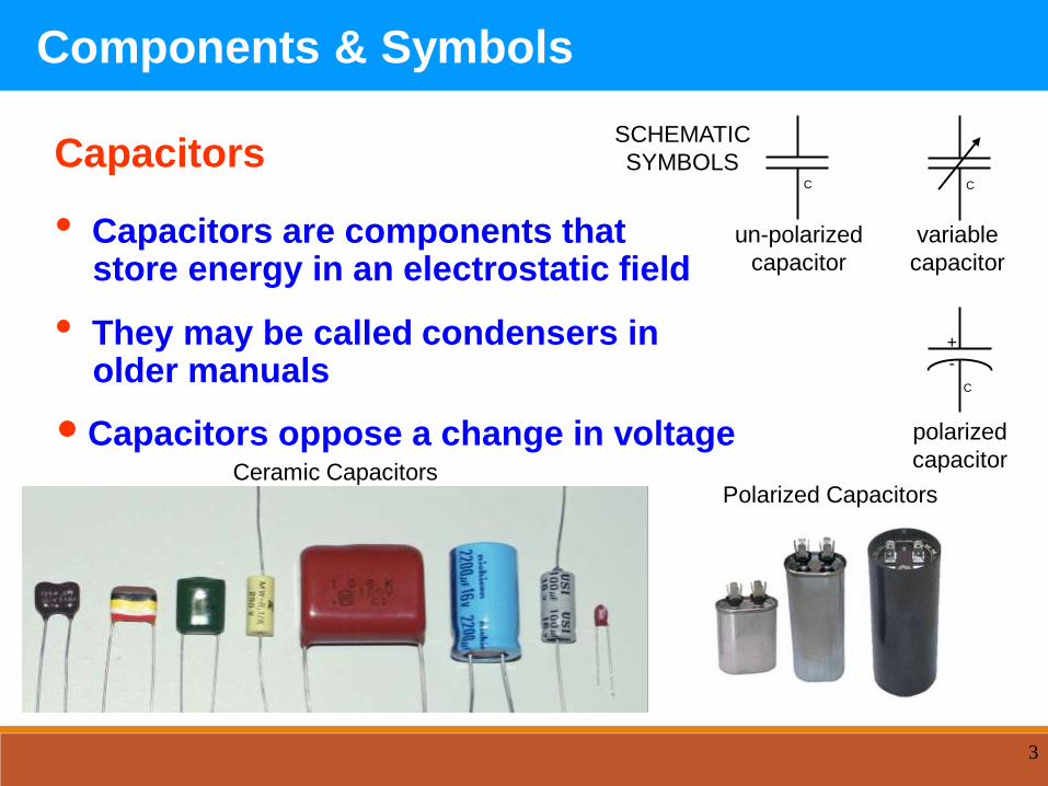
Capacitors
• Capacitors are components thatstore energy in an electrostatic field
• They may be called condensers in older manuals
•Capacitors oppose a change in voltage polarized
capacitor
C
+
-
variable
capacitor
CC
un-polarized
capacitor
SCHEMATIC
SYMBOLS
Ceramic CapacitorsPolarized Capacitors
Components & Symbols

DC & AC Fundamentals
5
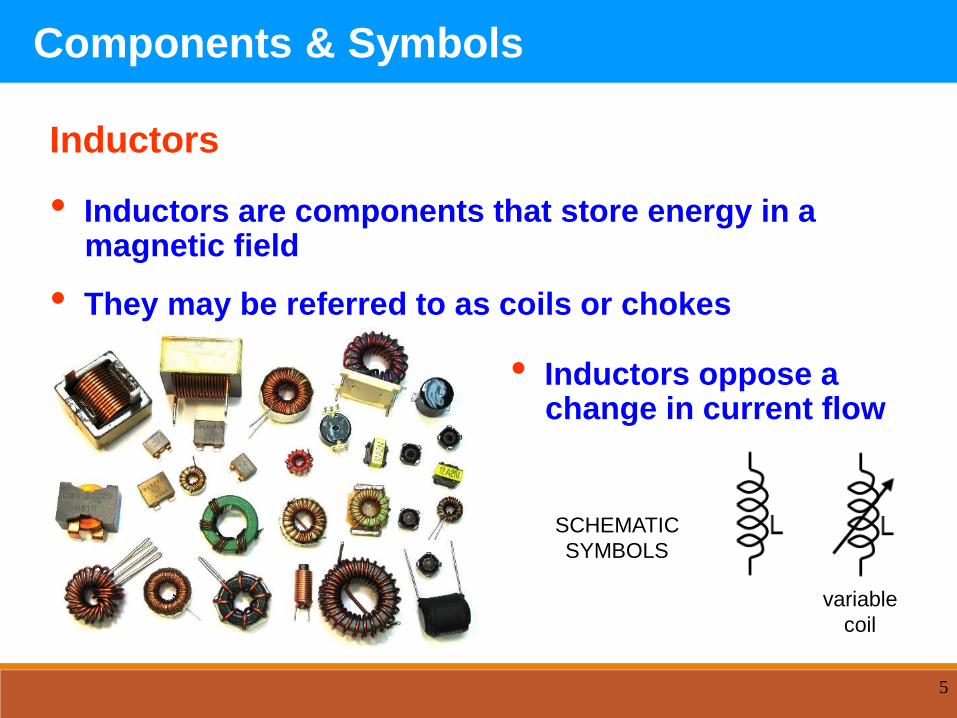
Inductors
• Inductors are components that store energy in a magnetic field
• They may be referred to as coils or chokes
SCHEMATIC
SYMBOLS
variable
coil
Components & Symbols
• Inductors oppose achange in current flow

6
Transformers
• Transformers are components that contain one or more inductors in a single structure
• Transformers are used to:
- change one voltage to another
- transfer electrical energy from
one circuit to another
Pole
Transformer
Power Transformer
Transformer
SCHEMATIC
SYMBOLS
tapped
transformer
Components & Symbols

7
Switches
• Switches are components used to make or break an electrical circuit
SPST
SPDT
DPST
SCHEMATIC
SYMBOLS
Components & Symbols

8
DC Voltage & Current
AC continually changes in
value
Household voltage =
120 volts rms
Household peak voltage =
155.16 volts peak
Household peak to peak voltage =
310.32 volts peak to peak
Electrical Meters
AC Voltage & Current
Amplitude of DC
DC (such as from a battery) does
not change in value from one
point in time to another point in
time
0 VOLTS
1.5 VOLTS
TIME
Amplitude of AC (AC SINE WAVE)
TIME

Electric Current
An electric potential difference causes electric charges to move
The flow of electric charge is called electric current Positive charge accelerates toward lower electric potential
Negative charge accelerates toward higher electric potential
The rate of flow of electric charge (I) through a conducting material is the amount of charge (Q) that flows divided by the time (t) it takes to flow, or
I = Q/t SI units are coulombs per second (C/s), called amperes (A),
where 1 coulomb/sec = 1 Ampere
By convention, electric current is defined as the flow of positive charge flowing from high potential (+) to low potential (-)

Resistance
The physical property of a material to “impede” the flow of electric charge is called electrical resistance
An object’s resistance (R) depends on:
Its inherent ability to conduct electricity, its resistivity ()
The surface area (A): the wider the area the more room for current to flow
The length (L) of the object: the longer the object themore material the current must be pushed through
R ~ L/A
Conductors (like metals) have low resistance
Insulators (plastics & non-metals) have high resistance
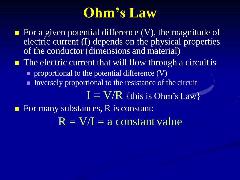
Ohm’s Law
For a given potential difference (V), the magnitude ofelectric current (I) depends on the physical propertiesof the conductor (dimensions and material)
The electric current that will flow through a circuit is proportional to the potential difference (V)
Inversely proportional to the resistance of the circuit
I = V/R {this is Ohm’s Law}
For many substances, R is constant:
R = V/I = a constant value
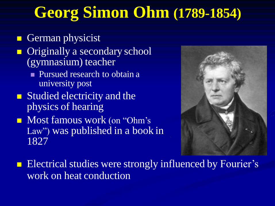
Georg Simon Ohm (1789-1854)
German physicist
Originally a secondary school (gymnasium) teacher Pursued research to obtain a
university post
Studied electricity and the physics of hearing
Most famous work (on “Ohm’s
Law”) was published in a book in 1827
Electrical studies were strongly influenced by Fourier’s work on heat conduction

Electric Power
It takes effort and energy (work) to drive electric charge through a circuit (against its resistance)
The rate of energy (power or P) required to drive electric current through a circuit (or part of a circuit) is proportional To the potential difference (V) across
To the electric current (I) that flows through a circuit
P=VI
The SI units of power are Volts (V) times amperes (A)
Joules per second (J/s)
Watts (W)

Direct Current (DC) & Alternating Current (AC)
When the power source running an electric circuit moves charge only one direction it is a direct current (DC) circuit Current flows from the high potential terminal (+) to the low
potential terminal (-)
In DC circuits, the power source supplies the electrons
Batteries and photoelectric cells produce DC current
When the power source driving an electric circuitmoves charge back-and-forth it is a an alternatingcurrent (AC) circuit In AC circuits, you supply the electrons
Our wall sockets typically fluctuate between +170 V and –170 V at a rate of 60 Hz
The fluctuating voltage has a sinusoidal waveform:

Alessandro Volta (1745-1827)
Italian physicist & inventor
First person to isolate methane
Fascinated with electricity at an early age
Pioneered the field of electrochemistry
Constructed the first battery to produce
electricity (called a voltaic pile)
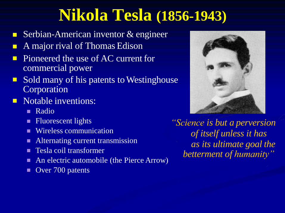
Nikola Tesla (1856-1943)
Serbian-American inventor & engineer
A major rival of Thomas Edison
Pioneered the use of AC current for commercial power
Sold many of his patents to Westinghouse Corporation
Notable inventions:Radio
Fluorescent lights
Wireless communication
Alternating current transmission
Tesla coil transformer
An electric automobile (the Pierce Arrow)
Over 700 patents
“Science is but a perversion
of itself unless it has as its ultimate goal the
betterment of humanity”

Electric Circuits
Power supply: provides the electric potential difference between its terminals A device that transforms energy from one form of energy (such
as chemical) into electrical energy
Characterized by its electromotive force (V) The potential difference or voltage between the terminals
Connecting wires: provide a path for electric current to flow (their resistance is usually very small ~ 0)
Consumer (or load): any electrical device connected to the circuit (characterized by its resistance, R)

Electric Circuits
Types of electrical connections:
Series:
components are connected head-to-tail
+ -
Parallel:
Components are connected head-to-head & tail-to-tail
+ -

SCHOOL OF SCIENCE AND HUMANITIES
DEPARTMENT OF PHYSICS
UNIT – II – Wiring materials and Accesseries
Branch: B.Sc. Physics Subject: Electrical Wiring
Batch: 2018-21 Subject Code: SPH1317

TYPES OF WIRES AND CABLES

CABLES
• A cable is most often two or more wires running side by side and bonded,
twisted, or braided together to form a single assembly, but can also refer to a
heavy strong rope. In mechanics, cables, otherwise known as wire ropes, are
used for lifting, hauling, and towing or conveying force through tension. In
electrical engineering cables are used to carry electric currents.
• An optical cable contains one or more optical fibers in a protective jacket that
supports the fibers.
• Electric cables discussed here are mainly meant for installation in buildings and
industrial sites. For power transmission at distances greater than a few
kilometers see high-voltage cable, power cables, and HVDC.

ELECTRICAL CABLES• Electrical cables may be made more flexible by stranding the wires. In this process, smaller
individual wires are twisted or braided together to produce larger wires that are more flexible
than solid wires of similar size. Bunching small wires before concentric stranding adds the most
flexibility. Copper wires in a cable may be bare, or they may be plated with a thin layer of another
metal, most often tin but sometimes gold, silver or some other material. Tin, gold, and silver are
much less prone to oxidation than copper, which may lengthen wire life, and makes soldering
easier. Tinning is also used to provide lubrication between strands.
• . Tinning was used to help removal of rubber insulation. Tight lays during stranding makes the
cable extensible (CBA – as in telephone handset cords).[further explanation needed]
• Cables can be securely fastened and organized, such as by using trunking, cable trays, cable
ties or cable lacing. Continuous-flex or flexible cables used in moving applications within cable
carriers can be secured using strain relief devices or cable ties.
• At high frequencies, current tends to run along the surface of the conductor. This is known as the
skin effect.

CLASSIFICATION OF ELECTRICAL CABLES
Electrical cables can be classified as follows:-
• Based on shape
Ribbon Cable
• Based on construction and cable properties
Coaxial cable
Twinax cable
Flexible cable
Non-metallic sheathed cable
Metallic sheathed cable
Multicore cable
Shielded cable
Single cable
Twisted Pair cable
Twisting Cable
►Special cables
Arresting Cable
Bowden Cable
Heliax Cable
Direct-Buried Cable
Heavy lift Cable
Elevator Cable

RIBBON CABLE• A Ribbon cable (also known as multi-wire planar cable) is a cable with many conducting wires
running parallel to each other on the same flat plane. As a result the cable is wide and flat. Its
name comes from the resemblance of the cable to a piece of ribbon.
• Ribbon cables are usually seen for internal peripherals in computers, such as hard drives, CD
drives and floppy drives. On some older computer systems (such as the BBC Micro and Apple II
series) they were used for external connections as well. Unfortunately the ribbon-like shape
interferes with computer cooling by disrupting airflow within the case and also makes the cables
awkward to handle, especially when there are a lot of them; round cables have almost entirely
replaced ribbon cables for external connections and are increasingly being used internally as well.
• The ribbon cable was invented in 1956 by Cicoil Corporation, a company based in Chatsworth,
California. The company's engineers figured out how to use a new material, silicone rubber, to
'mold' a flat cable containing multiple conductors of the same size. Since the cable looked like a
flat ribbon or tape, it was named a ribbon cable. The ribbon cable allowed companies like IBM and
Sperry/Univac to replace bulky, stiff round cables with sleek, flexible ribbon cables.[citation
needed]

The early ribbon cables were used in the mainframe computer industry, on card readers, card
punching machines, and tape machines. Subsequently ribbon cables were manufactured by a
number of different companies, including 3M. Methods and materials were developed to
simplify and reduce the cost of ribbon cables, by standardizing the design and spacing of the
wires, and the thickness of the insulation, so that they could be easily terminated through the
use of Insulation Displacement Connectors, or IDC connectors. Due to the simplicity of ribbon
cables, their low profile, and low cost due to standardization, ribbon cables are used today in
most computers, printers, and many electronic devices.

COAXIAL CABLE
• Coaxial cable, or coax, is a type of cable that has an inner conductor surrounded by a tubular
insulating layer, surrounded by a tubular conducting shield. Many coaxial cables also have an
insulating outer sheath or jacket. The term coaxial comes from the inner conductor and the outer
shield sharing a geometric axis. Coaxial cable was invented by English engineer and
mathematician Oliver Heaviside, who patented the design in 1880.[1] Coaxial cable differs from
other shielded cable used for carrying lower-frequency signals, such as audio signals, in that the
dimensions of the cable are controlled to give a precise, constant conductor spacing, which is
needed for it to function efficiently as a radio frequency transmission line.

TWINAX CABLE• Twinaxial cabling, or "Twinax", is a type of cable similar to coaxial cable, but with two inner
conductors instead of one. Due to cost efficiency it is becoming common in modern (2013) very-
short-range high-speed differential signaling applications.
• Historically, Twinax was the cable specified for the IBM 5250 terminals and printers, used with
IBM's midrange hosts, iSeries, (currently Power systems hardware running IBM's 'i' operating
system i5/OS), and also with its predecessors, such as the S/32, S/34, S/36, S/38 and AS/400
(Application System 400) minicomputers. The data transmission is half-duplex, balanced
transmission, at 1 Mbit/s, on a single shielded, 110 Ω twisted pair.
MULTICORE CABLE• A multicore cable is a generic term for an electrical cable that has multiple cores made of copper
wire. The term is normally only used in relation to a cable that has more cores than commonly
encountered. For example, a four core mains cable is never referred to as multicore, but a cable
comprising four coaxial cables in a single sheath would be considered multicore.
• The term snake cable is frequently used in the professional audio recording industry to refer to an
audio multicore cable.
• Multicore cables are used with professional video cameras. In television studios, 26-pin cables
are used to connect "cameras" to camera control units (CCU). Triaxial cables are used primarily in
outside broadcasting however both are capable of delivering an HD-SDI feed and 30 - 40 Watts of
power for the Cameras.
• Many different kinds of multicore cable can be found in the list of video connectors.
• Typical signals multicore cable can provide both digital signal and analog signals:
Video out (Serial digital interface (SDI))
Video out (composite video)
Video out (component video)
Audio out (microphone on board)
Video in (genlock in the form of color burst)
Return video in (composite)
Return video in
Interruptible feedback Intercom
Tally light trigger

SHEILDED CABLE• A shielded cable is an electrical cable of one or more insulated conductors enclosed by a common
conductive layer. The shield may be composed of braided strands of copper (or other metal, such as
aluminium), a non-braided spiral winding of copper tape, or a layer of conducting polymer. Usually,
this shield is covered with a jacket. The shield acts as a Faraday cage to reduce electrical noise from
affecting the signals, and to reduce electromagnetic radiation that may interfere with other devices
(see electromagnetic interference). The shield minimizes capacitively coupled noise from other
electrical sources. The shield must be applied across cable splices.
• In shielded signal cables the shield may act as the return path for the signal, or may act as screening
only.
• High voltage power cables with solid insulation are shielded to protect the cable insulation and also
people and equipment.

TWISTED PAIR CABLE• Twisted pair cabling is a type of wiring in which two conductors of a single circuit are twisted together
for the purposes of canceling out electromagnetic interference (EMI) from external sources; for
instance, electromagnetic radiation from unshielded twisted pair (UTP) cables, and crosstalk between
neighboring pairs. It was invented by Alexander Graham Bell.
• Twisted pair cables were invented by Alexander Graham Bell in 1881. By 1900, the entire American
telephone line network was either twisted pair or open wire with transposition to guard against
interference. Today, most of the millions of kilometers of twisted pairs in the world are outdoor
landlines, owned by telephone companies, used for voice service, and only handled or even seen by
telephone workers.

BOWDEN CABLE• A Bowden cable is a type of flexible cable used to transmit mechanical force or energy by the
movement of an inner cable (most commonly of steel or stainless steel) relative to a hollow outer
cable housing. The housing is generally of composite construction, consisting of a helical steel
wire, often lined with nylon, and with a plastic outer sheath.
• The linear movement of the inner cable is most often used to transmit a pulling force, although
push/pull cables have gained popularity in recent years e.g. as gear shift cables. Many light
aircraft use a push/pull Bowden cable for the throttle control, and here it is normal for the inner
element to be solid wire, rather than a multi-strand cable. Usually provision is made for adjusting
the cable tension using an inline hollow bolt (often called a "barrel adjuster"), which lengthens or
shortens the cable housing relative to a fixed anchor point.

DIRECTLY BURIED CABLE• Direct-buried cable (DBC) is a kind of communications or transmissions cable which is especially
designed to be buried under the ground without any kind of extra covering, sheathing, or piping to
protect it.
• Most direct-buried cable is built to specific tolerances to heat, moisture, conductivity, and soil
acidity. Unlike standard telecommunications and power cables, which have only a thin layer of
insulation and a waterproof outer cover, DBC consists of multiple layers of heavy metallic-banded
sheathing, reinforced by heavy rubber covers, shock absorbing gel, wrapped thread-fortified
waterproof tape, and stiffened by a heavy metal core.

Based on the number of poles and throws, switches are classified into following types.
The pole represents the number of individual power circuits that can be switched. Most of the
switches are designed have one, two or three poles and are designated as single pole, double
pole and triple pole.
The number of throws represents the number of states to which current can pass through the
switch. Most of the switches are designed to have either one or two throws which are designated
as single throw and double throw switches.
Electrical Switches

Single Pole Double Throw Switch (SPDT)
•This is the basic ON and OFF switch consisting
of one input contact and one output contact.
•It switches a single circuit and it can either
make (ON) or break (OFF) the load.
•The contacts of SPST can be either normally
open or normally closed configurations .

Double Pole Single Throw Switch (DPST) •This switch consists of four terminals, two input
contacts and two output contacts.
•It behaves like a two separate SPST configurations,
operating at the same time.
•It has only one ON position, but it can actuate the two
contacts simultaneously, such that each input contact
will be connected to its corresponding output contact.
•In OFF position both switches are at open state.
•This type of switches is used for controlling two
different circuits at a time.
•Also, the contacts of this switch may be either
normally open or normally closed configurations.

Double Pole Double Throw Switch (DPDT) •This is a dual ON/OFF switch consisting of two
ON positions.
•It has six terminals,two are input contacts and
remaining four are the output contacts.
•It behaves like a two separate SPDT
configuration, operating at the same time.
•Two input contacts are connected to the one set
of output contacts in one position and in another
position, input contacts are connected to the
other set of output contacts.

Push Button Switch
It is a momentary contact switch that makes or breaks
connection as long as pressure is applied (or when
the button is pushed).
Generally, this pressure is supplied by a button
pressed by someone’s finger.
This button returns its normal position, once the
pressure is removed.
The internal spring mechanism operates these two
states (pressed and released) of a push button.
It consists of stationary and movable contacts, of
which stationary contacts are connected in series
with the circuit to be switched while movable contacts
are attached with a push button.
Push buttons are majorly classified into normally
open, normally closed and double acting push
buttons as shown in the above figure.
Double acting push buttons are generally used for
controlling two electrical circuits.

Toggle Switch
•A toggle switch is manually actuated (or pushed up or
down) by a mechanical handle, lever or rocking
mechanism. These are commonly used as light control
switches.
•Most of these switches come with two or more lever
positions which are in the versions of SPDT, SPST, DPST
and DPDT switch. These are used for switching high
currents (as high as 10 A) and can also be used for
switching small currents.
•These are available in different ratings, sizes and styles
and are used for different type of applications. The ON
condition can be any of their level positions, however, by
convention the downward is the closed or ON position.

Limit Switch
•The control schemes of a limit switch are shown in above
figure , in which four varieties of limit switches are
presented.
•Some switches are operated by the presence of an object
or by the absence of objects or by the motion of machine
instead of human hand operation. These switches are
called as limit switches.
•These switches consist of a bumper type of arm actuated
by an object. When this bumper arm is actuated, it causes
the switch contacts to change position.

v
Limit Switch

•Float switches are mainly used for controlling DC and AC motor
pumps according to the liquid or water in a tank or sump.
•This switch is operated when the float (or floating object) moves
downward or upward based on water level in a tank.
•This float movement of rod or chain assembly and counterweight
causes to open or close electrical contacts. Another form of float
switch is the mercury bulb type switch that does not consist of
any float rod or chain arrangement.
•This bulb consist of mercury contacts such that when the liquid
level rises or falls, the state of contacts also changes.
•The ball float switch symbol is shown in the above figure. These
float switches can be normally open or normally closed type.
Float Switches

These are mainly used to detect the movement of liquid or air
flow through a pipe or duct. The air flow switch (or a micro
switch) is constructed by a snap-action.
This micro switch is attached to a metal arm .To this metal arm,
a thin plastic or metal piece is connected.
When a large amount of air passes through the metal or plastic
piece, it causes the movement of metal arm and thus operates
the contacts of the switch.
Liquid flow switches are designed with a paddle that inserted
across the flow of liquid in a pipe. When liquid flows through the
pipe, force exerted against the paddle changes the position of
the contacts.
The above figure shows the switch symbol used for both air flow
and liquid flow. The flag symbol on the switch indicates the
paddle which senses the flow or movement of liquid.
These switches again normally open or normally closed type
configurations.
Flow Switches

These switches are commonly used in industrial applications in
order to sense the pressure of hydraulic systems and pneumatic
devices.
Depends on the range of pressure to be measured, these
pressure switches are classified into diaphragm operated
pressure switch, metal bellow type pressure switch and piston
type pressure switch.
In all these types, pressure detection element operates a set of
contacts (which can be either double pole or single pole
contacts).
This switch symbol consist a half-circle connected to a line in
which flat part indicates a diaphragm. These switches may be
either normally open or normally closed type configurations.
Pressure Switches

Temperature Switches
The most common heat sensing element is the bimetallic strip that
operates on the principle of thermal expansion.
The bimetallic strips are made with two dissimilar metals (that are
having different thermal expansion rates) and are bonded with
each other.
The switch contacts are operated when the temperature causes
he strip to bend or wrap. Another method of operating the
temperature switch is to use mercury glass tube.
When the bulb is heated, mercury in the tube will expand and then
generates pressure to operate the contacts.

Joystick Switch
Joystick switches are manually actuated control devices used
mainly in portable control equipments.
It consists of a lever which moves freely in more than one axis of
motion.
Depending on the movement of the lever pushed, one or more
switch contacts are actuated.
These are ideally suited for lowering, raising and triggering
movements to the left and right.
These are used for building machinery, cable controls and cranes.
The symbol for the joystick is shown below.

Rotary Switch
These are used for connecting one line to one of many lines.
Examples of these switches are range selectors in electrical
metering equipment, channel selectors in communication
devices and band selectors in multi-band radios.
It consists of one or more moving contacts (knob) and more
than one stationary contact.
These switches are come with different arrangement of
contacts such as single pole 12-way, 3-pole 4-way, 2-pole 6-
way and 4-pole 3-way.

FLUORESCENT TUBE LIGHT HOLDER
The fluorescent tube light lamp holder are of two type i.e. 1) Two Pin & 2)
Bayonet Cap Type
Pin type Tube holders are generally used for 20 Watt To 40 Watt Tube
Bayonet Cap Type holders are generally used for 20 Watt To 40 Watt Tube
PENDENT HOLDER
A pendant light, sometimes called a drop or suspender is a lone light
fixture that hangs from the ceiling usually suspended by a cord,
chain or metal rod.
Pendant lights are often used in multiplex, hung in a straight line over
kitchen countertops and dinette sets also near the stairs of building.
Pendants come in a huge variety of sizes and vary in materials from
metal to glass or concrete and plastic.
Many modern pendants are energy-saving low voltage models and
some use halogen or fluorescent bulbs.

SCREW LAMPED HOLDER
Edison screw (ES) is a standard socket for light bulbs in the United States.
It was developed by Thomas Edison and was licensed in 1909 under
the Mazda trademark.
Normally, the bulbs have right-hand threaded metal bases (caps) which screw
into matching threaded sockets (lamp holders).
For bulbs powered by AC current, the thread is connected to neutral and the
contact on the bottom tip of the base is connected to live terminal
Screw Lamped holders comes in a huge variety of sizes according to ratings also
having threaded switches with spark shield concentric terminals
ANGLE HOLDER
A light emitted by Bulb arranged in a position of angle of inclination with a
fixture called as Angle holder
It fitted on wall or place from where illumination occur more likewise used in
multiplex wall, wall of kitchen and near stair side of building, etc.
Angle Holder comes in a huge variety of sizes according to ratings also having
switches with spark shield Concealed terminals with silver cadmium contacts
Ratings of given angle holder: current rating- 6A, Voltage Rating- 220V To
240V, Frequency- 50-60Hz
Many modern angle holders are energy-saving low voltage models and some use
for halogen or fluorescent bulbs

FACNCY BATTEN LAMPED HOLDER
It is type of batten holder look fancy in design having higher current capacity, low resistance contact
with metal ring inside.
It is made up of polycarbonate material with heat dissipation capacity means of duct provided on the
outer surface for heat dissipation also having Brass terminals & pins for better conductivity.
Fancy Batten Lamp Holder also comes in a huge variety of sizes according to ratings also having
switches with spark shield Concealed terminals with smooth operation
Ratings of given fancy Batten holder: current rating- 0.25A, Voltage Rating- 220V to 240V, Frequency-
50-60Hz.
Many modern fancy Batten holders are energy-saving low voltage models and some use for halogen,
tungsten and fluorescent bulbs
JUMBO BATTEN LAMPED HOLDER
Ideal for replacing broken lamp holders fixed to the ceiling, this jumbo batten holder comes with inner
metal rings.
It fitted on wall or place from where illumination occur more likewise used in multiplex wall, wall of kitchen
and near stair side of building, etc.
Jumbo Batten Lamp Holder also comes in a huge variety of sizes according to ratings also having switches
with spark shield Concealed terminals with silver cadmium contacts with smooth operation
Ratings of given Batten holder: current rating- 0.25A, Voltage Rating- 220V to 240V, Frequency- 50-60Hz.
Many modern jumbo Batten holders are energy-saving low voltage models and some use
for halogen or fluorescent bulbs

PARALLEL PIN HOLDER
Parallel Pin like holders are commonly used for two way switch mode
for different application likewise used to glow bulb as a holder and to
plug in the switch for another application.
Parallel pin holder is often used in multiplex, hung in a straight line
over kitchen countertops and dinette sets also near the stairs of building
across switch.
Parallel Pin Lamp Holder also comes in a huge variety of sizes
according to ratings also having switches with spark shield Concealed
terminals with Hi-grade Polycarbonate material and Heavy Brass Parts
for better electrical conductivity.
Ratings of given parallel pin holder: current rating- 0.25A, Voltage
Rating- 220V to 240V, Frequency- 50-60Hz.

A device for securing a lamp to its support; specifically, a socket or holder fitted with electric terminals, into
which the top of the glass globe of an incandescent lamp is fitted, or from which it hangs.

What is Distribution Board?
Distribution board is a safe system designed for house or building that included protective
devices, isolator switches, circuit breaker and fuses to connect safely the cables and wires to the sub circuits
and final sub circuits including their associated Live (Phase) Neutral and Earth conductors. Distribution board
is also known as “Fuse Board“, “Panel Board” or “Consumer Unit“. following are the types of Distribution
boards.
•Related Wiring Tutorial: Wiring of the Distribution Board (Single Phase Supply From Utility Pole & Energy Meter
to the Consumer Unit)
Types of Distribution Boards
•Main Distribution Board (MDB)
•Sub Distribution Board (SDB)
•Final Distribution Board (FDB)
MDB = Main Distribution Board
A distribution board unit installed in the buildings which firstly receive the incoming single phase electric supply
(AC low voltage (LV) (230V AC or 120V AC in US) from transformer secondary through electric pole and energy
meter or the distribution company’s electric service provider outlets is known as Main Distribution Board.
Main Distribution Board (MDB) is also known as Fuse board or consumer unit where the main protective
and isolation devices are installed to provide electricity in a safe range to the connected electrical appliances.
SDB = Sub Distribution Board
The Distribution Board which is used to distribute electrical wiring and circuits within a selected area in a building or
house, i.e. floor in a multi storey building. The Sub distribution board is connected and supplied from the Main
Distribution Board through different wires and cables rated according to the load requirement.
FDB = Final Distribution Board
The Distribution Board which provide electric supply to the Final and Sub Final Circuits is known as Final
Distribution Board. FDB (Final Distribution Board) directly connected through SDB (Sub Distribution Board) and
the final switches are used to control the connected electrical devices and appliances such as light, air-conditioner,
fan etc.
Wiring Accessories for Single Phase Distribution Board
Main Distribution Board or Fuse Boards (Consumer Unit) usually contains on the following three main units to
control and distribute electric supply to the different connected appliances and devices through electrical wiring
cables and wires.
•DP = Double Pole MCB (The main isolator or main switch).
•RCD (Also DP) Residual Current Devices for safety.
•SP = Single Pole MCB (Circuit Breakers and Fuses).
•MCB & CB = Miniature Circuit Breaker and Circuit Breaker.

A circuit breaker is a switching device that interrupts the
abnormal or fault current. It is a mechanical device that
disturbs the flow of high magnitude (fault) current and in
additions performs the function of a switch. The circuit breaker
is mainly designed for closing or opening of an electrical circuit,
thus protects the electrical system from damage.
Working Principle of Circuit Breaker-link
Circuit breaker essentially consists of fixed and moving contacts.
These contacts are touching each other and carrying the current
under normal conditions when the circuit is closed. When the
circuit breaker is closed, the current carrying contacts, called the
electrodes, engaged each other under the pressure of a spring.
Circuit Breaker

Whenever a fault occurs on any part of the system, the
trip coil of the breaker gets energized and the moving
contacts are getting apart from each other by some
mechanism, thus opening the circuit.
During the normal operating condition, the arms of the
circuit breaker can be opened or closed for a
switching and maintenance of the system. To open the
circuit breaker, only a pressure is required to be
applied to a trigger.
Types of Circuit Breaker
Circuit breakers are mainly classified on the basis of
rated voltages. Circuit breakers below rated voltage of
1000V are known as the low voltage circuit breakers
and above 1000V are called the high voltage circuit
breakers.

1.Oil Circuit Breaker
Oil circuit breaker is such type of circuit breaker which used oil as a dielectric or
insulating medium for arc extinction. In oil circuit breaker the contacts of
the breaker are made to separate within an insulating oil.
•Bulk Oil Circuit Breaker
•Minimum Oil Circuit Breaker
2. Minimum Circuit Breaker
The most general way of the classification of the circuit breaker is on the basis of the
medium of arc extinction. Such types of circuit breakers are as follows :-


DIFFERENT TYPES OF JOINTS
Britannia Joint
Straight Joint
Tee Joint
Western Union Joint
1. Britannia Joint : The Britannia joint is a form ofelectrical joint used for bare overhead wires where greattensile strength is required. The two wires are each tinned,and then each have a short shoulder bent in them, and arethen bound together with tinned wire before the whole issoldered.
Britannia T Joint

2. Straight Joint
The braiding is cut back to a distance of about 6 inches,
and a shoulder is neatly formed with a sharp knife. The
rubber insulation is also cut back and neatly tapered to a
conical form about 1 1/2 inch in length. The copper wires
are separated for a length of about 2 inches from the end,
and carefully cleaned with emery cloth. The remainder of
the exposed copper wires are twisted tightly together, and
the central strand is cut out as close as possible to the
point where the strands commence to
separate.

3. T Joint When a tee joint is to be made in single wires, about 2
inches of the main cable and 2 inches of the branch
cable are bared, the insulating material being treated
as before described. The wires are cleaned, and about
1 inch of the branch is wound round the main cable,
and soldered to it at the extreme end.

4. Western Union JointsThe wires are crossed positioned to make a long twist or bend in each wire. One
end of the wire is wrapped and then the other end four or five times around the
straight portion of each wire The ends of the wires are pressed down as close as
possible to the straight portion of the wire.

5. Married Joint
The married joint is an electrical joint used for joining multi-strand
cables. The wires are unstranded, then interlaced with the wires
of the other cable, and then married (twisted) together before
finally being soldered.

SCHOOL OF SCIENCE AND HUMANITIES
DEPARTMENT OF PHYSICS
UNIT – III – Types of Wiring System
Branch: B.Sc. Physics Subject: Electrical Wiring
Batch: 2018-21 Subject Code: SPH1317


Electrical Wiring
• A process of connecting various accessories
for distribution of electrical energy from
supplier’s meter board to home appliances
such as lamps, fans and other domestic
appliances is known as Electrical Wiring.
• The wiring system selected will depend to a
large extent on the types of service required.

Factors Affecting the Selection ofWiring
1. Durability
2. Safety
3. Appearance
4. Cost
5. Accessibility
6. Maintenance Cost

Types of InternalWiring
• Cleat wiring
• Casing and capping wiring
• Batten wiring
a) CTS or TRS or PVC sheath wiring
b) Lead sheathed or metal sheathed wiring
• Conduit wiring
a) Surface or open Conduit type
b) Concealed or underground type Conduit

Cleat Wiring
• In this system of wiring, cables are supportedand gripped between porcelain cleats and6mm. above the wall or roof.
• The main part is base, which is grooved toaccommodate the cables, the other part is thecap which is put over the base

• Cleats are placed above the wall or roof at an
interval of 30 to 60 cm.
• The cables recommended for this type of
wiring are VIR or PVC cables and any other
approved insulated cables.
Advantages
1. It is the cheapest system.
2. Installation and dismantling is easy.
3. Less skilled persons are required.
4. Inspection is easy.
5. Alterations and additions are easy.

Disadvantages
1. It is purely temporary wiring system.
2. Appearance is not good.
3. Cables are exposed to atmosphere and there
is a possibility of mechanical injury.
4. This system should not be used in damp
places other wise insulation gets damaged.

Casing and Capping Wiring
• It consists of rectangular blocks made fromseasoned and knots free wood (preferably teak-wood).
• The casing has usually two (or three) ‘U’ shapedgrooves, into which the VIR or PVC cables arelaid in such a way that the opposite polarity cables are laid in different grooves.
• The casing is covered by means of a rectangularstrip of the same width as that of casing knownas capping and is screwed to it.
• This system of wiring is suitable for low voltageinstallations.


Advantages
1. It provides good insulation as conductors are
apart.
2. It provides good mechanical strength.
3. Easy to inspect by opening the capping.

Disadvantages
1. It is costly system now – a – days because it
needs seasoned, knot free wood.
2. There is every risk of fire.
3. The labor cost is more because it requires
skilled carpenters.
4. This system can not be used in damp places.

CTS or TRS or PVC Sheath Wiring
• CTS cables are available in single- core, twin- core or three-core with a circular or oval in shape.
• CTS cables are sufficiently chemical proof, water proof, steam proof.
• The cables are run or carried on well seasoned,perfectly straight and well varnished (on all four sides) teak wood batten of thickness 10 mm. at least.
• The width of the batten depends upon the number andsize of cables to be carried by it. Battens are fixed tothe walls or ceilings by means of gutties or woodenplugs.
• The cables are held on the wooden batten by means oftinned brass link clips spaced at an interval of 10 cm.
• .This system is suitable for low voltage installations..

Advantages
1. It’s appearance is good, if carried properly.
2. It’s life is sufficiently long.
3. Itcan withstand the action of most chemicals such as acids and alkalies.
4. It’s installation is easy and quick compared to casing-capping.
5. It is cheap compared to casing – capping, metal conduit and lead sheathed wiring.
Disadvantages
1. This system of wiring is not recommended in situationsexposed to sun and rain, unless preventive steps aretaken.
2. It can not be used in damp places.
3. Good work man ship is required to make a sound job.
4. Only suitable below then 250V.

Metal Sheathed Wiring
• In lead sheathed or metal sheathed wiring the
cables used are insulated wires, TRS or PVC,
with metal outer covering of about 1 mm.
thick. The metal covering is known as
sheathing and is made of lead – aluminium
alloy containing about 95% of lead. The metal
sheathed cables are run on wooden batten
and are fixed to it by link – clips.


Advantages
1. It provides protection against mechanical injury.
2. It can be used in damp situations.
3. It can be used in situations exposed to- sun, and rain provided no joint isexposed.
4.It has longer life.
Disadvantages
5. It is costly system of wiring.
6. It is not suitable where chemical (acids and alkalies) corrosion may occur.
7. In case of insulation damage, the metal sheath become alive and gives shock.


Conduit Wiring System
Conduit wiring system consists of either VIR orPVC cables taken through tubes or pipes andterminated at the outlets or switches / sockets. Thetube or pipe is known as “conduit”. Conduit wiringmay run over the surface of the walls and ceilingor may be concealed under masonary work.
Types of Conduits
1. Rigid steel / metal conduit.
2. Rigid PVC / non-metallic conduit.
3. Flexible steel conduit.
4. Flexible PVC / non-metallic conduit.


Surface Conduit Wiring
All steel conduits should be coated or finished
with galvanized or enameled surface. Conduit
accessories must be of threaded type. No steel
conduit less than 12.7 mm. in diameter
should be used.
The conduit should be laid over the wooden
gutties, and should be fixed to the wall by
means of saddles at an interval of not more
than 1.2 m.

Concealed Conduit Wiring
The conduits (metal or PVC) are embedded along
walls or ceiling in plaster at the time of building
construction. The conduits are fixed by means of
saddles not more than 60 cm. apart. The VIR or
PVC cables are drawn into the concealed by
means of GI wire of size 18 SWG.
PVC conduits are increasingly being used in place
of steel conduits. PVC conduits are less expensive
and the labour time saved may be as much as
25% to 50% compared to the time taken when
installing steel conduits. PVC conduits are
resistant to acids alkalies, oil and moisture.


Advantages
1. It provides protection against mechanical damage.
2. Metal conduits provides protection against fire due to short circuit etc.
3. The whole system is water proof.
4. It’s life is long.
5. Replacement of defective wiring is easy.
6. It is shock proof if earthing is done properly.
7. PVC conduit wiring (particularly concealed) is cheap.
8. PVC conduit wiring requires lesstime.
9. Concealed conduit wiring appearance is very good.

Disadvantages
1. PVC conduit does not provide protection
against fire.
2. Metal conduit wiring is very costly.
3. Metal conduit wiring requires more time.
4. Metal conduit wiring needs skilled labour.
5. Very hard to find the defects in the wiring.
6. Very complicated to manage additional
connection in the future.
SCHOOL OF SCIENCE AND HUMANITIES
DEPARTMENT OF PHYSICS
UNIT – IV – Wiring Circuits
Branch: B.Sc. Physics Subject: Electrical Wiring
Batch: 2018-21 Subject Code: SPH1317

Basic Circuits
An electric circuit is an unbroken path along which an electric current exists and/or is able to flow. A simple
electrical circuit consists of a power source, two conducting wires (one end of each being attached to each
terminal of the cell), and a small lamp to which the free ends of the wires leading from the cell are attached.
When the connections are made properly, the circuit will “close” and current will flow through the circuit and
light the lamp.
A simple electrical circuit
Once one of the wires is removed from the power source or a “break” is made in the flow, the circuit is now
“open” and the lamp will no longer light.
In practical application, circuits are “opened” by such devices as switches, fuses, and circuit breakers. Two
general circuit classifications are series and parallel.
The elements of a series circuit are connected end to end; the same current flows through its parts one
after another.

Series CircuitsIn a series circuit , the current through each of the components is the same, and the voltage across thecomponents is the sum of the voltages across each component.
An example of a Series Circuit
Parallel Circuits
In a parallel circuit, the voltage across each of the components is the same, and the total current is the
sum of the currents through each component.
If two or more components are connected in parallel they have the same potential difference (voltage)
across their ends. The potential differences across the components are the same in magnitude, and
they also have identical polarities. The same voltage is applicable to all circuit components connected
in parallel.
If each bulb is wired to the battery in a separate loop, the bulbs are said to be in parallel.
An example of a Parallel Circuit.


A Low-Pressure Sodium Vapor lamp (or LPSV lamp) istermed as a “miscellaneous discharge lamp” as it possessessome characteristics of High-Intensity Discharge (HID) lampsas well as it resembles fluorescent lamps in other areas.
Basically, an LPSV lamp is a gas discharge lamp that usessodium in an excited state to produce light. A typical LPSVlamp is shown in the figure below.
Sodium Vapour Lamp

The constructional features of the LPSV lamp are given below:1.The outer envelope is made from borosilicate glass. The inner surface of the outer glass case is coated withindium oxide. This heat-reflective coating of indium oxide allows visible light to pass but reflects infra-redradiation back inside the tube as a result of which both light output and temperature inside the tube increases.2.The arc tube of the LPSV lamp is made of glass and bent in the form of a U-shape in order to increase thelength of the arc. The arc tube is supported at both ends. The arc tube contains a mixture of metallic sodiumand inert gases argon and neon.
Now we will discuss how an LPSV lamp actually operates. The basic operation of the LPSV lamp is similar toother gas discharge lamps in a sense that an arc is passed through a tube containing a metallic vapor. Astarting gas is also required which is generally a mixture of inert gases argon and neon. The operation isexplained step by step in details below:
1.Electric power is given to the lamp and it is energized.
2.The electrodes produce an arc and this arc strikes through the conductive gas and the lamp produces a reddish-pink light, characteristic of neon.
3.Current flowing through the inert gas mixture of argon and neon generates heat.
4.This heat vapourises the metallic sodium.
5.With the passage of time, the quantity of sodium in the arc stream increases and this produces the characteristic monochromatic orange color at a wavelength of 489.6 nm.

Single bulb controlled by a one way switchIn this, hot wire is connected to the one terminal of the switch and other terminal of the switch is
connected to the bulb positive terminal, then bulb negative terminal is connected to the neutral wire
as shown in figure.
Two blubs are controlled by a one way switchIn this, two bulbs are connected in parallel with the supply wires (phase and neutrals) which are routed by
single one-way switch as shown in figure.

Single blub (or any other load) controlled by two way switches
This wiring is also called as staircase wiring in which a light lamp is controlled from two sources by using two
two-way switches. This type of wiring is used in bed rooms to switch ON/OFF the lamp from two sources (at
the bed side and at switchboard). The connection of switches with the lamp is shown below.
Godown Wiring
This type wiring is used in big godowns, long passages, warehouses and tunnel like structures having
many rooms or portions. It follows the linear sequence for switching the lights from one end to the other.
When a person leaves from one room and enters next, by turning the light switch makes earlier lamp
switched OFF while present room is switched ON. It turns OFF the lamp while switching another. The
schematic wiring diagram for godown wiring is shown in below.

The series wiring is the rarely used wiring in which hot wire is routed through the several devices and then
last device terminal is connected to the neutral wire. It is like an old Christmas lights or serial lights wiring in
which one light burnout leads to the shutdown of the entire network.

Fluorescent lamp controlled by a one-way switchThe switching of fluorescent lamp with single one-way switch through ballast and capacitor is shown in below
figure. In this, phase wire is connected to the one end of the switch and another end of the switch is
connected to the choke (or ballast). One electrode of the lamp is connected to the choke and other to neutral
terminal as shown in figure.

Socket outlet wiringThe outlet holds a plug and passes the current through it when the power is routed to the socket through a
switch. The single socket connection and radial socket connection are shown in below figure.

SCHOOL OF SCIENCE AND HUMANITIES
DEPARTMENT OF PHYSICS
UNIT – V – Earthing and Electricity Rules
Branch: B.Sc. Physics Subject: Electrical Wiring
Batch: 2018-21 Subject Code: SPH1317

General Rules for WiringThe following general rules should be kept in mind
while executing the electrical wiring work:1. The current rating of the cable / conductor should be
slightly greater (at least 1.5 times) than the load current.
2. Every live wire / line should be protected by a fuse of suitable rating as per load requirements.
3. Every sub- circuit should be connected with the fuse distribution board.
4. All metal coverings used for the protection of earth must be connected to earth.
5. No switch or fuse is used in earth or neutral conductor.
6. Every apparatus should be provided with a separate switch.

7. No additional load should be connected to the existinginstallation until it has been satisfied that the installation cansafely carry the additional load.
8. All the switches and starters should be accessible to theoperator.
9. A caution notice (danger plate) should be fixed on veryequipment.
10.In any building light wiring and power wiring should be keptseparately.
11.When the installation has been completed it should be testedbefore giving the supply and the leakage in the wiring shouldnot exceed 1/5000 of the maximum current of the load.
12.In 3-phase, 4 – wire installation the load should bedistributed almost equally on all the phases.
13. In case of 3-phse, 4-wire system, at the main board,indication should be done in Red, Yellow and Blue. Neutralshould be indicated in black.

General Requirements of Electrical Installation
a) Layout wiring
b) Conductors
c) Rating of lamp, fan and socket outlet point
d) Joint box and looping in system
e) Reception and distribution of main supply
f) Arrangement of apparatus on switchboards
g) Single phase supply
h) Three phase, four wire supply
i) Sub distribution board
j) Sub circuits
k) Diversity
l) Diversity factor for sub circuit

Basic First Aid for Medical Emergencies

Session Objectives
•Recognize the benefits of obtaining first-aid and CPR certification
•Identify proper procedures for a variety of medical emergencies
•Assist in administering first aid when a co-worker is injured
•Do no further harm

•After an accident, immediately move the victim to a comfortable position.
•If a person is bleeding, use a tourniquet.
•Signs of a heart attack include shortness of breath, anxiety, and perspiration.
•All burns can be treated with first aid alone; no emergency medical attention is necessary.
Prequiz: True or False?

Help! Emergency!
•Minutes could make a difference
© Business & Legal Reports, Inc. 1110

Four Basic Rules
1. Call for help immediately2. Bring help to the victim4. Do no further harm3. Check the ABCs

Evaluate the scene
Assess safety
Prioritize care
Check for medical alert tags
Do head-to-toe check
Move only if necessary
Evaluate the scene
Assess safety
Prioritize care
Check for medical alert tags
Do head-to-toe check
Move only if necessary
Assess the Scene
© Business & Legal Reports, Inc. 1110

No Breathing
© Business & Legal Reports, Inc. 1110
•Administer CPR:
• Lay the person on his or her back
• Give chest compressions
• Tilt head slightly
• Breathe into the person’s mouth
• Continue until EMS personnel arrive

Bleeding
• Stop the flow of blood
• Wear gloves
• Cover the wound
• Apply pressure
• If a body part has been amputated, put it on ice
© Business & Legal Reports, Inc. 1110

Shock
• Lay the victim down
• Cover
• Raise feet
© Business & Legal Reports, Inc. 1110

Heart Attack• Call 108
• Make victim comfortable
• Loosen tight clothing
• Check for medication
• Keep victim still
• Don’t give stimulants

Choking
• Ask a person to speak or cough
• Deliver 5 back blows
• Perform abdominal thrusts
• Repeat sequence of back blows and abdominal thrusts

If Abdominal Thrusts Don’t Work
• Call 108
• Finger sweep
• Abdominal thrusts
• Check ABCs
• Perform CPR if not breathing

Electrical Shock
Don’t touch!
Turn power off
Call 108
Remove person from live wire
Check for breathing
© Business & Legal Reports, Inc. 1110

CPR
Match the problem with the correct first-aid procedure.
Bleeding
Choking
No breathing
Heart attack
Shock
Sweeten deal
Keep victim still
Direct pressure
Abdominal thrusts
Elevate feet

Do you understand first-aid procedures for:
• No breathing?
• Bleeding?
• Shock?
• Heart attack?
• Choking?
• Electrical shock?
Review
•Do you understand first-aid procedures for:
• No breathing?
• Bleeding?
• Shock?
• Heart attack?
• Choking?
• Electrical shock?

Eye Injuries
• Splashes
• Particles in eye
• Blow to eye
• Cuts near eye
• Penetrating objects
© Business & Legal Reports, Inc. 1110

Burns
• First-degree burns—Reddened, painful skin
• Second-degree burns—Blistering
• Third-degree burns—Charring, deep tissue damage
© Business & Legal Reports, Inc. 1110

• Eyes
• Skin
• Inhalation
• Ingestion
Exposure to Hazardous Materials• Eyes
• Skin
• Inhalation
• Ingestion

Broken Bones• Look
• Ask
• Treat for shock
© Business & Legal Reports, Inc. 1110

Heat Exhaustion
• Move to cool place
• Lay victim down
• Elevate feet
• Loosen clothing
• Give fluids
• Apply cool compresses
© Business & Legal Reports, Inc. 1110

Heatstroke
• Immediately call 108
• Cool the person down
• Monitor
© Business & Legal Reports, Inc. 1110

Fainting• Check for breathing
• Administer CPR if necessary
• Call 108 if more than a few minutes
• If conscious, lay the victim down with feet elevated

Epileptic Seizures
• Remove victim from hazards
• Check for breathing
• Nothing in the mouth
• Keep comfortable
• Call 108 if medical assistance is needed
© Business & Legal Reports, Inc. 1110

Which is the worst kind of burn?
For a particle in the eye:
For inhalation of vapors or gases:
For heatstroke:
Multiple choice
a. First degree
a. Flush with water
a. Induce vomiting
a. Call 108
b. Third degree
b. Rub eye
b. Move to fresh air
b. Don’t call 108

Do you understand first-aid procedures for:
• Eye injuries?
• Burns?
• Exposure to hazardous materials?
• Broken bones?
• Heat exhaustion and heatstroke?
• Fainting?
• Epileptic seizures?
Review
•Do you understand first-aid procedures for:
• Eye injuries?• Burns?• Exposure to hazardous
materials?• Broken bones?• Heat exhaustion and
heatstroke?• Fainting?• Epileptic seizures?

Key Points to Remember
•Medical emergencies can happen anytime.
•Act quickly, calmly, and correctly.
•Consider being certified in first aid and CPR.

EARTH TESTINGPRACTICAL
EARTH TESTING TECHNIQUES AND
MEASUREMENT INSTRUMENTS

What is ground?
A conducting connection, whether intentional or accidental, between an electrical circuit or equipment and the earth, or to some conducting body that serves in place of earth*
Ground is a connection to Earth made either
intentionally or accidentally
*NFPA 70-2000 (National Fire Protection Association)
EARTH / GROUND BASICS

Why ground?
By dissipating stray energy from:
Electrical faults (fuses, breakers etc.)
Lightning strikes
Radio Frequency
Static discharges
To protect people and equipment
EARTH / GROUND BASICS

Estimate: at least 15% of power quality problems are
related to grounding
Lightning strikes on equipment with poorly maintained
protection systems destroy millions of dollars of equipment
and lost production every year
Using ground testing in a PDM protocol will help prevent
possible dangerous situations and loss of downtime
(= money)
Why test? – Catch the problem before it happens!
REAL EXAMPLES

How do you connect to earth?
Cable or tape
Stake or rod
Earth material
EARTH / GROUND BASICS

Spheres of influence
EARTH / GROUND BASICS

ATTENTION! POTENTIAL GRADIENTS!
Potential gradients around the earth electrode can reduce the accuracy of measurements!
The probe must always be placed outside this area! Typical distance: >20m
Umeasure
Distance a
Ground Potential
Neutral ground, reference
Umeasure
Earth / Ground Basics

Types of Grounding Systems
Ground rod
EARTH / GROUND BASICS
• Many different types available
• Choice depends on local conditions
and required function
• Simplest form is a single stake
• Mostly used for:
• Lightning protection
• Stand alone structures
• Back-up for utility ground

Types of Grounding Systems
Ground rod group
EARTH / GROUND BASICS
• ground rod group
• typically for lightning
protection on larger structures
or protection around potential
hotspots such as substations.

Types of Grounding Systems
Ground plate
EARTH / GROUND BASICS
• For areas where there is rock
(or other poor conducting
material) fairly close to the
surface ground plates are
preferred as they are more
effective

Types of Grounding Systems
Ground mesh
EARTH / GROUND BASICS
• A ground mesh consists of
network of bars connected
together, this system is often
used at larger sites such as
electrical substations.

Types of Grounding Systems
For the purposes of this presentation the grounding system will referred to as ‘ground electrode’.
EARTH / GROUND BASICS

What are the available techniques?
• Resistivity
• Fall of Potential – Three and Four Pole Testing
• Selective Testing
• Stakeless Testing
• Two pole method
GROUND TESTING METHODS

Resistivity Measurement
The purpose of resistivity measurements is to quantify the
effectiveness of the earth where a grounding system will be
installed.
Differing earth materials will affect the effectiveness of the
grounding system.
The capability of different earth materials to conduct current
can be quantified by the value E (resistivity in W.m).
Resistivity measurements should be made prior to installing a
grounding system, the values measured will have an effect on
the design of the grounding system.
GROUND TESTING METHODS (1)

Resistivity values for different earth materials
GROUND TESTING METHODS (1)
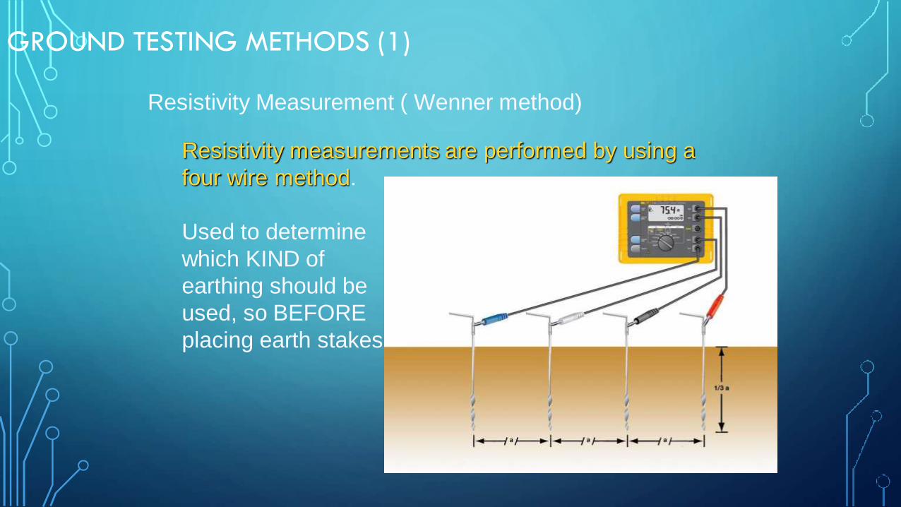
Resistivity Measurement ( Wenner method)
Resistivity measurements are performed by using a
four wire method.
Used to determine
which KIND of
earthing should be
used, so BEFORE
placing earth stakes
GROUND TESTING METHODS (1)

Resistivity Measurement
From the indicated resistance value RE, the soil
resistivity is calculated according to the equation :
E = 2 . a . RE
E ...... mean value of soil resistivity (W.m)
RE ...... measured resistance (W)
a ...... probe distance (m)
GROUND TESTING METHODS (1)

Curve 1: As E decreases only
deeper down, a deep earth
electrode is advisable
Curve 2: As E decreases only
down to point A, an increase in
the depth deeper than A does
not improve the values.
Curve 3: With increasing depth
E is not decreasing: a strip
conductor electrode is
advisable.
Resistivity Measurement
GROUND TESTING METHODS (1)
Related Documents