UNIT I - BASIC CONCEPTS OF MODELING 3 phase synchronous machine with and without damper bars and 3 - phase induction machine Introduction: It was shown in an earlier chapter that an alternator driven at a constant speed produces an alternating voltage at a fixed frequency dependent on the number of poles in the machine. A machine designed to be connected to the supply and run at synchronous speed is referred to as a synchronous machine. The description applies to both motors and generators. A synchronous condenser is a special application of a synchronous motor. While the synchronous motor has only one generally used name, the synchronous generator is on occasion referred to as an alternator or as an a.c. generator. The term alternator has been used in previous chapters and will be used in this chapter but it should be remembered that other terms are in use. In general, the principles of construction and operation are similar for both alternators and generators, just as there were basic similarities between d.c. motors and generators. While alternators were once seldom seen outside power houses and whole communities were supplied from a central source, there is now an expanding market for smaller sized alternators suitable for the provision of power for portable tools. Today, with the growth in computer control, there is a further need for standby generating plant to ensure a continuity of supply to prevent a loss of data from computer memories. So much information is being stored in computers today that even brief interruptions to the power supplies can have serious consequences on the accuracy and extent of information stored. Alternators The three-phase synchronous machine has two main windings: 1. a three-phase a.c. winding; 2. another winding carrying d.c. In the majority of cases, the rotor has the d.c. winding and the stator the a.c. winding. An alternator with a rotating a.c. winding and a stationary d.c. winding, while suitable for smaller outputs, is not satisfactory for the larger outputs required at power stations. With these machines the output can be in megawatts; a value too large to be handled with brushes and slip rings. Because the terminal voltages range up to 33 kV, the only satisfactory construction is to have the a.c. windings stationary and to supply the rotor with d.c. This arrangement has the following advantages: l. extra winding space for the a.c. windings; 2. easier to insulate for higher voltages; 3. simple, strong rotor construction; 4. lower voltages and currents in the rotating windings; 5. the high current \Vindings have solid connections to the "outside" circuit; 6. better suited to the higher speeds (and smaller number of poles) of turbine drives. Stator The stator of the three-phase synchronous machine consists of a slotted laminated core into which the stator winding is fitted. The stator winding consists of three separate windings physically displaced from each other by 120° E. Each phase winding has a number of coils connected in series to form a definite number of magnetic poles. A four-pole machine, for example, has four groups of coils per phase or four "pole-phase groups". The ends of the three phase windings are connected in either star or delta to the external circuit. Details of phase windings for a three-phase machine were shown in Chapter l 0 to consist of three identical windings symmetrically distributed around the stator. Prime movers Low speed Most diesel engines used as prime movers for alternators operate within the speed range of 50 r /min and this necessitates the use of rotors witl pairs of poles. Hydroelectric turbines have water-driven in which operate at low speeds, consequently they all rotors with. many poles. While the diesel-driven alt usually has its shaft in the horizontal plat hydroelectric unit has its shaft in the vertical plar method of construction means that special thrust t have to be fitted to take the end thrust of the 1 component.

Welcome message from author
This document is posted to help you gain knowledge. Please leave a comment to let me know what you think about it! Share it to your friends and learn new things together.
Transcript

UNIT I - BASIC CONCEPTS OF MODELING
3 phase synchronous machine with and without damper bars and 3 - phase induction machine
Introduction:
It was shown in an earlier chapter that an alternator driven at a constant speed produces an alternating voltage at a
fixed frequency dependent on the number of poles in the machine. A machine designed to be connected to the
supply and run at synchronous speed is referred to as a synchronous machine. The description applies to both
motors and generators. A synchronous condenser is a special application of a synchronous motor. While the
synchronous motor has only one generally used name, the synchronous generator is on occasion referred to as an
alternator or as an a.c. generator. The term alternator has been used in previous chapters and will be used in this
chapter but it should be remembered that other terms are in use. In general, the principles of construction and
operation are similar for both alternators and generators, just as there were basic similarities between d.c. motors
and generators. While alternators were once seldom seen outside power houses and whole communities were
supplied from a central source, there is now an expanding market for smaller sized alternators suitable for the
provision of power for portable tools. Today, with the growth in computer control, there is a further need for
standby generating plant to ensure a continuity of supply to prevent a loss of data from computer memories. So
much information is being stored in computers today that even brief interruptions to the power supplies can have
serious consequences on the accuracy and extent of information stored.
Alternators
The three-phase synchronous machine has two main windings:
1. a three-phase a.c. winding;
2. another winding carrying d.c.
In the majority of cases, the rotor has the d.c. winding and the stator the a.c. winding. An alternator with a rotating
a.c. winding and a stationary d.c. winding, while suitable for smaller outputs, is not satisfactory for the larger
outputs required at power stations. With these machines the output can be in megawatts; a value too large to be
handled with brushes and slip rings. Because the terminal voltages range up to 33 kV, the only satisfactory
construction is to have the a.c. windings stationary and to supply the rotor with d.c. This arrangement has the
following advantages: l. extra winding space for the a.c. windings; 2. easier to insulate for higher voltages; 3.
simple, strong rotor construction; 4. lower voltages and currents in the rotating windings; 5. the high current
\Vindings have solid connections to the "outside" circuit; 6. better suited to the higher speeds (and smaller number
of poles) of turbine drives.
Stator
The stator of the three-phase synchronous machine consists of a slotted laminated core into which the stator
winding is fitted. The stator winding consists of three separate windings physically displaced from each other by
120° E. Each phase winding has a number of coils connected in series to form a definite number of magnetic poles.
A four-pole machine, for example, has four groups of coils per phase or four "pole-phase groups". The ends of the
three phase windings are connected in either star or delta to the external circuit. Details of phase windings for a
three-phase machine were shown in Chapter l 0 to consist of three identical windings symmetrically distributed
around the stator.
Prime movers
Low speed
Most diesel engines used as prime movers for alternators operate within the speed range of 50 r /min and this
necessitates the use of rotors witl pairs of poles.
Hydroelectric turbines have water-driven in which operate at low speeds, consequently they all rotors with.
many poles. While the diesel-driven alt usually has its shaft in the horizontal plat hydroelectric unit has its shaft in
the vertical plar method of construction means that special thrust t have to be fitted to take the end thrust of the 1
component.

High speed
Turbine prime movers, whether steam or gas, efficiently at speeds in the vicinity of 3000 r / n alternator driven by a
turbine and producing a fn of 50 Hz at 3000 r /min must consist of only two In Chapter 6 the relationship between
frequency and the number of poles was shown tc
Synchronous motors
Principle of operation In order to understand the principle of operation of a synchronous motor, let us examine
what happens if we connect the armature winding (laid out in the stator) of a 3-phase synchronous machine to a
suitable balanced 3-phase source and the field winding to a D.C source of appropriate voltage. The current flowing
through the field coils will set up stationary magnetic poles of alternate North and South. ( for convenience let us
assume a salient pole rotor, as shown in Fig. 50). On the other hand, the 3-phase currents flowing in the armature
winding produce a rotating magnetic field rotating at synchronous speed. In other words there will be moving
North and South poles established in the stator due to the 3-phase currents i.e at any location in the stator there will
be a North pole at some instant of time and it will become a South pole after a time period corresponding to half a
cycle. (after a time = 1 2f , where f = frequency of the supply). Let us assume that the stationary South pole in the
rotor is aligned with the North pole in the stator moving in clockwise direction at a particular instant of time, as
shown in Fig. 50. These two poles get attracted and
try to maintain this alignment ( as per lenz’s law) and hence the rotor pole tries to follow the stator pole as the
conditions are suitable for the production of torque in the clockwise direction. However the rotor cannot move
instantaneously due to its mechanical inertia, and so it needs sometime to move. In the mean time, the stator pole
would quickly (a time duration corresponding to half a cycle) change its polarity and becomes a South pole. So the
force of attraction will no longer be present and instead the like poles experience a forceof repulsion as shown in
Fig. 51. In other words, the conditions are now suitable for the
Force of repulsion between stator poles and rotor poles - resulting in production of torque in anticlockwise
direction production of torque in the anticlockwise direction. Even this condition will not last longer as the stator
pole would again change to North pole after a time of 1 2f . Thus the rotor will experience an alternating force
which tries to move it clockwise and anticlockwise at twice the frequency of the supply, i.e. at intervals
corresponding to 1 2f seconds. As this duration is quite small compared to the mechanical time constant of the
rotor, the rotor cannot respond and move in any direction. The rotor continues to be stationary only. On the
contrary if the rotor is brought to near synchronous speed by some external means say a small motor (known as
pony motor-which could be a D.C or AC induction rotor) mounted on the same shaft as that of the rotor, the rotor
poles get locked to the unlike poles in the stator and the rotor continues to run at the synchronous speed even if the
supply to the pony motor is disconnected. Thus the synchronous rotor cannot start rotating on its own or usually we
say that the synchronous rotor has no starting torque. So, some special provision has to be made either inside the
machine or outside of the machine so that the rotor is brought to near about its synchronous speed. At that time, if
the armature is supplied with electrical power, the rotor can pull into step and continue to operate at its
synchronous speed. Some of the commonly used methods for starting synchronous rotor are described in the
following section.
Methods of starting synchronous motor
Basically there are three methods that are used to start a synchronous motor:
• To reduce the speed of the rotating magnetic field of the stator to a low enough value that the rotor can easily
accelerate and lock in with it during one half-cycle of the rotating magnetic field’s rotation. This is done by
reducing the frequency of the applied electric power. This method is usually followed in the case of inverter-fed
synchronous motor operating under variable speed drive applications.
• To use an external prime mover to accelerate the rotor of synchronous motor near to its synchronous speed and
then supply the rotor as well as stator. Ofcourse care should be taken to ensure that the direction of rotation of the
rotor as well as that of the rotating magnetic field of the stator are the same. This method is usually followed in the
laboratory- the synchronous machine is started as a generator and is then connected to the supply mains by
following the synchronization or paralleling procedure. Then the power supply to the prime mover is disconnected
so that the synchronous machine will continue to operate as a motor.
• To use damper windings or amortisseur windings if these are provided in the machine. The damper windings or
amortisseur windings are provided in most of the large synchronous motors in order to nullify the oscillations of
the rotor whenever the synchronous machine is subjected to a periodically varying load. Each of these methods of
starting a synchronous motor are described below in detail.
Behavior of a synchronous motor
The behavior of a synchronous motor can be predicted by considering its equivalent circuit on similar lines to that
of a synchronous generator as described below.
Equivalent circuit model and phasor diagram of a synchronous motor
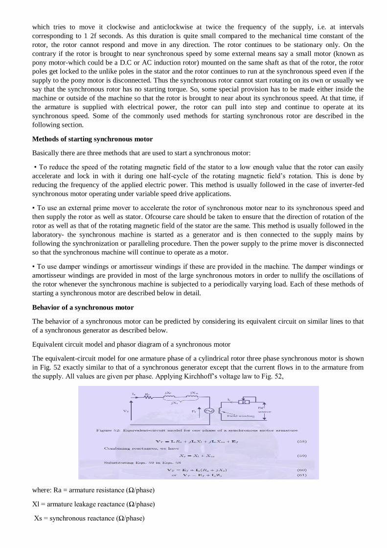
The equivalent-circuit model for one armature phase of a cylindrical rotor three phase synchronous motor is shown
in Fig. 52 exactly similar to that of a synchronous generator except that the current flows in to the armature from
the supply. All values are given per phase. Applying Kirchhoff’s voltage law to Fig. 52,
where: Ra = armature resistance (Ω/phase)
Xl = armature leakage reactance (Ω/phase)
Xs = synchronous reactance (Ω/phase)

Zs = synchronous impedance (Ω/phase)
VT = applied voltage/phase (V)
Ia = armature current/phase(A)
A phasor diagram shown in Fig. 53, illustrates the method of determining the counter EMF which is obtained from
the phasor equation;
Ef = VT − IaZs
The phase angle δ between the terminal voltage VT and the excitation voltage Ef in Fig. 53 is usually termed the
torque angle. The torque angle is also called the load angle or power angle.
UNIT II - REFERENCE FRAME THEORY
Transformation to obtain constant matrices:
Uses of Transformations
• Modeling transformations
– build complex models by positioning simple components
– transform from object coordinates to world coordinates
• Viewing transformations
– placing the virtual camera in the world
– i.e. specifying transformation from world coordinates to camera coordinates
• Animation
– vary transformations over time to create motion
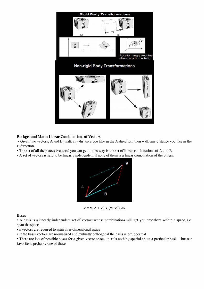
Background Math: Linear Combinations of Vectors
• Given two vectors, A and B, walk any distance you like in the A direction, then walk any distance you like in the
B direction
• The set of all the places (vectors) you can get to this way is the set of linear combinations of A and B.
• A set of vectors is said to be linearly independent if none of them is a linear combination of the others.
V = v1A + v2B, (v1,v2) • ƒ
Bases
• A basis is a linearly independent set of vectors whose combinations will get you anywhere within a space, i.e.
span the space
• n vectors are required to span an n-dimensional space
• If the basis vectors are normalized and mutually orthogonal the basis is orthonormal
• There are lots of possible bases for a given vector space; there’s nothing special about a particular basis—but our
favorite is probably one of these

Vectors Represented in a Basis
• Every vector has a unique representation in a given basis
–the multiples of the basis vectors are the vector’s components or coordinates
–changing the basis changes the components, but not the vector
–V = v1E1 + v2E2 + … vnEn The vectors E1 , E2 , …, En are the basis The scalars (v1 , v2 , …, vn ) are the
components of V with respect to that basis
Linear and Affine Maps
• A function (or map, or transformation) F is linear if for all vectors A and B, and all scalars k.
• Any linear map is completely specified by its effect on a set of basis vectors:
• A function F is affine if it is linear plus a translation
– Thus the 1-D transformation y=mx+b is not linear, but affine
– Similarly for a translation and rotation of a coordinate system
– Affine transformations preserve lines
F(A+B) = F(A) + F(B) F(kA) = k F
(A) V = v1E1 + v2E2 +v3E3
F(V) = F(v1E1 + v2E2 +v3E3) = F(v1E1) + F(v2E2) + F(v3E3) = v1F(E1) + v2F(E2) +v3F(E3)
Transforming a Vector
Matrices to the Rescue
An nxn matrix F represents a linear function in n dimensions
– i-th column shows what the function does to the corresponding basis vector
• Transformation = linear combination of columns of F – first component of the input vector scales first column of
the matrix – accumulate into output vector – repeat for each column and component
• Usually compute it a different way: – dot row i with input vector to get component i of output vector

Three Phase to Two Phase Transformation
This transformation could also be thought of as a transformation from three (abc) axes to three new (dqo)axes for
uniqueness of the transformation from one set of axes to another set of axes, including unbalances in the abc
variables requires three variables such as the dq0.[4]The reason for this is that it is easy to converter from three abc
variables to to qd variables if the abc variables have an inherent relationship among themselves, such as the equal
phase displacement and magnitude. Therefore, in such a case there are only two independent variables in a,b,c: the
third is a dependent variable obtained is unique under that circumstance This paper the variable s have no such
inherent relationship, then there are three distinct and independent variables: Hence the third variable cannot be
recovered from the knowledge of the other two variables only[5] .It is also mean that they are not recoverable from
two variables qd but require another variab bles only[5] .It is also mean that they are not recoverable from two
variables qd but require another variable such as the zero sequence component, to recover the[7] abc variables from
the variables.
THREE PHASE(a,b,c) to TWO PHASE(d,q,0)TRANSFORMATION
In electrical engineering, direct–quadrature–zero (abc) transformation or zero–direct–quadrature (dqo)
transformation is a mathematical transformation that rotates the reference frame of three-phase systems in an effort
to simplify the analysis of three-phase circuits. In the case of balanced three-phase circuits, application of the
dqo.transform reduces the three AC quantities to two DC quantities. Simplified calculations can then be carried out
on these DC quantities before performing the inverse transform to recover the actual three-phase AC results. It is
often used in order to simplify the analysis of three-phase synchronous machines or to simplify calculations for the
control of three-phase inverters. The power-invariant, right-handed dqo transform applied to any three-phase
quantities (e.g. voltages,
Geometric Interpretation
The dqo transformation is two sets of axis rotations in sequence. We can begin with a 3D space where a, b, and c
are orthogonal axes.
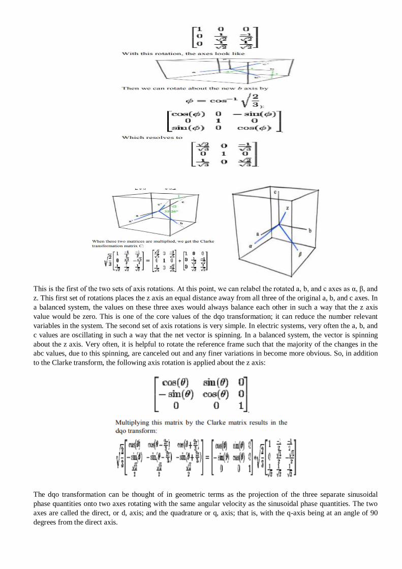
This is the first of the two sets of axis rotations. At this point, we can relabel the rotated a, b, and c axes as α, β, and
z. This first set of rotations places the z axis an equal distance away from all three of the original a, b, and c axes. In
a balanced system, the values on these three axes would always balance each other in such a way that the z axis
value would be zero. This is one of the core values of the dqo transformation; it can reduce the number relevant
variables in the system. The second set of axis rotations is very simple. In electric systems, very often the a, b, and
c values are oscillating in such a way that the net vector is spinning. In a balanced system, the vector is spinning
about the z axis. Very often, it is helpful to rotate the reference frame such that the majority of the changes in the
abc values, due to this spinning, are canceled out and any finer variations in become more obvious. So, in addition
to the Clarke transform, the following axis rotation is applied about the z axis:
The dqo transformation can be thought of in geometric terms as the projection of the three separate sinusoidal
phase quantities onto two axes rotating with the same angular velocity as the sinusoidal phase quantities. The two
axes are called the direct, or d, axis; and the quadrature or q, axis; that is, with the q-axis being at an angle of 90
degrees from the direct axis.

Shown above is the dqo transform as applied to the stator of a synchronous machine. There are three windings
separated by 120 physical degrees. The three phase currents are equal in magnitude and are separated from one
another by 120 electrical degrees. The three phase currents lag their corresponding phase voltages by . The d-q axis
is shown rotating with angular velocity equal to , the same angular velocity as the phase voltages and currents. The
d axis makes an angle with the A winding which has been chosen as the reference. The currents and are constant
DC quantities.
Power for equivalence
The power of a test estimates how likely it is that the test rejects the null hypothesis if the null hypothesis is indeed
false. Because the null hypothesis for an equivalence test is often the opposite from the null hypothesis of a
standard t-test of the population means, its power is expressed differently.
In equivalence testing, power is the likelihood that you will conclude that the population difference (or ratio) is
within your equivalence limits when it actually is. If your test has low power, you may mistakenly conclude that
you cannot claim equivalence when the difference (or ratio) is actually within the equivalence limits.
The following factors affect the power of your test.
Sample size
Larger samples give your test more power.
Difference
When the difference is close to the center of the two equivalence limits, your test has more power.
Standard deviation
Lower variability gives your test more power.
Alpha
Higher values for α give your test more power. However, α represents the probability of type I error. So
increasing α increases your chance of claiming equivalence when it is not true.
Use Power and Sample Size for 1-Sample Equivalence Test to examine the relationship between power, sample
size, and difference when you want to evaluate the equivalence between the mean of a product or process and a
target value.
Use these calculations for the following reasons:
Before you collect data for a 1-sample equivalence test, to ensure that your design has adequate sample size to
achieve acceptable power
After a 1-sample equivalence test, to improve the design for the next study
For example, a quality analyst wants to determine whether the mean force required to open snack bag seals is
within 10% of the target value of 4.2 N (Newtons). Before collecting the data for a 1-sample equivalence test, the
analyst uses a power and sample size calculation to determine how large the sample must be to obtain a power of
80% (0.8).
Use Power and Sample Size for 2-Sample Equivalence Test to examine the relationship between power, sample
size, and difference when you want to evaluate the equivalence between the test mean and the reference mean of
independent samples.
Use these calculations for the following reasons:
Before you collect data for a 2-sample equivalence test, to ensure that your design has an adequate sample size to
achieve acceptable power
After a 2-sample equivalence test, to improve the design for the next study
For example, a quality analyst wants to determine whether the mean amount of active ingredient in a generic brand
of pain reliever is within 1 mg of the mean amount in a popular brand of pain reliever. Before collecting the data
for a 2-sample equivalence test, the analyst uses a power and sample size calculation to determine how large the
sample size must be to obtain a power of 90% (0.9).
How are dependent and independent samples different?
Dependent samples are paired measurements for one set of items. Independent samples are measurements made on
two different sets of items.
When you conduct a hypothesis test using two random samples, you must choose the type of test based on whether
the samples are dependent or independent. Therefore, it's important to know whether your samples are dependent
or independent:
If the values in one sample affect the values in the other sample, then the samples are dependent.
If the values in one sample reveal no information about those of the other sample, then the samples are
independent.

Example of collecting dependent samples and independent samples
Consider a drug company that wants to test the effectiveness of a new drug in reducing blood pressure. They could
collect data in two ways:
Sample the blood pressures of the same people before and after they receive a dose. The two samples are dependent
because they are taken from the same people. The people with the highest blood pressure in the first sample will
likely have the highest blood pressure in the second sample.
Give one group of people an active drug and give a different group of people an inactive placebo, then compare the
blood pressures between the groups. These two samples would likely be independent because the measurements are
from different people. Knowing something about the distribution of values in the first sample doesn't inform you
about the distribution of values in the second.
Equivalence Test with Paired Data
Use Power and Sample Size for Equivalence Test with Paired Data to examine the relationship between power,
sample size, and difference when you want to evaluate the equivalence between a test mean and a reference mean
using paired observations.
Use these calculations for the following reasons:
Before you collect data for an equivalence test with paired data, to ensure that your design has an adequate sample
size to achieve acceptable power
After an equivalence test with paired data, to improve the design for the next study
The paired equivalence test is useful for analyzing a set of dependent observations, such as the same set of items
that were measured under two different conditions, or before-and-after measurements of the same person.
For example, an engineer for a vision care company wants to determine whether a new cleaning solution for
contact lenses is as effective as the leading brand. The engineer recruits 14 participants for the study. Each
participant will use a different cleaning solution on the contact lens in each eye. The engineer will measure the
residual film on each contact lens of each person, which will create paired observations. Before the engineer
collects the data for the equivalence test with paired data, she uses a power and sample size calculation to
determine whether a sample size of 14 provides adequate power for the test.
Electromagnetic torque
Milling is a machining process in which the piece material removal takes place intermittently. The milling
is accomplished by the combination of two movements performed simultaneously. One of the movements is
rotation of the cutter around its axis. The other is the movement of the milling machine table, which is attached to
the piece to be milled. Thus, cutting parameters such as feedrate, cutting speed and cutting depth should be
analyzed (Alves, 2002). According to Mao-Yue et al. (2009), parameters of the machining process should be
monitored and adjusted automatically, which can improve the production quality and reduce the machining time.
With advancements in applications using induction motors, the use of these motors on start and controlling of
positioning systems are majority in the industry. An example of positioner machine is the coordinate table, which
has applicability to devices milling, turning, drilling, and welding, among others.
The milling operation is one of the most important in the process of mechanical machining. The three-
phase induction motor is widely used in various applications in industry, due to its relative simplicity of
construction, maintenance, both operational and market low cost, as well as, the capacity to operate with a wide
range of loads in adverse conditions. One of the factors that provided the advancement in driving of three-phase
induction motor was the development of control strategies, specifically vector control strategies. In induction
machine, the implementation of vector control for field orientation can be done by direct or indirect method. The
direct field orientation enables the position of the flux is determined by measuring terminal quantities of the stator
(voltages and currents). The advantage of using the stator terminal quantities lies in the fact to be sensitive only to
the stator resistance (Altuna, 1997). In the development of controllers and estimators, and the use of vector control,
the application of intelligent control techniques, such as fuzzy logic and artificial neural network (ANN), provided
greater robustness to systems powered by three-phase induction motors. Fuzzy logic is a technique that allows the
implementation of human experience in systems, considering the uncertainty of information, the ambiguities, for
the development of controllers. The fuzzy inference model type TakagiSugeno (TS) is capable of representing,
approximately or exactly, any nonlinear dynamics as combination of locally valid linear models, interpolating
smoothly (Mozelli, 2008).
Torque equation
Whenever armature carries current in presence of flux, conductor experiences force which gives rise to the
electromagnetic torque. In this section we shall derive an expression for the electromagnetic torque Te developed in

a d.c machine. Obviously Te will be developed both in motor and generator mode of operation. It may be noted that
the direction of conductor currents reverses as we move from one pole to the other. This ensures unidirectional
torque to be produced. The derivation of the torque expression is shown below.
Thus we see that the above equation is once again applicable both for motor and generator mode of operation. The
direction of the electromagnetic torque, Te will be along the direction of rotation in case of motor operation and
opposite to the direction of rotation in case of generator operation. When the machine runs steadily at a constant
rpm then Te = Tload and Te = Tpm, respectively for motor and generator mode. The emf and torque equations are
extremely useful and should be remembered by heart.
Magnetic circuit network: (a) Flux flow; (b) Reluctance network; (c) Iron core calculations; (d) Airgap
calculations; (e) Algorithm used for calculations.
As the stator is excited with the power circuit the flux flow from the stator to the inner rotor yoke through air gap 2
(Rg2), enters the stator in the other face through air gap 3 (Rg3) in the bottom stator pole, moves to the outer yoke
through air gap 4 (Rg4) and returns to the excited coil through the airgap1 (Rg1) in the upper stator pole from the
outer rotor surface. The machine has two air gaps at the interaction teeth of the outer rotor-stator surface and the
inner rotor-stator surface on both sides of the flux flow (Rg1–Rg4). The magnetic circuit considered is long flux

flow and hence the reluctance
The flux tube path is chosen based on the position of the rotor with respect to the stator. Two flux tube paths are
assumed under unaligned and aligned position with the flux entering the upper part leaving the lower tube exactly
on the same side. At any partial aligned computation position the flux tube is assumed as three different paths with
flux lines flowing uniformly in the center tube and in the other two tubes the flux entering the upper surface leaves
on the opposite side of the lower surface. The surface area of flux linkage of the tubes depends on the rotor position
with respect to that of the stator surface at any time instance. Within the flux tube for each of the parts of the
machine such as the stator, rotor cores, air-gap etc., a small strip is integrated along the longitudinal axis and then
integrated over the surface under considerations from l1 to lm then from r1 to rn as in Figure 4c and Figure 4d for
the iron core and the air gap respectively. Figure 4e shows the algorithm used in the computation of the flux tube
analysis.
UNIT III - SMALL SIGNAL MODELING
• A small signal model is a linear model which is independent of amplitude. It may or may not have time
dependence (i.e. capacitors).
• The small signal model for a nonlinear component such as a BJT is a linear model about some nominal
operating point. The deviations from the operating point are small enough that it approximates the
nonlinear component over a limited range of amplitudes.
Small-signal modeling is a common analysis technique in electronics engineering which is used to
approximate the behavior of electronic circuits containing nonlinear devices with linear equations. It is applicable
to electronic circuits in which the AC signals, the time-varying currents and voltages in the circuit, have a small
magnitude compared to the DC biascurrents and voltages. A small-signal model is an AC equivalent circuit in which the nonlinear circuit elements are replaced by linear elements whose values are given by the first-order
(linear) approximation of their characteristic curve near the bias point.
The CMOS transistor is normally used as an amplifier when it is working in the saturation region (it has a low dependence with VDS and a high sensitivity to VGS). To characterize the transistor for that purpose, it is used
a model that considers that small signals are injected in the terminals of the transistor. That model linearizes
the ID−VGS and ID−VDScurves around a point of operation, called the bias or operating point.
The bias or operating point
Consider the following circuit:

A gate voltage vGS is applied to the transistor. A current will be generated that will match the current that flows through the resistance. This will in turn generate a voltage drop across the resistance and set the drain-source
voltage of the transistor. This will lead to a stable condition for the transistor, for which we call bias or operating
point.
The slider represents R. As you decrease R (go left), the current sunk by the transistor has a small voltage drop at
the resistance and the operating point goes to higher vDS. If you increase R (go right), the voltage drop is higher
and vDSdecreases. If the resistance was too large, it would put the transistor in triode region for this vGS.
R=1kΩ
Linearizing the curves
If a small signal vgs is superimposed on a DC signal VGS to produce vGS=VGS+vgs at the gate of the
transistor, the DC signal sets the bias and the small-signal will swing around that bias point. The curves around the
bias point are not linear and to get a simple model for small signals that can be analyzed, we approximate the
curves to lines to get a linear model.
The linear model is based on taking the derivatives of the drain current with respect to the voltages at the terminals
of the transistor.
The small-signal equivalent model
First let us find what components should make up this model. First we see that the transistor is a current
source controlled by the gate voltage, so a voltage-controlled current source should be there. Next, we see that the
current is also influenced by the drain-source voltage from the channel length modulation, which translates into an
output resistance. There is no input resistance because there is no current flowing through the gate.
Now it is time to determine the values of the transconductance gm and the output resistance ro.
Transconductance gm
gm is the change in current caused by a change in vGS, so it is:
gm=∂iD∂vGS.
The equation for gm depends whether the transistor is in triode or in saturation.
When in triode, gm does not really depend on vGS because iD is linear with vGS in this region.
However, vDS affects the transconductance linearly. When in saturation, gm depends on VGS and it is a parameter
that can be tweaked to control the gain of the transistor.

Output resistance ro
ro is the inverse of a change in current caused by a change in the drain-source voltage, so it is:
1/ro=go=∂iD∂vDS.
go is the output conductance and is commonly used in exchange of ro when it simplifies the equations. The
equation for godepends whether the transistor is in triode or in saturation.
From here we see that the transistor is not a very good amplifier in the triode region, because its gain is changed
with the output voltage and we can only play with the transistor's size to control the gain. It is not a very good
current source either, because its gain (and therefore its current) and its output resistance changes with the output
voltage. The transistor is usually used in the saturation region for amplification. Also, to reduce the distortion
caused by the amplification, the bias point should be somewhere in the middle of the saturation region, so that large
swings of the drain voltage will not bring the transistor into the triode region or saturate to the power supply
voltage.
Include body effect
The body effect changes the threshold voltage, which in turn affects the drain current. How can this be incorporated
in the model? The body is like another gate (it is sometimes called a back-gate) and it is modelled as just that:
Since vBS is always negative, the current direction of the gmb current source is actually the opposite of
the gm current source. To calculate the value of gmb, we have to realize that there is a cascade of effects
(vBS to VTH and VTH to iD):
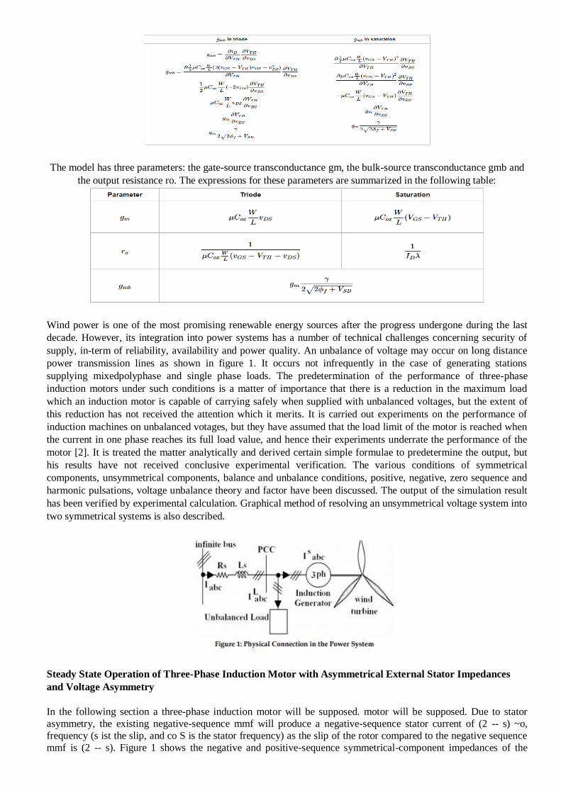
The model has three parameters: the gate-source transconductance gm, the bulk-source transconductance gmb and
the output resistance ro. The expressions for these parameters are summarized in the following table:
Wind power is one of the most promising renewable energy sources after the progress undergone during the last
decade. However, its integration into power systems has a number of technical challenges concerning security of
supply, in-term of reliability, availability and power quality. An unbalance of voltage may occur on long distance
power transmission lines as shown in figure 1. It occurs not infrequently in the case of generating stations
supplying mixedpolyphase and single phase loads. The predetermination of the performance of three-phase
induction motors under such conditions is a matter of importance that there is a reduction in the maximum load
which an induction motor is capable of carrying safely when supplied with unbalanced voltages, but the extent of
this reduction has not received the attention which it merits. It is carried out experiments on the performance of
induction machines on unbalanced votages, but they have assumed that the load limit of the motor is reached when
the current in one phase reaches its full load value, and hence their experiments underrate the performance of the
motor [2]. It is treated the matter analytically and derived certain simple formulae to predetermine the output, but
his results have not received conclusive experimental verification. The various conditions of symmetrical
components, unsymmetrical components, balance and unbalance conditions, positive, negative, zero sequence and
harmonic pulsations, voltage unbalance theory and factor have been discussed. The output of the simulation result
has been verified by experimental calculation. Graphical method of resolving an unsymmetrical voltage system into
two symmetrical systems is also described.
Steady State Operation of Three-Phase Induction Motor with Asymmetrical External Stator Impedances
and Voltage Asymmetry
In the following section a three-phase induction motor will be supposed. motor will be supposed. Due to stator
asymmetry, the existing negative-sequence mmf will produce a negative-sequence stator current of (2 -- s) ~o,
frequency (s ist the slip, and co S is the stator frequency) as the slip of the rotor compared to the negative sequence
mmf is (2 -- s). Figure 1 shows the negative and positive-sequence symmetrical-component impedances of the
machine; the same assumptions are made as in [10], however the rotor is symmetrical now, As the negative-sequence impedance is smaller than the impedance of the symmetrical machine, it can be seen that in case of
relatively small asymmetries, negative sequence currents of large values can occur. The effect of asymmetry is the
smallest in the case of standstill, and is the greatest around synchroArchiv ffir Elektrotechnik 59 (1977) nous speed.
Therefore, due to asymmetry, at least one of the stator phase currents is greater than for a symmetrical machine, which results in higher loads and heatings of the stator windings. Besides the increase of the stator current, other
undesirable effects will also occur, such as the reduction of the mechanical power, as the motor tends to revolve in
the backward direction due to the negative sequence mmf. As a consequence, the negative sequence torque -- which exists because of the asymmetry -- could reduce the positive sequence torque. Also the pulsating torques can
cause undesirable effects, too. In deriving the total equivalent circuit for the steady state operation of the
asymmetrical machine the method presented in [lO 1 will be followed. Anyhow, for an asymmetrical machine two main groups of calculation methods can be utilized. The first group consists of those methods, where the
phasecoordinate equations of the asymmetrical machine are directly solved. In case of the second group, the phase-
coordinate equations are simplified by transformations -- and in some cases by partitions too -- and the simplified
equations are solved. (Sometimes transformations are even used if they do not lead to simpler equations, but the physical phenomena become clearer.) If it is the purpose only to derive the results, a method of the first group must
be used, e.g. in transient operation, the first order differential equations are solved by a digital computer. In this
case the additive components due to asymmetry will be separately not present, although they can be calculated by using the conditions of the symmetrical machine too. In steady-state operation, first the voltage equations must be
solved for the currents if a method of the first group is used. This can be also accomplished by the direct inversion
of the impedance matrix; however, if partitioning is also possible, it is useful to carry out this simplification, too. However, if the additive components are neceessary to be in an anlytical form, two methods can be followed. In
case of partially asymmetrical machines, dyadic methods can be used; or by using the initial conditions of
symmetrical and asymmetrical machine, the differential component will be equal to the additive one. In the
followings a method of the second group will be used as the physical phenomena become clear th:,s way. The external impedances of the stator are Z a, Zb, and Z c respectively, the stator is star connected. The symmetrical
components of the stator votages are Us~ Us1, and Us~, and the symmetrical component equation is
Single-Phase Motors
Single phase motors are the most familiar of all electric motors because they are extensively used in home appliances, shops, offices etc. It is true that single phase motors are less efficient substitute for 3-phase motors but
3-phase power is normally not available except in large commercial and industrial establishments. Since electric
power was originally generated and distributed for lighting only, millions of homes were given single-phase
supply. This led to the development of single-phase motors. Even where 3-phase mains are present, the single-phase supply may be obtained by using one of the three lines and the neutral. Single-phase induction motors are
usually two-pole or four-pole, rated at 2 hp or less, while slower and larger motor can be manufactured for special
purposes. They are widely used in domestic appliances and for a very large number of low power drives in industry. The single phase induction motor resembles, three-phase, squirrel-cage motor except that, single phase
induction motor has no starting torque and some special arrangement have to be made to make it as self starting. In
this chapter, we shall focus our attention on the construction, working and characteristics of commonly used single-phase motors.
Types of Single-Phase Motors:
Single-phase motors are generally built in the fractional-horsepower range and may be classified into the
following four basic types:
1. Single-phase induction motors
(i) split-phase type
(ii) capacitor start type
(iii) capacitor start capacitor run type (v) shaded-pole type
2. A.C. series motor or universal motor
3. Repulsion motors (i) Repulsion-start induction-run motor
(ii) Repulsion-induction motor

4. Synchronous motors (i) Reluctance motor
(ii) Hysteresis motor
Single-Phase Induction Motors
A single phase induction motor is very similar to a 3-phase squirrel cage induction motor. Unlike a 3-phase induction motor, a single-phase induction motor is not self starting but requires some starting means. The single-
phase stator winding produces a magnetic field that pulsates in strength in a sinusoidal manner. The field polarity
reverses after each half cycle but the field does not rotate. Consequently, the alternating flux cannot produce rotation in a stationary squirrel-cage rotor. However, if the rotor of a single-phase motor is rotated in one direction
by some mechanical means, it will continue to run in the direction of rotation. As a matter of fact, the rotor quickly
accelerates until it reaches a speed slightly below the synchronous speed. Once the motor is running at this speed, it will continue to rotate even though singlephase current is flowing through the stator winding. This method of
starting is generally not convenient for large motors. Figure 7.2 shows picture of single phase induction motor.
Construction of single phase induction motor
The construction parts on of single phase induction motor consist of main two parts: stationary stator and revolving
rotor. The stator separate from rotor by small air gap have ranges from 0.4 mm to 4 mm depends to size of motor.
Stator
The single-phase motor stator has a laminated iron core with two windings arranged perpendicularly, One is the
main and the other is the auxiliary winding or starting winding as showing in the figure 7.2. It consists of a steel frame which encloses a hollow, cylindrical core made up of thin laminations of silicon steel to reduce hysteresis
and eddy current losses. A number of evenly spaced slots are provided on the inner periphery of the laminations.
Rotor
The rotor, mounted on a shaft, is a hollow laminated core having slots on its outer periphery. The winding placed in these slots (called rotor winding) may be one of the following two types:
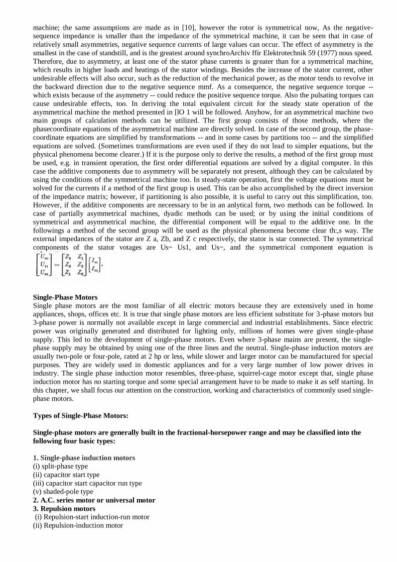
(i) Squirrel cage rotor:
It consists of a laminated cylindrical core having parallel slots on its outer periphery. One copper or aluminum bar is placed in each slot. All these bars are joined at each end by metal rings called end rings [See Fig. 7.3]. This
forms a permanently shortcircuited winding which is indestructible. The entire construction (bars and end rings)
resembles a squirrel cage and hence the name. The rotor is not connected electrically to the supply but has current
induced in it by transformer action from the stator. Those induction motors which employ squirrel cage rotor are called squirrel cage induction motors. Most of single phase induction motors use squirrel cage rotor as it has a
remarkably simple and robust construction enabling it to operate in the most adverse circumstances. However, it
suffers from the disadvantage of a low starting torque. because the rotor bars are permanently short-circuited and it is not possible to add any external resistance to the rotor circuit to have a large starting torque. In this type of rotor
the bars conductor are skew to reduce the noise.
Wound rotor:
It consists of a laminated cylindrical core and carries a single phase winding, similar to the one on the stator. The open ends of the rotor winding are brought out and joined to three insulated slip rings mounted on the rotor shaft
with one brush resting on each slip ring. The two brushes are connected to a single phase star-connected rheostat as
shown in Figure 7.4. At starting, the external resistances are included in the rotor circuit to give a large starting torque. These resistances are gradually reduced to zero as the motor runs up to speed. The external resistances are
used during starting period only. When the motor attains normal speed, the two brushes are short-circuited so that
the wound rotor runs like a squirrel cage rotor.
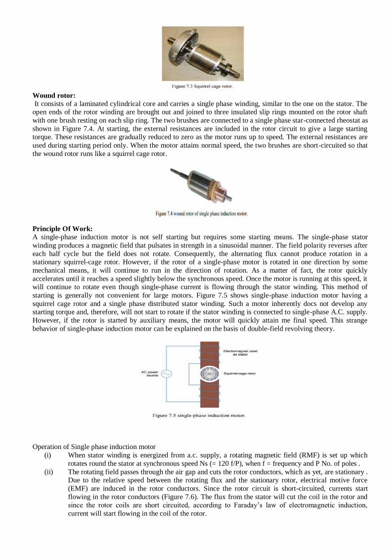
Principle Of Work:
A single-phase induction motor is not self starting but requires some starting means. The single-phase stator
winding produces a magnetic field that pulsates in strength in a sinusoidal manner. The field polarity reverses after
each half cycle but the field does not rotate. Consequently, the alternating flux cannot produce rotation in a stationary squirrel-cage rotor. However, if the rotor of a single-phase motor is rotated in one direction by some
mechanical means, it will continue to run in the direction of rotation. As a matter of fact, the rotor quickly
accelerates until it reaches a speed slightly below the synchronous speed. Once the motor is running at this speed, it will continue to rotate even though single-phase current is flowing through the stator winding. This method of
starting is generally not convenient for large motors. Figure 7.5 shows single-phase induction motor having a
squirrel cage rotor and a single phase distributed stator winding. Such a motor inherently docs not develop any starting torque and, therefore, will not start to rotate if the stator winding is connected to single-phase A.C. supply.
However, if the rotor is started by auxiliary means, the motor will quickly attain me final speed. This strange
behavior of single-phase induction motor can be explained on the basis of double-field revolving theory.
Operation of Single phase induction motor
(i) When stator winding is energized from a.c. supply, a rotating magnetic field (RMF) is set up which
rotates round the stator at synchronous speed Ns (= 120 f/P), when f = frequency and P No. of poles .
(ii) The rotating field passes through the air gap and cuts the rotor conductors, which as yet, are stationary . Due to the relative speed between the rotating flux and the stationary rotor, electrical motive force
(EMF) are induced in the rotor conductors. Since the rotor circuit is short-circuited, currents start
flowing in the rotor conductors (Figure 7.6). The flux from the stator will cut the coil in the rotor and since the rotor coils are short circuited, according to Faraday’s law of electromagnetic induction,
current will start flowing in the coil of the rotor.

(iii) (iii) The current-carrying rotor conductors are placed in the magnetic field produced by the stator. Consequently, mechanical force acts on the rotor conductors. The sum of the mechanical forces on all
the rotor conductors produces a torque which tends to move the rotor in the same direction as the
rotating field with speed N =Ns (1-S) when S= slip and N = rotor speed (Figure 7.6).
Cross-field theory:
The principle of operation of a single-phase induction motor can be explained from the cross-field theory. As soon
as the rotor begins to turn, a speed emf E is induced in the rotor conductors, as they cut the stator flux Fs. This
voltage increases as the rotor speed increases. It causes current Ir to flow in the rotor bars facing the stator poles as shown in figure 7.7 . These currents produce an ac flux FR which act at right angle to the stator flux Fs. Equally
important is the fact that FR does not reach its maximum value at the same time as FS does, in effect, FR lags
almost 90o behind FS, owing to the inductance of the rotor The combined action of Fs and FR produces a revolving magnetic field, similar to that in a three-phase motor. The value of FR increases with increasing speed,
becoming almost equal to Fs at synchronous speed. The flux rotates counterclockwise in the same direction as the
rotor and it rotates at synchronous speed irrespective of the actual speed of the rotor. As the motor approaches
synchronous speed, FR becomes almost equal to Fs and a nearly perfect revolving field is produces.
Double-field revolving theory: When the stator winding (distributed one as stated earlier) carries a sinusoidal current (being fed from a single-
phase supply), a sinusoidal space distributed mmf, whose peak or maximum value pulsates (alternates) with time,
is produced in the air gap. This sinusoidal varying flux (φ ) is the sum of two rotating fluxes or fields, the
magnitude of which is equal to half the value of the alternating flux (φ / 2), and both the fluxes rotating synchronously at the speed, in opposite directions. The first set of figures (Figure 7.8a (i-iv)) show the resultant
sum of the two rotating fluxes or fields, as the time axis (angle) is changing from θ = 0° to π °(180) . Figure 7.8b
shows the alternating or pulsating flux (resultant) varying with time or angle.
The flux or field rotating at synchronous speed, say, in the anticlockwise direction, i.e. the same direction, as that of the motor (rotor) taken as positive induces EMF (voltage) in the rotor conductors. The rotor is a squirrel cage one,
with bars short circuited via end rings. The current flows in the rotor conductors, and the electromagnetic torque is
produced in the same direction as given above, which is termed as positive (+ve). The other part of flux or field
rotates at the same speed in the opposite (clockwise) direction, taken as negative. So, the torque produced by this field is negative (-ve), as it is in the clockwise direction, same as that of the direction of rotation of this field. Two
torques are in the opposite direction, and the resultant (total) torque is the difference of the two torques produced.
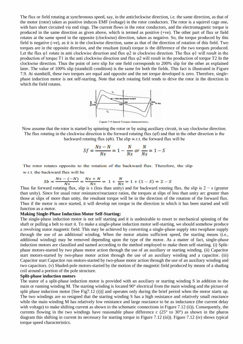
Let the flux φ1 rotate in anti clockwise direction and flux φ2 in clockwise direction. The flux φ1 will result in the production of torque T1 in the anti clockwise direction and flux φ2 will result in the production of torque T2 In the
clockwise direction. Thus the point of zero slip for one field corresponds to 200% slip for the other as explained
later. The value of 100% slip (standstill condition) is the same for both the fields. This fact is illustrated in Figure 7.9. At standstill, these two torques are equal and opposite and the net torque developed is zero. Therefore, single-
phase induction motor is not self-starting. Note that each rotating field tends to drive the rotor in the direction in
which the field rotates.
Now assume that the rotor is started by spinning the rotor or by using auxiliary circuit, in say clockwise direction. The flux rotating in the clockwise direction is the forward rotating flux (φf) and that in the other direction is the
backward rotating flux (φb). The slip w.r.t. the forward flux will be
Thus fur forward rotating flux, slip is s (less than unity) and for backward rotating flux, the slip is 2 − s (greater than unity). Since for usual rotor resistance/reactance ratios, the torques at slips of less than unity arc greater than
those at slips of more than unity, the resultant torque will be in the direction of the rotation of the forward flux.
Thus if the motor is once started, it will develop net torque in the direction in which it has been started and will function as a motor.
Making Single-Phase Induction Motor Self-Starting:
The single-phase induction motor is not self starting and it is undesirable to resort to mechanical spinning of the shaft or pulling a belt to start it. To make a single-phase induction motor self-starting, we should somehow produce
a revolving stator magnetic field. This may be achieved by converting a single-phase supply into twophase supply
through the use of an additional winding. When the motor attains sufficient speed, the starting means (i.e.,
additional winding) may be removed depending upon the type of the motor. As a matter of fact, single-phase induction motors are classified and named according to the method employed to make them self-starting. (i) Split-
phase motors-started by two phase motor action through the use of an auxiliary or starting winding. (ii) Capacitor
start motors-started by two-phase motor action through the use of an auxiliary winding and a capacitor. (iii) Capacitor start Capacitor run motors-started by two-phase motor action through the use of an auxiliary winding and
two capacitors. (v) Shaded-pole motors-started by the motion of the magnetic field produced by means of a shading
coil around a portion of the pole structure.
Split-phase induction motors The stator of a split-phase induction motor is provided with an auxiliary or starting winding S in addition to the
main or running winding M. The starting winding is located 90° electrical from the main winding and the picture of
split phase induction motor [See Fig7.12 (i))] and operates only during the brief period when the motor starts up. The two windings are so resigned that the starting winding S has a high resistance and relatively small reactance
while the main winding M has relatively low resistance and large reactance to be as inductance (the current delay
with voltage) to make shifting current as shown in the schematic connections in Figure 7.12 (ii)). Consequently, the currents flowing in the two windings have reasonable phase difference c (25° to 30°) as shown in the pharos
diagram this shifting in current its necessary for starting torque in Figure 7.12 (iii)). Figure 7.12 (iv) shows typical
torque speed characteristics.

UNIT IV - MODELING OF SYNCHRONOUS MACHINE
SYNCHRONOUS MACHINE INDUCTANCES:
The schematic diagram of a synchronous generator is shown in Fig. 1.15. This contains three stator windings that
are spatially distributed. It is assumed that the windings are wye-connected. The winding currents are denoted
by ia , ib and ic. The rotor contains the field winding the current through which is denoted by if . The field winding is
aligned with the so-called direct ( d ) axis. We also define a quadrature ( q ) axis that leads the d -axis by 90°. The
angle between the d-axis and the a-phase of the stator winding is denoted by θd.

Torque Equation of an Induction Motor
The developed Torque or Induced Torque Equation in a machine is defined as the Torque generated by the
electric to mechanical power conversion. The torque is also known as Electromagnetic Torque. This developed
torque in the motor differs from the actual torque available at the terminals of the motor, which is almost equal to
the friction and windage torques on the machine.
The developed torque equation is given as
The above equation expresses the developed torque directly in terms of the air gap power Pg and the synchronous
speed ωs. Since ωs is constant and independent of the load conditions. If the value of the Pg is known then, the
developed torque can be found directly. The air gap power Pg is also called as the Torque in Synchronous Watts.
Synchronous Watt is the torque that develops the power of 1 Watt when the machine is running at synchronous
speed.
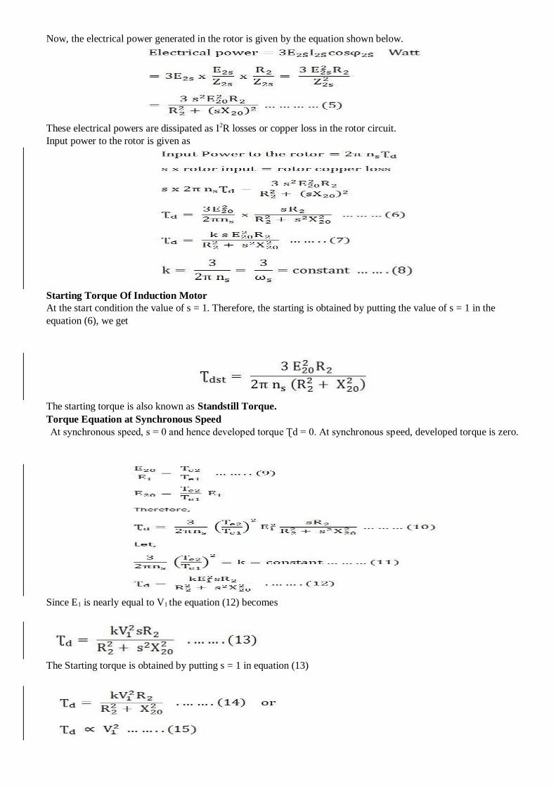
Now, the electrical power generated in the rotor is given by the equation shown below.
These electrical powers are dissipated as I2R losses or copper loss in the rotor circuit.
Input power to the rotor is given as
Starting Torque Of Induction Motor
At the start condition the value of s = 1. Therefore, the starting is obtained by putting the value of s = 1 in the
equation (6), we get
The starting torque is also known as Standstill Torque.
Torque Equation at Synchronous Speed
At synchronous speed, s = 0 and hence developed torque Ʈd = 0. At synchronous speed, developed torque is zero.
Since E1 is nearly equal to V1 the equation (12) becomes
The Starting torque is obtained by putting s = 1 in equation (13)

Hence, it is clear from the above equation that the starting torque is proportional to the square of the stator applied
voltage.
Current in terms of flux linkages:
What is meant by flux linkage?
In this case the flux linkage is simply the flux density passing through the loop multiplied by its surface area; i.e., .
If several turns of the wire are made, this becomes where N is the number of turns. In this case, the surface through
which the magnetic flux is passing has been increased by a factor.
Flux linkage is a property of a two-terminal element. Although it is often confused with magnetic flux, the flux
linkage is actually an extension rather than an equivalent of magnetic flux. Flux linkage is defined as
where is the voltage across the device or the potential difference between the two terminals. This definition
can also be written in differential form as
Faraday showed that the magnitude of the EMF generated in a conductor forming a closed loop is proportional to
the rate of change of the total magnetic flux passing through the loop (Faraday's law). Thus, for a typical
inductance (a coil of conducting wire), the flux linkage is equivalent to magnetic flux, which is the total magnetic
field passing through the surface (i.e., normal to that surface) formed by a closed conducting loop coil, and is
determined by the number of turns in the coil and the magnetic field; i.e.,
where is the flux density, or flux per unit area at a given point in space.
The simplest example of such a system is a single circular coil of conductive wire immersed in a magnetic field, in
which case the flux linkage is simply the flux passing through the loop.
n order to understand the distinction in terms, it is important to note that the flux through the surface
delimited by a coil turn exists independently of the presence of the coil. Furthermore, in a thought experiment with
a coil of turns, where each turn forms a loop with exactly the same boundary, each turn will "link" the "same"
(identically, not merely the same quantity) flux , all for a total flux linkage of . The distinction relies
heavily on intuition, and the term "flux linkage" is used mainly in engineering disciplines. Theoretically, the case
of a multi-turn induction coil is explained and treated perfectly rigorously with Riemann surfaces: what is called
"flux linkage" in engineering is simply the flux passing through the Riemann surface bounded by the coil's turns,
hence no particularly useful distinction between flux and "linkage."
Due to the equivalence of flux linkage and total magnetic flux in the case of inductance, it is popularly
accepted that the flux linkage is simply an alternative term for total flux, used for convenience in engineering
applications. Nevertheless, this is not true, especially for the case of memristor, which is also referred to as the
fourth fundamental circuit element. For a memristor, the electric field in the element is not as negligible as for the
case of inductance, so the flux linkage is no longer equivalent to magnetic flux. In addition, for a memristor, the
flux linkage related energy is dissipated in the form of Joule heating, instead of being stored in magnetic field as
done in the case of an inductance: there is no physical magnetic field involved as a link to anything! In conclusion,
flux linkage should be interpreted as an extension rather than an equivalent to magnetic flux.
Flux linkage is commonly used to estimate the magnetic flux of an AC motor. However, errors in the
voltage measurement and the resulting drift problem of the integral cause the ideal integral to often be replaced
with a low-pass filter approximation.

SIMULATION OF THREE PHASE SYNCHRONOUS MACHINE
Description
A three-phase generator rated 200 MVA, 13.8 kV, 112.5 rpm is connected to a 230 kV, 10,000 MVA network
through a Delta-Wye 210 MVA transformer. At t = 0.1 s, a three-phase to ground fault occurs on the 230 kV bus.
The fault is cleared after 6 cycles (t = 0.2 s)
Simulation
1. Open the Powergui and select 'Machine Initialization'. A new window appears. The machine 'Bus type' is
initialized as 'PV generator', indicating that the initialization is performed with the machine controlling the active
power and its terminal voltage. The desired terminal voltage parameter is set to 13800 and the active Power to
150e6.*
Press the 'Compute and Apply' button. The phasors of AB and BC machine voltages as well as the currents flowing
out of phases A and B are updated. The machine reactive power, mechanical power and field voltage requested to
supply the electrical power is also be displayed: Q = 3.4 Mvar; Pmec = 150.32 MW (0.7516 pu); field voltage Ef =
1.291 pu.
2. In order to start the simulation in steady state with the HTG and excitation system connected, these two blocks
are initialized according to the values calculated by the Machine Initialization tool. This initialization is
automatically performed as long as you connect at the Pm and Vf inputs of the machine either Constant blocks or
regulation blocks from the machine library (HTG, STG, or Excitation System). Open the HTG block menu and
note that the initial mechanical power was set to 0.7516 pu (150.32 MW) by the tool. Open the Excitation System
block menu and note that the initial terminal voltage and field voltage have been set respectively to 1.0 and 1.29071
pu.
3. Open the 4 scopes and restart the simulation. Observe that the terminal voltage Va is 1.0 p.u. at the beginning of
the simulation. It falls to about 0.4 pu during the fault and returns to nominal quickly after the fault is cleared. This
quick response in terminal voltage is due to the fact that the Excitation System output Vf can go as high as 11.5 pu
which it does during the fault. The speed of the machine increases to 1.01 pu during the fault then it oscillates
around 1 p.u. as the governor system regulates it. The speed takes much longer than the terminal voltage to
stabilize mainly because the rate of valve opening/closing in the governor system is limited to 0.1 pu/s.
MODELING OF PM SYNCHRONOUS MOTOR
Introduction
PM synchronous motors are now very popular in a wide variety of industrial applications. A large majority of
them are constructed with the permanent magnets mounted on the periphery of the rotor core. Following [1], we
will call them as the Surface Permanent Magnet (SPM) synchronous motors. When permanent magnets are buried
inside the rotor core rather than bonded on the rotor surface, the motor not only provides mechanical ruggedness
but also opens a possibility of increasing its torque capability. By designing a rotor magnetic circuit such that the
inductance varies as a function of rotor angle, the reluctance torque can be produced in addition to the mutual
reaction torque of synchronous motors. This class of Interior PM (IPM) synchronous motors can be considered as
the reluctance synchronous motor and the PM synchronous motor combined in one unit. It is now very popular in
industrial and military applications by providing high power density and high efficiency compared to other types of
motors. Conventionally, a 2-phase equivalent circuit model (d-q model) [2] has been used to analyze reluctance
synchronous machines. The theory is now applied in analysis of other types of motors [3-7] including PM
synchronous motors, induction motors etc. In Section II, an equivalent 2-phase circuit model of a 3-phase IPM
machines is derived in order to clarify the concept of the transformation and the relation between 3-phase quantities
and their equivalent 2-phase quantities. Although the above equivalent circuit is very popular, discussions on
obtaining parameters of the equivalent circuit for a given motor are rarely found. The main objective of the article
is to establish a method to obtain 2-phase circuit parameters from physically measured data. Throughout the article,
the following assumptions are made: (1) Stator windings produce sinusoidal mmf distribution. Space harmonics in
the air-gaps are neglected. (2) Air-gap reluctance has a constant component as well as a sinusoidally varying
component. (3) Balanced 3 phase supply voltage is considered. (4) Although magnetic saturation is considered,
eddy current and hysteresis effects are neglected. In addition, presence of damper windings are not considered here
because they are not used in PM synchronous machines in general.
Characterization Of Model Parameters

UNIT V - DYNAMIC ANALYSIS OF SYNCHRONOUS MACHINE
Dynamic performance of synchronous machine:
AC permanent magnet (PM) motors work as synchronous and brushless DC motors, the motor consists of a
wound stator and a rotor. The stator may have a single-phase or multi-phase winding which is sometimes called the
armature winding [1] (see Fig. 1). The rotor has a permanent magnet.
Since there is no winding in the rotor (that would be supplied through the brushes), the AC PM machines
are also called brushless PM machines. The rotor of the AC PM motor rotates synchronously with the magnetic
field generated by the stator winding. The AC PM motor when operating in each of the above modes, i.e.
synchronous or brushless DC motor, performs differently. Thus, its electromechanical characteristics will differ
significantly. Especially when these modes of PM motor fed single phase source instead of three phase source. The
BLDC motors are available in many different power rating from very small motors as used in hard disk drives to
large motor used in electrical vehicles. Three phase motors are most common but two phase motors are also
available in many applications. In the reference, the simulation of dynamic state of BLCD motor was presented and
the result shown that the torque ripples in three phase system is less when compared to that of two-phase system.
Equal area criteria
The stability studies which evaluate the impact of disturbances on the behavior of synchronous machines
of the power system are of two types: transient stability and steady state stability.

The transient stability studies involve the determination of whether or not synchronism is maintained after
the machine has been subjected to a severe disturbance. This may be a sudden application of large load, a loss of
generation, a loss of large load, or a fault (short circuit) on the system. In most disturbances, oscillations are such
magnitude that linearization is not permissible and nonlinear equations must be solved to determine the stability of
the system.
The steady-state stability is concerned with the system subjected to small disturbances wherein the stability
analysis could be done using the linearized version of nonlinear equations. In this experiment we are concerned
with the transient stability of power systems.
In a two-machine system, under the usual assumptions of constant input, and constant voltage behind
transient reactance, the angle between the machines either increases indefinitely or else, after all disturbances have
occurred, oscillates with constant amplitude. In other words the two machines either fall out of step on first swing
or never. Under these conditions the observation that the machines come to rest with respect top each other may be
taken as the proof that the system is stable. There is a simple graphical method of determining whether the
machines come to rest with respect to each other. This method is known as the equal area criterion of stability.
When the fault occurs at t=0, the electrical power output is suddenly zero while pm is unaltered. The
difference in power must be accounted for by a rate of change of store kinetic energy in the rotor masses. This is
accomplished only by an increase in speed which results from the constant accelerating power pm.
After reaching δ2, δ(t) will oscillate until losses and the load damp oscillations and δ(t) = δ0
If δ2 > δ3 the generator looses stability because pe < pm and the generator continues to accelerate.
Related Documents