December 2014 The Activity: In this task the students investigate the functions and operations of a D Type flip-flop featuring a set of tasks. Suggested timings: 2 hours Unit 4: Principles of Electrical and Electronic Engineering LO6: Understand digital electronics – D type bistable flip-flop Instructions and answers for teachers These instructions should accompany the OCR resource ‘Understand digital electronics – D type bistable flip-flop’ activity which supports Cambridge Technicals in Engineering Level 3. This activity offers an opportunity for maths skills development. This activity offers an opportunity for English skills development.

Welcome message from author
This document is posted to help you gain knowledge. Please leave a comment to let me know what you think about it! Share it to your friends and learn new things together.
Transcript

December 2014
The Activity: In this task the students investigate the functions and operations of a D Type flip-flop featuring a set of tasks.
Suggested timings:
2 hours
Unit 4: Principles of Electrical and Electronic Engineering
LO6: Understand digital electronics – D type bistable flip-flop
Instructions and answers for teachers These instructions should accompany the OCR resource ‘Understand digital electronics – D type bistable flip-flop’ activity which supports Cambridge Technicals in Engineering Level 3.
This activity offers an
opportunity for maths
skills development.
This activity offers an
opportunity for English
skills development.

December 2014
Activity 1 In Activity 1, learners are tasked to investigate the function and operation of the D type flip-flop and to
consider:
• How does the flip-flop operate and what is its purpose? • What are each of the inputs and outputs? • In what type of applications are flip-flops used?
D Q
Q
CK
Solutions
• The D type flip-flop is a latching device with outputs that have two stable states. This means that the output can be switched from logic 0 to logic 1, or logic 1 to logic 0 when required. Once set into either of these states, it will remain there indefinitely so long as power is maintained to the device. For this reason it is often termed a ‘bistable’.
• The purpose of a D type flip-flop is to act as a ‘latch’ or memory/ storage device. It can store the information present on its inputs.
• The terminals are as follows:
D The terminal labelled D is called the data input terminal and is
where the flip-flop receives data.
CK CK is the clock input. When a logic 1 is applied to the terminal,
whatever signal is on the D terminal (0 or 1) is transferred to the Q
terminal. For the device shown, this is usually referred to as rising
edge triggered.
Q Q is the output terminal.
Q Q bar or NOT Q is another output terminal, which is the inverse of
Q.
• Typical applications of the D type flip-flop are: Latches, Counters, Memory Devices, Shift
Registers.

December 2014
Activity 2 In Activity 2, learners are asked to complete timing diagrams for a positive edge triggered D type flip-flop.
Solutions to Activity 2 are given below. Note that input signal D is captured on positive transitions of CK
only. Learners are tasked to complete Q and Q .
Solution to Problem 1
D
CK
Q
Q
Logic 1 Logic 0
Positive Edge

December 2014
Solution to Problem 2
D
CK
Q
Q
Solution to Problem 3
D
CK
Q
Q
December 2014
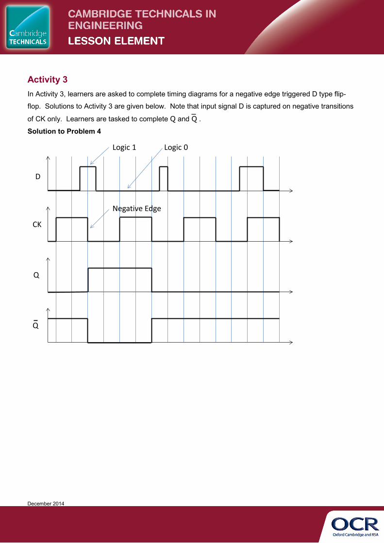
Activity 3 In Activity 3, learners are asked to complete timing diagrams for a negative edge triggered D type flip-
flop. Solutions to Activity 3 are given below. Note that input signal D is captured on negative transitions
of CK only. Learners are tasked to complete Q and Q .
Solution to Problem 4
CK
Q
D
Q
Logic 1 Logic 0
Negative Edge

December 2014
Solution to Problem 5
D
CK
Q
Q
Solution to Problem 6
D
CK
Q
Q
December 2014
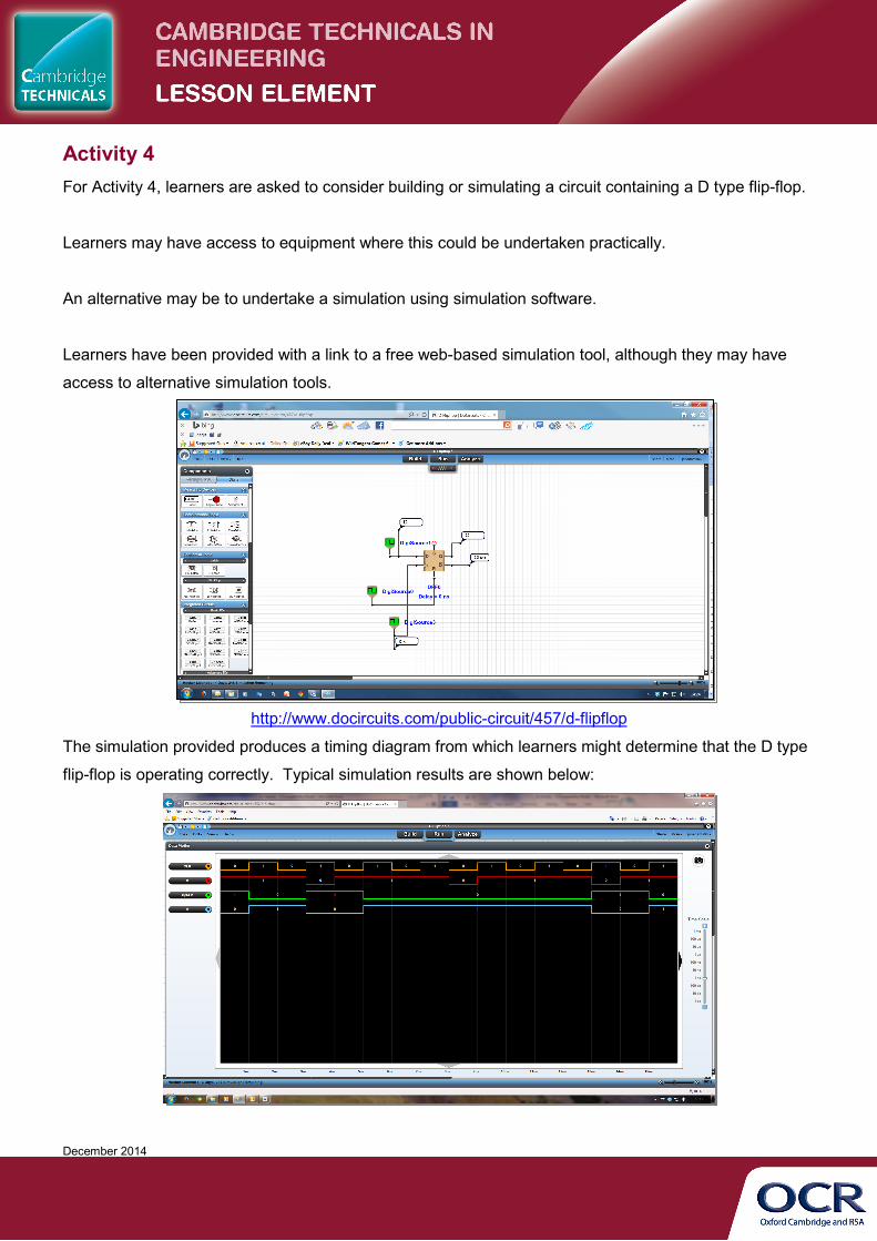
Activity 4 For Activity 4, learners are asked to consider building or simulating a circuit containing a D type flip-flop.
Learners may have access to equipment where this could be undertaken practically.
An alternative may be to undertake a simulation using simulation software.
Learners have been provided with a link to a free web-based simulation tool, although they may have
access to alternative simulation tools.
http://www.docircuits.com/public-circuit/457/d-flipflop
The simulation provided produces a timing diagram from which learners might determine that the D type
flip-flop is operating correctly. Typical simulation results are shown below:
December 2014
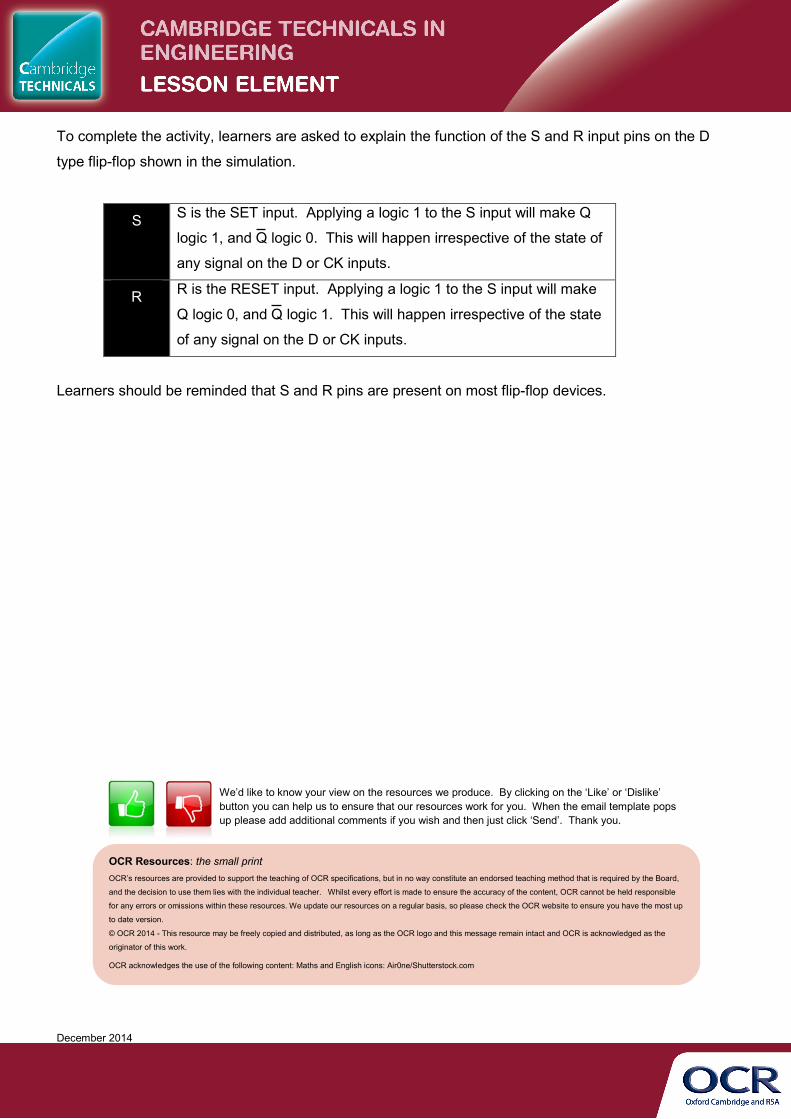
To complete the activity, learners are asked to explain the function of the S and R input pins on the D
type flip-flop shown in the simulation.
S S is the SET input. Applying a logic 1 to the S input will make Q
logic 1, and Q logic 0. This will happen irrespective of the state of
any signal on the D or CK inputs.
R R is the RESET input. Applying a logic 1 to the S input will make
Q logic 0, and Q logic 1. This will happen irrespective of the state
of any signal on the D or CK inputs.
Learners should be reminded that S and R pins are present on most flip-flop devices.
OCR Resources: the small print OCR’s resources are provided to support the teaching of OCR specifications, but in no way constitute an endorsed teaching method that is required by the Board,
and the decision to use them lies with the individual teacher. Whilst every effort is made to ensure the accuracy of the content, OCR cannot be held responsible
for any errors or omissions within these resources. We update our resources on a regular basis, so please check the OCR website to ensure you have the most up
to date version.
© OCR 2014 - This resource may be freely copied and distributed, as long as the OCR logo and this message remain intact and OCR is acknowledged as the
originator of this work.
OCR acknowledges the use of the following content: Maths and English icons: Air0ne/Shutterstock.com
We’d like to know your view on the resources we produce. By clicking on the ‘Like’ or ‘Dislike’ button you can help us to ensure that our resources work for you. When the email template pops up please add additional comments if you wish and then just click ‘Send’. Thank you.
Related Documents