UNIT 4 OPTICAL APPARATUS Structure 4.1 Introduction Objectives 4.2 Laws of Reflection and Refraction 4.3 Image Formation by Reflecting Surfaces Plane Mirror Spherical Mirrors 4.4 Image Formation by Refracting Surfaces Prism Lenses 4.5 Optical Instruments Microscopes Telescopes Spectrometer 4.6 Sources of Light Incandescent Sources Discharge Lamps 4.7 Summary 4.8 Terminal Questions 4.9 Solutions and Answers 4.1 INTRODUCTION In Unit 1 you have learnt that optical apparatus are used for conducting experiments with light. Light is responsible for our visual contact with our surroundings. In nature, we observe various interesting phenomena associated with light, such as solar and lunar eclipses, rainbows and mirage. These can be understood in terms of rectilinear propagation, reflection and refraction of light which follow certain basic laws. You can verifi these laws by conducting experiments in a laboratory. In the present unit, you will learn about optical apparatus available in a typical school or college laboratory, their handling and maintenance. In particular, we discuss how image formation by reflecting and refracting surfaces such as mirrors, lenses, prisms or their combination can be used to design optical instruments which extend our reach and enable us to learn more about nature. Finally we discuss light sources used in a physics lab to perform various experiments on optics. In the next unit you will learn about electrical instruments. Objectives After studying this unit, you should be able to: state the laws of reflection and refraction of light; define the terms principal axis, centre of curvature, radius of curvature, focus and focal length for spherical mirrors; distinguish between plane, concave and convex mirrors; explain image formation by plane, concave and convex mirrors; distinguish between convex and concave lenses;

Welcome message from author
This document is posted to help you gain knowledge. Please leave a comment to let me know what you think about it! Share it to your friends and learn new things together.
Transcript
UNIT 4 OPTICAL APPARATUS
Structure
4.1 Introduction Objectives
4.2 Laws of Reflection and Refraction 4.3 Image Formation by Reflecting Surfaces
Plane Mirror Spherical Mirrors
4.4 Image Formation by Refracting Surfaces Prism Lenses
4.5 Optical Instruments Microscopes Telescopes Spectrometer
4.6 Sources of Light Incandescent Sources Discharge Lamps
4.7 Summary 4.8 Terminal Questions 4.9 Solutions and Answers
4.1 INTRODUCTION
In Unit 1 you have learnt that optical apparatus are used for conducting experiments with light. Light is responsible for our visual contact with our surroundings. In nature, we observe various interesting phenomena associated with light, such as solar and lunar eclipses, rainbows and mirage. These can be understood in terms of rectilinear propagation, reflection and refraction of light which follow certain basic laws. You can verifi these laws by conducting experiments in a laboratory.
In the present unit, you will learn about optical apparatus available in a typical school or college laboratory, their handling and maintenance. In particular, we discuss how image formation by reflecting and refracting surfaces such as mirrors, lenses, prisms or their combination can be used to design optical instruments which extend our reach and enable us to learn more about nature. Finally we discuss light sources used in a physics lab to perform various experiments on optics. In the next unit you will learn about electrical instruments.
Objectives
After studying this unit, you should be able to:
state the laws of reflection and refraction of light; define the terms principal axis, centre of curvature, radius of curvature, focus and focal length for spherical mirrors; distinguish between plane, concave and convex mirrors; explain image formation by plane, concave and convex mirrors; distinguish between convex and concave lenses;
explain image formation by a compound microscope and a telescope; explain the working of a spectrometer; list commonly used sources of light in a phys~cs laboratory; and state the precautions in handling and maintenance of opticai apparatus.
Optical Apparatus
4.2 LAWS OF REFLECTION AND RERUCTION
The optical apparatus we discuss in this unit are essentially image forming devices. Image formation by these devices can be understood in terms of rectilinear propagation of light which means that light travels along a straight line. It can be depicted in the form of rays. Moreover, the following laws hold for propagation of light:
a) Laws of reflection, and b) Laws of refraction.
You must be familiar with these laws. But we state these to refresh your memory.
A. Laws of reflection
When light incident on a surface is reflected, the following laws hold:
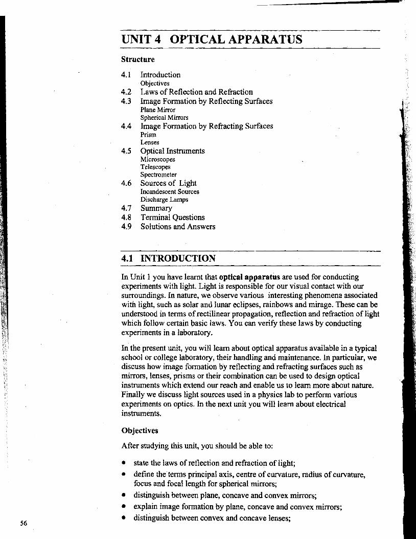
i) The angle of incidence is equal to the angle of reflection. ii) The incident ray, the reflected ray and the normal to the surface at the point
of incidence are in the same plane (Fig.4.1 j.
Fig.4.1: Reflection of light from a plane surface. The angle of incidence is equal to the angle of reflection; that is, L l O M = L1IfOB, and AO, OB and M O are in the plane AOB.
B. Laws of refraction nz ' , I
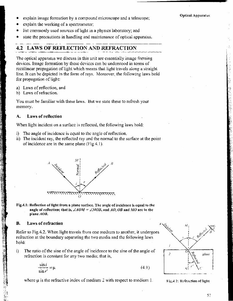
Refer to Fig.4.2. When light travels from one medium to another, it undergoes refraction at the boundary separating the two media and the following laws hold:
i
i) The ratio of the sine of the angle of incidence to the sine of the angle of refraction is constant for any two media; that is,
sin i -- -P (4.1 j sin r'
where p is the refractive index of medium 2 with respect to medium 1. F'i2.4 2: I i ~ f r ~ c t i o n of light
Basic Apparatus in Phvsics
When light is incident from a denser to a rarer medium, it is possible that at a particular angle of incidence, the angle of refraction becomes 90". Such an angle of incidence is called critical angle. When angle of incidence is greater than the critical angle, the ray is reflected back. This phenomenon is known as total internal reflection. It is responsible for optical illusion in mirage as well as brilliance of diamonds. Now-a-days it is also used in optical communication.
&Silver outing
Fig.4.3: An ordinary lane mirror
Fig.4.4: Image formed by a plane mirror is virtual
ii) The incident ray, the refracted ray and the normal NO lie in the same plane.
If light travels from a rarer (air) to a denser (glass) medium, it bends towards the normal. Conversely, if light travels from a denser medium to a rarer medium, it bends away from the normal. Note that in the latter case greater the refractive index of the medium of incidence, greater will be the deviation of the refracted ray from the normal. Media whose refractive indices are greater than unity (refractive index of air) are called optically denser media. Examples of such media are water, glass, transpaknt plastics, etc.
Before you proceed further, you may like to answer an SAQ.
SAQ 1: Reflection and refraction of light
a) Name the phenomenon observed in each of the following:
i) Looking glass used in homes ii) Spectacles; and iii)Rear view mirror used in motor cars and buses.
b) Glass is denser than water and water is denser than air. Draw the ray diagram when light travels from
i) water to glass ii) air to water iii) glass to air
In a typical physics laboratory, you will come across a variety of image forming optical apparatus such as plane mirrors, spherical mirrors and lenses. Image formation in mirrors is governed by the laws of reflection. In the following section, you will learn how images are formed by plane and spherical mirrors.
4.3 IMAGE FORMATION BY REFLECTING SURFACES
You are familiar wit11 a plane mirror. Have you ever thought how an image is formed in such a mirror? You may have observed that it is made of glass with e thin coating of shiny metal on one of its surfaces (Fig.4.3). This coating can be of silver, mercury or aluminium. The same holds true for spherical mirrors as well. In a plane mirror, coating can be applied on either surface of a glass plate. You may now ask: What purpose does the metallic coating serve? This makes it a reflectiqg surface. We can apply the laws of reflection to understand image formation by such a mirror.
4.3.1 Plane Mirror
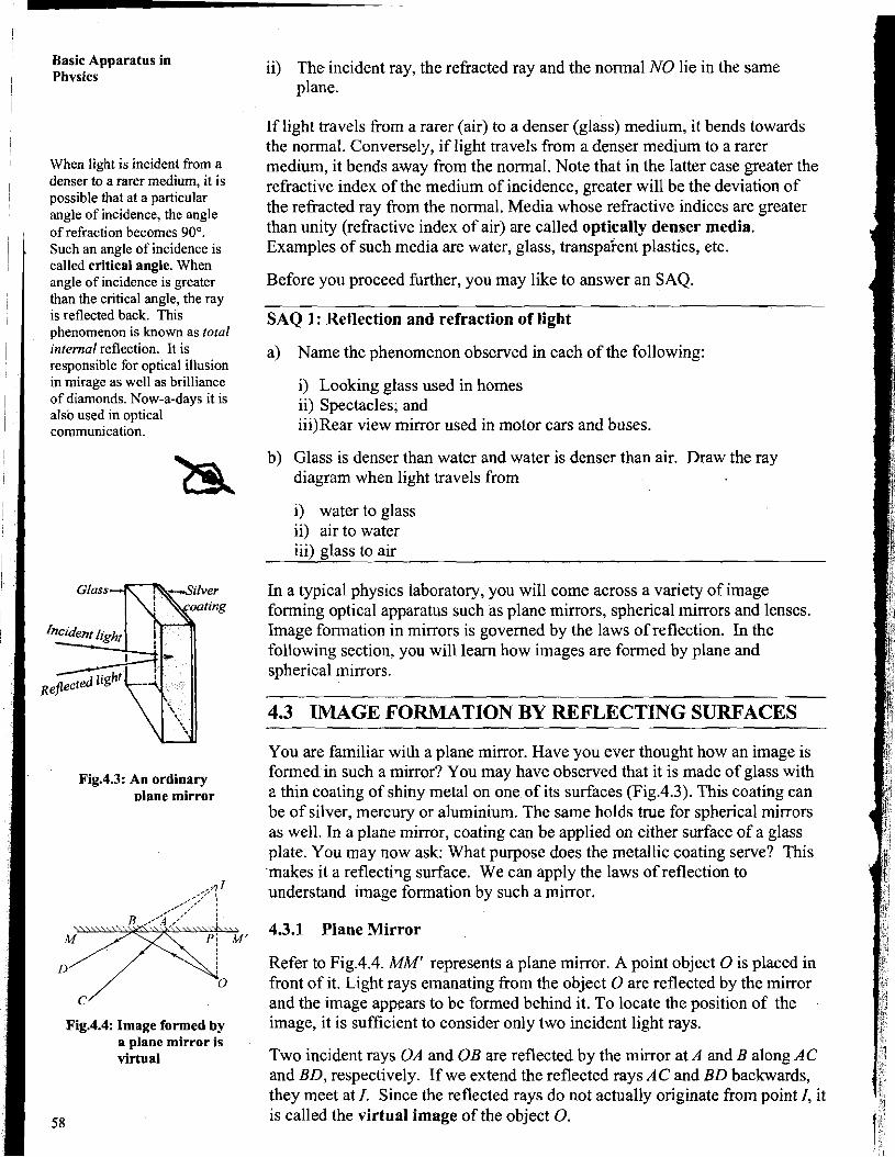
Refer to Fig.4.4. MM' represents a plane mirror. A point object 0 is placed in front of it. Light rays emanating from the object 0 are reflected by the mirror and the image appears to be formed behind it. To locate the position of the image, it is sufficient to consider only two incident light rays.
Two incident rays OA and OB are reflected by the mirror at A and B along AC and BD, respectively. If we extend the reflected rays AC and BD backwards, they meet at I. Since the reflected rays do not actually originate from point I, it is called the virtual image of the object 0.
If 0 and I are joined in a straight line, you will note that Optical Apparatus
i) OP = PI, that is, the image I is located as far behind the mirror as the object is in front of it, and
ii) the line 01 is perpendicular to the plane of the mirror. k If the object is of finite size, its image is laterally inverted and of the same size. Do you know what is meant by lateral inversion of an image? To understand this, you may stand in front of a mirror and raise your right hand. You will note that your image in the mirror raises its left hand. Similarly, if you place the letter E in front of the mirror, its image is seen as 3 (Fig.4.5).
To sum up, the image formed by a plane mirror is virtual, erect, laterally inverted, of the same size and located as far behind the mirror as the Fig.4.5: Laterally inverted object is in front of it. image formed by a
plane mirror Many a times, we need to obtain enlarged or smaller images of objects. For example, in the rear view mirror of an automobile, the images formed should be smaller so that the field of view is wide. Spherical mirrors serve this purpose well. We now discuss image formation by such mirrors.
4.3.2 Spherical Mirrors
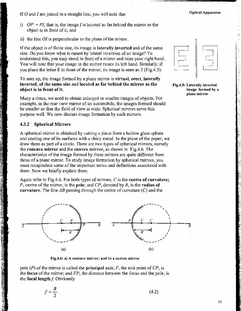
A spherical mirror is obtained by cutting a piece from a hollow glass sphere and coating one of its surfaces with a shiny metal. In the plane of the paper, we draw them as part of a circle. There are two types of spherical mirrors, namely the concave mirror and the convex mirror, as shown in Fig.4.6. The characteristics of the image formed by these mirrors are quite different from those of a plane mirror. To study image formation by spherical mirrors, you must recapitulate some of the important terms and definitions associated with them. Now we briefly explain them.
Again refer to Fig.4.6. For both types of mirrors, C is the centre of curvature; P, centre of the mirror, is the pole; and CP, denoted by R, is the radius of curvature. The line AB passing through the centre of curvature (C) and the
(a) (b)
Fig.4.6: a) A concave mirror; and b) a convex mirror
pole (P) of the mirror is called the principal axis; F, the mid point of CP, is the focus of the mirror; and FP, the distance between the focus and the pole, is the focal length$ Obviously
Basic Apparatus in Phvsics Now suppose you are given a spherical mirror and you are asked to locate its
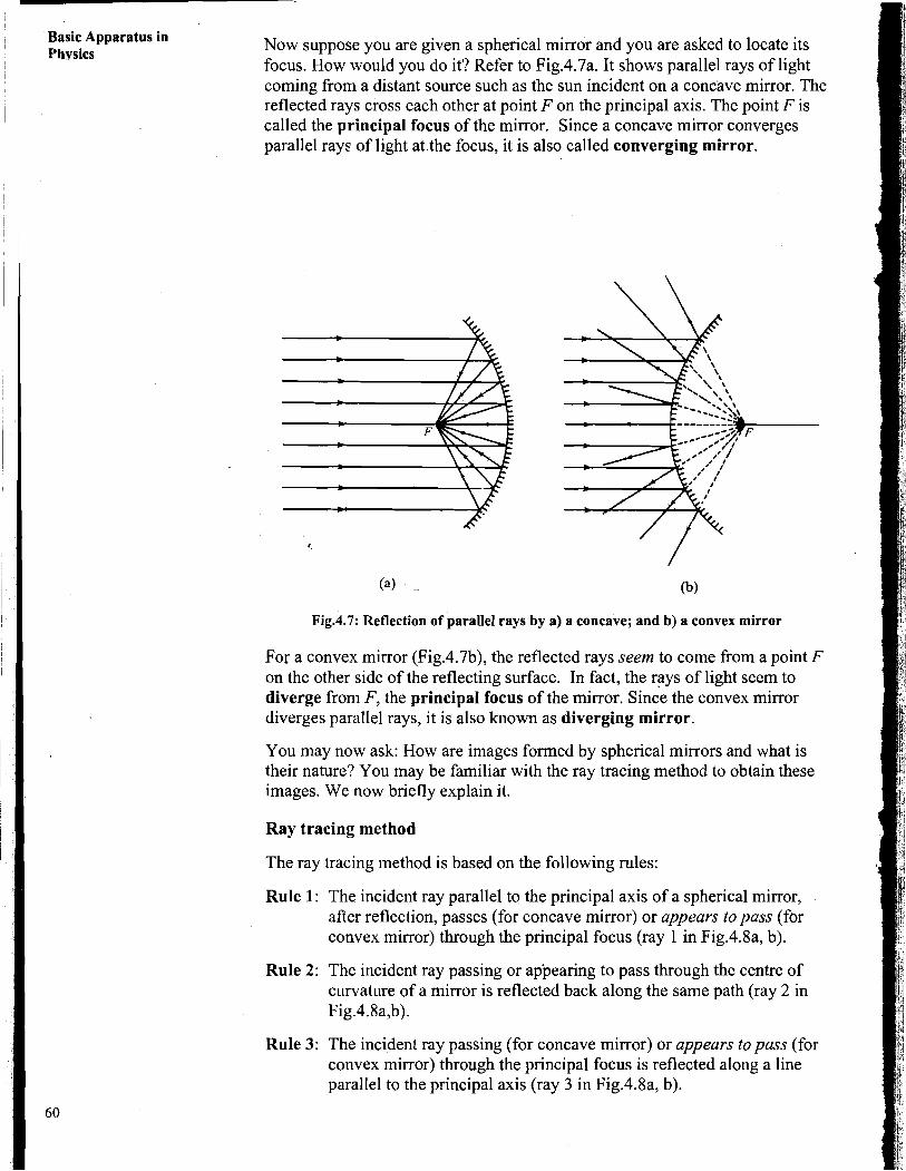
focus. How would you do it? Refer to Fig.4.7a. It shows parallel rays of light coming from a distant source such as the sun incident on a concave mirror. The reflected rays cross each other at point F on the principal axis. The point F is called the principal focus of the mirror. Since a concave mirror converges parallel rays of light at.the focus, it is also called converging mirror.
Fig.4.7: Reflection of parallel rays by a) a concave; and b) a convex mirror
For a convex mirror (Fig.4.7b), the reflected rays seem to come from a point F on the other side of the reflecting surface. In fact, the rays of light seem to diverge from F , the principal focus of the mirror. since the convex mirror diverges parallel rays, it is also known as diverging mirror.
You may now ask: How are images formed by spherical mirrors and what is their nature? You may be familiar with the ray tracing method to obtain these images. We now briefly explain it.
Ray tracing method
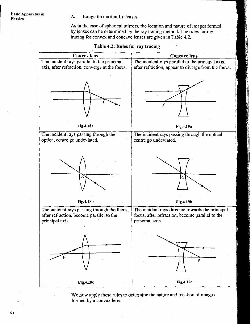
The ray tracing method is based on the following rules:
Rule 1: The incident ray parallel to the principal axis of a spherical mirror, after reflection, passes (for concave mirror) or appears to pass (for convex mirror) through the principal focus (ray 1 in Fig.4.8a, b).
Rule 2: The incident ray passing or appearing to pass through the centre of curvature of a mirror is reflected back along the same path (ray 2 in Fig.4.8a,b).
Rule 3: The incident ray passing (for concave mirror) or appears topass (for convex mirror) through the principal focus is reflected along a line parallel to the principal axis (ray 3 in Fig.4.8a, b).
Optical Apparatus
(a> '$1
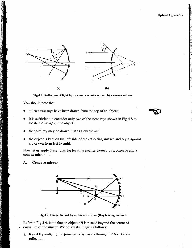
Fig.4.8: Reflection of light by a) a concave mirror; and b) a convex mirror
You should note that
at least two rays have been drawn from the top of an object; =m it is sufficient to consider only two of the three rays shown in Fig.4.8 to locate the image of the object;
the third ray may be drawn just as a check; and
the object is kept on the left side of the reflecting surface and ray diagrams are drawn from left to right.
Now let us apply these rules for locating images formed by a concave and a convex mirror. -
A. Concave mirror
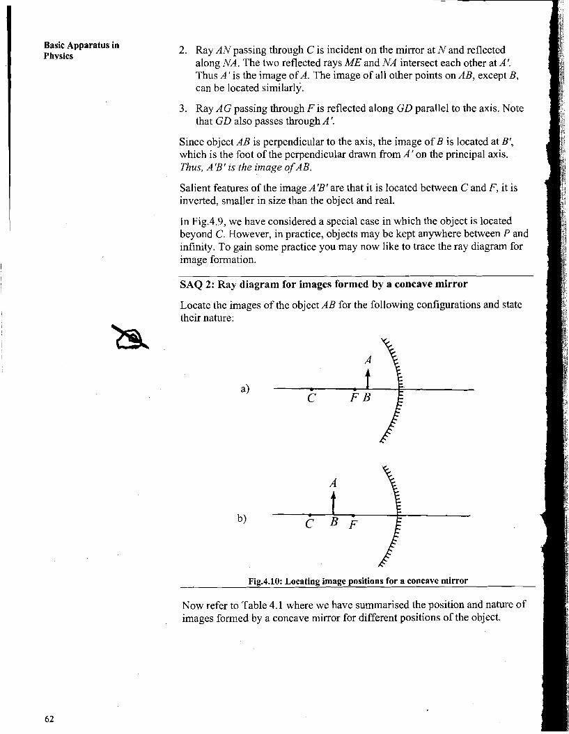
Fig.4.9: Image formed by a concave mirror (Ray tracing method)
Refer to Fig.4.9. Note that an object AB is placed beyond the centre of , curvature of the mirror. We obtain its image as follows:
1. Ray AM parallel to the principal axis passes through the focus F on reflection.
1 Basic Apparatus in I Phvsics
2. Ray AN passing through C is incident on the mirror at Nand reflected along NA. The two reflected rays ME and NA-intersect each other at A'. Thus A' is the image of A. The image of all other points on AB, except B, can be located similarly.
3. Ray AG passing through F is reflected along GD parallel to the axis. Note that GD also passes through A '.
Since object AB is perpendicular to the axis, the image of B is located at B', which is the foot of the perpendicular drawn from A' on the principal axis. Thus, A 'B ' is the image of AB.
Salient features of the image AfBf are that it is located between C and F, it is inverted, smaller in size than the object and real.
In Fig.4.9, we have considered a special case in which the object is located beyond C. However, in practice, objects may be kept anywhere between P and infinity. To gain some practice you may now like to trace the ray diagram for image formation.
SAQ 2: Ray diagram for images formed by a concave mirror
Locate the images of the object AB for the following configurations and state their nature:
Fig.4.10: Locating image positions for a concave mirror
Now refer to Table 4.1 where we have summarised the position and nature of images formed by a concave mirror for different positions of the object.
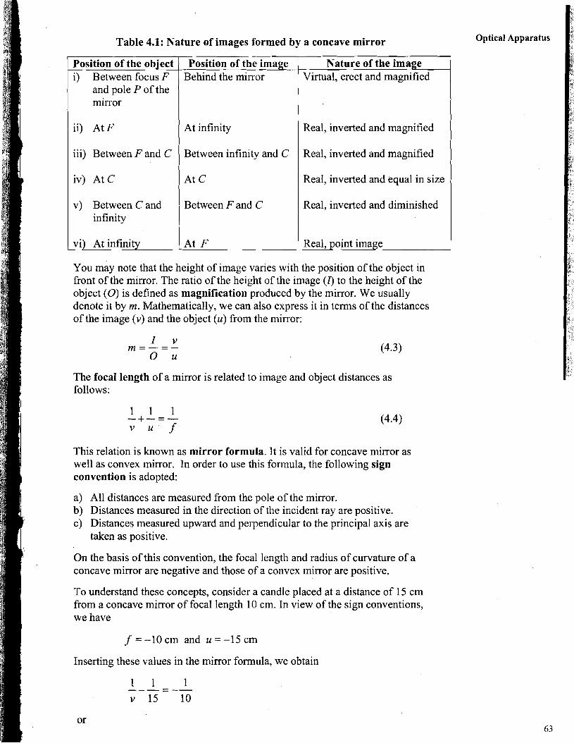
Table 4.1: Nature of images formed by a concave mirror Optical Apparatus
position of the i) Between
and pole P of the mirror
iii) Between F and C Between infinity and C Real, inverted and magnified
ii) At F I At infinity
iv) At C
Real, inverted and magnified
1 A t C Real, inverted and equal in size
v) Between C and infinity
You may note that the height of image varies with the position of the object in front of the mirror. The ratio of the height of the image (4 to the height of the object (0) is defined as magnification produced by the mirror. We usually denote it by m. Mathematically, we can also express it in terms of the distances of the image (v) and the object (u) from the mirror:
The focal length of a mirror is related to image and object distances as follows:
Between F and C
Real, point image vi) At infinity
This relation is known as mirror formula. It is valid for concave mirror as well as convex mirror. In order to use this formula, the following sign convention is adopted:
Real, inverted and diminished
At F
a) All distances are measured from the pole of the mirror. b) Distances measured in the direction of the incident ray are positive. c) Distances measured upward and perpendicular to the principal axis are
taken as positive.
On the basis of this convention, the focal length and radius of curvature of a concave mirror are negative and those of a convex mirror are positive.
To understand these concepts, consider a candle placed at a distance of 15 cm from a concave mirror of focal length 10 cm. In view of the sign conventions, we have
f =-10cm and u =-I5 cm
Inserting these values in the mirror formula, we obtain
Basic Apparatus in Phvdcs
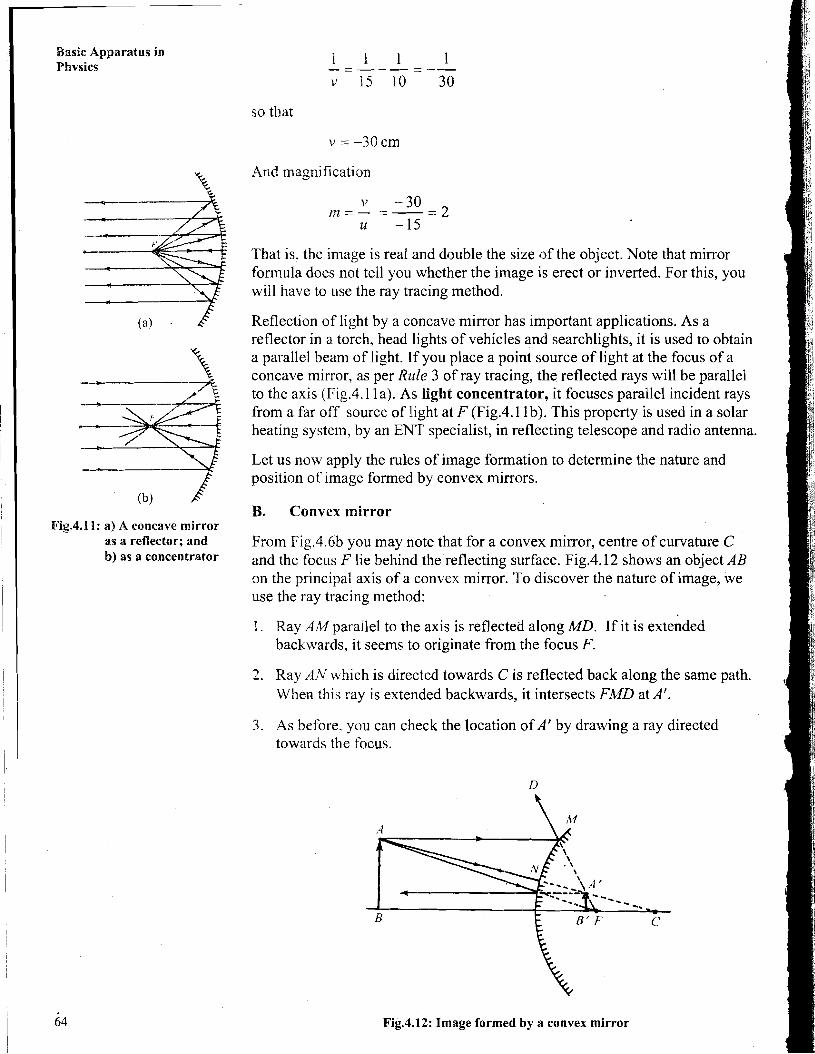
Fig,4.11: a) A concave mirror as a reflector; and b) as a concentrator
so that
And magnification
Tbat is, the image is real and double the size of the object. Note that mirror fonnula does not tell you whether the image is erect or inverted. For this, you will have to use the ray tracing method.
Reflection of light by a concave mirror has important applications. As a reflector in a torch, bead lights of vehicles and searchlights, it is used to obtain a parallel beam of light. If you place a point source of light at the focus of a concave mirror, as per Rule 3 of ray tracing, the reflected rays will be parallel to the axis (Fig.4.1 la). As light concentrator, it focuses parallel incident rays from a far off source of light at F (Fig.4.1 lb). This property is used in a solar heating system. by an ENT specialist, in reflecting telescope and radio antenna.
Let us now apply the rules of image formation to determine the nature and position of image formed by convex mirrors.
B. Convex mirror
From Fig.4.6b you may note that for a convex mirror, centre of curvature C and the focus F lie behind the reflecting surface. Fig.4.12 shows an object AB on the principal axis of a convex mirror. To discover the nature of image, we use the ray tracing method:
1. Ray AlWparallel to the axis is reflected along MD. If it is extended backwards, it seems to originate from the focus F.
2. Ray AN which is directcd towards C is reflected back along the same path. When this ray is extended backwards, it intersects FMD at A'.
3. As before, you can check the location of A' by drawing a ray directed towards the focus.
Fig.4.12: Image formed by a convex mirror
The image A'B' of the object AB is obtained by dropping a perpendicular from A' on the principal axis. You may note that this image is virtual, erect, diminished and behind the mirror.
Before proceeding further, you may like io answer an SAQ.
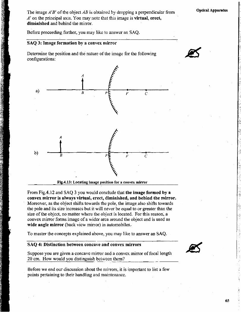
S A Q ' ~ : Image formation by a convex mirror
Determine the position and the nature of the image for the following configurations:
Fig.4.13: Locating image position for a convex mirror
From Fig.4.12 and SAQ 3 you would conclude that the image formed by a convex mirror is always virtual, erect, diminished, and behind the mirror. Moreover, as the object shifts towards the pole, the image.also shifts towards the pole and its size increases but it will never be equal to or greater than the size of the object, no matter where the object is located. For this reason, a convex mirror forms image of a wider area around the object and is used as wide angle mirror (back view mirror) in automobiles..
To master the concepts explained above, you may like to answer an SAQ.
Optical Apparatus
-
SAQ 4: Distinction between concave and convex mirrors
Suppose you are given a concave mirror and a convex mirror of focal length 20 cm, How would you distinguish between them?
Before we end our discussion about the mirrors, it is important to list a few points pertaining to their handling and maintenance.
Barie Apparatus in Phvaics
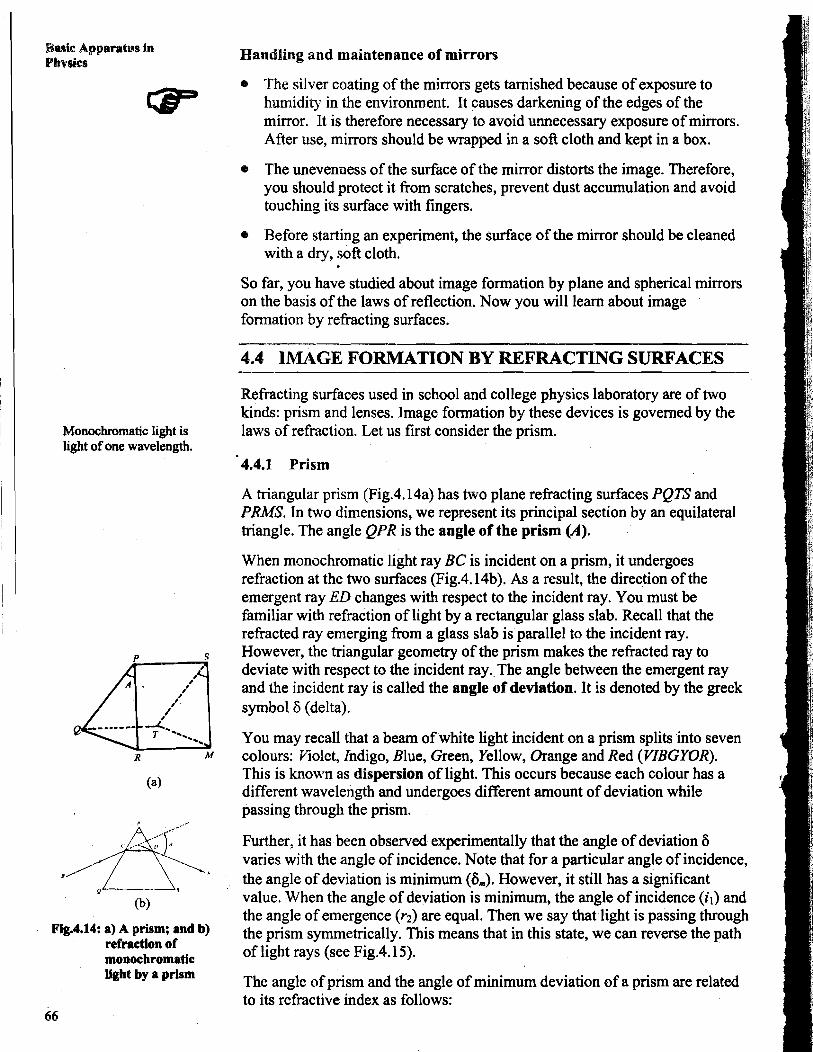
Monochromatic light is light of one wavelength.
FIg.4.14: a) A prism; and b) refraction of monochromatic light by a prism
Handling and maintenance of mirrors
The silver coating of the mirrors gets tarnished because of exposure to humidity in the environment. It causes darkening sf the edges of the mirror. It is therefore necessary to avoid unnecessary exposure of mirrors. After use, mirrors should be wrapped in a soft cloth and kept in a box.
The unevenness of the surface of the mirror distorts the image. Therefore, you should protect it from scratches, prevent dust accumulation and avoid touching its surface with fingers.
Before starting an experiment, the surface of the mirror should be cleaned with a dry, soft cloth.
So far, you have studied about image formation by plane and spherical mirrors on the basis of the laws of reflection. Now you will learn about image formation by refracting surfaces.
4.4 IMAGE FORMATION BY REFRACTING SURFACES
Refracting surfaces used in school and college physics laboratory are of two kinds: prism and lenses. Image formation by these devices is governed by the laws of refraction. Let us first consider the prism.
4.4.1 Prism
A triangular prism (Fig.4.14a) has two plane refracting surfaces PQTS and PRMS. In two dimensions, we represent its principal section by an equilateral triangle. The angle QPR is the angle of the prism (A).
When monochromatic light ray BC is incident on a prism, it undergoes refraction at the two surfaces (Fig.4.14b). As a result, the direction of the emergent ray ED changes with respect to the incident ray. You must be familiar with refraction of light by a rectangular glass slab. Recall that the refracted ray emerging from a glass slab is parallel to the incident ray. However, the triangular geometry of the prism makes the refracted ray to deviate with respect to the incident ray. The angle between the emergent ray and the incident ray is called the angle of deviation. It is denoted by the greek symbol 6 (delta).
You may recall that a beam of white light incident on a prism splits into seven colours: Violet, Indigo, Blue, Green, Yellow, Orange and Red (VIBGYOR). This is known as dispersion of light. This occurs because each colour has a different wavelength and undergoes different amount of deviation while passing through the prism.
Further, it has been observed experimentally that the angle of deviation 6 varies with the angle of incidence. Note that for a particular angle of incidence, the angle of deviation is minimum (6,). However, it still has a significant value. When the angle of deviation is minimum, the angle of incidence (il) and the angle of emergence (rz) are equal. Then we say that light is passing through the prism symmetrically. This means that in this state, we can reverse the path of light rays (see Fig.4.15).
The angle of prism and the angle of minimum deviation of a prism are related to its refractive index as follows:
,) l'=
sin ($1 While handling prisms you should take the same precautions as were mentioned for mirrors. We now discuss lenses.
4.4.2 Lenses
Like spherical mirrors, lenses are also divided into two categories, namely the convex (or converging) lens and the concave (or diverging) lens (Fig.4.16). You may note that convex and concave lenses are of three types. These are shown in FigA. 16. You can differentiate a concave lens fiom a convex lens by touching as well as on the basis of the image formed by them. As is evident from Fig.4.16, the convex lens is thicker in the middle compared to its edges, whereas the concave lens is thinner in the middle. However, if the radius of curvature is very large, as in the case of lenses used in spectacles, identifLing them by touch may not be possible. It can then be done only through image formation.
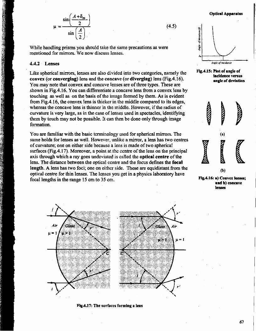
You are familiar with the basic terminology used for spherical mirrors. The same holds for lenses as well. However, unlike a mirror, a lens has two centres of curvature; one on either side because a lens is made of two spherical surfaces (Fig.4.17). Moreover, a point at the centre of the lens on the principal axis through which a ray goes undeviated is called the optical centre of the lens. The distance between the optical centre and the focus defines the focal length. A lens has two foci; one on either side. These are equidistant fiom the optical centre for thin lenses. The lenses you get in a physics laboratory have focal lengths in the range 15 cm to 35 cm.
Optical Apparatus
Fig.4.15: Plot of angle of incidence versus angle of deviation
Fig.4.16: a) Convex lenses; and b) concave lenses
Fig.4.17: The surfaces forming a lens
Basic Apparatus in Physics
Convex lens Optical ~pparatus
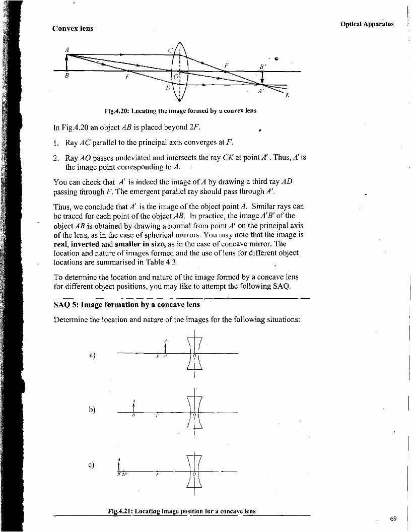
Fig.4.20: Locating the image formed by a convex lens
In Fig.4.20 an object AB is placed beyond 2F. •
1. Ray AC parallel to the principal axis converges at F.
2. Ray A 0 passes undeviated and intersects the ray C K at point A'. Thus, A' is the image point corresponding to A.
You can check that A' is indeed the image of A by drawing a third ray A D passing through F. The emergent parallel ray should pass through A'.
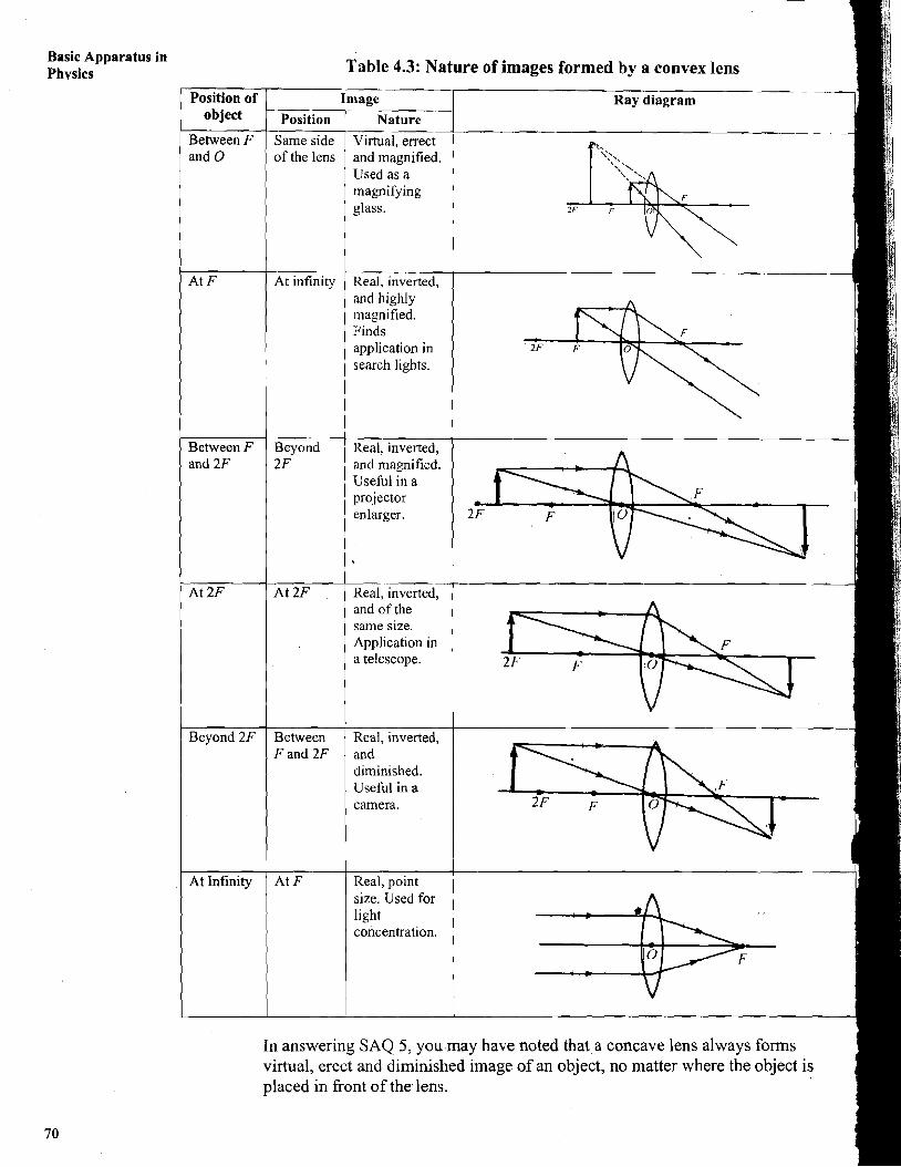
Thus, we conclude that A' is the image of the object point A. Similar rays can be traced for each point of the object AB. In practice, the image A'B' of the object AB is obtained by drawing a normal from point A' on the principal axis of the lens, as in the case c?f spherical mirrors. You may note that the image is real, inverted and smaller in size, as in the case of concave mirror. The location and nature of images formed and the use of lens for different object locations are summarised in Table 4.3.
To determine the location and nature of the image formed by a concave lens for different object positions, you may like to attempt the following SAQ.
SAQ 5: Image formation by a concave lens
Determine the location and nature of the images for the following situations:
Fig.4.21: Locating image position for a concave lens
Basic Apparatus in Phvsics
For the magnification produced by a lens, Eq. (4.3) holds. However, due to sign convention, the lens formula takes the form
where u is the distance of the object from the lens, v is the distance of the image from the lens and f is the focal length of the lens.
B. Power of a lens: diopter
The ability of a lens to converge or diverge light is expressed in terms of its power. It is defined as reciprocal of the focal length of a lens and its unit is diopter:
Power (in diopter) = 1
focal length (in metre)
The shorter the focal length of a lens, the more it converges or diverges light and the more powerful .it is said to be.
While handling lenses, you should take the same precautions as mentioned for mirrors (Section 4.3).
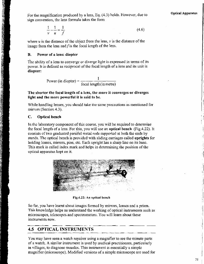
C. Optical bench
In the laboratory component of this course, you will be required to determine the focal length of a lens. For this, you will use an optical bench (Fig.4.22). It consists of two graduated parallel metal rods supported at both the ends by stands. The optical bench is provided with sliding carriages called uprights for holding lenses, minors, pins, etc. Each upright has a sharp line on its base. This mark is called index mark and helps in determining the position of the optical apparatus kept on it.
Fig.4.22: An optical bench
So far, you have learnt about images formed by mirrors, lenses and a prism. This knowledge helps us understand the working of optical instruments such as microscopes, telescopes and spectrometers. You will learn about these instruments now.
4.5 OPTICAL INSTRUMENTS
Optical Apparatus
You may have seen a watch repairer using a magnifier to see the minute parts of a watch. A similar instrument is used by medical practitioners, particularly in villages, to diagnose measles. This instrument is essentially a simple magnifier (microscope). Modified versions of a simple microscope are used for
Basic Apparatus in Phvsics biological investigations to examine the presence of bacteria, cells, parasites,
etc. We now discuss these in some detail.
4.5.1 Microscopes
A microscope is an optical instrument used for obtaining magnified images of very small objects. The magnified image is obtained with the help of a convex lens or a pair of convex lenses. In the laboratory component of this course, you will get an opportunity to work with two types of microscopes, namely the simple microscope and the compound microscope
A, Simple microscope
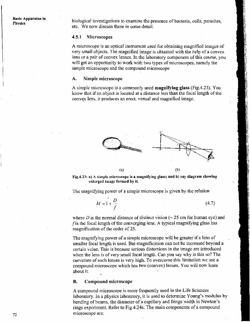
A simple microscope is a commonly used magnifying glass (Fig.4.23). You know that if an object is located at a distance less than the focal length of the convqx lens, it produces an erect, virtual and magnified image.
Fig.4.23: a) A simple microscope is a magnifying glass; and b) ray diagram showing enlarged image formed by it.
The magnifying power of a simple microscope is given by the relation
where D is the normal distance of distinct vision (- 25 cm for human eye) and f is the focal length of the converging lens. A typical magnifying glass has magnification of the order of 25.
The magnifying power of a simple microscope will be greater if a lens of smaller focal length is used. But magnification can not be increased beyond a certain value. This is because serious distortions in the image are introduced when the lens is of very small focal length. Can you say why is this so? The curvature of such lenses is very high. To overcome this limitation we use a compound microscope which has two (convex) lenses. You will now learn about it.
B. Compound microscope
A compound microscope is more frequently used in the Life Sciences laboratory. In a physics laboratory, it is used to determine Young's modulus by bending of beams, the diameter of a capillary and fringe width in Newton's rings experiment. Refer to Fig.4.24a. The main components of a compound microscope are:
Optical Apparatus a metal tube which holds two convex lenses, the objective L1 and the eye piece L2;
0 a graduated steel beam along which a movable vernier scale arrangement is provided; knobs and screws to control the horizontal and vertical movements of the tube; and a heavy base with levelling screws.
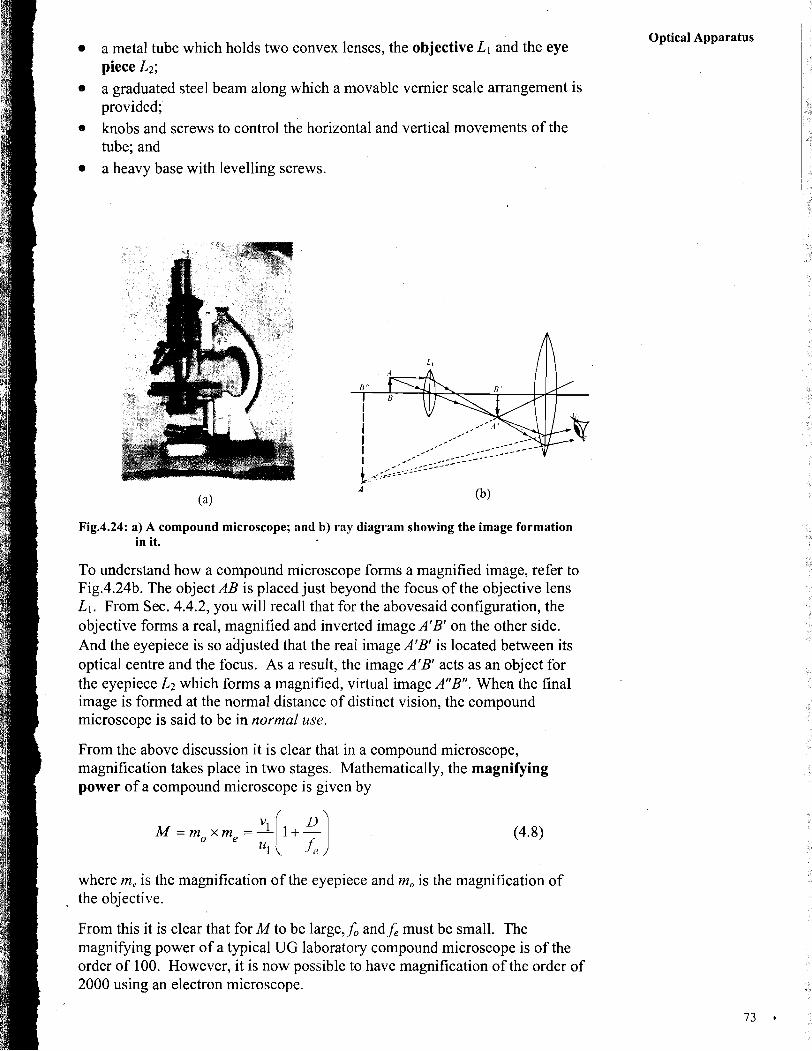
Fig.4.24: a) A compound microscope; and b) ray diagram showing the image formation in it.
To understand how a compound microscope forms a magnified image, refer to Fig.4.24b. The object AB is placed just beyond the focus of the objective lens L1. From Sec. 4.4.2, you will recall that for the abovesaid configuration, the objective forms a real, magnified and inverted image A'B' on the other side. And the eyepiece is so adjusted that the real image A'B' is located between its optical centre and the focus. As a result, the image A'B' acts as an object for the eyepiece L2 which forms a magnified, virtual image AnB". When the final image is formed at the normal distance of distinct vision, the compound microscope is said to be in normal use.
From the above discussion it is clear that in a compound microscope, magnification takes place in two stages. Mathematically, the magnifying power of a compound microscope is given by
where me is the magnification of the eyepiece and m, is the magnification of the objective.
From this it is clear that for M to be large& and,f, must be small. The magnifying power of a typical UG laboratory compound microscope is of the order of 100. However, it is now possible to have magnification of the order of 2000 using an electron microscope.
Basic Apparatus in Physics Handling and maintenance
a) Since a compound microscope is used for observing very small objects, it must be protected from dust. Therefore, when not in use, it should be covered by a soft cloth or kept in a box. .
b) If the microscope is to be moved from one place to another, make sure that you hold it properly; put one, hand beneath the base to support it and hold the vertical beam by the other hand. Never lift it by any fragile part!
c) As for any lens, the objective and the eyepiece should not be touched by fingers. These should'be regularly cleaned with a soft and dry cloth.
The compound microscope is widely used in a biology laboratory. You will work with this instrument extensively in the course Laboratory Techniques in Biology (LT-02) of this programme.
You may now like to answer an SAQ. -
SAQ 6: A compound microscope
You are given two lenses of focal lengths 5 cm and 50 cm. Which lens will vou recommend as the eve~iece of a com~ound microsco~e and why?
The first telescope was built by Hans Lippershey in 1608. Later Galileo invented a much improved telescope to see heavenly bodies.
The objective of a telescope has a large focal length and bigger aperture compared to the eyepiece.
4.5.2 Telescopes
You might have used a binocular during a cricket match to see the players in action. It forms enlarged images of distant objects, which are not distinctly visible to the unaided eye, and brings them nearer to the eye. A binocular, which is essentially a telescope, collects light over a large surface and concentrates it at a point producing a brighter image.
You may have lzarnt that telescopes are classified into two categories: refracting telescopes and reflecting telescopes. A refracting telescope uses a pair of lenses and a reflecting telescope uses a combination of a lens and a mirror. Refracting telescopes are also of two types: astronomical telescope and terrestrial telescope. In an UG physics laboratory, you will work only with refracting telescopes and for this reason we consider only these here.
A. Refracting astronomical telescope
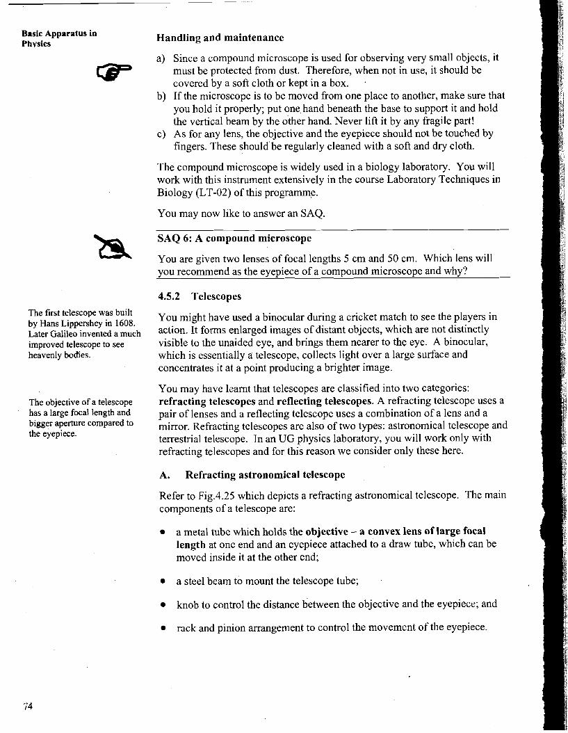
Refer to Fig.4.25 which depicts a refracting astronomical telescope. The main components of a telescope are:
a metal tube which holds the objective - a convex lens of large focal length at one end and an eyepiece attached to a draw tube, which can be moved inside it at the other end;
a steel beam to mount the telescope tube;
knob to control the distance between the objective and the eyepiece; and
rack and pinion arrangement to control the movement of the eyepiece.
Optical Apparatus
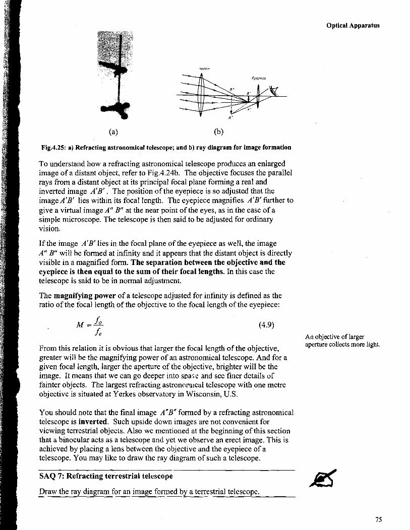
Fig.4.25: a) Refracting astronomical telescope; and b) ray diagram for image formation
To understand how a refracting astronomical telescope produces an enlarged image of a distant object, refer to Fig.4.24b. The objective focuses the parallel rays from a distant object at its principal focal plane forming a real and inverted image A'B' . The position of the eyepiece is so adjusted that the image A'B' lies within its focal length. The eyepiece magnifies A'B' further to give a virtual image A" B" at the near point of the eyes, as in the case of a simple microscope. The telescope is then said to be adjusted for ordinary vision.
If the image A'B' lies in the focal plane of the eyepiece as well, the image A" B" will be formed at infinity and it appears that the distant object is directly visible in a magnified form. The separation between the objective and the eyepiece is then equal to the sum of their focal lengths. In this case the telescope is said to be in normal adjustment.
The magnifying power of a telescope adjusted for infinity is defined as the ratio of the focal length of the objective to the focal length of the eyepiece:
(4.9) An objective of larger
From this relation it is obvious that larger the focal length of the objective, aperture collects more light.
greater will be the magnifying power of an astronomical telescope. And for a given focal length, larger the aperture of the objective, brighter will be the image. It means that we can go deeper into sPa:e and see finer details of
I fainter objects. The largest refracting astronomrcal telescope with one metre objective is situated at Yerkes observatory in Wisconsin, U.S.
You should note that the final image AnBn formed by a refracting astronomical telescope is inverted. Such upside down images are not convenient for viewing terrestrial objects. Also we mentioned at the beginning of this section that a binocular acts as a telescope and yet we observe an erect image. This is achieved by placing a lens between the objective and the eyepiece of a telescope. You may like to draw the ray diagram of such a telescope.
SAQ 7: Refracting terrestrial telescope P( Draw the ray diagram for an image formed by a terrestrial telescope.
( Now-a-days, telescopes which collect radiations other than visible light to obtain magnified images have been built and installed on earth as well as in space.
The turn-table is also called prism table.
While answering SAQ 7, you must have noted that the addition of a convex lens increases the length of the tube of a terrestrial telescope. To overcome this problem, it is also possible to use a prism instead of a convex lens. In modern binoculars, a prism is used so as to keep it compact.
In a refracting telescope, images may have coloured fringes around them due to chromatic abberation. To overcome this disadvantage, the objective in a reflecting telescope is replaced by a concave mirror. We would like you to draw the ray diagram for the image formed by a reflecting telescope.
The spectrometer is another very useful instrument used to analyse visible light in a physics laboratory. Note that a spectrometer is not an image forming instrument. In the lab component of this course, you will be required to d?at least one experiment with spectrometer. It is, therefore, important to learn about it.
4.5.3 Spectrometer
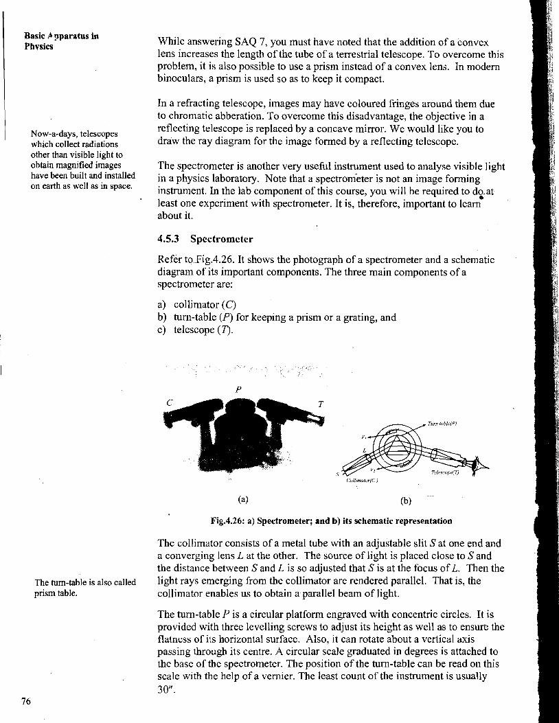
Refer to Fig.4.26. It shows the photograph of a spectrometer and a schematic diagram of its important components. The three main components of a spectrometer are:
a) collimator ( C ) b) turn-table (P) for keeping a prism or a grating, and C) telescope (T).
Fig.4.26: a) Spectrometer; and b) its schematic representation
The collimator consists of a metal tube with an adjustable slit S at one end and a converging lens L at the other. The source of light is placed close to S and the distance between S and L is so adjusted that S is at the focus of L. Then the light rays emerging from the collimator are rendered parallel. That is, the collimator enables us to obtain a parallel beam of light.
The turn-table P is a circular platform engraved with concentric circles. It is provided with three levelling screws to adjust its height as well as to ensure the flatness of its horizontal surface. Also, it can rotate about a vertical axis passing through its centre. A circular scale graduated in degrees is attached to the base of the spectrometer. The position of the turn-table can be read on this scale with the help of a vernier. The least count of the instrument is usually 30".
An astronomical telescope T enables us to examine the spectrum produced by a prism or a grating placed on the turn-table. The telescope can also be rotated about the same axis as that of the turn-table. The angle of rotation of the telescope can be measured on the graduated circular scale. The turn table and the telescope can be fixed in any desired position.
Before using the spectrometer, it is important to:
level the base, prism table, the collimator and the telescope using a spirit level and the levelling screws;
- adjust the eyepiece of the telescope so that the cross-wires are clearly visible; and
set the telescope so that the image of the distant object coincides with the cross-wires without any parallax.
A. Handling and maintenance of a spectrometer
a) Alignment of the collimator, the turn-table and the telescope is very sensitive. These components should therefore be handled gently. Jerky movement may disturb the alignment of these components.
b) When not in use, the spectrometer should be kept in an almirah to protect it from dust.
c) For smooth movement, the turn-table and the telescope may be oiled.
You have already learnt about a prism and how it disperses white light into its constituent colours. Grating is another device which enables us to obtain and analyse a spectrum.
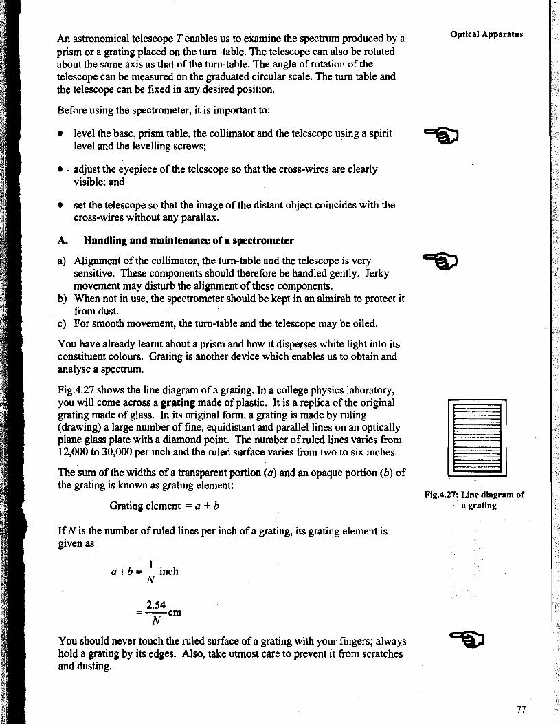
Fig.4.27 shows the line diagram of a grating. In a college physics laboratory, you will come across a grating made of plastic. It is a replica of the original grating made of glass. In its original form, a grating is made by ruling (drawing) a large number of fine, equidistant and parallel lines on an optically plane glass plate with a diamond point. The number of ruled lines varies from 12,000 to 30,000 per inch and the ruled surface varies from two to six inches.
The sum of the widths of a transparent portion (a) and an opaque portion (b) of the grating is known as grating element:
Grating element = a + b
If N is the number of ruled lines per inch of a grating, its grating element is given as
Optical Apparatus 1
Fig.4.27: Line diagram of a grating
You should never touch the ruled surface of a grating with your fingers; always hold a grating by its edges. Also, take utmost care to prevent it from scratches and dusting.
Basic Apparatus in Phvsics For conducting any optical experiment, we need a source of light. In a physics
laboratory, light from different sources is used. You will learn about some of them now.
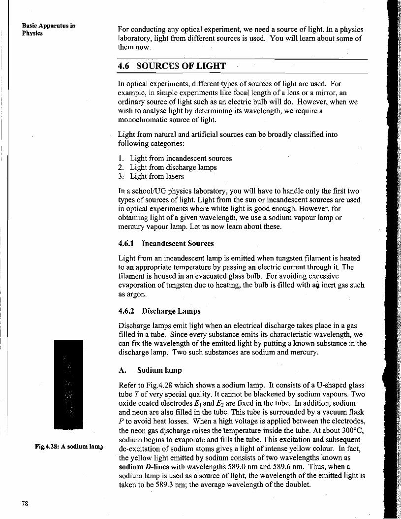
Fig.4.28: A sodium lamp
4.6 SOURCES OF LIGHT
In optical experiments, different types of sources of light are used. For example, in simple experiments like focal length of a lens or a mirror, an ordinary source of light such as an electric bulb will do. However, when we wish to analyse light by determining its wavelength, we require a monochromatic source of light.
Light from natural and artificial sources can be broadly classified into following categories:
1. Light from incandescent sources 2. Light from discharge lamps 3. Light from lasers
In a school/UG physics laboratory, you will have to handle only the first two types of sources of light. Light from the sun or incandescent sources are used in optical experiments where white light is good enough. However, for obtaining light of a given wavelength, we use a sodium vapour lamp or mercury vapour lamp. Let us now learn about these.
4.6.1 Incandescent Sources
Light from an incandescent lamp is emitted when tungsten filament is heated to an appropriate temperature by passing an electric current through it. The filament is housed in an evacuated glass bulb. For avoiding excessive evaporation of tungsten due to heating, the bulb is filled with ap inert gas such as argon.
4.6.2 Discharge Lamps
Discharge lamps emit light when an electrical discharge takes place in a gas filled in a tube. Since every substance emits its characteristic wavelength, we can fix the wavelength of the emitted light by putting a known substance in the discharge lamp. Two such substances are sodium and mercury.
A. Sodium lamp
Refer to Fig.4.28 which shows a sodium lamp. It consists of a U-shaped glass tube T of very special quality. It cannot be blackened by sodium vapours. Two oxide coated electrodes El and Ez are fixed in the tube. In addition, sodium and neon are also filled in the tube. This tube is surrounded by a vacuum flask P to avoid heat losses. When a high voltage is applied between the electrodes, the neon gas discharge raises the temperature inside the tube. At about 300°C, sodium begins to evaporate and fills the tube. This excitation and subsequent de-excitation of sodium atoms gives a light of intense yellow colour. In fact, the yellow light emitted by sodium consists of two wavelengths known as sodium D-lines with wavelengths 589.0 nm and 589.6 nm. Thus, when a sodium lamp is used as a source of light, the wavelength of the emitted light is taken to be 589.3 nm; the average wavelength of the doublet.
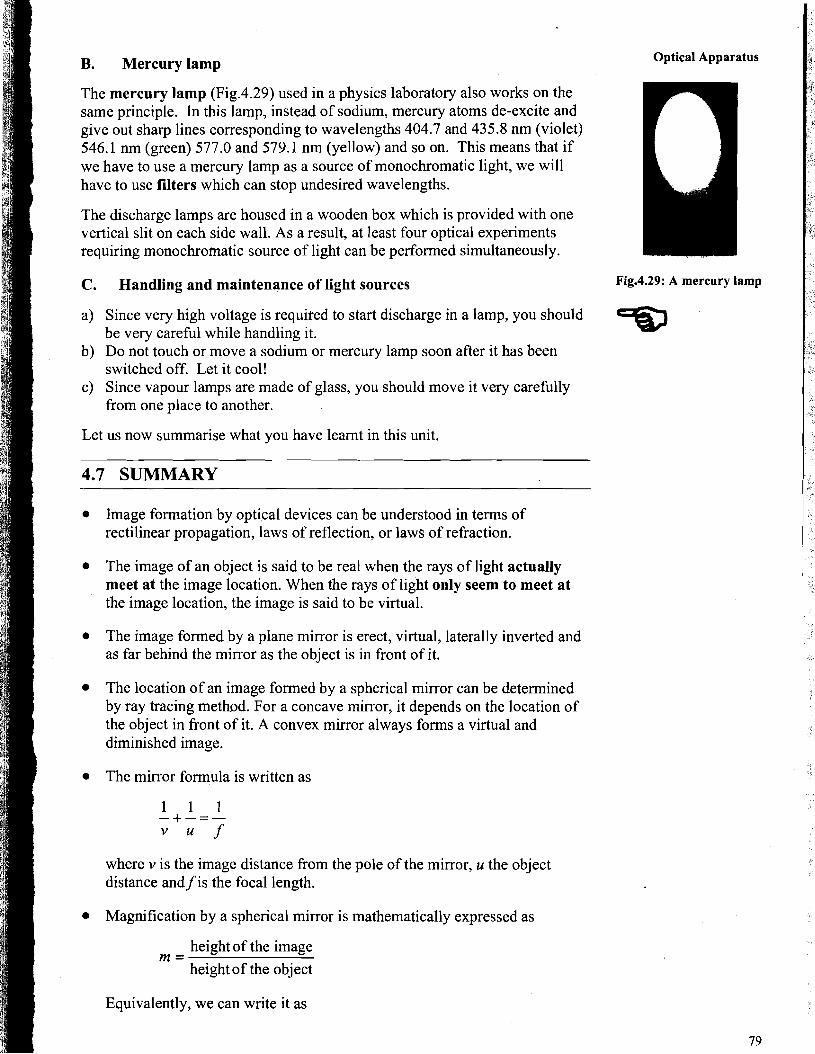
B. Mercury lamp
The mercury lamp (Fig.4.29) used in a physics laboratory also works on the same principle. In this lamp, instead of sodium, mercury atoms de-excite and give out sharp lines corresponding to wavelengths 404.7 and 435.8 nm (violet) 546.1 nm (green) 577.0 and 579.1 nm (yellow) and so on. This means that if we have to use a mercury lamp as a source of monochromatic light, we will have to use filters which can stop undesired wavelengths.
The discharge lamps are housed in a wooden box which is provided with one vertical slit on each side wall. As a result, at least four optical experiments requiring monochromatic source of light can be performed simultaneously.
Optical Apparatus
C. Handling and maintenance of light sources Fig.4.29: A mercury lamp
a) Since very high voltage is required to start discharge in a lamp, you should be very careful while handling it.
b) Do not touch or move a sodium or mercury lamp soon after it has been
=m switched off. Let it cool!
c) Since vapour lamps are made of glass, you should move it very carefully from one place to another.
Let us now summarise what you have learnt in this unit.
4.7 SUMMARY
Image formation by optical devices can be understood in terms of rectilinear propagation, laws of reflection, or laws of refraction.
The image of an object is said to be real when the rays of light actually meet at the image location. When the rays of light only seem to meet at the image location, the image is said to be virtual.
The image formed by a plane mirror is erect, virtual, laterally inverted and as far behind the mirror as the object is in front of it.
The location of an image formed by a spherical mirror can be determined by ray tracing method. For a concave mirror, it depends on the location of the object in front of it. A convex mirror always forms a virtual and diminished image.
The mirror formula is written as
where v is the image distance from the pole of the mirror, u the object distance and f is the focal length.
Magnification by a spherical mirror is mathematically expressed as
height of the image m =
height of the object
Equivalently, we can write it as
Basic Apparatus in Phvsics
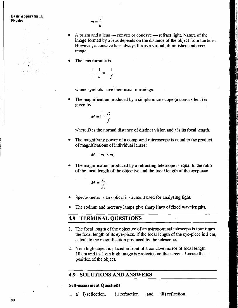
A prism and a lens - convex or concave - refract light. Nature of the image formed by a lens depends on the distance of the object from the lens. However, a concave lens always forms a virtual, diminished and erect image.
The lens formula is
where symbols have their usual meanings.
The magnification produced by a simple microscope (a convex lens) is given by
where D is the normal distance of distinct vision and f is its focal length.
The magnifying power of a compound microscope is equal to the product of magnifications of individual lenses:
The magnification produced by a refracting telescope is equal to the ratio of the focal length of the objective and the focal length of the eyepiece:
Spectrometer is an optical instrument used for analysing light.
The sodium and mercury lamps give sharp lines of fixed wavelengths.
4.8 TERMINAL QUESTIONS
1. The focal length of the'objective of an astronomical telescope is four times the focal length of its eye-piece. If the focal length of the eye-piece is 2 cm, calculate the magnification produced by the telescope.
2. 5 cm high object is placed in front of a concave mirror of focal length 10 cm and its 1 cm high image is projected on the screen. Locate the position of the object.
4.9 SOLUTIONS AND ANSWERS - - -
Self-assessment Questions
1. a) i) reflection, ii) refraction and . iii) reflection
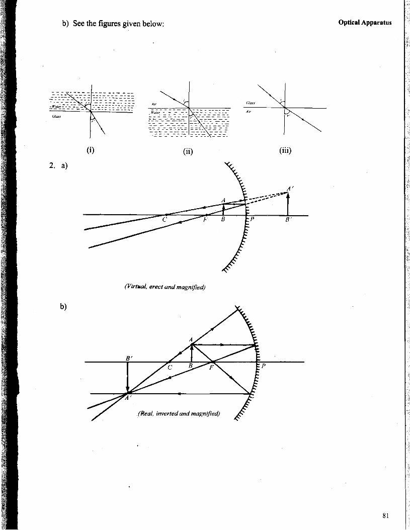
b) See the figures given below:
(ii) (iii)
(Pirfuol, erect and magniJied)
Optical Apparatus
Basic Apparatus in Phvsics
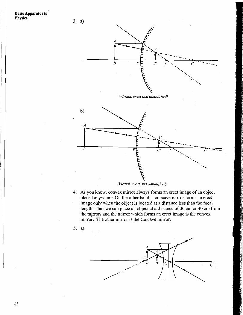
(Virtual, erect and diminished)
(Virtual, erect and diminished)
4. As you know, convex mirror always forms an erect image of an object placed anywhere. On the other hand, a concave mirror forms an erect image only when the object is located at a distance less than the focal length. Thus we can place an object at a distance of 30 cm or 40 cm from the mirrors and the mirror which forms an erect image is the convex mirror. The other mirror is the concave mirror.
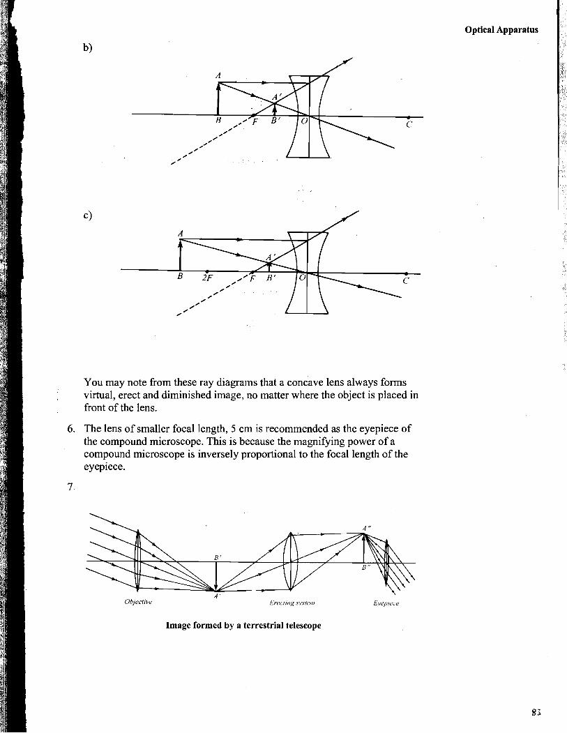
You may note from these ray diagrams that a concave lens always forms virtual, erect and diminished image, no matter where the object is placed in front of the lens.
6. The lens of smaller focal length, 5 cm is recommended as the eyepiece of the compound microscope. This is because the magnifying power of a compound microscope is inversely proportional to the focal length of the eyepiece.
Optical Apparatus
Objective Erecting systetii
Image formed by a terrestrial telescope
Terminal Questions
1. We have
f, = 20cm and fo = 4 fe = 4420cm = 80cm
Magnification of a telescope is given as
2. We know that magnification produced by a concave mirror is given by
Using mirror formula, we can write
Related Documents