1 UNIT 3. INDUCTION MOTORS OBJECTIVE The aim of this chapter is to gather knowledge about the following topics of Induction motors. 1. Construction, types and principle of operation of 3-phase induction motors. 2. Equivalent circuit of 3-phase induction motor. 3. The performance calculation by means of finding torque, slip and efficiency. 4. Different types of starters like auto-transformer starter, star-delta starter. 5. Various methods of speed control 3-phase induction motor. 6. Principle of operation of single phase induction motor. INTRODUCTION An induction motor (IM) is a type of asynchronous AC motor where power is supplied to the rotating device by means of electromagnetic induction. The induction motor with a wrapped rotor was invented by Nikola Tesla Nikola Tesla in 1882 in France but the initial patent was issued in 1888 after Tesla had moved to the United States. In his scientific work, Tesla laid the foundations for understanding the way the motor operates. The induction motor with a cage was invented by Mikhail Dolivo-Dobrovolsky about a year later in Europe. Technological development in the field has improved to where a 100 hp (74.6 kW) motor from 1976 takes the same volume as a 7.5 hp (5.5 kW) motor did in 1897. Currently, the most common induction motor is the cage rotor motor. An electric motor converts electrical power to mechanical power in its rotor (rotating part). There are several ways to supply power to the rotor. In a DC motor this power is supplied to the armature directly from a DC source, while in an induction motor this power is induced in the rotating device. An induction motor is sometimes called a rotating transformer because the stator (stationary part) is essentially the primary side of the transformer and the rotor (rotating part) is the secondary side. Induction motors are widely used, especially polyphase induction motors, which are frequently used in industrial drives. Induction motors are now the preferred choice for industrial motors due to their rugged construction, absence of brushes (which are required in most DC motors) and the ability to control the speed of the motor.

Welcome message from author
This document is posted to help you gain knowledge. Please leave a comment to let me know what you think about it! Share it to your friends and learn new things together.
Transcript

1
UNIT 3. INDUCTION MOTORS
OBJECTIVE
The aim of this chapter is to gather knowledge about the following topics of
Induction motors.
1. Construction, types and principle of operation of 3-phase induction motors.
2. Equivalent circuit of 3-phase induction motor.
3. The performance calculation by means of finding torque, slip and efficiency.
4. Different types of starters like auto-transformer starter, star-delta starter.
5. Various methods of speed control 3-phase induction motor.
6. Principle of operation of single phase induction motor.
INTRODUCTION
An induction motor (IM) is a type of asynchronous AC motor where power is
supplied to the rotating device by means of electromagnetic induction.
The induction motor with a wrapped rotor was invented by Nikola Tesla Nikola
Tesla in 1882 in France but the initial patent was issued in 1888 after Tesla had moved to
the United States. In his scientific work, Tesla laid the foundations for understanding the
way the motor operates. The induction motor with a cage was invented by Mikhail
Dolivo-Dobrovolsky about a year later in Europe. Technological development in the field
has improved to where a 100 hp (74.6 kW) motor from 1976 takes the same volume as a
7.5 hp (5.5 kW) motor did in 1897. Currently, the most common induction motor is the
cage rotor motor.
An electric motor converts electrical power to mechanical power in its rotor
(rotating part). There are several ways to supply power to the rotor. In a DC motor this
power is supplied to the armature directly from a DC source, while in an induction motor
this power is induced in the rotating device. An induction motor is sometimes called a
rotating transformer because the stator (stationary part) is essentially the primary side of
the transformer and the rotor (rotating part) is the secondary side. Induction motors are
widely used, especially polyphase induction motors, which are frequently used in
industrial drives.
Induction motors are now the preferred choice for industrial motors due to their
rugged construction, absence of brushes (which are required in most DC motors) and the
ability to control the speed of the motor.
2
CONSTRUCTION
A typical motor consists of two parts namely stator and rotor like other type of
motors.
1. An outside stationary stator having coils supplied with AC current to produce a
rotating magnetic field,
2. An inside rotor attached to the output shaft that is given a torque by the rotating
field.
Figure. Induction motor construction
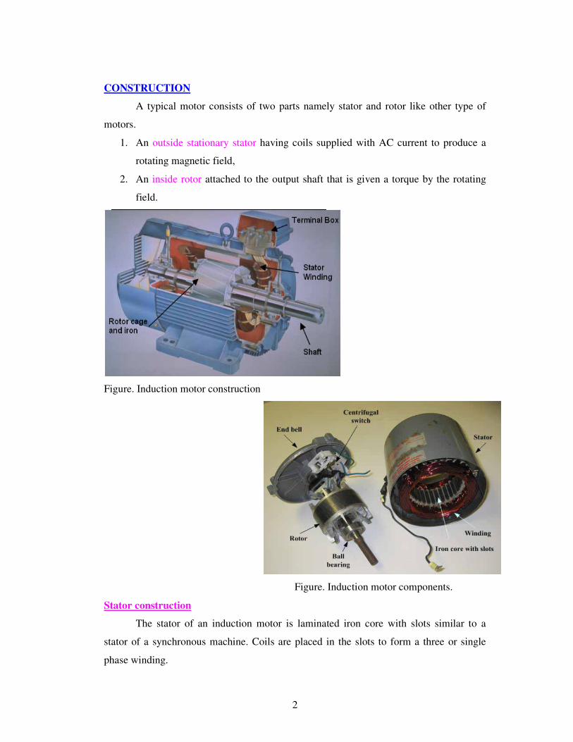
Figure. Induction motor components.
Stator construction
The stator of an induction motor is laminated iron core with slots similar to a
stator of a synchronous machine. Coils are placed in the slots to form a three or single
phase winding.
3
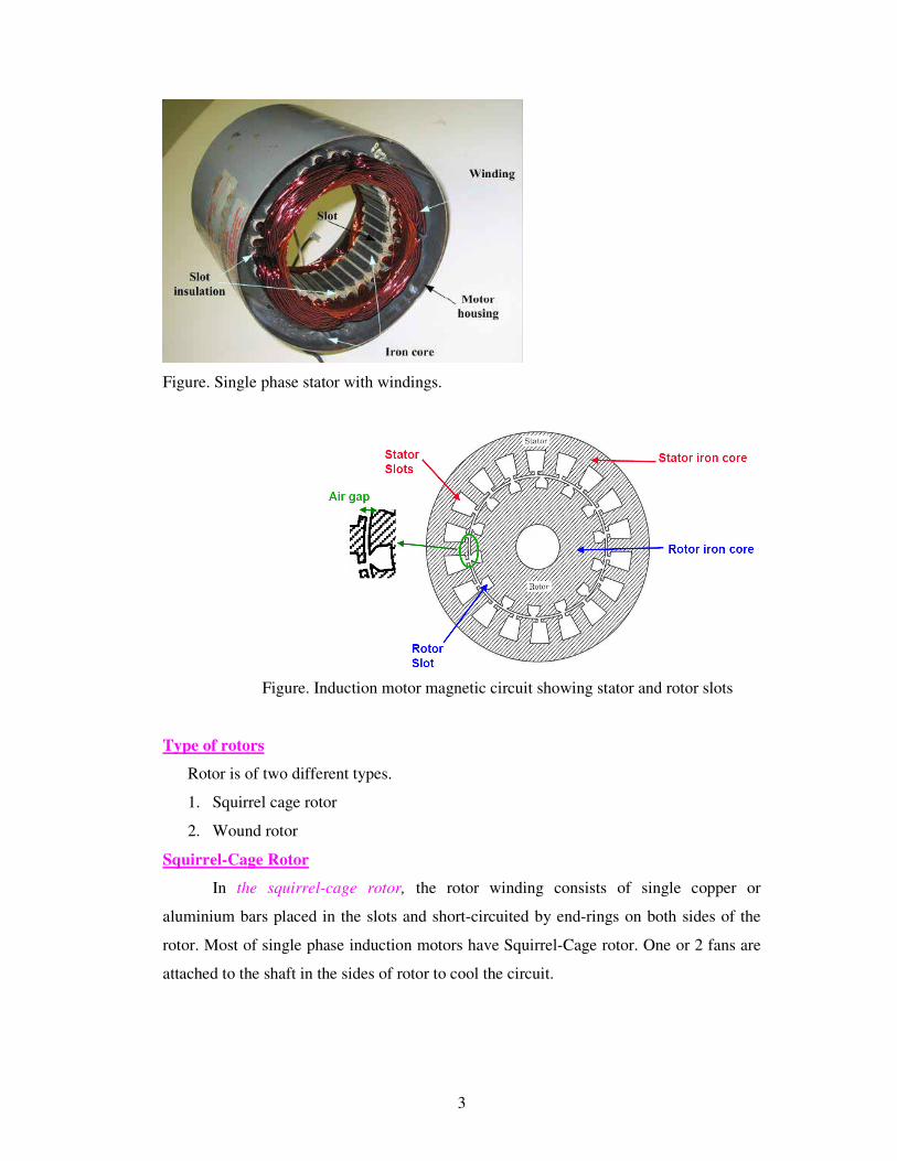
Figure. Single phase stator with windings.
Figure. Induction motor magnetic circuit showing stator and rotor slots
Type of rotors
Rotor is of two different types.
1. Squirrel cage rotor
2. Wound rotor
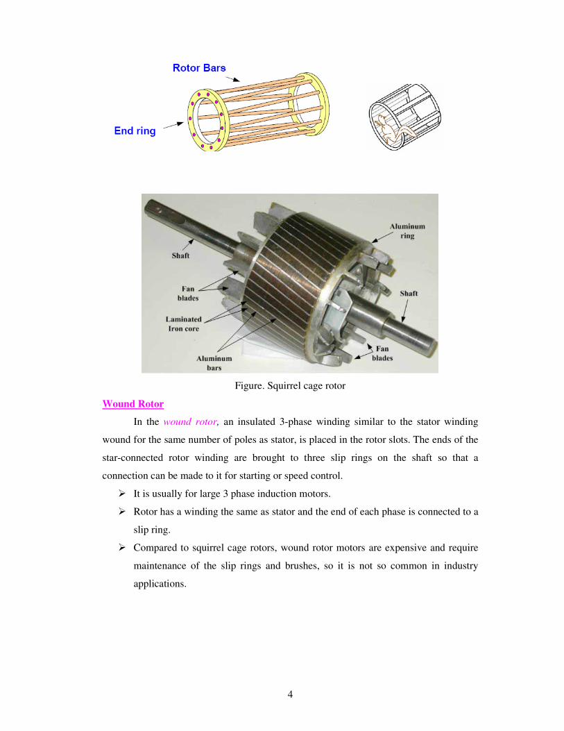
Squirrel-Cage Rotor
In the squirrel-cage rotor, the rotor winding consists of single copper or
aluminium bars placed in the slots and short-circuited by end-rings on both sides of the
rotor. Most of single phase induction motors have Squirrel-Cage rotor. One or 2 fans are
attached to the shaft in the sides of rotor to cool the circuit.
4
Figure. Squirrel cage rotor
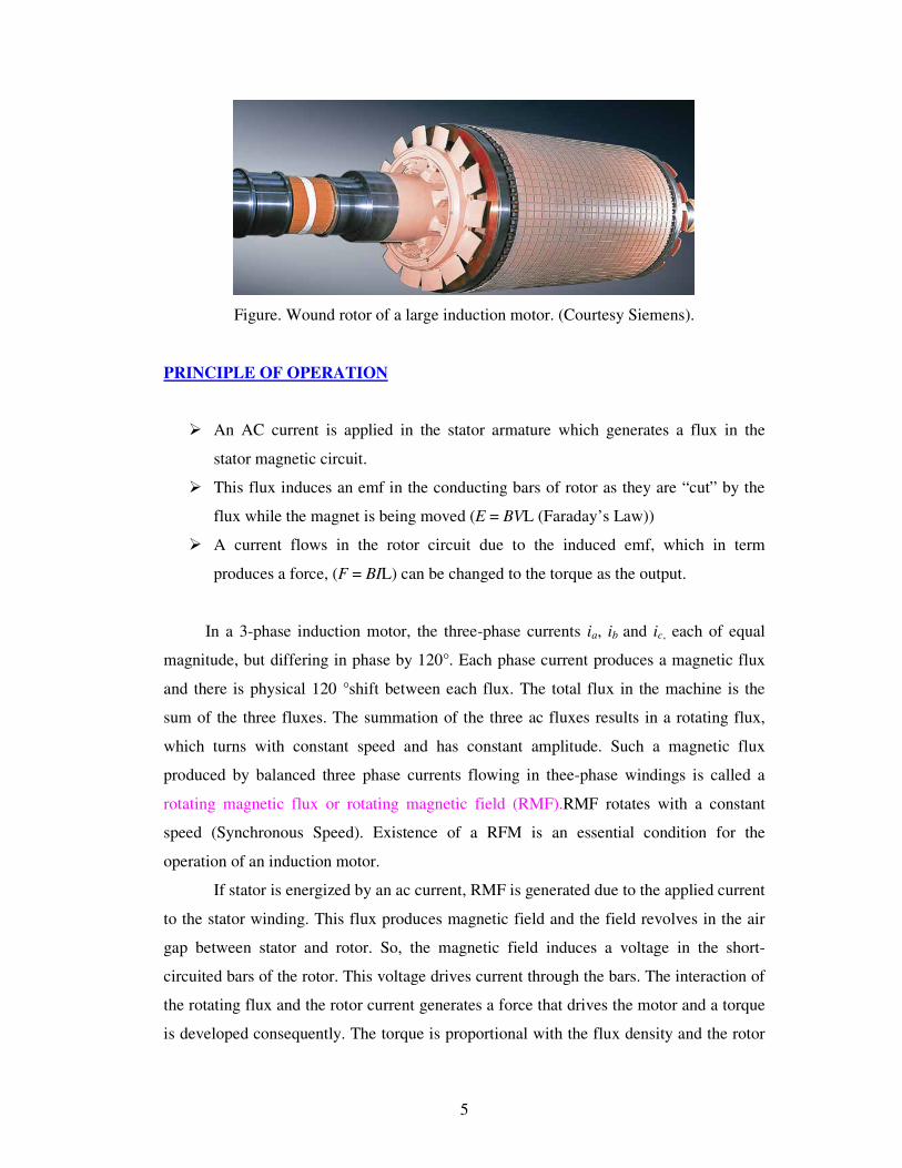
Wound Rotor
In the wound rotor, an insulated 3-phase winding similar to the stator winding
wound for the same number of poles as stator, is placed in the rotor slots. The ends of the
star-connected rotor winding are brought to three slip rings on the shaft so that a
connection can be made to it for starting or speed control.
� It is usually for large 3 phase induction motors.
� Rotor has a winding the same as stator and the end of each phase is connected to a
slip ring.
� Compared to squirrel cage rotors, wound rotor motors are expensive and require
maintenance of the slip rings and brushes, so it is not so common in industry
applications.
5
Figure. Wound rotor of a large induction motor. (Courtesy Siemens).
PRINCIPLE OF OPERATION
� An AC current is applied in the stator armature which generates a flux in the
stator magnetic circuit.
� This flux induces an emf in the conducting bars of rotor as they are “cut” by the
flux while the magnet is being moved (E = BVL (Faraday’s Law))
� A current flows in the rotor circuit due to the induced emf, which in term
produces a force, (F = BIL) can be changed to the torque as the output.
In a 3-phase induction motor, the three-phase currents ia, ib and ic, each of equal
magnitude, but differing in phase by 120°. Each phase current produces a magnetic flux
and there is physical 120 °shift between each flux. The total flux in the machine is the
sum of the three fluxes. The summation of the three ac fluxes results in a rotating flux,
which turns with constant speed and has constant amplitude. Such a magnetic flux
produced by balanced three phase currents flowing in thee-phase windings is called a
rotating magnetic flux or rotating magnetic field (RMF).RMF rotates with a constant
speed (Synchronous Speed). Existence of a RFM is an essential condition for the
operation of an induction motor.
If stator is energized by an ac current, RMF is generated due to the applied current
to the stator winding. This flux produces magnetic field and the field revolves in the air
gap between stator and rotor. So, the magnetic field induces a voltage in the short-
circuited bars of the rotor. This voltage drives current through the bars. The interaction of
the rotating flux and the rotor current generates a force that drives the motor and a torque
is developed consequently. The torque is proportional with the flux density and the rotor
6
bar current (F=BLI). The motor speed is less than the synchronous speed. The direction
of the rotation of the rotor is the same as the direction of the rotation of the revolving
magnetic field in the air gap.
However, for these currents to be induced, the speed of the physical rotor and the
speed of the rotating magnetic field in the stator must be different, or else the magnetic
field will not be moving relative to the rotor conductors and no currents will be induced.
If by some chance this happens, the rotor typically slows slightly until a current is re-
induced and then the rotor continues as before. This difference between the speed of the
rotor and speed of the rotating magnetic field in the stator is called slip. It is unitless and
is the ratio between the relative speed of the magnetic field as seen by the rotor the (slip
speed) to the speed of the rotating stator field. Due to this an induction motor is
sometimes referred to as an asynchronous machine.
SLIP
The relationship between the supply frequency, f, the number of poles, p, and the
synchronous speed (speed of rotating field), ns is given by
120s
fn
p=
The stator magnetic field (rotating magnetic field) rotates at a speed, ns, the
synchronous speed. If, n= speed of the rotor, the slip, s for an induction motor is defined
as
s
s
n ns
n
−=
At stand still, rotor does not rotate , n = 0, so s = 1.
At synchronous speed, n= nS, s = 0
The mechanical speed of the rotor, in terms of slip and synchronous speed is given by,
n=(1-s) ns
Frequency of Rotor Current and Voltage
With the rotor at stand-still, the frequency of the induced voltages and currents is the
same as that of the stator (supply) frequency, fe.
If the rotor rotates at speed of n, then the relative speed is the slip speed:
nslip=ns-n
nslip is responsible for induction.
7
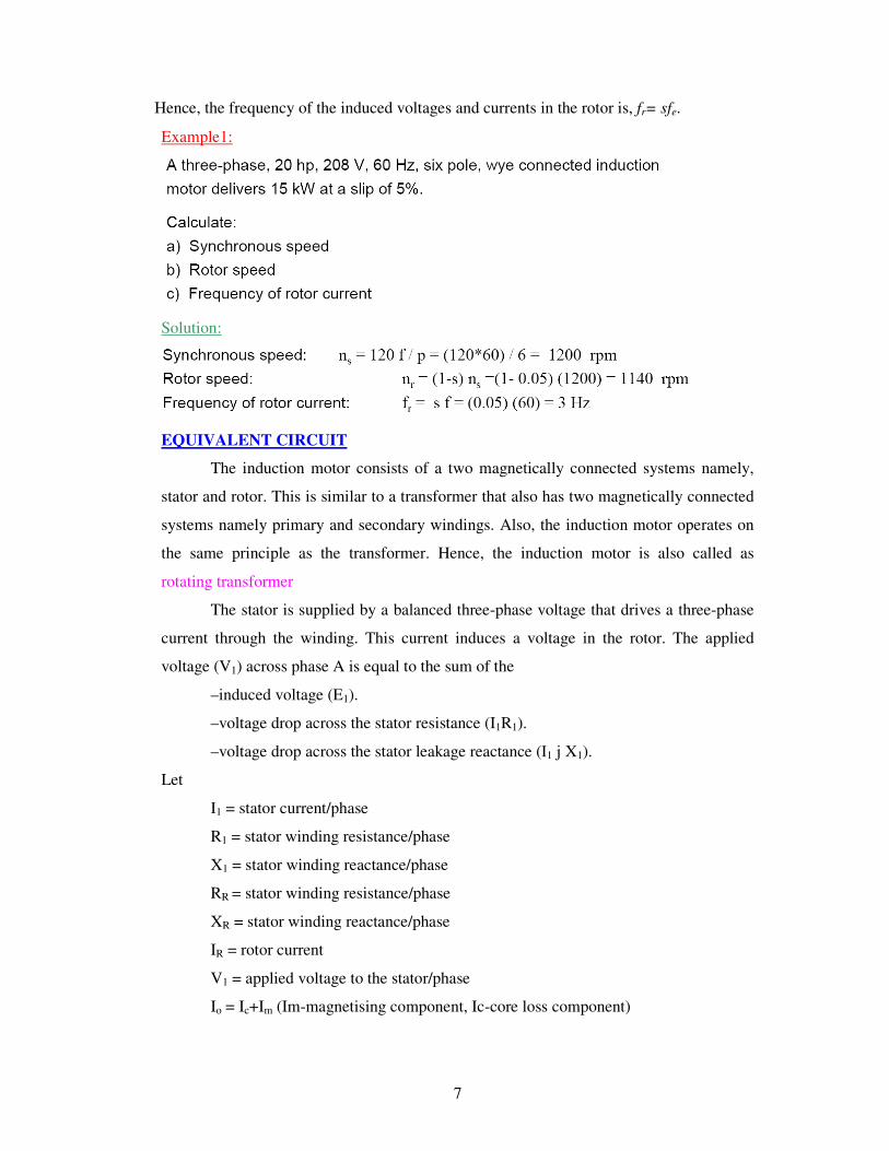
Hence, the frequency of the induced voltages and currents in the rotor is, fr= sfe.
Example1:
Solution:
EQUIVALENT CIRCUIT
The induction motor consists of a two magnetically connected systems namely,
stator and rotor. This is similar to a transformer that also has two magnetically connected
systems namely primary and secondary windings. Also, the induction motor operates on
the same principle as the transformer. Hence, the induction motor is also called as
rotating transformer
The stator is supplied by a balanced three-phase voltage that drives a three-phase
current through the winding. This current induces a voltage in the rotor. The applied
voltage (V1) across phase A is equal to the sum of the
–induced voltage (E1).
–voltage drop across the stator resistance (I1R1).
–voltage drop across the stator leakage reactance (I1 j X1).
Let
I1 = stator current/phase
R1 = stator winding resistance/phase
X1 = stator winding reactance/phase
RR = stator winding resistance/phase
XR = stator winding reactance/phase
IR = rotor current
V1 = applied voltage to the stator/phase
Io = Ic+Im (Im-magnetising component, Ic-core loss component)
8
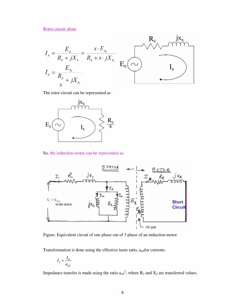
Rotor circuit alone
The rotor circuit can be represented as
So, the induction motor can be represented as
Figure. Equivalent circuit of one phase out of 3 phase of an induction motor
Transformation is done using the effective turns ratio, aefffor currents.
2R
eff
II
a=
Impedance transfer is made using the ratio aeff2; where R2 and X2 are transferred values.
9
R2= aeff2RR
X2= aeff2XR
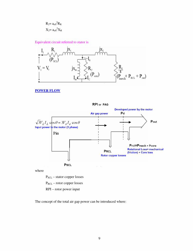
Equivalent circuit referred to stator is
POWER FLOW
where
PSCL – stator copper losses
PRCL – rotor copper losses
RPI – rotor power input
The concept of the total air gap power can be introduced where:
10
The mechanical power however is only developed across the new variable resistance,
hence Pmech is:
As the rotor copper loss is P2 = I22R2 = sPg then a ratio of powers can be defined:
The motor torque is given by
The ideal efficiency can be determined by firstly assuming that the power transferred
across the air gap equals the input power.
Therefore efficiency is given by
The efficiency increases as the speed increases, hence an induction machine
should always be operated at low values of slip to ensure efficient (and high power
factor) operation
TORQUE – SPEED CHARACTERISTICS
For small values of slip s, the torque is directly proportional to s.

11
For large values of slip s, the torque is inversely proportional to s.
Example 2
Solution
12
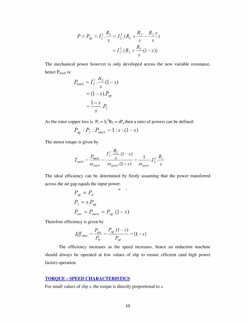
Example 3
Solution:
STARTING OF 3-PHASE INDUCTION MOTORS
There are two important factors to be considered in starting of induction motors:
1. The starting current drawn from the supply, and
2. The starting torque.
The starting current should be kept low to avoid overheating of motor and excessive
voltage drops in the supply network. The starting torque must be about 50 to 100% more
than the expected load torque to ensure that the motor runs up in a reasonably short time.
� At synchronous speed, s = 0, and therefore , 2R
s= ∞ .so I2' = 0.
� The stator current therefore comprises only the magnetising
current i.e. I1 = Iφ and is quite therefore quite small.

13
� At low speeds, 22
'RjX
s+ = ∞ is small, and therefore I2' is quite high and
consequently I1 is quite large.
� Actually the typical starting currents for an induction machine are ~ 5 to 8 times
the normal running current.
Hence the starting currents should be reduced. The most usual methods of starting 3-
phase induction motors are:
For slip-ring motors
� Rotor resistance starting
For squirrel-cage motors
� Direct-on -line starting
� Star-delta starting
� Autotransformer starting.
1. Rotor resistance starting
By adding eternal resistance to the rotor circuit any starting torque up to the
maximum torque can be achieved; and by gradually cutting out the resistance a high
torque can be maintained throughout the starting period. The added resistance also
reduces the starting current, so that a starting torque in the range of 2 to 2.5 times the full
load torque can be obtained at a starting current of 1 to 1.5 times the full load current.
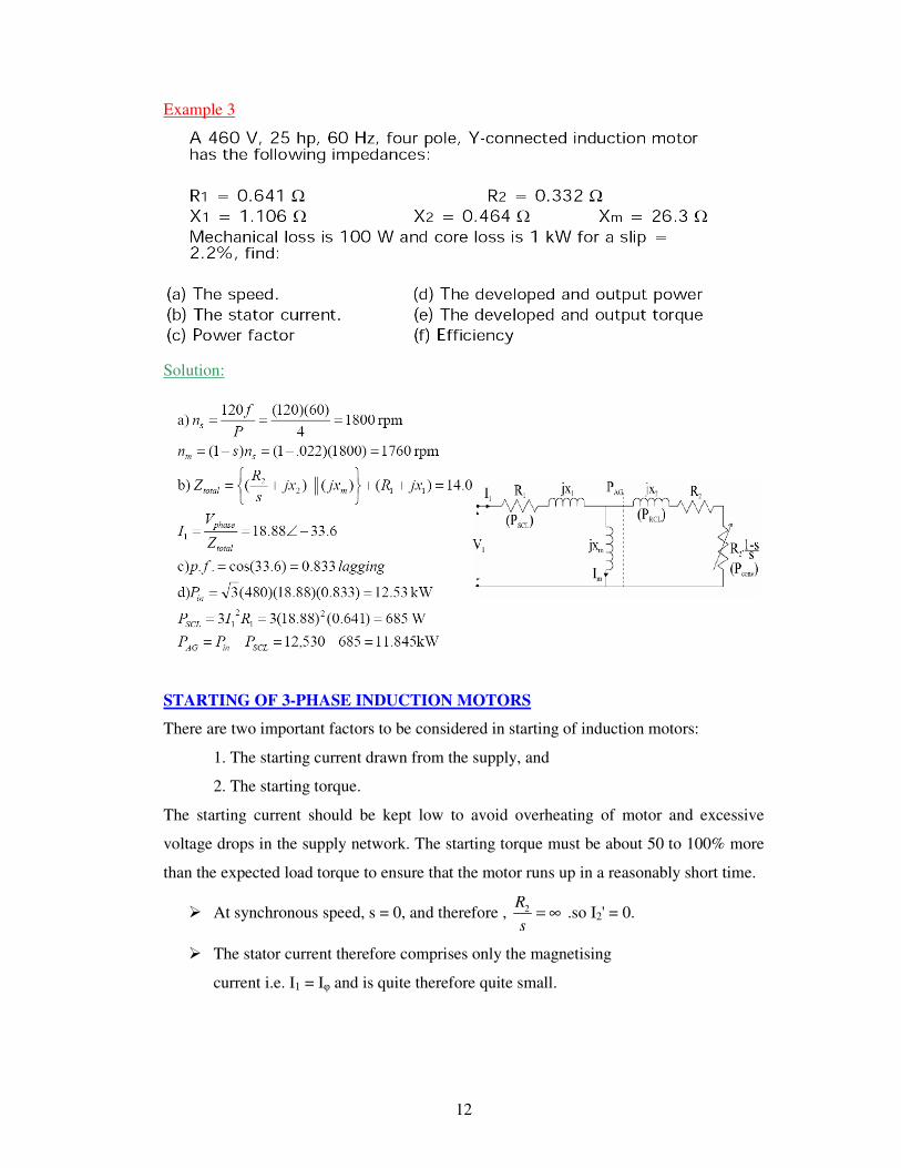
2. Direct-on-line starting
This is the most simple and inexpensive method of starting a squirrel cage
induction motor. The motor is switched on directly to full supply voltage. The initial
starting current is large, normally about 5 to 7 times the rated current but the starting
torque is likely to be 0.75 to 2 times the full load torque. To avoid excessive supply
14
voltage drops because of large starting currents the method is restricted to small motors
only.
To decrease the starting current cage motors of medium and larger sizes are
started at a reduced supply voltage. The reduced supply voltage starting is applied in the
next two methods.
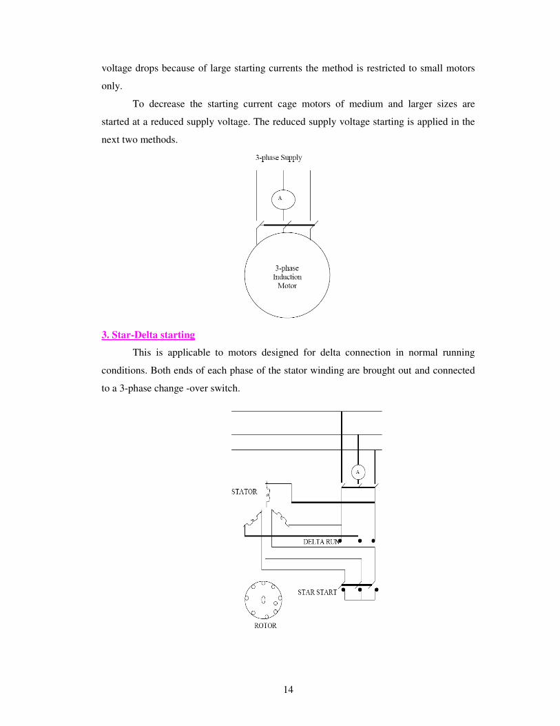
3. Star-Delta starting
This is applicable to motors designed for delta connection in normal running
conditions. Both ends of each phase of the stator winding are brought out and connected
to a 3-phase change -over switch.
15
For starting, the stator windings are connected in star and when the machine is
running the switch is thrown quickly to the running position, thus connecting the motor in
delta for normal operation. The phase voltages & the phase currents of the motor in star
connection are reduced to 1/√3 of the direct -on -line values in delta. The line current is
1/3 of the value in delta.
A disadvantage of this method is that the starting torque (which is proportional to
the square of the applied voltage) is also reduced to 1/3 of its delta value.
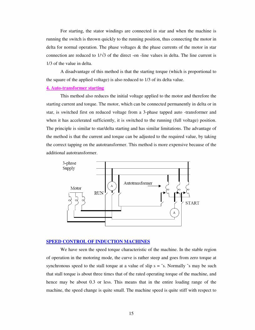
4. Auto-transformer starting
This method also reduces the initial voltage applied to the motor and therefore the
starting current and torque. The motor, which can be connected permanently in delta or in
star, is switched first on reduced voltage from a 3-phase tapped auto -transformer and
when it has accelerated sufficiently, it is switched to the running (full voltage) position.
The principle is similar to star/delta starting and has similar limitations. The advantage of
the method is that the current and torque can be adjusted to the required value, by taking
the correct tapping on the autotransformer. This method is more expensive because of the
additional autotransformer.
SPEED CONTROL OF INDUCTION MACHINES
We have seen the speed torque characteristic of the machine. In the stable region
of operation in the motoring mode, the curve is rather steep and goes from zero torque at
synchronous speed to the stall torque at a value of slip s = ˆs. Normally ˆs may be such
that stall torque is about three times that of the rated operating torque of the machine, and
hence may be about 0.3 or less. This means that in the entire loading range of the
machine, the speed change is quite small. The machine speed is quite stiff with respect to
16
load changes. The entire speed variation is only in the range ns to (1 − s)ns, ns being
dependent on supply frequency and number of poles.
The foregoing discussion shows that the induction machine, when operating from
mains is essentially a constant speed machine. Many industrial drives, typically for fan or
pump applications, have typically constant speed requirements and hence the induction
machine is ideally suited for these. However, the induction machine, especially the
squirrel cage type, is quite rugged and has a simple construction. Therefore it is good
candidate for variable speed applications if it can be achieved.
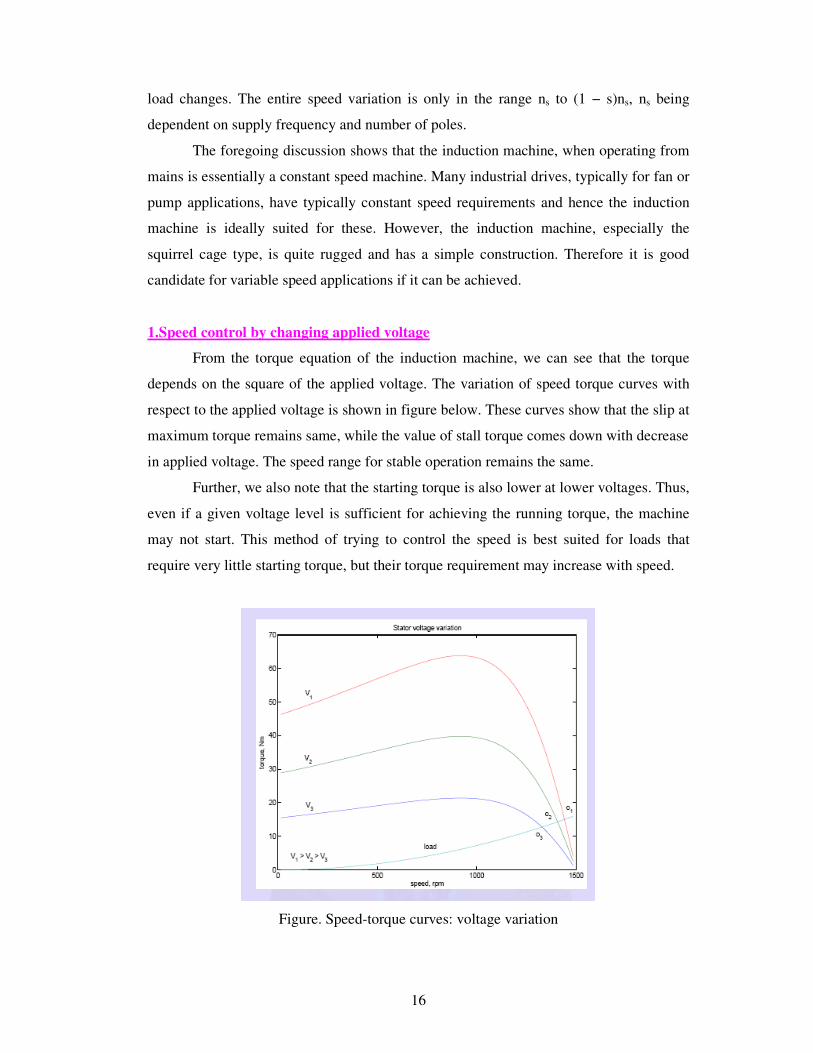
1.Speed control by changing applied voltage
From the torque equation of the induction machine, we can see that the torque
depends on the square of the applied voltage. The variation of speed torque curves with
respect to the applied voltage is shown in figure below. These curves show that the slip at
maximum torque remains same, while the value of stall torque comes down with decrease
in applied voltage. The speed range for stable operation remains the same.
Further, we also note that the starting torque is also lower at lower voltages. Thus,
even if a given voltage level is sufficient for achieving the running torque, the machine
may not start. This method of trying to control the speed is best suited for loads that
require very little starting torque, but their torque requirement may increase with speed.
Figure. Speed-torque curves: voltage variation

17
The figure above also shows a load torque characteristic, one that is typical of a
fan type of load. In a fan (blower) type of load, the variation of torque with speed is such
that T α ω2. Here one can see that it may be possible to run the motor to lower speeds
within the range ns to (1 − s)ns. Further, since the load torque at zero speed is zero, the
machine can start even at reduced voltages. This will not be possible with constant torque
type of loads. One may note that if the applied voltage is reduced, the voltage across the
magnetizing branch also comes down. This in turn means that the magnetizing current
and hence flux level are reduced. Reduction in the flux level in the machine impairs
torque production, which is primarily the explanation for figure.
If, however, the machine is running under lightly loaded conditions, then
operating under rated flux levels is not required. Under such conditions, reduction in
magnetizing current improves the power factor of operation. Some amount of energy
saving may also be achieved. Voltage control may be achieved by adding series resistors
(a lossy, inefficient proposition), or a series inductor / autotransformer (a bulky solution)
or a more modern solution using semiconductor devices. A typical solid state circuit used
for this purpose is the AC voltage controller or AC chopper. Another use of voltage
control is in the so-called ‘soft-start’ of the machine. This is discussed in the section on
starting methods.
2. Rotor resistance control
From the expression for the torque of the induction machine, torque is dependent
on the rotor resistance. The maximum value is independent of the rotor resistance. The
slip at maximum torque is dependent on the rotor resistance. Therefore, we may expect
that if the rotor resistance is changed, the maximum torque point shifts to higher slip
values, while retaining a constant torque. Figure below shows a family of torque-speed
characteristic obtained by changing the rotor resistance.
Note that while the maximum torque and synchronous speed remain constant, the
slip at which maximum torque occurs increases with increase in rotor resistance, and so
does the starting torque. whether the load is of constant torque type or fan-type, it is
evident that the speed control range is more with this method. Further, rotor resistance
control could also be used as a means of generating high starting torque.
For all its advantages, the scheme has two serious drawbacks. Firstly, in order to
vary the rotor resistance, it is necessary to connect external variable resistors (winding
resistance itself cannot be changed). This, therefore necessitates a slip-ring machine,
since only in that case rotor terminals are available outside. For cage rotor machines,
18
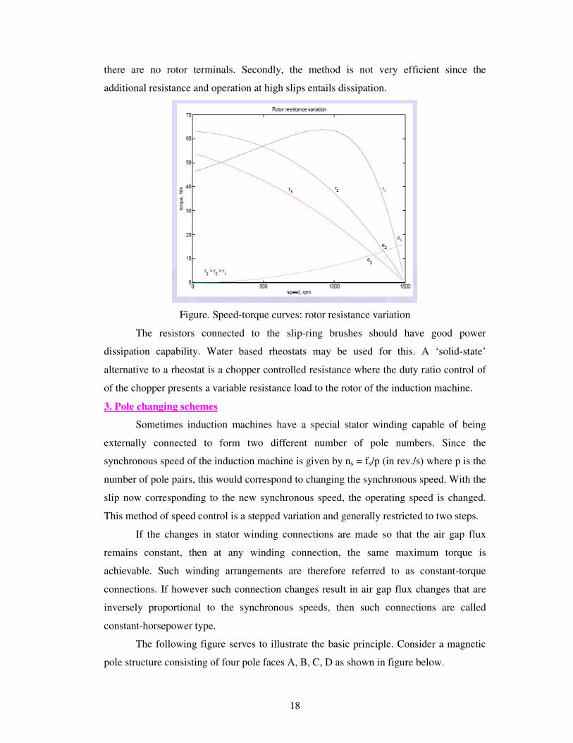
there are no rotor terminals. Secondly, the method is not very efficient since the
additional resistance and operation at high slips entails dissipation.
Figure. Speed-torque curves: rotor resistance variation
The resistors connected to the slip-ring brushes should have good power
dissipation capability. Water based rheostats may be used for this. A ‘solid-state’
alternative to a rheostat is a chopper controlled resistance where the duty ratio control of
of the chopper presents a variable resistance load to the rotor of the induction machine.
3. Pole changing schemes
Sometimes induction machines have a special stator winding capable of being
externally connected to form two different number of pole numbers. Since the
synchronous speed of the induction machine is given by ns = fs/p (in rev./s) where p is the
number of pole pairs, this would correspond to changing the synchronous speed. With the
slip now corresponding to the new synchronous speed, the operating speed is changed.
This method of speed control is a stepped variation and generally restricted to two steps.
If the changes in stator winding connections are made so that the air gap flux
remains constant, then at any winding connection, the same maximum torque is
achievable. Such winding arrangements are therefore referred to as constant-torque
connections. If however such connection changes result in air gap flux changes that are
inversely proportional to the synchronous speeds, then such connections are called
constant-horsepower type.
The following figure serves to illustrate the basic principle. Consider a magnetic
pole structure consisting of four pole faces A, B, C, D as shown in figure below.

19
Figure. Pole arrangement
Coils are wound on A & C in the directions shown. The two coils on A & C may be
connected in series in two different ways — A2 may be connected to C1 or C2. A1 with
the other terminal at C then form the terminals of the overall combination. Thus two
connections result as shown in figure (a) & (b) below.
Now, for a given direction of current flow at terminal A1, say into terminal A1, the
flux directions within the poles are shown in the figures. In case (a), the flux lines are out
of the pole A (seen from the rotor) for and into pole C, thus establishing a two-pole
structure. In case (b) however, the flux lines are out of the poles in A & C. The flux lines
will be then have to complete the circuit by flowing into the pole structures on the sides.
If, when seen from the rotor, the pole emanating flux lines is considered as north pole and
the pole into which they enter is termed as south, then the pole configurations produced
by these connections is a two-pole arrangement in fig. 31(a) and a four-pole arrangement
in fig. 31(b). Thus by changing the terminal connections we get either a two pole air-gap
field or a four-pole field. In an induction machine this would correspond to a synchronous
speed reduction in half from case (a) to case (b).

20
Figure: Pole Changing: Various connections
Further note that irrespective of the connection, the applied voltage is balanced by the
series addition of induced emfs in two coils. Therefore the air-gap flux in both cases is
the same. Cases (a) and (b) therefore form a pair of constant torque connections.
Consider, on the other hand a connection as shown in the figure(c). The terminals
T1 and T2 are where the input excitation is given. Note that current direction in the coils
now resembles that of case (b), and hence this would result in a four-pole structure.
However, in figure(c), there is only one coil induced emf to balance the applied voltage.
Therefore flux in case (c) would therefore be halved compared to that of case (b) (or case
(a), for that matter). Cases (a) and (c) therefore form a pair of constant horse-power
connections. It is important to note that in generating a different pole numbers, the current
through one coil (out of two, coil C in this case) is reversed.
4. Stator frequency control
The expression for the synchronous speed indicates that by changing the stator
frequency also it can be changed. This can be achieved by using power electronic circuits
called inverters which convert dc to ac of desired frequency. Depending on the type of
control scheme of the inverter, the ac generated may be variable-frequency-fixed-
amplitude or variable-frequency variable-amplitude type. Power electronic control
achieves smooth variation of voltage and frequency of the ac output. This when fed to the
machine is capable of running at a controlled speed. However, consider the equation for
the induced emf in the induction machine.
V = 4.44NØmf
where N is the number of the turns per phase, _m is the peak flux in the air gap and f is
the frequency. Note that in order to reduce the speed, frequency has to be reduced. If the
frequency is reduced while the voltage is kept constant, thereby requiring the amplitude
of induced emf to remain the same, flux has to increase. This is not advisable since the
21
machine likely to enter deep saturation. If this is to be avoided, then flux level must be
maintained constant which implies that voltage must be reduced along with frequency.
The ratio is held constant in order to maintain the flux level for maximum torque
capability.
Actually, it is the voltage across the magnetizing branch of the exact equivalent
circuit that must be maintained constant, for it is that which determines the induced emf.
Under conditions where the stator voltage drop is negligible compared the applied
voltage, the above equation is valid.
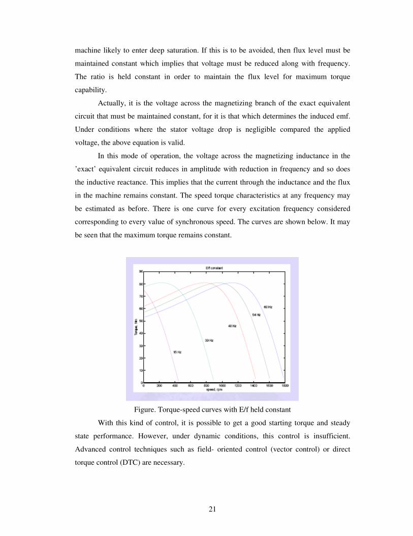
In this mode of operation, the voltage across the magnetizing inductance in the
’exact’ equivalent circuit reduces in amplitude with reduction in frequency and so does
the inductive reactance. This implies that the current through the inductance and the flux
in the machine remains constant. The speed torque characteristics at any frequency may
be estimated as before. There is one curve for every excitation frequency considered
corresponding to every value of synchronous speed. The curves are shown below. It may
be seen that the maximum torque remains constant.
Figure. Torque-speed curves with E/f held constant
With this kind of control, it is possible to get a good starting torque and steady
state performance. However, under dynamic conditions, this control is insufficient.
Advanced control techniques such as field- oriented control (vector control) or direct
torque control (DTC) are necessary.

22
SINGLE-PHASE INDUCTION MOTORS
There are probably more single-phase ac induction motors in use today than the
total of all the other types put together.
It is logical that the least expensive, lowest maintenance type of ac motor should
be used most often. The single-phase ac induction motor fits that description.
Unlike polyphase induction motors, the stator field in the single-phase motor does
not rotate. Instead it simply alternates polarity between poles as the ac voltage changes
polarity.
Voltage is induced in the rotor as a result of magnetic induction, and a magnetic
field is produced around the rotor. This field will always be in opposition to the stator
field (Lenz's law applies). The interaction between the rotor and stator fields will not
produce rotation, however. The interaction is shown by the double-ended arrow in figure
below, view A. Because this force is across the rotor and through the pole pieces, there is
no rotary motion, just a push and/or pull along this line.
Figure. Rotor currents in a single-phase ac induction motor.
Now, if the rotor is rotated by some outside force (a twist of your hand, or
something), the push-pull along the line in figure 4-10, view A, is disturbed. Look at the
fields as shown in figure, view B. At this instant the south pole on the rotor is being

23
attracted by the left-hand pole. The north rotor pole is being attracted to the right-hand
pole. All of this is a result of the rotor being rotated 90° by the outside force. The pull that
now exists between the two fields becomes a rotary force, turning the rotor toward
magnetic correspondence with the stator. Because the two fields continuously alternate,
they will never actually line up, and the rotor will continue to turn once started. It remains
for us to learn practical methods of getting the rotor to start.
There are several types of single-phase induction motors in use today. Basically
they are identical except for the means of starting. In this chapter we will discuss the
split-phase and shaded-pole motors; so named because of the methods employed to get
them started. Once they are up to operating speed, all single-phase induction motors
operate the same.
Split-Phase Induction Motors
One type of induction motor, which incorporates a starting device, is called a
split-phase induction motor. Split-phase motors are designed to use inductance,
capacitance, or resistance to develop a starting torque. The principles are those that you
learned in your study of alternating current.
Capacitor-Start Single Phase Induction Motor
The first type of split-phase induction motor that will be covered is the capacitor-
start type. figure below shows a simplified schematic of a typical capacitor-start motor.
The stator consists of the main winding and a starting winding (auxiliary). The starting
winding is connected in parallel with the main winding and is placed physically at right
angles to it. A 90-degree electrical phase difference between the two windings is obtained
by connecting the auxiliary winding in series with a capacitor and starting switch. When
the motor is first energized, the starting switch is closed. This places the capacitor in
series with the auxiliary winding.
The capacitor is of such value that the auxiliary circuit is effectively a resistive-
capacitive circuit (referred to as capacitive reactance and expressed as XC). In this circuit
the current leads the line voltage by about 45° (because XC about equals R). The main
winding has enough resistance-inductance (referred to as inductive reactance and

24
expressed as XL) to cause the current to lag the line voltage by about 45° (because XL
about equals R). The currents in each winding are therefore 90° out of phase - so are the
magnetic fields that are generated. The effect is that the two windings act like a two-
phase stator and produce the rotating field required to start the motor.
Figure. Capacitor-start, ac induction motor.
When nearly full speed is obtained, a centrifugal device (the starting switch) cuts
out the starting winding. The motor then runs as a plain single-phase induction motor.
Since the auxiliary winding is only a light winding, the motor does not develop sufficient
torque to start heavy loads. Split-phase motors, therefore, come only in small sizes.
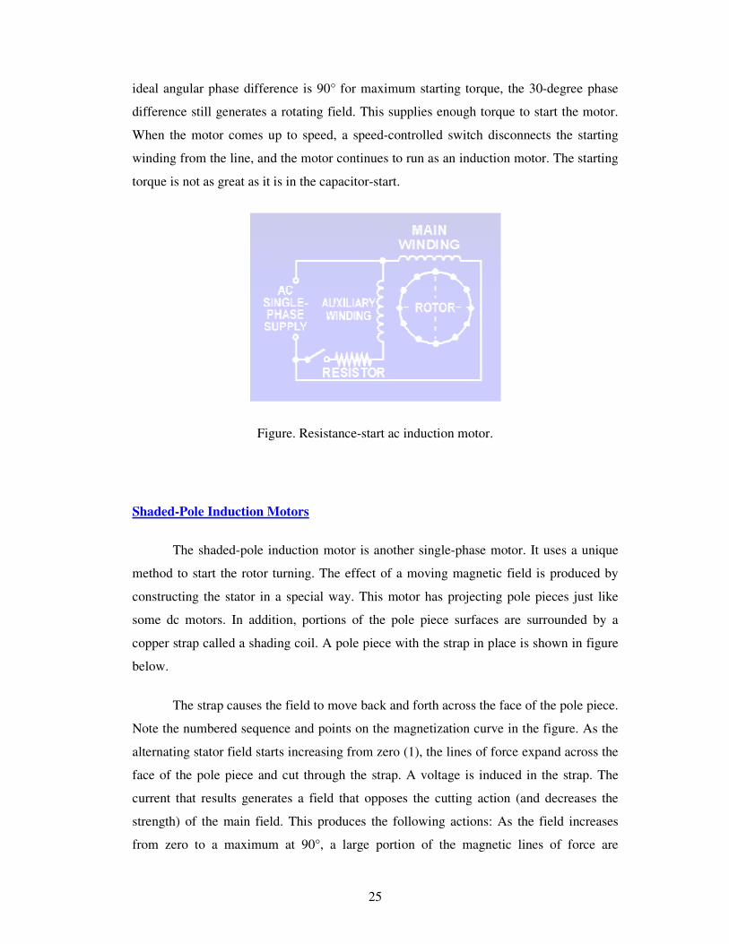
Resistance Start Single Phase Induction Motor
Another type of split-phase induction motor is the resistance-start motor. This
motor also has a starting winding figure in addition to the main winding. It is switched in
and out of the circuit just as it was in the capacitor-start motor. The starting winding is
positioned at right angles to the main winding. The electrical phase shift between the
currents in the two windings is obtained by making the impedance of the windings
unequal.
The main winding has a high inductance and a low resistance. The current,
therefore, lags the voltage by a large angle. The starting winding is designed to have a
fairly low inductance and a high resistance. Here the current lags the voltage by a smaller
angle. For example, suppose the current in the main winding lags the voltage by 70°. The
current in the auxiliary winding lags the voltage by 40°. The currents are, therefore, out of
phase by 30°. The magnetic fields are out of phase by the same amount. Although the
25
ideal angular phase difference is 90° for maximum starting torque, the 30-degree phase
difference still generates a rotating field. This supplies enough torque to start the motor.
When the motor comes up to speed, a speed-controlled switch disconnects the starting
winding from the line, and the motor continues to run as an induction motor. The starting
torque is not as great as it is in the capacitor-start.
Figure. Resistance-start ac induction motor.
Shaded-Pole Induction Motors
The shaded-pole induction motor is another single-phase motor. It uses a unique
method to start the rotor turning. The effect of a moving magnetic field is produced by
constructing the stator in a special way. This motor has projecting pole pieces just like
some dc motors. In addition, portions of the pole piece surfaces are surrounded by a
copper strap called a shading coil. A pole piece with the strap in place is shown in figure
below.
The strap causes the field to move back and forth across the face of the pole piece.
Note the numbered sequence and points on the magnetization curve in the figure. As the
alternating stator field starts increasing from zero (1), the lines of force expand across the
face of the pole piece and cut through the strap. A voltage is induced in the strap. The
current that results generates a field that opposes the cutting action (and decreases the
strength) of the main field. This produces the following actions: As the field increases
from zero to a maximum at 90°, a large portion of the magnetic lines of force are

26
concentrated in the unshaded portion of the pole (1). At 90° the field reaches its
maximum value. Since the lines of force have stopped expanding, no emf is induced in
the strap, and no opposing magnetic field is generated. As a result, the main field is
uniformly distributed across the pole (2). From 90° to 180°, the main field starts
decreasing or collapsing inward. The field generated in the strap opposes the collapsing
field. The effect is to concentrate the lines of force in the shaded portion of the pole face
(3). You can see that from 0° to 180°, the main field has shifted across the pole face from
the unshaded to the shaded portion. From 180° to 360°, the main field goes through the
same change as it did from 0° to 180°; however, it is now in the opposite direction (4).
The direction of the field does not affect the way the shaded pole works. The motion of
the field is the same during the second half-cycle as it was during the first half of the
cycle.
Figure. Shaded poles as used in shaded-pole ac induction motors.
The motion of the field back and forth between shaded and unshaded portions
produces a weak torque to start the motor. Because of the weak starting torque, shaded-
pole motors are built only in small sizes. They drive such devices as fans, clocks,
blowers, and electric razors.
SUMMARY
In this chapter, construction and working of 3-phase induction motor has been
discussed. The induction motor rotates at a speed less than the synchronous speed and
also called asynchronous motor. The difference between the synchronous speed and the

27
rotor speed is the slip speed. Various configuration of the equivalent circuit have been
analysed. A general expression for torque has been derived, which is used to plot the
torque-slip characteristics of the motor. Various methods of starting and speed control are
also discussed. The working principle and types of single phase induction motors have
also been discussed.
Short answer questions
1. Why are 3-phase induction motors very popular as drives for industrial applications?
2. What are the various types of 3-phase induction motors as per the rotor construction?
3. List the differences between squirrel cage and slip ring rotor.
4. Define slip of induction motor.
5. A 3-phase induction motor does not run at synchronous speed. Why?
6. Why is the no-load current drawn by 3-phase induction motor so high?
7. Compare the efficiency and operating power factor of single phase induction motor
with 3-phase induction motor.
8. Why single phase induction motors are not self-starting?
9. What are the various types of single phase induction motors?
10. How to change the direction of induction motor?
Detailed answer questions
1. With the help of diagrams, explain how a rotating magnetic field is produced in the
air gap of a 3-phase induction motor.
2. Explain the principle of operation of 3-phase induction motor.
3. Derive the relationship between the rotor copper losses and the rotor input in a 3-
phase induction motor .
4. Explain the effect of slip on the following rotor parameters.
i) frequency ii) induced emf iii) current iv) power factor v)reactance
5. Derive a general expression for the torque developed in a 3-phase induction motor.
6. Sketch and explain the torque-speed characteristics of a 3-phase induction motor.
7. List the various losses that take place in an induction motor.
8. Draw and explain the phasor diagram of a 3-phase induction motor.
9. Develop the equivalent of a 3-phase induction motor.
10. i)Why do we need a starter for starting a 3-phase induction motor?

28
ii) Draw a neat diagram showing the connections of 3-phase induction motor with
star-delta starter. Explain how the above starter reduces the starting current.
11. Draw the diagram of an auto-transformer starter used for 3-phase induction motor and
explain its operation.
12. Describe the no-load test and blocked rotor test to determine the parameters of
equivalent circuit of 3-phase induction motor.
13. Explain the various techniques used for speed control of 3-phase induction motor.
14. Explain rotor resistance speed control of 3-phase induction motor.
15. Explain the double field revolving theory.
16. Draw and explain the equivalent circuit of a single phase induction motor based on
double field revolving theory.
Related Documents