FABTECH College of Engineering and Research, Sangola UNIT 2 UNIT – 2 Moulding and Core making processes • Green Moulding sand, its ingredients and properties, facing sand, backing sand, unit sand, natural moulding sand, shell sand, CO2 sand. • Oil sand cores, and core making, CO2 core making, shell core making, cold box process of core making. • Green sand moulding (hand and machine moulding), shell moulding, CO 2 process. • Introduction to special casting techniques, such as Investment casting, centrifugal casting, continuous casting, gravity and pressure die casting processes. MOULDING PROCESSES Moulding processes in common use may be classified according to different forms. They may broadly be classified as: (1) Hand moulding (2) Machine moulding. In piece and, small-lot production foundry practice, sand moulds are made by hand; moulding machines are employed in large-lot and mass production. Moulding processes are often classified according to (1) The type of material of which the mould is made (a) Green sand moulds (b) Dry sand moulds (c) Skin-dried moulds, (d) Loam moulds (2) The methods used in making the mould (a) Bench moulding (b) Floor moulding (c) Pit moulding (d) Sweep moulding (e) Plate moulding. Principal ingredients of Moulding sand: The principal ingredients of moulding sands are: (1) Silica sand grains (2) Clay (3) Moisture (4) Miscellaneous materials (1) Silica sand grains: Silica in the form of granular quartz, itself a sand, is the chief constituent of moulding sand. Silica sand contains from 80 to 90 per cent Manufacturing Processes Prepared by: Prof. S.C. Kulkarni & Jay Gawade Page 28

Unit 2 Notes
Dec 29, 2015
sdhhjdf
Welcome message from author
This document is posted to help you gain knowledge. Please leave a comment to let me know what you think about it! Share it to your friends and learn new things together.
Transcript

FABTECH College of Engineering and Research, Sangola UNIT 2
UNIT – 2 Moulding and Core making processes• Green Moulding sand, its ingredients and properties, facing sand, backing sand, unit sand, natural moulding sand, shell sand, CO2 sand.• Oil sand cores, and core making, CO2 core making, shell core making, cold box process of core making.• Green sand moulding (hand and machine moulding), shell moulding, CO2 process.• Introduction to special casting techniques, such as Investment casting, centrifugal casting, continuous casting, gravity and pressure die casting processes.
MOULDING PROCESSESMoulding processes in common use may be classified according to different forms. They may broadly be classified as: (1) Hand moulding (2) Machine moulding. In piece and, small-lot production foundry practice, sand moulds are made by hand; moulding machines are employed in large-lot and mass production.
Moulding processes are often classified according to
(1) The type of material of which the mould is made
(a) Green sand moulds (b) Dry sand moulds (c) Skin-dried moulds, (d) Loam moulds
(2) The methods used in making the mould
(a) Bench moulding (b) Floor moulding (c) Pit moulding (d) Sweep moulding (e) Plate moulding.
Principal ingredients of Moulding sand:The principal ingredients of moulding sands are: (1) Silica sand grains (2) Clay (3) Moisture (4) Miscellaneous materials(1) Silica sand grains: Silica in the form of granular quartz, itself a sand, is the
chief constituent of moulding sand. Silica sand contains from 80 to 90 per cent
silicon dioxide and is characterized by a high softening temperature and thermal
stability. It is a product of the breaking up of quartz rocks or the decomposition of
granite, which is composed of quartz and feldspar. The feldspar, when decomposed,
becomes clay (hydrous aluminium silicate). However, silica sand grains impart
refractoriness, chemical resistivity, and permeability to the sand. They are specified
according to their average size and shape.
(2) Clay: Clay is defined as those particles of sand (under 20 microns in
diameter) that fail to settle at a rate of 25 mm per minute, when suspended in water.
Clay consists of two ingredients: fine silt and true clay. Fine silt is a sort of foreign
matter or mineral deposit and has no bonding power. It is the true clay which imparts
the necessary bonding strength to the mould sand, so that the mould does not lose its
shape after ramming. True clay is found to be made up of extremely minute aggregates of
crystalline, usually flake-shaped, particles called clay minerals. Most moulding
sands for different grades of work contain 5 to 20 per cent clay.
Manufacturing Processes Prepared by: Prof. S.C. Kulkarni & Jay Gawade Page 28
FABTECH College of Engineering and Research, Sangola UNIT 2
(3) Moisture: Moisture, in requisite amount, furnishes the bonding action of clay. When water is added to clay, it penetrates the mixture and forms a microfilm which coats the surface of flake-shaped clay particles. The bonding quality of clay depends on the maximum thickness of water film it can maintain. The bonding action •is considered best if the water added is the exact quantity required to form the film. On the other hand, the bonding action is reduced and the mould gets weakened if the water is in excess. The water should be between 2 and 8 per cent.(4) Miscellaneous materials: Miscellaneous materials that are found, in addition to silica and clay, in moulding sand are oxide of iron, limestone, magnesia, soda, and potash. The impurities should be below 2 per cent.Moulding sands may be classified generally into three different types:
(1)Natural moulding sands (2) Synthetic or high silica sands (3) Special sands.
Natural moulding sands, called green sands, are taken from rivers beds or are dug from
pits. They possess an appreciable amount of clay which acts as a bond between the sand
grains and are used as received with water added. The quantity and type of clay mineral
present affect the strength, toughness and refractoriness of the sand. Natural moulding
sands are also obtained by crushing and milling soft yellow sandstone, carboniferous
rocks, etc. During the milling operation, clay aggregates break down and clay particles get
uniformly distributed over the sand grains. The grain shape of these sands is required to be
sub angular to round.
Due to their ease of availability, low cost, and high flexibility of operation natural moulding
sands are used for most of the ferrous and nonferrous light castings.
Synthetic sands are basically high silica sands containing little (less than 2 per cent) or no
binder (clay) in natural form. They occur as loose or poorly consolidated deposits of
sedimentary origin, dunes blown inland from the coast or accumulated deposits in rivers
along the coast. They are also made in foundry by first crushing quartzite sandstones and
then washing and grading these to yield a sand grade of requisite shape and grain distribution.
The desired strength and bonding properties of these sands are developed by separate
additions such as bentonite, water and other materials. This allows greater flexibilities in
the content of properties such as green and dry strength, permeability and others that can be
easily varied at will. Therefore, synthetic sands are more expensive than natural sands.
Special sands are ideal in getting special characteristics which are not ordinarily obtained in other sands. Zircon, olivine, chamottee, chromite & chrome magnesite are often used in special sands.
MAIN CONSTITUENTS OF MOULDING SAND
The principal constituents of moulding sand are:
1. Silica sand 2. Binder3. Additives 4. Water
Manufacturing Processes Prepared by: Prof. S.C. Kulkarni & Jay Gawade Page 29

FABTECH College of Engineering and Research, Sangola UNIT 2
2. BINDERS
The purpose of adding a binder to the moulding sand is to impart it sufficient strength and
cohesiveness so as to enable it to retain i ts shape af ter the mould has been rammed
and the pat tern withdrawn. However, it produces an adverse effect on the permeability of the
sand mould. The common binders used in foundry can be g rouped as:
1. Organic binders. 2. Inorganic binders.
Organic Binders find their specific use in core making. The common binders coming in this category are: (i) Dextrin (ii) Molasses
(ii) Linseed oil (iv) Cereal binders(v) Pitch—upto 2% max. (vi) Resins, like phenol and urea formaldehydes.
In the Inorganic group the common binders are clay, sodium silicate and Portland cement. Out of all these, the clay binders are commonly used. The following types of clays are commonly used:
(i) Bentonite (ii) Kaolonite(iii) Limonite (iv) Ball clay
(v) Fire clay (vi) Fuller's earth.Out of the above six varieties Bentonite is most widely used in our country.Its deposits
are found in Bihar, Rajasthan and Jammu Kashmir.
3. ADDITIVES
Additives are those materials which are added to the moulding sand to improve upon some of its existing properties or to impart certain new properties to it. The commonly used additives are: a) Coal Dust: It is mainly used in the sand used for grey iron and malleable iron castings. Its main purpose is to react chemically with the oxygen present in the sand pores and, thus, produce a reducing atmosphere at mould-metal interface and prevent oxidation of the metal. For this reason its major portion is added in the facing sand. It, however reduces the cohesiveness and strength of the sand.b) Sea Coal: It is a finely ground soft coal and is vastly used in sands used for grey and malleable iron castings. It restricts the mould wall movement and improves surface finish. It reduces permeability and hot strength of the mould and requires a higher percentage of water in the sand. Its proportion varies from 2 to 8 percent.c) Cereals or Cornflour: It promotes mould wall movement by being volatized by heat, reduces expansion defects, and improves strength, toughness and collapsibility of the sand and decreases permeability and flowability. Its proportion in the sand varies from 0.25 to 2.0 percent.d) Silica Floor: It increases hot strength, decreases metal penetration into the mould, reduces expansion defects and improves surface finish. It may be added upto 35 percent.e) Wood Flour: It promotes mould wall movement, reduces expansion defects, increases collapsibility, and improves surface finish and thermal stability of mould. It may be added from 0.5 to 2.0 percent or even more.
Manufacturing Processes Prepared by: Prof. S.C. Kulkarni & Jay Gawade Page 30

FABTECH College of Engineering and Research, Sangola UNIT 2
f) Pitch: It improves hot strength and surface finish on ferrous castings. It can be advantageously added upto 2.0 percent. If a higher proportion is added it will reduce green strength.
g) Dextrin and Mollases: Their addition increases the dry- strength of the sand. In other respects they behave more or less likecornflour.h) Fuel Oil: Its addition is sometimes done in order to reduce the requirement of free water in the sand.4. WATERThe clay content added to the foundry sand will not give the required strength and bond until a
suitable quantity of water is added to it. This quantity of water varies from 2 to 8 percent
according to different requirements.
The water content present in the sand mass is partly in mixed form, called pore water,
and partly in the free state, known as free water. When water is added to the clay it starts
filling into the pores of the clay, where it forms a sort of micro-film. This water content
is held rigidly by the clay and it is mainly responsible for enabling the clay to impart the
desired strength to the sand. The quantity of bond and the capacity of clay for providing the
bond will mainly depend upon the thickness of the water film that it can hold.
When more water is added to the clay mixture, than the amount required as pore water, it
remains as a fluid and is held between the clay particles separating them. It has been found
that this excess amount of free water behaves as a lubricant and, thus, improves the
mouldability and plasticity of the moulding sand. It however, reduces the strength of the
mixture and, thus, weakens the mould.
MOULDING PROCESSES BASED ON SAND USEDGREEN-SAND MOULDGreen-sand moulds are prepared with natural moulding sands or with mixtures of silica sand, bonding clay, and water. These materials are thoroughly mixed in proportions which will give the desired properties for the class of work being done. To make the green-sand mould the sand must be properly tempered before it can be used. If the sand is too dry, additional water is added if too wet, dry sand is added until it has the proper temper. To check the sand for proper temper, a handful is grasped in the first. The pressure is released, and the sand is broken in two sections. The sections of sand should retain their shape and the edges of the break should be sharp and firm.The surface of the mould which comes in contact with the molten metal forms the most important part in green-sand moulds. In order to give the casting a clean and bright surface and to prevent the sand from burningGreen sand and its ingredients:-The sand in its naturla or moist state is called green sand. It is also called tempered sand. It is a mixture of silica sand with 20 to 30 % clay, having total amount of water from 6 to 10%. The moulds prepared with this sand are called green sand molds. The molten metal is poured in the green sand molds without any prior baking. The green sand molds are used for small size castings of ferrous and non-ferrous molds.
Manufacturing Processes Prepared by: Prof. S.C. Kulkarni & Jay Gawade Page 31

FABTECH College of Engineering and Research, Sangola UNIT 2
TYPES OF MOULDING SAND
Moulding sands can be classified, according to their use, into a number of varieties. Types of Moulding sand are described follow:1. Green sand:It is a mixture of silica sand with 18 to 30 per cent clay, having a total water of from 6 to 8 per cent. The clay and water furnish the bond for green sand. It is fine, soft, light, and porous. Being damp, when squeezed in the hand, it retains the shape, the impression given to it under pressure. Moulds prepared in this sand are known as green sand moulds.2. Natural sand:-The natural sand is one which contains sufficient clay as mined from the sand pit so that it can be used directly. It needs only to be tempered and conditioned. Since the natural sand have the advantages of simplicity in their preparation, handling in use, therefore these are used for most of the ferrous and non-ferrous castings.3. Dry sand:Green sand that has been dried or baked after the mould is made is called dry sand. They are suitable for larger castings. Moulds prepared in this sand are known as dry sand moulds.4. Loam sand: Loam sand is high in clay, as much as 50 per cent or so, and dries hard. This is particularly employed for loam moulding usually for large castings.5. Facing sand: Facing sand forms the face of the mould. It is used directly next to the surface of the pattern and it comes into contact with the molten metal when the mould is poured. It is subjected to the severest conditions and must possess, therefore, high strength and refractoriness. It is made of silica sand and clay, without the addition of used sand. Different forms of carbon are used to prevent the metal from burning into the sand. They are sometimes mixed with 6 to 15 times as much fine moulding sand to make facings.The layer of facing sand- in a mould usually ranges from 20 to 30 mm. From 10 to 15 per cent of the whole amount of moulding sand used in the foundry is facing sand. A facing sand mixture for green sand moulding of cast iron may consist of 25 per cent fresh and specially prepared sand, 70 per cent old sand, and 5 per cent sea coal. 6. Backing sand or Floor sand or Black sand: Backing sand or floor sand is used to back up the facing sand and to fill the whole volume of the flask. A sand used to back up the facing sand and not used next to the pattern, is called baking sandOld, repeatedly used moulding sand is mainly employed for this purpose. The backing sand is sometimes called black sand because of the fact that old, repeatedly used moulding sand is black in colour due to the addition of coal dust and burning on coming in contact with molten metal.
Manufacturing Processes Prepared by: Prof. S.C. Kulkarni & Jay Gawade Page 32

FABTECH College of Engineering and Research, Sangola UNIT 2
7. System sand: In mechanical foundries where machine moulding is employed called system sand is used to fill the whole flask. In mechanical sand preparation and handling units, no facing sand is used. The used-sand is cleaned and reactivated by the addition of water binders and special additives. This is known as system sand. Since the whole mould is made of this system sand the strength, permeability and refractoriness of the sand must be higher than those of backing sand.8. Parting sand: Parting sand is used to keep the green sand from sticking to the pattern and also to allow the sand on the parting surface of the cope and drag to separate without clinging. This is clean clay-free silica sand which serves the same purpose as parting dust.
9. Core sand:
Sand used for making cores is called core sand, sometimes called oil sand. This is silica sand mixed with core oil which is composed of linseed oil, resin, light mineral oil and other binding materials. Pitch or flours and water may be used in large cores for the sake of economy.
10. Unit sand:-In modern foundries no facing sand is prepared separately but the entire floor sand is riddled, added with proper binders & additives & properly tempered is used again, such sand is called unit sand. The unit sand comprises of return shake out sand, new sand, bentonite, coal dust & water.11. Shell sand:-It is a mixture of fine sand and phenolic resin binder. It is used for preparing shell cores. Fine silica sand about 100-150mesh and 5% synthetic resin is to form a mixture. It should be dry, free from organic materials and clay. 12. CO2 sand:-It is a mixture of CO2 & sand.
SAND ADDITIVESAdditives are the materials generally added to the sand mixture to develop Special properties in the mould and consequently in castings.
Facing materials:
The object of using facing materials is to provide a smooth surface on the casting. The material forms a thin, smooth coating on the mould. Various substances may be used for this purpose including charcoal, gas carbon, coke dust, black lead, graphite, or sea coal. The principal carbon facings are graphite and sea coal. Graphite is mineral carbon that is mined from the earth. Sea coal is a mineral that contains a high per cent of carbon but is less pure than graphite and gives off much more gas. Sea coal is made from the screenings of the soft coal breakers. It is, in fact, finely powdered coal.
Manufacturing Processes Prepared by: Prof. S.C. Kulkarni & Jay Gawade Page 33

FABTECH College of Engineering and Research, Sangola UNIT 2
These materials are either applied to or mixed with the moulding sand that comes in contact with the molten metal. They may be applied wet or dry according to the nature of the mould. In the dry state the material is dusted on from a porous bag and applied with a soft brush. For use in the wet state some adhesive is employed, clay, gum and other substance being mixed with water used. They are usually painted on to the mould with a brush, or applied as a spray.
Miscellaneous moulding materials:These are fire clay, clay wash, parting materials and core binders.1. Fire clay: It is a mineral product consisting essentially of hydrated aluminium silicate and it comes from the same source that sand does. The purpose of using fire clay is that it offers a good bond when mixed with burnt sand, in the proportion of l to 2 for coating the inside of cupolas and pouring ladles.2. Clay wash:It is a mixture of fire clay and water. It is used in the foundry where a strong bond is required, and for repairing ladle linings with a fresh daubing mixture.
3. Parting material:
They are parting sands or parting dusts which must contain no bond. A non-silica parting compound made from powdered phosphate rock is the material that is widely used as a parting dust. This is applied on the parting surface or joint of a mould from a dust bag to prevent the moulding sand from adhering to the moulding box or to the pattern.4. Binder:It can be classified as inorganic and organic. Inorganic binders are clays (kaolinite, illite, and bentonites), cements, gypsum, sodium silicate, brown coal ashes etc.Organic binders include carbohydrate (starch, dextrin, and dextrose), molasses, various types of oils, pitches, natural resins (calophony, shellac) and synthetic resins (acrylic alkyd, polystyrene, melamine, urea formaldehyde, phenolic etc.)The primary purpose of binders is to influence the bonding properties of sand. Of all the binders, dextrine is perhaps the best. It increases air-setting strength, toughness, and collapsibility and prevents sand from drying rapidly.
PROPERTIES OF MOULDING SANDProper moulding sand must possess six properties. It must have porosity, flowability, collapsibility, adhesiveness, cohesiveness or strength, and refractoriness. The properties are determined, not only by the chemical composition, but by the amount of clayey matter in the sand, by its moisture content, and lastly by the shape and size of the silica sand grains.1. Porosity or Permeability
Manufacturing Processes Prepared by: Prof. S.C. Kulkarni & Jay Gawade Page 34

FABTECH College of Engineering and Research, Sangola UNIT 2
It is the property of sand which permits the steam and other gases to pass through the sand mould. The porosity of sand depends upon its grain size, grain shape, moisture and clay components are the moulding sand. If the sand is too fine, the porosity will be low. Molten metal always contains a certain amount of dissolved gases, which are evolved when the metal freezes, also, the molten metal, coming in contact with the moist sand, generates steam or water vapor. If these gases and water vapor evolved by the moulding sand do not find opportunity to escape completely through the mould they will form gas holes and pores in the casting.
The sand must, therefore, be sufficiently porous to allow the gases or moisture present or generated within the moulds to be removed freely when the moulds are poured. This property of sand is called porosity or permeability.2. Flowability or Plasticity:It is that property of sand due to which it flows to all portions of the moulding box or flask. The sand must have sufficient flowability or plasticity to produce a good mould. Flowability of moulding sand refers to its ability to behave like a fluid so that, when rammed, it will flow to all portions of a mould and pack all-round the pattern and take up the required shape. The sand should respond to different moulding processes. High flowability is required of a moulding sand to get compacted to a uniform density and to obtain good impression of the pattern in the mould. Good flowability is very essential where energy for compaction during ramming is transmitted through the sand mass as in machine moulding. Flowability increases as clay and water content increase.3. Collapsibility: After the molten metal in the mould gets solidified, the sand mould must be collapsible so that free contraction of the metal occurs, and this would naturally avoid the tearing or cracking of the contracting metal.4. Adhesiveness:It is that properties of sand due to it adheres or cling to the sides of the moulding box.The sand particles must be capable of adhering to another body, i.e., they should cling to the sides of the moulding boxes. It is due to this property that the sand mass can be successfully held in a moulding box and it does not fall out of the box when it is removed.5. Cohesiveness or strength:It is the property of sand due to which the sand grains stick together during ramming. It is defined as the strength of the moulding sand. Insufficient strength may lead to a collapse in the mould or its partial destruction during conveying, turning over or closing. The mould may also be damaged during pouring by washing of the walls and core by the molten metal. The strength of moulding sand must, therefore, be sufficient to permit the mould to be formed to the desired shape and to retain this shape even after the hot metal is poured in the mould. Cohesiveness property of sand in its green or moist state is known as ‘Green strength’. A mould having adequate green strength will retain its shape and will not distort or collapse even after the pattern is removed from the moulding box.
Manufacturing Processes Prepared by: Prof. S.C. Kulkarni & Jay Gawade Page 35

FABTECH College of Engineering and Research, Sangola UNIT 2
The strength of sand that has been dried or baked is called ‘Dry strength’. It must have then strength to withstand erosive forces due to molten metal, and retain its shape.
6. Refractoriness:The property which enables it to resist high temperature of the molten metal without breaking down o r fusing. The sand must be capable of withstanding the high temperature of the molten metal without fusing. Moulding sands with a poor refractoriness may burn on to the casting. Refractoriness is measured by the sinter point of the sand rather than its melting point.
SAND TESTINGIn foundries it is recognised that the foundry sand deserves as much attention as the casting metal. The foundry sand may account for one-third of the cost of the finished casting. In modern mass production of sand castings, the moulding sand which constitutes the chief moulding material is therefore, required to be tested periodically in order that control of its composition and properties may be maintained. Test may be either chemical or mechanical. Chemical tests are used only to determine the undesirable elements in the sand, and in most cases mechanical tests are employed.
The essential mechanical tests include:1. Grain Fineness Test 2.Moisture content Test3. Clay content Test 4.Permeability Test5. Strength in compression Test 6.Mould hardness Test
1. Grain-fineness Test:Grain size of a sand is designated by a number called "grain-fineness
number" that indicates the average size as well as proportions of smaller and larger grains in the mixture.
A given grain- fineness number corresponds to a standard sieve of 280 mm diameter which has the identical number of meshes in it. The test for fineness is conducted by screening sand grains by means of a set of standard sieves that are graded and numbered according to the fineness of their mesh. For most foundry practice, a bank of sieve with the following apertures is the most convenient (Table given below).The grain-fineness number is calculated by multiplying the above percentage figures by a constant given, one for each sieve, termed a multiplier. The products of this multiplication are added to obtain a total product. The fineness number is then calculated from the formula:
Total product Total percentage of sand retained on screen
Manufacturing Processes Prepared by: Prof. S.C. Kulkarni & Jay Gawade Page 36

FABTECH College of Engineering and Research, Sangola UNIT 2
TABLE SEIVE AND APERTURE RELATIONSHIPS
2. Test for moisture content:
This test is performed by drying 50 gm of the moist sand to constant weight between 1050 C and 110°C in a uniformly heated oven, cooling to room temperature in a desiccator and then weighing the dry sample. The difference between the moist and dry weights of the sample in grams divided by 50 gm gives the percentage of moisture content in the given sand.An instrument called the moisture teller is widely used in modern foundries. The instrument blows hot air through the moist sand in a pan, the bottom of which is made of 500-mesh metal screen. The sand sample is spread over the pan in a thin layer, and hot air is blown for a period of approximately three minutes through a 50 gm sample. The moisture is effectively removed and a precision balance determines the loss in weight of the sample.A portable instrument called the moistmeter enables the user to determine the moisture content of sand almost instantly. The two arms of the instrument are inserted in the given sample of moulding sand held in a container, and a small electric current, supplied from a dry battery in the handle, is passed through the moist sand. The wetter the sand, the more easily the current flows, and the deflection of an indicator give a measure of the moisture content.
3. Clay-content test: The method for determining the clay-content of moulding sands consists of agitating the sand in water so as to separate the clay from the sand particles and then removing the clay which remains suspended in water. The material which fails to settle within a period of 5 minutes in distilled water at room temperature is designated as a clay substance.The equipment necessary for determining the percentage of clay in moulding sands consists of a drying oven, a balance and weights, and a sand washer. A small quantity of sand, thoroughly dried out of a sample of 50 gm, is selected and placed in a wash bottle. Then 47 cc of distilled water and 25 cc of a 3 per cent caustic soda solution are added to this sand. The mixture is stirred for 5 minutes in a rapid sand stirrer or 1 hour if a rotating sand washer is used and allowed to stand for 5 minutes to permit the larger particles of sand grains to settle. Next, most of the solution on top is siphoned off and discarded, removing the clay which fails to settle. This operation is repeated until the water is clear after a 5 minutes settling period. The bottle is finally placed in the oven, and after the sand is dried out a sample is weighed. The percentage of clay is determined by the difference in the
Manufacturing Processes Prepared by: Prof. S.C. Kulkarni & Jay Gawade Page 37
Seive No.
Apperature in mm.
Seive No.
Apperature in mm.
Seive No. Apperature in mm.
16 1.003 44 0.353 100 0.152
22 0.699 60 0.251 150 0.104
30 0.500 72 0.211

FABTECH College of Engineering and Research, Sangola UNIT 2
initial and final weights of the sample.
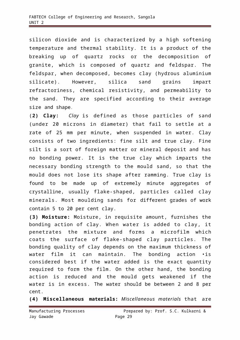
4. Permeability test: Permeability is measured by the quantity of air that will pass through a standard specimen of the sand under a given pressure in a prescribed time. The permeability apparatus uses the standard rammed 5.08 cm diameter by 5.08 cm height test piece.
A permeability meter, as shown in Fig. has a cylindrical water tank in which an inverted bell or air holder, properly balanced, is floating. By properly opening the three-way valve, air which is trapped under the bell will flow through the sand specimen as shown. Mercury around the bottom of the specimen tube provides an air tight seal. The pressure of this air is obtained with the water manometer and the straight scale. It should be close to 10 cm of water which correspond to a pressure of 10 gm per cm2.
Figure: Permeability meterPermeability number is defined as the volume of air in cc that will pass per
minute under a pressure of 1 gm per cm 2 through a specimen which is 1 cm2 in cross-sectional area and 1 cm deep. The permeability number is calculated using the following formula
Permeability number = v *h P * a * I
Where v = volume of air …………………………. = 2,000 cc. k = height of the sand specimen………… = 5.08 cm. p = air pressure …………………………… =1 0 gm/ cm2 a = cross-sectional area of the speimen = 20.268 cm2. t =time for 2,000 cc of air in seconds
Since v, h, p, and a are constants, this formula reduces to,
Permeability = 3, 007.2
time.in.sec5. Compression-strength test:
This test has been performed to test the holding power of various bonding materials in green and dry sand. Compression tests are the most common tests. Also tension, shear and transverse tests are sometimes used.
Manufacturing Processes Prepared by: Prof. S.C. Kulkarni & Jay Gawade Page 38

FABTECH College of Engineering and Research, Sangola UNIT 2
The green compressive strength (kgf/cm2) of foundry sand is maximum compressive strength a mixture is capable of developing when moist. The rammed sand specimen 5.08 cm high x 5.08 cm diameter is pushed out of the specimen tube and placed with the end that was uppermost in ramming against the upper plate of a universal sand strength machine. The machine is so constructed that it register a continuously increasing load until rupture of the specimen takes place. The load is applied at a rate of about 2 kgf/ cm2 until the specimen breaks. The compression value is read directly on the green compression scale of the testing machine.6. Mould and core hardness test: This test is performed by a mould- hardness tester in the foundry to determine how hard a mould has been rammed. The tester is about the size of a pocket watch and the hardness test can be made within a few seconds. It operates on the same principle as a Brinell hardness into the surface of the mould and the depth of penetration is indicated on the dial of the tester in hundredths of a millimeter. The hardness can also be read on another scale in kgf/ cm2.
CORE MAKING:-CO2 Core Making / mould making:The sand mixture including pure silica sand (without clay) and sodium silicate liquid base binder (water glass) are mixed in a muller for about 3 to 4 min. The moisture content should not exceed 3%. Sawdust (about 1.5%) and asbestos powder (upto 5%) make the cores deformable and collapsible. The prepared mixture is packed in the core box for core making manually or by machines. After this, CO2 reacts with sodium silicate to form silica gel which binds the sand grains together to provide strength and hardness to the core. The chemical reaction is as follows:-
Na2SiO3 + CO2 Na2CO3 + SiO2
(Sodium Silicate) (Silica gel)
The gassing process last for about 15 to 30 sec.only. Immediately after gassing, the core is ready for use. This method is used in the piece and batch production of steel and iron castings. To improve the strength of these cores, they are dried at 200-5000 C.
Fig: CO2 core making Fig: CO2 mould makingShell Core Making:-Shell cores can be manually. Shell cores can also be produced on machines. The procedure of core making is as follows:- The core box is heated to a temperature of the order of 400 to 6000 F.
Manufacturing Processes Prepared by: Prof. S.C. Kulkarni & Jay Gawade Page 39

FABTECH College of Engineering and Research, Sangola UNIT 2
Sand mixed with about 2 to 5% thermosetting resin of phenolic type is either dumped or blown into the preheated metal core box. Where sand blowing is employed, it is preferred to use resin precoated sands to avoid resin segregation. The resin is allowed to melt to the specified thickness. The resin gets cued. The excess sand is dumped or removed. The hardened core is extracted no further baking.Cold box process of core making:-These sands do not call for heat treatment to get the required strength of the core. Catalysts are added to speed up the hardening of binders. The ready mix is poured into the core boxes where it is held for sufficient time until the required compressive strength is reached (300 to 500 Kpa). The core is then removed from the core box and allowed to stand in the air for 30 to 120 min. As a result, the core acquires strength of about 800 to 1200 Kpa.Cold curing sands have a lower strength than sands curable in hot boxes, and therefore they are largely used for the production of cores of moderately complex and simple configuration.The advantages of this method are:-Core boxes of wood, plastic and metal can be used, core production process can be mechanised, improves the quality of castings and increases the output. The method has found the widest application in the batch production of moderate sized and large-sized castings from iron and steel.
MECHANICAL TOOLS AND EQUIPMENT
Tools for foundry include different types of Moulding Machines and Sand Slingers, Core
making and Baking equipment, Power riddles, Mechanical conveyors, Sand mixers,
Material handling equipment and Sand aerators, etc.
MOULDING MACHINES
A 'Moulding Machine' may be defined as a device which, by means of a large number of
correlated parts and 'mechanisms, transmits and directs various forces and motions in
required directions so as to help the preparation of a sand mould.
Main functions of Moulding Machines: 1. Ramming of moulding sand.2. Rolling over or inverting the mould.3. Rapping the pattern.4. Withdrawing the pattern from the mould.
Every machine does not necessarily perform all the operations. Most machines perform a
combination of two or more of these. However, ramming of sand is the basic function of most
of these.
TYPES OF MOULDING MACHINES
Moulding processes may be classified as hand moulding or machine moulding
according to whether the mould is prepared by hand tools or with the aid of moulding
Manufacturing Processes Prepared by: Prof. S.C. Kulkarni & Jay Gawade Page 40

FABTECH College of Engineering and Research, Sangola UNIT 2
machines. Hand moulding is found to be economical when only a few castings are
required. Hand moulding is slow and it requires considerable skill to produce good
castings.
On the other hand, the use of moulding machine is advisable when large number of
repetitive castings is to be produced since hand moulding is more t ime consuming,
laborious and becomes expensive. The dimensions of machine-cast castings are
more accurate, in other words, it is possible to produce castings to close tolerances.
As a consequence, the weight of castings is reduced and material saved. The
working time per mould is similar than that required for hand moulding, this
means that, related to the same shop area, the output of castings is increased per unit
of time. In fine, machine moulding offers higher production rates and better quality
casting in addition to less heavy and lower costs, and no specialized knowledge or skill
is required on the part of the operator.
A moulding machine performs two important functions—it packs the sand and draws
the pattern. Moulding machines are, therefore, classified according to
(1) The method of compacting the moulding sand and
(2) The method of removing the pattern.
In any case, one or two patterns are fastened to a pattern plate which is installed in the
moulding machine. The patterns are made of metal, plastics or any other suitable material.
Classification of moulding machines according to the methods of compacting the sand:
1. Jar or Jolt or Jolting machine:
This machine consists of an air operated piston and cylinder. The air enters from the bottom
side of the cylinder and acts on the bottom face of the piston to raise it up. The top of the
piston is attached to the plate or table of the machine which carries the pattern and moulding
flask with sand filled in it. When the piston, and hence the table, has been raised to a
certain height the air below the piston is suddenly released, resulting in a sudden
dropping of table and the mould and an even packing of sand around the pattern in the
flask. The operation is repeated several times and quite rapidly. It is known as Jolting.
In the jolting method, the flask is first filled with the moulding sand and then the table supporting the flask is mechanically raised and dropped in succession. Due to the sudden change in inertia at the end of each fall, the sands get packed and rammed. The action of raising and sudden dropping the table is called "Jolting".Figure illustrates the principle of a jolt moulding machine in which the table 1, with the
plate and flask 3, filled with moulding sand, is raised to 30 to 80 mm at short intervals
by the plunger 8 when compressed air is admitted through the hose 9 and the channel
10. The air is next released through the opening 11 and the table drops down suddenly
and strikes the guiding cylinder 12 at its bottom. This sudden action causes the sand to
pack evenly around the pattern. Springs 13 are used to cushion the table blows and thus
Manufacturing Processes Prepared by: Prof. S.C. Kulkarni & Jay Gawade Page 41

FABTECH College of Engineering and Research, Sangola UNIT 2
reduce noise and prevent destruction of the mechanism and the foundation.
Figure: Jolting Machine
The drawback in this method is that sand is rammed hardest at the parting plane and
around the pattern and remains less dense in the top. This necessitates hand ramming
of the mould at the back after the jolting action is completed. These machines are
preferred for horizontal surfaces.
2. Squeezer Machine:
These machines may be hand operated or power operated. The pattern is placed over the
machine table, followed by the moulding flask.
In hand-operated machines the machine plate is lifted by a hand-operated mechanism
whereas in power machines it is lifted by the action of air pressure on a piston in the
cylinder in the same way as in jolt machine. The difference is that the table is not dropped
from height but is raised gradually. On the top of the machine column is provided an
overhead plate and the sand in the flask is squeezed between this plate and the upward
rising table. This enables a uniform pressing of sand in the flask.
A specific advantage of power operated machines over hand operated ones is that more
pressure can be applied in the former, which facilitates handling of a wider range of jobs.
In the squeeze method, moulding sand in the flask is squeezed between the machine table
and the overhead squeeze board pneumatically or hydraulically until the mould attains
the desired density.
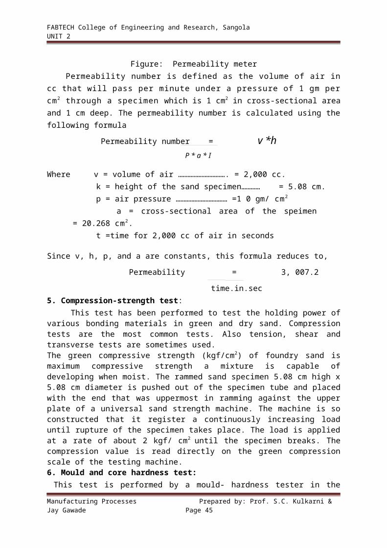
The principle of operation of a top squeezer machine is illustrated in Fig. The pattern 2 is
placed on a mould board which is clamped on the table 1. The flask 3 is then placed on the
mould board and the sand frame 4 on the flask. The flask and frame are filled with moulding
sand and leveled off. Next the table is raised by the table lift mechanism against the platen 5
on the stationary squeezer head 6. The plate enters the sand frame upto the dotted line and
compacts the moulding sand. After the squeeze, the table returns to its initial position.
Figure: Top squeezer Machine
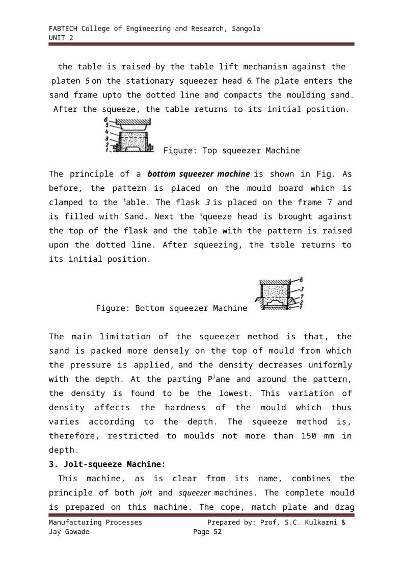
The principle of a bottom squeezer machine is shown in Fig. As before, the pattern is placed
on the mould board which is clamped to the table. The flask 3 is placed on the frame 7 and is
filled with Sand. Next the squeeze head is brought against the top of the flask and the table
Manufacturing Processes Prepared by: Prof. S.C. Kulkarni & Jay Gawade Page 42

FABTECH College of Engineering and Research, Sangola UNIT 2
with the pattern is raised upon the dotted line. After squeezing, the table returns to its initial
position.
Figure: Bottom squeezer Machine
The main limitation of the squeezer method is that, the sand is packed more densely
on the top of mould from which the pressure is applied, and the density decreases
uniformly with the depth. At the parting Plane and around the pattern, the density is found to
be the lowest. This variation of density affects the hardness of the mould which thus
varies according to the depth. The squeeze method is, therefore, restricted to moulds
not more than 150 mm in depth.
3. Jolt-squeeze Machine:
This machine, as is clear from its name, combines the principle of both jolt and squeezer
machines. The complete mould is prepared on this machine. The cope, match plate and drag
are assembled on the machine table in a reverse position, that is, the drag on the top and
the cope below. First the drag is filled with sand and then rammed by the jolting action of the
table. After leveling off the sand on the top, the assembly is turned upside down and placed
over a bottom board placed on the table. Then the cope is filled up with sand and the latter
rammed by squeezing between the overhead plate and the machine table. The overhead plate
is then swung aside and sand on the top leveled off, cope removed and the drag vibrated by
Air Vibrator. This is followed by removal of match plate and closing of two halves of the
mould for pouring. For giving two separate actions to the machine table, the machine
incorporates two separate cylinders and pistons at its bottom whose timings are well
synchronized to give the desired effects of jolting and squeezing one after the other.
4. Sand Slinger or Slinging Machine:
These machines are used for filling and uniform ramming of sand in moulds and are particularly adopted with advantage for large moulds. They can also be used in conjunction with other moulding devices, like Roll over machines and Pattern draw machines, so as to eliminate more manual operations.These machines are manufactured in both stationary and portable types. The former are used in large production foundries. The Portable type machines are mounted on wheels and travel in the shop on a fixed track. Eventually a Sand Slinger consists of a heavy base, a bin or hopper to carry sand, a bucket elevator to which are attached a number of buckets and a swinging arm which carries a belt conveyor and the sand impeller head. Properly conditioned sand is filled in the bin through the bottom of which it is fed to the elevator buckets. These buckets discharge the sand to the belt conveyor which conveys the same to the impeller head.This head can be positioned anywhere on the mould by swinging the arm. The head revolves
Manufacturing Processes Prepared by: Prof. S.C. Kulkarni & Jay Gawade Page 43

FABTECH College of Engineering and Research, Sangola UNIT 2
at a very high speed and, in doing so, throws a steam of sand into the flask at a great velocity. This is called Slinging. The force of sand ejection and striking into the flask is so great that the sand gets packed in the flask quite uniformly. This completes the satisfactory ramming automatically. Some machines require the operator to direct the sand stream into the flask by means of a hydraulically operated impeller head. This is obviously a very useful machine in large foundries. In the slinging operation, the consolidation and ramming are obtained by the impact of sand which falls at a very high velocity.
The principle of a sand slinger is illustrated in Fig.
Figure: Sand slinger
The overhead impeller head consists of the housing 1 in which the blade 2 rotates at a very high speed. The sand is delivered to the impeller through the opening 3 by means of conveyor buckets. The impeller head by the rotation of the blade throws the sand through the outlet 4 down into the flask over the pattern at a rate ranging from 500 to 2,000 kg per min. The density of the sand can be controlled by the speed of the blade. Mould produced by this method has adequate strength, since hardness is a function of sand velocity, which is controllable in a sand slinger. These machines are most often used for ramming medium-size to large moulds. A sand slinger does fast ramming, uniform ramming but involves high initial cost
Classification of moulding machines according to the method of removing the pattern from the mould:1. Straight-draw moulding machine: In the straight-draw moulding machine, the pattern 1 is fixed on the pattern plate 3 on the table-5, and the flask or moulding box 2 is placed over it and filled with sand. It is then roughly rammed round the edges of the box. The squeeze head is next swung over in position and it squeezes the mould. The flask is then lifted from the pattern by stripping pins 6.
Fig: Straight draw Moulding machine
2. Stripping-plate moulding machine:The principle of a stripping- plate moulding machine is illustrated in Fig. The stripping plate 4 is arranged between the flask 2 and pattern plate 3. The stripping plate has a recess whose
Manufacturing Processes Prepared by: Prof. S.C. Kulkarni & Jay Gawade Page 44
FABTECH College of Engineering and Research, Sangola UNIT 2
contours equal those of the pattern 1. When the mould is ready the pattern is withdrawn from the mould downwards through the stripping plate, which supports the mould when the pattern is removed.
Fig: Stripping plate moulding machine3. Turn-over moulding machine.
This is used for large size, high moulds, having parts which might easily break away.
In Fig., the flask 2 rests on the pattern plate 3 during the moulding operation. Then the flask
together with the work table 5 is rotated 1800 and pin 6 lift the table 5 together with the
pattern 1 out of the mould
Fig: Turn-over moulding machine
GREEN SAND MOULDING:-Green sand mould:-The sand mould prepared from natural molding sand in its green state is called green sand mold. The green sand mixture is prepared by mixing thoroughly silica sand (80%), clay (10 to 15%) and water (4 to 6 %). This mixture should be properly tempered before it is used. The green sand mold may be used for small and medium castings of ferrous and non-ferrous alloys. Since the green sand molds contain moisture, therefore certain defects like blow holes may occur in casting. The surface finish of castings made in green sand molds is also not good. Green sand moulding can be done manually or by using machines.
TERMS RELATED TO Green SAND MOULDS
Various terms related to sand moulds are illustrated in Fig. Cope is the upper part and Drag the lower part of the moulding flask. Runner is the passage through which molten metal is poured. Gate is the small passage connecting the runner to the mould cavity. Parting line is the line along which the sand surfaces of the drag and cope meet each other. Riser is the passage through which the molten metal rises up after filling the mould cavity. On seeing the metal through it, it is ensured that the mould has been completely filled. It also helps the escape of gases out of the mould. Pouring Basin is the enlarged portion, in the form of a countersunk, at the top of the runner
Manufacturing Processes Prepared by: Prof. S.C. Kulkarni & Jay Gawade Page 45

FABTECH College of Engineering and Research, Sangola UNIT 2
Fig: Sectional view of a Green sand mould
MOULDING PROCEDUREThe procedure for making a mould in either green or dry sand is as follows:
1. First of all a suitable flask is selected, large enough to accommodate the
pattern and also allow some space around it for ramming of sand.
2. The drag part is placed upside down on the moulding board.
3. The pattern is placed on the board inside the flask in such a position that space is
left for gate cutting.
4. If in two parts, the lower part of the pattern is placed in the (lag.
5. If facing sand is used, it is placed all along the pattern surface to a suitable depth (say
25 mm.
6. The drag is then filled with ordinary moulding sand and rammed properly.
7. The excess sand is cut-off to bring it in level with the edges of the flask.
8. A small amount of dry loose sand is sprinkled over the top surface and the drag turned
upside down, along with a bottom board placed over it, after venting.
9. The cope is then placed over the drag and the top part of the pattern (if it is in two
parts) assembled in position.
10. Dry, loose, parting sand is then sprinkled over the entire surface of the drag and
pattern.
11. Runner and riser are put in positions and supported vertically by tucking a small
amount of moulding sand around them.
12.The facing sand, if used, is again put around the pattern surface to the usual depth.
13. Gaggers, if used, are then placed in position and the cope filled with ordinary moulding
sand and rammed.
14. Excess sand is then cut-off, runner and riser pins removed, venting performed,
Manufacturing Processes Prepared by: Prof. S.C. Kulkarni & Jay Gawade Page 46

FABTECH College of Engineering and Research, Sangola UNIT 2
pouring basin formed and dry sand sprinkled on the top surface.
15. A bottom board is placed over the cope and the latter rolled over.
16. The pattern parts are then removed from both the drag and cope.
17. Repairs, if any, are made and gates cut,
18. Dressing is then applied.
19. If it is a dry sand mould, it is baked.
20. The dry sand cores, if any, are located in position and mould closed for pouring.
An example of making a simple green sand mould is shown in following figure:
Fig: Making a simple Green sand mould
Shell Moulding ProcessThe shell moulding process (also called croning process) consists of making a
mould that has two or more thin, shell like parts consisting of thermosetting resin-bonded sand. The resins include phenol-formaldehydes, urea formaldehydes and poly esters. It is mixed with sand as a powder from 3 to 10 percent by weight. It may be applied as a liquid and then dried on the sand grains. The mixture for moulding must be dry and free flowing. The procedure for shell moulding is as follows:
1. A metal pattern, heated to about 175°C to 350°C, is clamped over a box containing sand mixed with thermosetting resin, as shown in Fig. (a)
2. The box and pattern are inverted for a short time, as shown in Fig. (b). The mixture when comes in contact with hot pattern, it causes an initial set and builds up a coherent sand shell next to the pattern. This takes 5 to 20 seconds only. The thickness of this shell is about 6 mm to 18 mm and is dependent on the pattern temperature, dwell time on the pattern and the sand mixture.
3. The box and pattern are brought in its original position, as shown in Fig. (c). The shell of resin bonded sand is retained on the pattern surface, while the unaffected sand falls into box. The shell, still on the pattern is cured by heating it in an oven from 250°C to 350°C for 1 to 3 minutes. The time depends upon the type of resin and shell thickness.
4. The assembly is removed from the oven and the shell is stripped from the pattern by ejector pins as shown in Fig. (d). In order to obtain clean stripping, a silicon parting agent may be sprayed on the pattern.
Manufacturing Processes Prepared by: Prof. S.C. Kulkarni & Jay Gawade Page 47

FABTECH College of Engineering and Research, Sangola UNIT 2
Figure: Shell Moulding
Special Casting Techniques:
1. Investment Casting:It is also known as lost wax process or precision casting. The castings produced by this method are within very close tolerances and do not require subsequent machining. The procedure adopted for investment casting is as follows:
1. First of all, a metal die for casting the wax patterns is made.2. The wax patterns and gating systems are produced from the metal dies by injection.
The wax is injected into the mould at 50°C to 80°C and at a pressure of 3.5 to 7MPa.3 The wax assembly is dipped into slurry of a refractory coating material. A typical slurry consists of silica flour suspended in ethyl silicate solution of suitable viscosity to produce uniform casting after drying. After dipping, the assembly is coated by sprinkling it with silica sand and allowed to dry.4. The coated wax assembly is now invested in the mould. This is done by inverting the wax assembly on a table, surrounding it with a paper-lined steel flask and pouring the investment moulding mixture consisting of either sand 95%, water 27 to 31% and 5% alumina cement or sand with 3% or more ethyl silicate or sodium silicate around the pattern. The moul6 material settles by gravity and completely surrounds the pattern as the work table is vibrated. The moulds are then allowed to dry in air for 2 to 3 hours.
5. The wax is melted out of the hardened mould by heating it in an inverted position at 90°C to 150°C. The melted wax may be collected and re-used.6. The mould is again heated at the rate of 40°C to 70°C per hour from about 150°C to 1000°C for ferrous alloys and 650°C for aluminium alloys. The temperature is controlled so that the mould is at a temperature desirable for pouring the particular alloy. The investment moulds may be poured under simple gravitational force or under the force of applied air pressure or by centrifugal force.
Manufacturing Processes Prepared by: Prof. S.C. Kulkarni & Jay Gawade Page 48

FABTECH College of Engineering and Research, Sangola UNIT 2
Figure: Investment casting
Following are the advantages and disadvantages of investment casting:Advantages1. The close tolerances (1 0.05 mm) are easily maintained in average work.2. It produces extremely smooth surfaces. 3. It eliminates most machining operations including thread cutting and gear tooth forming.4. It is adaptable to all metallic alloys.
Disadvantages1. The investment moulds as well as the materials from which they are made are single
purpose, therefore they cannot be reused. This increases cost of production.
2. The larger objects are impractical for investment casting due to equipment size limits.
2. Centrifugal Casting:A casting process, in which molten metal is poured and allowed to solidify while the
mould is revolving, is called centrifugal process. The castings produced under this centrifugal force are called centrifugal castings. The centrifugal casting may be classified into the following three types:
a) True centrifugal castingb) Semi-centrifugal castingc) Centrifuginga) True centrifugal casting:
This process is especially employed for casting articles of symmetrical shape e.g.,
Manufacturing Processes Prepared by: Prof. S.C. Kulkarni & Jay Gawade Page 49

FABTECH College of Engineering and Research, Sangola UNIT 2
cast iron pipes, sleeves, steel gun barrels and other castings of cylindrical form.
Figure: Centrifugal casting
In this process, as shown in Fig., the mould is made of metal and lined with refractory material or sand. The molten metal is poured by ladle into the cavity of rapidly rotating mould. The centrifugal force directs the fluid metal to the inner surface of the mould with considerable pressure where solidification occurs forming hollow castings. The outside of mould is covered by water bath for quick cooling of metal.
The main advantages of a true centrifugal casting process are(a) It is a quick and economical than other methods.(b) It eliminates the use of risers, feed heads, cores etc.(c) The ferrous and non-ferrous metals can be casted by this process.
(d) The castings produced by this process have dense and fined grained structure with all impurities forced back to the centre where they can be frequently machined out.
b) Semi-centrifugal casting: This process is employed for making large size castings which are symmetrical about their own axis such as pulleys, spoked or disc wheels, gears, propellers etc. In this process, as shown in Fig. a , the mould is rotated about its vertical axis in a properly balanced state and the metal is poured into a central sprue from where it enters the hub. From the hub, it is forced outward to the rim by the centrifugal force. It may be noted that several moulds can be cast at one time. If a central hole is required in the casting, a dry sand central core may be used in the centre. The speed of rotation of these moulds is lower than that of true centrifugal casting. This is due to the reason that the moulds are of larger size and there is a tendency of the molten metal to flow out of the mould joint. Because of the lower speed, the pouring pressure produced is low and thus the impurities are not effectively separated from the metal.
c) Centrifuging:
Manufacturing Processes Prepared by: Prof. S.C. Kulkarni & Jay Gawade Page 50

FABTECH College of Engineering and Research, Sangola UNIT 2
The castings of irregular shape can be produced by this method. Also a large number of small size castings can be produced at one time.
In this process, as shown in Fig. number of small mould cavities is made symmetrically around a common central sprue and the metal is fed to them by radial gates. In this case, the mould cavities are not rotated about their own axis, but they are rotated about the central sprue which acts as the axis of rotation. Since the centrifugal force used to fill the mould cavities is not same for all the castings, therefore it is not a purely centrifugal process.
Fig. b: Centrifuging Fig. a: Semi centrifugal casting
3. Continuous Casting:
This process is generally employed for the production of rods, squares, pipes, tubes, sheets etc.
It consists of pouring the molten metal into the upper end of a long vertical metal mould (open at both ends) and cooling rapidly by water. The solidified product is withdrawn by gravity in a continuous length from the lower end of the mould. The following two processes are commonly used for continuous casting of various metals and alloys.
a) Asarco process:
It is one of the most popularly used process. In this process, as shown in Fig. (a), the molten metal is fed through gravity pull, into the mould lined with graphite.
The molten metal is solidified by the circulating water in the jacket around the open mould. The pulling rolls are provided below the mould to withdraw the solidified metal from the mould at a uniform speed. A saw is provided below the rolls to cut the product to desired length. This process is widely used for copper and bronzes.
Manufacturing Processes Prepared by: Prof. S.C. Kulkarni & Jay Gawade Page 51
FABTECH College of Engineering and Research, Sangola UNIT 2
b) Reciprocating process: In this process, as shown in Fig. (b), the copper mould reciprocates up and down with the
surrounding water jacket. The molten metal is poured into the mould at a uniform speed, through a pipe connected to the furnace. A valve controls the flow of molten metal. The solidified portion of the casting is withdrawn by the rolls at a constant speed. The movement of the rolls and the reciprocating motion of the rolls are properly controlled by means of cams.
Fig: Continuous casting process
4. Gravity & Pressure Die Casting:The die casting or pressure die casting may be defined as the casting which uses the permanent mould (die) through which the molten metal is introduced by means of pressure. The castings produced by die casting method require very little machining. The dies are usually made in two parts which must be locked securely before molten metal is forced into them under high pressures of 7 to 700 MPa. The pressure may be obtained by the application of compressed air or by hydraulically operated pistons. The ferrous alloys are not yet commercially die-casted because of their high pouring temperature. Following are the two types of die casting machines commonly used for die casting:a) Hot chamber die casting machine b) Cold chamber die casting machine
a) Hot chamber die casting machine:
The hot chamber die casting machine of the submerged type is shown in Fig. The molten metal is forced in the die cavity at pressures from 7 to 14 MPa. The pressure may be obtained by the application of compressed air, as shown in Fig. (a) Or by a hydraulically operated plunger, as shown in Fig. (b).
Manufacturing Processes Prepared by: Prof. S.C. Kulkarni & Jay Gawade Page 52

FABTECH College of Engineering and Research, Sangola UNIT 2
Fig: Hot chamber die casting machineIn the first method, the goose neck is lowered into the molten metal for filling it. It is then raised and connected to the die neck. A suitable mechanism is provided to raise and lower the goose neck. The compressed air at a pressure of about 2.5 to 5 MPa is now injected into the goose neck to force the molten metal into the die.In the second method, the plunger acts inside a cylinder formed at the end of the goose neck, which is immersed in a pot of molten metal. A port is provided near the top of the cylinder to allow the entry of the molten metal. The downward stroke of the plunger pushes the molten metal through the goose neck into the die.
The hot chamber die casting machine is used for casting zinc, tin, lead and other low melting alloys.b) Cold chamber die casting machine: In cold chamber die casting machine, the melting unit is usually separate and molten metal is transferred to injection mechanism by ladle. The pressure on the casting metal in cold chamber die casting machine may vary from 21 to 210 MPa and in some cases may reach 700 MPa. The greater pressures are required for semi- molten alloys to compensate for reduced fluidity resulting from low pouring temperatures. This process is used for casting aluminium, magnesium, copper base alloys and other high melting alloys. The cold chamber die-casting machine, as shown in Fig. (a) consist of a pressure chamber of cylindrical shape fitted with a piston or ram that is usually operated by hydraulic pressure. A measured quantity of molten metal is brought in a ladle from the melting pot to a chamber and forced into the closed die sections by applying hydraulic pressure upon the piston. The cycle is completed in the following four steps:
1. The metal is loaded in the chamber. Fig.(a)2. The plunger forces the metal into the die cavity, as shown in Fig. (b).3. After the metal solidifies, the die is opened, as shown in Fig. (c).4. The casting, together with the slag of the excess metal, is ejected from the die, as
shown in Fig. (d).
Manufacturing Processes Prepared by: Prof. S.C. Kulkarni & Jay Gawade Page 53

FABTECH College of Engineering and Research, Sangola UNIT 2
Fig: Cold chamber die casting machine
Following are the advantages and disadvantages of die castingAdvantages:
1. The rapid and economical production of large quantities of identical parts can be achieved.
2. The parts having smooth surfaces and close dimensional tolerances may be produced, very little machining is required.
3. The parts having thin and complex shapes can be casted accurately and easily.4. The die casting requires less floor area than is required by other casting processes.5. The castings produced by die-casting process are less defective with increased
casting soundness.
6. The rapid cooling rate produces high strength and quality in many alloys.7. The inserts, if required, can be casted easily in desired places.
8. The die retains its trueness and life for longer periods. For example, the life of a die for zinc base castings is upto one million castings, for copper base alloys upto 75,000 castings and for aluminium base alloys upto 50,000 castings.
Disadvantages: 1. The cost of equipment and die is high.2. There is a limited range of non-ferrous alloys which can be used for die castings.3. The die castings are limited in size.4. It requires special skill in maintenance.
Manufacturing Processes Prepared by: Prof. S.C. Kulkarni & Jay Gawade Page 54

FABTECH College of Engineering and Research, Sangola UNIT 2
GRAIN SHAPE AND SIZE OF SANDThe shape and size of sand grains has a great effect on the processing properties of moulding and core sands. The shape of the grains and number of similar grains in the sand determine the possibility of its application in various types of foundry practice.Shapes of sand grains vary from angular to sub-angular to rounded and compound. Use of angular grains-(obtained during crushing of rocks or hard sand stones) is avoided as these grains have a large surface area. Thus a higher percentage of binders are required to bring in the desired strength. Rounded shape grain sands are best as moulding sand. The grains contribute to higher bond strength in comparison to angular grains. However, rounded grain sand has higher thermal expandability than angular grain sand. Sub-angular grains can be taken as a better compromise as its characteristics lie in between angular and rounded shape grains. Fig. below shows the shapes of the sands.
Angular Sub-angular Round Figure: Shape of sands grains
Compound grains are cemented together such that they fail to separate when screened. They may consist of round, sub angular or angular grains or a combination of the three. Compound grains are least desirable in sand mixtures as they have a tendency to disintegrate at high temperatures. In actual practice, however, sharp, irregular shaped grains are usually preferred because of their ability to interlock and add strength to the mould.
There are again three distinct sizes of sand grains:
1. Fine 2.Medium 3.Coarse.
For small and intricate castings the use of fine sand is desirable, so that all the details of the mould will be brought out sharply.
Medium sand is used in bench work and light floor work such as making machinery castings having from 1 to 50 mm sections. As the size of the casting increases, the sand particles likewise would be coarser to permit the ready escape of gases that are generated in the mould.
Grain size is determined by passing the sand through screens or sieves with certain opening sizes which are measured in microns. The preferred size of sand for casting is preferably kept in the range of 0.3-0.15 mm. Presently in foundries; preference is given to the finer sands. The finer grain sizes have higher resistance to metal penetration and erosion. However this type is having a higher thermal expansion defects.
Manufacturing Processes Prepared by: Prof. S.C. Kulkarni & Jay Gawade Page 55

FABTECH College of Engineering and Research, Sangola UNIT 2
SAND PREPARATION
Preparation of sand includes:
(1) Mixing of sand (2) Tempering of sand (3) Sand conditioning.
1. Mixing of sand:
Foundries use a great deal of moulding and core sands. From 4 to 5 m 3 of moulding sand is expended to make one tonne of sound casting. But very few natural sands have all the qualities that moulding sand should possess. So it is usual to make up the deficiency of sand in any particular characteristic by mixing it with other sands or other substances which possess that characteristic in a high degree. Generally, it is mixed with clay, lime, magnesia, potash, soda, horse manure, sawdust, cow dung, coal dust, etc., in small quantities. Silica is a high fusing material. So sand is capable of withstanding high temperature but it has no bond. Hence, clay is a necessary bond to the moulding sand. But too much clay in sand will crack the mould after drying. The addition of other elements like lime, magnesia, iron oxide, soda, etc. reduces the melting point of silica. Hence smaller amount of these elements are added to make the casting soft. Coal dust is perhaps the most widely used substance, which accounts for the fact that most moulding sand is black in colour. The addition of coal dust tends to make the sand more open and helps to cool the mould after it has been poured. As soon as the molten metal comes in contact with the sand containing coal it dries the face of the mould and begins to heat the sand. The coal dust immediately gives off carbon dioxide gas, and water (moisture content) in the sand starts getting converted into steam. The coal dust thus absorbs a fairly high amount of heat and cools the sand, thereby preventing the grains from becoming overheated and fusing. A protective film of carbon monoxide or CO2 gases obtained from the coal also helps to keep the metal and sand separated from each other.
Mixing of moulding materials should ensure uniform distribution of clay, moisture and other constituents between the sand grains. The more uniform this distribution, the better the main qualities of the sand.
2. Sand tempering: To prepare foundry sand for making a mould, it must be tempered and cut through. The process by which sufficient moisture is added to the moulding sand is known as sand tempering. To temper the sand, water is thrown over the heap in a sheet by giving a backward swing to the pail as the water leaves it. Then the pile of sand is cut through, a shovelful at a time, letting the air through the clay in the sand and breaking up the lumps. This moistens the clay in the sand, making it adhesive. The pile is thus put in the best condition for working.
Manufacturing Processes Prepared by: Prof. S.C. Kulkarni & Jay Gawade Page 56

FABTECH College of Engineering and Research, Sangola UNIT 2
3. Sand conditioning: New sand as well as used sand must be properly conditioned before being used. Proper sand conditioning accomplishes uniform distribution of the binder around the sand grains, controls the moisture content, eliminates foreign particles, and aerates the sand so that it flows readily around and takes up the detail of the pattern. In general, sand conditioning consists of preparing the moulding sand to render it suitable for ramming in flasks.For limited production such as job-shop production of casting, the handling and conditioning of the moulding sand is done by hand. In a mechanised foundry, appropriate equipment and appliances are provided for this purpose. A popular machine for sand mixing is a ‘muller’ which kneades, shears, slices through, and stirs the sand in a heavy pot by means of several revolving rollers and knives. Before mixing all moulding materials are screened to remove large lumps of clay, pebbles, metal particles, and other foreign matter which may lead to casting spoilage. Shaker, rotary and vibratory screen what is called ‘ riddles’, are used for screening the sand. Metal particles are removed by ‘magnetic separators’. The moulding sand obtained in the sand muller requires aeration to separate the sand grains by ‘aerators’. This operation, sometimes called ‘fluffing’, is performed by aerators of various design.
Proper sand conditioning and preparation has the following advantages
1. The binder is uniformly distributed around the sand grains
2. The moisture is evenly dispersed in the sand mixture and the moisture content
properly controlled;
3. The sand gets aerated, causing the sand grains to separate and increasing the
flowability of sand
4. The sand is delivered at the proper temperature
5. The foreign particles are separated and removed from the sand mass.
Manufacturing Processes Prepared by: Prof. S.C. Kulkarni & Jay Gawade Page 57
Related Documents


![Complete Unit 2 Notes [2]](https://static.cupdf.com/doc/110x72/55cf9be0550346d033a7b5a3/complete-unit-2-notes-2.jpg)