Unit 1: Solar energy and Photovoltaic Time: 1 hour Method: Presentation 1.1 Solar Energy Solar energy is energy from the Sun in the form of radiated heat and light. It drives the climate and weather and supports life on Earth. Solar energy technologies make controlled use of this energy resource. Solar power is a synonym of solar energy or refers speci cally fi to the conversion of sunlight into electricity by photovoltaic cells, concentrating solar thermal devices or various experimental technologies. 1.1.1 Energy from the Sun About half the incoming solar energy is absorbed by water and land; the rest is reradiated back into space. Earth continuously receives 340 Wm -2 of incoming solar radiation (insolation) at the upper atmosphere. Approximately 30% is re ected fl back to space while the rest is absorbed by the atmosphere, oceans and land masses. After passing through the atmosphere, the insolation spectrum is split between the visible and infrared ranges with a small part in the ultraviolet. The absorption of solar energy by atmospheric convection (sensible heat transport) and evaporation and condensation of water vapor (latent heat transport) powers the water cycle and drives the winds. Sunlight absorbed by the oceans and land masses keeps the surface at an average temperature of 14 °C. The conversion of solar energy into chemical energy via photosynthesis produces

Welcome message from author
This document is posted to help you gain knowledge. Please leave a comment to let me know what you think about it! Share it to your friends and learn new things together.
Transcript
Unit 1: Solar energy and Photovoltaic
Time: 1hour
Method:Presentation
1.1 SolarEnergy
Solar energy is energy from the Sun in the form ofradiated heat and light. It drives the climate andweather and supports life on Earth. Solar energytechnologies make controlled use of this energy resource.
Solar power is a synonym of solar energy or refersspeci callyfi to the conversion of sunlight intoelectricity by photovoltaic cells, concentrating solarthermal devices or various experimental technologies.
1.1.1 Energy fromthe SunAbout half the incoming solar energy is absorbed by waterand land; the rest is reradiated back into space.
Earth continuously receives 340 Wm-2 of incoming solarradiation (insolation) at the upper atmosphere.Approximately 30% is re ectedfl back to space while the restis absorbed by the atmosphere, oceans and land masses.After passing through the atmosphere, the insolationspectrum is split between the visible and infrared rangeswith a small part in the ultraviolet.
The absorption of solar energy by atmospheric convection(sensible heat transport) and evaporation andcondensation of water vapor (latent heat transport)powers the water cycle and drives the winds. Sunlightabsorbed by the oceans and land masses keeps the surfaceat an average temperature of 14 °C. The conversion of solarenergy into chemical energy via photosynthesis produces
food, wood and the biomass from which fossil fuels arederived.
Solar radiation, along with secondary solar resourcessuch as wind and wave power, hydroelectricity andbiomass, account for over 99.9% of the available flow ofrenewable energy on Earth. The flows and stores of solarenergy in the environment are vast in comparison tohuman energy needs.
The total solar energy absorbed by Earth's atmosphere,oceans and land masses is approximately 3850 zettajoules (ZJ) per year.
Study materials in Renewable EnergyAreas for ITI students 5
Global wind energy at 80 m isestimated at 2.25 ZJ per year. Photosynthesis captures approximately 3ZJ per year in biomass. Worldwide electricity consumption wasapproximately 0.0567 ZJ in 2005. Worldwide energy consumption was0.487 ZJ in 2005.
# 1 zettajoule =1021 joules.
eused. A variety of electronicsystems may be prototyped by usingbreadboards, from small analog anddigital circuits to completecentral processing units (CPUs).
3.7.1 Typicalspeci cationsfiA modern solderless breadboardconsists of a perforatedtin plated phosphor bronze or nickel silver alloy springclips under the perforations. The spacing between theclips (lead pitch) is typically 0.1" (2.54 mm). Integratedcircuits (ICs) in dual in-line packages (DIPs) can beinserted to straddle the centerline of the block.Interconnecting wires and the leads of discretecomponents (such as capacitors, resistors, inductors, etc.)can be inserted into the remaining free holes tocomplete the circuit. Where ICs are not used, discretecomponents and connecting wires may use any of the holes.Typically the spring clips are rated for 1 Ampere at 5 Voltsand 0.333 Amperes at 15 Volts (5 Watts).
Study materials in Renewable EnergyAreas for ITI students 23
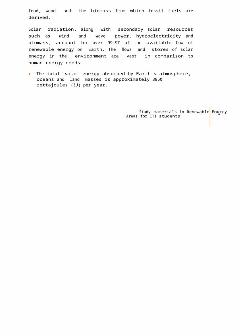
3.7.2 Bus andterminal stripsLogical 4-bits adder where sums arelinked to LEDs on a typicalbreadboard
Example breadboard drawing. Twobus strips and one terminalstrip in one block. 25consecutive terminals in a busstrip connected (indicated bygaps in the red and blue lines).Four binding posts depicted at thetop.
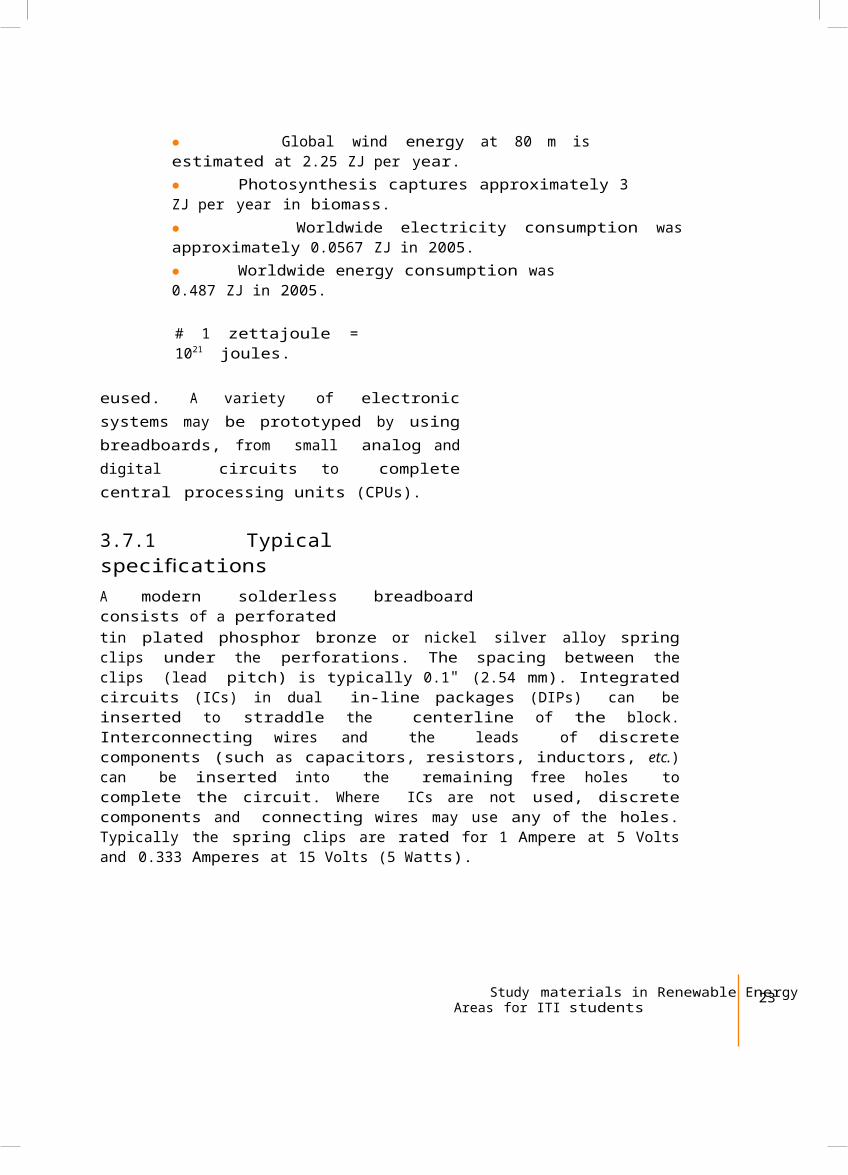
Close-up of a solderlessbreadboard. (An IC straddling thecenterline is probed with anoscilloscope.)
Solderless breadboards areavailable from several differentmanufacturers, but most ofthem share a similar layout. Thelayout of a typical solderlessbreadboard is made up from twotypes of areas, called strips.Strips consist of interconnectedelectrical terminals.
3.7.3 TerminalstripsThis is the main area, which is used to hold most ofthe electronic components.
In the middle of a terminal strip of a breadboard, onetypically ndsfi a notch running in parallel to the longside. The notch is to mark the centerline of the terminalstrip and provides limited airflow (cooling) to DIP ICsstraddling the centerline. The clips on the right andleft of the notch are each connected in a radial way;typically five clips (i.e., beneath five holes) in a row oneach side of the notch are electrically connected. The fiveclip columns on the left of the notch are often marked as A,B, C, D, and E, while the ones on the right are marked F, G,H, I and J. When a "skinny" Dual Inline Pin package (DIP)
integrated circuit (such as a typical DIP-14 or DIP-16,which have a 0.3 inch separation between the pin rows) isplugged into a breadboard, the pins of one side of thechip are supposed to go into column E while the pins ofthe other side go into column F on the other side of thenotch.
3.7.4 BusstripsThis is used to provide power to theelectronic components.
A bus strip usually contains two columns, one for ground,and one for a supply voltage. But some breadboards onlyprovide a single-column power distributions bus strip oneach long side. Typically the column intended for asupply voltage is marked in red, while the column forground is marked in blue or black. Some manufacturersconnect all terminals in a column. Others just connectgroups of e.g. 25 consecutive terminals
24 Trainers textbook for
Solar Lighting Systems
in a column. The latter design provides a circuit designerwith some more control over crosstalk (inductively couplednoise) on the power supply bus. Often the groups in a busstrip are indicated by gaps in the color marking.
Bus strips typically run down one or both sides of aterminal strip or between terminal strips. On largebreadboards additional bus strips can often be found onthe top and bottom of terminal strips.
Some manufacturers provide separate bus and terminalstrips. Others just provide breadboard blocks whichcontain both in one block. Often breadboard strips orblocks of one brand can be clipped together to make alarger breadboard.
In a more robust and slightly easier to handle variant,one or more breadboard strips are mounted on a sheet ofmetal. Typically, that backing sheet also holds a numberof binding posts. These posts provide a clean way toconnect an external power supply. Several images in thisarticle show such solderless breadboards.
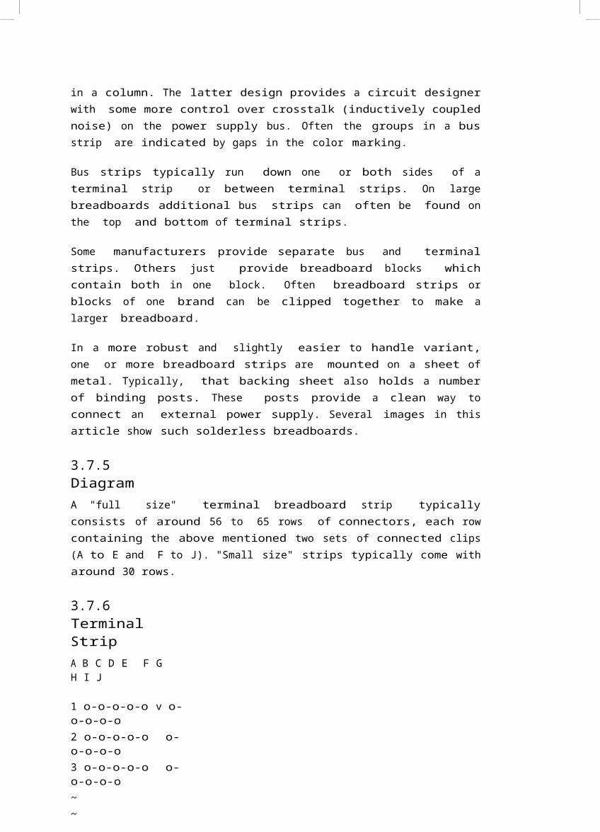
3.7.5DiagramA "full size" terminal breadboard strip typicallyconsists of around 56 to 65 rows of connectors, each rowcontaining the above mentioned two sets of connected clips(A to E and F to J). "Small size" strips typically come witharound 30 rows.
3.7.6TerminalStripA B C D E F GH I J
1 o-o-o-o-o v o-o-o-o-o2 o-o-o-o-o o-o-o-o-o3 o-o-o-o-o o-o-o-o-o~~
61 o-o-o-o-o o-o-o-o-o62 o-o-o-o-o o-o-o-o-o63 o-o-o-o-o ^o-o-o-o-o
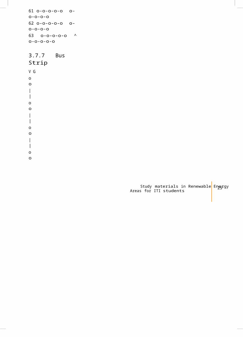
3.7.7 BusStripV Goo||oo||oo||oo
Study materials in Renewable EnergyAreas for ITI students 25
| |o o| || |o o| |o o| |o o| |o o| |o o| || |~~o o| |o o
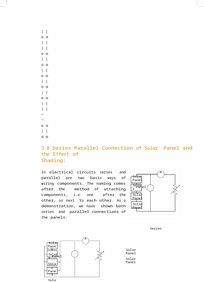
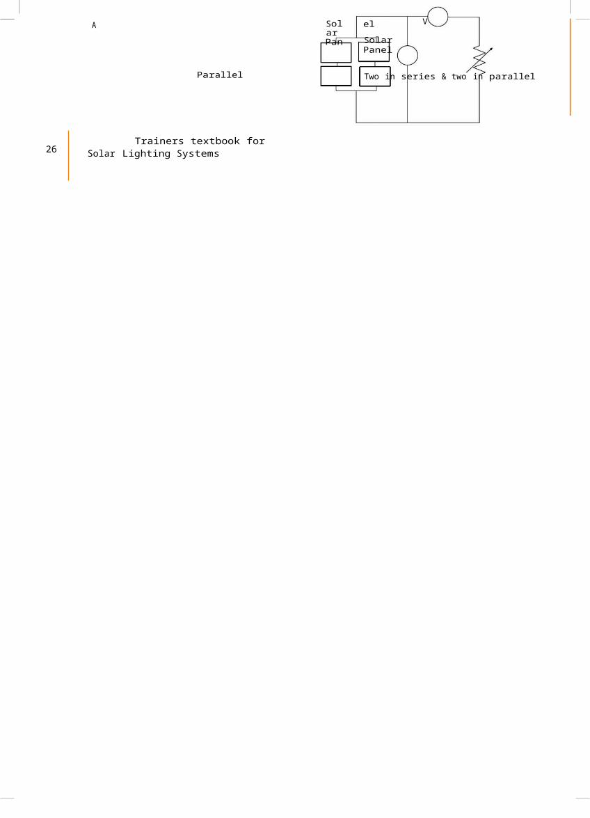
3.8 Series Parallel Connection of Solar Panel and the Effect ofShading:
In electrical circuits series andparallel are two basic ways ofwiring components. The naming comesafter the method of attachingcomponents, i.e. one after theother, or next to each other. As ademonstration, we have shown bothseries and parallel connections ofthe panels.
ASolarPanelSolar V Panel
SolarPanel
SolarPanel
Series
ASolarPanel
Solar V Panel
Solar
Panel
Sola
SolarPanelSolarPanel
A SolarPan
el V
SolarPanel
Parallel Two in series & two in parallel
26 Trainers textbook for
Solar Lighting Systems
Unit 4: PV Devices in India
Time: 3hours
Method: Demonstration,presentation
4.1Introduction
PV modules inIndia
PV modules are usually made from strings of crystallinesilicon solar cells. These cells are made of extremely thinsilicon wafers (about 300 µm) and hence are extremelyfragile. To protect the cells from damage, a string of cellsis hermetically sealed between a layer of toughened glassand layers of ethyl vinyl acetate (EVA). An insulatingtedlar sheet is placed beneath the EVA layers to givefurther protection to the cell string. An outer frame isattached to give strength to the module and to enableeasy mounting on structures. A terminal box is attachedto the back of a module; here, the two ends (positiveand negative) of the solar string are welded or soldered tothe terminals. This entire assembly constitutes a PVmodule. When the PV module is in use, the terminals areconnected either directly to a load, or to anothermodule to form an array. Single PV modules of capacitiesranging from 3 Wattpeak ( Wp) to 240 Wattpeak ( Wp) canprovide power for different loads. For large powerapplications, a PV array consisting of a number of modulesconnected in parallel and/or series is used.
4.1.1 Standard Capacity/Ratingsand Speci cationsfiThe wattage output of a PV module is rated in terms ofwattpeak ( Wp) units. The peak watt output power from amodule is de nedfi as the maximum power output that the
module could deliver under standard test conditions (STC).The STC conditions used in a laboratory are
1000 watts per square metresolar radiation intensity Air-mass 1.5 referencespectral distribution 25 °C ambienttemperature.
SPV modules of various capacities are available, and arebeing used for a variety of applications. Theoretically,a PV module of any capacity (voltage and current) ratingcan be fabricated. However, the standard capacitiesavailable in the country range from 3Wattpeak ( Wp) to 240 Wattpeak ( Wp). The voltage output ofa PV module depends on the number of solar cellsconnected in series inside the module. In India, acrystallinesilicon module generally contains 36 solar cells connectedin series. The module provides
Study materials in Renewable EnergyAreas for ITI students 27
a usable direct current (DC) voltage of about 16.5 V, whichis normally used to charge a12-Vbattery.
In an SPV system, the components other than the PV moduleare collectively known as‘balance of system’ (BoS), which includes batteries forstorage of electricity, electronic charge controller,inverter, etc. These batteries are charged during thedaytime using the DC power generated by the SPV module.The battery/battery bank supplies power to loads duringthe night or non-sunny hours. An inverter is required toconvert the DC power from the PV module or battery to ACpower for operating the load. Some loads such as DC pumpsdo not require an inverter or even a battery bank.
4.2 CompactFluorescent Lamps
Compact uofl rescent lamps (CFLs) combine the energyef ciency fi of uofl rescent lighting with the convenience andpopularity of incandescent xtufi res. CFLs can replaceincandescents that are roughly 3–4 times their wattage,saving up to 75% of the initial lighting energy. AlthoughCFLs cost 3–10 times more than comparable incandescentbulbs, they last 6–15 times as long (6,000–15,000 hours).See How CFLs Compare with Incandescents for moreinformation.
4.2.1 How They Work CFLs work much like standard uofl rescent lamps. They consist of two parts: a gas- llefi d
tube, and magnetic or electronic ballast. The gas in the tube glows with ultraviolet light whenelectricity from the ballast flows through it. This in turnexcites a white phosphor coating onthe inside of the tube, which emits visible lightthroughout the surface of the tube.
CFLs with magnetic ballasts icker fl slightly when theystart. They are also heavier than those with electronicballasts. This may make them too heavy for some lightxtufi res. Electronic ballasts are more expensive, but
light immediately (especially at low temperatures).They are also more ef cientfi than magnetic ballasts. Thetubes will last about 10,000 hours and the ballast about
50,000 hours. Most currently available CFLs haveelectronic ballasts.
CFLs are designed to operate within a speci cfi temperaturerange. Temperatures below the range cause reduced output.Most are for indoor use, but there are models available foroutdoor use. You can nd fi a CFL's temperature range onmost lamp packages. You should install outdoor CFLs inenclosed xtufi res to minimize the adverse effects of coldertemperatures.
CFLs are most cost effective and ef cientfi in areas wherelights are on for long periods of time. You'll experiencea slower payback in areas where lights are turned on forshort periods of time, such as in closets and pantries.Because CFLs do not need to be changed often, they are idealfor hard-to-reach areas.
28 Trainers textbook for
Solar Lighting Systems
4.2.2 Types of CompactFluorescent LampsCFLs are available in a variety of styles or shapes. Somehave two, four, or six tubes. Others have circular orspiral-shaped tubes. The size or total surface area of thetube(s) determines how much light it produces.
Some CFLs have the tubes and ballast permanentlyconnected. Other CFLs have separate tubes and ballasts.This allows you to change the tubes without changing theballast. There are also types enclosed in a glass globe.These look somewhat similar to conventional incandescentlight bulbs, except they're larger.
Sub-CFLs tfi most xtufi resdesigned for incandescentlamps. Although most CFLs tfiinto existing 3-way lightsockets, only a few special CFLmodels can be dimmed.
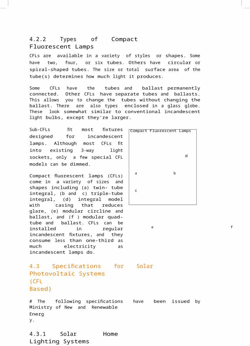
Compact uofl rescent lamps (CFLs)come in a variety of sizes andshapes including (a) twin- tubeintegral, (b and c) triple-tubeintegral, (d) integral modelwith casing that reducesglare, (e) modular circline andballast, and (f ) modular quad-tube and ballast. CFLs can beinstalled in regularincandescent xtufi res, and theyconsume less than one-third asmuch electricity asincandescent lamps do.
Compact Fluorescent Lamps
d
a b
c
e f
4.3 Speci cationsfi for SolarPhotovoltaic Systems(CFLBased)
# The following speci cations fi have been issued byMinistry of New and RenewableEnergy.
4.3.1 Solar HomeLighting Systems
I.De nitiofinA solar home lighting system aims at providing solarelectricity for operating lights and/or fan or energizinga DC operated portable TV set for speci edfi hours ofoperation per day.
II.ModelsMODEL – 1 (1 LightPoint)
ComponentSpeci cationsfi
PV Module 1X 18 W
under STC Lamps 1X
CFL (9W /11W )
Battery 1X 12V, 20 AH Tubular plate LeadAcid or VRLA Gel Type
Study materials in Renewable EnergyAreas for ITI students 29
Other components: control electronics, module mountinghardware, and battery box, inter-connecting wires /cables, switches, Operation, instruction andmaintenance manual.
MODEL - 2 (2 Lights)
ComponentSpeci cationsfi
PV Module 1X 37 W
under STC Lamps 2X
CFLs (9W /11W )
Battery 1X 12V, 40 AH Tubular plate LeadAcid or VRLA Gel Type
Other components: control electronics, module mountinghardware, and battery box, inter-connecting wires /cables, switches, Operation, instruction andmaintenance manual.
MODEL - 3 (2 lights and 1fan)
ComponentSpeci cationsfi
PV Module(s) 2X 37 W or 1 X 74 W
under STC Lamps 2X CFLs (9W /11W
)
Fan 1X DC Fan (with wattageless than 20 W )Battery 1X 12V, 75 AH Tubular Plate Lead Acidor VRLA GEL Type
Other components: control electronics, module mountinghardware, and battery box, inter-connecting wires /cables, switches, Operation, instruction andmaintenance manual.
MODEL - 4 (4lights)
ComponentSpeci cationsfi
PV Module(s) 2X 37 W or 1 X 74 W
under STC Lamps 4 X CFLs (9W
/11W )
Battery 1X 12V, 75 AH Tubular Plate Lead Acidor VRLA Gel Type
Other components: control electronics, module mountinghardware, and battery box, inter-connecting wires /cables, switches, Operation, instruction andmaintenance manual.
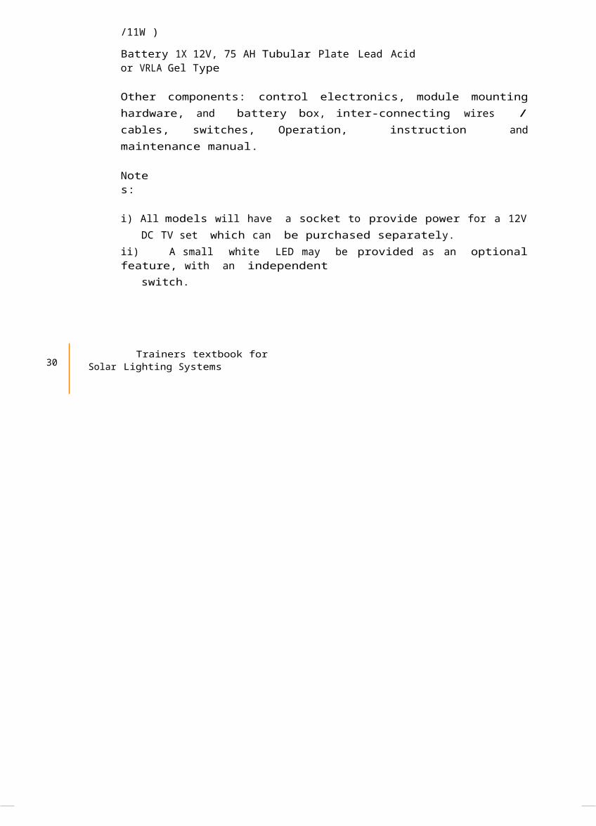
Notes:
i) All models will have a socket to provide power for a 12VDC TV set which can be purchased separately.
ii) A small white LED may be provided as an optionalfeature, with an independent
switch.
30 Trainers textbook for
Solar Lighting Systems
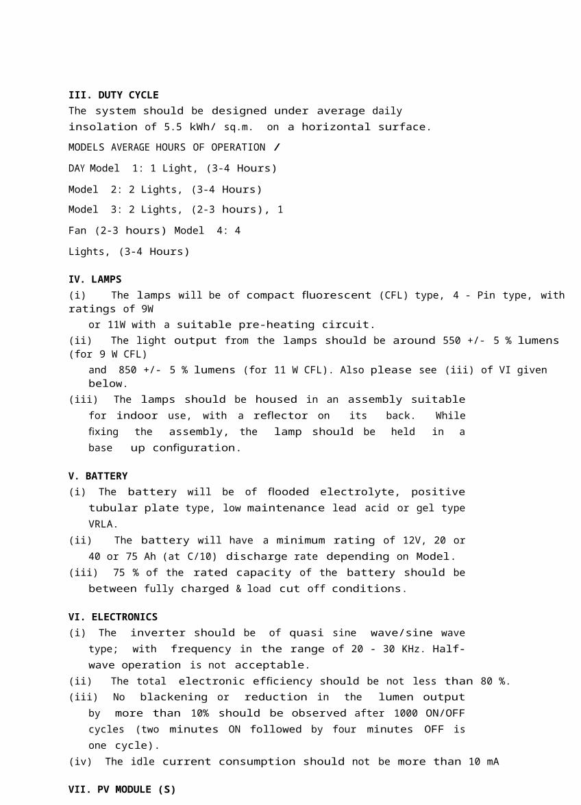
III. DUTY CYCLEThe system should be designed under average daily insolation of 5.5 kWh/ sq.m. on a horizontal surface.
MODELS AVERAGE HOURS OF OPERATION /
DAY Model 1: 1 Light, (3-4 Hours)
Model 2: 2 Lights, (3-4 Hours)Model 3: 2 Lights, (2-3 hours), 1
Fan (2-3 hours) Model 4: 4
Lights, (3-4 Hours)
IV. LAMPS(i) The lamps will be of compact uofl rescent (CFL) type, 4 - Pin type, with ratings of 9W
or 11W with a suitable pre-heating circuit.(ii) The light output from the lamps should be around 550 +/- 5 % lumens (for 9 W CFL)
and 850 +/- 5 % lumens (for 11 W CFL). Also please see (iii) of VI given below.
(iii) The lamps should be housed in an assembly suitablefor indoor use, with a re ector fl on its back. Whilexing fi the assembly, the lamp should be held in abase up con gufi ration.
V. BATTERY(i) The battery will be of oodedfl electrolyte, positive
tubular plate type, low maintenance lead acid or gel typeVRLA.
(ii) The battery will have a minimum rating of 12V, 20 or40 or 75 Ah (at C/10) discharge rate depending on Model.
(iii) 75 % of the rated capacity of the battery should bebetween fully charged & load cut off conditions.
VI. ELECTRONICS(i) The inverter should be of quasi sine wave/sine wave
type; with frequency in the range of 20 - 30 KHz. Half-wave operation is not acceptable.
(ii) The total electronic ef ciencyfi should be not less than 80 %.(iii) No blackening or reduction in the lumen output
by more than 10% should be observed after 1000 ON/OFFcycles (two minutes ON followed by four minutes OFF isone cycle).
(iv) The idle current consumption should not be more than 10 mA
VII. PV MODULE (S)
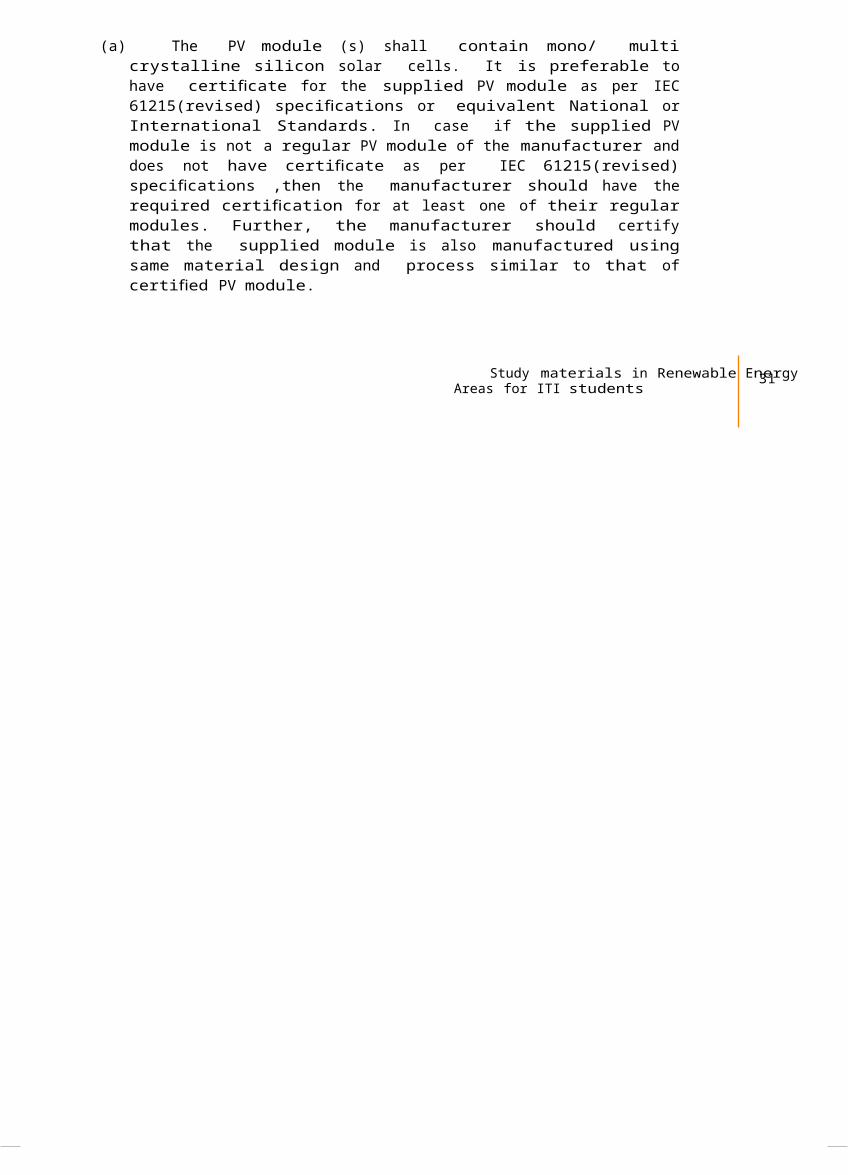
(a) The PV module (s) shall contain mono/ multicrystalline silicon solar cells. It is preferable tohave certi catefi for the supplied PV module as per IEC61215(revised) speci cationsfi or equivalent National orInternational Standards. In case if the supplied PVmodule is not a regular PV module of the manufacturer anddoes not have certi catefi as per IEC 61215(revised)speci cationsfi ,then the manufacturer should have therequired certi cationfi for at least one of their regularmodules. Further, the manufacturer should certifythat the supplied module is also manufactured usingsame material design and process similar to that ofcerti edfi PV module.
Study materials in Renewable EnergyAreas for ITI students 31
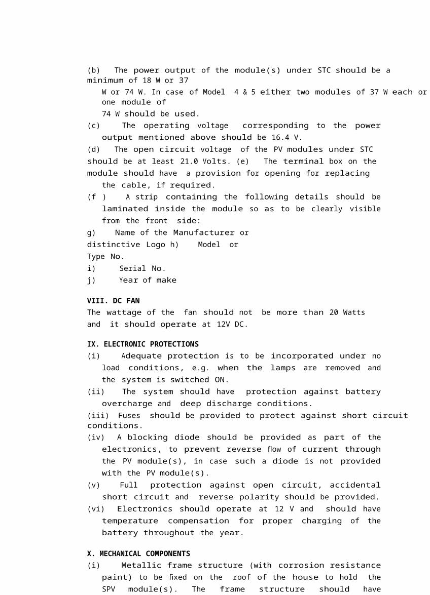
(b) The power output of the module(s) under STC should be a minimum of 18 W or 37
W or 74 W. In case of Model 4 & 5 either two modules of 37 W each orone module of74 W should be used.
(c) The operating voltage corresponding to the poweroutput mentioned above should be 16.4 V.
(d) The open circuit voltage of the PV modules under STC should be at least 21.0 Volts. (e) The terminal box on the module should have a provision for opening for replacing
the cable, if required.(f ) A strip containing the following details should be
laminated inside the module so as to be clearly visiblefrom the front side:
g) Name of the Manufacturer or distinctive Logo h) Model or Type No.i) Serial No.j) Year of make
VIII. DC FANThe wattage of the fan should not be more than 20 Watts and it should operate at 12V DC.
IX. ELECTRONIC PROTECTIONS(i) Adequate protection is to be incorporated under no
load conditions, e.g. when the lamps are removed andthe system is switched ON.
(ii) The system should have protection against batteryovercharge and deep discharge conditions.
(iii) Fuses should be provided to protect against short circuit conditions.(iv) A blocking diode should be provided as part of the
electronics, to prevent reverse flow of current throughthe PV module(s), in case such a diode is not providedwith the PV module(s).
(v) Full protection against open circuit, accidentalshort circuit and reverse polarity should be provided.
(vi) Electronics should operate at 12 V and should havetemperature compensation for proper charging of thebattery throughout the year.
X. MECHANICAL COMPONENTS(i) Metallic frame structure (with corrosion resistance
paint) to be xedfi on the roof of the house to hold theSPV module(s). The frame structure should have
provision to adjust its angle of inclination to thehorizontal between 0 and 45, so that it can beinstalled at the speci edfi tilt angle.
(ii) A vented metallic/ plastic box with acid proofcorrosion resistance paint for housing the storagebattery indoors should be provided.
XI OTHER FEATURES(i) The system should be provided with 2 LED
indicators: a green light to indicate charging inprogress and a red LED to indicate deep dischargecondition of the battery. The green LED should glow onlywhen the battery is actually being charged.
32 Trainers textbook for
Solar Lighting Systems
(ii) There will be a Name Plate on the system which will give: (a) Name of the Manufacturer or Distinctive Logo.(b) Serial Number.
(iii) Components and parts used in solar home systemsshould conform to the latest BIS
speci cationfi s, wherever such speci cationsfi are available and applicable.(iv) PV module(s) will be warranted for a minimum period
of 15 years from the date of supply and the solarhome system (including the battery) will be warrantedfor a period of two years from the date of supply.The Warranty Card to be supplied with the system mustcontain the details of the system supplied, as givenin the Annexure-12. The manufacturers can also provideadditional information about the system and conditionsof warranty as necessary.
4.3.2 Solar StreetLighting SystemI.DEFINITIONA stand alone solar photovoltaic street lighting systemcomprises a compact uofl rescent lamp, lead acid battery, PVmodule(s), control electronics, inter-connectingwires/cables, module mounting hardware, battery box,Operation, instruction and maintenance manual.
II. DUTYCYCLEThe system should be designed to automatically switch ON atdusk, operate throughout the night and automatically switch OFF at the down, under average daily insolation of5.5 kWh/ sq.m. on ahorizontal surface.
III.LAMP(i) The lamp will be of compact uofl rescent (CFL) of 11W, 4
- Pin type with adequate pre-heating circuit.(ii) The light output from the lamp should be around 850
+/- 5 % lumens. Also please see (iii) of V given below.(iii) The lamp should be housed in a weather proof
assembly suitable for outdoor use, with a re ectorfl onits back. While xingfi the assembly, the lamp should beheld in a base up con gufi ration.
IV.BATTERY(i) Flooded electrolyte type, positive tubular plate, low
maintenance lead acid or gel type VRLA(ii) The battery will have a minimum rating of 12V, 75Ah (at C/10) discharge rate.(iii) 75 % of the rated capacity of the battery should be
between fully charged & load cut off conditions.
V. ELECTRONICS(i) The inverter should be of quasi sine wave/ sine wave
type, with frequency in the range of 20 - 30 KHz. Half-wave operation is not acceptable.
(ii) The total electronic ef ciencyfishould be not less than 80 %.
Study materials in Renewable EnergyAreas for ITI students 33
(iii) No blackening or reduction in the lumen outputby more than 10% should be observed after 1000 ON/OFFcycles (two minutes ON followed by four minutes OFF isone cycle).
(iv) The idle current consumption should not be more than 10 mA.(v) The PV module itself will be used to sense the ambient light level for switching ON
and OFF the lamp.
VI. PV MODULE (S)(i) The PV module (s) shall contain mono/ multi
crystalline silicon solar cells. It is preferable tohave certi catefi for the supplied PV module as per IEC61215(revised) speci cationsfi or equivalent National orInternational Standards. In case if the supplied PVmodule is not a regular PV module of the manufacturer anddoes not have certi catefi as per IEC 61215(revised)speci cationsfi ,then the manufacturer should have therequired certi cationfi for at least one of their regularmodules. Further, the manufacturer should certifythat the supplied module is also manufactured usingsame material design and process similar to that ofcerti edfi PV module
(ii) The power output of the module(s) under STC shouldbe a minimum of 74 W. Either two modules of minimum 37 Woutput each or one module of 74 W output should beused.
(iii) The operating voltage corresponding to the poweroutput mentioned above should be 16.4 V.
(iv) The open circuit voltage of the PV modules under STC should be at least 21.0 Volts. (v) The terminal box on the module should have a provision for opening for replacing
the cable, if required.(vi) A strip containing the following details should be
laminated inside the module so as to be clearly visiblefrom the front side:a) Name of the Manufacturer or distinctive Logo b) Model or TypeNo.c) Serial No. d) Yearof make
VII. ELECTRONIC PROTECTIONS(i) Adequate protection is to be incorporated under no
load conditions e.g. when the lamp is removed and thesystem is switched ON.
(ii) The system should have protection against batteryovercharge and deep discharge conditions.
(iii) Fuses should be provided to protect against short circuit conditions.(iv) A blocking diode should be provided as part of the
electronics, to prevent reverse flow of current throughthe PV module(s), in case such a diode is not providedwith the solar module(s).
(v) Full protection against open circuit, accidentalshort circuit and reverse polarity should be provided.
(vi) Electronics should operate at 12 V and should have temperaturecompensation for
proper charging of the battery throughout the year.
34 Trainers textbook for
Solar Lighting Systems
VIII MECHANICAL HARDWARE(i) A metallic frame structure (with corrosion resistance
paint) to be xedfi on the pole to hold the SPVmodule(s). The frame structure should have provision toadjust its angle of inclination to the horizontalbetween 0 and 45, so that the module(s) can be orientedat the speci edfi tilt angle.
(ii) The pole should be made of mild steel pipe with aheight of 4 metres above the ground level, aftergrouting and nal fi installation. The pole should havethe provision to hold the weather proof lamp housing.It should be painted with a corrosion resistant paint.
(iii) A vented, acid proof and corrosion resistantpainted metallic box for outdoor use should beprovided for housing the battery.
IX. OTHER FEATURES(i) The system should be provided with 2 LED
indicators: a green light to indicate charging inprogress and a red LED to indicate deep dischargecondition of the battery. The green LED should glow onlywhen the battery is actually being charged.
(ii) There will be a Name Plate on the system, which will give: (a) Name of theManufacturer or Distinctive Logo.(b) SerialNumber.
(iii) Components and parts used in the solar streetlighting systems should conform to the latest BISspeci cationfi s, wherever such speci cationsfi areavailable and applicable.
(iv) The PV module(s) will be warranted for a minimumperiod of 15 years from the date of supply and the streetlighting system (including the battery) will bewarranted for a period of two years from the date ofsupply.The Warranty Card to be supplied with the system mustcontain the details of the system. The manufacturerscan also provide additional information about thesystem and conditions of warranty as necessary.
(v) Necessary lengths of wires/cables and fuses should be provided(vi) An Operation, Instruction and Maintenance
Manual, in English and the local language, shouldbe provided with the solar street lighting system.
The following minimum details must be
provided in the Manual: (a) About
Photovoltaic(b) About solar home system - its components and expected performance(c) About PV module. (d) About CFL.(e) About battery.(f ) Clear instructions about mounting of PV module(s). (g) About electronics.(h) About charging and signi cancefi of indicators. (i) DO's and DONT's,(j) Clear instructions on regular maintenance and trouble shooting of solar home system. (h) Name and address of the person or service center to be contacted incase of failure
orcomplaint.
Study materials in Renewable EnergyAreas for ITI students 35
4.4 Speci cationsfi for LED based solarlighting systems
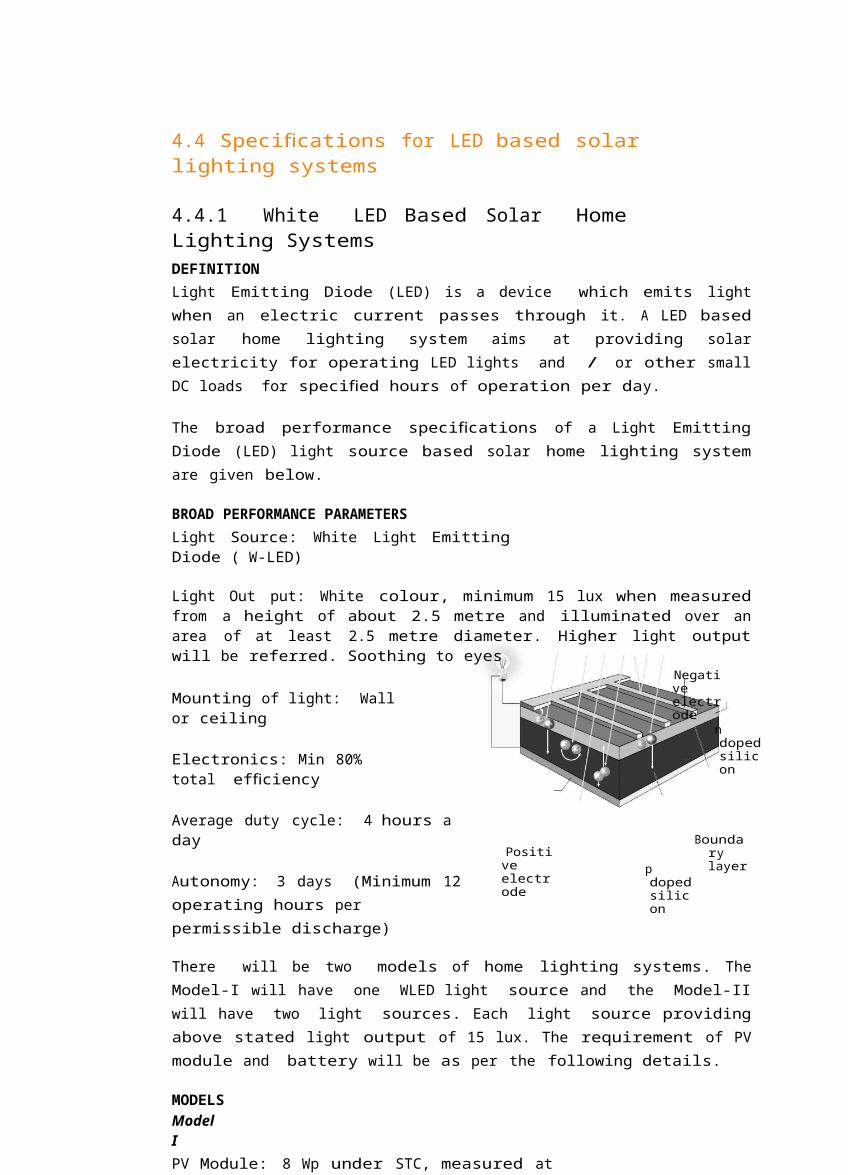
4.4.1 White LED Based Solar HomeLighting SystemsDEFINITIONLight Emitting Diode (LED) is a device which emits lightwhen an electric current passes through it. A LED basedsolar home lighting system aims at providing solarelectricity for operating LED lights and / or other smallDC loads for speci edfi hours of operation per day.
The broad performance speci cationsfi of a Light EmittingDiode (LED) light source based solar home lighting systemare given below.
BROAD PERFORMANCE PARAMETERSLight Source: White Light EmittingDiode ( W-LED)
Light Out put: White colour, minimum 15 lux when measuredfrom a height of about 2.5 metre and illuminated over anarea of at least 2.5 metre diameter. Higher light outputwill be referred. Soothing to eyes
Mounting of light: Wall or ceiling
Electronics: Min 80% total ef ciencyfi
Negative electrode
n dopedsilicon
Average duty cycle: 4 hours a day
Autonomy: 3 days (Minimum 12operating hours per permissible discharge)
Positive electrode
p dopedsilicon
Boundary layer
There will be two models of home lighting systems. TheModel-I will have one WLED light source and the Model-IIwill have two light sources. Each light source providingabove stated light output of 15 lux. The requirement of PVmodule and battery will be as per the following details.
MODELSModelIPV Module: 8 Wp under STC, measured at
16.4 V as VloadModule Voc minimum of 21 V
Battery Sealed maintenance free, 12 V- 7 AH @C/20, Max DoD 75%
ModelIIPV Module: 12 Wp under STC, measured at16.4 V as Vload
Module Voc minimumof 21 V
36 Trainers textbook for
Solar Lighting Systems
Battery: Lead acid oodedfl or VRLA, 12 V- 20 AH @
C/10, Max DoD 75% Other Details
DUTY CYCLEThe LED solar home lighting system should be designed to operate for average 4 hours a day, under average daily insolation of 5.5 kWh /sq.m. on a horizontal surface.
LIGHT SOURCE(i) The light source will be of white LED type. Single
lamp or multiple lamps can be used. View angles of aminimum of 1200 and above will be referred. Theluminous performance of LEDs used should not be lessthan 55 lumen/watt. The colour temperature of whiteLEDs used in the system should be in the range of 5500oK– 6500o K. Use of LEDs which emit ultraviolet light is not permitted.
(ii) The light output from the white LED light sourceshould be constant through out the duty cycle.
(iii) The lamps should be housed in an assembly suitable for indoor use.(iv) The make, model number, country of origin and
technical characteristics of white LEDs used in thelighting system must be furnished to the testcenters and to the buyers. In absence of this datathe solar lantern may not be tested by the testcenter.
BATTERY(i) Battery should conform to latest BIS standards or
international standards. A copy of the test certi catefifor the battery (including its make, country of originand model number) used in the system should beprovided to the test center.
(ii) At least 75 % of the rated capacity of the battery should be between fully charged &
load cut off conditions.
ELECTRONICS(i) The total electronic ef ciencyfi should be at least 80 %.(ii) Electronics should operate at 12 V and should have
temperature compensation for proper charging of thebattery through out the year.
(iii) The light output should remain constant with variations in the battery voltages.(iv) Necessary lengths of wires / cables, switches
suitable for DC use and fuses should be provided.
PV MODULE(a) The PV module based on crystalline (single or multi)
silicon solar cells or thin lms fi may be used. In allcases a test report is required from authorized testcenter. The PV module must be manufactured by acompany, which has obtained a valid test certi catefifor module quali cationfi as per prevailing IEC 62125 orBIS standards for any of the modules manufactured bythat company. A copy of the IEC certi cate fi must besubmitted to the test agency at the time ofsubmission of the samples for testing, failing whichthe sample may not be tested.
Study materials in Renewable EnergyAreas for ITI students 37
(b) The power out put of the PV module must bereported under standard test conditions (STC) at 16.4Volt loading voltage. I_V curve of the sample moduleshould be submitted to the test center at the time ofsystem quali cationfi testing.
(c) The open circuit voltage of the PV modules under STC should be at least 21.0 Volts. (d) The terminal box on the module should have a provision for opening for replacing
the cable, if required.(e) A strip containing the following details should be
laminated inside the module so as to be clearlyvisible from the front side:a) Name of the Manufacturer or distinctive Logo b) Model or TypeNo.c) Serial No. d) Yearof make
QUALITY AND WARRANTY(i) Components and parts used in White LED based solar
home lighting systems should conform to the latest BIS /international speci cationfi s, wherever suchspeci cations fi are available and applicable. A copy of thetest report / certi catefi stating conformity of BIS /international standards must be submitted to the testcentre.
(ii) The PV module will be warranted for a minimumperiod of 15 years from the date of supply and theWhite LED solar home system (excluding the battery)will be warranted for a period of at least 5 yearsfrom the date of supply. The sealed maintenance freebattery should be warranted for a period of at least twoyear. The lead acid oodedfl type battery or VRLA batteryshould be warranted for a period of 5 years.
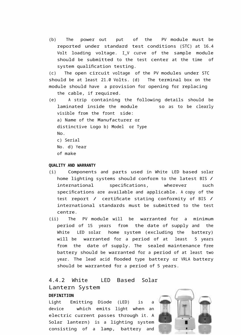
4.4.2 White LED Based SolarLantern SystemDEFINITIONLight Emitting Diode (LED) is adevice which emits light when anelectric current passes through it. ASolar lantern) is a lighting systemconsisting of a lamp, battery and
electronics, all placed in a suitablehousing, made of metal, plastic orber fi glass, and a PV module. Thebattery is charged by electricitygenerated through the PV module. Thelantern is basically a portablelighting device suitable for eitherindoor or outdoor lighting, coveringa full range of 360 degrees. A LEDbased solar lantern system aims atproviding solar electricity foroperating LED lights for speci edfi hoursof operation per day.
The broad performance speci cationsfi of a white Light Emitting Diode (LED) light source based solar lantern system are given below.
BROAD PERFORMANCE PARAMETERSLight Source: White Light Emitting Diode ( W-LED),dispersed, soothing to eyes
38 Trainers textbook for
Solar Lighting Systems
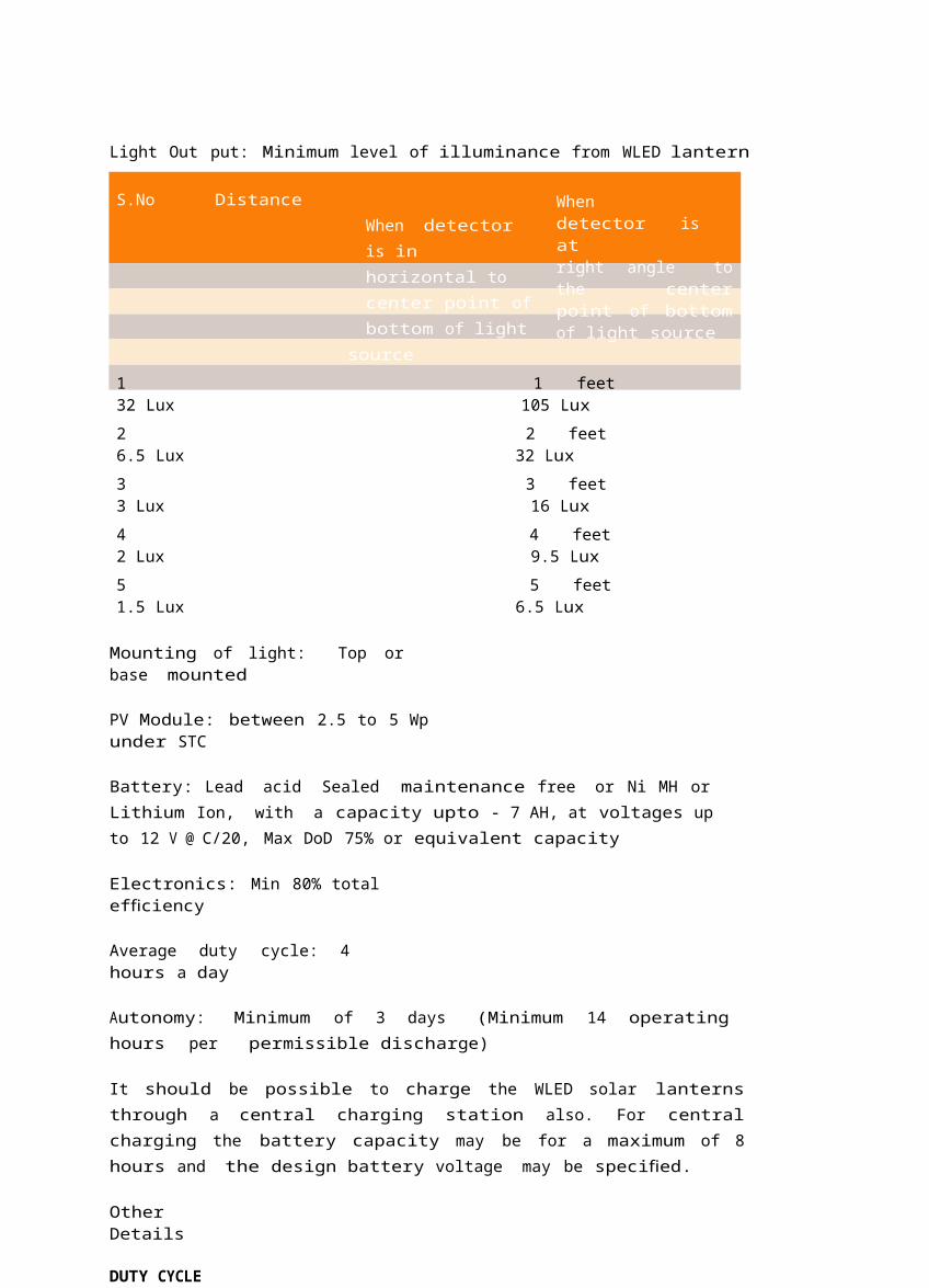
Light Out put: Minimum level of illuminance from WLED lantern
S.No Distance When detector is in horizontal to center point ofbottom of light
source
Whendetector isatright angle tothe centerpoint of bottomof light source
1 1 feet32 Lux 105 Lux2 2 feet6.5 Lux 32 Lux3 3 feet3 Lux 16 Lux4 4 feet2 Lux 9.5 Lux5 5 feet1.5 Lux 6.5 Lux
Mounting of light: Top orbase mounted
PV Module: between 2.5 to 5 Wpunder STC
Battery: Lead acid Sealed maintenance free or Ni MH or Lithium Ion, with a capacity upto - 7 AH, at voltages up to 12 V @ C/20, Max DoD 75% or equivalent capacity
Electronics: Min 80% totalef ciencyfi
Average duty cycle: 4hours a day
Autonomy: Minimum of 3 days (Minimum 14 operating hours per permissible discharge)
It should be possible to charge the WLED solar lanternsthrough a central charging station also. For centralcharging the battery capacity may be for a maximum of 8hours and the design battery voltage may be speci ed.fi
OtherDetails
DUTY CYCLE
The LED solar lantern system should be designed to operatefor average 4 hours a day, under average daily insolation of 5.5 kWh /sq.m. on a horizontal surface.
LIGHT SOURCEThe light source will be of white LED type. Single lamp ormultiple lamps can be used. Wider view angles preferred.The luminous performance of LEDs used should not be lessthan 55 lumen/watt. White colour, higher light output willbe preferred. The colour temperature of white LEDs used inthe system should be in the range of 5500o K – 6500o K. Use ofLEDs which emit ultraviolet light is not permitted.
The light output from the white LED light source should be constant though out the ty cycle.
Study materials in Renewable EnergyAreas for ITI students 39
The lamps should be housed in an assembly suitable for indoor and outdoor use. The make, model number, country of origin and
technical characteristics of white LEDs used in thelighting system must be furnished to the testcenters and to the buyers. In absence of this datathe solar lantern may not be tested by the testcenter.
BATTERY(i) Sealed maintenance free battery. Battery should
conform to latest BIS standards or internationalstandards. A copy of the test certi catefi for thebattery (including its make, country of origin andmodel number) used in the system should be provided tothe test center and buyer.
(ii) At least 75 % of the rated capacity of the battery should be between fully charged &
load cut off conditions.
ELECTRONICS(i) The total electronic ef ciencyfi should be at least 80 %.(ii) Electronics should operate at 4.5/6/12 V and should
have temperature compensation for proper charging ofthe battery through out the year.
(iv) The light output should remain constant with variations in the battery voltages.(v) Necessary lengths of wires / cables, switches
suitable for DC use and fuses should be provided.
PV MODULE The PV modules based on crystalline silicon solar cells
or thin lmsfi may be used. In all cases a test report isrequired from authorized test center.
The power out put of the PV module must be reportedunder standard test conditions (STC) at loading voltage.I_V curve of the sample module should be submitted tothe test center at the time of system quali cationfitesting.
The open circuit voltage of the PV modules under STC should beat least ….. Volts. The terminal box on the module should have a provision
for opening for replacing the cable, if required. A strip containing the following details should be
laminated inside the module so as to be clearly visiblefrom the front side:
a) Name of the Manufacturer or distinctive Logo b) Model or TypeNo.c) Serial No. d) Yearof make
ELECTRONIC PROTECTIONS Adequate protection is to be incorporated under no load
conditions, e.g. when the lamps are removed and thesystem is switched ON.
The system should have protection against batteryovercharge and deep discharge conditions. Thenumerical values of the cut off limits must bespeci ed,fi while submitting the samples for the testingpurposes.
Fuses should be provided to protect against short circuit conditions.
40 Trainers textbook for
Solar Lighting Systems
A blocking diode should be provided as part of theelectronics, to prevent reverse flow of current throughthe PV module(s), in case such a diode is not providedwith the PV module.
Full protection against open circuit, accidentalshort circuit and reverse polarity should be provided.
OTHER FEATURES(i) The system should be provided with 2 LED
indicators: a green light to indicate charging inprogress and a red LED to indicate deep dischargecondition of the battery. The green LED should glow onlywhen the battery is actually being charged.
(ii) There will be a Name Plate on thesystem body which will give:
Name of the Manufacturer or Distinctive Logo. Model Number Serial Number Year of manufacture
QUALITY AND WARRANTY(ii) Components and parts used in White LED solar
home lighting systems should conform to the latest BIS/ international speci cationfi s, wherever suchspeci cations fi are available and applicable. A copy of thetest report / certi catefi stating conformity of BIS /international standards must be submitted to the testcentre.
(iii) The PV module will be warranted for a minimum periodof 15 years from the date of supply and the White LEDsolar lantern system (excluding the battery) will bewarranted for a period of at least 5 years from the dateof supply. The battery should be warranted for a periodof at least two years.
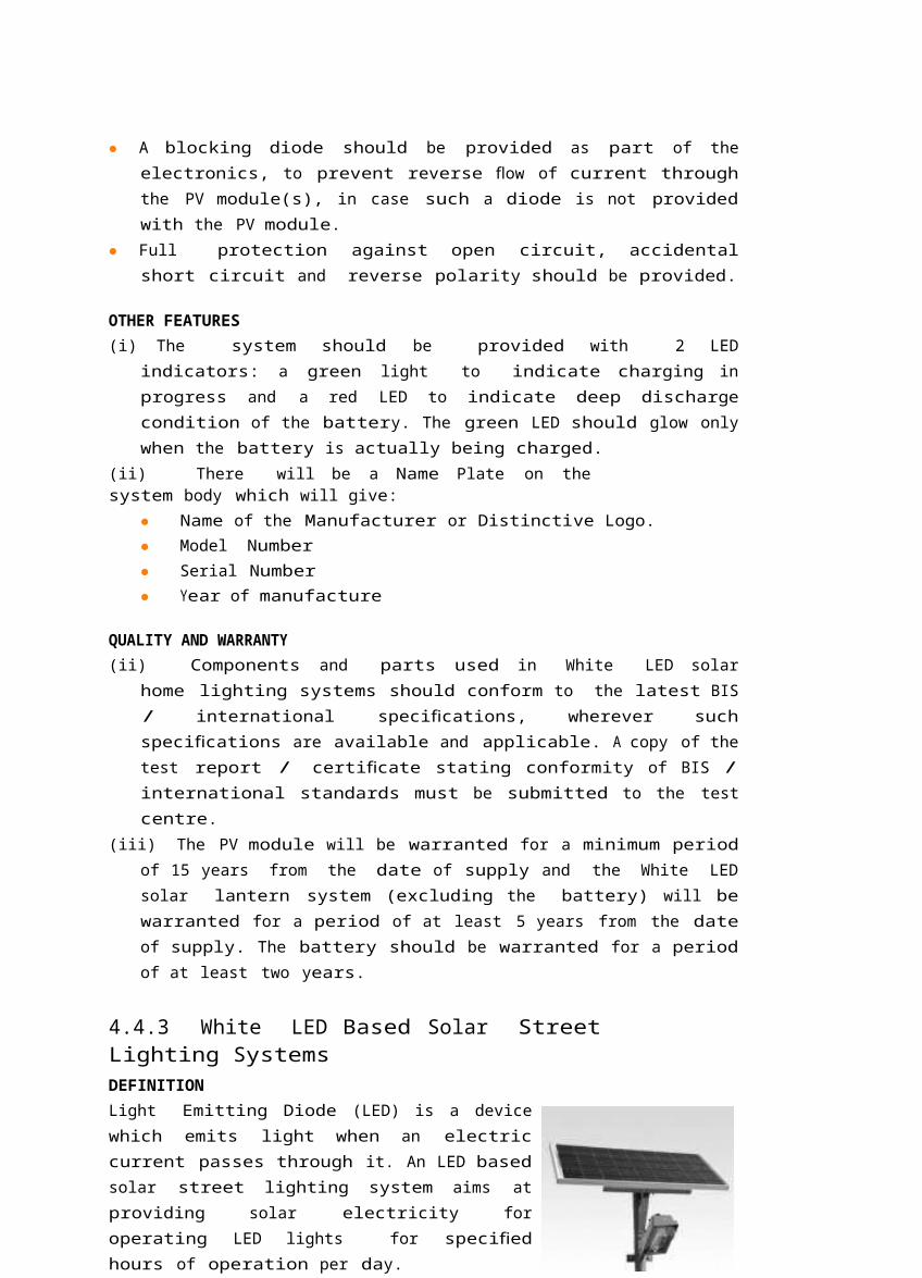
4.4.3 White LED Based Solar StreetLighting SystemsDEFINITIONLight Emitting Diode (LED) is a devicewhich emits light when an electriccurrent passes through it. An LED basedsolar street lighting system aims atproviding solar electricity foroperating LED lights for speci edfihours of operation per day.
The broad performance speci cationsfiof a White Light Emitting Diode (LED)light source based solar street lightingsystem are given below.
BROAD PERFORMANCE PARAMETERSLight Source: White Light EmittingDiode ( W-LED)
Light Out put: White colour, minimum 15 lux when measuredfrom a height of about 4 metre and illuminated over anarea of at least 4 metre diameter. Higher light outputwill be preferred.
Study materials in Renewable EnergyAreas for ITI students 41
Mounting of light: Minimum 4 metre pole Mounted
PV Module: 40 Wp under STC, measured at 16.4 V - VloadModule Voc minimum of 21 V
Battery: Tubular Lead acid, 12 V- 40 AH @
C/10, Max DoD 75% Electronics: Min 80%
total ef ciencyfi
Average duty cycle: Dusk to dawn
Autonomy: 3 days (Minimum 42 operating hours per
permissible discharge) Other Details
DUTY CYCLEThe LED solar street lighting system should be designed to operate for dust to dawn, under average daily insolation of 5.5 kWh /sq.m. on a horizontal surface.
LIGHT SOURCE1. The light source will be of white LED type. Single
lamp or multiple lamps can be used. Wider view anglesof a minimum of 120o and above preferred. The luminousperformance of LEDs used should not be less than 55lumen/watt. The colour temperature of white LEDs usedin the system should be in the range of 5500o K– 6500o K. Use of LEDs which emit ultraviolet light is not permitted.
2. The light output from the white LED light source shouldbe constant through out the duty cycle.
3. The lamps should be housed in an assembly suitable for outdooruse.4. The make, model number, country of origin and
technical characteristics of white LEDs used in thelighting system must be furnished to the test centersand to the buyers. In absence of this data the solarlantern may not be tested by the test center.
BATTERY(i) Tubular Lead acid battery. Battery should
conform to latest BIS standards or internationalstandards. A copy of the test certi catefi for thebattery (including its make, country of origin andmodel number) used in the system should be provided to
the test centre.(ii) At least 75 % of the rated capacity of the battery should be between fully charged &
load cut off conditions.
ELECTRONICS(i) The total electronic ef ciencyfi should be at least 80 %.(ii) Electronics should operate at 12 V and should have
temperature compensation for proper charging of thebattery through out the year.
(iii) The light output should remain constant with variations in thebattery voltages.(iv) Necessary lengths of wires / cables, switches
suitable for DC use and fuses should be provided.
42 Trainers textbook for
Solar Lighting Systems
PV MODULE1. The PV modules based on crystalline silicon (single
or multi) solar cells or thin lmsfi may be used. In allcases a test report is required from authorized testcenter. The module must be manufactured by a company,which has obtained a valid test certi catefi for modulequali cationfi as per prevailing IEC or BIS standards forany of the modules manufactured by that company. A copyof the IEC certi catefi must be submitted to the testagency at the time of submission of the samples fortesting of the system, failing which the sample may notbe tested.
2. The power out put of the PV module must bereported under standard test conditions (STC) at 16.4Volt loading voltage. I_V curve of the sample moduleshould be submitted to the test center at the time ofsystem quali cationfi testing.
3. The open circuit voltage of the PV modules under STC should be at least21.0 Volts.4. The terminal box on the module should have a provision
for opening for replacing the cable, if required.5. A strip containing the following details should be
laminated inside the module so as to be clearly visiblefrom the front side:a) Name of the Manufacturer or distinctive Logo b) Model or TypeNo.c) Serial No. d) Yearof make
ELECTRONIC PROTECTIONS1. The system should have protection against battery
overcharge and deep discharge conditions. Thenumerical values of the cut off limits must bespeci ed,fi while submitting the samples for the testingpurposes.
2. Fuses should be provided to protect against short circuit conditions.3. A blocking diode should be provided as part of the
electronics, to prevent reverse flow of current throughthe PV module(s), in case such a diode is not providedwith the PV module.
4. Full protection against open circuit, accidentalshort circuit and reverse polarity should be provided.
MECHANICAL COMPONENTS(i) Metallic frame structure (with corrosion resistance
paint) to be xedfi on the roof of the house to hold theSPV module. The frame structure should have provisionto adjust its angle of inclination to the horizontalbetween 0 and 45, so that it can be installed at thespeci edfi tilt angle.
(ii) It should be possible to mount the light source ona metallic arm attached to the pole. The metallic armfor holding the light assembly should be extended atleast 1.5 metres from the pole and set at a suitableangle to maximize uniform illumination of desired levelover the speci edfi area.
(Iii) A vented metallic / plastic box with acid proof corrosion resistance paint for housing
the storage battery outdoors should be provided.
Study materials in Renewable EnergyAreas for ITI students 43
OTHER FEATURES(i) The system should be provided with 2 LED
indicators: a green light to indicate charging inprogress and a red LED to indicate deep dischargecondition of the battery. The green LED should glow onlywhen the battery is actually being charged.
(ii) There will be a Name Plate on the system body which will give: (a) Name of the Manufacturer or Distinctive Logo.(b) Model Number(c) Serial Number (d) Year of manufacture
QUALITY AND WARRANTY(i) Components and parts used in White LED solar
street lighting systems should conform to the latestBIS / international speci cationfi s, wherever suchspeci cations fi are available and applicable. A copy of thetest report / certi catefi stating conformity of BIS/international standards must be submitted to the testcentre.
(ii) The PV module will be warranted for a minimum periodof 15 years from the date of supply and the completeWhite LED solar street lighting system (including thebattery) will be warranted for a period of at least 5years from the date of supply.
(iii) The original manufacturers of white LED basedsolar home lighting system are required to provide tothe test center a detailed report on the testsperformance by them and the actually measured valuesof PV module, electronics, LEDs and battery and otherrelated parameters, as per MNRE speci cationfi s. Meremention of compliance to MNRE speci cationsfi is notacceptable and such samples may not be tested by theTest center. The test center will refer to the measuredvalues providedby the manufacturer in the test report issued by the test center.
44 Trainers textbook for
Solar Lighting Systems
Unit 5: Maintenance and Troubleshooting
Time: 1hour
Method: demonstration,presentation
5.1 RoutineMaintenance
A solar electric system that is properly maintainedrequires very little maintenance. In fact the work involvedin maintaining a solar electric system is much less thanthat required to maintain a diesel or petrol poweredgenerator. The best maintenance practice is to makeregular inspections of the equipment (especially thebatteries and modules), to make sure that things arekept clean and all electrical contacts are tight.
5.1.1 BatterymaintenanceBatteries require regular and careful maintenance. Fora longer life batteries should:
Be cleanedmonthly Have theirelectrolyte level checked Be kept in a highstate of charge
5.1.2 Cleaning (oncea month)Carry the battery outside when cleaning to avoid spilling of acid. Keep water nearby to rinse spills.
Turn off or disconnectthe solar charge Disconnect the battery from the leads and remove
the terminals from the posts. Clean the top and outside of the battery with water
(do not allow water to enter the cells) Clean the terminals and the posts until they are shiny.
If the terminals are corroded (i.e. they are coveredwith a white power) clean them carefully with asolution of baking powder and water. If the terminalsare badly corroded then replace them.
Replace the cleaned terminals and tighten the bolts.Apply petroleum jelly or grease to the connectedterminals.
If unable to open the tight bolts, place wetcloth over it for 2-3 hours and then
open it.
Study materials in Renewable EnergyAreas for ITI students 45
5.1.3 Checking and Topping upElectrolyte level (monthly) Remove caps of each of the cells one at a time and check
the level of electrolyte. Acid level should be within twocentimeters of the top battery. If you can look insidethe battery, check the plates to see their condition
If the electrolyte level is down, add ionizeddistilled water till it is about two centimetersbelow the top of the battery.
DO NOT ADD RAINWATER COLLECTED IN METAL CONTAINERSDO NOT ADD ACID, TAP WATER OR TONICS TO THE BATTERY
5.1.4 Checking thestate of Charge
BE CAREFUL NOT TO USE LOW CHARGED BATTERIES If the battery is in the state of low charge, reduce the
use of load and allow the battery to be charged by amodule
With large systems (schools, hospitals) keep records ofthe battery, state of charge, age and performance. Thisallows users to judge more easily whether a batteryneeds replacement.
5.1.5 EqualisingChargeAn equalizing charge is a hard charge from a grid orgenerator powered battery charger that takes a battery abit above its normal full state. It causes bubbling whichmixes up the acid inside the battery, it also helpsremove accumulated sulphate from the battery during thecloudiest months of the year.
5.1.6 ModuleMaintenanceModules require minimum maintenance as they do not have anymoving parts. Keeping the glass surface clean is the mostimportant task. Dust and shade will reduce the electricoutput. Clean the module with water and if necessary amild soap. Do not allow a plant or a tree to shade thepanel
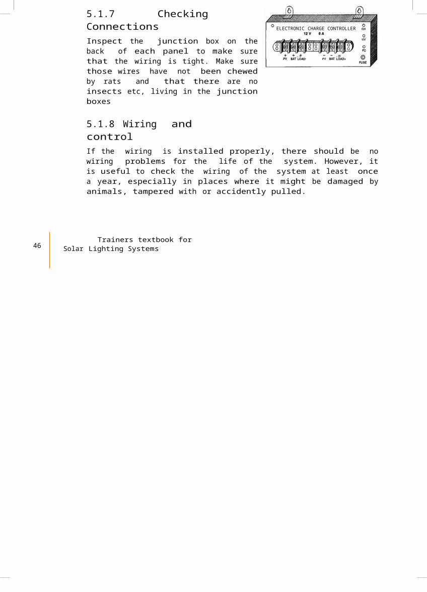
5.1.7 CheckingConnectionsInspect the junction box on theback of each panel to make surethat the wiring is tight. Make surethose wires have not been chewedby rats and that there are noinsects etc, living in the junctionboxes
ELECTRONIC CHARGE CONTROLLER
5.1.8 Wiring andcontrolIf the wiring is installed properly, there should be nowiring problems for the life of the system. However, itis useful to check the wiring of the system at least oncea year, especially in places where it might be damaged byanimals, tampered with or accidently pulled.
46 Trainers textbook for
Solar Lighting Systems
5.1.9 Inspecting wiring, fuses, indicator lamps and switches(annual) Check the tightness of al connector strips. Make sure that no bare wire is visible Inspect system wire runs for breaks, cracks in the
insulation or places it has been chewed up. This isespecially important for old or exposed wire
Inspect junction boxes to make sure that they have notbecome homes for insects. If they are in an exposedlocation, make sure that they are watertight.
Check the switch. It should not spark while turning ON or OFF. Check the indicator lamps on the control. The solar
charge comes ON when the sun is up. If it is not On,check to see if the batteries are being charged. Checkwhether other LED indicators are working.
Check the grounding wires to make sure that they are all intact.
5.1.10 Lamps and Other Loads On a daily basis one should operate the loads as
ef cientlyfi as possible. Maintenance of loads includesturning off lights and appliances when not in use.
Clean lamps, re ectorsfl and xtufi res once every fewmonths. Dust and dirt will reduce lamp output by as muchas 20%
Check for blackening of tubes in uofl rescent xtufi res and replace them Replace burnt out bulbs
5.2 Troubleshooting
Troubleshooting means facing problems as they occur.Although if the equipment is properly installed, systemsare unlikely to fail, some problems that need attendingto may arise.
The battery is the most likely source of problem in a small solar electric system
Basic problems:
What was the weather like in the days preceding theproblem? Has the weather been cloudy? Is it likelythat the load has been using more energy than themodules generate? If the latter is the case, then theproblem may be due to the misuse of the system or due
to failure of a component Is the system new? Do the users know about daily maintenance? What is the condition, type and age of the battery?
Can it still hold a charge? If it is old and corrodedchange it.
Whether the battery box is properly ventilated andpreventing the battery from high temperature?
Locate all the fuses in the system and see if theyhave blown. Check and see what caused the fuse to blow(i.e. short circuit, overload) before replacing it.
Are all the wires connected securely? Are they corroded? Is there any place where a
wire is likely tohave broken?
Study materials in Renewable EnergyAreas for ITI students 47
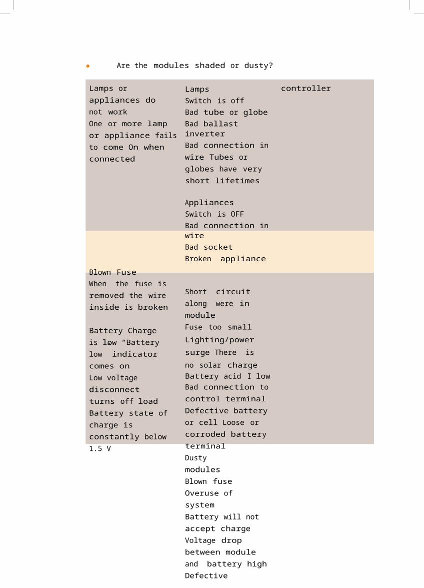
Are the modules shaded or dusty?
Lamps or appliances do not workOne or more lamp or appliance failsto come On when connected
Blown FuseWhen the fuse is removed the wire inside is broken
Battery Charge is low “Battery low” indicator comes onLow voltage disconnect turns off loadBattery state ofcharge is constantly below1.5 V
LampsSwitch is offBad tube or globeBad ballast inverterBad connection inwire Tubes or globes have very short lifetimes
AppliancesSwitch is OFFBad connection inwireBad socketBroken appliance
Short circuit along were in moduleFuse too small Lighting/power surge There is no solar chargeBattery acid I lowBad connection tocontrol terminalDefective batteryor cell Loose or corroded battery terminalDusty modules Blown fuse Overuse of systemBattery will notaccept chargeVoltage drop between module and battery highDefective
controller
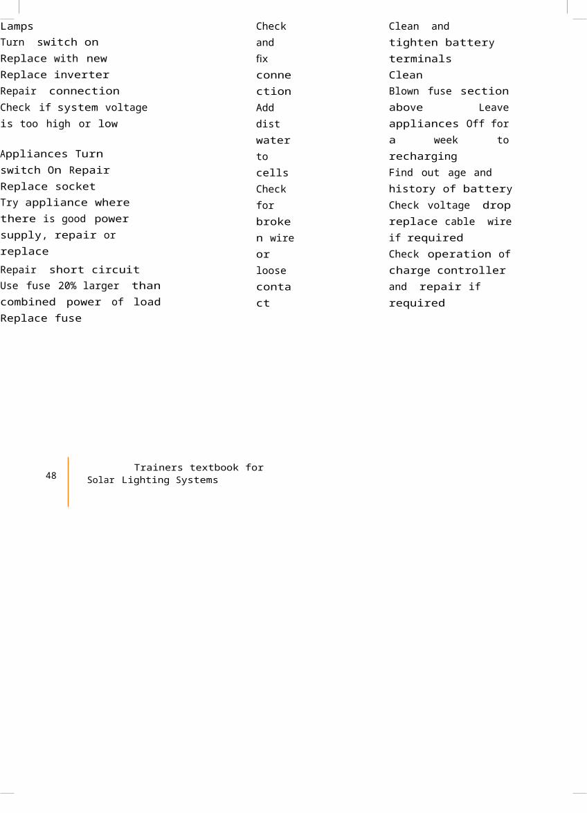
LampsTurn switch on Replace with new Replace inverter Repair connectionCheck if system voltage is too high or low
Appliances Turn switch On RepairReplace socketTry appliance where there is good power supply, repair or replaceRepair short circuitUse fuse 20% larger thancombined power of loadReplace fuse
Check and xfi connectionAdd dist waterto cells Check for broken wireor loose contact
Clean and tighten battery terminalsCleanBlown fuse sectionabove Leaveappliances Off fora week torechargingFind out age and history of batteryCheck voltage dropreplace cable wireif requiredCheck operation ofcharge controllerand repair ifrequired
48 Trainers textbook for
Solar Lighting Systems
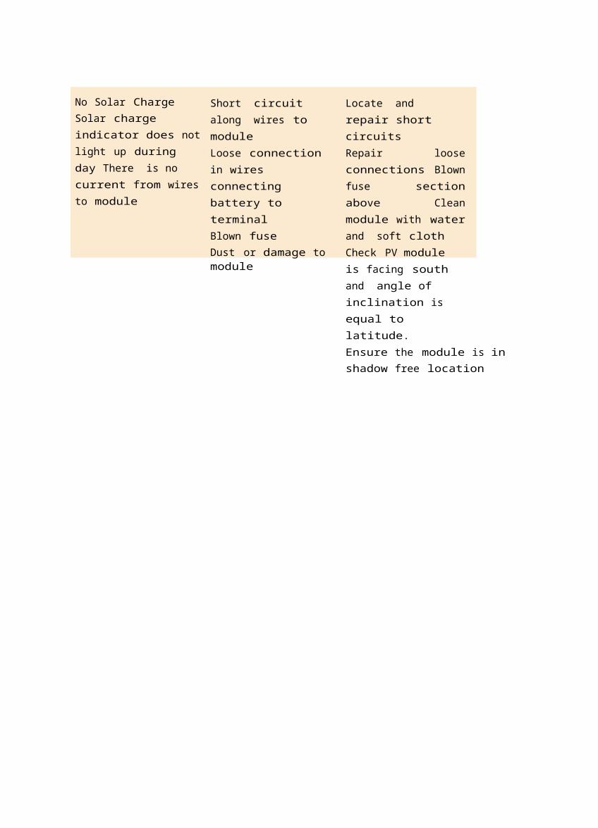
No Solar ChargeSolar charge indicator does notlight up during day There is no current from wiresto module
Short circuit along wires to moduleLoose connection in wires connecting battery to terminalBlown fuseDust or damage to module
Locate and repair short circuitsRepair looseconnections Blownfuse sectionabove Cleanmodule with waterand soft clothCheck PV module is facing south and angle of inclination is equal to latitude.Ensure the module is inshadow free location

Related Documents


![[DOCUMENT TITLE] PROPOSAL FOR SOLAR PHOTOVOLTAIC POWER ... · 125 MWp Solar Photovoltaic Power Plant for Manav Sewa Page 7 1. The Power Conditioner Unit (PCU) consisting of MPPT and](https://static.cupdf.com/doc/110x72/5ecdd99a1787110540482ed1/document-title-proposal-for-solar-photovoltaic-power-125-mwp-solar-photovoltaic.jpg)