Unit 1 Network Models and Network Examples

Unit 1 network models & typical examples(part a)
Aug 20, 2015
Welcome message from author
This document is posted to help you gain knowledge. Please leave a comment to let me know what you think about it! Share it to your friends and learn new things together.
Transcript
Unit 1
Network Modelsand
Network Examples

Unit 1 - Part ANetwork Models

Alternative definition of Network :
A network is a combination of hardware and software that sends data from one location to another.
• Hardware : The hardware consists of the physical equipment that carries signals from one point of the network to another.
• Software : The software consists of instruction sets that make possible the services that we expect from a network.

Sections in Part – A [ Network Models ]
Layered Tasks
OSI Model
~ Introduction
~ Layers in OSI Model
TCP / IP Model
Addressing

2-1 LAYERED TASKS
Understanding Layered Tasks . . . . . . . . . . .
* We use the concept of layers in our daily life.
* Example :
Consider two friends who communicate through postal mail.
[ i.e. one friend sends a letter to another friend ]

Example of sending a letter ( postal mail )

Some notable points from the previous example . . . . . .
Components - The three vital components in any communication
system are : Sender, Receiver and Carrier
Hierarchy - Layers do exist on both the sites and these layers are
arranged in particular order. In other words, a particular
hierarchy of layers exists. [ Order Matters ! ]
Services – Each layer at the sending site uses the services of the
layer immediately below it; while each layer at the receiving site
provides the services to the layer immediately above it.

2-2 a) THE OSI MODEL ( Introduction )
What is ISO ? Established in 1947, the International Standards Organization (ISO) is a multinational body dedicated to worldwide agreement on international standards.
What is OSI ? An ISO standard that covers all aspects of network communications is the Open Systems Interconnection (OSI) model. It was first introduced in the late 1970s.
ISO is the organization.OSI is the model.
Note

a) Layered Architecture
b) Peer-to-Peer Process
c) Encapsulation
Topics discussed in this introductory section:
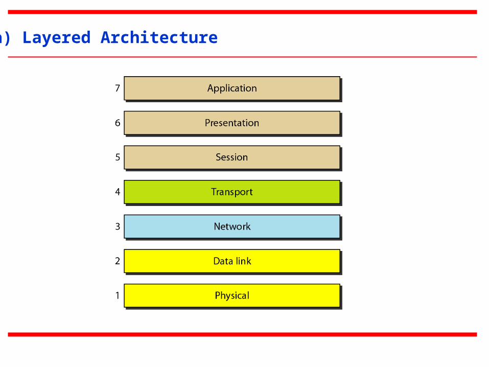
a) Layered Architecture

b) Peer-to-Peer Processes

c) Encapsulation
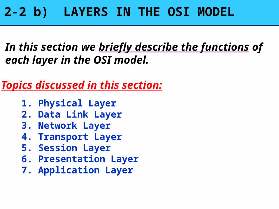
2-2 b) LAYERS IN THE OSI MODEL
In this section we briefly describe the functions of each layer in the OSI model.
1. Physical Layer2. Data Link Layer3. Network Layer4. Transport Layer5. Session Layer6. Presentation Layer7. Application Layer
Topics discussed in this section:

1) Physical layer
The physical layer is responsible for movements ofindividual bits from one hop (node) to the next.
Note

2) Data link layer
The data link layer is responsible for moving frames from one hop (node) to the next.
Note

Hop-to-hop delivery

3) Network layer
The network layer is responsible for the delivery of individual packets from
the source host to the destination host.
Note
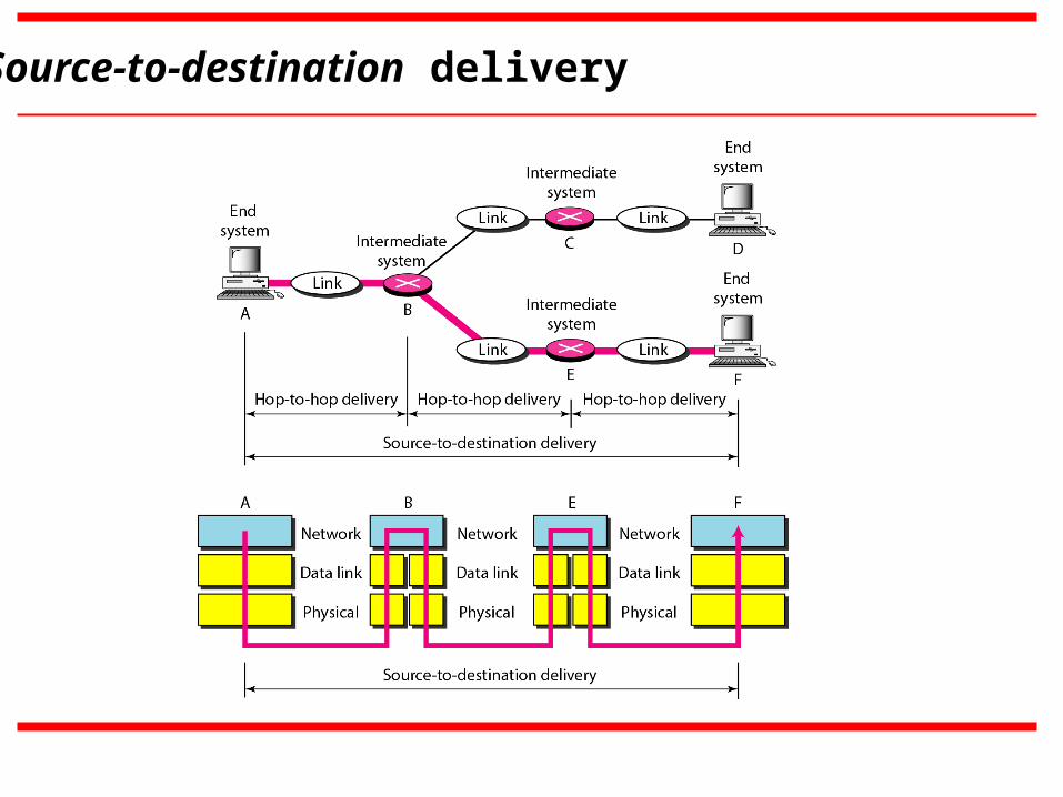
Source-to-destination delivery

4) Transport layer
The transport layer is responsible for the delivery of a message from one process to another process.
Note
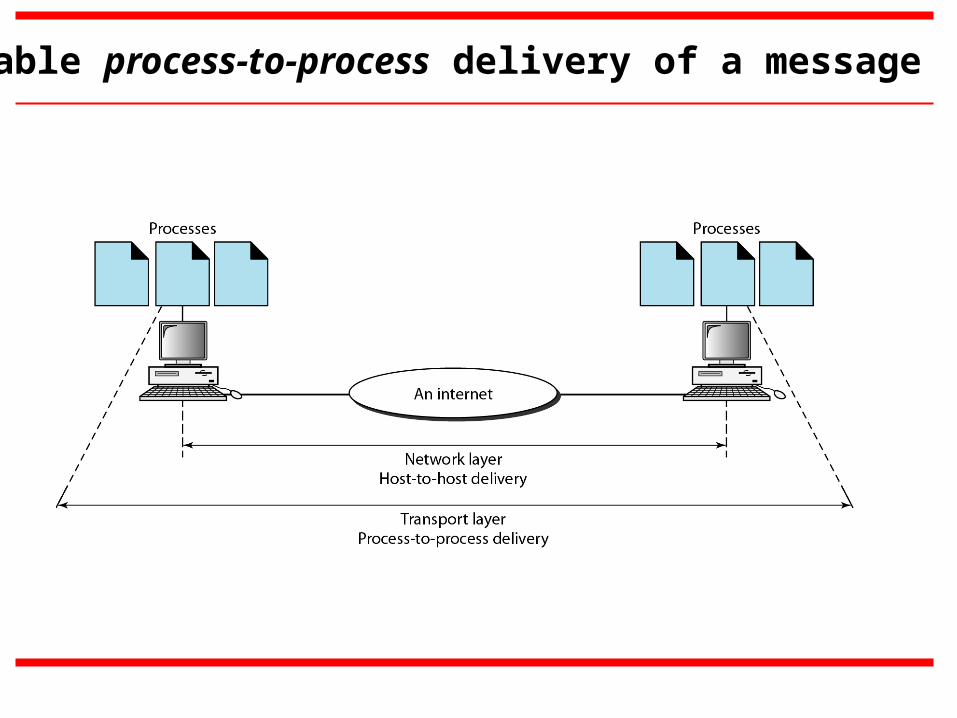
Reliable process-to-process delivery of a message

5) Session layer
The session layer is responsible for dialog control and synchronization.
Note

6) Presentation layer
The presentation layer is responsible for translation, compression, and encryption.
Note

7) Application layer
The application layer is responsible for providing services to the user.
Note

Summary of layers

2-4 TCP/IP PROTOCOL SUITE
The original TCP/IP protocol suite was defined as having four layers : host-to-network, network(internet), transport and application.

The layers in the TCP/IP protocol suite do not exactly match those in the OSI model.
However, when TCP/IP is compared to OSI, we can say that the TCP/IP protocol suite is made of five layers: physical, data link, network, transport, and application
[next slide . . . . ]

Assumed TCP/IP Model ( Internet Model ) in the text book :

Overlap of TCP/IP Model (Internet Model) and OSI model
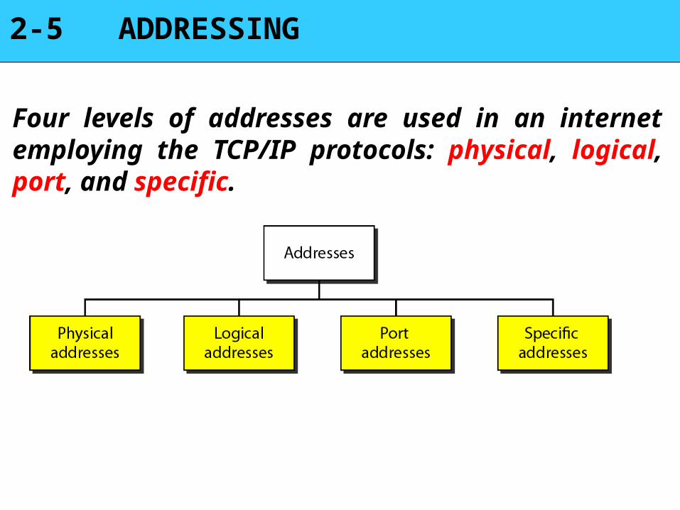
2-5 ADDRESSING
Four levels of addresses are used in an internet employing the TCP/IP protocols: physical, logical, port, and specific.

Relationship of layers and addresses in TCP/IP (Internet Model)

1. Physical Address :
The physical address, also known as the link address, is the address of the node as defined by its LAN or WAN.
~ It is included in the frame used by the data link layer.
~ It is the lowest-level address.

Example to understand physical address
In Figure below a node with physical address 10 sends a frame to a node with physical address 87. The two nodes are connected by a link (bus topology LAN). As the figure shows, the computer with physical address 10 is the sender, and the computer with physical address 87 is the receiver.
2. Logical Address :
A logical address in the Internet is currently 32-bit address that can uniquely define a host connected to the Internet.
~ No two publicly addressed and visible hosts on the Internet
can have the same IP address.
[ Note : IP address is typical example of Logical Address on present day Internet ]

Figure in the next slide shows a part of an internet with two routers connecting three LANs. Each device (computer or router) has a pair of addresses (logical and physical) for each connection. In this case, each computer is connected to only one link and therefore has only one pair of addresses. Each router, however, is connected to three networks (only two are shown in the figure). So each router has three pairs of addresses, one for each connection.
Example to understand logical address


3. Port Address :
In TCP / IP model, the label assigned to a process is called a port address.
~ A port in TCP / IP is 16-bits in length.

Figure in the next slide shows two computers communicating via the Internet. The sending computer is running three processes at this time with port addresses a, b, and c. The receiving computer is running two processes at this time with port addresses j and k. Process a in the sending computer needs to communicate with process j in the receiving computer. Note that although physical addresses change from hop to hop, logical and port addresses remain the same from the source to destination.
Example to understand port address


The physical addresses change from hop to hop,but the logical and port addresses usually remain the same.
Note
4. Specific Address :
User-friendly address designed at the level of application layer is known as specific address.
Example : ~ email address (e.g. [email protected] )
~ website address. ( e.g. www.flipkart.com )
Related Documents


