VI Semester Civil CE6602 Structural Analysis-II by Ms.S.Nagajothi AP / Civil Page 1 ( SRI VIDYA COLLEGE OF ENGINEERING & TECHNOLOGY VIRUDHUNAGAR QUESTION BANK DEPARTMENT: CIVIL SEMESTER: VI SUBJECT CODE / Name: CE 6602 / STRUCTURAL ANALYSIS-II UNIT 1- FLEXIBILITY METHOD PART - A (2 marks) 1. Find degree of indeterminacy of the following. (AUC Apr/May 2011) Degree of indeterminacy = No. of reactions – No. of condition equations = (3 + 2 + 3) – 3 = 5 2. Define kinematic redundancy. (AUC Apr/May 2011) When a structure is subjected to loads, each joint will undergo displacements in the form of translations and rotations. Kinematic redundancy of a structure means the number of unknown joint displacement in a structure. 3. Give the mathematical expression for the degree of static indeterminacy of rigid jointed plane frames. (AUC Nov/Dec 2011) Degree of static indeterminacy = (No. of closed loops x 3) – No. of releases 4. What are the properties which characterize the structure response by means of force- displacement relationship? (AUC Nov/Dec 2011) Each element of a flexibility matrix represents a displacement at a coordinate (i) due to a force at a coordinate (j). If the matrix of the structure is known, we know the behaviour of the structure. 5. What are the conditions to be satisfied for determinate structures and how are indeterminate structures identified? (AUC May/June 2012) Determinate structures can be solving using conditions of equilibrium alone (H = 0; V = 0; M = 0). No other conditions are required. Indeterminate structures cannot be solved using conditions of equilibrium because (H ≠ 0; V ≠ 0; M ≠ 0). Additional conditions are required for solving such structures. 6. Write down the equation for the degree of static indeterminacy of the pin-jointed frames, explaining the notations used. (AUC May/June 2012) Total indeterminacy = External indeterminacy + Internal indeterminacy External indeterminacy = No. of reactions – No. of equilibrium equations Internal indeterminacy = m 2 j 3 )

Welcome message from author
This document is posted to help you gain knowledge. Please leave a comment to let me know what you think about it! Share it to your friends and learn new things together.
Transcript

VI Semester Civil CE6602 Structural Analysis-II by Ms.S.Nagajothi AP / Civil Page 1
(
SRI VIDYA COLLEGE OF ENGINEERING & TECHNOLOGY VIRUDHUNAGAR
QUESTION BANK
DEPARTMENT: CIVIL SEMESTER: VI
SUBJECT CODE / Name: CE 6602 / STRUCTURAL ANALYSIS-II
UNIT 1- FLEXIBILITY METHOD
PART - A (2 marks)
1. Find degree of indeterminacy of the following. (AUC Apr/May 2011)
Degree of indeterminacy = No. of reactions – No. of condition equations
= (3 + 2 + 3) – 3
= 5
2. Define kinematic redundancy. (AUC Apr/May 2011)
When a structure is subjected to loads, each joint will undergo displacements in the form of
translations and rotations. Kinematic redundancy of a structure means the number of
unknown joint displacement in a structure.
3. Give the mathematical expression for the degree of static indeterminacy of rigid jointed
plane frames. (AUC Nov/Dec 2011)
Degree of static indeterminacy = (No. of closed loops x 3) – No. of releases
4. What are the properties which characterize the structure response by means of force-
displacement relationship? (AUC Nov/Dec 2011)
Each element of a flexibility matrix represents a displacement at a coordinate (i) due to a
force at a coordinate (j).
If the matrix of the structure is known, we know the behaviour of the structure.
5. What are the conditions to be satisfied for determinate structures and how are
indeterminate structures identified? (AUC May/June 2012)
Determinate structures can be solving using conditions of equilibrium alone (H = 0; V = 0;
M = 0). No other conditions are required.
Indeterminate structures cannot be solved using conditions of equilibrium because (H ≠ 0;
V ≠ 0; M ≠ 0). Additional conditions are required for solving such structures.
6. Write down the equation for the degree of static indeterminacy of the pin-jointed frames,
explaining the notations used. (AUC May/June 2012)
Total indeterminacy = External indeterminacy + Internal indeterminacy
External indeterminacy = No. of reactions – No. of equilibrium equations
Internal indeterminacy = m 2 j 3 )

VI Semester Civil CE6602 Structural Analysis-II by Ms.S.Nagajothi AP / Civil Page 2
7. Differentiate pin-jointed plane frame and rigid jointed plane frame. (AUC May/June 2013)
S.No Pin jointed plane frame Rigid jointed plane frame
1 The joints permit change of angle
between connected members.
The members connected at a rigid joint
with maintain the angle between them
even under deformation due to loads.
2 The joints are incapable of transferring
any moment to the connected members
and vice-versa.
Members can transmit both forces and
moments between themselves through
the joint.
3 The pins transmit forces between
connected members by developing shear.
Provision of rigid joints normally
increases the redundancy of the
structures.
8. Mention any two methods of determining the joint deflection of a perfect frame.
(AUC May/June 2013)
Unit load method
Virtual work method
Slope deflection method
Strain energy method
9. What are the requirements to be satisfied while analyzing a structure?
The three conditions to be satisfied are:
(i) Equilibrium condition
(ii) Compatibility condition
(iii) Force displacement condition
10. What is meant by force method in structural analysis?
A method in which the forces are treated as unknowns is known as force method.
The following are the force methods:
Flexibility matrix method
Consistent deformation method
Claypeyron’s 3 moment method
Column analogy method
11. Define flexibility coefficient.
It is defined as the displacement at coordinate i due to unit force at coordinate j in a
structure. It makeup the elements of a flexibility matrix.
12. Why is flexibility method also called as compatibility method or force method?
Flexibility method begins with the superposition of forces and is hence known as force
method. Flexibility method leads to equations of displacement compatibility and is hence known as
compatibility method.
13. Define the Force Transformation Matrix.
The connectivity matrix which relates the internal forces Q and the external forces R is known
as the force transformation matrix. Writing it in a matrix form,
{Q} = [b] {R}
Where, Q = member force matrix/vector; b = force transformation matrix
R = external force/load matrix/ vector
VI Semester Civil CE6602 Structural Analysis-II by Ms.S.Nagajothi AP / Civil Page 3
14. State any two methods of matrix inversion.
Adjoint method
The gauss-jordan method (by linear transformation)
The Choleski method (by factorization)
Partitioning method
15. Define Degree of Freedom and explain its types.
Degree of freedom is defined as the least no of independent displacements required to
define the deformed shape of a structure.
There are two types of DOF: (a) Nodal type DOF and (b) Joint type DOF.
a) Nodal type DOF:
This includes the DOF at the point of application of concentrated load or moment, at a
section where moment of inertia changes, hinge support, roller support and junction of two or
more members.
b) Joint type DOF:
This includes the DOF at the point where moment of inertia changes, hinge and roller
support and junction of two or more members.
16. Define a primary structure.
A structure formed by the removing the excess or redundant restraints from an
indeterminate structure making it statically determinate is called primary structure. This is
required for solving indeterminate structures by flexibility matrix method.
17. Briefly mention the two types of matrix methods of analysis of indeterminate structures.
Flexibility matrix method:
This method is also called the force method in which the forces in the structure are treated
as unknowns. The no of equations involved is equal to the degree of static indeterminacy of the
structure.
Stiffness matrix method:
This is also called the displacement method in which the displacements that occur in the
structure are treated as unknowns. The no of displacements involved is equal to the no of
degrees of freedom of the structure.
19. Define local and global coordinates.
Local coordinates:
Coordinates defined along the individual member axes locally.
Global coordinates:
Common coordinate system dealing with the entire structure. Also known as system
coordinates.
20. What is the relation between the flexibility matrix and stiffness matrix?
The relation between the flexibility matrix and stiffness matrix is that, one is the inverse of
the other, when they both exist.

VI Semester Civil CE6602 Structural Analysis-II by Ms.S.Nagajothi AP / Civil Page 4
w 100 x 3 37.5 kN
w 100 x 3 37.5 kNm
w 60 x 4 80 kNm
2
w 60 x 4 80 kNm
2
PART - B (16 marks)
1. Analyse the continuous beam shown in figure using force method. (AUC Apr/May 2011)
Solution:
Step1: Static Indeterminacy :
Degree of redundancy = ( 1 + 1 + 3 ) - 3 = 2
Release at B and C by apply hinge.
Step 2: Fixed End Moment :
MFAB
MFBA
MFBC
MFBC
m 8 8
8 8 2
12 12 2
12 12
Step 3: Equivalent Joint Load:

VI Semester Civil CE6602 Structural Analysis-II by Ms.S.Nagajothi AP / Civil Page 5
1 0 2 0
1 2
0 0
1
L
0 0 2
1 2 0 0
1 0.5 1
0.5 0 1 0
0 0
0.67 0 0 1.33
0.67 0 0 1.33
1 0
1 0 0 0
0 1 and B
X 0 0 1 0
0 0 0 1
1 0
1 0 0 0
0 1
0 0 1 0
0 0 0 1
0.5 0 1 0 0 0
0.5 1 0 0 1 0 1 1 0 0
0.67
1
0 0 0 1 0 0 1.33 1 0
0.67 0 0 1.33 0 1
1 0
0 0
1 1.33 0.67 0.5 1
0 0 0.67 1.33 1 0
0 1
0.67 2.33
0.67 1.33
1 0.502 0.253
EI
0.253 0.879
efficient
BW
BX
BT
F B x
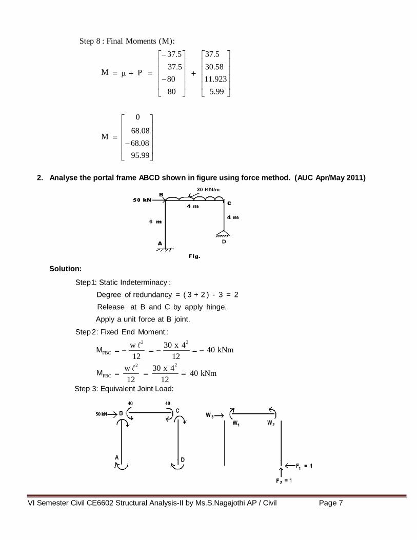
Step 4: Flexibility co matrix ( B ) :
B
BW
B
Step 5: Flexibility matrix (F) :
F 6 EI
F EI
FX x
EI
EI
F 1
x EI
Fx

VI Semester Civil CE6602 Structural Analysis-II by Ms.S.Nagajothi AP / Civil Page 6
0.5 0 1 0 1 0
0.5 1
0 0 0 1 1 1 0 0
0.67
1
0 0 0 1 0 0 1.33 0 0
0.67 0 0 1.33 0 0
1 0
0 1 1 1.33 0.67 0.5 1
0 0 0.67 1.33 0 0
0 0
1 0.5 1
0 0
1 37. 0.502 0.253 0.5 5 EI
0.253 0.879 0 0 42.5
0.502 0.251 37.5
0.127 0.253 42.5
11.923
5.99
1 F F
x W
11.923
5.99
1 0
1 0 0 0 37.5
0 1 42.5 W B
X 0 0 1 0 11.923
0 0 0 1 5.99
37.5
30.58
11.923
5.99
BT
F B x
FW w
EI
EI
FW
EI
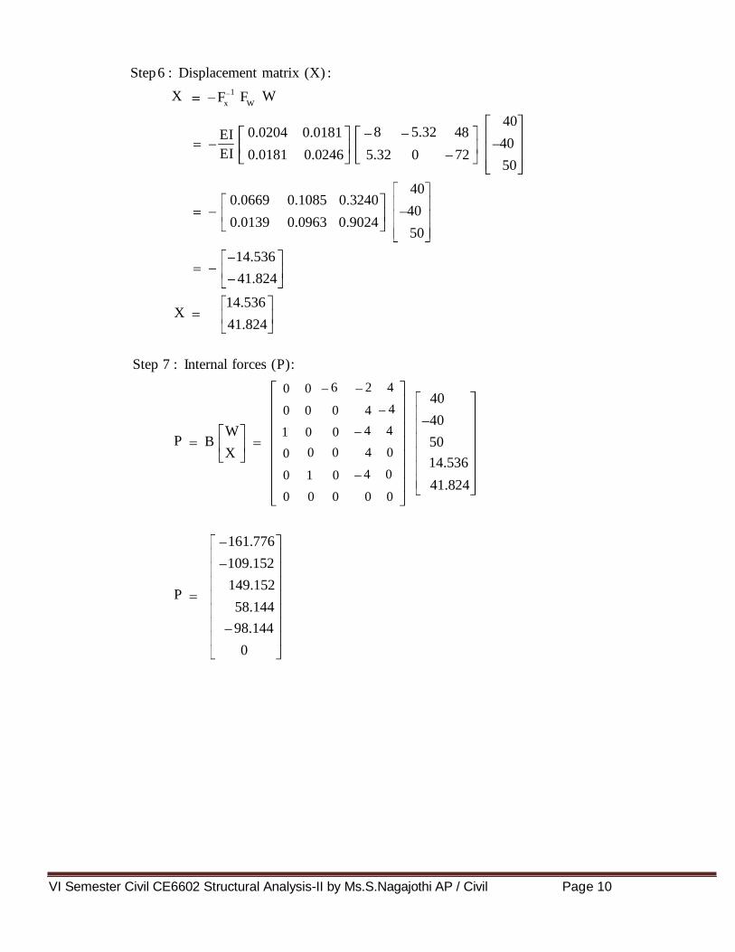
Step 6 : Displacement matrix (X) :
X W
EI
X
Step 7 : Internal forces (P):
P
P
VI Semester Civil CE6602 Structural Analysis-II by Ms.S.Nagajothi AP / Civil Page 7
37.5 37.5
37.5 30.58 P
80 11.923
80 5.99
0
68.08
68.08
95.99
w 30 x 4 2
w 30 x 4 40 kNm
2
40 kN
Step 8 : Final Moments (M):
M
M
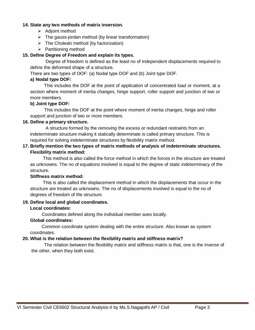
2. Analyse the portal frame ABCD shown in figure using force method. (AUC Apr/May 2011)
Solution:
Step1: Static Indeterminacy :
Degree of redundancy = ( 3 + 2 ) - 3 = 2
Release at B and C by apply hinge.
Apply a unit force at B joint.
Step 2: Fixed End Moment :
2
MFBC 12 12
m
2
MFBC
12 12
Step 3: Equivalent Joint Load:
VI Semester Civil CE6602 Structural Analysis-II by Ms.S.Nagajothi AP / Civil Page 8
6 2 4 0 0
4
4 4
0 0 0 4
1 0 0 and B
X
4 0
0 0 0 4 0
0 1 0
0 0 0 0 0
6 2 4 0 0
4
0 0 0 4
4 4 1 0 0
4 0
0 0 0 4 0
0 1 0
0 0 0 0 0
1 0 2 0 0 0
1 2
0 0 0 0
1 0 0 0 2 0 L
1 2
1
0 0 0 0
0 0 0 0 2
1 2 0 0 0 0
1 0 2 0 0 0
1 2
0 0 0 0
0.67 0 0 0 1.33 0 1
0.67
0.67
0 0 1.33 0 0
0 0 0 0 1.33
0.67 0 0 0 0 1.33
efficient
BW
BX
BT
F B x
Step 4: Flexibility co matrix ( B ) :
B
BW
B
Step 5: Flexibility matrix (F) :
F 6 EI
F EI
FX x

VI Semester Civil CE6602 Structural Analysis-II by Ms.S.Nagajothi AP / Civil Page 9
1 0 0 0 0 2 4 2
1 2 0 0 0 0 4 4
0.67 0 0 4 4 0 0 1.33 2 4 4 4 4 0 1
0.67
4 4 4 0 0 0 0 0
0.67 4 0
1.33 0 0 4 0
0 0 0 0 1.33
0.67 0 0 0 0 1.33 0 0
4 4 8 10 8 8 5.32 2.68 1
12 12 5.32 2.68 0 0 4 0
4 0
2 4
4
4
0 0
104 141.28 1
104 117.28
1 E
0.0204 0.0181 I
0.0181 0.0246
1 0 0 0 0 0 0 6 2
1 2
0 0 0 0 0 0 0
0.67 0 0 0 1.33 0 1 0 0 2 4 4 4 4 0 1
0.67
4 4 4 0 0 0 0 0
0.67
1.33 0 0 0 0 0
0 0 0 0 1.33 0 1 0
0.67 0 0 0 0 1.33 0 0 0
8 10 8 8 5.32 2.68 1 0 0 1
12 12 5.32 2.68 0 0 0 0 0
6 0 0
0 0 0
0 1 0
0 0 0
8 5.32 4 8 1
5.32 0 72
BT
F B x
EI
EI
Fx
EI
Fx
FW w
EI
EI
FW
EI
VI Semester Civil CE6602 Structural Analysis-II by Ms.S.Nagajothi AP / Civil Page 10
40 8 5.32 4 0.0204 0.0181 8
40 EI
0.0181 0.0246 5.32 0 72
50
1 F F
x W
40 0.0669 0.1085 0.3240
40
0.0139 0.0963 0.9024
50
14.536
41.824
14.536
41.824
6 2 4 0 0
4 40
0 0 0 4
40 4 4 1 0 0 W
50 B
X 0
4 0
0 0 4 0 14.536
0 1 0 41.824
0 0 0 0 0
161.776
109.152
149.152
58.144
98.144
0
Step 6 : Displacement matrix (X) :
X W
EI
X
Step 7 : Internal forces (P):
P
P

VI Semester Civil CE6602 Structural Analysis-II by Ms.S.Nagajothi AP / Civil Page 11
161.776 0
0 109.152
40 149.152 P
40 58.144
0 98.144
0 0
161.776
109.152
109.152
98.144
98.144
0
w 2 x 6 6 kNm
2
w 2 x 6 6 kNm
2
w 10 x 4 5 kNm
w 10 x 4 5 kNm
Step 8 : Final Moments (M):
M
M
3. Analyse the continuous beam ABC shown in figure by flexibility matrix method and
sketch the bending moment diagram. (AUC Nov/Dec 2011).
Solution:
Step1: Static Indeterminacy :
Degree of redundancy = ( 1 + 1 + 3 ) - 3 = 2
Release at B and C by apply hinge.
Step 2: Fixed End Moment :
2
MFAB 12 12
2
MFBA
MFBC
MFCB
12 12
8 8
8 8

VI Semester Civil CE6602 Structural Analysis-II by Ms.S.Nagajothi AP / Civil Page 12
1 0 2 0
1 2
0 0
1
L
0 0 2
1 2 0 0
1 1 2
1 0 2 0
0 0
0.67 0 0 1.33
0.67 0 0 1.33
1 0
1 0 0 0
0 0 and B
X 0 1 1 0
0 0 0 1
1 0
1 0 0 0
0 0
0 1 1 0
0 0 0 1
efficient
BW
BX
BT
F B x
Step 3: Equivalent Joint Load:
Step 4: Flexibility co matrix ( B ) :
B
BW
B
Step 5: Flexibility matrix (F) :
F 6 EI
F EI
FX x

VI Semester Civil CE6602 Structural Analysis-II by Ms.S.Nagajothi AP / Civil Page 13
1 0 2 0 0 0
1 2 0 0 1 0 1 1 0 0
0.67
1
0 0 0 1 0 0 1 .33 1 0
0.67 0 0 1.33 0 1
1 0
0 0
2 1.33 0.67 1 1
0 0 0.67 1.33 1 0
0 1
0.67 3.33 1
0.67 1.33
1 E
0.334 0.168 I
0.168 0.837
1 0 2 0 1 0
1 2
0 0 0 0 1 1 0 0
0.67
1
0 0 0 1 0 0 1 .33 0 1
0.67 0 0 1.33 0 0
1 0
0 0 2 1.33 0.67 1 1
0 0 0.67 1.33 0 1
0 0
1 1.33 1
0 0.67
0.334 0.168 1 1.33 6 EI
0.168 0.837 0 0.67 1
1 F F
x W
0.334 0.3316 6
0.168 0.337 1
BT
F B x
EI
EI
Fx
EI
Fx
FW w
EI
EI
FW
EI
Step 6 : Displacement matrix (X) :
X W
EI

VI Semester Civil CE6602 Structural Analysis-II by Ms.S.Nagajothi AP / Civil Page 14
1.672
1.345
1.672
1.345
1 0
1 0 0 0 6
0 0 1 W B
X 0 1 1 0 1.672
1.345 0 0 0 1
6
1.672
2.672
1.345
6 6
6 1.672 P
5 2.672
1.345 5
0
7.672
7.672
3.655
X
Step 7 : Internal forces (P):
P
P
Step 8 : Final Moments (M):
M
M
4. Analyse the portal frame ABCD shown in figure by flexibility matrix method and sketch
the bending moment diagram. (AUC Nov/Dec 2011)

VI Semester Civil CE6602 Structural Analysis-II by Ms.S.Nagajothi AP / Civil Page 15
FBA FBC FBC FC FDC
0
2 0 4
2 4 4
2 4 4
2 0 4 and B
X 0 4 2
0 4 0
0 4 0
0 0 0
2 0 4
2 4 4
2 4 4
2 0 4
0 4 2
0 4 0
0 4 0
0 0 0
efficient
BW
BX
Solution:
Step1: Static Indeterminacy :
Degree of redundancy = ( 3 + 2 ) - 3 = 2
Release at D by apply horizontal and vertical supports.
Step 2: Fixed End Moment :
MFAB M M M M D M
Step 3: Equivalent Joint Load:
Step 4: Flexibility co matrix ( B ) :
B
B
W
B

VI Semester Civil CE6602 Structural Analysis-II by Ms.S.Nagajothi AP / Civil Page 16
1 0 2 0 0 0 0 0
1 2
0 0 0 0 0 0
1 0 0 0 2 0 0 0
1 2
1 0
0 0 0 0 0 0 L
0 0 0 0 2 0
1 2
1
0 0 0 0 0 0
0 0 0 0 0 0 2
1 2 0 0 0 0 0 0
1
0.44 0.89 0 0 0 0 0 0
0.44
0.89 0 0 0 0 0 0
0.17 0 0 0.33 0 0 0 0
0.17
0.17
0 0 0.33 0 0 0 0
0 0 0 0 0.33 0 0
0.17
0.44
0 0 0 0 0.33 0 0
0 0 0 0 0 0 0.89
0.44 0 0 0 0 0 0 0.89
0.44 0.89 0 0 0 0 0 0 0 4
0.44
0.89 0 0 0 0 0 0 4 4
0.17 0 0 0.33 0 0 0 0 4 4
0.17 4 4 4 4 4 0 0 0 0.33 0 0 0 0 4 2 0 4
0.17
1
4 4 4 2 2 0 0 0 0 0 0 0 0.33 0 0 4 2
0.17
0.44
0 0 0 0 0.33 0 0 4 0
0 0 0 0 0 0 0.89 4 0
0.44 0 0 0 0 0 0 0.89 0 0
BT
F B x
Step 5: Flexibility matrix (F) :
F
6 EI
F EI
FX x
EI

VI Semester Civil CE6602 Structural Analysis-II by Ms.S.Nagajothi AP / Civil Page 17
0 4
4 4
4 4
1.76 3.56 2 2 2 2 3.56 1.76 4 2 1
5.32 5.32 1.66 1.34 0.66 0.34 0 0 4 2
4 0
4 0
0 0
37.28 60.48 1
37.28 53.2
1 E
0.0291 0.0203 I
0.0203 0.033
0.44 2 0.89 0 0 0 0 0 0
0.44
0.89 0 0 0 0 0 0 2
0.17 0 0 0.33 0 0 0 0 2
0.17 4 4 4 4 4 0 0 0 4 0
0.17
0.33 0 0 0 0 0 1
4 4 4 2 2 0 0 0 0 0 0 0 0.33 0 0 0
0.17
0.44
0 0 0 0 0.33 0 0 0
0 0 0 0 0 0 0.89 0
0.44 0 0 0 0 0 0 0.89 0
2
2
2
1.76 3.56 2 2 2 2 3.56 1.76 0 1
5.32 5.32 1.66 1.34 0.66 0.34 0 0 0
0
0
0
14.64 1
24.60
BT
F B x
EI
Fx
EI
Fx
FW w
EI
EI
FW
EI

VI Semester Civil CE6602 Structural Analysis-II by Ms.S.Nagajothi AP / Civil Page 18
0.0291 0.0203 14.64 EI 50
0.0203 0.033 24.60
1 F F
x W
0.0734 50
0.5146
3.67
25.73
3.67
25.73
2 0 4
2 4 4
2 4 4 50
2 W
3.67 0 4
B
X 0 4 2 25.73
0 4 0
0 4 0
0 0 0
2.92
11.76
11.76
36.78
36.78
14.68
14.68
0
Step 6 : Displacement matrix (X) :
X W
EI
X
Step 7 : Internal forces (P):
P
P
The final moments also same, since there are no external forces acting on the members.
VI Semester Civil CE6602 Structural Analysis-II by Ms.S.Nagajothi AP / Civil Page 19
w 24 x 10 30 kNm
w 24 x
w 12 x 10 15 kNm
w 12 x 10 15 kNm
30 kN
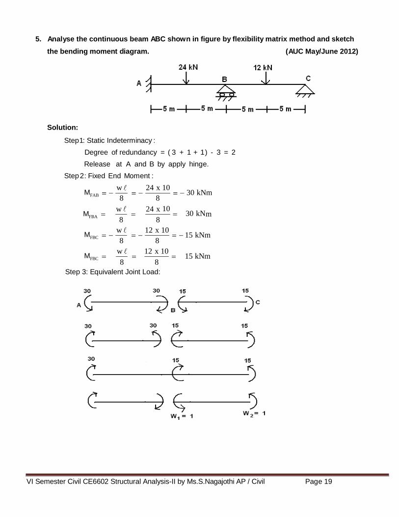
5. Analyse the continuous beam ABC shown in figure by flexibility matrix method and sketch
the bending moment diagram. (AUC May/June 2012)
Solution:
Step1: Static Indeterminacy :
Degree of redundancy = ( 3 + 1 + 1 ) - 3 = 2
Release at A and B by apply hinge.
Step 2: Fixed End Moment :
MFAB 8 8
10 MFBA m
8 8
MFBC 8 8
MFBC
8 8
Step 3: Equivalent Joint Load:

VI Semester Civil CE6602 Structural Analysis-II by Ms.S.Nagajothi AP / Civil Page 20
1 0 2 0
1 2
0 0
1
L
0 0 2
1 2 0 0
1 1.67
1.67 3.33 0 0
3.33 0 0
1.67 0 0 3.33
1.67 0 0 3.33
1
0 0 1 0
0 0 0 and B
X 1 0 0 1
0 1 0 0
1
0 0 1 0
0 0 0
1 0 0 1
0 1 0 0
1.67 3.33 0 0 1 0
1.67 3.33 0 0 0 1 1 0 0 0
1.67
1
0 1 1 0 0 0 3.33 0 1
1.67 0 0 3.33 0 0
1 1.67 0 3.33 0 0 1
0 0 3.33 1.67 0 1
1 0
0 0
3.33 1.67 1
1.67 6.66
1 E
0.086 0.3435 I
0.086 0.1717
efficient
BW
BX
BT
F B x
Step 4: Flexibility co matrix ( B ) :
B
BW
B
Step 5: Flexibility matrix (F) :
F 6 EI
F EI
FX x
EI
EI
Fx
EI
Fx

VI Semester Civil CE6602 Structural Analysis-II by Ms.S.Nagajothi AP / Civil Page 21
1.67 3.33 0 0 0 0
1.67
3.33 0 0 0 0 1 0 0 0
1.67
1
0 1 1 0 0 0 3.33 1 0
1.67 0 0 3.33 0 1
0 0
0 0 1.67 0 3.33 0 1
0 0 3.33 1.67 1 0
0 1
0 0 1
3.33 1.67
0.086 0 0 15 0.3435 EI
0.086 0.1717 3.33 1.67 15
1 F F
x W
0.286 0.144 15
0.144 0.286 15
2.13
4.29
2.13
4.29
1
15 0 0 1 0
0 0 0 15 W B
X 1 0 0 1 2.13
0 1 0 0 4.29
2.13
4.29
10.71
15
BT
F B x
FW w
EI
EI
FW
EI
Step 6 : Displacement matrix (X) :
X W
EI
X
Step 7 : Internal forces (P):
P
P

VI Semester Civil CE6602 Structural Analysis-II by Ms.S.Nagajothi AP / Civil Page 22
30 2.13
30 4.29 P
15 10.71
15 15
32.13
25.71
25.71
0
Step 8 : Final Moments (M):
M
M
6. A cantilever of length 15 m is subjected to a single concentrated load of 50 kN at the middle
of the span. Find the deflection at the free end using flexibility matrix method. EI is
uniform throughout. (AUC May/June 2013)
Solution:
Step1: Static Indeterminacy :
Degree of redundancy = 3 - 3 = 0
It is static determinate structures.
Step 2: Deflection at B :
Apply a unit force at given load.

VI Semester Civil CE6602 Structural Analysis-II by Ms.S.Nagajothi AP / Civil Page 23
1 x 7.5 x
375 x
2 x 7.5 7.5
2 EI 3
17578.1
FBA FBC FBC 0
The deflection is calculated by M
. EI
Deflection at a 21
Deflection at B 25
EI
Hint :To find the deflection, we use M
diagram. EI
7. A two span continuous beam ABC is fixed at A and hinged at support B and C. Span AB =
BC = 9m. Set up flexibility influence coefficient matrix assuming vertical reaction at B
and C as redundant. (AUC May/June 2013)
Solution:
Step1: Static Indeterminacy :
Degree of redundancy = ( 3 + 1 + 1 ) - 3 = 2
Release at A and B by apply hinge.
Step 2: Fixed End Moment :
MFAB M M M
Step 3: Equivalent Joint Load:
Case (i):
Case (ii):
VI Semester Civil CE6602 Structural Analysis-II by Ms.S.Nagajothi AP / Civil Page 24
1
0 0 1 0
0 0 0 and B
X 1 0 0 1
0 1 0 0
1 0 0 1 0
0 0 0
1 0 0 1
0 1 0 0
1
0 0 1 0
1 0 0 and B
X 0 0 0 1
0 1 0 0
1 0 0 1 0
1 0 0
0 0 0 1
0 1 0 0
BW
BX
BW
BX
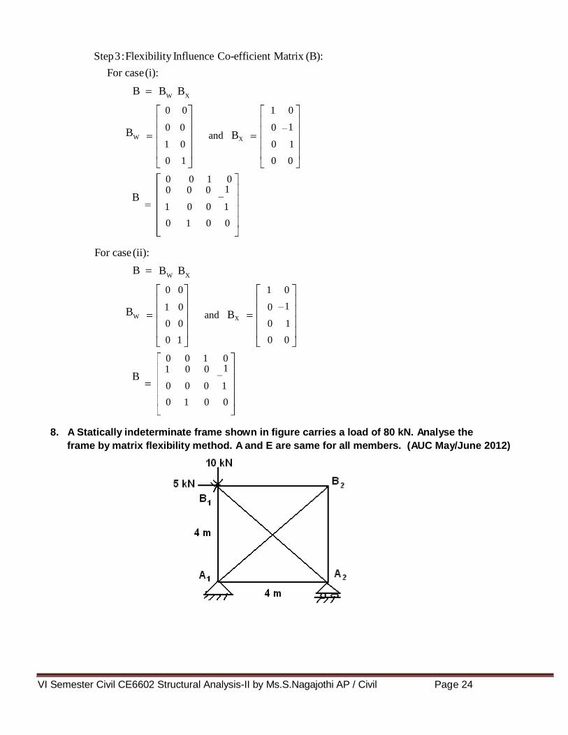
Step 3 : Flexibility Influence Co-efficient Matrix (B):
For case (i):
B
BW
B
For case (ii):
B
BW
B
8. A Statically indeterminate frame shown in figure carries a load of 80 kN. Analyse the
frame by matrix flexibility method. A and E are same for all members. (AUC May/June 2012)

VI Semester Civil CE6602 Structural Analysis-II by Ms.S.Nagajothi AP / Civil Page 25
0 .75
1.333
0 0.75
1
1 0.75
1.25 and B
X
1.25
1.667
0
0 1
BW
BX
Solution:
Step 1: Static Indeterminacy:
Degree of redundancy = Internal Indeterminate – External Indeterminate
= [m – (2j – 3)] – (r – R)
= [6 – (8 – 3)] – (3 - 3)
= 1
Step 2: Member forces:
Take member AD as a redundant.
3 tan =
4
ΣV=0
; sin = 0.6; cos = 0.8;
VA = 1
ΣM = 0
HA = 1.333 and HB = 1.333
At joint D:
FDC = 1 (compression) = -1
At joint C:
ΣV=0
FCA sin = 1
FCA = 1.667; FCB = 1.333
At joint B:
FBA = 0; FBC = 1.333
Analyse by method of joints and find the member forces.
Step 3: Flexibility Co-efficient Matrix:
B
BW

VI Semester Civil CE6602 Structural Analysis-II by Ms.S.Nagajothi AP / Civil Page 26
1.333
0 0.75
1
1 0.75
1.25
1.25
1.667
0
0 1
3 0 0 0 0 0
0 4 0 0 0 0
0 0 3 0 0 0 1
0 0 0 5 0 0
0 0 0 0 5 0
0 0 0 0 0 4
1.25
3 0 0 0 0 0 0.75
0 4 0 0 0 0 1
0 0 3 0 0 0 0.75 0.75 1 0.75 1.25 1.25 1
1.25
0 0 0 5 0 0
0 0 0 0 5 0
0 0 0 0 0 4 1
27
1 AE
7.30
1.333
3 0 0 0 0 0 0
0 4 0 0 0 0
1 0 0 3 0 0 0 0.75 1 0.75 1.25 1.25 1
0 0 0 5 0 0 1.667
0 0 0 0 5 0 0
0 0 0 0 0 4 0
BT
F B x
BT
F B x
B
Step 4: Flexibility matrix (F) :
F AE
FX x
Fx
AE
Fx
27
FW w
FW
AE

VI Semester Civil CE6602 Structural Analysis-II by Ms.S.Nagajothi AP / Civil Page 27
AE 7.30
80
27 AE
1 F F
x W
21.63 k
1.333
0 0.75
1
1 0.75 80 W
1.25 B
X 1.667 21.63
1.25 0
0 1
16.22
84.77
63.78
105.76
27.04
21.63
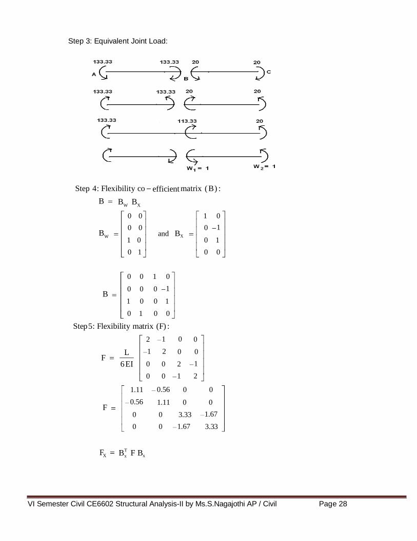
w 16 x 10 133.33 k
2
w 16 x 10 133.33 kNm
2
w 16 x 10 20 kNm
w 16 x 10 20 kNm
Step 5 : Displacement matrix (X) :
X W
X N
Step 6 : Internal forces (P):
P
Final forces, P
9. Analyse the continuous beam shown in figure by flexibility method.
Solution:
Step1: Static Indeterminacy :
Degree of redundancy = ( 3 + 1 + 1 ) - 3 = 2
Release at A and B by apply hinge.
Step 2: Fixed End Moment :
MFAB
MFBA
MFBC
MFCB
2
Nm 12 12
2
12 12
8 8
8 8
VI Semester Civil CE6602 Structural Analysis-II by Ms.S.Nagajothi AP / Civil Page 28
1
0 0 1 0
0 0 0 and B
X 1 0 0 1
0 1 0 0
1 0 2 0
1 2
0 0
1
L
0 0 2
1 2 0 0
1
0 0 1 0
0 0 0
1 0 0 1
0 1 0 0
0.56 1.11 0 0
0.56
1.11 0 0
1.67 0 0 3.33
1.67 0 0 3.33
efficient
BW
BX
BT
F B x
Step 3: Equivalent Joint Load:
Step 4: Flexibility co matrix ( B ) :
B
BW
B
Step 5: Flexibility matrix (F) :
F 6 EI
F
FX x

VI Semester Civil CE6602 Structural Analysis-II by Ms.S.Nagajothi AP / Civil Page 29
1
0.121
0.121 0.962
0.241
0.56 1.11 0 0 1 0
0.56 1.11 0 0 0 1 1 0 0 0
1.67
0 1 1 0 0 0 3.33 0 1
1.67 0 0 3.33 0 0
1
1 0
0 0.56 0 1.11 0
0.56 1.11 3.33 1.67 0 1
0 0
1.11 0.56
0.56 4.44
0.56 1.11 0 0 0 0
0.56
1.11 0 0 0 0 1 0 0 0
1.67
0 1 1 0 0 0 3.33 1 0
1.67 0 0 3.33 0 1
0 0
0 0 0.56 0 1.11 0
0.56 1.11 3.33 1.67 1 0
0 1
0 0
3.33 1.67
1 F F
x W
0.121 0 0 113.33 0.962
0.121 0.241 3.33 1.67 20
41.62
82.90
41.62
82.90
BT
F B x
Fx
Fx
FW w
FW
Step 6 : Displacement matrix (X) :
X W
X

VI Semester Civil CE6602 Structural Analysis-II by Ms.S.Nagajothi AP / Civil Page 30
1 2
113.33 0 0 1 0
0 0 0 0 W B
X 1 0 0 1 41.62
0 1 0 0 82.90
41.62
82.90
30.43
20
133.33 41.62
133.33 82.90 P
20 30.43
20 20
174.95
50.43
50.43
0
w 4 x 3 3 kNm
2
4 x 3 3 kNm
2
Step 7 : Internal forces (P):
P
P
Step 8 : Final Moments (M):
M
M
10. Analyse the continuous beam shown in figure by flexibility method.
Solution:
Step1: Static Indeterminacy :
Degree of redundancy = ( 1 + 1 + 1 + 1) - 2 = 2
Release at B and C by apply hinge.
Step 2: Fixed End Moment :
2
MFAB 12 12
w 2
MFBA 12 12
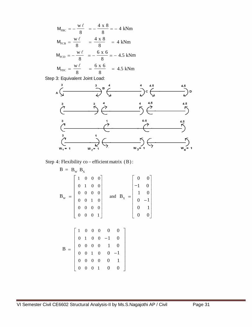
VI Semester Civil CE6602 Structural Analysis-II by Ms.S.Nagajothi AP / Civil Page 31
w 4 x 8 4 kNm
w 4 x 8 4 kNm
w 6 x 6 4.5 kN
w 6 x 6 4.5 kNm
1 0 0 0 0 0
0 1 0 0 1 0
0 0 0 0 1 0 and B
X 1 0 0 1 0 0
0 0 0 0 0 1
0 0 0 1 0 0
1 0 0 0 0 0
0 1 0 0 1 0
0 0 0 0 1 0
1 0 0 1 0 0
0 0 0 0 0 1
0 0 0 1 0 0
efficient
BW
BX
MFBC
8 8
MFCB 8 8
MFCD 8 8
m
MFDC
8 8
Step 3: Equivalent Joint Load:
Step 4: Flexibility co matrix ( B ) :
B
BW
B
VI Semester Civil CE6602 Structural Analysis-II by Ms.S.Nagajothi AP / Civil Page 32
1 0 2 0 0 0
1 2
0 0 0 0
1 0 0 0 2 0 L
1 2
1
0 0 0 0
0 0 0 0 2
1 2 0 0 0 0
0.5 0 1 0 0 0
0.5 1
0 0 0 0
0.67 0 0 0 1.33 0 1
0.67
0.5
0 0 1.33 0 0
0 0 0 0 1
0.5 0 0 0 0 1
0.5 0 1 0 0 0 0 0
0.5 1
0 0 0 0 1 0
0.67 0 0 0 1.33 0 1 0 1 1 0 0 0 0 1
0.67
0 0 0 1 1 0 0 0 1.33 0 0 0 1
0.5 0 0 0 0 1 0 1
0.5 0 0 0 0 1 0 0
0 0
1 0
1 0 1 1.33 0.67 0 0.5 0 1
0 0 0.67 1.33 1 0.5 0 1
0 1
0 0
2.33 0.67 1
0.67 2.33
1 E
0.135 0.468 I
0.135 0.468
BT
F B x
Step 5: Flexibility matrix (F) :
F 6 EI
F EI
FX x
EI
EI
Fx
EI
Fx

VI Semester Civil CE6602 Structural Analysis-II by Ms.S.Nagajothi AP / Civil Page 33
0.5 0 1 0 0 0 1 0 0 0
0.5 1
0 0 0 0 0 1 0 0
0.67 0 0 0 1.33 0 0 0 0 0 1 1 0 0 0 0 1
0.67
0 0 0 1 1 0 0 0
0.5
1.33 0 0 0 0 1 0
0 0 0 0 1 0 0 0 0
0.5 0 0 0 0 1 0 0 0 1
1 0 0 0
0 1 0 0
0 0 0 0 1 1.33 0.67 0 0.5 0 1
0 0 0.67 1.33 1 0.5 0 0 1 0
0 0 0 0
0 0 0 1
1 0.67 0.5 0 1
0 0 1.33 0.5
3
1 0.135 0.5 1 0.67 0 0.468 EI
0.135 0.468 0 0 1.33 0.5 0.5
4.5
1 F F
x W
3
1 0.468 0.134 0 0.234 .068
0.068 0.135 0.599 0.234 0.5
4.5
0.139
0.685
0.139
0.685
BT
F B x
FW w
EI
EI
FW
EI
Step 6 : Displacement matrix (X) :
X W
EI
X

VI Semester Civil CE6602 Structural Analysis-II by Ms.S.Nagajothi AP / Civil Page 34
1 0 0 0 0 0 3 3
0 1 0 0 1 0 1 0.861
0 0 0 0 1 0 0.5 0.139 W B
X 0 1 4.5 0 1 0 0 1.185
0 0 0 0 0 1 0.139 0.685
0.685 4.5 0 0 0 1 0 0
3 3
3 0.861
4 0.139 P
4 1.185
4.5 0.685
4.5 4.5
0
3.861
3.861
5.185
5.185
0
Step 7 : Internal forces (P):
P
Step 8 : Final Moments (M):
M
M
Related Documents


![[T] The effect of Pilates method on elderly flexibility · Guimarães ACA, de Azevedo SF, ... Pilates method presented a lower flexibility degree, ... exercises for each session,](https://static.cupdf.com/doc/110x72/5b14e1447f8b9a54488ca053/t-the-effect-of-pilates-method-on-elderly-guimaraes-aca-de-azevedo-sf-.jpg)