Part Number: 7179M1200-1.0.0 Rev: B Released: 2017-12 Unison Foundry ™ Mini Panel Installation and User Operation Manual Version 1.0.0

Welcome message from author
This document is posted to help you gain knowledge. Please leave a comment to let me know what you think about it! Share it to your friends and learn new things together.
Transcript

Part Number: 7179M1200-1.0.0 Rev: B
Released: 2017-12
Unison Foundry™
Mini Panel
Installation andUser Operation Manual
Version 1.0.0

ETC®, Un ison®, and Unison Foundry ™ are e i ther reg is tered t rademarks or t rademarks of E lect ron ic
Theatre Contro l s , Inc . in the Un i ted States and other countr ies .
A l l other t rademarks , both marked and not marked, are the property of the i r respect ive owners .
ETC intends th i s document , whether pr inted or e lect ron ic , to be prov ided in i t s ent i re ty . Th i s
product i s intended for profess iona l use on ly . Read th i s ent i re document before us ing th i s product .

Table of Contents i
Table of Contents
Introduction . . . . . . . . . . . . . . . . . . . . . . . . .1
Features and Specification . . . . . . . . . . . . . . . . . . . . . . .2
Codes and Standards . . . . . . . . . . . . . . . . . . . . . . . . . . .2
Important Safeguards . . . . . . . . . . . . . . . . . . . . . . . . . .2
Warnings and Notice Conventions . . . . . . . . . . . . . . . .2
Help from ETC Technical Services . . . . . . . . . . . . . . . . .3Contact ETC. . . . . . . . . . . . . . . . . . . . . . . . . . . . . . . . . . . . . . . . .3
Chapter 1 Prepare for Installation . . . . . . . . . . . . . . . .4
Inspect the Shipment . . . . . . . . . . . . . . . . . . . . . . . . . . .4
Main Circuit Breaker Protection . . . . . . . . . . . . . . . . . .4
Installation Environment . . . . . . . . . . . . . . . . . . . . . . . .4
Tools and Supplies . . . . . . . . . . . . . . . . . . . . . . . . . . . . .5
Conduit Access . . . . . . . . . . . . . . . . . . . . . . . . . . . . . . . .5
Electrical Input Wiring Requirements . . . . . . . . . . . . . .6
Control Wiring Requirements . . . . . . . . . . . . . . . . . . . .7
Chapter 2 Installation . . . . . . . . . . . . . . . . . . . . . . . . . .8
Mount the Controller . . . . . . . . . . . . . . . . . . . . . . . . . . .8
Rough-In and Terminate Cable . . . . . . . . . . . . . . . . . . .9High Voltage Wiring . . . . . . . . . . . . . . . . . . . . . . . . . . . . . . . . .9Low Voltage Wiring . . . . . . . . . . . . . . . . . . . . . . . . . . . . . . . . .13
Configure the Mini Panel. . . . . . . . . . . . . . . . . . . . . . .16Set the Emergency UL 924 Configuration Switch. . . . . . . . . .16Set the Emergency UL 924 Load Shed Switch . . . . . . . . . . . . .16Set the Emergency UL 924 Inclusion Switches . . . . . . . . . . . .17Set the Demand Response Levels . . . . . . . . . . . . . . . . . . . . . .17Set the Data Loss Behavior. . . . . . . . . . . . . . . . . . . . . . . . . . . .17Update the Software . . . . . . . . . . . . . . . . . . . . . . . . . . . . . . . .17Restore Defaults . . . . . . . . . . . . . . . . . . . . . . . . . . . . . . . . . . . .17

ii Unison Foundry Mini Panel Installation and User Operation Manual
Chapter 3 Power Up and Set DMX Address . . . . . . .18
Before Applying Power to the Mini Panel . . . . . . . . .18
Power Up. . . . . . . . . . . . . . . . . . . . . . . . . . . . . . . . . . . .18
Set the DMX Address . . . . . . . . . . . . . . . . . . . . . . . . . .19Manually Set the DMX Address . . . . . . . . . . . . . . . . . . . . . . . .19
Check Features . . . . . . . . . . . . . . . . . . . . . . . . . . . . . . .22
Demand Response . . . . . . . . . . . . . . . . . . . . . . . . . . . .22
Appendix A RDM Parameters . . . . . . . . . . . . . . . . . . . .23
Introduction 1
Introduction
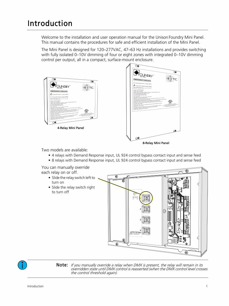
Welcome to the installation and user operation manual for the Unison Foundry Mini Panel. This manual contains the procedures for safe and efficient installation of the Mini Panel.
The Mini Panel is designed for 120–277VAC, 47–63 Hz installations and provides switching with fully isolated 0–10V dimming of four or eight zones with integrated 0–10V dimming control per output, all in a compact, surface-mount enclosure.
Two models are available:
• 4 relays with Demand Response input, UL 924 control bypass contact input and sense feed
• 8 relays with Demand Response input, UL 924 control bypass contact input and sense feed
You can manually override each relay on or off.
• Slide the relay switch left to
turn on
• Slide the relay switch right
to turn off
Note: If you manually override a relay when DMX is present, the relay will remain in its overridden state until DMX control is reasserted (when the DMX control level crosses the control threshold again).
4-Relay Mini Panel
8-Relay Mini Panel

2 Unison Foundry Mini Panel Installation and User Operation Manual
Features and Specification
Mini Panels are designed for indoor use only!
The Mini Panel features:
• Either four or eight mechanically latching relays. Relays are rated for the following load types:
- 100,000 cycles of 20A resistive load
- 30,000 cycles of 20A tungsten load at 277 VAC
- 30,000 cycles of standard ballast at 20A, 120 or 277 VAC
- 30,000 cycles of electronic ballast at 16A, 120 or 277 VAC
• Either four or eight 0–10V outputs with current sink of 100 mA
• Dry contact closures for UL 924 control bypass and Demand Response control input
• Integrated sense feed for UL 924 control bypass
Codes and Standards
The Mini Panel meets or exceeds the following regulatory standards:
• UL 916 for energy management equipment
• UL 924 for emergency lighting and power equipment
• UL 2043 for installation in air-handling (plenum) spaces
Important Safeguards
READ AND FOLLOW ALL SAFETY INSTRUCTIONS.
When using electrical equipment, basic safety precautions should always be followed including the following:
• Do not use outdoors.
• Do not mount near gas or electric heaters.
• Equipment should be mounted in locations and at heights where it will not readily be subjected
to tampering by unauthorized personnel.
• The use of accessory equipment not recommended by the manufacturer may cause an unsafe
condition.
• Do not use this equipment for anything other than its intended use.
• Operation and servicing by qualified personnel only!
SAVE THESE INSTRUCTIONS
Warnings and Notice Conventions
These symbols are used in this document to alert you to danger or important information.
Note: Notes are helpful hints and information that is supplemental to the main text.
CAUTION: A Caution statement indicates situations where there may be undefined or unwanted consequences of an action, potential for data loss or an equipment problem.
WARNING: A Warning statement indicates situations where damage may occur, people may be harmed, or there are serious or dangerous consequences of an action.
WARNING: RISK OF ELECTRIC SHOCK! This warning statement indicates situations where there is a risk of electric shock.

Introduction 3
Help from ETC Technical Services
If you are having difficulties, your most convenient resources are the references given in this manual. To search more widely, try the ETC Web site at etcconnect.com. If none of these resources is sufficient, contact ETC Technical Services directly at one of the offices identified below. Emergency service is available from all ETC offices outside of normal business hours.
When calling for help, please have the following information handy:
• Product model and serial number (located on the product label)
• List of connected load types
• Connected devices, if any
Contact ETC
Please email comments about this manual to: [email protected].
Americas United KingdomETC, Inc. ETC Ltd
Technical Services Department Technical Services Department
3031 Pleasant View Road 26-28 Victoria Industrial Estate
Middleton, WI 53562 Victoria Road,
800-775-4382 (USA, toll-free) London W3 6UU England
+1-608 831-4116 +44 (0)20 8896 1000
[email protected] [email protected]
Asia GermanyETC Asia ETC GmbH
Technical Services Department Technical Services Department
Room 1801, 18/F Ohmstrasse 3
Tower 1, Phase 1 Enterprise Square 83607 Holzkirchen, Germany
9 Sheung Yuet Road +49 (80 24) 47 00-0
Kowloon Bay, Kowloon, Hong Kong [email protected]
+852 2799 1220

4 Unison Foundry Mini Panel Installation and User Operation Manual
Chapter 1Prepare for Installation
Inspect the ShipmentBefore you begin installation, check your shipment and confirm that it arrived complete and
undamaged.
1: Check the shipping box for physical damage.
• If you find damage, document it to help with a claim against your shipper.
2: Inspect the order for completeness.
• Check the box contents received against the packing list to ensure that your order received is
complete.
• If you discover a problem with the contents of the shipment, contact ETC Technical Services
at the location nearest you. See Help from ETC Technical Services on page 3.
Main Circuit Breaker ProtectionBefore beginning installation of your Mini Panel, make sure you have installed a main circuit breaker
cabinet or other readily accessible input power disconnect device.
When more than one power source is supplying the Mini Panel, a voltage separator may be required by
local code. This voltage divider is an accessory option, sold separately, and available for use when local
code requires. Order ETC part number 7187A4021.
Installation EnvironmentFollow these guidelines for the installation environment:
• Intended for surface wall mounting. The installation location and the mounting hardware must
support at least 20 lb (9 kg).
• Install the enclosure in a location where it will not be subject to tampering or vandalism.
• For indoor use only! Operates at ambient temperature between 0°C–40°C (32°F–104°F), dry
room 5–90% non-condensing relative humidity.
• The Mini Panel is rated for installation in a plenum space.
WARNING: Mini Panel circuits installed without an accessible power disconnect device cannot be serviced or operated safely.
Note: Always follow applicable building and local electrical code requirements when installing this equipment.
Prepare for Installation 5
Tools and SuppliesThe following tools and supplies are required for installation but are not included with the Mini Panel.
• Mounting hardware: four mounting bolts or screws
• Set of screwdrivers, including both flat-blade and Phillips-head types
• Conduit and supporting hardware
• Insulation stripping tool
• Appropriately sized wire nuts or WAGO® installation connectors
• Small 4–6” (10–15 cm) cable ties
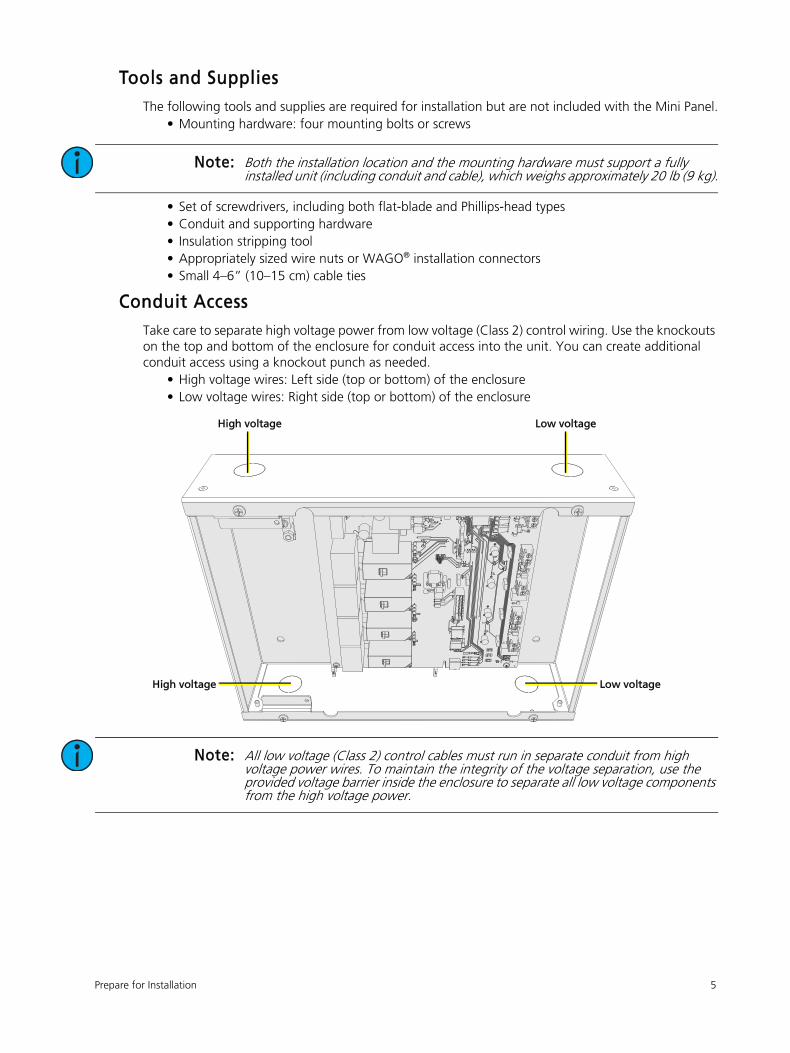
Conduit AccessTake care to separate high voltage power from low voltage (Class 2) control wiring. Use the knockouts
on the top and bottom of the enclosure for conduit access into the unit. You can create additional
conduit access using a knockout punch as needed.
• High voltage wires: Left side (top or bottom) of the enclosure
• Low voltage wires: Right side (top or bottom) of the enclosure
Note: Both the installation location and the mounting hardware must support a fully installed unit (including conduit and cable), which weighs approximately 20 lb (9 kg).
Note: All low voltage (Class 2) control cables must run in separate conduit from high voltage power wires. To maintain the integrity of the voltage separation, use the provided voltage barrier inside the enclosure to separate all low voltage components from the high voltage power.
High voltage Low voltage
Low voltageHigh voltage

6 Unison Foundry Mini Panel Installation and User Operation Manual
Electrical Input Wiring RequirementsRemove the main cover and the high voltage cover to access the high voltage electrical terminations,
including control power input and relay inputs/outputs, which are located on the left side of the
enclosure.
Note: Always follow applicable US National Electrical Code (NEC) and local electrical code requirements when installing and powering this equipment.
CAUTION: For your own safety, do not supply power to the enclosure until all installation is complete, connected circuits have been tested and found free of electrical shorts, and covers have been replaced. Follow appropriate Lockout/Tagout procedures as described in National Fire Protection Association (NFPA) Standard 70E.
Electrical Terminations
PurposeTerminal Accepts
Type Notes
Power Input12–20 AWG
(4–0.5 mm2)
Supports a 20A input
breaker (maximum)20A maximum, 120–277 VAC, 47–63 Hz
UL 924
Emergency Sense
Feed Input
12–20 AWG
(4–0.5 mm2)
Optional sense feed
with a 20A maximum
input breaker
Upon loss of sense feed power, activates
Mini Panel emergency state, driving
configured loads On, and others Off.
Relay Output6–20 AWG
(16–0.5 mm2)
Each relay supports a
maximum current of
20A in discrete feed
configuration
Each relay in the enclosure can be
discretely fed, and configured for bridging
from the input power connection or
bridging between the relays.
Note: When bridging input power (hot) across relays in the enclosure, the total loading of all bridged relays is limited to 20A.
IN1
THRU1
OUT1
IN2
THRU2
OUT2
IN3
THRU3
OUT3
IN4
THRU4
OUT4
LSENSE
N
Control power andoptional sense feed input
Output terminal blocks(4 or 8, depending on
the model)
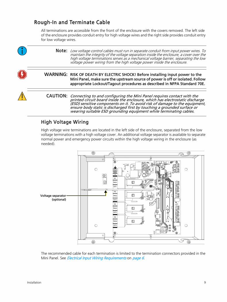
Voltage separator(optional)

Prepare for Installation 7
Control Wiring RequirementsAll control wires are terminated to the low voltage (right) side of the enclosure, accessible with the
main cover removed.
Control Terminations
PurposeTerminals
AcceptType Notes
UL 924
Emergency
Contact Input
16–22 AWG
(1.5–0.5 mm2)
Dry: Normally Open
(default) or Normally
Closed Closure
Activates Mini Panel emergency state,
driving configured loads On, and others
Off. See About Contact Inputs on
page 14.
Demand
Response
Contact Input
Dry: Maintained Closure
Limits the maximum level of each output
to the configured level set at the
configuration potentiometers. See About Contact Inputs on page 14.
0–10V OutputsCapable of sinking
100 mA of current
Allows for 0–10V dimming control of
connected compatible loads. See
Terminate 0–10V Outputs on page 15.
Demand Response Contact
UL 924 Emergency Contact
0–10V out 100 mA(one per channel)
8 Unison Foundry Mini Panel Installation and User Operation Manual
Chapter 2Installation
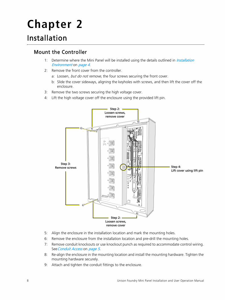
Mount the Controller1: Determine where the Mini Panel will be installed using the details outlined in Installation
Environment on page 4.
2: Remove the front cover from the controller.
a: Loosen, but do not remove, the four screws securing the front cover.
b: Slide the cover sideways, aligning the keyholes with screws, and then lift the cover off the
enclosure.
3: Remove the two screws securing the high voltage cover.
4: Lift the high voltage cover off the enclosure using the provided lift pin.
5: Align the enclosure in the installation location and mark the mounting holes.
6: Remove the enclosure from the installation location and pre-drill the mounting holes.
7: Remove conduit knockouts or use knockout punch as required to accommodate control wiring.
SeeConduit Access on page 5.
8: Re-align the enclosure in the mounting location and install the mounting hardware. Tighten the
mounting hardware securely.
9: Attach and tighten the conduit fittings to the enclosure.
Step 4: Lift cover using lift pin
Step 3: Remove screws
Step 2: Loosen screws, remove cover
Step 2: Loosen screws, remove cover
Installation 9
Rough-In and Terminate CableAll terminations are accessible from the front of the enclosure with the covers removed. The left side
of the enclosure provides conduit entry for high voltage wires and the right side provides conduit entry
for low voltage wires.
High Voltage Wiring
High voltage wire terminations are located in the left side of the enclosure, separated from the low
voltage terminations with a high voltage cover. An additional voltage separator is available to separate
normal power and emergency power circuits within the high voltage wiring in the enclosure (as
needed).
The recommended cable for each termination is limited to the termination connectors provided in the
Mini Panel. See Electrical Input Wiring Requirements on page 6.
Note: Low voltage control cables must run in separate conduit from input power wires. To maintain the integrity of the voltage separation inside the enclosure, a cover over the high voltage terminations serves as a mechanical voltage barrier, separating the low voltage power wiring from the high voltage power inside the enclosure.
WARNING: RISK OF DEATH BY ELECTRIC SHOCK! Before installing input power to the Mini Panel, make sure the upstream source of power is off or isolated. Follow appropriate Lockout/Tagout procedures as described in NFPA Standard 70E.
CAUTION: Connecting to and configuring the Mini Panel requires contact with the printed circuit board inside the enclosure, which has electrostatic discharge (ESD) sensitive components on it. To avoid risk of damage to the equipment, ensure body static is discharged first by touching a grounded surface or wearing suitable ESD grounding equipment while terminating cables.
IN1
THRU1
OUT1
IN2
THRU2
OUT2
IN3
THRU3
OUT3
IN4
THRU4
OUT4
LSENSE
N
Voltage separator(optional)

10 Unison Foundry Mini Panel Installation and User Operation Manual
Sample Power Input and Relay Output Terminations
The following are sample termination scenarios for Mini Panel installations. Use these scenarios only as
a reference, and refer to your electrical and wiring plans for your specific installation requirements.
Note: The In and Thru terminals are electrically connected on the circuit board.
Note: If any emergency circuits are fed or controlled from this panel, the panel must be located electrically where fed from a UPS, generator, or other guaranteed source of power during emergency and power outage situations.
Note: Voltage barriers between normal circuits with different voltage inputs are only required if the wiring used for 120V circuits is not rated for 277V.
IN1
THRU1
OUT1
IN2
THRU2
OUT2
IN3
THRU3
OUT3
IN4
THRU4
OUT4
L
SENSE
N
To load
From 120V normal/emergency breaker
To load
From 120V normal breaker
To load
From 277V normal breaker
To load
Ground
Neutral
Voltage separator
Voltage separator
From 120V normal breaker
Bridging Relays with
Normal/Emergency Power and
Discrete Fed Breakers
In this installation scenario, a single
Normal/Emergency input power
connection (line, neutral, and
ground) is bridged between the
control input and one or more relay
inputs. Additional relays can be
discretely fed from circuit breakers.
Because the input power is
Normal/Emergency, a Normal
sense feed has been added to drive
the Mini Panel to its emergency
control configuration on loss of
normal power. This circuit does not
feed a load from the Mini Panel.
Voltage separators are available
and sold separately for separating
between mixed voltage or normal
and emergency loads.
When bridging the input power,
the total load is limited to 20A
across all connected relays.
Installation 11
IN1
THRU1
OUT1
IN2
THRU2
OUT2
IN3
THRU3
OUT3
IN4
THRU4
OUT4
L
SENSE
N
To load
To load
To load
To load
Ground
Neutral
From breaker
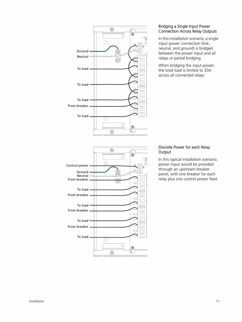
Bridging a Single Input Power
Connection Across Relay Outputs
In this installation scenario, a single
input power connection (line,
neutral, and ground) is bridged
between the power input and all
relays or partial bridging.
When bridging the input power,
the total load is limited to 20A
across all connected relays.
IN1
THRU1
OUT1
IN2
THRU2
OUT2
IN3
THRU3
OUT3
IN4
THRU4
OUT4
L
SENSE
N
To load
To load
To load
To load
GroundNeutral
From breaker
From breaker
From breaker
From breaker
Control power
Discrete Power for each Relay
Output
In this typical installation scenario,
power input would be provided
through an upstream breaker
panel, with one breaker for each
relay plus one control power feed.

12 Unison Foundry Mini Panel Installation and User Operation Manual
Terminate Input Power and Relay Outputs
1: Terminate input power:
a: Pull input power (2 wires plus ground) to the left side of the enclosure.
b: Strip 1/2” (12 mm) of insulation from each wire.
c: Insert the ground wire into the ground terminal (labeled with a ground symbol), and torque
the terminal to 1.3 foot-pounds (1.76 N·m).
d: Insert the line (hot) wire into the L terminal and torque the terminal to 1.3 foot-pounds
(1.76 N·m).
e: Insert the optional sense feed wire into the SENSE terminal and torque the terminal to
1.3 foot-pounds (1.76 N·m).
f: Insert the neutral wire into the N terminal and torque the terminal to 1.3 foot-pounds
(1.76 N·m).
2: Terminate relay outputs (4 or 8 relays):
a: Pull relay output wires (2 to 3 wires for each relay, depending on the installation
requirements) to the left side of the enclosure.
b: Strip 1/2” (12 mm) of insulation from each wire.
c: Insert the line (hot) wire into the terminal marked IN* (IN2, IN3, etc.) and torque the terminal
to 1.3 foot-pounds (1.76 N·m).
d: When bridging relay outputs, insert a wire between the THRU* terminal and the next relay
IN* terminal. If you are not bridging outputs, do not terminate to the THRU terminal.
e: Connect the load wire to the terminal marked OUT* (OUT2, OUT3, etc.) and torque the
terminal to 1.3 foot-pounds (1.76 N·m).
3: Install a relay voltage separator between any normal power relays and emergency power relays
in the enclosure, or between relays with different voltage inputs. Additional relay voltage
separators are available for purchase from ETC. Order part number 7187A4021.
IN1
THRU1
OUT1
IN2
THRU2
OUT2
IN3
THRU3
OUT3
IN4
THRU4
OUT4
LSENSE
N
Voltage separator

Installation 13
Low Voltage Wiring
Low voltage wire terminations are located on the right side of the enclosure, visible with the front
cover removed.
Demand Response Contact
UL 924 Emergency Contact
0–10V out 100 mA(one per channel)

14 Unison Foundry Mini Panel Installation and User Operation Manual
About Contact Inputs
Contact inputs are available for:
• Demand Response Input: Accepts a remote trigger that allows the controller to reduce lighting
levels, thereby reducing power consumption.
• UL 924 Emergency Contact Input: Triggers emergency lighting control bypass from a system such
as a fire alarm.
The contact inputs can be configured as follows:
• Demand Response input requires a normally open dry contact closure.
• UL 924 Emergency Contact input is configurable to be a normally open or normally closed
contact, and requires a maintained dry contact closure.
A configuration switch is available for the UL 924 Emergency Contact to further define normally closed
(maintained) configuration as needed. Demand Response contacts are always open and are not
provided with additional configuration options.
Terminate Contact Inputs
Dry contact input terminations are the same regardless of function.
1: Pull 2 wires to the right side of the enclosure.
2: Strip 1/4” (6 mm) of insulation from each wire.
3: Insert one wire into each terminal for the contact input, and torque the terminal to
4.4 inch-pounds (0.5 N·m).
EMER
GENC
Y D
MND
RES
P
_+
MODE SET RESET
NO O
FF N
C Demand Response Input
UL 924 Emergency Contact Input
UL 924 Emergency ContactConfiguration Switch

Installation 15
Terminate 0–10V Outputs
The Mini Panel offers fully isolated 0–10V output
control for each zone, allowing direct connection
to dimming ballasts and LED drivers. The 0–10V
outputs are capable of sinking a current of up to
100 mA.
1: Pull 0–10V wiring (typically a gray and violet
wire pair) to the right side of the enclosure.
2: Strip 1/4” (6 mm) of insulation from each
wire.
3: Insert the positive wire (typically gray) into
the terminal labeled “+” and torque the
terminal to 4.4 inch-pounds (0.5 N·m).
4: Insert the negative wire (typically violet) into
the terminal labeled “-” and torque the
terminal to 4.4 inch-pounds (0.5 N·m).
About DMX Control Wiring
The Mini Panel connects to a DMX512-A source (provided by others) for control.
DMX wiring runs can be daisy chains of up to 32 devices with no Y’s or loops. Each DMX daisy chain
must be terminated for proper control performance (see Terminate the Final DMX Device on page 16).
ETC recommends using Belden 9729 (or approved equivalent) Class 2 wire. Belden 1583A or
equivalent Cat5, Cat5e, or Cat 6 UTP wire is also acceptable when properly shielded or installed in
grounded metal conduit and connected using the Cat5 IDC termination kit (ETC part number
4100A1013). This termination kit is not provided with the Mini Panel. Contact ETC to purchase
termination kits if required.
The total combined length of a DMX wire run (using Belden 9729 or equivalent) may not exceed
1,000 ft (305 m).
WARNING: RISK OF DEATH OR INJURY BY ELECTRIC SHOCK! 0–10V wiring may not be fully isolated from high voltage AC power. Do not assume that 0–10V wiring is safe to touch, even when run as an NEC Class 2 signal. Test for AC voltage to ground before terminating any 0–10V control wiring to the Mini Panel.
CAUTION: Only ballasts and drivers with isolating transformers are recommended for use with the Mini Panel.
Note: All control wiring should be installed and terminated by a qualified installer and should follow standard wiring installation practices.
For more information on DMX control wiring requirements, see these and other support articles at etcconnect.com:
• etcconnect.com/Support/Articles/DMX-512-Info.aspx• etcconnect.com/Support/Articles/DMX-Over-Cat5.aspx
EMER
GENC
Y D
MND
RES
P
_+
MODE SET RESET
NO O
FF N
C
CH1
0–10
V
_+
CH2
0–10
V
_+
CH3
0–10
V
_+
CH4
0–10
V
0 100
DMND RESP LEVEL
IN EM
ERG
0 100
DMND RESP LEVEL
IN EM
ERG
0 100
DMND RESP LEVEL
IN EM
ERG
0 100
DMND RESP LEVEL
IN EM
ERG
SHIELD–+SHIELD–+
THRU
IN
DMX TERMOFFON
J8 DMX
SIGNAL
ERRORPOWER
DMND RESP
EMERG
DMX 0–10V
Outputs

16 Unison Foundry Mini Panel Installation and User Operation Manual
Terminate DMX
1: Pull DMX wiring to the right side of the
enclosure.
2: Terminate the DMX cable to the DMX
header by following the steps in the
termination kit supplied with the unit.
3: Insert the DMX header into the DMX
connection on the Mini Panel.
Terminate the Final DMX Device
You must terminate the final device (and only the
final device) in each DMX daisy chain for proper
control performance. To terminate the final device
in a chain, set the DMX termination switch to ON
(see image at right).
Configure the Mini Panel
Set the Emergency UL 924 Configuration Switch
To configure the UL 924 contact input, set
the Emergency UL 924 Configuration
switch to one of the following options:
• NO (normally open [default])
• NC (normally closed)
• Off (disabled).
Set the Emergency UL 924 Load Shed Switch
The Emergency UL 924 Load Shed switch provides configuration to enable or disable load shedding
when an Emergency Contact input is activated (opened or closed depending on the state of the
Emergency UL 924 Configuration switch). By factory default, this switch is set to On (enabled).
Load shedding functions in conjunction with the Emergency UL 924 Inclusion switch for each output
(see Set the Emergency UL 924 Inclusion Switches on page 17). The table below describes what occurs
when the Emergency Contact input is activated.
UL 924 Load Shedding
Load Shed Switch State
Output Included in Emergency?
Result
On YesRelay will close and the 0–10V output will be driven to its
maximum output level.
On No Load and its connected 0–10V output will be turned off.
Off YesRelay will close and the 0–10V output will be driven to its
maximum output level.
Off No Load remains at its current level.
_+
CH2
0–10
V
_+
CH3
0–10
V
_+
CH4
0–10
V
IN EM
ERG
IN EM
ERG
IN EM
ERG
SHIELD–+SHIELD–+
THRU
IN
DMX TERMOFFON
J8 DMX
SIGNAL
ERRORPOWER
DMND RESP
EMERG
0 100
DMND RESP LEVEL
0 100
DMND RESP LEVEL
0 100
DMND RESP LEVEL
DMX
DMXConnection
DMXTermination
Switch
EMER
GENC
Y D
MND
RES
P
MODE SET RESET
NO O
FF N
CLO
AD
SHED
SENS
EEN
ABLE
UL 924Configuration
Switch
UL 924 LoadShed Switch
Installation 17
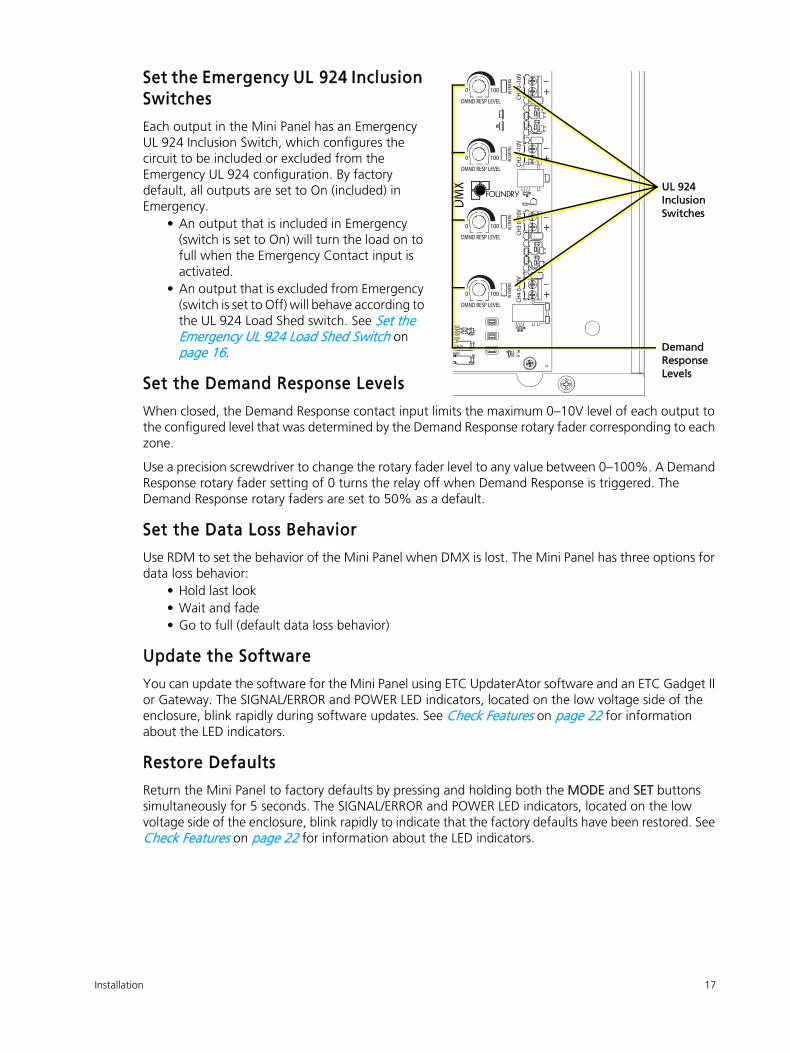
Set the Emergency UL 924 Inclusion Switches
Each output in the Mini Panel has an Emergency
UL 924 Inclusion Switch, which configures the
circuit to be included or excluded from the
Emergency UL 924 configuration. By factory
default, all outputs are set to On (included) in
Emergency.
• An output that is included in Emergency
(switch is set to On) will turn the load on to
full when the Emergency Contact input is
activated.
• An output that is excluded from Emergency
(switch is set to Off) will behave according to
the UL 924 Load Shed switch. See Set the Emergency UL 924 Load Shed Switch on
page 16.
Set the Demand Response Levels
When closed, the Demand Response contact input limits the maximum 0–10V level of each output to
the configured level that was determined by the Demand Response rotary fader corresponding to each
zone.
Use a precision screwdriver to change the rotary fader level to any value between 0–100%. A Demand
Response rotary fader setting of 0 turns the relay off when Demand Response is triggered. The
Demand Response rotary faders are set to 50% as a default.
Set the Data Loss Behavior
Use RDM to set the behavior of the Mini Panel when DMX is lost. The Mini Panel has three options for
data loss behavior:
• Hold last look
• Wait and fade
• Go to full (default data loss behavior)
Update the Software
You can update the software for the Mini Panel using ETC UpdaterAtor software and an ETC Gadget II
or Gateway. The SIGNAL/ERROR and POWER LED indicators, located on the low voltage side of the
enclosure, blink rapidly during software updates. See Check Features on page 22 for information
about the LED indicators.
Restore Defaults
Return the Mini Panel to factory defaults by pressing and holding both the MODE and SET buttons
simultaneously for 5 seconds. The SIGNAL/ERROR and POWER LED indicators, located on the low
voltage side of the enclosure, blink rapidly to indicate that the factory defaults have been restored. See
Check Features on page 22 for information about the LED indicators.
_+
CH1
0–10
V
_+
CH2
0–10
V
_+
CH3
0–10
V
_+
CH4
0–10
V
IN EM
ERG
IN EM
ERG
IN EM
ERG
IN EM
ERG
GNAL
RROROWER
D RESP
MERG
0 100
DMND RESP LEVEL
0 100
DMND RESP LEVEL
0 100
DMND RESP LEVEL
0 100
DMND RESP LEVEL
DMX UL 924
Inclusion Switches
Demand Response Levels

18 Unison Foundry Mini Panel Installation and User Operation Manual
Chapter 3Power Up and Set DMX Address
Before Applying Power to the Mini Panel
1: Clean out dust, metal scraps,
or other debris from the
enclosure.
2: Check for loose connections,
bare wires, or damaged
insulation on both the low
voltage and high voltage sides
of the enclosure.
3: Replace the high voltage cover
on the unit and secure with
screws.
4: Check that all configuration
switches are set according to
the installation requirement.
See Configure the Mini Panel on page 16.
Power UpApply power at the breaker that supplies power to the electronics.
WARNING: RISK OF ELECTRIC SHOCK! Power must be off when you perform this procedure.
CAUTION: Checking the Mini Panel installation requires contact with the printed circuit board inside the enclosure, which has electrostatic discharge (ESD) sensitive components on it. To avoid risk of damage to the equipment, ensure that body static is discharged first by touching a grounded surface or wearing suitable ESD grounding equipment while terminating cables.
WARNING: RISK OF ELECTRIC SHOCK! Mains voltage is present inside the high voltage compartment of the enclosure. Do not remove the high voltage cover when power is applied.
Replace screws

Power Up and Set DMX Address 19
Set the DMX AddressYou can assign each Mini Panel a unique DMX start address from 1–512. You can assign DMX
addresses to an entire daisy chain of Unison Foundry devices using Net3 Concert or another RDM
controller (see RDM Parameters on page 23). If you cannot assign the DMX addresses using RDM, you
can manually set the DMX start address on the device.
Manually Set the DMX Address
If you cannot assign the DMX addresses using RDM, use the MODE and SET buttons to set the value of
each digit in the three-digit DMX address in sequence.
Note: Consider the number of outputs in the Mini Panel when you assign the DMX start address. If any outputs are assigned an address above 512 they will have no DMX control. For example, if you set a DMX start address of 511 for a 4-Relay Mini Panel the last two outputs will have no DMX control.
Task What to do What you will see
1: Put the controller
into DMX addressing
mode.
Press and hold the MODE
button.
• The POWER LED indicator blinks 3 times to indicate
that you can set the 100s digit of the DMX address.
• The SIGNAL/ERROR LED indicator blinks the 100s
digit in the current DMX address. For example, if the
current DMX address is 201, the SIGNAL/ERROR LED
indicator blinks 2 times. (If the 100s digit is a 0, the
indicator remains lit and does not blink.)
EMER
GENC
Y D
MND
RES
P
MODE SET RESET
NO O
FF N
CLO
AD
SHED
SENS
EEN
ABLE
_+
CH4
0–10
V
IN EM
ERG
SIGNAL
ERRORPOWER
DMND RESP
EMERG
0 100
DMND RESP LEVEL
MODE buttonSET button
SIGNAL/ERROR
POWER

20 Unison Foundry Mini Panel Installation and User Operation Manual
2: Set the 100s digit of
the DMX address.
Press the SET button to set
the 100s digit. For example,
press the button once for 1,
twice for 2, and so forth up
to five times for 5. Press
and hold the SET button for
0.
If the 100s digit in the new
DMX address is the same as
in the current DMX address,
you can keep the digit by
skipping to step 3.
• The POWER LED indicator continues to blink 3 times
to indicate that you are setting the 100s digit of the
DMX address.
• The SIGNAL/ERROR LED indicator blinks the value
that you set for the 100s digit in the DMX address.
3: Set the 10s digit of
the DMX address.
Press the MODE button to
advance to the 10s digit.
• The POWER LED indicator blinks 2 times to indicate
that you are setting the 10s digit of the DMX
address.
• The SIGNAL/ERROR LED indicator blinks the 10s digit
in the current DMX address. For example, if the
current DMX address is 201, the SIGNAL/ERROR LED
indicator remains lit and does not blink.
• If the SIGNAL/ERROR LED indicator rapidly blinks red,
this means that you set the 100s digit to an invalid
value (for example, 6). When this occurs, the Mini
Panel exits DMX addressing mode without saving.
Press the SET button to set
the 10s digit. For example,
press the button once for 1,
twice for 2, and so forth up
to nine times for 9. Press
and hold the SET button for
0.
If the 10s digit in the new
DMX address is the same as
in the current DMX address,
you can keep the digit by
skipping to step 4.
• The POWER LED indicator continues to blink 2 times
to indicate that you are setting the 10s digit of the
DMX address.
• The SIGNAL/ERROR LED indicator blinks the value
that you set for the 10s digit in the DMX address.
Task What to do What you will see
20110s 1s100s
20110s 1s100s

Power Up and Set DMX Address 21
4: Set the 1s digit of the
DMX address.
Press the MODE button to
advance to the 1s digit.
• The POWER LED indicator blinks once to indicate
that you are setting the 1s digit of the DMX address.
• The SIGNAL/ERROR LED indicator blinks the 1s digit
in the current DMX address. For example, if the
current DMX address is 201, the SIGNAL/ERROR LED
indicator blinks once.
• If the SIGNAL/ERROR LED indicator rapidly blinks red,
this means that you set the 10s digit to an invalid
value. When this occurs, the Mini Panel exits DMX
addressing mode without saving.
Press the SET button to set
the 1s digit.
If the 1s digit in the new
DMX address is the same as
in the current DMX address,
you can keep the digit by
skipping to step 5.
• The POWER LED indicator continues to blink once to
indicate that you are setting the 1s digit of the DMX
address.
• The SIGNAL/ERROR LED indicator blinks the value
that you set for the 1s digit in the DMX address.
5: Save the new DMX
address.
Press the MODE button. • The POWER LED indicator and SIGNAL/ERROR LED
indicator return to their normal functions (see Check Features on page 22).
• If the SIGNAL/ERROR LED indicator rapidly blinks red,
this means that you set the 1s digit to an invalid
value. When this occurs, the Mini Panel exits DMX
addressing mode without saving.
Note: The Mini Panel will exit DMX addressing mode after 1 minute of inactivity. When this occurs, the Mini Panel retains the current DMX address.
Task What to do What you will see
10s
2011s100s

22 Unison Foundry Mini Panel Installation and User Operation Manual
Check Features1: Locate the status LEDs on the low voltage side of the enclosure.
2: Test each contact input to ensure that it functions as expected. With contact activity, the
configured relays should respond and the status LEDs should indicate. See Configure the Mini Panel on page 16 as needed for further configuration.
3: Replace the main cover on the unit and secure the screws firmly.
Demand ResponseWhen Demand Response is active, check that the outputs are at the expected level.
If the observed output level is different than expected, check the Demand Response LED for indication
of activation. See Check Features above for LED indications.
The outputs generated with an active Demand Response will not exceed the level set by each of the
corresponding Demand Response rotary faders. See Set the Demand Response Levels on page 17.
LED Indicator Color State Description
SIGNAL/ERROR Green
Solid DMX present, system OK
Slow blinking
DMX absent. Verify that the DMX
wiring is correct, and verify that the
DMX source is functioning correctly.
Rapid blinking
DMX errors. Verify that the DMX
wiring is correct, and verify that the
DMX source is functioning correctly.
POWER Blue Solid Power is OK.
DMND RESP
(Demand Response)Green Solid Demand Response input is closed.
EMERG (UL 924) Red Solid UL 924 is active.
_+
CH4
0–10
V
IN EM
ERG
SIGNAL
ERRORPOWER
DMND RESP
EMERG
0 100
DMND RESP LEVEL
SIGNAL/ERRORPOWER
DMND RESPEMERG

RDM Parameters 23
Appendix ARDM Parameters
You can set the following RDM parameters on the Mini Panel using Net3 Concert or another RDM
controller.
Parameter ID and Number Description Default Value
Device LabelE120_DEVICE_LABEL
0x0082
User-configurable name for the
device
ETC DMX 4 Ch. Mini Panel or
ETC DMX 8 Ch. Mini Panel
DMX Start
Address
E120_DMX_START_ADDRESS
0x00F0
DMX address, range = 1–512. See
Set the DMX Address on page 19.1
DMX Fail Mode
(Data Loss)
E137_1_DMX_FAIL_MODE
0x0141
Configures the behavior when
DMX is lost:
• Hold last look
• Wait and fade
• Go to full
Go to full
Packet DelayETC_E120_PACKET_DELAY
0xB000
Requires any change of level to be
present for at least this number of
packets before action is taken
(open/close the relay or change
0–10V output)
0

Corporate Headquarters Middleton, WI, USA Tel +608 831 4116 Service: (Americas) [email protected], UK Tel +44 (0)20 8896 1000 Service: (UK) [email protected], IT Tel +39 (06) 32 111 683 Service: (UK) [email protected], DE Tel +49 (80 24) 47 00-0 Service: (DE) [email protected] Kong Tel +852 2799 1220 Service: (Asia) [email protected]: etcconnect.com © 2017 Electronic Theatre Controls, Inc. Product information and specifications subject to change. ETC intends this document to be provided in its entirety.7179M1200-1.0.0 Rev B Released 2017-12
Related Documents