TALGIL COMPUTING & CONTROL LTD. NAAMAN CENTER, HAIFA - ACCO ROAD ISRAEL P.O. BOX 775 KIRYAT MOTZKIN 26119 TEL: 972-4-8775947 - 8775948 FAX: 972-4-8775949 2007 UNILINER RF RTU SYSTEM GUIDE versions : Master 7.8 Slave 7.9 RTU 2.14 RF-Ear 7.6

Welcome message from author
This document is posted to help you gain knowledge. Please leave a comment to let me know what you think about it! Share it to your friends and learn new things together.
Transcript
TALGIL COMPUTING & CONTROL LTD.
NAAMAN CENTER, HAIFA - ACCO ROAD ISRAEL
P.O. BOX 775 KIRYAT MOTZKIN 26119 TEL: 972-4-8775947 - 8775948
FAX: 972-4-8775949
2007
UNILINER RF RTU SYSTEM
GUIDE
versions : Master 7.8 Slave 7.9 RTU 2.14 RF-Ear 7.6

- 2 -
1. SYSTEM OVERVIEW ................................................................................................................. - 3 -
2. SETTING UP AN RF RTU SYSTEM ........................................................................................... - 5 -
2.1 DEFINITIONS TO BE MADE AT THE UNILINLER ........................................................... - 6 - 2.1.1 Defining the polling rate ............................................................................................. - 6 - 2.1.2 Enabling/ Disabling RF TEST mode........................................................................... - 6 - 2.1.3 Outputs connections and Inputs Connections ......................................................... - 6 -
2.2 SETTING UP THE RF INTERFACE AND THE RF MASTER ........................................... - 7 -
2.3 SETTING UP THE RF SLAVE ........................................................................................... - 9 -
2.4 SETTING UP THE RF RTU BASE .................................................................................... - 9 - 2.4.1 SETTING OF THE RTU ADDRESS ............................................................................ - 10 - 2.4.2 SETTING UP A REPEATER ....................................................................................... - 10 - 2.4.3 DEFINING THE SCANNING RATE ............................................................................ - 11 - 2.4.4 FUNCTIONS OF THE JUMPERS ............................................................................... - 12 -
3. THE VARIOUS MODES OF OPERATION ............................................................................... - 12 -
3.1 START-UP MODE– ......................................................................................................... - 12 -
3.2 NORMAL MODE ............................................................................................................. - 12 -
3.3 RF TEST MODE .............................................................................................................. - 13 -
3.4 WHEN LOOSING COMMUNICATION ............................................................................ - 13 -
3.5 TESTING INPUTS AND OUTPUTS ............................................................................... - 14 -
3.6 LOW BATTERY INDICATION ......................................................................................... - 14 -
4. SUMMARY of SOUNDS and LIGHTS ...................................................................................... - 15 -
4.1 RTU+SLAVE during START UP..................................................................................... - 15 -
4.2 RTU BASE+SLAVE during normal communication .................................................... - 15 -
4.3 BASE+SLAVE while losing communication ................................................................ - 15 -
4.4 BASE+SLAVE during RF test - COMMUNICATION OK ............................................... - 15 -
4.5 BASE+SLAVE during RF test – NOT RECEIVING ........................................................ - 15 -
4.6 No communication between BASE and SLAVE .......................................................... - 16 -
4.7 BASE during inputs test ................................................................................................ - 16 -
4.8 BASE during outputs test ............................................................................................. - 16 -
4.9 BASE when battery becomes low ................................................................................ - 16 -
4.10 INTERFACE+MASTER during normal operation - RF OK ........................................... - 16 -
4.11 INTERFACE not communicating with the MASTER .................................................... - 17 -
4.12 INTERFACE not communicating with the UNILINER .................................................. - 17 -
APPENDIX A - Decimal to binary conversion table ........................................................................ - 18 -
APPENDIX B - WIRING .......................................................................................................................... 19
Wiring between DREAM – RF INTERFACE (internal) and RF MASTER ...................................... 19
Wiring between DREAM – RF INTERFACE (internal) and RF MASTER ...................................... 19
Wiring between RTU BASE and RF SLAVE ................................................................................. 20
Wiring of Outputs and Inputs into the RTU BASE: ........................................................................ 21
APPENDIX C – THE RF EAR ................................................................................................................. 22
APPENDIX D - Catalog numbers of main boards ............................................................................... 27

- 3 -
USING THE RF RTU SYSTEM
WITH THE UNILINER
1. SYSTEM OVERVIEW The RF RTU system when used with the UNILINER enables any irrigation control system attached to it, to reach remote valves and meters by wireless means. The remote accessories will be hooked to the Remote Terminal Units (RTU) which have the ability to communicate by radio with the UNILINER, to carry out the received commands and to report back the status of the meters connected to them. The RF channel may have as many as 60 RTUs. Each RTU can handle up to 8 outputs (2,4,6,8) and 4 digital inputs. The outputs activate 2 wired DC pulse latching solenoids. The selected transmission frequency and the low energy transmitted make the system license exempt. The RF system consists of the following parts: 1. The RF MASTER – a receiver/transmitter unit including an antenna,
installed on top of a high pole located next to the UNILINER, which uses the RF MASTER for carrying out all the communications to the RTUs on site.

- 4 -
2. The RF INTERFACE – an interface that serves as a link between the RF MASTER and the UNILINER. The communication between the RF MASTER and the UNILINER is by cable, which can be a few hundred meters long.
3. The RF RTU – each RF RTU located in the field consists of 2 parts: one is
called the RF SLAVE and the other is called the RF BASE. Between the two parts, there is a connection by cable. The cable length should not exceed 10 meters.
3.1 The RF SLAVE is a receiver/transmitter unit including an antenna,
installed on top of a high pole. The RF SLAVE takes care of the radio communication between the RF RTU and the UNILINER.
3.2 The RF RTU BASE is located at the lower part of the pole at a convenient height for connecting solenoids of the valves and the pulse transmitters of the meters.
An RF RTU can be directed to act also as an RF REPEATER that can help the MASTER to reach RTUs located beyond the communication radius or hidden by some obstacles. Such a unit can function both as an RTU and as a REPEATER at the same time.
NOTE : The upper part of the pole holding the RF MASTER and RF SLAVE units must be made of nonmetallic material, the metal can attenuate the power of the communication signal.
NOTE: Despite the resemblance between the MASTER and SLAVE units, they are not interchangeable.

- 5 -
The RF RTU in the field can be powered either by dry batteries or by solar energy. When powered by dry batteries it will be set to use 6v DC, supplied by 4 x 1.5v “D” type standard alkaline batteries. When powered by solar energy, the RF RTU will be using 12v DC and the unit will contain a 12v 1.0Ah rechargeable battery. The solar energy is usually supplied by a 2 Watt panel or 5 Watt in units serving as repeaters.
Connecting 12v supply while the unit is set to 6v will severely damage the unit.
Assuming ideal conditions, in an area with no obstacles and no interferences, the distance between the RF MASTER and an RTU can reach about 2.5 km. By utilizing a REPEATER, the distance can be doubled.
2. SETTING UP AN RF RTU SYSTEM
The process of setting up an RF RTU system starts at the UNILINER where the necessary definitions about the system are made. An appropriate location should be found for the pole of the RF MASTER that should be not too far from the UNILINER and it has to assure a clear line of sight to the locations of most RTUs. Remember that the upper part of the pole should be nonmetallic. The connection between the MASTER and the RF INTERFACE will be by a shielded 4 wired cable. The red and black wires supply the power (12v DC) and the green and white wires support the communication; in both cases the polarity is important, follow the directions below. Out in the field, each RTU BASE and its RF SLAVE counterpart will also be installed on a pole with the SLAVE unit on top of the pole and the RTU BASE about 1 meter above ground. Here again the upper part of the pole, where the RF slave is located, should be of nonmetallic material and here too the connection between the SLAVE and the RTU BASE uses a shielded 4 wired cable.

- 6 -
2.1 DEFINITIONS TO BE MADE AT THE UNILINLER For being able to make any changes in the definitions we must ask for full access permission, otherwise we shall only be able to view the information without being able to make changes. In order to get the full access permission the password 139 must be entered.
2.1.1 Defining the polling rate The polling rate defines the rate by which the UNILINER exchanges information with the RTUs. The options for the polling rate are the followings: scanning every 10; 5; 2.5 or 1.25 seconds. For energy saving purposes low scanning rate should be preferred, though for the sake of being able to detect short pulses of the meters, the higher scanning rates are better. However, for not loosing pulses, the scanning interval should not be longer than the shortest expected pulse width. On the other hand the scanning rate cannot be decided without taking into consideration the number of RTUs to be scanned. A polling rate of 1.25 seconds is limiting the number of RTUs to 7, (the system will recognize RTUs with addresses from 1 to 7). With polling rate of 2.5 sec it will recognize RTUs 1 to 15, with polling rate of 5 sec it will recognize RTUs 1 to 31 and with polling rate of 10 sec, it will recognize all the range of 60 RTUs. The following screen that enables selecting the desired polling rate can be found in the “CONSTANTS” definition of the UNILINER:
2.1.2 Enabling/ Disabling RF TEST mode The following screen, which is also included in the CONSTANTS, is used for Enabling or Disabling the RF TEST mode: See explanation of the RF TEST mode at paragraph 3.3 below.
2.1.3 Outputs connections and Inputs Connections To eliminate confusion it is important to point out that the word MASTER in the following paragraph stands for the controller that the UNILINER is attached to and it should not be confused with the RF MASTER.

- 7 -
At this stage, we assume that the appropriate CONSTANTS definitions have been made as explained in the “UNILINER GUIDE” and we shall only explain the process of the OUT CONNECTIONS and INPT CONNECTIONS through which the UNILINER gets information about the existing RTUs in the system. During the following process, the user defines for each output command arriving from the MASTER to which output terminal at which RTU it will be transmitted, the following screen can be found in OUT CONNECTIONS: If in the CONSTANTS the attached outputs limit was set to a nonzero value, than following the screen above there will be a number of screens by which those attachments can be defined. In the following example, the first attachment to output No. 5 will be connected to RTU 10 output terminal 3: For each input connected to the MASTER the user defines from which input terminal of which RTU it will be taken. By the end of the definitions described above, the UNILINER knows which RTUs are participating in the system.
2.2 SETTING UP THE RF INTERFACE AND THE RF MASTER At the RF INTERFACE, the only setting needed is the setting of the address to “1”. Setting the address is done by use of the Dip Switch at the interface board. Only the first dipswitch should be ON and the rest should remain OFF. The only setting needed at the RF MASTER is for selecting the RF CHANNEL used. There are 16 channels to choose from. The channel selection must take into consideration the channels already being used by neighboring systems. The selection of the RF channel is done by the Dipswitch S1 (frequency).
S1

- 8 -
Channel number
DIP SWITCH S1 pos1 pos2 pos3 pos4
1 OFF OFF OFF OFF2 ON OFF OFF OFF3 OFF ON OFF OFF4 ON ON OFF OFF5 OFF OFF ON OFF6 ON OFF ON OFF7 OFF ON ON OFF8 ON ON ON OFF9 OFF OFF OFF ON
10 ON OFF OFF ON11 OFF ON OFF ON12 ON ON OFF ON13 OFF OFF ON ON14 ON OFF ON ON15 OFF ON ON ON16 ON ON ON ON
When there are other RF systems in close vicinity, one system may disturb the operation of the others. To eliminate disturbance between the systems the channels selection should be according to the following tables:
The RF INTERFACE board contains 2 LEDS - the red one indicates the communication with the UNILINER and when the communication functions properly it blinks once every second, the green LED indicates the communication between the RF INTERFACE and the RF MASTER, and when the communication is functioning properly it blinks in a fast rate. On the RF MASTER board, there are 5 LEDS. The three LEDS - D3; D4 and D5 indicate the communication with the RF INTERFACE and when the
Two channels system Three channels system First
channel Options for the second channel First
channel Second channel
Options for the third channel
1 07, 08, 09, 10, 12, 13, 14, 15, 16 1 7 13, 14, 15, 16
2 08, 09, 10, 11, 12, 13, 14, 15, 16 1 8 14, 15, 16 3 09, 10, 11, 12, 14, 15, 16 1 9 15, 16 4 10, 11, 12, 13, 14, 15, 16 1 10 16 5 11, 12, 13, 14, 15, 16 2 8 14, 15, 16 6 12, 13, 15, 16 2 9 15, 16 7 01, 13, 14, 15, 16 2 10 16 8 01, 02, 14, 15, 16 3 9 15, 16 9 01, 02, 03, 15, 16 3 10 16
10 01, 02, 03, 04, 16 4 10 16 11 02, 03, 04, 05 12 01, 02, 03, 04, 05, 06 13 01, 02, 04, 05, 06, 07 14 01, 02, 03, 04, 05, 07, 08 15 01, 02, 03, 04, 05, 06, 07, 08, 09 16 01, 02, 03, 04, 05, 06, 07, 08, 09, 10
- 9 -
communication functions properly, they blink fast. If the communication with the RF INTERFACE is lost, LEDS D3; D4; D5 stop blinking and after 3 consecutive failures the green LED D1 will light up constantly. The red LED
D2 blinks each time the RF MASTER is calling any of the RTUs, so during each scanning cycle it will blink several times according to the number of RTUs defined. Each time the RF MASTER picks up a proper response of an RTU, it makes a short beep sound by its buzzer, so during each scanning cycle when there are several RTUs responding to the MASTER each in its turn, there will be a series of beep sounds …. .
2.3 SETTING UP THE RF SLAVE The only setting required at the RF SLAVE is the setting of Dipswitch S1 (frequency) according to the selected RF CHANNEL. The selected channel should be identical to the selected channel at the RF MASTER board (see paragraph above).
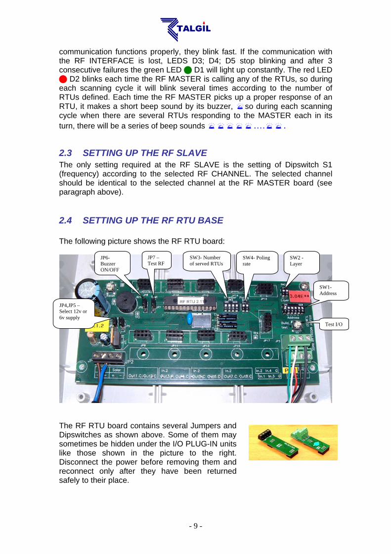
2.4 SETTING UP THE RF RTU BASE The following picture shows the RF RTU board:
The RF RTU board contains several Jumpers and Dipswitches as shown above. Some of them may sometimes be hidden under the I/O PLUG-IN units like those shown in the picture to the right. Disconnect the power before removing them and reconnect only after they have been returned safely to their place.
SW2 - Layer
SW1- Address
SW4- Poling rate
SW3- Number of served RTUs
JP7 –Test RF
JP6- Buzzer ON/OFF
JP4,JP5 – Select 12v or 6v supply
Test I/O

- 10 -
2.4.1 SETTING OF THE RTU ADDRESS SW1- Defines the address of the specific RTU. The addressing uses binary notation (see the appendix about the binary to decimal conversion). Each RTU must have its own unique address in the range 1 to 60.
Notice that RTUs communicating via a REPEATER, occupy two places in the address space, therefore the consecutive address of each such unit must be skipped.
2.4.2 SETTING UP A REPEATER When there is a necessity to turn an RTU into a REPEATER for the benefit of other RTUs having difficulties to directly communicate with the RF MASTER, both the RTU serving as a REPEATER and the other RTUs using its services, need to be informed about the arrangement. The following settings are required: When SW3 on the RTU board is set to a nonzero value, the RTU becomes a REPEATER, and the value of SW3 represents the number of RTUs using the services of the REPEATER. Now the question is how does the REPEATER know exactly which RTUs it is serving? The answer lies in the addresses of those RTUs. The first RTU must have the address of the REPEATER +1, the second must have the address of the REPEATER +3, the third will have the address of the REPEATER + 5 etc… All RTUs that are directly communicating with the MASTER, without using a REPEATER, belong to layer "0". The RTUs that are functioning as REPEATERS belong also to layer "0". Only the RTUs that are communicated via REPEATERS are considered to belong to layer "1". Each units of layer "0" occupies a single address but those who belong to layer “1” occupy 2 addresses, therefore the immediately following address of such RTUs must be skipped. So RTUs that are communicating via repeaters differ from regular RTUs by two things. First they have to be told that they belong to a higher layer in the communication hierarchy (See below about SW2 the layer switch) and they will occupy two addresses instead of one.
Notice that the address of the first RTU communicating through a repeater will be the next address immediately following the address of the REPEATER. The addresses of the other RTUs communicating via the REPEATER will have a gap of 1 from the former RTU address.
- 11 -
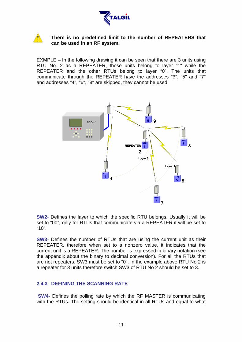
There is no predefined limit to the number of REPEATERS that can be used in an RF system.
EXMPLE – In the following drawing it can be seen that there are 3 units using RTU No. 2 as a REPEATER, those units belong to layer "1" while the REPEATER and the other RTUs belong to layer “0”. The units that communicate through the REPEATER have the addresses "3", "5" and "7" and addresses "4", "6", "8" are skipped, they cannot be used. SW2- Defines the layer to which the specific RTU belongs. Usually it will be set to “00”, only for RTUs that communicate via a REPEATER it will be set to “10”. SW3- Defines the number of RTUs that are using the current unit as their REPEATER, therefore when set to a nonzero value, it indicates that the current unit is a REPEATER. The number is expressed in binary notation (see the appendix about the binary to decimal conversion). For all the RTUs that are not repeaters, SW3 must be set to "0". In the example above RTU No 2 is a repeater for 3 units therefore switch SW3 of RTU No 2 should be set to 3.
2.4.3 DEFINING THE SCANNING RATE SW4- Defines the polling rate by which the RF MASTER is communicating with the RTUs. The setting should be identical in all RTUs and equal to what
- 12 -
has been defined at the UNILINER. The selection of the polling rate is not totally free, it must take into consideration the total number of RTUs in the system or more accurately the highest address to be scanned. The following table shows what will be the highest address recognizable, and the scanning rate selected by each combination of the switch. SW4 – pos 1 pos 2 The canning rate (sec) Highest RTU address 0 0 10 60 1 0 5 31 0 1 2.5 15 1 1 1.25 7
2.4.4 FUNCTIONS OF THE JUMPERS
JP4, JP5 – These two jumpers must be set to the same position. They define the voltage used for powering the RTU. The options are 6 volts or 12 volts. When powered by 6v, 4 “D” type standard alkaline batteries should be used. The 12v DC supply is intended only for powering the system by solar energy with a rechargeable battery. Using dry batteries of 12v is not recommended.
Connecting 12v supply while the jumpers are set to 6v will severely damage the unit.
JP6- When in the upper position, the buzzer is enabled. JP7- When set to the upper position, a request for RF testing mode is sent to the DREAM controller. see below the explanation about the RF test mode.
3. THE VARIOUS MODES OF OPERATION 3.1 START-UP MODE– Right after energizing the RTU or after pushing it's reset button there is an initialization process that starts with 2 short beeps after which the solenoids are closed one by one. 15 seconds later another 2 short beeps
can be heard. 15 seconds more and another 2 beeps indicate the end of the start up mode. The red LED of the slave turns on indicating that the unit is now trying to catch communication with the MASTER. This may take about 10 seconds. If the communication is established, the RTU goes into NORMAL MODE otherwise it will keep trying to catch communication every 30 seconds. 3.2 NORMAL MODE – During normal mode of operation, the RTUs are scanned by the UNILINER via the RF MASTER one by one in a cyclic manner and in a constant rate. In each cycle, every RTU is communicated within its allocated timeslot, which is dictated by its address. During that timeslot, an information exchange takes
- 13 -
place, the required state of the outputs is sent from the UNILINER to the RTU, and the current state of inputs is transmitted back to the UNILINER. The rate of scanning must be identically set both at the UNILINER and at each RTU. When the RF MASTER initiates a scanning cycle there will be a blink of the MASTER's LED and for each response received correctly from any RTU, there will be a short beep sounded by the MASTER's buzzer. At the other end the RF SLAVE which is dormant between the scanning cycles, wakes up at the right timeslot and prepares itself for receiving the transmission of the RF MASTER. This state is indicated by a blink of the SLAVE's LED . Each time a successful information exchange takes place there will be a short beep sound made by the buzzers of both the RTU BASE and the RF SLAVE. If the RTU picks up the signal from the MASTER but the call was not correctly addressed, it will sound a double beep . 3.3 RF TEST MODE The purpose of this test is to check the communication between a specific RTU and the RF MASTER. The TEST mode has to be manually enabled from the UNILINER. When enabled, the request for RF TEST is initiated from the RTU. By setting JP7 to "RF test" (upper position) a test request signal is sent to the UNILINER. When the request is received, it is immediately granted and the RF test starts. During RF TEST mode, the regular scanning of all the RTUs is stopped and the RF MASTER starts communicating solely with the RTU under test. The red LED of the slave is constantly ON . The rate of communication becomes once per second. Each second the RF MASTER transmits a signal, which is addressed to the specific RTU under test. When the signal is picked up by the RTU, it responds by a beep of its buzzer and by sending back an acknowledge signal. The RF MASTER when receiving the acknowledge signal from the RTU, will also sound its buzzer . A successful test results in an endless sequence of beeps, one beep every second at both sides. The RF MASTER will remain in TEST mode until receiving an END OF TEST signal from the RTU (as a result of removing jumper 7) or until the RF TEST is disabled by the user inside the UNILINER. 3.4 WHEN LOOSING COMMUNICATION When the RTU looses communication with the UNILINER, then after three unsuccessful cycles, it will shut down the open outputs and will start seeking the communication signal of the RF MASTER. During this process, every 15-second a double beep will sound, and every 30 seconds the red LED of the SLAVE will turn on for 10 seconds indicating that the receiver has been opened trying to pick up the communication signal. This will continue for 1 hour and then for the sake of energy saving the RTU will start seeking communication only once every hour. When the communication signal is regained, the RTU returns to its previous state, if it was the normal state then it will reopen the outputs that were commanded by the UNILINER to be open.
Notice that if the RF MASTER was OFF for more than an hour, when it is turned ON again, the RTUs may not respond immediately to the calls of the RF MASTER, because they are in energy saving mode. It may take an hour before they start

- 14 -
responding. They can be forced to exit energy saving mode by pushing the RESET button of the RTU.
3.5 TESTING INPUTS AND OUTPUTS During I/O TEST mode the inputs and the outputs of the RTU can be tested. For starting the test process hold down the BUILD TEST button S5 for a few seconds until a long beep sound is heard. After the beep, there will be a ticking sound every second indicating that we are in INPUTS TEST mode. During INPUTS TEST we can test all the inputs, all the jumpers and all the Dipswitches. Any change made will sound the buzzer . Pushing the BUILD TEST button again makes the buzzer sound twice indicating termination of the INPUTS TEST and starting the OUTPUTS TEST. First, all the outputs are commanded to close and then one by one the outputs are commanded to open and after a few seconds they are closed back. The open command is indicated by a single beep and the close command by a double beep
. The end of the process is indicated by two long beeps . 3.6 LOW BATTERY INDICATION When the battery of an RTU gets too low, there will be a LOW BATTERY indication both at the RTU and at the UNILINER. At the RTU, the low battery is indicated by a sound of 3 beeps sounded every few seconds. At the UNILINER, the indication will be at the screens showing the RTUs statuses. When is the battery considered low? It depends on the selected powering level whether 12v or 6v. However the system decides on low battery situation by two criterions: one is the voltage of the battery and the second is the time it takes to recharge the capacitor after execution of an output command. For example, if the powering voltage is 6v, then low battery starts to be signaled when the battery drops to 4.8 volts or when the recharging time is longer than 5 seconds. At this stage the normal operation continues but the user is informed that the battery should be replaced. If the voltage drops further to 3.6v the beeping stops and all outputs will be shut down, since the unit is no longer able to continue communicating with the RF MASTER.

- 15 -
4. SUMMARY of SOUNDS and LIGHTS
Long beep - Short beep - A tick - Long blink- Short blink- 4.1 RTU+SLAVE during START UP USER ACTION: connecting power or pushing the RESET button RTU ACTION: closing all outputs
RTU BUZZER: 15 sec 15 sec
SLAVE LED: 30 sec lighting =<10 sec
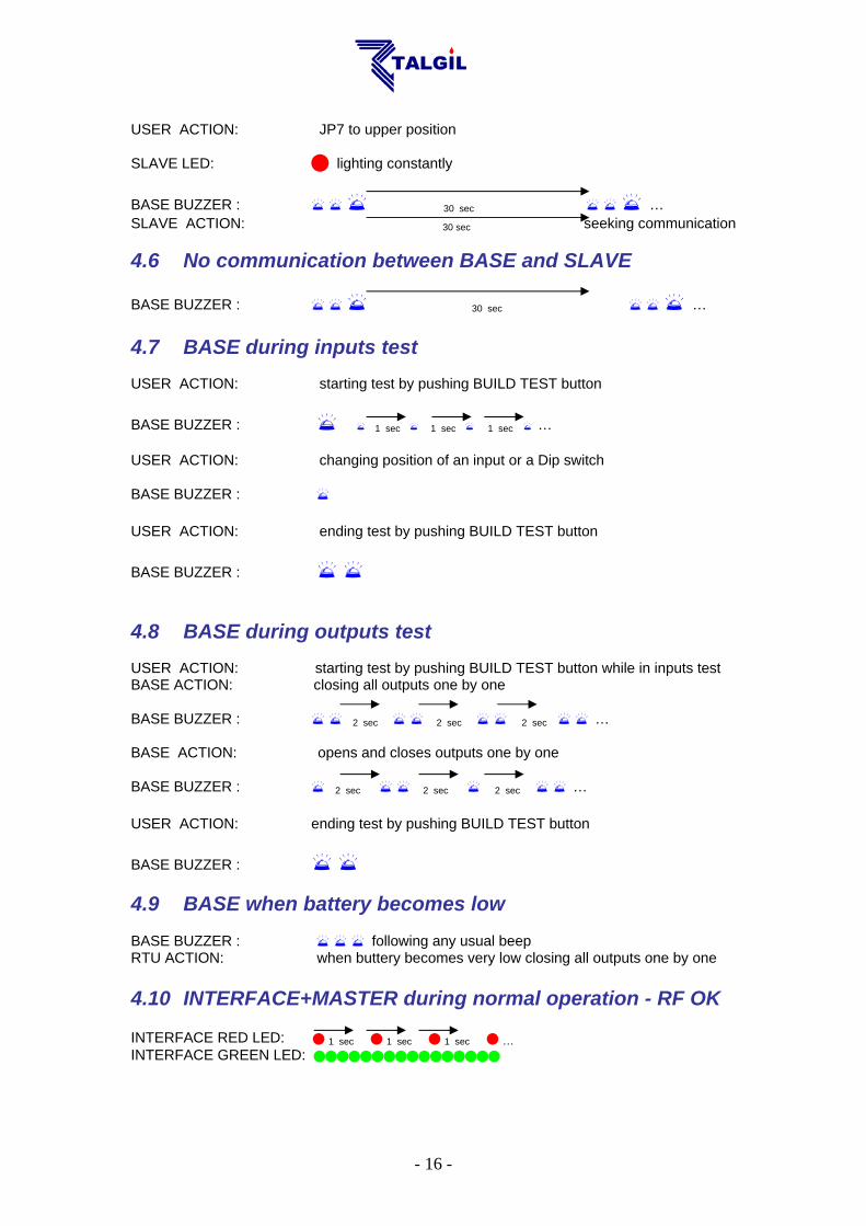
SLAVE ACTION: 30 sec seeking communication 4.2 RTU BASE+SLAVE during normal communication SLAVE LED: 1 / 2.5 / 5 / 10 sec 1 / 2.5 / 5 / 10 sec 1 / 2.5 / 5 / 10 sec … BASE+SLAVE BUZZERS : 1 / 2.5 / 5 / 10 sec 1 / 2.5 / 5 / 10 sec 1 / 2.5 / 5 / 10 sec … When incorrect RTU address defined BASE+SLAVE BUZZERS : 1 / 2.5 / 5 / 10 sec 1 / 2.5 / 5 / 10 sec 1 / 2.5 / 5 / 10 sec … 4.3 BASE+SLAVE while losing communication SLAVE LED: 30 sec lighting =<10 sec BASe BUZZER: 15 sec 15 sec SLAVE ACTION: 30 sec seeking communication After 1 hour will go into energy saving mode and seek communication only once in an hour 4.4 BASE+SLAVE during RF test - COMMUNICATION OK USER ACTION: JP7 to upper position SLAVE LED: lighting constantly BASE+SLAVE BUZZERS : 1 sec 1 sec 1 sec … 4.5 BASE+SLAVE during RF test – NOT RECEIVING
- 16 -
USER ACTION: JP7 to upper position SLAVE LED: lighting constantly
BASE BUZZER : 30 sec … SLAVE ACTION: 30 sec seeking communication 4.6 No communication between BASE and SLAVE
BASE BUZZER : 30 sec … 4.7 BASE during inputs test USER ACTION: starting test by pushing BUILD TEST button
BASE BUZZER : 1 sec 1 sec 1 sec … USER ACTION: changing position of an input or a Dip switch BASE BUZZER : USER ACTION: ending test by pushing BUILD TEST button BASE BUZZER : 4.8 BASE during outputs test USER ACTION: starting test by pushing BUILD TEST button while in inputs test BASE ACTION: closing all outputs one by one BASE BUZZER : 2 sec 2 sec 2 sec … BASE ACTION: opens and closes outputs one by one BASE BUZZER : 2 sec 2 sec 2 sec … USER ACTION: ending test by pushing BUILD TEST button
BASE BUZZER : 4.9 BASE when battery becomes low BASE BUZZER : following any usual beep RTU ACTION: when buttery becomes very low closing all outputs one by one 4.10 INTERFACE+MASTER during normal operation - RF OK INTERFACE RED LED: 1 sec 1 sec 1 sec … INTERFACE GREEN LED:
- 17 -
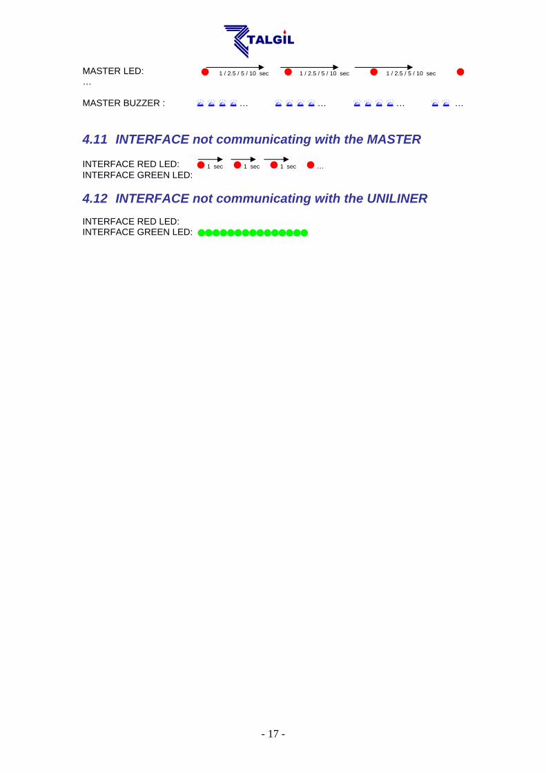
MASTER LED: 1 / 2.5 / 5 / 10 sec 1 / 2.5 / 5 / 10 sec 1 / 2.5 / 5 / 10 sec … MASTER BUZZER : … … … … 4.11 INTERFACE not communicating with the MASTER INTERFACE RED LED: 1 sec 1 sec 1 sec … INTERFACE GREEN LED: 4.12 INTERFACE not communicating with the UNILINER INTERFACE RED LED: INTERFACE GREEN LED:
- 18 -
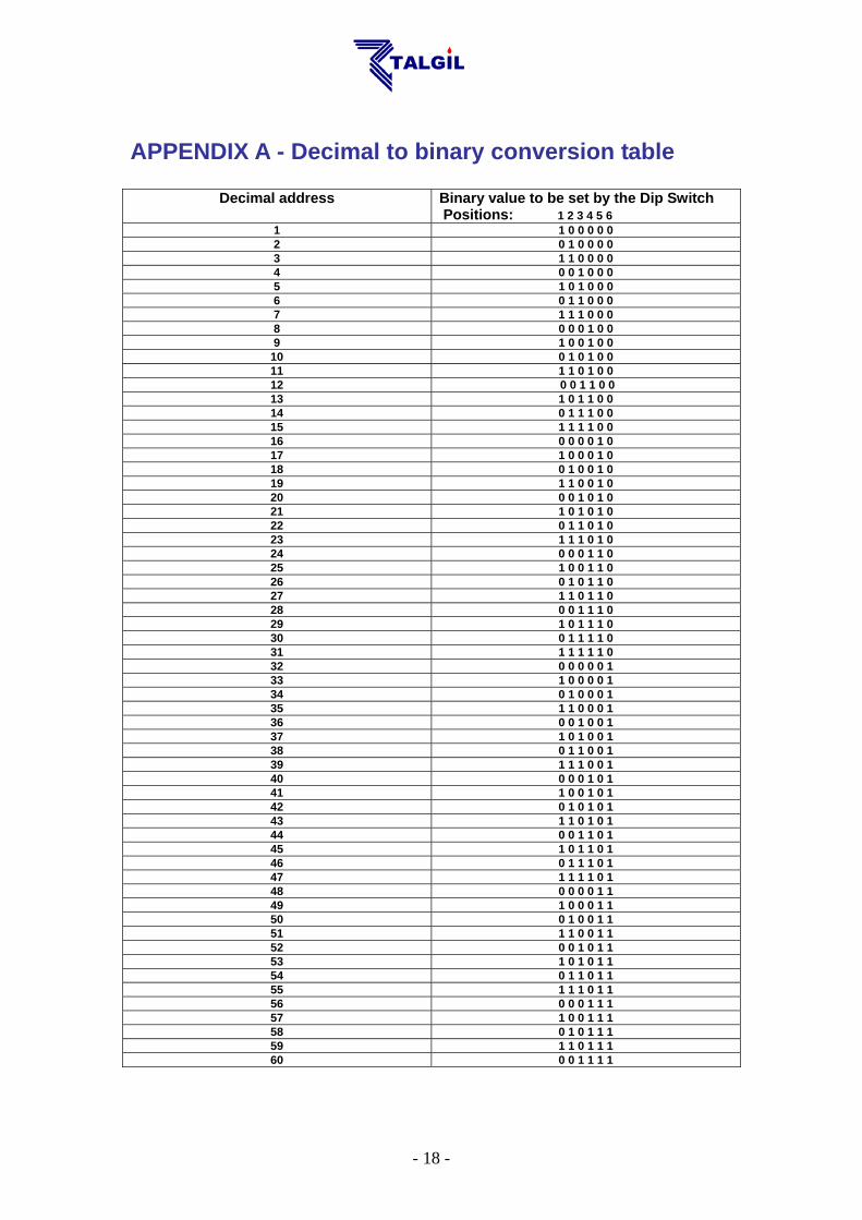
APPENDIX A - Decimal to binary conversion table
Decimal address Binary value to be set by the Dip Switch Positions: 1 2 3 4 5 6
1 1 0 0 0 0 0 2 0 1 0 0 0 0 3 1 1 0 0 0 0 4 0 0 1 0 0 0 5 1 0 1 0 0 0 6 0 1 1 0 0 0 7 1 1 1 0 0 0 8 0 0 0 1 0 0 9 1 0 0 1 0 0
10 0 1 0 1 0 0 11 1 1 0 1 0 0 12 0 0 1 1 0 0 13 1 0 1 1 0 0 14 0 1 1 1 0 0 15 1 1 1 1 0 0 16 0 0 0 0 1 0 17 1 0 0 0 1 0 18 0 1 0 0 1 0 19 1 1 0 0 1 0 20 0 0 1 0 1 0 21 1 0 1 0 1 0 22 0 1 1 0 1 0 23 1 1 1 0 1 0 24 0 0 0 1 1 0 25 1 0 0 1 1 0 26 0 1 0 1 1 0 27 1 1 0 1 1 0 28 0 0 1 1 1 0 29 1 0 1 1 1 0 30 0 1 1 1 1 0 31 1 1 1 1 1 0 32 0 0 0 0 0 1 33 1 0 0 0 0 1 34 0 1 0 0 0 1 35 1 1 0 0 0 1 36 0 0 1 0 0 1 37 1 0 1 0 0 1 38 0 1 1 0 0 1 39 1 1 1 0 0 1 40 0 0 0 1 0 1 41 1 0 0 1 0 1 42 0 1 0 1 0 1 43 1 1 0 1 0 1 44 0 0 1 1 0 1 45 1 0 1 1 0 1 46 0 1 1 1 0 1 47 1 1 1 1 0 1 48 0 0 0 0 1 1 49 1 0 0 0 1 1 50 0 1 0 0 1 1 51 1 1 0 0 1 1 52 0 0 1 0 1 1 53 1 0 1 0 1 1 54 0 1 1 0 1 1 55 1 1 1 0 1 1 56 0 0 0 1 1 1 57 1 0 0 1 1 1 58 0 1 0 1 1 1 59 1 1 0 1 1 1 60 0 0 1 1 1 1
19
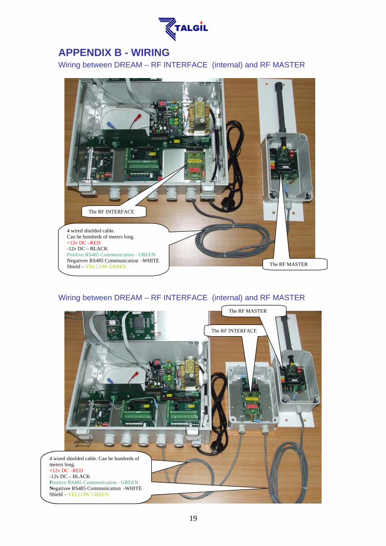
APPENDIX B - WIRING Wiring between DREAM – RF INTERFACE (internal) and RF MASTER Wiring between DREAM – RF INTERFACE (internal) and RF MASTER
The RF INTERFACE
4 wired shielded cable. Can be hundreds of meters long. +12v DC –RED -12v DC – BLACK Positive RS485 Communication - GREEN Negativee RS485 Communication -WHITE Shield – YELLOW GRREN The RF MASTER
The RF INTERFACE
The RF MASTER
4 wired shielded cable. Can be hundreds of meters long. +12v DC –RED -12v DC – BLACK Positive RS485 Communication - GREEN Negativee RS485 Communication -WHITE Shield – YELLOW GRREN
4 wired shielded cable. Can be hundreds of meters long. +12v DC –RED -12v DC – BLACK Positive RS485 Communication - GREEN Negativee RS485 Communication -WHITE Shield – YELLOW GRREN
20
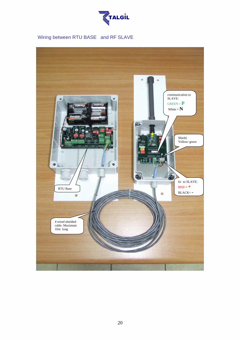
Wiring between RTU BASE and RF SLAVE
4 wired shielded cable. Maximum 10m long
Shield: Yellow/ green
6v to SLAVE: RED = + BLACK= -
communication to SLAVE: GREEN = P
White = N
RTU Base
21
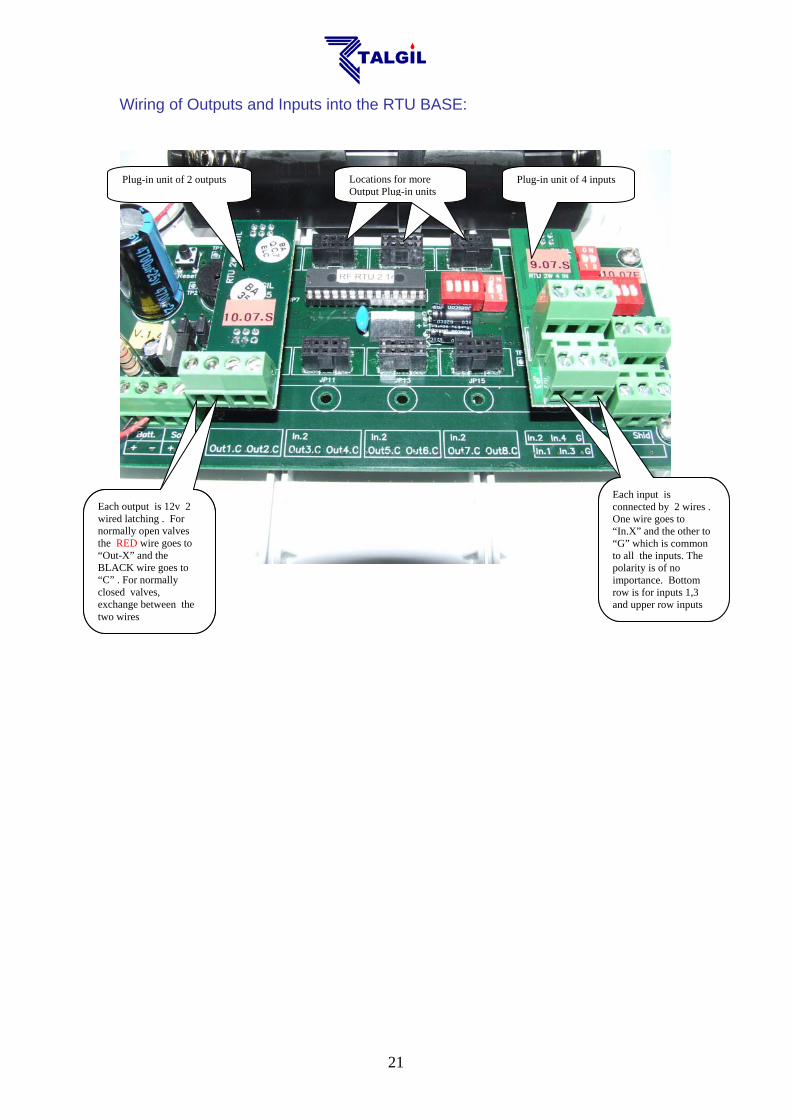
Wiring of Outputs and Inputs into the RTU BASE:
Plug-in unit of 2 outputs Plug-in unit of 4 inputs Locations for more Output Plug-in unitsLocations for more Output Plug-in unitsLocations for more Output Plug-in units
Each output is 12v 2 wired latching . For normally open valves the RED wire goes to “Out-X” and the BLACK wire goes to “C” . For normally closed valves, exchange between the two wires
Each input is connected by 2 wires . One wire goes to “In.X” and the other to “G” which is common to all the inputs. The polarity is of no importance
Each output is 12v 2 wired latching . For normally open valves the RED wire goes to “Out-X” and the BLACK wire goes to “C” . For normally closed valves, exchange between the two wires
Each input is connected by 2 wires . One wire goes to “In.X” and the other to “G” which is common to all the inputs. The polarity is of no importance. Bottom row is for inputs 1,3 and upper row inputs
22
APPENDIX C – THE RF EAR The RF EAR is a very efficient monitoring tool that supplies valuable information about the communication between the RF MASTER and the SLAVES of a particular system to which it is tuned. The RF EAR contains an RF receiver/transmitter, which resembles the RF MASTER but functions in a totally different way – it does not transmit anything but it is continuously open for reception of any transmissions made by the members of the system. The RF EAR picks up only data transfer using the communication protocol utilized by Talgil RF systems and only if it is in the selected frequency. Therefore, the collected information shows the behavior of the particular system being tested, the information is displayed at a real time basis on the screen of a mobile PC and it is continuously recorded for later inspection. By moving around with the RF EAR and recording the reception quality at the various RTU locations and at the center, one can identify the week points of the system and decide about the solutions. Usually the receiver/transmitter unit of the RF EAR will be installed on a long PVC pole that enables raising it high at the places being checked. HOW TO USE THE RF EAR ?
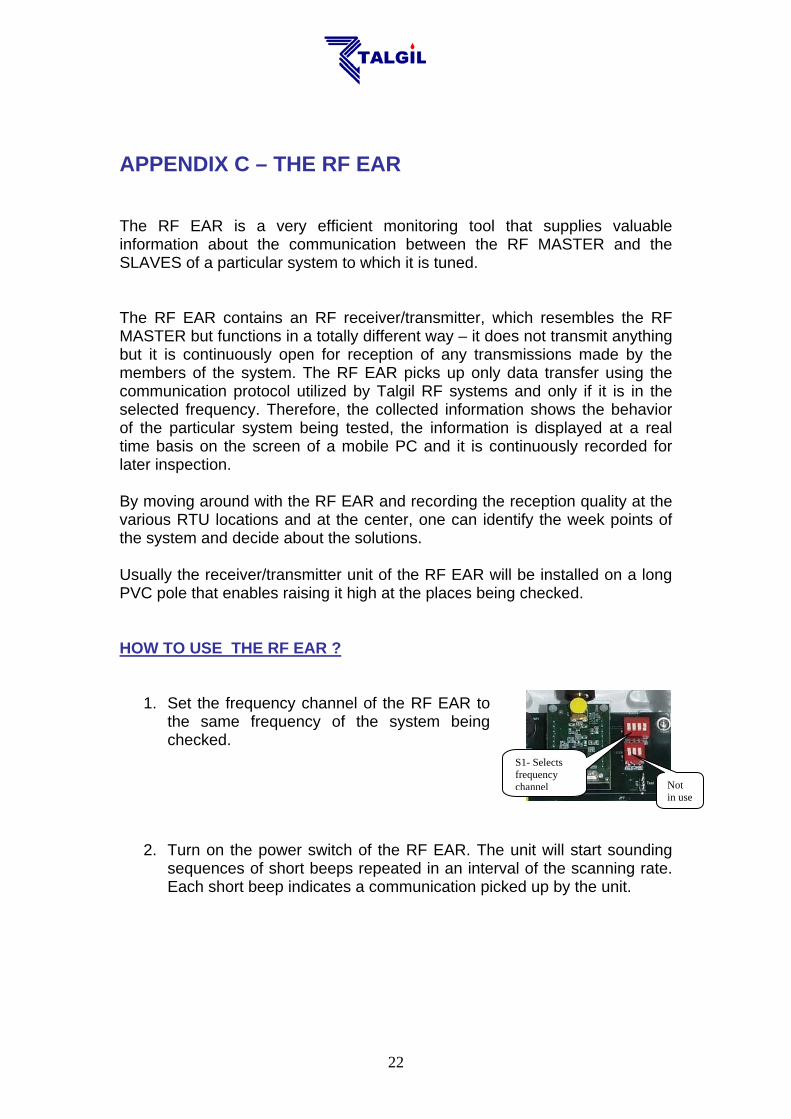
1. Set the frequency channel of the RF EAR to the same frequency of the system being checked.
2. Turn on the power switch of the RF EAR. The unit will start sounding sequences of short beeps repeated in an interval of the scanning rate. Each short beep indicates a communication picked up by the unit.
S1- Selects frequency channel Not
in use
23
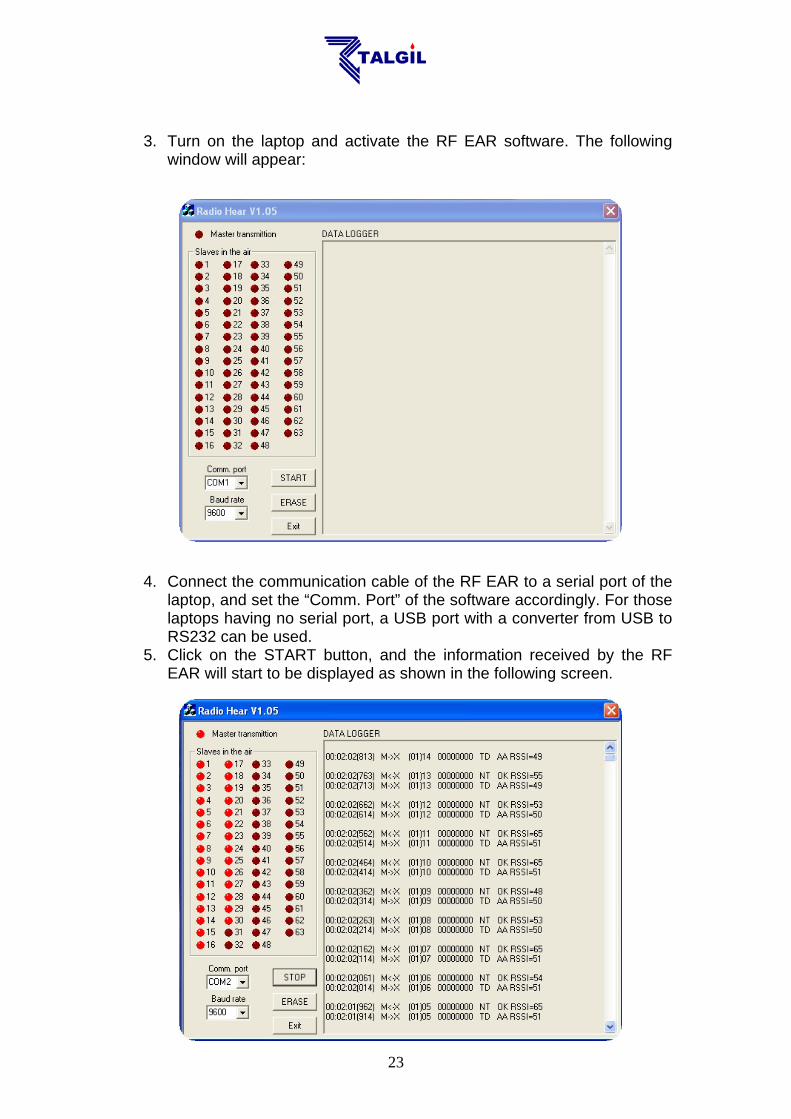
3. Turn on the laptop and activate the RF EAR software. The following window will appear:
4. Connect the communication cable of the RF EAR to a serial port of the
laptop, and set the “Comm. Port” of the software accordingly. For those laptops having no serial port, a USB port with a converter from USB to RS232 can be used.
5. Click on the START button, and the information received by the RF EAR will start to be displayed as shown in the following screen.

24
The display is refreshed each scanning cycle. The drawings of the LEDS on the left side indicate the status of communication with each of the RF SLAVES (or with each RTU). An RTU, which responds properly, will be indicated by a LED lighting constantly. An RTU that did not respond the call of the MASTER will be indicated by a blinking LED. The RTUs that were not called by the MASTER either because they are undefined or because the call of the MASTER was not received remain dark. On the right side of the window appear rows of characters that describe the information transmitted either by the MASTER or by one of the SLAVES. The rows are shifted downward with each new row received by the RF EAR. The following row contains information about the MASTER’s transmission : The response of the slave has the following format: Notice that in the 8 bits string describing the status of the outputs or the inputs the rightmost digit represents the lower Output/Input bit. When an RTU is defined to communicate through a REPEATER, there will be 4 rows describing the process: 1) the call of the MASTER; 2) the transfer of the call to the SLAVE by the REPEATER; 3) the response of the SLAVE and 4) the transfer of the response to the MASTER by the REPEATER.
The time at which the communication took place.. The brackets contain milliseconds.
M – > X indicates a call from the MASTER to SLAVE - X
The number of the SLAVE -X is 9. The number in brackets is the selected frequency channel.
The status of the outputs-each bit represents 1 out of 8 outputs. “0” means closed, “1” means open.
The RSSI indicates the strength of the MASTER’S signal: 41-73 = Strong 34-40 = Medium 20-33 = Low
M <– X indicates the response from SLAVE - X to the MASTER.
The status of the inputs-each bit represents 1 out of 4 outputs. “0” means open contact, “1” means closed contact.
The RSSI indicates the strength of the SLAVE’S signal: 41-73 = Strong 34-40 = Medium 20-33 = Low
25
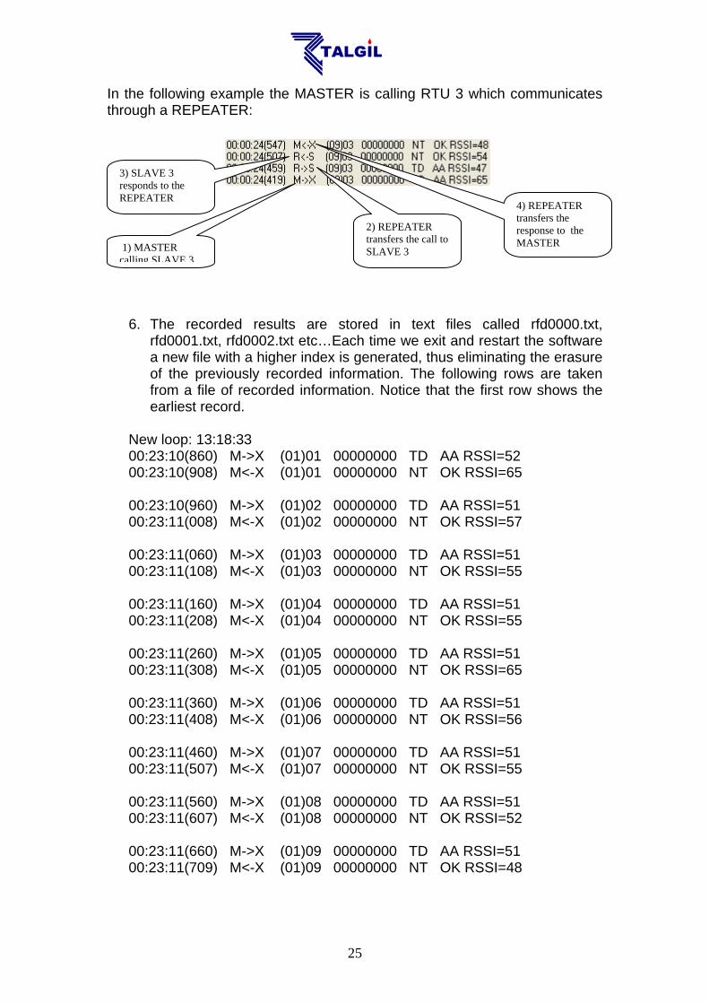
In the following example the MASTER is calling RTU 3 which communicates through a REPEATER:
6. The recorded results are stored in text files called rfd0000.txt,
rfd0001.txt, rfd0002.txt etc…Each time we exit and restart the software a new file with a higher index is generated, thus eliminating the erasure of the previously recorded information. The following rows are taken from a file of recorded information. Notice that the first row shows the earliest record.
New loop: 13:18:33 00:23:10(860) M->X (01)01 00000000 TD AA RSSI=52 00:23:10(908) M<-X (01)01 00000000 NT OK RSSI=65 00:23:10(960) M->X (01)02 00000000 TD AA RSSI=51 00:23:11(008) M<-X (01)02 00000000 NT OK RSSI=57 00:23:11(060) M->X (01)03 00000000 TD AA RSSI=51 00:23:11(108) M<-X (01)03 00000000 NT OK RSSI=55 00:23:11(160) M->X (01)04 00000000 TD AA RSSI=51 00:23:11(208) M<-X (01)04 00000000 NT OK RSSI=55 00:23:11(260) M->X (01)05 00000000 TD AA RSSI=51 00:23:11(308) M<-X (01)05 00000000 NT OK RSSI=65 00:23:11(360) M->X (01)06 00000000 TD AA RSSI=51 00:23:11(408) M<-X (01)06 00000000 NT OK RSSI=56 00:23:11(460) M->X (01)07 00000000 TD AA RSSI=51 00:23:11(507) M<-X (01)07 00000000 NT OK RSSI=55 00:23:11(560) M->X (01)08 00000000 TD AA RSSI=51 00:23:11(607) M<-X (01)08 00000000 NT OK RSSI=52 00:23:11(660) M->X (01)09 00000000 TD AA RSSI=51 00:23:11(709) M<-X (01)09 00000000 NT OK RSSI=48
1) MASTER calling SLAVE 3
2) REPEATER transfers the call to SLAVE 3
3) SLAVE 3 responds to the REPEATER
4) REPEATER transfers the response to the MASTER

26
00:23:11(760) M->X (01)10 00000000 TD AA RSSI=51 00:23:11(809) M<-X (01)10 00000000 NT OK RSSI=55 00:23:11(860) M->X (01)11 00000000 TD AA RSSI=51 00:23:11(908) M<-X (01)11 00000000 NT OK RSSI=56 00:23:11(960) M->X (01)12 00000000 TD AA RSSI=51 00:23:12(008) M<-X (01)12 00000000 NT OK RSSI=52 00:23:12(060) M->X (01)13 00000000 TD AA RSSI=51 00:23:12(107) M<-X (01)13 00000000 NT OK RSSI=54
******************** ******************** ******************** ******************** ******************** ********
Each asterisk (*) that follows a communication cycle indicates another cycle which terminated with identical results to the previous one.

27
APPENDIX D - Catalog numbers of main boards
Related Documents