Unilamellar vesicle formation and encapsulation by microfluidic jetting Jeanne C. Stachowiak*, David L. Richmond † , Thomas H. Li*, Allen P. Liu † , Sapun H. Parekh ‡ , and Daniel A. Fletcher †‡§ *Department of Mechanical Engineering, † Biophysics Graduate Group, and ‡ Department of Bioengineering, University of California, Berkeley, CA 94720 Edited by David Deamer, University of California, Santa Cruz, CA, and accepted by the Editorial Board January 24, 2008 (received for review November 15, 2007) Compartmentalization of biomolecules within lipid membranes is a fundamental requirement of living systems and an essential feature of many pharmaceutical therapies. However, applications of membrane-enclosed solutions of proteins, DNA, and other biologically active compounds have been limited by the difficulty of forming unilamellar vesicles with controlled contents in a repeatable manner. Here, we demonstrate a method for simulta- neously creating and loading giant unilamellar vesicles (GUVs) using a pulsed microfluidic jet. Akin to blowing a bubble, the microfluidic jet deforms a planar lipid bilayer into a vesicle that is filled with solution from the jet and separates from the planar bilayer. In contrast with existing techniques, our method rapidly generates multiple monodisperse, unilamellar vesicles containing solutions of unrestricted composition and molecular weight. Using the microfluidic jetting technique, we demonstrate repeatable encapsulation of 500-nm particles into GUVs and show that func- tional pore proteins can be incorporated into the vesicle membrane to mediate transport. The ability of microfluidic jetting to control- lably encapsulate solutions inside of GUVs creates new opportu- nities for the study and use of compartmentalized biomolecular systems in science, industry, and medicine. vortex liposome drug delivery synthetic biology E ncapsulation of enzymes in lipid vesicles was first attempted by Sessa and Weissmann in 1970 (1). Since then, vesicles encapsulating biologically active compounds have been used as chemical microreactors (2), delivery vehicles for pharmaceuti- cals (3), and platforms for synthetic biological systems (4, 5). Because mixtures of lipids and biomolecules will not spontane- ously organize into solution-encapsulating vesicles of defined composition and size, several methods have been devised to form and load vesicles including swelling (6), extrusion (7), electro- formation (8), electroinjection (9), and reverse evaporation and emulsion (10, 11). Among the most important properties of a vesicle formation and loading technique are control of (i) membrane unilamel- larity, (ii) vesicle size, and (iii) internal solution concentration without solute-specific selectivity. Furthermore, practical appli- cations of vesicle encapsulation require high encapsulation ef- ficiency to minimize needed solution volume, high-throughput formation, and the ability to examine the vesicle and any associated reactions immediately after loading. Furthermore, In applications to study in vitro protein assemblies (12) and cell-like membrane deformations (13), giant unilamellar vesicles (GUVs) with diameters 10 m are desirable to facilitate direct visual- ization of internal behavior by light microscopy. Although each existing vesicle-formation technique achieves some of these criteria, none enables vesicle formation and encapsulation with all of these properties. For example, swelling typically results in the formation of multilamellar vesicles (MLVs) that vary widely in size and encapsulate with low, solute-specific efficiency (2). Electroformation can produce GUVs with diameters 10 m. However, vesicle diameter is not controlled, and the technique is restricted to low-ionic-strength conditions, limiting its applicability for encapsulation of biomol- ecules (14). The size uniformity of GUVs and the unilamellarity of MLVs made by several techniques (6, 8, 10) can be greatly enhanced by extruding the vesicles through filters with submi- crometer pores, although the resulting vesicles are limited to the size of the pores and have the same internal composition as the original vesicles (15). The reverse emulsion technique offers the advantage of solute-independent encapsulation. However, the size of vesicles produced by reverse emulsion is not directly controllable and throughput is limited (16). Recently, several groups have reported the high-throughput production of mono- disperse single- and double-emulsion structures using microde- vices that hydrodynamically focus fluid streams (17–19) and pulsed microfluidic jets that deform interfaces (20), although none has been shown to form unilamellar vesicles, an essential requirement for many applications. Here, we demonstrate the formation and loading of GUVs by microf luidic jetting-induced deformation of a planar lipid bilayer (Fig. 1a). This technique relies on a precisely controlled pulsatile liquid jet directed into a unilamellar lipid bilayer formed be- tween two aqueous phases (Fig. 1b). One GUV is formed for each pulse of the liquid jet against the lipid bilayer, which remains intact after the vesicle is formed, and multiple mono- disperse vesicles are formed by repeated pulses against the same lipid bilayer (Fig. 1c). Using high-speed video microscopy, we examine the vesicle-formation process to investigate the fluid- membrane interactions that determine vesicle size and enable vesicle separation from the planar bilayer. Finally, we encapsu- late a solution of 500-nm-diameter particles and demons- trate protein pore-mediated transport of solutes across vesicle boundaries. Results and Discussion Vesicles produced by microfluidic jetting against a planar lipid bilayer are highly uniform in size and robust, outlasting the observation time of several hours after formation. The average vesicle diameter was 208 m based on a total measured popu- lation of 46 GUVs, varying by 2–3% for a given series of pulses and by 7% for different planar bilayers and nozzles of nomi- nally the same size, 40 m (Fig. 1 c and d). Multiple vesicles can be created in rapid succession because lipid molecules capable of replenishing the planar bilayer are available in high concentra- tion (in the supporting oil phase around the black film). High- throughput formation of thousands of vesicles per minute is feasible based on a formation time of 5 ms per GUV but was not the objective of this work. Because the vesicle is created from a Author contributions: J.C.S., D.L.R., T.H.L., A.P.L., S.H.P., and D.A.F. designed research; J.C.S., D.L.R., T.H.L., A.P.L., and S.H.P. performed research; J.C.S., D.L.R., T.H.L., A.P.L., S.H.P., and D.A.F. analyzed data; and J.C.S., D.L.R., and D.A.F. wrote the paper. The authors declare no conflict of interest. This article is a PNAS Direct Submission. D.D. is a guest editor invited by the Editorial Board. § To whom correspondence should be addressed at: Department of Bioengineering, University of California, 608B Stanley Hall 3220, Berkeley, CA 94720. E-mail: fl[email protected]. This article contains supporting information online at www.pnas.org/cgi/content/full/ 0710875105/DC1. © 2008 by The National Academy of Sciences of the USA www.pnas.orgcgidoi10.1073pnas.0710875105 PNAS March 25, 2008 vol. 105 no. 12 4697– 4702 BIOPHYSICS Downloaded by guest on December 1, 2021

Welcome message from author
This document is posted to help you gain knowledge. Please leave a comment to let me know what you think about it! Share it to your friends and learn new things together.
Transcript

Unilamellar vesicle formation and encapsulationby microfluidic jettingJeanne C. Stachowiak*, David L. Richmond†, Thomas H. Li*, Allen P. Liu†, Sapun H. Parekh‡, and Daniel A. Fletcher†‡§
*Department of Mechanical Engineering, †Biophysics Graduate Group, and ‡Department of Bioengineering, University of California, Berkeley, CA 94720
Edited by David Deamer, University of California, Santa Cruz, CA, and accepted by the Editorial Board January 24, 2008 (received for reviewNovember 15, 2007)
Compartmentalization of biomolecules within lipid membranes isa fundamental requirement of living systems and an essentialfeature of many pharmaceutical therapies. However, applicationsof membrane-enclosed solutions of proteins, DNA, and otherbiologically active compounds have been limited by the difficultyof forming unilamellar vesicles with controlled contents in arepeatable manner. Here, we demonstrate a method for simulta-neously creating and loading giant unilamellar vesicles (GUVs)using a pulsed microfluidic jet. Akin to blowing a bubble, themicrofluidic jet deforms a planar lipid bilayer into a vesicle that isfilled with solution from the jet and separates from the planarbilayer. In contrast with existing techniques, our method rapidlygenerates multiple monodisperse, unilamellar vesicles containingsolutions of unrestricted composition and molecular weight. Usingthe microfluidic jetting technique, we demonstrate repeatableencapsulation of 500-nm particles into GUVs and show that func-tional pore proteins can be incorporated into the vesicle membraneto mediate transport. The ability of microfluidic jetting to control-lably encapsulate solutions inside of GUVs creates new opportu-nities for the study and use of compartmentalized biomolecularsystems in science, industry, and medicine.
vortex � liposome � drug delivery � synthetic biology
Encapsulation of enzymes in lipid vesicles was first attemptedby Sessa and Weissmann in 1970 (1). Since then, vesicles
encapsulating biologically active compounds have been used aschemical microreactors (2), delivery vehicles for pharmaceuti-cals (3), and platforms for synthetic biological systems (4, 5).Because mixtures of lipids and biomolecules will not spontane-ously organize into solution-encapsulating vesicles of definedcomposition and size, several methods have been devised to formand load vesicles including swelling (6), extrusion (7), electro-formation (8), electroinjection (9), and reverse evaporation andemulsion (10, 11).
Among the most important properties of a vesicle formationand loading technique are control of (i) membrane unilamel-larity, (ii) vesicle size, and (iii) internal solution concentrationwithout solute-specific selectivity. Furthermore, practical appli-cations of vesicle encapsulation require high encapsulation ef-ficiency to minimize needed solution volume, high-throughputformation, and the ability to examine the vesicle and anyassociated reactions immediately after loading. Furthermore, Inapplications to study in vitro protein assemblies (12) and cell-likemembrane deformations (13), giant unilamellar vesicles (GUVs)with diameters �10 �m are desirable to facilitate direct visual-ization of internal behavior by light microscopy.
Although each existing vesicle-formation technique achievessome of these criteria, none enables vesicle formation andencapsulation with all of these properties. For example, swellingtypically results in the formation of multilamellar vesicles(MLVs) that vary widely in size and encapsulate with low,solute-specific efficiency (2). Electroformation can produceGUVs with diameters �10 �m. However, vesicle diameter is notcontrolled, and the technique is restricted to low-ionic-strengthconditions, limiting its applicability for encapsulation of biomol-
ecules (14). The size uniformity of GUVs and the unilamellarityof MLVs made by several techniques (6, 8, 10) can be greatlyenhanced by extruding the vesicles through filters with submi-crometer pores, although the resulting vesicles are limited to thesize of the pores and have the same internal composition as theoriginal vesicles (15). The reverse emulsion technique offersthe advantage of solute-independent encapsulation. However,the size of vesicles produced by reverse emulsion is not directlycontrollable and throughput is limited (16). Recently, severalgroups have reported the high-throughput production of mono-disperse single- and double-emulsion structures using microde-vices that hydrodynamically focus fluid streams (17–19) andpulsed microfluidic jets that deform interfaces (20), althoughnone has been shown to form unilamellar vesicles, an essentialrequirement for many applications.
Here, we demonstrate the formation and loading of GUVs bymicrofluidic jetting-induced deformation of a planar lipid bilayer(Fig. 1a). This technique relies on a precisely controlled pulsatileliquid jet directed into a unilamellar lipid bilayer formed be-tween two aqueous phases (Fig. 1b). One GUV is formed foreach pulse of the liquid jet against the lipid bilayer, whichremains intact after the vesicle is formed, and multiple mono-disperse vesicles are formed by repeated pulses against the samelipid bilayer (Fig. 1c). Using high-speed video microscopy, weexamine the vesicle-formation process to investigate the fluid-membrane interactions that determine vesicle size and enablevesicle separation from the planar bilayer. Finally, we encapsu-late a solution of 500-nm-diameter particles and demons-trate protein pore-mediated transport of solutes across vesicleboundaries.
Results and DiscussionVesicles produced by microfluidic jetting against a planar lipidbilayer are highly uniform in size and robust, outlasting theobservation time of several hours after formation. The averagevesicle diameter was 208 �m based on a total measured popu-lation of 46 GUVs, varying by 2–3% for a given series of pulsesand by �7% for different planar bilayers and nozzles of nomi-nally the same size, 40 �m (Fig. 1 c and d). Multiple vesicles canbe created in rapid succession because lipid molecules capable ofreplenishing the planar bilayer are available in high concentra-tion (in the supporting oil phase around the black film). High-throughput formation of thousands of vesicles per minute isfeasible based on a formation time of 5 ms per GUV but was notthe objective of this work. Because the vesicle is created from a
Author contributions: J.C.S., D.L.R., T.H.L., A.P.L., S.H.P., and D.A.F. designed research;J.C.S., D.L.R., T.H.L., A.P.L., and S.H.P. performed research; J.C.S., D.L.R., T.H.L., A.P.L., S.H.P.,and D.A.F. analyzed data; and J.C.S., D.L.R., and D.A.F. wrote the paper.
The authors declare no conflict of interest.
This article is a PNAS Direct Submission. D.D. is a guest editor invited by the Editorial Board.
§To whom correspondence should be addressed at: Department of Bioengineering, Universityof California, 608B Stanley Hall 3220, Berkeley, CA 94720. E-mail: [email protected].
This article contains supporting information online at www.pnas.org/cgi/content/full/0710875105/DC1.
© 2008 by The National Academy of Sciences of the USA
www.pnas.org�cgi�doi�10.1073�pnas.0710875105 PNAS � March 25, 2008 � vol. 105 � no. 12 � 4697–4702
BIO
PHYS
ICS
Dow
nloa
ded
by g
uest
on
Dec
embe
r 1,
202
1
single lipid bilayer (21), we expect only unilamellar vesicles to beformed with this technique. Furthermore, because this tech-nique relies on large (relative to molecular radii) physicaldeformations of a planar lipid bilayer to simultaneously formvesicles and encapsulate solutes inside of them, we expect that awide range of solutions can be encapsulated within vesicleswithout dependence on specific properties of the solutes such asmolecular weight or charge.
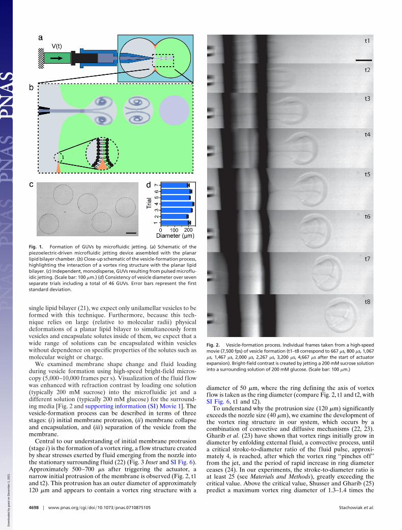
We examined membrane shape change and fluid loadingduring vesicle formation using high-speed bright-field micros-copy (5,000–10,000 frames per s). Visualization of the fluid flowwas enhanced with refraction contrast by loading one solution(typically 200 mM sucrose) into the microfluidic jet and adifferent solution (typically 200 mM glucose) for the surround-ing media [Fig. 2 and supporting information (SI) Movie 1]. Thevesicle-formation process can be described in terms of threestages: (i) initial membrane protrusion, (ii) membrane collapseand encapsulation, and (iii) separation of the vesicle from themembrane.
Central to our understanding of initial membrane protrusion(stage i) is the formation of a vortex ring, a flow structure createdby shear stresses exerted by fluid emerging from the nozzle intothe stationary surrounding fluid (22) (Fig. 3 Inset and SI Fig. 6).Approximately 500–700 �s after triggering the actuator, anarrow initial protrusion of the membrane is observed (Fig. 2, t1and t2). This protrusion has an outer diameter of approximately120 �m and appears to contain a vortex ring structure with a
diameter of 50 �m, where the ring defining the axis of vortexflow is taken as the ring diameter (compare Fig. 2, t1 and t2, withSI Fig. 6, t1 and t2).
To understand why the protrusion size (120 �m) significantlyexceeds the nozzle size (40 �m), we examine the development ofthe vortex ring structure in our system, which occurs by acombination of convective and diffusive mechanisms (22, 23).Gharib et al. (23) have shown that vortex rings initially grow indiameter by enfolding external f luid, a convective process, untila critical stroke-to-diameter ratio of the fluid pulse, approxi-mately 4, is reached, after which the vortex ring ‘‘pinches off’’from the jet, and the period of rapid increase in ring diameterceases (24). In our experiments, the stroke-to-diameter ratio isat least 25 (see Materials and Methods), greatly exceeding thecritical value. Above the critical value, Shusser and Gharib (25)predict a maximum vortex ring diameter of 1.3–1.4 times the
Fig. 1. Formation of GUVs by microfluidic jetting. (a) Schematic of thepiezoelectric-driven microfluidic jetting device assembled with the planarlipid bilayer chamber. (b) Close-up schematic of the vesicle-formation process,highlighting the interaction of a vortex ring structure with the planar lipidbilayer. (c) Independent, monodisperse, GUVs resulting from pulsed microflu-idic jetting. (Scale bar: 100 �m.) (d) Consistency of vesicle diameter over sevenseparate trials including a total of 46 GUVs. Error bars represent the firststandard deviation.
Fig. 2. Vesicle-formation process. Individual frames taken from a high-speedmovie (7,500 fps) of vesicle formation (t1–t8 correspond to 667 �s, 800 �s, 1,067�s, 1,467 �s, 2,000 �s, 2,267 �s, 3,200 �s, 4,667 �s after the start of actuatorexpansion). Bright-field contrast is created by jetting a 200 mM sucrose solutioninto a surrounding solution of 200 mM glucose. (Scale bar: 100 �m.)
4698 � www.pnas.org�cgi�doi�10.1073�pnas.0710875105 Stachowiak et al.
Dow
nloa
ded
by g
uest
on
Dec
embe
r 1,
202
1

initial jet diameter from convective growth. This predictioncorresponds to an expected vortex ring diameter of 50–60 �mbased on the 40-�m nozzle diameter used in our system, in goodagreement with the observed value of 50 �m. The Reynoldsnumber, based on initial jet diameter and speed, is approxi-mately 80 (see Materials and Methods), justifying the use of thisconvective analysis.
Vortex rings grow in outer diameter and eventually dissipateby entraining fluid in their vicinity. As fluid is entrained, themomentum of the vortex structure diffuses away from the ring.The length scale of diffusion is of the order � � �2vt, where vis the fluid kinematic viscosity and t is the time since the vortexbegan to form (26, 27). At our observation time of 500–700 �s,the expected growth in vortex diameter due to diffusion is thenof the order 100 �m. Adding this quantity to the predicted ringsize, the expected outer diameter of the vortex structure is of theorder 150 �m, consistent with our observed membrane protru-sion diameter of 120 �m. This agreement suggests that thediameter of the jet-induced membrane protrusion, which willaffect the diameter of the vesicle formed, is strongly influencedby the convective and diffusive growth of the vortex ringstructure. Undoubtedly the complex dynamics associated withimpingement of the vortex structure on the membrane and theresulting membrane deformation also play an important role indetermining the geometry of the membrane protrusion and thesize of the resulting vesicle.
Shortly after initial formation, the velocity of an unencum-bered vortex ring is expected to decrease inversely with time (22),consistent with our measurement of an unencumbered vortexring of v � t�1.26 (Fig. 3, red curve). By comparison, we find forthe same actuator expansion rate that the velocity of the startingvortex as it deforms the membrane decreases more quickly withtime, as t�2.00 (Fig. 3, blue curve), indicating that a significantfraction of the vortex energy is transferred to membrane defor-mation and reinforcing the importance of the vortex membraneinteraction in determining the size of the resulting vesicle.
After formation of the narrow membrane protrusion, f luidcontinues to fill and expand the protrusion, creating a bolus of
liquid that will become the encapsulated volume of the GUV(Fig. 2, t3). As the liquid jet driving the protrusion slows andceases, the membrane tension favors contraction while the bolusmomentum favors extension (stage ii; Fig. 2, t4 and t5). Theseopposing effects result in the formation of a long, slendermembrane neck that eventually arrests further growth of thebolus (Fig. 2, t4 and t5). For actuator expansion rates approxi-mately 10% less than the value used to form vesicles, significantnecking was observed, but the membrane failed to form a vesicleand returned to its initial position (SI Fig. 7), indicating thatvesicle formation is very sensitive to actuator expansion rate.
During stage iii, further elongation and thinning of themembrane neck leads to the formation and extension of a lipidtube (Fig. 2, t6–t8) and ultimately to separation of the newlyformed vesicle from the planar bilayer. Forward movement ofthe bolus as the planar membrane retracts causes the extensionof the tube to a length of �1 mm. Although visualization of themembrane tube is difficult with bright-field microscopy, smallvolumes of fluid (�0.1% of the vesicle volume) trapped alongthe tube, or pearls, are sometimes observed and, when present,move with the vesicle (SI Fig. 8), confirming the tube’s existence.Formation of pearls has been previously observed when mem-brane tubes are extended dynamically and is attributed to theclassic Rayleigh instability (28, 29). This instability occurs whenthe aspect ratio (length to width) of a column of liquid exceedsthe limiting value for stability, approximately � (30). In the caseof a two-phase fluid interface such as oil and water, completecollapse leading to droplet formation would result at this point.However, in our case, collapse of the membrane neck is even-tually stalled by the bending rigidity of the membrane, whichresists the formation of structures with high curvature, leadingto the formation of a lipid tube (31). Collapse of the neck intoa lipid tube is first observed approximately 2 ms after the startof actuator expansion, when the neck aspect ratio varies from 5to 10. In all cases, the membrane tube is observed to havedisappeared after the vesicle moves away, leaving an intactplanar lipid bilayer and a separate, unilamellar, spherical GUV.When the actuator expansion rate is increased significantlybeyond that necessary for unilamellar vesicle formation (3–4times greater), the oil used to support the lipid bilayer isentrained during membrane deformation such that water–oil–water emulsions, rather than unilamellar vesicles, are formed(see SI Figs. 9 and 10 and SI Text). These emulsions, which havebeen observed previously (20), often burst after several minutes(data not shown).
Having examined the vesicle-formation process, we consid-ered several basic properties of our encapsulation technique thatare relevant to scientific, industrial, and medical applications.These properties include control of encapsulated concentration,membrane permeability, size-specific solute selectivity of theencapsulation process, and strategies for controlled variation ofvesicle size. Control of the concentration of encapsulated solutesis desirable for many applications. Encapsulated concentrationsin our system depend on the way in which the experiment isconfigured. In all configurations, f luid from the side of theplanar bilayer opposite the nozzle is kept from entering thevesicle because, as described above, the membrane remainsintact throughout the vesicle-formation process. In the case thatthe solution in the nozzle of the jet is the same as the solutionresiding on the jet side of the planar bilayer (approximately 30�l of solution), no solute dilution should occur during encap-sulation. If the jetted solution differs from the solution on the jetside of the planar bilayer, the configuration using the smallestamount of encapsulation solution (approximately 1-�l nozzlevolume), vesicles will contain a mixture of the two fluids, whichcan be useful for bioreactor applications in which componentsare suddenly mixed. The vortex ring formed by the pulsed jetf low will entrain surrounding fluid as it forms and propagates in
Fig. 3. Kinematics of vortex ring–membrane collision. Decay of vortex ringvelocity and membrane protrusion velocity in time. Power law curve fits wereapplied beginning at the time of maximum velocity. For the vortex (redcircles), V � 0.59t�1.26 (R2 � 0.98). For the protrusion (blue squares), V �0.26t�2.00 (R2 � 0.93). (Inset) Bright-field image of a vortex ring created in theabsence of the planar bilayer using an actuator expansion rate equivalent tothat used to form GUVs. (Scale bar: 50 �m.)
Stachowiak et al. PNAS � March 25, 2008 � vol. 105 � no. 12 � 4699
BIO
PHYS
ICS
Dow
nloa
ded
by g
uest
on
Dec
embe
r 1,
202
1

a highly reproducible way. Fully formed vortex rings have beenshown to contain 25–40% entrained volume (23), but we expectimpingement of the vortex ring on a flexible membrane to reduceentrainment compared with that observed for a freely propa-gating vortex ring.
To test the transport properties of GUVs formed by mi-crof luidic jetting, we examined the permeability of the vesiclemembranes to water by exposing them to a fixed, knownosmotic gradient. Vesicles initially contained and were sur-rounded by a solution of 280 mOsm. After vesicle formation,the osmolarity of the solution was increased to 430 mOsm.Over the 15 min after the increase in osmotic pressure, thevesicle diameter decreased by 16%, in good agreement withthe predicted 14% decrease based on an osmolarity balanceacross the membrane (data not shown). Furthermore, wevisualized the vesicle’s membrane by labeling the vesicle with100 nM BODIPY lipid probes, which appeared uniform asexpected for a bilayer membrane, and we confirmed mem-brane impermeability to solutes by demonstrating exclusion ofmembrane-impermeable sulforhodamine dye (Fig. 4a). Be-cause f luid from the jet is directly loaded into the lumen of thevesicle, no selectivity based on the molecular weight of thesolutes is expected. We confirmed this property by encapsu-lating a high concentration of f luorescently labeled 500-nmlatex beads into the GUVs (Fig. 4b), which exceed thehydrostatic radius of biochemical macromolecules by a feworders of magnitude. Finally, we demonstrated biologicaltransport across the vesicle membrane by insertion of theprotein pore �-hemolysin during a dye-exclusion experiment(Fig. 5). Increased relative f luorescence of the internal aque-ous volume of the vesicle after addition of �-hemolysinmonomer confirmed the functional properties of the unila-mellar vesicle and demonstrated the ability to modify themembrane for specific applications.
The formation of vesicles with diameters smaller than thoseshown in Fig. 1c may be desirable for some applications. In themicrofluidic jetting technique we describe here, the ability tocontrol vesicle size depends on the capacity for independentcontrol of the pressure and the volume of the expelled fluidpulse. Because growth in vesicle volume is arrested by collapseof the membrane neck to form a lipid tube only after the jet f lowslows, control of pulse volume is critical. Additionally, thepressure required to create a narrow membrane protrusion of agiven diameter, which is a necessary condition for vesicle for-mation, increases with decreasing protrusion diameter accordingto �P � �/D, based on a static force balance, where � is themembrane tension. In this way, low-volume, high-velocity pulsesfrom small nozzles will produce the smallest vesicles, which, inprinciple, will have diameters in the range of 1–2 times the nozzlediameter. Using this approach, we have created vesicles close to100 �m in diameter (data not shown).
For applications in which submicrometer vesicles are required,such as delivery of encapsulated drugs, extrusion of GUVsformed and loaded by microfluidic jetting offers an attractivestrategy for formation of liposomes without solution selectivityor dilution of the internal volume (15, 32). Considering bilayersurface area, extrusion of a 200-�m GUV, like those describedhere, can generate approximately 4 million liposomes of 100 nmdiameter. We also note that independent access to both sides ofthe planar lipid bilayer would provide the ability to specificallymodify inner and outer leaflets of the membrane (33).
Here, we have demonstrated a robust technique for unilamel-lar vesicle formation and encapsulation based on microfluidic
Fig. 4. Characterization of GUVs formed by microfluidic jetting. (a) Mem-brane labeling and volume exclusion for the same GUV. (Scale bars: 50 �m.) (aLeft) Phase contrast image of the GUV. (a Center) Labeling of the GUVmembrane using BODIPY dye. (a Right) Wide-field fluorescence image docu-menting exclusion of sulforhodamine B dye by the GUV. (b) Encapsulation ofpolystyrene beads into GUVs with the microfluidic jet. (b Left) Bright-fieldimage of four GUVs created from a single planar bilayer. (b Right) Encapsu-lation of fluorescent beads (500 nm diameter, FITC) in GUVs.
Fig. 5. Protein pore-mediated transport of solutes across vesicle boundaries.(a) Schematic diagram. (b) Experimental results showing that a GUV initiallyexcluding FITC dye increases in fluorescence relative to the fluorescence of theexternal solution after addition of �-hemolysin. �-Hemolysin is added to 2.5�g/ml at time 0, and the vesicle is tracked for 104 min, at which point relativefluorescence has reached 76%.
4700 � www.pnas.org�cgi�doi�10.1073�pnas.0710875105 Stachowiak et al.
Dow
nloa
ded
by g
uest
on
Dec
embe
r 1,
202
1

jetting against a planar lipid bilayer. The primary strength of thisapproach lies in the combination of critical features that itachieves, including unconstrained control of content, unilamel-larity, monodispersity of size, the capacity for observationimmediately after encapsulation, the formation of large vesiclesamenable to observation by conventional microscopy tech-niques, and the use of small volumes of encapsulated reagent(1–30 �l). The technique also has the clear potential for highencapsulation efficiency (encapsulated volume/jetted volume),control of vesicle size, and high-throughput vesicle production.Although several existing vesicle-encapsulation techniques in-corporate some of these features, none has proven suitable forthe most challenging biochemical and pharmaceutical applica-tions that require the combination of multiple components tocreate functional systems capable of interacting with and re-sponding to their environment. The combination of featuresachieved by the simple microfluidic jetting technique createsnew opportunities for forming, studying, and applying multi-component biomolecular systems in fields such as in vitrobiochemistry, synthetic biology, and pharmaceutical sciences.
Materials and MethodsSolutions Used in the Jet Device. Sucrose and glucose were dissolved indeionized water to achieve the desired concentration and osmolality. Eachsolution was passed through a 0.2-�m filter. In the experiments to demon-strate encapsulation of particles, a polychromatic red latex microsphere solu-tion (0.5-�m diameter, 2.63% solids; Polysciences) was added in a volume ratioof 3:1,000 after filtration.
Planar Bilayer Formation. Planar lipid bilayers were formed by contacting mono-layers as described by Funakoshi et al. (20, 34). Bilayer formation took place in ahome-built transparent acrylic chamber. The chamber was constructed by laser-cutting an ‘‘infinity’’ shape out of a 3-mm-thick sheet of acrylic (TAP Plastics) (Fig.1 a and b), where the waist of the pattern was �1.5–2 mm wide. A hole of �1.4mm diameter was drilled in one end of the chamber to facilitate the insertion oftheglassmicronozzle.Thechamberwasthenbondedtoaflat,2-mm-thick,acrylicsubstrate by using acrylic cement (TAP Plastics). The chamber assembly wasallowed to set for at least 8 h at room temperature before use. 1,2-Diphytanoyl-sn-glycero-3-phosphocholine (DPhPC; Avanti Polar Lipids) was the lipid used toformtheplanarbilayers, althoughthetechniqueneednotbespecific to this lipid.The lipid was dried under rough vacuum in a test tube for �90 min, leaving a drylipid film on the test-tube walls. After vacuum treatment, the lipid was resus-pended in n-decane (Sigma–Aldrich) at 25 mg/ml. After addition of n-decane, thesolution was stored at �20°C with drierite (Drierite). To prepare the planarbilayer, 12–14 �l of the lipid/decane solution was injected into the bottom of thechamber. Water droplets, 27–30 �l in volume, were injected into each side of thechamber sequentially. After formation, the bilayer was allowed to equilibrate for�1 min before insertion of the glass micronozzle.
Vesicle Characterization. Vesicles formed by microfluidic jetting were fluores-cently labeled with BODIPY 500/510 C8, C5 (Molecular Probes) and tested forexclusion of membrane-impermeable sulforhodamine B (Sigma–Aldrich). Totest for functional insertion of a transmembrane protein, we tested incorpo-ration of �-hemolysin into a vesicle. Ten micromolar FITC dye (MolecularProbes) was added to the solution surrounding a vesicle formed by microflu-idic jetting, and wide-field fluorescence imaging confirmed exclusion of thedye from the vesicle’s internal volume. Next, �-hemolysin monomers (Sigma–Aldrich) were added to the solution surrounding the vesicle to a final con-centration of 2.5 �g/ml, and the average fluorescence over a fixed area of thevesicle’s internal volume and a fixed area of the external solution weremonitored for 104 min. Relative fluorescence of the internal area vs. the
external area was calculated, background-subtracted, and normalized to thetotal range available for fluorescence to increase inside of the vesicle.
Glass Micronozzle Fabrication. Glass capillary tubing of 1 mm outer diameterand 0.5 mm inner diameter (Sutter Instruments) was pulled to form micropi-pettes with sharp tips by using a P-97 Flaming/Brown micropipette puller(Sutter Instruments). The tip of the micropipette was further refined by usinga Microforge MFG-3 (MicroData Instrument) and sanded to the desired innerdiameter of 40 �m. The outer diameter of the finished micronozzle was�60–100 �m.
Piezoelectric Jet Device. A piezoelectric actuator rated for 13.9-�m expansion at120 V (Thorlabs) pushed the plunger of a conventional syringe fitted with a glassmicronozzle to produce and control a fluid jet (35). A glass syringe of 343 �mplunger diameter and 2.5 �l metered volume (Model 62) was purchased fromHamilton. The constant rate of actuator expansion was controlled by usingcustom software written with the program LabVIEW and a 7830R field-programmable gate array card (National Instruments). During vesicle formation,the voltage pulse applied to the piezoelectric actuator was a triangle wavestarting from 0 V with a slope of �320 kV/s and a maximum value of 120 V. At thelow-voltageslewratesusedhere, theactuator isexpectedtoexpand linearlywithapplied voltage, such that the expected velocity of the expanding actuator is �37mm/s. Using the ratio of plunger to nozzle areas, the maximum possible jetvelocity is then �2.7 m/s. However, the actual jet velocity was likely somewhatlower because of loss mechanisms such as system compressibility, friction, andflow of fluid around the plunger. Although the jet velocity at the nozzle exit wasnot directly measured, the velocity of the free vortex ring exiting the nozzle wasestimated from our high-speed movies of the ring’s evolution in time (SI Fig. 6)and is reported in Fig. 3. Here, the maximum observed vortex ring velocity was�1.1 m/s. The theory of vortex ring growth described above predicts a maximumvalue of �1.7 (25) for the ratio of jet to vortex velocity when the stroke-to-diameter ratio of the fluid pulse exceeds the limiting value of 4. In our case, thestroke-to-diameter ratio (where the stroke is taken as the actuator expansiondistance multiplied by the ratio of the plunger area to the nozzle area) was �25.Therefore,weestimatedthemaximumjetvelocityat thenozzleexit tobe�2m/s.Based on this estimate of jet velocity, and the 40-�m nozzle diameter, the initialReynolds number at the nozzle exit was approximately 80.
Imaging. High-speed imaging (5,000–10,000 fps) was performed in bright-field on an Axiovert 200 (Zeiss) microscope, using a Photron 1024 PCI mono-chrome camera. Fluorescent imaging was performed on the Axiovert 200microscope with a Retiga cooled CCD camera (QImaging) as well as on anAxioObserver (Zeiss) microscope with a CoolSNAP cooled CCD camera (RoperScientific).
Estimation of Protrusion and Vortex Velocity. The translational velocity of thefree vortex ring and the expansion rate of the membrane protrusion wereestimated from measurements of the position of the vortex ring and theleading edge of the protrusion, respectively, in high-speed movie frames.The net motion occurring between frames was calculated and divided by theinterframe time to estimate velocities.
ACKNOWLEDGMENTS. We thank Stephen J. S. Morris for discussion of vortexrings and Francoise Brochard-Wyart, as well as Sander Pronk and other mem-bers of the Fletcher Laboratory, for discussions on the physical phenomenaunderlying our observations. J.C.S. and S.H.P. acknowledge fellowship sup-port from the Achievement Rewards for College Scientists (ARCS) Foundation.J.C.S. acknowledges fellowship support from the National Science FoundationGraduate Research Fellowship Program and the Soroptimist Founder Region.D.L.R. and A.P.L. acknowledge fellowship support from the National Sciencesand Engineering Research Council of Canada. This work was supported by aNational Institutes of Health Nanomedicine Development Centers award (toD.A.F.).
1. Sessa G, Weissman G (1970) Incorporation of lysozyme into liposomes—A model forstructure-linked latency. J Biol Chem 245:3295–3301.
2. Walde P (1996) Enzymatic reactions in liposomes. Curr Opin Colloid Interface Sci1:638–644.
3. Lasic DD, Papahadjopoulos D (1995) Liposomes revisited. Science 267:1275–1276.4. Chen IA, Roberts RW, Szostak JW (2004) The emergence of competition between
model protocells. Science 305:1474–1476.5. Hanczyc MM, Fujikawa SM, Szostak JW (2003) Experimental models of primitive
cellular compartments: Encapsulation, growth, and division. Science 302:618–622.6. Reeves JP, Dowben RM (1969) Formation and properties of thin-walled phospholipid
vesicles. J Cell Physiol 73:49–60.
7. Olson F, Hunt CA, Szoka FC, Vail WJ, Papahadjopoulos D (1979) Preparation ofliposomes of defined size distribution by extrusion through polycarbonate mem-branes. Biochim Biophys Acta 557:9–23.
8. Angelova MI, Dimitrov DS (1986) Liposome electroformation. Faraday Discuss 81:303–311.
9. Karlsson M, et al. (2000) Electroinjection of colloid particles and biopolymers intosingle unilamellar liposomes and cells for bioanalytical applications. Anal Chem72:5857–5862.
10. Szoka F, Papahadjopoulos D (1978) Procedure for preparation of liposomes with largeinternal aqueous space and high capture by reverse-phase evaporation. Proc Natl AcadSci USA 75:4194–4198.
Stachowiak et al. PNAS � March 25, 2008 � vol. 105 � no. 12 � 4701
BIO
PHYS
ICS
Dow
nloa
ded
by g
uest
on
Dec
embe
r 1,
202
1

11. Pautot S, Frisken BJ, Weitz DA (2003) Engineering asymmetric vesicles. Proc Natl AcadSci USA 100:10718–10721.
12. Liu AP, Fletcher DA (2006) Actin polymerization serves as a membrane domain switchin model lipid bilayers. Biophys J 91:4064–4070.
13. Miyata H, Nishiyama S, Akashi K-i, Kinosita K, Jr (1999) Protrusive growth from giantliposomes driven by actin polymerization. Proc Natl Acad Sci USA 96:2048–2053.
14. Bucher P, Fischer A, Luisi PL, Oberholzer T, Walde P (1998) Giant vesicles as biochemicalcompartments: The use of microinjection techniques. Langmuir 14:2712–2721.
15. Colletier JP, Chaize B, Winterhalter M, Fournier D (2002) Protein encapsulation inliposomes: Efficiency depends on interactions between protein and phospholipidbilayer. BMC Biotechnol 2:9.
16. Pautot S, Frisken BJ, Weitz DA (2003) Production of unilamellar vesicles using aninverted emulsion. Langmuir 19:2870–2879.
17. Atencia J, Beebe DJ (2005) Controlled microfluidic interfaces. Nature 437:648–655.18. Utada AS, et al. (2005) Monodisperse double emulsions generated from a microcap-
illary device. Science 308:537–541.19. Gunther A, Jensen KF (2006) Multiphase microfluidics: From flow characteristics to
chemical and materials synthesis. Lab Chip 6:1487–1503.20. Funakoshi K, Suzuki H, Takeuchi S (2007) Formation of giant lipid vesicle-like compart-
ments from a planar lipid membrane by a pulsed jet flow. J Am Chem Soc 129:12608–12609.
21. Funakoshi K, Suzuki H, Takeuchi S (2006) Lipid bilayer formation by contacting mono-layers in a microfluidic device for membrane protein analysis. Anal Chem 78:8169–8174.
22. Maxworthy T (1972) Structure and stability of vortex rings. J Fluid Mech 51:15–32.
23. Dabiri JO, Gharib M (2004) Fluid entrainment by isolated vortex rings. J Fluid Mech511:311–331.
24. Gharib M, Rambod E, Shariff K (1998) A universal time scale for vortex ring formation.J Fluid Mech 360:121–140.
25. Shusser M, Gharib M (2000) Energy and velocity of a forming vortex ring. Phys Fluids12:618–621.
26. Saffman PG (1970) Velocity of viscous vortex rings. Stud Appl Math 49:371–380.27. Shariff K, Leonard A (1992) Vortex rings. Annu Rev Fluid Mech 24:235–279.28. Bar-Ziv R, Moses E, Nelson P (1998) Dynamic excitations in membranes induced by
optical tweezers. Biophys J 75:294–320.29. Rossier O, et al. (2003) Giant vesicles under flows: Extrusion and retraction of tubes.
Langmuir 19:575–584.30. Anno JN (1977) The Mechanics of Liquid Jets (Lexington Books, Lexington, MA).31. Powers TR, Huber G, Goldstein RE (2002) Fluid-membrane tethers: Minimal surfaces
and elastic boundary layers. Phys Rev E 65:041901.32. Hope MJ, Bally MB, Webb G, Cullis PR (1985) Production of large unilamellar vesicles by
a rapid extrusion procedure—Characterization of size distribution, trapped volumeand ability to maintain a membrane-potential. Biochim Biophys Acta 812:55–65.
33. Holden MA, Needham D, Bayley H (2007) Functional bionetworks from nanoliter waterdroplets. J Am Chem Soc 129:8650–8655.
34. Suzuki H, Tabata KV, Noji H, Takeuchi S (2006) Highly reproducible method of planarlipid bilayer reconstitution in polymethyl methacrylate microfluidic chip. Langmuir22:1937–1942.
35. Stachowiak JC, et al. (2007) Piezoelectric control of needle-free transdermal drugdelivery. J Controlled Release 124:89–97.
4702 � www.pnas.org�cgi�doi�10.1073�pnas.0710875105 Stachowiak et al.
Dow
nloa
ded
by g
uest
on
Dec
embe
r 1,
202
1
Related Documents