UNIBAD-PM Energy-saving bath water circulating pump © Copyright Herborner Pumpenfabrik J. H. Hoffmann GmbH & Co. KG 2000

Welcome message from author
This document is posted to help you gain knowledge. Please leave a comment to let me know what you think about it! Share it to your friends and learn new things together.
Transcript

UNIBAD-PMEnergy-saving bath water circulating pump
© Copyright Herborner Pumpenfabrik J. H. Hoffmann GmbH & Co. KG 2000

2
2
9
12
1
Design rights reserved
64
454
7
1
2
3
8
910
11

5
4
7
1
2
3
8
9
10
11
UNIBAD-PM benefi ts that ensure operational safety and cost-effectiveness in continuous operation.
12
6
TABLE OF CONTENTS
Technical descriptions .................. 4-7Overview.......................................... 8Characteristic curves .................. 9-11Dimensions · Technical specifi cations ............................ 12-13Exploded view ............................... 14PM motors ..................................... 15
3
Motor
Energy-saving PM motors (permanent magnet motors) for frequency converter operation as a direct attachment (up to 30 kW) or wall attachment.
Cost-effectiveness
An extended lifetime is achieved through liberally dimensioned shafts and bear-ings.
Motor shaft
Rigid motor shafts made from high-alloy stainless steel for minimal deflection.
Shaft sealing
Bellows-type mechanical seal with wear-resistant silicon carbide.Monitoring of mechanical seal possible using an ETS X4 to protect against dry running.
Pressure sensor
Digital capture of filter strainer contamination possible.
By-pass channel
For optimal flushing of mechanical seal by means of the pumped medium.
Pump power output
Steep characteristic curves for treatment plants with efficiency-optimised impel-lers.
Construction
Low height for optimal use of the splash water container.Rotation of the pressure flange possible in 45° steps.
Filter strainer
High degree of filtration thanks to large filtration area with small mesh size of ø 3 mm.
Filter cover
Long-life filter cover thanks to medium-side rubber lining.
Filter casing
Flow-optimised filter casing with large drain plug.Resistant inner rubber lining with W3 material.
Venting
Simple ventilation of pump by means of a ball valve.

4
Use
The bath water circulating pump UNIBAD-PM in the PM motor (permanent-magnet motor) version with integrated hair and fibre filter is the core piece of modern circulating systems for the delivery and filtering of bath water, fresh water, thermal brine, sea water, service water, and other liquids contaminated by coarse materials.It is used in indoor, outdoor, and adventure swimming baths, water parks, and ice sports, recreation, and hotel facilities for water slides, attractions, water treatment systems, fountains, heat recovery systems, and industrial facilities.
Technical descriptions
Installation
The pumps can be delivered in vertical installation with the motor at the top.
Construction
High circulation rates with minimum space requirements are achieved by means of an easy-to-install and readily service-able compact design. Variable flange positions offer specialist consultants and construction firms optimal design possibilities. It is possible to disassemble the interchangeable module of the pump without loosening the intake connection and pres-sure flange from the pipework. The interchangeable module consists of a block motor, intermediate casing, impeller and mechanical seal.The filter strainer with mesh size of ø 3 mm specially designed for hair and fibre enables a high degree of filtration. It can be removed easily without the need for any tools. The filter surface is optimised with respect to long cleaning intervals and reduced flow loss. The pressure-and-vacuum gauge provided as an ac-cessory indicates the filter's degree of contamination. A digital pressure sensor can also be used for this.
Vertical installation of the pump
Impellers
Dynamically balanced impellers ensure vibration-free running and contribute significantly to the long lifetime of the pump. All multi vane impellers can reach every duty point within the set of performance curves by correcting the diameter.
Open and closed multi vane impellers and screw propellers (SP) for clean to slightly soiled pumped media are used.
Range of performance
A consistent range of performance with steep pump char-acteristic curves guarantees a uniform pump power output, even when the filter is dirty. In parallel operation, they ensure a minimum change in delivery rate with high filter resistance and friction loss.
Q [m3/h] H [m]1500 min-1 620 40
5
Technical descriptions
Shaft sealing
The shaft sealing on the pump side is effected in all models via a maintenance-free mechanical seal, which is independ-ent of the direction of rotation and made from wear-resistant silicon carbide (SiC). All motors are equipped with a special seal for splash-proofing on the pump side. Monitoring of the mechanical seal is possible using an ETS X4 to protect against dry running.
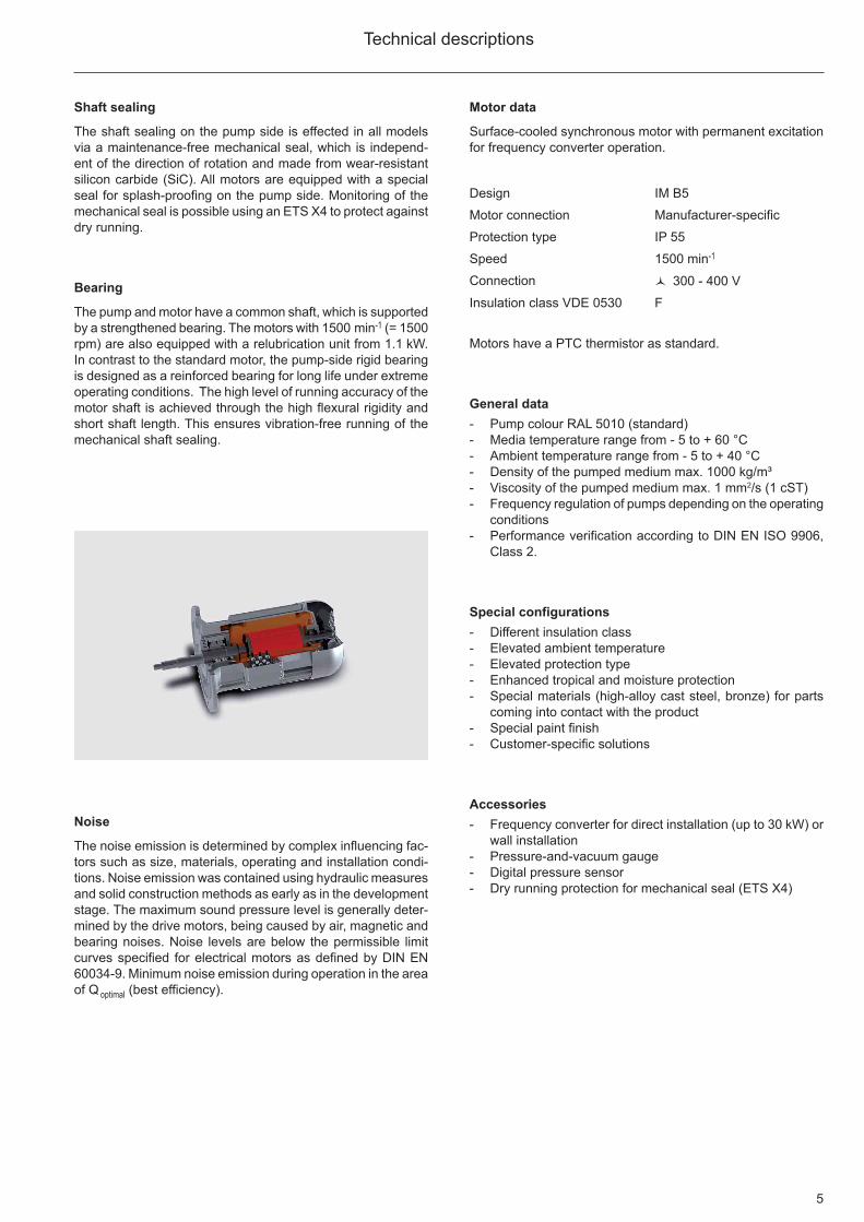
Bearing
The pump and motor have a common shaft, which is supported by a strengthened bearing. The motors with 1500 min-1 (= 1500 rpm) are also equipped with a relubrication unit from 1.1 kW. In contrast to the standard motor, the pump-side rigid bearing is designed as a reinforced bearing for long life under extreme operating conditions. The high level of running accuracy of the motor shaft is achieved through the high flexural rigidity and short shaft length. This ensures vibration-free running of the mechanical shaft sealing.
Motor data
Surface-cooled synchronous motor with permanent excitation for frequency converter operation.
Design IM B5
Motor connection Manufacturer-specific
Protection type IP 55
Speed 1500 min-1
Connection 3 300 - 400 V
Insulation class VDE 0530 F
Motors have a PTC thermistor as standard.
General data- Pump colour RAL 5010 (standard)- Media temperature range from - 5 to + 60 °C- Ambient temperature range from - 5 to + 40 °C- Density of the pumped medium max. 1000 kg/m³- Viscosity of the pumped medium max. 1 mm2/s (1 cST)- Frequency regulation of pumps depending on the operating
conditions- Performance verification according to DIN EN ISO 9906,
Class 2.
Special configurations- Different insulation class- Elevated ambient temperature- Elevated protection type- Enhanced tropical and moisture protection- Special materials (high-alloy cast steel, bronze) for parts
coming into contact with the product- Special paint fi nish- Customer-specifi c solutions
Accessories- Frequency converter for direct installation (up to 30 kW) or
wall installation- Pressure-and-vacuum gauge- Digital pressure sensor- Dry running protection for mechanical seal (ETS X4)
Noise
The noise emission is determined by complex influencing fac-tors such as size, materials, operating and installation condi-tions. Noise emission was contained using hydraulic measures and solid construction methods as early as in the development stage. The maximum sound pressure level is generally deter-mined by the drive motors, being caused by air, magnetic and bearing noises. Noise levels are below the permissible limit curves specified for electrical motors as defined by DIN EN 60034-9. Minimum noise emission during operation in the area of Q optimal (best efficiency).
6
Model designation
Example:150-270/0304SPX-PM-W2-V
Nominal diameter pressure fl ange DN [mm]Design dimensionsHydraulic versionMotor rating P2 [kW]E.g.: 030 = 3.0 kWSpeed4 = 1500 min-1
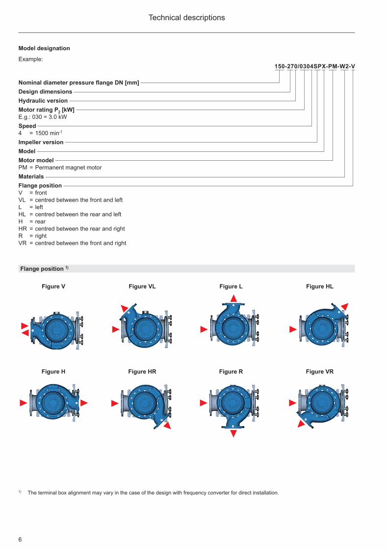
Impeller versionModelMotor modelPM = Permanent magnet motorMaterialsFlange positionV = frontVL = centred between the front and leftL = leftHL = centred between the rear and leftH = rearHR = centred between the rear and rightR = rightVR = centred between the front and right
Technical descriptions
Flange position 1)
Figure V Figure L
Figure VR
Figure VL Figure HL
Figure H Figure HR Figure R
1) The terminal box alignment may vary in the case of the design with frequency converter for direct installation.
7
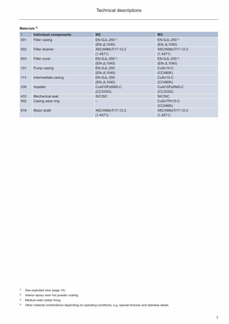
1) See exploded view (page 14)2) Interior epoxy resin hot powder coating3) Medium-side rubber lining4) Other material combinations depending on operating conditions, e.g. special bronzes and stainless steels.
Technical descriptions
Materials 4)
1) Individual components W2 W3001 Filter casing EN-GJL-250 2) EN-GJL-250 3)
(EN-JL1040) (EN-JL1040)002 Filter strainer X6CrNiMoTi17-12-2 X6CrNiMoTi17-12-2
(1.4571) (1.4571)003 Filter cover EN-GJL-250 3) EN-GJL-250 3)
(EN-JL1040) (EN-JL1040)101 Pump casing EN-GJL-250 CuSn10-C
(EN-JL1040) (CC480K)113 Intermediate casing EN-GJL-250 CuSn10-C
(EN-JL1040) (CC480K)230 Impeller CuAl10Fe5Ni5-C CuAl10Fe5Ni5-C
(CC333G) (CC333G)433 Mechanical seal SiC/SiC SiC/SiC502 Casing wear ring – CuSn7Pb15-C
(CC496K)819 Motor shaft X6CrNiMoTi17-12-2 X6CrNiMoTi17-12-2
(1.4571) (1.4571)

8
Overview
Tech
nica
l inf
orm
atio
n on
the
para
llel c
onne
ctio
n of
cen
trifu
gal p
umps
on
requ
est.
1500 min-1
H [m]
[ft]
01
52
05
01
00
15
0Q
[l/s]
10
01
00
01
50
02
00
0[U
S.g
pm
]
01
00
50
01
00
01
50
02
00
0[I
mp
.gp
m]
05
20
50
10
02
00
30
04
00
60
0Q
[m³/
h]
05
10
15
20
25
30
35
40
020
60
10
0
50
0
100-3
31/1
104
05
00
40-2
21/0
154
40
-221/0
114
150-2
70/0
304S
P
40
80
12
0
100-3
33/1
504
65-3
02/1
104
65-3
01/0
754
65-3
02/0
754
65
-27
0/0
55
4
65-2
71/0
404
50
-24
1/0
30
4
50
-24
1/0
22
4
65-2
70/0404
200-
270/
2204
200-
270/
1854
200-
270/
1504
200-
270/
1104
200-
250/
1504
200-
250/
1104
200-
250/
0754
200-
250/
0554
150-
250/
1104
150-
301/
1504
150-
301/
1854
150-
301/
2204
200-
331/
3004
200-
350/
3704
200-
350/
4504
200-
350/
5504
125-
252/
0404
125-
252/
0554
65-2
43/0
404
65-2
43/0
304
50-1
91/0154
50
-191/011
4
50-241/0154
80-2
55/0
304
80-2
55/0
554
80-2
11/0
154
80-2
41/0
224
100-3
33/1104
100-
211/
0404
80-2
41/0
404
80-2
41/0
304
100-2
01/0
224
125-3
31/2
204
125-
331/
1854
125-
270/
1504
100-
271/
0554
100-
211/
0304
125-
270/
1104
125-
270/
0754
100-271/0
754
100-241/0554
125-
271/
1104
100-
201/
0304
150-
250/
0754
150-
250/
0554
80-3
32/1
104
80-3
32/1
504
65
0
65-2
43/0
224
80-2
55/0
404
100-
241/
0754
125-
252/
0304
150-2
71/0
304S
P150-2
70/0
224S
P
25
00
9
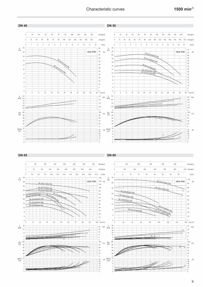
1500 min-1Characteristic curves
DN 40 DN 50
DN 65 DN 80
40X-PM
8
0
4
2
6
10
15
20
30
25
0
5
10
60
40
20
0
80
100
60
40
20
0
80
100
40-221/0114X-PM
H[m]
P[kW]
NPSH[m]
Eta[%]
[Imp.gpm]
[US.gpm]
Q [l/s]
0 4 8 12 16 20 24 28 32 36 40 44
0 15 30 45 60 75 90 105 120 135 150
0 1 2 3 4 5 6 7 8 9 10 11 12
0 15 30 45 60 75 90 105 120 135 150 165 180
6
4
2
0
12
10
8
16
14
18
20
0
20
35
40
45
55
50
60
65
25
30
15
5
10
2,4
2,0
1,6
1,2
0,8
0,4
0
3,2
2,4
0,8
1,6
0
40-221/0154X-PM
1
2
1
2
12
2
1
[ft]
Q [m /h]3
[ft]
[%]
[hp]
6
4
2
0
14
12
10
8
18
16
20
22
24
0
25
40
50
45
55
65
60
70
75
30
35
20
10
5
15
0 4 8 12 16 20 24 28 32 36 40 44 48
0 15 30 45 60 75 90 105 120 135 150 165
0 15 30 45 60 75 90 105 120 135 150 165 180 195 210
0 1 2 3 4 5 6 7 8 9 10 11 12 13
8
0
4
2
6
10
15
20
30
25
0
5
10
60
40
20
0
80
100
60
40
20
0
80
100
H[m]
P[kW]
NPSH[m]
Eta[%]
[Imp.gpm]
[US.gpm]
Q [l/s]
50-241/0304X-PM50-241/0224X-PM
50-241/0154X-PM50-191/0154X-PM50-191/0114X-PM
12
3
4 5
123
4
5
1 2
3
4
5
1 2
34 5
3,2
2,4
1,6
0,8
0
4,0
3,2
1,6
2,4
0
0,8
50X-PM
[ft]
Q [m /h]3
[ft]
[%]
[hp]
0 10 20 30 40 50 60 70 80 90 100
0 50 100 150 200 250 300 350
0 50 100 150 200 250 300 350 400
0 2,5 5,0 7,5 10,0 12,5 15,0 17,5 20,0 22,5 25,0 27,5
8
0
4
2
6
10
15
20
30
25
0
5
10
60
40
20
0
80
100
60
40
20
0
80
100
61
2
3
45
6
1 23
4
5
6
1 2 34 5
6
1 2
3
4 5
H[m]
P[kW]
NPSH[m]
Eta[%]
[Imp.gpm]
[US.gpm]
Q [l/s]
65-302/0754X-PM
7
7
7
65-270/0554X-PM65-243/0404X-PM
65-243/0304X-PM
65-243/0224X-PM
65X-PM
8
9
65-301/0754X-PM
65-302/1104X-PM
8
9
7
89
8 9
12
8
4
0
24
20
16
32
28
36
40
0
40
70
80
90
110
100
120
130
50
60
30
10
20
16
12
8
4
0
20
16
8
12
0
4
[ft]
Q [m /h]3
[ft]
[%]
[hp]
65-270/0404X-PM
65-271/0404X-PM
0 20 40 60 80 100 120 140 160
H[m]
P[kW]
NPSH[m]
Eta[%]
[Imp.gpm]
[US.gpm]
Q [l/s]
0 100 200 300 400 500
0 100 200 300 400 500 600 700
0 5 10 15 20 25 30 35 40
8
0
4
2
6
10
15
20
30
25
0
5
10
8
4
0
20
16
12
24
28
32
0
30
50
60
70
80
90
100
40
20
10
24
20
16
12
8
4
0
32
24
8
16
0
60
40
20
0
80
100
60
40
20
0
80
100
12
6
8
80-241/0154X-PM 80-241/0224X-PM
80-241/0304X-PM
80-241/0404X-PM
80-255/0304X-PM
80-255/0404X-PM
80-255/0554X-PM
80-332/1104X-PM
80-332/1504X-PM
3
4
7
9
1 2 34
5 6 7
8
9
5
4
4
5
1 6
3
7
7
8
8
9
9
80X-PM
2
5
[ft]
Q [m /h]3
[ft]
[%]
[hp]
321 6
10
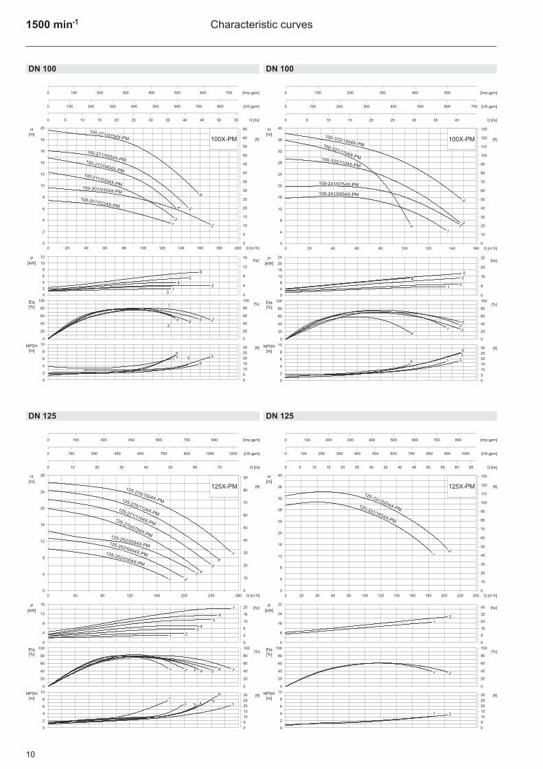
1500 min-1 Characteristic curves
DN 100 DN 100
DN 125 DN 125
4
1
0 20 40 60 80 100 120 140 160 180 200
0 100 200 300 400 500 600 700
0 100 200 300 400 500 600 700 800
0 5 10 15 20 25 30 35 40 45 50 55
8
0
4
2
6
10
15
20
30
25
0
5
10
60
40
20
0
80
100
60
40
20
0
80
100
5
2
6
4
1
5
2
3
4
1
5 2
3
4
1 5 2
16
12
4
8
0
12
10
8
6
4
2
0
3
H[m]
P[kW]
NPSH[m]
Eta[%]
[Imp.gpm]
[US.gpm]
Q [l/s]
100-271/0554X-PM100-211/0404X-PM
100-211/0304X-PM100-201/0304X-PM
100-201/0224X-PM
6
6
6
3
6
4
2
0
12
10
8
16
14
18
20
0
20
35
40
45
55
50
60
65
25
30
15
5
10
100X-PM
[ft]
Q [m /h]3
[ft]
[%]
[hp]
100-271/0754X-PM
1
0 20 40 60 80 100 120 140 160
0 100 200 300 400 500
0 100 200 300 400 500 600 700
0 5 10 15 20 25 30 35 40
8
0
4
2
6
10
15
20
30
25
0
5
10
60
40
20
0
80
100
60
40
20
0
80
100
21
21
21
H[m]
P[kW]
NPSH[m]
Eta[%]
[Imp.gpm]
[US.gpm]
Q [l/s]
100-333/1504X-PM
3
4
34
3
4
4 3
100-331/1104X-PM
100-241/0554X-PM
5
5
5
5
12
8
4
0
24
20
16
32
28
36
40
0
40
70
80
90
110
100
120
130
50
60
30
10
20
24
20
16
12
8
4
0
32
24
8
16
0
100X-PM
[ft]
Q [m /h]3
[ft]
[%]
[hp]
100-333/1104X-PM
100-241/0754X-PM
2
2
3
125-270/1504X-PM
4
5
6
0 40 80 120 160 200 240 280
0 150 300 450 600 750 900
0 150 300 450 600 750 900 1050 1200
0 10 20 30 40 50 60 70
8
0
4
2
6
10
15
20
30
25
0
5
10
8
4
0
16
12
20
24
28
0
30
60
70
90
80
40
50
20
10
60
40
20
0
80
100
60
40
20
0
80
100
7
23
4
5
6
7
2 3 4 5 6 7
2 3 45
6
7
H[m]
P[kW]
NPSH[m]
Eta[%]
[Imp.gpm]
[US.gpm]
Q [l/s]
125-270/1104X-PM125-271/1104X-PM
125-270/0754X-PM125-252/0554X-PM125-252/0404X-PM125-252/0304X-PM
1
1
1
1
125X-PM
[ft]
Q [m /h]3
[ft]
[%]
[hp]16
12
8
4
0
20
16
8
12
0
4
1
2
125-331/2204X-PM
0 20 40 60 80 100 120 140 160 180 200 220 240
0 100 200 300 400 500 600 700 800
0 100 200 300 400 500 600 700 800 900 1000
0 5 10 15 20 25 30 35 40 45 50 55 60 65
8
0
4
2
6
10
15
20
30
25
0
5
10
60
40
20
0
80
100
60
40
20
0
80
100
1
2
1 2
1 2
32
24
16
8
0
40
32
16
24
0
8
H[m]
P[kW]
NPSH[m]
Eta[%]
[Imp.gpm]
[US.gpm]
Q [l/s]
125-331/1854X-PM
12
8
4
0
24
20
16
32
28
36
40
0
40
70
80
90
110
100
120
130
50
60
30
10
20
125X-PM
[ft]
Q [m /h]3
[ft]
[%]
[hp]

11
1500 min-1Characteristic curves
DN 150 DN 150
DN 200 DN 200
0 80 160 240 320 400 480 560
0 300 600 900 1200 1500 1800
0 300 600 900 1200 1500 1800 2100 2400
0 20 40 60 80 100 120 140
8
0
4
2
6
10
15
20
30
25
0
5
10
60
40
20
0
80
100
60
40
20
0
80
100
8
4
0
20
16
12
24
28
32
0
30
50
60
70
80
90
100
40
20
101
2
3
4
5
6
12
3
4
5
6
1 2 3
45 6
12
3
4
5 6
H[m]
P[kW]
NPSH[m]
Eta[%]
[Imp.gpm]
[US.gpm]
Q [l/s]
150X-PM
[ft]
Q [m /h]3
[ft]
[%]
[hp]
150-250/0554X-PM
150-250/0754X-PM
150-250/1104X-PM
150-301/1504X-PM
150-301/1854X-PM
150-301/2204X-PM
24
20
16
12
8
4
0
32
24
8
16
0
12
150-270/0304SPX-PM
3
0 40 80 120 160 200 240 280
0 150 300 450 600 750 900
0 150 300 450 600 750 900 1050 1200
0 10 20 30 40 50 60 70
8
0
4
2
6
10
15
20
30
25
0
5
10
60
40
20
0
80
100
60
40
20
0
80
100
1
23
12
3
1 23
H[m]
P[kW]
NPSH[m]
Eta[%]
[Imp.gpm]
[US.gpm]
Q [l/s]
150-271/0304SPX-PM
150-270/0224SPX-PM
2
1
0
5
4
3
6
7
8
0
8
12
16
20
24
4
SP150X-PM
[ft]
Q [m /h]3
[ft]
[%]
[hp]4
3
2
1
0
5
4
2
3
0
1
2 3 5
6 7
0 80 160 240 320 400 480 560 640
0 300 600 900 1200 1500 1800 2100
0 300 600 900 1200 1500 1800 2100 2400 2700
0 20 40 60 80 100 120 140 160
8
0
4
2
6
10
15
20
30
25
0
5
10
60
40
20
0
80
100
60
40
20
0
80
100
200-250/1504X-PM
23
56
78
23
5 6 7 8
2 35 6 7
8
8
H[m]
P[kW]
NPSH[m]
Eta[%]
[Imp.gpm]
[US.gpm]
Q [l/s]
6
4
2
0
14
12
10
8
18
16
20
22
24
0
25
40
50
45
55
65
60
70
75
30
35
20
10
5
15
200-270/2204X-PM
200-270/1854X-PM
200-250/1104X-PM
200-270/1504X-PM
200-250/0754X-PM
24
20
16
12
8
4
0
32
24
8
16
0
1
1
1
1
200-250/0554X-PM
200-270/1104X-PM
4
4
4
4
200X-PM
[ft]
Q [m /h]3
[ft]
[%]
[hp]
1
3
2
4
0 80 160 240 320 400 480 560 640
0 300 600 900 1200 1500 1800 2100
0 300 600 900 1200 1500 1800 2100 2400 2700
0 20 40 60 80 100 120 140 160
8
0
4
2
6
10
15
20
30
25
0
5
10
60
40
20
0
80
100
60
40
20
0
80
100
200-350/5504X-PM
1
3
2
4
1
324
132 4
H[m]
P[kW]
NPSH[m]
Eta[%]
[Imp.gpm]
[US.gpm]
Q [l/s]
200-350/4504X-PM200-350/3704X-PM200-331/3004X-PM
12
8
4
0
28
24
20
16
36
32
40
44
48
0
50
80
100
90
110
130
120
140
150
60
70
40
20
10
30
200X-PM
[ft]
Q [m /h]3
[ft]
[%]
[hp]60
50
40
30
20
10
0
80
60
20
40
0
12
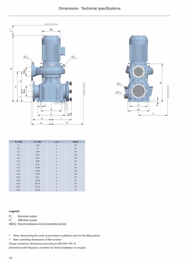
Dimensions · Technical specifi cations
1) When dismounting the motor ensure there is suffi cient room for the lifting device.2) Main controlling dimensions of fi lter strainerFlange connection dimensions according to DIN 2501 PN 10Dimensions with frequency converter for direct installation on request.
x1)
t
øk
DN
2D
N1
h
H
al
G /12
G1 /12
G /34
u
q
n
f 2)
id
e
p
m
s
G /3
8
~30
w
P2 [ kW] P1 [ kW] 3/5 dB(A)
1,1 1,29 3 52
1,5 1,7 3 55
2,2 2,49 3 55
3,0 3,35 3 55
4,0 4,44 3 56
5,5 5,98 3 61
7,5 8,15 3 63
11,0 11,89 3 63
15,0 16,29 3 65
18,5 19,94 3 65
22,0 23,4 3 67
30,0 31,85 3 67
37,0 39,19 3 70
45,0 47,47 3 70
55,0 57,89 3 71
Legend:
P2: Nominal outputP1: Affective powerdB(A): Sound pressure level (complete pump)

13
P2 [ kW] P1 [ kW] 3/5 dB(A)
7.5 8.3 3 63
Dimensions · Technical specifi cations
1) When dismounting the motor ensure there is suffi cient room for the lifting device.2) Total weight of the pumpFlange connection dimensions according to DIN 2501 PN 10Dimensions with frequency converter for direct installation on request.
Model DN2 DN1 H a d e f h i ø k l m n p q s t min. u w x min.
2)
[kg]40-221/0114X-PM 40 100 705 225 200 200 660 345 240 157 120 234 297 205 225 21 260 17 439 300 8740-221/0154X-PM 40 100 730 225 200 200 660 345 240 176 120 234 297 205 225 21 260 17 439 300 9050-191/0114X-PM 50 100 710 225 200 200 660 345 240 157 120 234 297 205 225 21 260 17 445 300 8550-191/0154X-PM 50 100 740 225 200 200 660 345 240 176 120 234 297 205 225 21 260 17 445 300 8850-241/0154X-PM 50 100 725 225 200 220 660 345 240 176 120 234 297 205 225 21 260 17 433 300 9250-241/0224X-PM 50 100 750 225 200 220 660 345 240 177 120 234 297 205 225 21 260 17 433 300 10150-241/0304X-PM 50 100 760 225 200 220 660 345 240 196 120 234 297 205 225 21 260 17 443 300 11165-243/0224X-PM 65 100 755 225 200 230 660 345 240 177 120 234 297 205 225 21 260 17 435 300 10465-243/0304X-PM 65 100 765 225 200 230 660 345 240 196 120 234 297 205 225 21 260 17 445 300 11365-243/0404X-PM 65 100 825 225 200 230 660 345 240 196 120 234 297 205 225 21 260 17 445 300 12065-270/0404X-PM 65 100 820 225 200 240 660 345 240 196 120 234 297 205 225 21 260 17 443 300 12165-271/0404X-PM 65 100 820 225 200 240 660 345 240 196 120 234 297 205 225 21 260 17 443 300 12165-270/0554X-PM 65 100 850 225 200 230 660 345 240 220 120 234 297 205 225 21 260 17 443 300 13365-301/0754X-PM 65 100 875 245 200 270 660 365 240 258 120 234 297 205 225 21 260 17 446 300 15865-302/0754X-PM 65 100 895 230 200 270 660 350 240 258 120 234 297 205 225 21 260 17 466 300 17165-302/1104X-PM 65 100 975 230 200 270 660 350 240 260 120 234 297 205 225 21 260 17 462 300 19480-241/0154X-PM 80 150 805 270 260 250 800 420 291 176 150 300 380 260 290 27 340 18 512 300 13480-241/0224X-PM 80 150 830 270 260 250 800 420 291 177 150 300 380 260 290 27 340 18 511 300 14380-241/0304X-PM 80 150 835 270 260 250 800 420 291 196 150 300 380 260 290 27 340 18 516 300 15080-241/0404X-PM 80 150 895 270 260 250 800 420 291 196 150 300 380 260 290 27 340 18 516 300 15780-255/0304X-PM 80 150 840 276 260 271 800 426 291 196 150 300 380 260 290 27 340 18 524 300 15680-255/0404X-PM 80 150 900 276 260 271 800 426 291 196 150 300 380 260 290 27 340 18 524 300 16380-255/0554X-PM 80 150 930 276 260 271 800 426 291 220 150 300 380 260 290 27 340 18 524 300 17380-332/1104X-PM 80 150 1060 275 260 315 800 425 291 260 150 300 380 260 290 27 340 18 547 1) 22880-332/1504X-PM 80 150 1095 275 260 315 800 425 291 313 150 300 380 260 290 27 340 18 547 1) 257
100-201/0224X-PM 100 150 855 300 260 280 800 450 291 177 150 300 380 260 290 27 340 18 536 300 133100-201/0304X-PM 100 150 860 300 260 280 800 450 291 196 150 300 380 260 290 27 340 18 541 300 143100-211/0304X-PM 100 150 835 270 260 270 800 420 291 196 150 300 380 260 290 27 340 18 515 300 154100-211/0404X-PM 100 150 895 270 260 270 800 420 291 196 150 300 380 260 290 27 340 18 515 300 162100-241/0554X-PM 100 150 950 270 260 270 800 420 291 220 150 300 380 260 290 27 340 18 543 300 180100-241/0754X-PM 100 150 975 270 260 270 800 420 291 258 150 300 380 260 290 27 340 18 543 300 198100-271/0554X-PM 100 150 925 275 260 270 800 425 291 220 150 300 380 260 290 27 340 18 519 300 174100-271/0754X-PM 100 150 950 275 260 270 800 425 291 258 150 300 380 260 290 27 340 18 519 300 192100-331/1104X-PM 100 150 1060 290 260 270 800 440 291 260 150 300 380 260 290 27 340 18 550 1) 237100-333/1104X-PM 100 150 1060 290 260 290 800 440 291 260 150 300 380 260 290 27 340 18 550 1) 237100-333/1504X-PM 100 150 1100 290 260 290 800 440 291 313 150 300 380 260 290 27 340 18 550 1) 265125-252/0304X-PM 125 150 855 290 260 300 800 440 291 196 150 300 380 260 290 27 340 18 538 300 167125-252/0404X-PM 125 150 915 290 260 300 800 440 291 196 150 300 380 260 290 27 340 18 538 300 174125-252/0554X-PM 125 150 945 290 260 300 800 440 291 220 150 300 380 260 290 27 340 18 538 300 188125-270/0754X-PM 125 150 965 275 260 280 800 425 291 258 150 300 380 260 290 27 340 18 536 300 196125-270/1104X-PM 125 150 1060 275 260 280 800 425 291 260 150 300 380 260 290 27 340 18 549 1) 222125-271/1104X-PM 125 150 1060 275 260 280 800 425 291 260 150 300 380 260 290 27 340 18 549 1) 222125-270/1504X-PM 125 150 1100 275 260 280 800 425 291 313 150 300 380 260 290 27 340 18 549 1) 251125-331/1854X-PM 125 150 1225 325 260 370 800 475 291 315 150 300 380 260 290 27 340 18 625 1) 310125-331/2204X-PM 125 150 1250 325 260 370 800 475 291 350 150 300 380 260 290 27 340 18 625 1) 334150-250/0554X-PM 150 200 1025 335 310 330 920 515 340 220 180 360 457 320 350 32 340 20 615 300 235150-250/0754X-PM 150 200 1045 335 310 330 920 515 340 258 180 360 457 320 350 32 340 20 615 300 253150-250/1104X-PM 150 200 1140 335 310 330 920 515 340 260 180 360 457 320 350 32 340 20 628 1) 284150-270/0224SPX-PM 150 200 1030 426 310 300 920 606 340 177 180 360 457 320 350 32 340 20 711 300 204150-270/0304SPX-PM 150 200 1035 426 310 300 920 606 340 196 180 360 457 320 350 32 340 20 716 300 213150-271/0304SPX-PM 150 200 1035 426 310 300 920 606 340 196 180 360 457 320 350 32 340 20 716 300 209150-301/1504X-PM 150 200 1185 350 310 330 920 530 340 313 180 360 457 320 350 32 340 20 637 1) 315150-301/1854X-PM 150 200 1285 350 310 370 920 530 340 315 180 360 457 320 350 32 340 20 685 1) 351150-301/2204X-PM 150 200 1310 350 310 370 920 530 340 350 180 360 457 320 350 32 340 20 685 1) 384200-250/0554X-PM 200 250 1130 394 350 350 1030 609 383 220 215 430 535 380 410 32 360 20 724 300 307200-250/0754X-PM 200 250 1155 394 350 350 1030 609 383 258 215 430 535 380 410 32 360 20 724 300 325200-250/1104X-PM 200 250 1250 394 350 350 1030 609 383 260 215 430 535 380 410 32 360 20 737 1) 354200-250/1504X-PM 200 250 1285 394 350 350 1030 609 383 313 215 430 535 380 410 32 360 20 737 1) 383200-270/1104X-PM 200 250 1265 398 350 370 1030 613 383 260 215 430 535 380 410 32 360 20 755 1) 372200-270/1504X-PM 200 250 1305 398 350 370 1030 613 383 313 215 430 535 380 410 32 360 20 755 1) 399200-270/1854X-PM 200 250 1385 398 350 370 1030 613 383 315 215 430 535 380 410 32 360 20 785 1) 427200-270/2204X-PM 200 250 1410 398 350 370 1030 613 383 350 215 430 535 380 410 32 360 20 785 1) 452200-331/3004X-PM 200 250 1430 402 350 400 1030 617 383 400 215 430 535 380 410 32 360 20 782 1) 531200-350/3704X-PM 200 250 1455 407 350 410 1030 622 383 392 215 430 535 380 410 32 360 20 796 1) 605200-350/4504X-PM 200 250 1495 407 350 410 1030 622 383 392 215 430 535 380 410 32 360 20 796 1) 636200-350/5504X-PM 200 250 1475 407 350 410 1030 622 383 438 215 430 535 380 410 32 360 20 796 1) 711
Exa
mpl
e (ta
ble
page
12)
14
320.1
320.2
423
819
006
1711.)
554
400.1
101
412.1
001
005.2
802
940
113
433
230
5022.)
920
412.2
903
002
003
004
832831
005.1
400.2
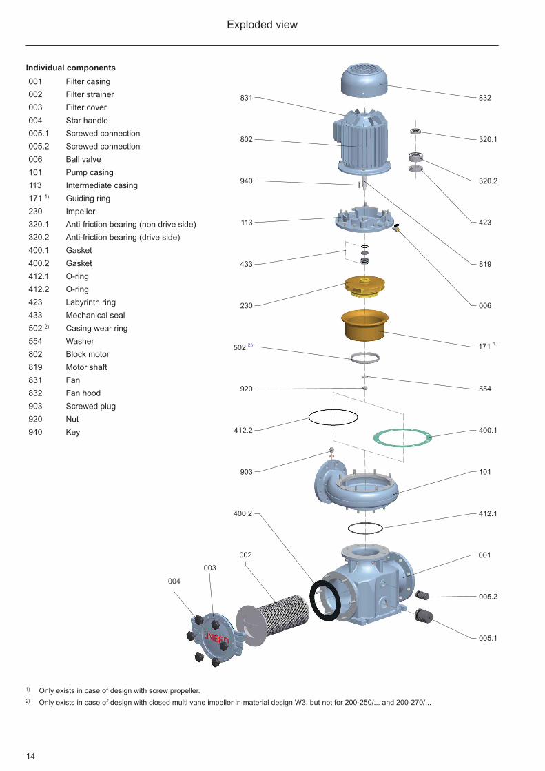
Exploded view
Individual components001 Filter casing002 Filter strainer003 Filter cover 004 Star handle005.1 Screwed connection005.2 Screwed connection006 Ball valve101 Pump casing113 Intermediate casing171 1) Guiding ring230 Impeller320.1 Anti-friction bearing (non drive side)320.2 Anti-friction bearing (drive side)400.1 Gasket400.2 Gasket412.1 O-ring412.2 O-ring423 Labyrinth ring433 Mechanical seal502 2) Casing wear ring554 Washer802 Block motor819 Motor shaft831 Fan832 Fan hood903 Screwed plug920 Nut940 Key
1) Only exists in case of design with screw propeller.2) Only exists in case of design with closed multi vane impeller in material design W3, but not for 200-250/... and 200-270/...

15
PM motors
Highest efficiency: Advantages in comparison with asynchronous motors
In comparison with the asynchronous motors mainly used in swimming pool technology, the synchronous motor (PM motor) has clear advantages. This is because asynchronous motors have a lower efficiency than synchronous motors due to rotor slippage. The smaller the asynchronous motor, the higher the losses and thus the worse the efficiency. In these applications, PM motors are the optimum alternative: with their efficiencies, they are already groups above motors according to IE3, which means that they achieve even better efficiencies than required for IE3 according to the IEC code.
Motor technology with energy efficiency IE3
The new PM motor (synchronous motor) technology offers three decisive advantages:• More performance due to very high effi ciencies• Fewer operating costs due to high energy savings• Fewer CO2 emissions due to lower power consumption
PM motors already achieve the efficiencies now that will be required by law starting in 2015. They have a constant motor efficiency above IE3 (premium efficiency class).
200180160140120100806040200
12
11
10
9
8
7
6
5
4
3
2
1
0
H
[m]
200180160140120100806040200
6
5
4
3
2
1
0
P
[kW]1
5
10
15
20
25
30
35
0Q [m /h]
3
[Imp.gpm]
[US.gpm]
Q [l/s]
0 100 200 300 400 500 600 700
0 100 200 300 400 500 600 700 800
0 5 10 15 20 25 30 35 40 45 50 55
2
4
6
8
0
[ft]
[hp]
Efficiency of asynchronous motor
Efficiency of PM motor
Calculation of the efficiency at Q = 120m³/hP = U * I * cosφ * √3Pasynchronous = 401.9 x 6.83 x 0.79 x 1.73 = 3.75 kWPPM = 330.0 x 5.73 x 1.0 x 1.73 = 3.27 kWSavings = 0.48 kW = 12.8%
Comparison of the efficiencies
The pump curve shown in the diagram with 3 kW drive output compares the electrical power consumption (efficiency) of the PM motor with an asynchronous motor. The PM motor has a considerably lower power consumption.
IEC energy class IEC code EFF codeSuper premium efficiency IE4 Premium efficiency IE3 High efficiency IE2 EFF1Standard efficiency IE1 EFF2Below standard efficiency - EFF3
Comparison of old EFF code and new IEC code
Efficiency comparison of IE1 - IE2 - IE3 for 4-pole motors
P-XS 01 GB
We reserve the right to make changes in line with technical further developments!
J.H. Hoffmann GmbH & Co. KG | Littau 3-5 | DE-35745 Herborn℡ +49 (0) 27 72 / 933-0 | +49 (0) 27 72 / [email protected] | www.herborner-pumpen.de
Related Documents