SLAC-PROPOSAL-E-166(bis) Revision Date: June 27, 2003 Undulator-Based Production of Polarized Positrons A Proposal for the 50-GeV Beam in the FFTB Gideon Alexander DE,TA , Perry Anthony SL , Vinod Bharadwaj SL , Yuri K. Batygin SL , Ties Behnke DE,SL , Steve Berridge UT , Gary R. Bower SL , William Bugg UT , Roger Carr SL , Eugene Chudakov JL , James E. Clendenin SL , Franz-Josef Decker SL , Yuri Efremenko UT , Ted Fieguth SL , Klaus Fl¨ ottmann DE , Masafumi Fukuda TO , Vahagn Gharibyan DE , Thomas Handler UT , Tachishige Hirose WA , Richard H. Iverson SL , Yuri Kamychkov UT , Hermann Kolanoski HU , Thomas Lohse HU , Changguo Lu PR , Kirk T. McDonald P R, 1 Norbert Meyners DE , Robert Michaels JL , Alexandre A. Mikhailichenko CO , Klaus M¨ onig DE , Gudrid Moortgat-Pick DU , Michael Olson SL , Tsunehiko Omori KE , Dimitry Onoprienko BR , Nikolaj Pavel HU , Rainer Pitthan SL , Milind Purohit SC , Louis Rinolfi CE , K.-Peter Sch¨ uler DE , John C. Sheppard SL, 1 Stefan Spanier UT , Achim Stahl DE , Zen M. Szalata SL , James Turner SL , Dieter Walz SL , Achim Weidemann SC , John Weisend SL BR Brunel University, Uxbridge, Middlesex UB8 3PH, United Kingdom CE CERN, CH-1211 Geneva 23, Switzerland CO Cornell University, Ithaca, NY 14853 DE DESY, D-22603 Hamburg, Germany DU University of Durham, Durham DH1 3HP, United Kingdom JL Thomas Jefferson National Accelerator Facility, Newport News, VA 23606 HU Humboldt University, Berlin, Germany KE KEK, Tsukuba-shi, Ibaraki, Japan PR Joseph Henry Laboratory, Princeton University, Princeton, NJ 08544 SC University of South Carolina, Columbia, SC 29208 SL SLAC, Stanford, CA 94309 TA University of Tel Aviv, Tel Aviv 69978, Israel TO Tokyo Metropolitan University, Hachioji-shi, Tokyo, Japan UT University of Tennessee, Knoxville, TN 37996 WA Waseda University, 389-5 Shimooyamada-machi,Machida,Tokyo 194-0202 Updates of this living document are available here: http://www-project.slac.stanford.edu/lc/local/PolarizedPositrons/E-166bis.pdf The E-166 Project Website: http://www-project.slac.stanford.edu/lc/local/PolarizedPositrons/index.htm 1 Co-Spokesperson

Welcome message from author
This document is posted to help you gain knowledge. Please leave a comment to let me know what you think about it! Share it to your friends and learn new things together.
Transcript

SLAC-PROPOSAL-E-166(bis)Revision Date: June 27, 2003
Undulator-Based Productionof Polarized Positrons
A Proposal for the 50-GeV Beam in the FFTB
Gideon AlexanderDE,TA, Perry AnthonySL, Vinod BharadwajSL, Yuri K. BatyginSL,Ties BehnkeDE,SL, Steve BerridgeUT , Gary R. BowerSL, William BuggUT , Roger CarrSL,Eugene ChudakovJL, James E. ClendeninSL, Franz-Josef DeckerSL, Yuri EfremenkoUT ,
Ted FieguthSL, Klaus FlottmannDE, Masafumi FukudaTO, Vahagn GharibyanDE ,Thomas HandlerUT , Tachishige HiroseWA, Richard H. IversonSL, Yuri KamychkovUT ,Hermann KolanoskiHU , Thomas LohseHU , Changguo LuPR, Kirk T. McDonaldPR, 1
Norbert MeynersDE , Robert MichaelsJL, Alexandre A. MikhailichenkoCO , Klaus MonigDE,Gudrid Moortgat-PickDU , Michael OlsonSL, Tsunehiko OmoriKE, Dimitry OnoprienkoBR,
Nikolaj PavelHU , Rainer PitthanSL, Milind PurohitSC , Louis RinolfiCE ,K.-Peter SchulerDE , John C. SheppardSL, 1 Stefan SpanierUT , Achim StahlDE ,
Zen M. SzalataSL, James TurnerSL, Dieter WalzSL, Achim WeidemannSC , John WeisendSL
BR Brunel University, Uxbridge, Middlesex UB8 3PH, United KingdomCE CERN, CH-1211 Geneva 23, Switzerland
CO Cornell University, Ithaca, NY 14853DE DESY, D-22603 Hamburg, Germany
DU University of Durham, Durham DH1 3HP, United KingdomJL Thomas Jefferson National Accelerator Facility, Newport News, VA 23606
HU Humboldt University, Berlin, GermanyKE KEK, Tsukuba-shi, Ibaraki, Japan
PR Joseph Henry Laboratory, Princeton University, Princeton, NJ 08544SC University of South Carolina, Columbia, SC 29208
SL SLAC, Stanford, CA 94309TA University of Tel Aviv, Tel Aviv 69978, Israel
TO Tokyo Metropolitan University, Hachioji-shi, Tokyo, JapanUT University of Tennessee, Knoxville, TN 37996
WA Waseda University, 389-5 Shimooyamada-machi,Machida,Tokyo 194-0202
Updates of this living document are available here:http://www-project.slac.stanford.edu/lc/local/PolarizedPositrons/E-166bis.pdf
The E-166 Project Website:http://www-project.slac.stanford.edu/lc/local/PolarizedPositrons/index.htm
1 Co-Spokesperson

Executive Summary
The full exploitation of the physics potential of future linear colliders such as the JLC,NLC, and TESLA will require the development of polarized positron beams. In the proposedscheme of Balakin and Mikhailichenko [1] a helical undulator is employed to generate photonsof several MeV with circular polarization which are then converted in a relatively thin targetto generate longitudinally polarized positrons.
This experiment, E-166, proposes to test this scheme to determine whether such a tech-nique can produce polarized positron beams of sufficient quality for use in future linearcolliders. The experiment will install a meter-long, short-period, pulsed helical undulatorin the Final Focus Test Beam (FFTB) at SLAC. A low-emittance 50-GeV electron beampassing through this undulator will generate circularly polarized photons with energies upto 10 MeV. These polarized photons are then converted to polarized positrons via pair pro-duction in thin targets. Titanium and tungsten targets, which are both candidates for usein linear colliders, will be tested. The experiment will measure the flux and polarization ofthe undulator photons, and the spectrum and polarization of the positrons produced in theconversion target, and compare the measurement results to simulations. Thus the proposedexperiment directly tests for the first time the validity of the simulation programs used forthe physics of polarized pair production in finite matter, in particular the effects of multiplescattering on polarization.
Successful comparison of the experimental results to the simulations will lead to greaterconfidence in the proposed designs of polarized positrons sources for the next generation oflinear colliders.
This experiment requests six-weeks of time in the FFTB beam line: three weeks forinstallation and setup and three weeks of beam for data taking. A 50-GeV beam with abouttwice the SLC emittance at a repetition rate of 30 Hz is required.
i

Contents
1 Introduction 21.1 Undulator Based Production of Polarized Positrons . . . . . . . . . . . . . . 21.2 The Need for a Demonstration Experiment . . . . . . . . . . . . . . . . . . . 31.3 Comparison with Positron Sources for Linear Colliders . . . . . . . . . . . . 41.4 Physics Opportunities at a Linear Collider with Polarized Electrons and Po-
larized Positrons . . . . . . . . . . . . . . . . . . . . . . . . . . . . . . . . . 41.4.1 Effective Polarization . . . . . . . . . . . . . . . . . . . . . . . . . . . 61.4.2 Standard Model Physics . . . . . . . . . . . . . . . . . . . . . . . . . 71.4.3 Enhancement of Effective Luminosity . . . . . . . . . . . . . . . . . . 71.4.4 Physics beyond the Standard Model . . . . . . . . . . . . . . . . . . . 81.4.5 Transversely Polarized Beams . . . . . . . . . . . . . . . . . . . . . . 91.4.6 Precision Measurement of Beam Polarization . . . . . . . . . . . . . . 101.4.7 Summary of the Physics Potential . . . . . . . . . . . . . . . . . . . . 11
2 Principles of the Experiment 122.1 Overview . . . . . . . . . . . . . . . . . . . . . . . . . . . . . . . . . . . . . . 122.2 Production of Circularly Polarized γ-Rays . . . . . . . . . . . . . . . . . . . 12
2.2.1 Overview . . . . . . . . . . . . . . . . . . . . . . . . . . . . . . . . . 122.2.2 Details . . . . . . . . . . . . . . . . . . . . . . . . . . . . . . . . . . . 13
2.3 Production of Polarized Positrons . . . . . . . . . . . . . . . . . . . . . . . . 142.3.1 Overview . . . . . . . . . . . . . . . . . . . . . . . . . . . . . . . . . 142.3.2 Details . . . . . . . . . . . . . . . . . . . . . . . . . . . . . . . . . . . 15
2.4 Polarimetry of MeV γ-Rays . . . . . . . . . . . . . . . . . . . . . . . . . . . 182.5 Polarimetry of MeV Positrons . . . . . . . . . . . . . . . . . . . . . . . . . . 21
3 The Apparatus 243.1 Overview . . . . . . . . . . . . . . . . . . . . . . . . . . . . . . . . . . . . . . 243.2 The Beamline . . . . . . . . . . . . . . . . . . . . . . . . . . . . . . . . . . . 26
3.2.1 Layout . . . . . . . . . . . . . . . . . . . . . . . . . . . . . . . . . . . 263.2.2 Beam Parameters . . . . . . . . . . . . . . . . . . . . . . . . . . . . . 263.2.3 Synchrotron Radiation Background . . . . . . . . . . . . . . . . . . . 283.2.4 Collimators . . . . . . . . . . . . . . . . . . . . . . . . . . . . . . . . 283.2.5 Alignment . . . . . . . . . . . . . . . . . . . . . . . . . . . . . . . . . 293.2.6 Instrumentation . . . . . . . . . . . . . . . . . . . . . . . . . . . . . . 30
3.3 The Undulator . . . . . . . . . . . . . . . . . . . . . . . . . . . . . . . . . . 303.4 The Photon Polarimeter . . . . . . . . . . . . . . . . . . . . . . . . . . . . . 31
3.4.1 Magnetized Iron Absorber . . . . . . . . . . . . . . . . . . . . . . . . 333.4.2 Silicon-Tungsten Calorimeter . . . . . . . . . . . . . . . . . . . . . . 333.4.3 Aerogel Flux Counters . . . . . . . . . . . . . . . . . . . . . . . . . . 34
3.5 The Positron Production Target . . . . . . . . . . . . . . . . . . . . . . . . . 353.6 The Positron Polarimeter . . . . . . . . . . . . . . . . . . . . . . . . . . . . . 36
3.6.1 The Positron Transport System . . . . . . . . . . . . . . . . . . . . . 373.6.2 The Magnetized Iron Absorber . . . . . . . . . . . . . . . . . . . . . 38
ii

3.6.3 The CsI Calorimeter . . . . . . . . . . . . . . . . . . . . . . . . . . . 403.7 Data-Acquisition System . . . . . . . . . . . . . . . . . . . . . . . . . . . . . 41
4 Measurements of Photon and Positron Polarization 444.1 Undulator Photons . . . . . . . . . . . . . . . . . . . . . . . . . . . . . . . . 44
4.1.1 Flux . . . . . . . . . . . . . . . . . . . . . . . . . . . . . . . . . . . . 444.1.2 Polarization . . . . . . . . . . . . . . . . . . . . . . . . . . . . . . . . 44
4.2 Positrons . . . . . . . . . . . . . . . . . . . . . . . . . . . . . . . . . . . . . . 474.2.1 Flux . . . . . . . . . . . . . . . . . . . . . . . . . . . . . . . . . . . . 474.2.2 Polarization . . . . . . . . . . . . . . . . . . . . . . . . . . . . . . . . 48
5 Experimental Measurements and Setup 515.1 Overview . . . . . . . . . . . . . . . . . . . . . . . . . . . . . . . . . . . . . . 515.2 Experimental Measurements . . . . . . . . . . . . . . . . . . . . . . . . . . . 515.3 Experiment Setup . . . . . . . . . . . . . . . . . . . . . . . . . . . . . . . . . 52
5.3.1 Status of Required Beamline Equipment . . . . . . . . . . . . . . . . 525.3.2 Installation and Check Out Requirements . . . . . . . . . . . . . . . 535.3.3 Beam Tuning and System Integration . . . . . . . . . . . . . . . . . . 57
6 References 58
iii

List of Figures
1 Conceptual scheme for undulator-based production of polarized positrons. . 32 Conceptual layout of the experiment. . . . . . . . . . . . . . . . . . . . . . 43 Effective polarization vs.positron polarization. . . . . . . . . . . . . . . . . . 74 Selectron pair production with longitudinally polarized beams. . . . . . . . 95 Search for extra dimension with transversely polarized beams. . . . . . . . . 106 Photon number spectrum and helicity spectrum. . . . . . . . . . . . . . . . 147 Photon number spectrum and helicity spectrum. . . . . . . . . . . . . . . . 158 Longitudinal polarization of positrons from a circularly polarized photon. . 169 Longitudinal polarization of positrons from a thin target. . . . . . . . . . . 1610 Positron energy and polarization. . . . . . . . . . . . . . . . . . . . . . . . . 1711 Positron energy spectrum for Ti targets. . . . . . . . . . . . . . . . . . . . . 1812 Concept of transmission polarimetry. . . . . . . . . . . . . . . . . . . . . . . 1813 Compton scattering cross sections. . . . . . . . . . . . . . . . . . . . . . . . 1914 Photon attenuation length and transmission in iron. . . . . . . . . . . . . . 2015 Figure of merit for transmission polarimetry. . . . . . . . . . . . . . . . . . 2116 Polarization transfer from positrons to photons. . . . . . . . . . . . . . . . . 2217 Analyzing power for positron polarimetry. . . . . . . . . . . . . . . . . . . . 2318 Conceptual layout of the experiment. . . . . . . . . . . . . . . . . . . . . . 2419 Conceptual layout of positron production and polarimetry. . . . . . . . . . . 2520 Prototype of the helical undulator. . . . . . . . . . . . . . . . . . . . . . . . 3121 Schematic representation of the undulator with pulsing circuit. . . . . . . . 3122 Mechanical drawing of the undulator. . . . . . . . . . . . . . . . . . . . . . 3223 Photon transmission probability through 15 cm of iron . . . . . . . . . . . . 3324 The silicon tungsten calorimeter. . . . . . . . . . . . . . . . . . . . . . . . . 3425 The aerogel flux counter. . . . . . . . . . . . . . . . . . . . . . . . . . . . . 3526 Layout of the positron polarimeter. . . . . . . . . . . . . . . . . . . . . . . . 3727 Momentum acceptance of the positron polarimeter. . . . . . . . . . . . . . . 3828 Photons in the upstream part of the positron polarimeter. . . . . . . . . . . 3929 Positrons in the upstream part of the positron polarimeter. . . . . . . . . . 3930 Probability that a positron reaches the reconversion target. . . . . . . . . . 4031 Probability that a background photon reaches the CsI array. . . . . . . . . . 4032 Field map along the axis of the magnetized iron absorber. . . . . . . . . . . 4133 CsI readout electronics. . . . . . . . . . . . . . . . . . . . . . . . . . . . . . 4234 Photon spectra after the iron absorber. . . . . . . . . . . . . . . . . . . . . 4535 Analyzing power vs. reconversion target thickness. . . . . . . . . . . . . . . 4836 Analyzing power vs. momentum acceptance. . . . . . . . . . . . . . . . . . . 49
List of Tables
1 TESLA, NLC, E-166 polarized positron parameters. . . . . . . . . . . . . . 52 Effective polarization. . . . . . . . . . . . . . . . . . . . . . . . . . . . . . . 63 Scaling factors for WW and ZZ production. . . . . . . . . . . . . . . . . . 8
iv

4 Fraction of colliding particles for different beam polarizations. . . . . . . . . 85 E-166 beam parameters. . . . . . . . . . . . . . . . . . . . . . . . . . . . . . 266 E-166 photon beam parameters. . . . . . . . . . . . . . . . . . . . . . . . . 277 Photon flux from the helical undulator. . . . . . . . . . . . . . . . . . . . . 298 Parameters of the helical undulator system. . . . . . . . . . . . . . . . . . . 329 Positron yields from Ti and W-Re targets. . . . . . . . . . . . . . . . . . . . 3610 Parameters of the positron polarimeter. . . . . . . . . . . . . . . . . . . . . 3711 Data-acquisition system. . . . . . . . . . . . . . . . . . . . . . . . . . . . . 4312 Photon polarization measurements using the aerogel detector. . . . . . . . . 4713 Simulation results: positron energy scan. . . . . . . . . . . . . . . . . . . . 5014 E-166 beam parameter request. . . . . . . . . . . . . . . . . . . . . . . . . . 5115 Status of E-166 beamline equipment. . . . . . . . . . . . . . . . . . . . . . . 5416 Photon and positron polarimetry devices and detectors. . . . . . . . . . . . 5517 Detector installation and test plan. . . . . . . . . . . . . . . . . . . . . . . . 56
1

1 Introduction
The full exploitation of the physics potential of future linear colliders such as the JLC,NLC, and TESLA will require the development of polarized positron beams.
In the proposed scheme of Balakin and Mikhailichenko [1] a helical undulator is employedto generate photons of several MeV with circular polarization which are then converted in arelatively thin target to generate longitudinally polarized positrons.
To advance progress in this field, this experiment, E-166, proposes to test this schemeto determine whether such a technique can produce polarized positron beams of sufficientquality for use in future Linear Colliders. The experiment will install a 1-meter-long, short-period (λu = 2.4 mm, K = 0.17), pulsed helical undulator in the Final Focus Test Beam(FFTB) at SLAC. A low-emittance 50-GeV electron beam passing through this undulatorwill generate circularly polarized photons with energies up to a cutoff energy of about 10MeV. These polarized photons are then converted to polarized positrons via pair productionin thin targets.
This section describes the concept of polarized positron production, the need for exper-imental verification, and some of the more important physics justifications for the need forpolarized positrons in Linear Colliders.
1.1 Undulator Based Production of Polarized Positrons
A polarized positron source for a Linear Collider was first proposed by Balakin andMikhaili-chenko in 1979 in the framework of the VLEPP project [1]. The concept, schemat-ically sketched in Fig. 1, sends the high energy (≥ 150 GeV) electron beam of a LinearCollider through a (∼ 200 m-long) helical undulator to produce circularly polarized photonswith energies of about 11 MeV.1 While the electrons are further accelerated and broughtinto collision after passing through the undulator, the photons are converted in a thin targetinto electron-positron pairs. Here the polarization state of the photons is transferred to thepositrons and electrons (see below for details). Only the on-axis photons of the helical un-dulator radiation are completely circularly polarized; the degree of polarization is decreasingwith increasing emission angle. Hence, the polarization of the photons and of the generatedpositrons can be increased at the expense of the total number of positrons by collimation.The positrons are captured behind the target similarly to the case of a conventional positronsource [2, 3], and fed into a linac.
This undulator-based positron source concept offers the additional advantage that theheat load on the target is less than that of a conventional source, and so the former is verywell suited for the production of high intensity positron beams [4]. An undulator-basedpolarized positron sources can in principle be realized independently of the linac technology,i.e., independently of the details of the required pulse structure, because the number ofproduced positrons scales with the number of the electrons in the drive linac, and the pulse
1Alternatively, the undulator could be placed in the electron beam beyond the e+e− interaction point,using the “spent” electron beam. The beam quality of the disrupted electron beam is, however, poor dueto the strong beam-beam interaction (beamstrahlung). Moreover, the electron beam quality, and hence thepositron production efficiency, depend on the details of the collision (offsets etc.), which makes this optioneven more problematic.
2

Figure 1: Conceptual scheme for undulator-based production of polarizedpositrons.
structure of the electrons is directly copied to that of the positrons. In this sense it is anoption for all Linear Collider projects.
A related approach for the production of polarized positrons is to create circularly po-larized photons by means of Compton backscattering of laser light off a high-intensity elec-tron beam [5, 6, 7]. Undulator radiation can be thought of as Compton backscattering ofthe virtual photons of the undulator, and hence the photon spectrum and the polarizationcharacteristics of Compton backscattered photons are very similar to those of undulatorradiation. The requirements for the pulsed laser system to implement positron productionare extremely demanding, so the use of the electron beam plus undulator offers significanttechnical advantages compared to Compton backscattering of real photons.
1.2 The Need for a Demonstration Experiment
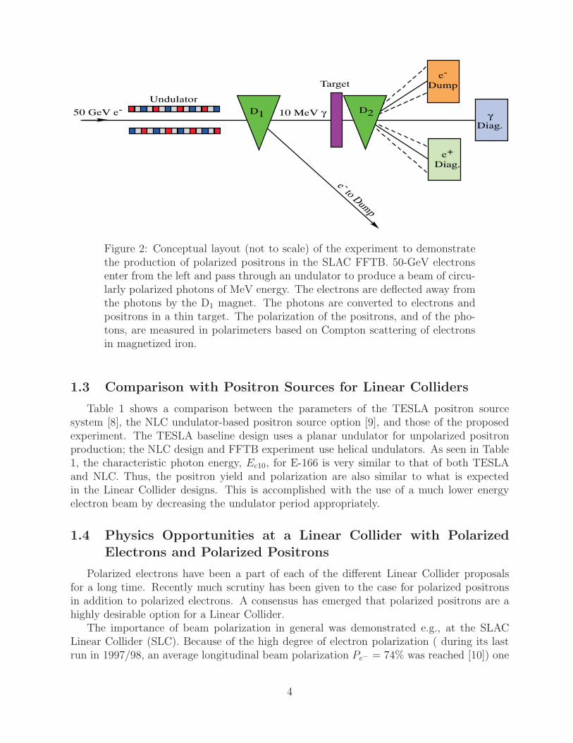
The aim of the proposed experiment E-166 is to test the fundamental process of polar-ization transfer in an electromagnetic cascade. For this, a simplified version of the schemeshown in Fig. 1 will be used, in which a 50-GeV electron beam passes through a 1-m-longundulator as shown in Fig. 2. The resulting photon beam of MeV energy is converted topositrons (and electrons) in a thin target, after which the polarization of the positrons (andphotons) is analyzed.
While the basic cross sections for the QED processes relevant to polarization transferwere derived in the late 1950’s, experimental verification of the polarization development inan electromagnetic cascade is still missing. From this point of view, the proposed experimenthas some general scientific aspects in addition to its importance for Linear Colliders.
Each approximation in the modeling of electromagnetic cascades seems to be well justifiedin itself, but the complexity of polarization transfer in cascades makes the comparison withan experiment desirable, so that the decision whether a Linear Collider should be built withor without a polarized positron source can be based on solid grounds. The achievable pre-cision of the proposed transmission polarimetry of 5-10% is sufficient for this purpose. Thisexperiment, however, will not address detailed systems issues related to polarized positronproduction for a Collider, such as capture efficiency, target thermal hydrodynamics, radia-tion damage in the target, or an undulator prototype suitable for use at a Linear Collider;such issues are well within the scope of R&D by a Linear Collider project that chooses toimplement a polarized positron source based on a helical undulator.
3
e - to Dump
D1
Undulator
50 GeV e-
e-
Dump
γDiag.
e+
Diag.
D2
Target
10 MeV γ
Figure 2: Conceptual layout (not to scale) of the experiment to demonstratethe production of polarized positrons in the SLAC FFTB. 50-GeV electronsenter from the left and pass through an undulator to produce a beam of circu-larly polarized photons of MeV energy. The electrons are deflected away fromthe photons by the D1 magnet. The photons are converted to electrons andpositrons in a thin target. The polarization of the positrons, and of the pho-tons, are measured in polarimeters based on Compton scattering of electronsin magnetized iron.
1.3 Comparison with Positron Sources for Linear Colliders
Table 1 shows a comparison between the parameters of the TESLA positron sourcesystem [8], the NLC undulator-based positron source option [9], and those of the proposedexperiment. The TESLA baseline design uses a planar undulator for unpolarized positronproduction; the NLC design and FFTB experiment use helical undulators. As seen in Table1, the characteristic photon energy, Ec10, for E-166 is very similar to that of both TESLAand NLC. Thus, the positron yield and polarization are also similar to what is expectedin the Linear Collider designs. This is accomplished with the use of a much lower energyelectron beam by decreasing the undulator period appropriately.
1.4 Physics Opportunities at a Linear Collider with Polarized
Electrons and Polarized Positrons
Polarized electrons have been a part of each of the different Linear Collider proposalsfor a long time. Recently much scrutiny has been given to the case for polarized positronsin addition to polarized electrons. A consensus has emerged that polarized positrons are ahighly desirable option for a Linear Collider.
The importance of beam polarization in general was demonstrated e.g., at the SLACLinear Collider (SLC). Because of the high degree of electron polarization ( during its lastrun in 1997/98, an average longitudinal beam polarization Pe− = 74% was reached [10]) one
4

Table 1: Parameters of polarized positrons beams at TESLA, NLC and thepresent experiment.
Parameter Units TESLA∗ NLC FFTB
Beam energy Ee GeV 150-250 150 50
Ne/bunch – 3 × 10¹⁰ 8 × 10⁹ 1 × 10¹⁰
Nbunch/pulse – 2820 190 1
Pulses/s Hz 5 120 30
Undulator type – planar helical helical
Undulator strength K – 1 1 0.17
Undulator period λu cm 1.4 1.0 0.24
1st Harmonic cutoff, Ec10 Mev 9-25 11 9.6
dNγ/dL photons/m/e− 1 2.6 0.37
Undulator length L m 135 132† 1
Target material – Ti-alloy Ti-alloy Ti-alloy
Target thickness rad. len.˙ 0.4 0.5 0.5
Yield e+/photon (%) 1-5 1.5‡ 0.5
Capture efficiency % 25 20 –
N+/pulse – 8.5 × 10¹² 1.5 × 10¹² 2 × 10⁷
N+/bunch – 3 × 10¹⁰ 8 × 10⁹ 2 × 10⁷
Polarization P + % – 40-70 40-70
∗ TESLA baseline design; TESLA polarized e+ parameters (undulator andpolarization) are the same as for the NLC.† A length of 132 m is required for a unity gain e− → e+ system. An undulatorlength of 200 m is under consideration in order to provide 50% overhead inpositron production.‡ Includes the effect of photon collimation at γθcut = 1.414.
5

of the world’s most precise measurements of the weak mixing angle at Z-pole energies wasperformed.
Having both beams polarized offers a number of advantages:
• Higher effective polarization.
• Increased signal to background in studies of Standard Model Physics.
• Enhancement of the effective luminosity.
• Precise analysis of many kinds of non-standard couplings.
• The option to use transversely polarized beams.
• Improved accuracy in measuring the polarization.
Details and examples of these effects are summarized in [13] and some key points are high-lighted here.
1.4.1 Effective Polarization
If both electron and positron polarization are available it is often useful to express thepolarization in terms of an effective polarization, Peff . As an example in the study of theleft-right asymmetry of s-channel vector particle exchange the effective polarization is definedas
Peff =Pe− − Pe+
1 − Pe−Pe+
. (1)
The error of the measurement of the left-right asymmetry scales roughly with 1 − Peff ,favoring a high effective polarization. The final error on the asymmetries measured willin many cases be limited by the error on the polarization. Having both beams polarizedsignificantly decreases the error on the effective polarization. This is illustrated in Fig. 3 andin Table 2.
Table 2: The effective polarization (1) for various e− and e+ polarizations.
Pe− = ±0.8 Pe− = ±0.9
Pe+ 0 ∓0.4 ∓0.6 0 ∓0.4 ∓0.6
|Peff | 0.80 0.91 0.95 0.90 0.95 0.97
1 − |Peff | 0.20 0.09 0.05 0.10 0.05 0.03
6

0 0.1 0.2 0.3 0.4 0.5 0.6 0.7 0.8 0.9 10.5
0.55
0.6
0.65
0.7
0.75
0.8
0.85
0.9
0.95
1
Pef
f
Positron Polarization
δPef
f/Pef
f for
δ P
/P=
1%
0 0.1 0.2 0.3 0.4 0.5 0.6 0.7 0.8 0.9 10
0.001
0.002
0.003
0.004
0.005
0.006
0.007
0.008
0.009
0.01
Figure 3: Solid curve: the effective polarization (1) at a Linear Collider as afunction of positron polarization, assuming an electron polarization of 90%.Dashed curve: the relative error in the effective polarization. From [11].
1.4.2 Standard Model Physics
Standard Model physics based on WW or ZZ production depends on the effective polar-ization of the two lepton beams. This can be used to either enhance or suppress the standardmodel processes (see Table 3 for some examples). As the dominant background processes formany new physics searches are WW and ZZ production, suppressing their contributions canenhance the search potential for new physics. A positron polarization of about Pe+ = 60%would double the suppression of the WW background. Similarly the background from singleW± production depends on the polarization of the positron beam, as well as on the electronbeam polarization.
1.4.3 Enhancement of Effective Luminosity
The chiral structure of Standard Model s-channel processes is given by (V−A) couplings.This means that only the (LR) and (RL) configurations of the initial e± contribute. Thefraction of colliding particles is therefore
1
2(1 − Pe−Pe+) ≡ Leff
L , (2)
which defines an effective luminosity Leff . If both beams are polarized this can be enhanced,as illustrated in Table 4.
7

Table 3: Scaling factors for WW and ZZ production. These mechanisms arethe dominant backgrounds for new physics searches, so smaller scaling factorscorrespond to better background suppression.
Pe− Pe+ e+e− → W+W− e+e− → ZZ
0 0 1.0 1.0
0.8 0 0.2 0.76
−0.8 0 1.8 1.25
0.8 −0.6 0.1 1.05
−0.8 0.6 2.85 1.91
Table 4: Fraction of colliding particles (Leff/L) and the effective polarization(Peff) for different beam polarization configurations, which are characteristicfor (V−A) processes in the s-channel [13].
Pe− Pe+ RL LR RR LL Peff Leff/L
0 0 0.25 0.25 0.25 0.25 0. 0.5
−1 0 0 0.5 0 0.5 −1 0.5
−0.8 0 0.05 0.45 0.05 0.45 −0.8 0.5
−0.8 +0.6 0.02 0.72 0.08 0.18 −0.95 0.74
1.4.4 Physics beyond the Standard Model
Beam polarization is of particular importance for the study of physics beyond the stan-dard model. Supersymmetry (SUSY) is a leading candidate for new physics. However, eventhe simplest version, the Minimal Supersymmetric Standard Model (MSSM), leads to 105new free parameters. If SUSY exists, one of the most important studies to be performed willbe the determination of the SUSY parameters in as model independent a way as possibleand to prove the underlying SUSY assumptions, e.g., that the SUSY particles carry the samequantum numbers (with the exception of the spin) as their Standard Model counterparts.
For example, SUSY transformations associate chiral (anti)fermions to scalars e−L,R ↔ e−L,R
but e+L,R ↔ e+
R,L. Both beams have to be polarized in order to prove these associations. [14].The process e+e− → e+e− occurs via γ and Z exchange in the s-channel and via neutralinoχ0
i exchange in the t-channel. The association can be directly tested only in the t-channel
8

and the use of polarized beams serves to separate out this channel. Fig. 4 shows an exampleof this where the selectron masses are close together, meL
= 200 GeV, meR= 190 GeV, so
that eL, eR decay via the same decay channels (in this example the other SUSY parametersare taken from the reference scenario SPS1a [15]). The e−L e+
R pair can be enhanced by theLL configuration of the initial beams. From the Figure, it is seen that just having theelectron beam polarized will not help. With Pe− = −80%, Pe+ = 0% the cross section forthe combinations σ(e−L e+
R) = 102 fb and σ(e−L e+L) = 108 fb are close together. This will
essentially not change even if Pe− = −100% were available.
0
50
100
150
200
250
-1 -0.5 0 0.5 1
sigm
a [fb
]
P(e+)
Figure 4: Separation of the selectron pair e−L e+R in e+e− → e−L,Re+
L,R with lon-gitudinally polarized beams in order to test the association of chiral quantumnumbers to scalar fermions in SUSY transformations [13].
However, if polarized positrons are available, a separation of the different combinationsmight be possible: Pe− = −80%, Pe+ = −40% result in σ(e−L e+
R) = 143 fb and σ(e−L e+L) =
66 fb. With Pe− = −80%, Pe+ = −60%, σ(e−L e+R) = 163 fb, σ(e−Re+
R) = 49 fb and σ(e−L e+L ) =
44 fb are obtained ( Fig. 4).For many SUSY analyzes other SUSY processes are the most important background.
Positron polarization can again be used to suppress the undesired process, as illustrated forselectron production in [16].
1.4.5 Transversely Polarized Beams
Recently, theoretical interest has increased into the physics opportunities transverselypolarized lepton beams offer [17]. The cross section involving transversely polarized leptonsis given by
σ = (1 − Pe+Pe−)σunpol + (P Le− − P L
e+)σLpol + P T
e−P Te+σT
pol. (3)
9

Access to the physics of the transverse cross section σTpol requires therefore that both beams
be polarized.It has been shown in [18] that transversely polarized beams project out W +
L W−L final
states, which are particularly important for studying the origin of electroweak symmetrybreaking. When studying the azimuthal asymmetry, which is very pronounced at highenergies reaching about 10% and peaks at larger angles, one has direct access to the LLmode of WW production without complicated final-state analyzes.
The azimuthal asymmetry is also a crucial observable when studying signals of extradimension in the process e+e− → f f [19]. With the use of transversely polarized beams it ispossible to probe spin-2 graviton exchange to about twice the sensitivity of “conventional”methods for analyzing contact interactions. In Fig. 5 the differential azimuthal asymmetrydistribution is shown whose asymmetric distribution is the signal for the graviton spin-2exchange.
Figure 5: Search for large extra dimensions in the ADD model in e+e− →f f with transversely polarized beams. Shown is the differential azimuthalasymmetry distribution whose asymmetric distribution is the signal for thegraviton spin-2 exchange. From [19].
1.4.6 Precision Measurement of Beam Polarization
A Linear Collider operating at energies around the Z0 pole is a very powerful instrumentto probe the precision structure of the standard model. Beam polarization contributes greatlyto the physics potential of this option. In order to exploit this physics potential a extremelyprecise knowledge of the degree of polarization is needed. At the moment no method existsto directly measure the beam polarization to well below 0.1%.
However if both the electron and the positron beams are polarized, the degree of polariza-tion can be measured from the events themselves. In this so-called extended Blondel scheme
10

the left-right asymmetry is directly measurable from observing counting rates in differentmachine configurations:
ALR =
√√√√(σ++ + σ+− − σ−+ − σ−−)(−σ++ + σ+− − σ−+ + σ−−)
(σ++ + σ+− + σ−+ + σ−−)(−σ++ + σ+− + σ−+ − σ−−). (4)
With this scheme an accuracy of the electroweak mixing angle of δ(sin2 θeff) = 0.00001and δ(MW ) = 6 MeV [20] seems possible.
1.4.7 Summary of the Physics Potential
Although already polarized electrons by themselves offer exciting physics opportunities,the addition of polarized positrons extends the physics reach of a Linear Collider signifi-cantly by increasing the level of control one has over the mixture of processes present in theevents observed. Using polarized e− and e+ beams simultaneously improves the power todetermine quantum numbers of new particles, provides higher sensitivity to non–standardmodel couplings and helps to reveal the structure of the underlying model. In many casesrates and purities of particular signals will be enhanced, even if only moderate (e.g. 40-60%) positron polarization can be achieved. Additional and often unique information canbe gained if not only longitudinally but also transversely polarized electrons and positronsare made available.
11

2 Principles of the Experiment
2.1 Overview
This section discusses the key physical processes of E-166. As discussed above, a high-energy electron beam in combination with a helical undulator is used to produce circularlypolarized photons. These photons pair-produce longitudinally polarized positrons in a thintarget. The polarization of the photons is determined through measurements of the relativephoton transmission through a magnetized iron absorber for positive and negative polarityof the iron magnetization. The polarization of the positrons is determined by first makingpolarized photons from the positrons in a reconversion target and subsequently measuringthe relative transmission through a magnetized iron absorber of the regenerated photons.
For E-166, each 50-GeV electron produces on average 0.4 photons. Each photon pairproduces at a rate of about 0.5% positrons/photon. The transmission efficiency of positronsto the reconversion target is about 2%. Reconversion occurs at a rate of about 1 photon perpositron. There is about a 0.25% transmission efficiency from the reconversion target intothe detector. Thus, for 1 × 10¹⁰ electrons per pulse, 4 × 10⁹ photons per pulse are made;resulting in 2 × 10⁷ positrons per pulse. Of these, 4 × 10⁵ positrons per pulse are incidenton the reconversion target and about 1× 10³ photons per pulse arrive at the detector in thepositron polarimeter. In the case of the photon polarimeter, the transmission through theiron absorber is about 1%, such that 4 × 10⁷ photons per pulse arrive at the detector.
2.2 Production of Circularly Polarized γ-Rays
2.2.1 Overview
Polarized positrons are to be produced by conversion of circularly polarized γ-rays ina thin target. The γ-rays are the result of backscattering of an electron beam of energyEe = γmc2 off the virtual photon of an undulator with period λu. To a first approximationthe energy of radiation at 0 is therefore
E0 ≈ 2γ2hc
λu= 24 [MeV]
(Ee/50[GeV])2
λu[mm]. (5)
The highest energy radiation takes on the polarization of the undulator field, so that a helicalundulator leads to circularly polarized γ-rays, the conversion of which leads to polarizedpositrons.
To create positrons, we need γ-rays of at least a few MeV, so we desire the highestpossible electron beam energy Ee, and the shortest possible undulator period λu. The highestpractical beam energy at SLAC is 50 GeV, in which case an undulator period λu of only 2.4mm is required to obtain 10-MeV γ-rays.
The aperture of the undulator must be smaller than its period, and will be of order 1 mm.Thus, the electron beam must have low emittance to pass through the undulator withoutscraping, and we are led to take advantage of the excellent beam quality of the SLAC FinalFocus Test Beam (FFTB).
12

The intensity of the γ-rays depends on the intensity of the virtual photons of the undu-lator, and hence on the square of its magnetic field strength. It is conventional to measurethe field strength of an undulator in terms of a dimensionless parameter K defined as,
K =2πeB0λu
mc2= 0.09B0[T]λu[mm], (6)
in which B0 is the peak, transverse magnetic field in the undulator. Then the rate ofundulator radiation is roughly 2αK2 per undulator period λu, where α is the fine-structureconstant. Because of the small undulator period required for use with a 50-GeV electronbeam, the highest practical value for K is about 0.2. In this case the number of γ-rays emittedper electron in a 1-m-long undulator of λu = 2.4 mm is 2(1/137)(0.2)2(1/0.0024) ≈ 0.2.
2.2.2 Details
Detailed descriptions of helical undulator radiation can be found in [21, 22, 23, 24, 25].Past applications of helical undulators include the generation of 200-eV circularly polarizedphotons to measure the polarization of the 650-MeV positron beam at the VEPP-2M storagering [26], and generation of 0.5-1 keV photons with nearly 100% circular polarization atSLAC’s SPEAR facility [27].
For small values of K, the number of photons dNγ/dL emitted per meter of an undulatoris
dNγ
dL=
4
3
πα
λu
K2
1 + K2=
30.6
λu[mm]
K2
1 + K2photons/m/e−. (7)
The photon number spectrum is relatively flat up to the maximum energy Ec10 of firstharmonic radiation,
Ec10 =2γ2hc/λu
1 + K2 + 2γλC/λu≈ 2γ2hc/λu
1 + K2≈ 24 [MeV]
(Ee/50[GeV])2
λu[mm](1 + K2), (8)
where λC = h/mc = 2.4×10⁻¹² m is the Compton wavelength of the electron. Small numbersof photons are emitted at higher energies, corresponding to higher multipole radiation by theelectrons. The detailed photon number spectrum is illustrated in Fig. 6(a) for the proposedexperimental parameters: Ee = 50 GeV, λu = 2.4 mm and K = 0.17.
There is a fixed kinematic relation between energy and angle of emission of the photonsdue to nth-order multipole radiation,
Eγ(n, θ) =nEc10
1 + (γθ)2/(1 + K2). (9)
As seen from (9), the upper half of the energy spectrum is emitted into a cone of angleθ =
√1 + K2/γ, where γ = Ee/mc2.
As previously mentioned, the polarization Pγ of the γ-rays produced at 0 is the same asthat of the undulator, but falls off for larger angles (which corresponds to lower energies).This behavior is illustrated in Fig. 6(b) for the proposed experimental parameters. Thepolarization of higher harmonic radiation approaches unity at the corresponding higher cutoffenergies, but the rates are very low there.
13

0 5 10 15 20 25 30 35 400
0.2
0.4
0.6
0.8
1
1.2
1.4
dN
(E)/
dE
(ar
b. u
nit
s)
Photon Number Spectrum, E1=9.62 MeV, K=0.17
Photon Energy (MeV)
0 5 10 15 20 25 30 35 40−1
−0.8
−0.6
−0.4
−0.2
0
0.2
0.4
0.6
0.8
1
Photon Energy (MeV)
Ph
oto
n P
ola
riza
tio
n, S
toke
s ξ 3
Photon Helicity to 4th order
Figure 6: (a) The photon number spectrum, intensity spectrum, of undulatorradiation, integrated over angle, for electron energy Ee = 50 GeV, undulatorperiod λu = 2.4 mm and undulator strength parameter K = 0.17. The peakenergy Ec10 of the first harmonic (dipole) radiation is 9.62 MeV. (b) Thepolarization Pγ of the undulator radiation as a function of energy.
If the photons are observed in a calorimeter, an appropriate measure of their effectivepolarization Pγ is the energy-weighted average polarization, obtained by multiplying thenumber of photons of energy E by E times the polarization at that energy. For the undulatorphotons considered here, the energy-weighted polarization is 49%.
The radiated power d2Uu/dLdt per meter of undulator by an electron beam is
d2Uu
dLdt= 2.32 × 10⁻⁴E2
e [GeV]K2
λ2u[mm]
ne[×1010]frep[Hz] W/m, (10)
in which ne is the number of electrons per pulse and frep is the pulse repetition rate.Figure 7 illustrates the γ-ray intensity spectrum (integrated over 0 < θ < π/2) and
angular distribution of undulator radiation for the proposed experimental parameters. Asmall contribution of quadrupole (2nd harmonic) and higher-order radiation can be seen forenergies of 10-20 MeV, which peaks at a nonzero angle of emission.
2.3 Production of Polarized Positrons
2.3.1 Overview
When a circularly polarized photon creates an electron-positron pair in a thin target, thepolarization state of the photon is transferred to the outgoing leptons according to the crosssections derived by Olsen and Maximon in 1959 [28]. Positrons with an energy close to theenergy of the incoming photons are 100% longitudinally polarized, while positrons with alower energy have a lower longitudinal polarization (see Fig. 8). At energies below 25% ofthe photon energy the sign of the positron polarization is opposite to that of the photon.
14

0 2 4 6 8 10 12 14 16 18 200
0.2
0.4
0.6
0.8
1
1.2
E (MeV)
dI(
E)/
dE
(ar
b. u
nit
s)
Kincaid eq 25, K=0.17, 2.4 mm, 50 GeV
1st Harmonic2nd Harmonic x10Sum of first 4 Harmonics
2nd x 10
0 0.2 0.4 0.6 0.8 1 1.2 1.4 1.6 1.8 20
0.1
0.2
0.3
0.4
0.5
0.6
0.7
0.8
0.9
1
γ θ
dI(
θ)/d
θ (a
rb. u
nit
s.)
Kincaid eq 24, K=0.17, 2.4 mm, 50 GeV
1st Harmonic2nd Harmonic x10Sum of first 4 Harmonics
2nd x 10
Figure 7: (a) The intensity spectrum of undulator radiation, integrated overangle, for a 50-GeV electron beam incident on an undulator with period λu =2.4 mm and strength parameter K = 0.17. (b) Intensity, integrated overenergy, vs. emission angle γθ.
The probability for the production of positrons is roughly independent of the fractionalenergy Ee+/Eγ in the pair-production process, so that positrons with all energies up to thephoton energy are produced (with initial polarization as shown in Fig. 8). However, even ina thin target, low-energy positrons are stopped due to the ionization loss (which rises sharplyfor energies below 1 MeV), while high-energy positrons loose a fraction of their energy dueto bremsstrahlung. The energy loss by bremsstrahlung is accompanied by a slight loss ofpolarization; however, the energy loss is stronger than the polarization loss. As a result, thelow-energy portion of the positron spectrum is repopulated with positrons from the higherenergy portion, and the polarization of positrons of a given energy is higher in targets of upto ≈ 0.5 radiation length than in an infinitely thin target [4], as shown in Fig. 9.
For targets thicker than about 0.5 radiation length the polarization decreases again.Hence, positrons are unpolarized in a conventional thick-target positron source even if theincoming electrons are polarized. (At very low yield polarized positrons may also be producedfrom polarized electrons using thin targets [29].)
2.3.2 Details
The basic processes of polarized electromagnetic cascades are well known, but under-standing of the interplay of all processes in a shower requires simulation with a Monte-Carlocode. To this end, the programs EGS4 [29, 30] and GEANT3 [31] have been modified toinclude effects of polarization.2
The polarized versions of these codes include the effects for pair production, bremsstrahlungand Compton scattering (with the exception of scattering asymmetries which are not consid-
2Improvements of the polarized Monte-Carlo codes are ongoing, in parallel to the preparation of theexperiment, in cooperation with colleagues from Byelorussia.
15
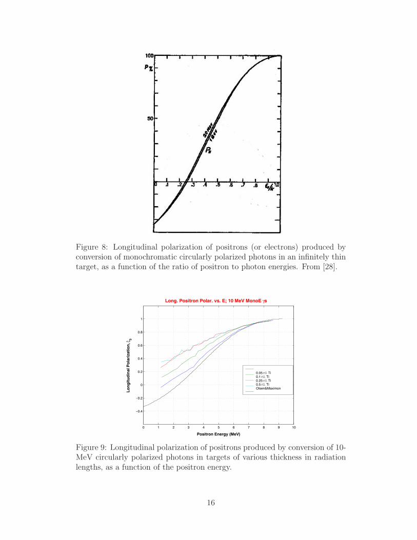
Figure 8: Longitudinal polarization of positrons (or electrons) produced byconversion of monochromatic circularly polarized photons in an infinitely thintarget, as a function of the ratio of positron to photon energies. From [28].
0 1 2 3 4 5 6 7 8 9 10
−0.4
−0.2
0
0.2
0.4
0.6
0.8
1
Long. Positron Polar. vs. E; 10 MeV MonoE γs
Positron Energy (MeV)
Lo
ng
itu
din
al P
ola
riza
tio
n, ξ
3
0.05 r.l. Ti0.1 r.l. Ti0.25 r.l. Ti0.5 r.l. TiOlsen&Maximon
Figure 9: Longitudinal polarization of positrons produced by conversion of 10-MeV circularly polarized photons in targets of various thickness in radiationlengths, as a function of the positron energy.
16

ered) [4]. The effects of other processes on the polarization, e.g., multiple Coulomb scattering,are not taken into account yet. A semi-classical approach is followed, by assigning an aver-age polarization to individual particles. The polarized cross sections of Olsen and Maximon[28] for pair production and bremsstrahlung and of Lipps and Tollhoek [32] for Comptonscattering are utilized. Various simplifications have been made in the simulations; for exam-ple, a 1/γ angular distribution of the outgoing particles is assumed for the bremsstrahlungand pair production cross sections by Olsen and Maximon, while EGS4 offers more accurateangular sampling at lower energies.
0 2 4 6 8 10 12 14 16 18 200
0.2
0.4
0.6
0.8
1
Ec1
=9.62 MeV, K=0.17, γθcut
=none
Lo
ng
itu
din
al P
ola
riza
tio
n ξ
3 an
d R
elat
ive
Nu
mb
er in
Bin
Positron Energy (MeV)0 1 2 3 4 5 6 7 8 9 10
−0.4
−0.2
0
0.2
0.4
0.6
0.8
1
1.2
Longitudinal Polarization vs. E; K=0.17, γθcut
= None
Positron Energy (MeV)
Lo
ng
itu
din
al P
ola
riza
tio
n, ξ
3
0.5 r.l. Ti
<ξ3(E)>
Figure 10: (a) Longitudinal polarization (solid curve) and energy spectrum(histogram) of positrons emitted from a 0.5-rad.-len.-thick Ti target that hasbeen irradiated with the photon energy and polarization spectra of Figs. 6and 7. (b) Positron longitudinal polarization as a function of energy. Thesolid lines in (a) and (b) are polarization averaged over a 0.5-MeV energyslice. The dip in the polarization at 9 MeV is due to the corresponding dip inphoton polarization at about 10 MeV as seen in Fig. 6(b).
Figure 10 shows the energy and polarization spectra of positrons produced in 0.5 rad.len. of Ti by photons from a helical undulator whose spectra are shown in Figs. 6a and 6b.The solid curve in each plot is the average polarization within a 0.5-MeV energy slice. Asexpected, the higher-energy positrons have generally higher polarization. The dip in thepolarization, at positron energies of about 9 MeV, is due to the corresponding dip in photonpolarization at 10 MeV as seen in Fig. 6(b). The composite polarization of the total sampleof positrons in Figures 10 is about 53%.
Figure 11 shows energy spectra of positrons for different lengths of a Ti convertor by un-dulator photons whose spectra are shown in Figs. 6 and 7. As the target thickness increases,the positron yield initially improves but decreases for a thickness of more than 0.25 rad. len.The energy spectra do not vary significantly with target thickness. For the conditions ofFig. 11, the yield is in the range of 0.3-0.5% positrons/photon for Ti thicknesses of 0.05-0.5rad. len.
The conversion efficiency from low-energy γ-rays to positrons in a thin target will be
17

0 5 10 15 200
50
100
150
200
250
300
Positron Energy (MeV)
∆N+/∆
E+
0.05 rl Ti
N+tot
=1719
Nγin = 500,000
0 5 10 15 200
50
100
150
200
250
300
Positron Energy (MeV)
∆N+/∆
E+
0.1 rl Ti
N+tot
=2329
Nγin = 500,000
0 5 10 15 200
50
100
150
200
250
300
Positron Energy (MeV)
∆N+/∆
E+
0.25 rl Ti
N+tot
=2549
Nγin = 500,000
0 5 10 15 200
50
100
150
200
250
300
Positron Energy (MeV)
∆N+/∆
E+
0.5 rl Ti
N+tot
=2274
Nγin = 500,000
E1=9.62 MeV, K=0.17, γθ
cut= none
Figure 11: Positron energy spectrum for Ti targets of thickness 0.05, 0.1, 0.25,and 0.5 rad. len. The target thickness, total number of emitted positrons, andtotal number of incident photons are indicated in each frame. The incidentphoton spectrum is shown in Fig. 6(a) and 7(a).
about 0.005, so the number of positrons produced per beam electron will be about 0.001.
2.4 Polarimetry of MeV γ-Rays
Measurements of the circular polarization of energetic photons are most commonly basedon the spin dependence of Compton scattering off atomic electrons [33, 34]. One can eitherobserve the scattered electrons and/or photons emerging from a thin, magnetized iron foil[35], or measure the transmission of unscattered photons through a thick, magnetized ironabsorber [36, 37, 38].
Figure 12: The concept of transmission polarimetry, in which the survival rateis measured for photons that pass through a magnetized iron absorber.
18

Because of its simplicity, we will use the latter technique, transmission polarimetry, whoseconcept is sketched in Fig. 12. In the first approximation, a single Compton scatter of aphoton removes it from the transmitted signal. The Compton scattering cross section canbe written
σ = σ0 + PγPeσP , (11)
where σ0 is the unpolarized cross section,
σ0 =πr2
0
k0
[(1 − 2
k0
− 2
k20
)ln(1 + 2k0) +
1
2+
4
k0
− 1
2(1 + 2k0)2
], (12)
Pγ is the net polarization of the photons, Pe is the net polarization of the atomic electrons(naively ±2/26 for Fe, but more accurately determined to be ±7.92% for iron at saturation),and σP is the polarized cross section given by
σP =2πr2
0
k0
[1 + 4k0 + 5k2
0
(1 + 2k0)2 − 1 + k0
2k0ln (1 + 2k0)
], (13)
where r0 = e2/mc2 is the classical electron radius and k0 = Eγ/mc2. The cross sections σ0
and σP for iron are shown in Fig 13, and the attenuation of photons in iron based on crosssection σ0 is illustrated in Fig. 14.
0 1 2 3 4 5 6 7 8 9 100
1
2
3
4
5
6
7
E (MeV)
To
tal c
ross−s
ecti
on
(b
arn
s/at
om
)
Total Photon Cross Section in Fe
0 1 2 3 4 5 6 7 8 9 10−0.025
−0.02
−0.015
−0.01
−0.005
0
E (MeV)
Po
lari
zed
cro
ss−s
ecti
on
(b
arn
s/el
ectr
on
)
Compton Cross Section in Fe
Figure 13: (a) The unpolarized photon cross section σ0 per iron atom , and(b) the polarized Compton cross section σP per electron in iron. From [39].
The transmission probability T±(L) for photons of helicity −Pγ through a piece of mag-netized iron whose length is L can be written as
T±(L) = e−nLσ = e−nLσ0e±nLPePγσP , (14)
where n is the number density of atoms in iron and the +(−) in T± applies if the electron spinin the iron is parallel (antiparallel) to the direction of the incident photons. The asymmetry
19

0 1 2 3 4 5 6 7 8 9 100
0.5
1
1.5
2
2.5
3
3.5
4
4.5
5
E (MeV)
Att
enu
atio
n L
eng
th in
Fe
(cm
)
Photon Attenuation Length in Fe
0 5 100
0.01
0.02
0.03
E (MeV)
Tra
nsm
issi
on
Transmission through 15 cm of Iron
Al
iP
Figure 14: (a) The attenuation length for MeV photon in iron, based on theunpolarized Compton cross section (8). (b) The transmission of unpolarizedphotons through 15 cm of iron.
δ in transmission of photons through the iron absorber when the sign of Pe is reversed,corresponding to a reversal of the magnetization of the iron, is
δ(L) =T+(L) − T−(L)
T+(L) + T−(L)= tanh(nLPePγσP ) ≈ nLPePγσP , (15)
This asymmetry is shown in Fig. 15(a) for various lengths of iron. The peak asymmetry isin the range of 1-6% for photon energies in the range of several MeV and for lengths of ironof 3-15 cm.
For small asymmetries such that the final form of eq. (15) holds, we can define an “ana-lyzing power” Aγ for transmission polarimetry according to
Aγ(L) ≡ δ(L)
PePγ≈ nLσP . (16)
Then, a measurement of the asymmetry δ, plus knowledge of the electron polarization Pe inthe magnetized iron, determines the photon polarization to be
Pγ =δ
PeAγ. (17)
The relative error on a measurement of the polarization varies inversely as the product ofthe analyzing power Aγ and the square root of the transmission factor T . We can thereforedefine a figure of merit for transmission polarimetry as A2
γT , where larger values are better.This figure of merit is shown in Fig. 15(b) for 7.5-MeV photons. We see that at this energyan 8-cm-long magnetized iron absorber is optimal.
20

0 5 10 15 20 25 30
−0.06
−0.04
−0.02
0
0.02
0.04
0.06
Photon Energy (MeV
δ
Methods of Exp. Phy. Vol 5, Part B, Eq. 2.5.672 ÷ 2
L0 = 3 cm Fe
L0 = 7 cm Fe
L0 = 10 cm Fe
L0 = 15 cm Fe
0 2 4 6 8 10 12 14 16 18 200
1
2x 10
−4
Length (cm)
Fig
ure
of
Mer
it
Figure of Merit
Figure 15: (a) The asymmetry δ defined in eq. (15) for transmission polarime-try of MeV photons in various lengths of iron. (b) The figure of merit A2
γT for7.5 MeV photons as a function of the length of a transmission iron polarimeter
2.5 Polarimetry of MeV Positrons
The polarization of the positrons can be analyzed by measurement of asymmetries inannihilation from [28, 40, 41, 42, 47], or Bhabha scattering off [43, 44, 45, 46, 47], po-larized electrons in a thin iron foil, and in Compton scattering off a circularly polarizedlaser [26]. Good precision can be obtained with a thin iron foil when a coincidence exper-iment is performed [47]. However, the simplest technique applicable to a high rate envi-ronment (where coincidences cannot be identified) is the method of transmission polarime-try in which the positrons are converted back into photons (either by annihilation [40, 41]or by bremsstrahlung [28, 48, 49]) and the latter are sent through a thick iron absorber[50, 51, 52, 53, 54, 55]. A measurement of the transmission asymmetry for magnetic fields(in the iron) parallel and antiparallel to the positron beam direction then allows one to inferthe polarization of the positrons.
The positrons can, in principle, become depolarized by atomic interactions prior to theemission of the photons that pass through the transmission polarimeter. However, this effectis at the level of a few percent for relativistic electrons [56, 57, 58], and is simulated in theEGS4 code that includes polarization.
The transfer of polarization from positrons to photons (“reconversion”) in a thin foil isillustrated in Fig. 16. The average polarization of the photons from a 10-MeV positron isonly 21% of that of the positron.
The photons that have been created by the positrons can then be analyzed in a trans-mission polarimeter as discussed in sec. 2.5. An asymmetry δ in the number of transmittedphotons is measured by reversing the polarization Pe− of the electrons in the iron absorber.
21

−2 0 2 4 6 8 10 120
0.2
0.4
0.6
0.8
1
Photon Energy (MeV)
Circ
ular
Pol
ariz
atio
n an
d N
umbe
r of
Pho
tons
/Bin
EGS4 and Olsen Maximon, Bremsstrahlung: 10 MeV e+, 0.5 mm W
1/E, "hand fit"
Pγ: O&M
EGS4
<P>=0.217
<P>=0.189
Figure 16: Solid curve: the polarization of photons generated by a 10-MeV positron incident on 0.5 mm of tungsten, as a function of photon en-ergy. Histogram: the energy spectrum the photons, which are mainly due tobremsstrahlung.
The polarization Pe+ of the parent positrons can then be inferred according to
Pe+ =δ
Pe−Ae+
, (18)
in terms of an analyzing power Ae+ that can be calculated in a simulation that combines theprocesses of polarization transfer from positron to photon and transmission of the photonsthrough the iron absorber. Because the reconverted photons have a nearly isotropic angulardistribution (due to the large multiple scattering of the parent positrons in the reconversiontarget), the computation of the analyzing power Ae+ is more complicated than for Aγ in thecase of transmission polarimetry of a collimated photon beam.
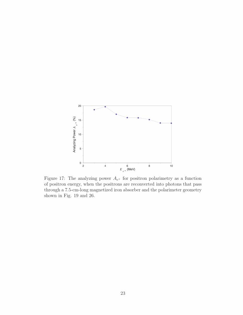
Figure 17 shows the analyzing power Ae+ for the example of a 7.5-cm-long iron absorberand the polarimeter geometry shown in Fig. 19 and 26.
22
108642Ee + (MeV)
20
15
10
5
0
Ana
lyzi
ngP
owerAe
+(%
)
Figure 17: The analyzing power Ae+ for positron polarimetry as a functionof positron energy, when the positrons are reconverted into photons that passthrough a 7.5-cm-long magnetized iron absorber and the polarimeter geometryshown in Fig. 19 and 26.
23

3 The Apparatus
3.1 Overview
The goal of the experiment is
• To measure the yield and polarization of the photons produced by passing an electronbeam through a helical undulator.
• To measure the yield and polarization of the positrons produced by conversion ofundulator photons in a thin target.
• To compare the results to simulations.
A schematic layout of the experiment is shown in Fig. 18 with emphasis on the particlebeams, while Fig. 19 shows the layout of the detectors to measure the flux and polarizationof the photons and positrons.
e - to Dump
D1
BPM3
Au
Undulator
e-
e-
Dump
γDiag.
e+
Diag.
At
D2
Target
BPM1 BPM2
WS
Toro
OTR PRt
HSB1 HSB2
Hcor
PRd
Figure 18: Conceptual layout (not to scale) of the experiment to demonstratethe production of polarized positrons in the SLAC FFTB. 50-GeV electronsenter from the left and are dumped using magnet D1 after traversing the undu-lator. The positron conversion target as well as the positron and photon diag-nostics are located 35 m downstream of the undulator. BPMi = beam-positionmonitor; HSBi =“hard” soft bend; OTR = optical-transition-radiation beam-profile monitor; Toro = beam-current toroid; WS = wire scanner; Ai = aper-ture limiting collimators; Hcor = horizontal steering magnet; D1 = FFTBprimary beam dump bend-magnet string; PRd = dumpline beam-profile mon-itor; PRt = e+ target beam-profile monitor; D2 = analyzing magnet.
The experiment uses a low-emittance, 50-GeV electron beam (sec. 3.2.2) in the SLACFinal Focus Test Beam (FFTB) plus a 1-meter-long, short-period (λu = 2.4-mm, K=0.17),pulsed helical undulator (sec. 3.3), to produce circularly polarized photons of energies upto 10 MeV. These polarized photons are then converted to polarized positrons through pairproduction in a Ti target which has a nominal thickness of 0.5 rad. len. The polarizations
24

Re-conversionTarget
Analyzer MagnetIron (7.5 cm long x 5 cm dia.) CsI - Calorimeter Detector
(behind lead shielding)
γ80
80
+
-
γγ
Reversible Magnetization
Pb Shielding
Positron Spectrometer
Flux Counter
End vacuum
Movable TargetTi, W 0.5 RL
To γ Dump
e+
e-
2.0
1.0
South Wall of FFTB
SiW Calorimeter
==> Collimation
Aerogel
Scale in Meters
Polarizedγs
Profile
Monitor
Spectrometer
3.01.0 2.51.50.5
0.5
Scale in Meters
Figure 19: Conceptual layout of the E–166 positron generation and photonand positron diagnostic systems.
of the photons and positrons are measured by the Compton transmission method using amagnetized iron absorber [37].
This experiment is a demonstration of undulator-based production of polarized positronsfor Linear Colliders at a scale of 1% in length and intensity:
• Photons are produced in the same energy range and polarization as in a Linear Collider;
• The same target thickness and material are used as in the Linear Collider;
• The polarization of the produced positrons is expected to be in the same range as ina Linear Collider.
• The simulation tools being used to model the experiment are the same as those be-ing used to design the polarized positron system for a Linear Collider: EGS4 [30]and GEANT3, both modified to include spin effects for polarized e+ production, andBEAMPATH [59] for collection and transport.
25
3.2 The Beamline
3.2.1 Layout
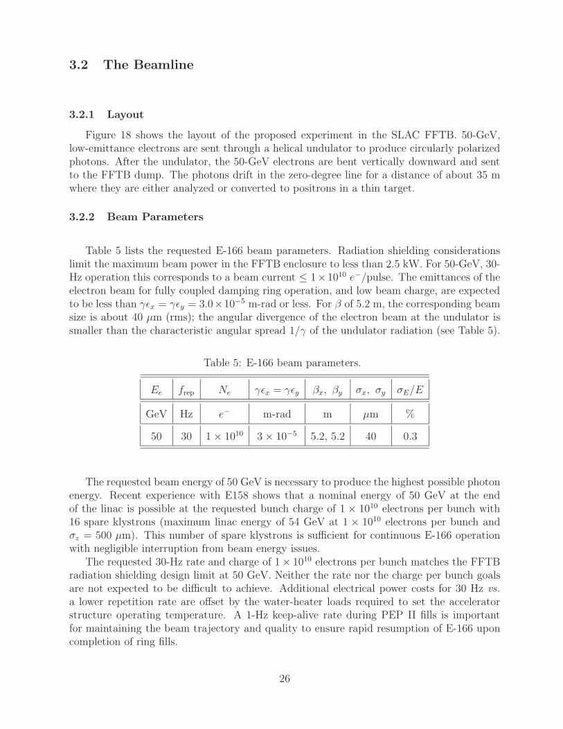
Figure 18 shows the layout of the proposed experiment in the SLAC FFTB. 50-GeV,low-emittance electrons are sent through a helical undulator to produce circularly polarizedphotons. After the undulator, the 50-GeV electrons are bent vertically downward and sentto the FFTB dump. The photons drift in the zero-degree line for a distance of about 35 mwhere they are either analyzed or converted to positrons in a thin target.
3.2.2 Beam Parameters
Table 5 lists the requested E-166 beam parameters. Radiation shielding considerationslimit the maximum beam power in the FFTB enclosure to less than 2.5 kW. For 50-GeV, 30-Hz operation this corresponds to a beam current ≤ 1×10¹⁰ e−/pulse. The emittances of theelectron beam for fully coupled damping ring operation, and low beam charge, are expectedto be less than γεx = γεy = 3.0×10⁻⁵ m-rad or less. For β of 5.2 m, the corresponding beamsize is about 40 µm (rms); the angular divergence of the electron beam at the undulator issmaller than the characteristic angular spread 1/γ of the undulator radiation (see Table 5).
Table 5: E-166 beam parameters.
Ee frep Ne γεx = γεy βx, βy σx, σy σE/E
GeV Hz e− m-rad m µm %
50 30 1 × 10¹⁰ 3 × 10⁻⁵ 5.2, 5.2 40 0.3
The requested beam energy of 50 GeV is necessary to produce the highest possible photonenergy. Recent experience with E158 shows that a nominal energy of 50 GeV at the endof the linac is possible at the requested bunch charge of 1 × 10¹⁰ electrons per bunch with16 spare klystrons (maximum linac energy of 54 GeV at 1 × 10¹⁰ electrons per bunch andσz = 500 µm). This number of spare klystrons is sufficient for continuous E-166 operationwith negligible interruption from beam energy issues.
The requested 30-Hz rate and charge of 1× 10¹⁰ electrons per bunch matches the FFTBradiation shielding design limit at 50 GeV. Neither the rate nor the charge per bunch goalsare not expected to be difficult to achieve. Additional electrical power costs for 30 Hz vs.a lower repetition rate are offset by the water-heater loads required to set the acceleratorstructure operating temperature. A 1-Hz keep-alive rate during PEP II fills is importantfor maintaining the beam trajectory and quality to ensure rapid resumption of E-166 uponcompletion of ring fills.
26

Table 6: E-166 photon beam parameters for an undulator strength parameterof K = 0.17 and distance from undulator to positron production target ofD = 35 m. σ′
eff = (1/γ2 + σ2x/D
2 + σ2x′)1/2 and σt = D/γeff .
Ee Ec10 γεx = γεy βx, βy σx, σy σx′ , σy′ 1/γ σ′eff σt
GeV MeV m-rad m µm µrad µrad µrad µm
50 9.62 2 × 10⁻⁵ 7.8, 7.8 40 5.1 10.2 11.5 402
50 9.62 4 × 10⁻⁵ 3.9, 3.9 40 10.2 10.2 14.5 507
47.5 8.68 2 × 10⁻⁵ 7.4, 7.4 40 5.4 10.8 12.1 423
47.5 8.68 4 × 10⁻⁵ 3.7, 3.7 40 10.8 10.8 15.3 534
A limiting constraint for E-166 is the 0.885 mm I.D. aperture of the undulator. Toprevent background generation due to beam interception, a beam size of 40 µm rms hasbeen adopted. This gives an undulator radius-to-beam size ratio of 11 σ. To achieve thisbeam size at 50 GeV, the β functions at IP1 must be set to the range of 7.8 m to 3.9 m forγε = 2-4 × 10⁻⁵ m-rad. The computer code DIMAD has been run to find magnet valuesfor β function at IP1 of 10 m and 2.5 m. The required magnet strengths are well withinthe magnet fabrication specifications and power supply operating ranges. An emittance atthe lower end of the expected tuning range, γε = 2 × 10⁻⁵ m-rad, is preferred for ease ofattaining the 40-µm rms beam size through the undulator.
A nominal value of γε = 3 × 10⁻⁵ m-rad is listed in Table 5. For the purpose of makingcomparisons, Table 6 summarizes the effects of the range of electron beam emittance on theE-166 photon beam energy Ec10 (first harmonic cutoff), angular divergence σ′
eff , and spotsize at the converter target σt at beam energies of 50 GeV and 47.5 GeV. In Table 6, the βfunction at IP1 is adjusted to keep a 40 µm electron beam size through the undulator.
An rms energy spread of σE/E ≤ 0.3% is a factor of 1.5-2 times larger than expectedfor the nominal bunch current with an rms bunch length of σz = 500 µm. This requirementon the energy spread is to limit the possibility of background generation in the FFTB dueto beam loss in regions of large dispersion. Little is known about the exact details ofbackgrounds due to transmission of large energy spreads through the FFTB, but it is prudentto keep the energy spread σE/E to as low a value as reasonable. Since the dispersion throughthe IP1 area is negligible, energy spread is not a concern in regards to the beam focusingnor potential background generation in the vicinity of the undulator.
E-164 was run in March, 2003 with a nominal beam current of 1 × 10¹⁰ electrons perbunch and measured emittances of γεx = 3.6 × 10⁻⁵ m-rad and γεy = 0.4 × 10⁻⁵ m-rad.Coupling in the damping ring would bring these emittances to γεx = γεy = 2× 10⁻⁵ m-rad.The energy spread of the E-164 beam was about 0.6% due to the 100-µm rms bunch length.A more typical bunch length of 500 µm rms would have an rms energy spread of less than0.2%. The longer bunch length results in increased transverse wakefields, which are not
27

expected to be problematic at the requested beam current of 1 × 10¹⁰ electrons per bunch.Multiple accesses to the FFTB housing will be required after the beam has been turned
on. These accesses are to install the undulator after initial beam setup and for detectorbackground shielding adjustments. During access, the 50-GeV beam is put onto the tuneupdump in the beam switchyard. Additionally, all power supplies and magnets remain energizedduring an FFTB entry. These two features, along with existing FFTB beam steering feedbacksystems, ensure rapid beam recovery after an access.
In summary, the requested beam and optics requirements are within the design speci-fications of the linac and FFTB. Furthermore, these criteria are less stringent than recent(March, 2003) operating experience.
3.2.3 Synchrotron Radiation Background
To avoid noise in the detectors from synchrotron radiation by electrons in upstreambeam transport magnets and in the dumpline magnets, a pair of soft bends is included inthe electron beamline just before and after the undulator (devices HSB1 and HSB2 in Fig. 18).These bends have the same polarity and give a vertical downward kick to the electron beam.This is similar to the geometry that was used successfully in experiment E-144 [60], albeitonly one set of “hard” soft bends are used for E-166 whereas E-144 used both “hard” softbends and “soft” soft bends. Table 7 lists expected photon parameters from the undulatorand bend magnets in the immediate vicinity of the experiment. The expected flux from theundulator is significantly higher in photon energy and number. In Table 7, hωc is the criticalenergy of the synchrotron radiation emitted by the bends; ∆L(3/γ) is the length of bendrequired to produce a 3/γ angular deflection in the beam; and the ∆Nγ and ∆PB are theradiated flux and power from the bends for the ∆L(3/γ) length segment of bend.
3.2.4 Collimators
Fig. 18 shows two aperture-limiting collimators for the experiment, Au, which protectsthe undulator from possible mis-steering of the primary electron beam, and At, which definesthe photon beam used to create the polarized positrons. These devices are 30-cm-long (∼ 20rad. len.) cylinders of copper with a 0.85-mm ID through hole for electron beam transmissionin Au, while collimator At has a 3-mm ID aperture for photon beam transmission.
Collimator Au is water cooled because of the possibility of primary beam interception;collimator At does not require water cooling.
Au is required to protect the undulator assembly from being hit head-on by the primaryelectron beam. With Au, failure of the soft bends could result in a glancing incidence of theelectron beam on the undulator. Preliminary calculations indicate that such interceptionwould not damage the undulator in a single shot; protection ion chambers located at theundulator will cause the beam to be turned off after detection of a single shot fault.
Collimator At is located just upstream of the undulator-photon conversion target, andserves to limit extraneous halo (both photons and charged particles) from entering into thedetector region of the experiment.
28

Table 7: Photon flux from the helical undulator. For comparison, parametersof the synchrotron radiation flux from the dump magnet D1 and the hard-softbends HSB1 and HSB2 are also listed.
Parameter Units Undulator D1 Bend HS Bend
Ee GeV 50 50 50
ne ×1010 e− 1 1 1
frep Hz 30 dc dc
Pe kW 2.4 2.4 2.4
B0 kG 7.58 4.45 0.660
K – 0.17 – –
dNγ/dL photons/m/e− 0.37 2.75 0.41
Ec10 (Ecrit) MeV 9.62 (0.739) (0.110)
Eavg MeV 4.81 0.228 0.034
dPu,B/dL mW/m 87 30 0.7
Lu (∆L(3/γ)) m 1 (0.01) (0.08)
∆Nγ photons/s 1.1 × 10¹¹ 9.5 × 10⁹ 9.5 × 10⁹
∆Pu(∆PB) mW 87 (0.35) (0.05)
3.2.5 Alignment
Absolute component alignment tolerances of 100 µm (rms) in the transverse dimensionsfor the beam-line devices are required for the experiment. Collimator Au is rigidly mountedwith the undulator to prevent a relative misalignment between the collimator and undulator.With the exception of the photon collimator, At, none of the devices requires remote movercapability.
Because of the long lever arm (∼ 35 m) from the end of the undulator to the measurementarea, remote movers for At are incorporated into the design. The 100-µm tolerance does,however, require consideration in the design of various supports and has been taken intoaccount. As expected, the tolerances along the beamline are very loose and are essentiallyset by what is required to match up and seal the vacuum chambers.
29

3.2.6 Instrumentation
A variety of beam-line instrumentation is shown in the layout (Fig. 18). In addition totheir role during beam set up, the profile monitors will be used to monitor the beam qualityover the duration of the experiment.
Three beam-position monitors (BPM’s) will be used in the automated beam-steeringfeedback to keep the beam away from the undulator and directed onto the dump.
A beam-current toroid (Toro) is used to measure the electron current on a pulse-to-pulsebasis with an absolute accuracy of a few percent and a relative accuracy of a few tenths ofa percent.
Four transverse beam-profile monitors (OTR, WS, PRd, and PRt) are shown. The OTRand WS are used in the initial optical set up of the beamline to adjust to the requisitebeam size through the undulator. Monitor PRt has been included in front of collimatorAt for observation of the photon beam. PRd is a fixed position dumpline screen used forobserving the electron beam as it enters the dump. The profile monitors OTR and PRt areinvasive monitors. Wire scanner WS provides non-invasive beam-size monitoring; however,backgrounds in the detector are likely to increase when WS is scanned through the beam.
So-called LIONS (long ion chambers) are located along the beamline wall and are used todetect secondaries caused by possible beam interception. A discrete protection ion chamberwill be installed next to the undulator to detect beam loss in the undulator.
The precision and accuracy of the required instrumentation does not exceed the nor-mal performance of the standard FFTB equipment. All of the beam-line hardware (powersupplies and instrumentation) will be controlled and monitored through the existing SLACControl System.
3.3 The Undulator
The helical undulator is 1 m long with a period λu of 2.4 mm [61]. It consists of a 0.6-mm-diameter copper wire bifilar helix, wound on a 1.068-mm-O.D., stainless-steel supporttube; the I.D. of the tube is 0.889 mm. The undulator I.D. is thus ±11 times the rms beamsize of 40 µm (see Section 3.2.2).
Fig. 20 shows a 23-cm-long prototype model built to test the winding procedure, supportconstraints, and voltage handling capability of the device [61]. As shown in the figure, threeG10 rods and rings hold the helical coil in place.
The on-axis field in the undulator is 0.76 T for a 2300-A excitation, resulting in anundulator parameter of K = 0.17 (see eq. (5)). The presence of the stainless-steel supporttube reduces the field by < 3%.
Fig. 21 shows a schematic of the undulator configuration and the associated pulse-formingnetwork. Fig. 22 shows the undulator vacuum vessel with the power supply connectionsentering at the center of the envelope. Modeling of the undulator has been done usingMERMAID [62].
For a 30-µs-long current pulse, the temperature rise is about 3C/pulse and the averagepower dissipation for 30-Hz operation is about 260 W. The undulator is immersed in an oil
30

Figure 20: Left: One end of a 23-cm-long prototype of the helical undulator.Right: Cross section of the undulator. From [61].
Figure 21: Schematic representation of the undulator with pulsing circuit.From [61].
bath for cooling. A water cooled heat exchanger loop is required to remove the heat fromthe oil.
Table 8 lists various undulator system parameters, and Table 7 lists parameters of thephoton beam that emerges from the undulator.
3.4 The Photon Polarimeter
The concept of the photon polarimeter has been introduced in sec. 2.4 and sketched inFig. 12. The basic components are a magnetized iron absorber and a detector that measuresthe photons that penetrate through the absorber.
On reversing the sign of the magnetization of the absorber, an asymmetry δ is measuredin the rate of transmitted photons, which is the product of the photon polarization Pγ (andthe polarization Pe− of the electrons in the iron) and the analyzing power Aγ of eq. (16).
The implementation of the photon polarimeter for E-166 is sketched in Fig. 19. Thephoton polarimeter will include two types of photon detectors, a total absorption calorimeterand a Cerenkov detector.
31

Figure 22: The 1-m-long helical undulator is mounted in a 1.13-m-long vacuumvessel; the power supply feed-through is located at the middle of the vessel.From [61].
Table 8: Parameters of the helical undulator system.
Parameter Units Value
Number of Undulators – 1
Length m 1.0
Inner Diameter mm 0.89
Period mm 2.4
Field kG 7.6
K Undulator Parameter – 0.17
Current Amps 2300
Peak Voltage Volts 540
Pulse Width µs 30
Inductance H 0.9 × 10⁻⁶
Wire Type – Cu
Wire Diameter mm 0.6
Resistance Ω 0.110
Repetition Rate Hz 30
Power Dissipation W 260
∆T/pulse 0C 2.7
32

3.4.1 Magnetized Iron Absorber
In sec. 2.4 it is shown that the optimal length of the magnetized iron absorber is about8 cm when measuring the polarization of photons with energies of a few MeV. However, theiron absorber also intercepts some of the synchrotron radiation, whose critical energy is 110keV (Table 7), from the soft bend magnets that surround the undulator. To minimize thetransmission of this background radiation into the photon detector, a 15 cm long magnetizediron absorber will be used.
The probability of transmission of photons through the 15-cm-thick magnetized ironabsorber is shown in Fig. 23.
Figure 23: The probability of transmission of a photon through 15 cm of iron,as a function of the photon energy.
3.4.2 Silicon-Tungsten Calorimeter
The total absorption calorimeter for the transmitted photons is a silicon-tungsten sam-pling calorimeter, similar to that employed in experiment E-144 [60]. As shown in Fig. 24,this device consists of 20 plates of tungsten, each 1 rad. len. thick, separated by silicon de-tectors in the form of a 4 × 4 array of pads, each 1.6 × 1.6 cm2 in area. The pads are readout in longitudinal groups of 5, for a total of 64 readout channels. The resulting transverseand longitudinal segmentation of the calorimeter will permit confirmation that the energydeposited in the calorimeter has the profile expected from the signal of undulator photons,rather than that of possible backgrounds of scattered electrons and photons.
The resolution of a similar sampling calorimeter has been measured to be [60]
σ2E = (0.19)2E + (0.4)2, (19)
where E is the electron energy in GeV. For a pulse of 1010 electrons, about 100 TeV of energyin the undulator photons that reach the calorimeter is expected, leading to a relative erroron that energy of only 0.06 %.
33

Figure 24: The silicon tungsten calorimeter consists of 20 longitudinal samplesof 1 X0 each, grouped into 4 segments of 5 X0 each. The transverse samplingis via a 4 × 4 array of pads, each 1.6 × 1.6 cm2 each.
3.4.3 Aerogel Flux Counters
A complementary measurement of the transmitted photon flux will be made with a pairof aerogel Cerenkov counters with index of refraction n = 1.007. This extremely low-indexmaterial is available from the BELLE experiment. The two flux counters are deployed beforeand after the magnetized iron absorber, as shown in Fig. 19.
The signal in the aerogel flux counter is generated by conversion of undulator photonsin the aerogel, after which electrons and positrons of energy greater than 4.3 MeV will emitCerenkov light. This light is observed in a photomultiplier that views the aerogel throughan air light pipe, as shown in Fig. 25.
Because of their threshold energy of 4.3 MeV, the aerogel flux counters are insensitiveto synchrotron radiation in the beam. Hence, a pair of aerogel flux counters that are placedupstream and downstream of the magnetized iron absorber, as shown in Fig. 19, can confirmthe attenuation of this absorber on photons of energy above 5 MeV, independent of possiblebackgrounds of lower-energy photons.
Aerogel of index 1.007 has mass density 0.033 g/cm3. The conversion probability of anundulator photons in a 2-cm-thick slab of aerogel (nominally 0.002 rad. len.) is only about0.0003 because of the low energy of the photons. The number of photons of energy above5 MeV that penetrate the iron absorber is about 3 × 10⁷ per pulse of 1010 electrons, sothe number of conversions is about 104. There will be about 50 θ2
C ≈ 5 photoelectronsper conversion from the Cerenkov radiation in the aerogel, for a signal of about 50,000photoelectrons per pulse in the downstream flux counter.
34

Figure 25: The photon flux counter, consisting of a 2-cm-thick block of aerogelof index n = 1.007, viewed by a photomultiplier tube at the end of an air lightpipe.
3.5 The Positron Production Target
For a Linear Collider the primary target material of choice is a high-strength titanium(Ti)-alloy; a tungsten(W)-rhenium(Re)-alloy is considered as a backup. In comparison to theW-Re-alloy, the Ti-alloy exhibits better energy deposition characteristics and produces asomewhat higher total positron polarization. W-Re-alloy by contrast gives a higher yieldand is the preferred material in conventional positron sources due to its high strength andshort radiation length, X0. The advantage of a short X0 is less important when an externalphoton source is used because the emittance of the generated positrons is governed by the in-cident photon beam size rather by the development of a cascade shower (as in a conventionalsource).
If W-Re-alloy is substituted for Ti as the target material, the resultant positron fluxes arequalitatively very similar to the those for Ti. For W-Re-alloy targets, the raw yield is higher,the polarization is lower, and the emittance is lower. The energy spectra are very similar.Table 9 lists positron properties for both Ti and W-25%Re targets of different lengths whenirradiated by the E-166 photon beam with a transverse Gaussian spatial distribution of 450µm rms. In Table 9, the raw yield is the ratio of the total number of emitted positronsto the number of incident photons; the raw polarization is the mean longitudinal positronpolarization average of all positrons; σx′ is the standard deviation of the horizontal angulardistribution of positrons; and the transverse emittance is the rms horizontal emittance nor-malized by the (mean positron energy)/mc2. The mean positron energy is about 3.9 MeVfor Ti and 4.0 MeV for W-25%Re; the standard deviation of the energy spectra is 2 MeV
35

for all cases.
Table 9: Properties of positrons generated in Ti and W-Re alloy targets,assuming incident photons from a helical undulator with K = 0.17, first-harmonic cutoff energy of Ec10 = 9.62 MeV, and an rms spot size of 450 µm.
Material Thickness Raw Yield Raw Polarization σx′ Transv. Emit.
(rad. len.) (%) (%) (rad) (π m-rad)
Ti 0.05 0.34 42 1.1 0.005
Ti 0.1 0.46 48 1.4 0.008
Ti 0.25 0.51 52 1.3 0.009
Ti 0.5 0.46 53 0.7 0.005
W-25%Re 0.05 0.43 36 1.3 0.005
W-25%Re 0.1 0.67 41 1.2 0.005
W-25%Re 0.25 0.93 49 1.5 0.006
W-25%Re 0.5 0.93 51 1.0 0.004
E-166 will start with 0.5 rad. len. of Ti-alloy and scan through Ti targets of differentthicknesses. As time permits, the experiment will investigate the production of polarizedpositrons using a W-25%Re target.
3.6 The Positron Polarimeter
As discussed in sec. 2.5, the measurement of positron polarization is to be made by firsttransferring the polarization to photons, and then using a photon-transmission polarimeter.Measurements of the asymmetry δ in the rate of transmitted photons can be related to thepositron polarization Pe+ via a calculable analyzing power Ae+ , as discussed in sec. 2.5.
The layout of the positron polarimeter has been shown in Fig. 19, and is shown again inFig. 26. A double 90-bend magnet transports the positrons to the reconversion target (0.5rad. len. of tungsten). The photons that emerge from the target are then incident on an 7.5-cm-long magnetized iron absorber. The photons that are transmitted through the absorberare detected in a CsI array. The latter device was chosen, rather than a Si-W calorimeter,because the typical energy of photons reaching the detector in the positron polarimeter isonly about 1 MeV; the energy resolution of a CsI calorimeter for such energies is about 2.5%,compared to 20% for a Si-W device.
Some of the parameters of the positron polarimeter are summarized in Table 10.
36

z = 5 cm(iron center)
z = 50 cm z = 0(target)
e + γReconversion Target
Analyzer MagnetIron (7.5 cm long x 5 cm dia.)
CsI - Calorimeter Detector (behind lead shielding
90°
90°
γ e +Conversion Target
45 cm
e + Beam Extraction Spectrometer
Undulator γ beam
neutral beamline
+ 8o
- 8o
γ
γγ
Figure 26: Layout of the positron polarimeter.
Table 10: Parameters of the positron polarimeter.
e+ Energy spread ±20%
W Reconverter thickness 0.175 cm
Fe absorber thickness 7.5 cm
Fe absorber radius 2.5 cm
CsI Detector aperture 7 cm (radius)
Distance between reconverter and iron 1.25 cm
Distance between iron and CsI detector 41.25 cm
3.6.1 The Positron Transport System
The positron polarimeter includes a transport system between the target in which thepositrons are created and the reconversion target in which their polarization is transferredto photons. This transport selects positrons within a momentum band of about ±20%, asshown in Fig. 27, while rejecting electrons, and minimizing the transport of backgroundphotons to the reconversion target.
The suppression of background photons, generated in the primary production target orwhen positrons and electrons hit the walls of the spectrometer vacuum chamber, is the prin-
37
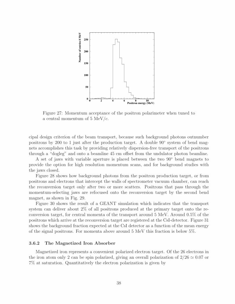
Positron energy (MeV)
Num
ber
of e
ntri
es/4
MeV
0
50
100
150
200
250
0 2 4 6 8 10
Figure 27: Momentum acceptance of the positron polarimeter when tuned toa central momentum of 5 MeV/c.
cipal design criterion of the beam transport, because such background photons outnumberpositrons by 200 to 1 just after the production target. A double 90 system of bend mag-nets accomplishes this task by providing relatively dispersion-free transport of the positronsthrough a “dogleg” and onto a beamline 45 cm offset from the undulator photon beamline.
A set of jaws with variable aperture is placed between the two 90 bend magnets toprovide the option for high resolution momentum scans, and for background studies withthe jaws closed.
Figure 28 shows how background photons from the positron production target, or frompositrons and electrons that intercept the walls of spectrometer vacuum chamber, can reachthe reconversion target only after two or more scatters. Positrons that pass through themomentum-selecting jaws are refocused onto the reconversion target by the second bendmagnet, as shown in Fig. 29.
Figure 30 shows the result of a GEANT simulation which indicates that the transportsystem can deliver about 2% of all positrons produced at the primary target onto the re-conversion target, for central momenta of the transport around 5 MeV. Around 0.5% of thepositrons which arrive at the reconversion target are registered at the CsI-detector. Figure 31shows the background fraction expected at the CsI detector as a function of the mean energyof the signal positrons. For momenta above around 5 MeV this fraction is below 5%.
3.6.2 The Magnetized Iron Absorber
Magnetized iron represents a convenient polarized electron target. Of the 26 electrons inthe iron atom only 2 can be spin polarized, giving an overall polarization of 2/26 0.07 or7% at saturation. Quantitatively the electron polarization is given by
38

primary target
spectrometerpositron
iron analyzer
reconversion targetCsI detector
Figure 28: Examples of trajectories of photons in the upstream part of thepositron polarimeter.
primary target
driftphoton
CsI detector
iron analyzer
spectrometerpositron
neutral beampipe
to photonpolarimeter
reconversion target
Figure 29: Examples of trajectories of positrons in the upstream part of thepositron polarimeter.
Pe = 2 · g′ − 1
g′ · M
n µB
(20)
where M = (B − Bo)/µo is the magnetization, n is the number of electrons per unit volume,µB is the Bohr magneton, and g
′is the gyromagnetic ratio which is known from Einstein-de
Haas type experiments [63].In order to attain the maximum possible polarization the iron must be magnetized to
saturation in the volume where the photons traverse the material. Fig. 32 shows the fielddistribution of a suitable iron and coil geometry that we have calculated and optimized withthe Opera-2d software from Vector Graphics.
The water-cooled coil has 360 turns and is operated at 100 Amperes. The volume ofinterest is 7.5 cm long x 5 cm diameter and will be fully in saturation, except for smallregions at the entrance and exit faces.
39

Mean Positron Energy (MeV)
Pro
babi
lity
for
posi
tron
tra
nspo
rt (
in %
)
0
0.5
1
1.5
2
2.5
3
3.5
0 2 4 6 8 10
Figure 30: The fraction, in per cent, of all positrons produced at the primarytarget that reach the reconversion target in the positron polarimeter, as afunction of the central momentum of the polarimeter.
Mean Positron Energy (MeV)
Fra
ctio
n of
bac
kgro
und
at d
etec
tor
0
0.01
0.02
0.03
0.04
0.05
0.06
0.07
0.08
0.09
0.1
0 2 4 6 8 10
Figure 31: Fraction of background events in the CsI detector, as a function ofthe central momentum of the polarimeter.
3.6.3 The CsI Calorimeter
The calorimeter for the detection of the photons radiated from the polarized positronswill be based on the technology developed for the BaBar experiment [64]. It will be a crystalcalorimeter with thallium-doped CsI crystals of typical dimensions: front face 4.7× 4.7 cm2,
40

OPERA-2Pre and Post-Processor 8.70
06/May/2003 12:53:18 Page 1
UNITSLength : mmFlux density : T Field strength : A mPotential : Wb Conductivity : S m-
Source density : A mPower : W Force : N Energy : J Mass : kg
PROBLEM DATAptp_japan4_neu_25.Quadratic elementsAxi-symmetryModified R*vec pot.Magnetic fieldsStatic solutionScale factor = 1.0 3758 elements 7655 nodes 6 regions
Z coord (mm) -38.0 -28.0 -18.0 -8.0 2.0 12.0 22.0 32.0
0.8
1.0
1.2
1.4
1.6
1.8
2.0
2.2
2.4
R = 23 mm
R = 20 mm
R = 15 mm
R = 10 mm
Figure 32: Calculated field map along the axis of the magnetized iron absorber.The vertical scale is the field in Tesla. The lowermost curve (unlabeled) is forthe field along the axis (R = 0).
rear face 6.0 × 6.2 cm2, and length 30 cm. Sixteen crystals will be stacked in a 4 × 4array inside a light-tight box. The box will be placed inside a lead housing to protect thecalorimeter against background radiation. At the front of the housing there is a circularopening that defines the acceptance of the calorimeter.
The scintillation of the crystals is detected from the rear end by two large area photodiodes (Hamamatsu S2744-08, active area 2 cm2 each). A preamplifier is mounted directlybehind the diodes, from where the signal is transferred to ADC’s. We plan to use the BaBarpreamps, but conventional ADC’s. BaBar has achieved light yields between 5000 and 10000photo electrons per MeV with two photo diodes.
The two diodes are glued onto a thin glass plate to improve the optical matching tothe CsI. The glass plate is then pressed against the back surface of the CsI by two springs.Optical grease will be used to improve the light coupling. The two diodes, the glass plateand the preamp will be mounted inside an aluminum housing (see Fig. 33. A cooling loopwill run along the walls to remove the heat created by the preamps. Flourinert will be usedas coolant to protect the crystals in case of leakage.
The 16 CsI crystals needed for the present experiment will be provided by SLAC (groupE) out of the pool of spare crystals for the BaBar experiment,purchased from SLAC stores.These crystals have photodiodes already mounted onto the coupling plates. A set of 32preamps and housing are also available.
3.7 Data-Acquisition System
For the measurements forseen by E-166, several parameters need to be set and data from
41

Figure 33: Mounting of the readout electronics on the end of a CsI crystal.
the apparatus need to be recorded. Table 11 shows some of these quantities.The data acquisition and control (DAQ) system has to record and display these data,
and possibly set other parameters. As the channel count and trigger frequency (30 Hz) arerather modest, an existing SLAC-provided PC running LabView is sufficient. This PC isinterfaced to a CAMAC crate housing the front-end electronics (ADC’s and such) with aGPIB card; other in- and output may be done with a PCI I/O board also installed in thePC.
The DAQ system is synchronized to the SLC/FFTB timing through a SLC PDU (Pro-grammable Delay Unit), which provides trigger pulses with a programmable delay, eithergenerated only when beam is present (’TRIG’), or always present (’TRBR’). For data-takingwith beam, trigger pulses are used to make gates pulses for the ADC conversions; after asuitable delay the PC will read out the digitized data from the CAMAC crate, display them,and write them to disk on the PC. The data will then be transferred to a SLAC Unix storagefor later off-line analysis.
A separate LabView process can read out a ‘Smart Analog Module’ (SAM) also presentin the CAMAC crate, asynchronously with the beam; the SAM collects beam data (en-ergy,positions, flux) from the SLAC Control System.
42

Table 11: Elements of the data-acquisition system. SLC = SLAC ControlSystem, DAQ = E-166 Data Acquisition System.
Device Quantity No. of Recorded by Pulsed (P)Measured Channels / set in or Slow (S)
Cerenkov/ Particle flux 2 DAQ PAerogel
Si/W Calor. Integrated 64 DAQ Pphoton energy
CsI Calor. Integrated 32 DAQ Pphoton energy
Iron magnet Field direction 2 DAQ S
Iron magnet Current 2 DAQ S
Undulator Current 1 SLC S
Toroid e− flux 1 SLC P
Beam energy 1 SLC S
Bunch length 1 SLC S
43

4 Measurements of Photon and Positron Polarization
The principal measurements in the proposed experiment are those of the flux and po-larization of the photon beam created in the helical undulator (sec. 3.3), and those of theflux and polarization of the positrons that are obtained from the undulator photons byconversion in a thin target (sec. 3.5). The polarization measurements are made with thetechnique of transmission polarimetry, whose principles have been introduced in secs. 2.3-4,with apparatus described in secs. 3.4 and 3.6.
Each 50-GeV electron is expected to produce 0.4 photons on average. In the case ofthe photon polarimeter, the transmission through the iron absorber is about 1%. Thus, for1 × 1010 electrons per pulse, 4 × 10⁹ photons per pulse are made, of which 4 × 10⁷ photonsarrive at the detector in the photon polarimeter.
For the positron studies, each photon pair-produces at a rate of about 0.005 positronsper photon in the primary target. About 2% of these positrons are transported to thereconversion target of the positron polarimeter, where roughly 1 photon per positron isregenerated. There is about a 0.25% transmission efficiency of photons from the reconversiontarget into the detector.
Thus, the 4 × 10⁹ undulator photons per pulse result in 2 × 10⁷ positrons per pulse. Ofthese, 4 × 10⁵ positrons are incident on the reconversion target and about 1 × 10³ photonsarrive at the detector in the positron polarimeter.
4.1 Undulator Photons
4.1.1 Flux
The flux of undulator photons of energy above 4.4 MeV is measured with the first of thetwo aerogel flux counters, shown in Fig. 19 and described in sec. 3.4.3. The signal in theseflux counters is due to Cerenkov radiation of electrons and positrons produced in interactionsof the undulator photons with a block of aerogel of index 1.007. The aerogel was chosen tobe insensitive to the synchrotron radiation from the bend magnets HSB1 and HSB2 (Fig. 18),whose critical energy is 110 keV and whose integrated photon number is comparable to thatof the undulator radiation. However, only the upper half of the undulator photon energyspectrum (Fig. 6(a)) is thereby monitored.
If it proves desirable to have a confirming measure of the flux of the entire spectrum ofundulator photons, the iron absorber of the photon polarimeter could be removed, and theSi-W calorimeter (sec. 3.4.2) used to measure the total energy in the photon beam.
A second aerogel flux counter, identical to the first, will be located downstream of theiron absorber in the photon polarimeter to monitor the flux of photons transmitted throughthat absorber. The ratio of rates in these two flux counters will be a good measure of thetransmission of the photons through the iron, since the transmission coefficient is essentiallyflat for photons of energy 5-10 MeV, as shown in Fig. 14(b).
4.1.2 Polarization
The polarization of undulator photons is to be measured in a transmission polarimeter
44

consisting of a 15-cm-long magnetized iron absorber followed by an aerogel flux counter anda Si-W calorimeter (sec. 3.4).
Polarimetry Using the Si-W Calorimeter
The expected spectrum and polarization of the undulator photons are shown in Figs. 6and 7. The energy-weighted average polarization of the undulator photons is 50% before theiron absorber, and 61% behind it.
The spectrum of photons that are transmitted through the iron absorber is shown inFig. 34(a), and the corresponding asymmetry on reversal of the magnetization of the iron isshown in Fig. 34(b).
Figure 34: (a) The number spectrum of undulator photons that penetratethrough the 15-cm magnetized iron absorber. The spectrum of photons inci-dent on the absorber is shown in Fig. 6(a). (b) The asymmetry of photonstransmitted through the iron absorber on reversal of its magnetic field.
When the photons that have penetrated the 15-cm-long iron absorber are observed inthe Si-W calorimeter, an energy-weighted asymmetry δ of 2.66% is expected, according tothe simulations.
We interpret this result as measurement of the energy-weighted mean transmitted photonpolarization, from eq. (17), ⟨
P Eγ
⟩=
δ
Pe
⟨AE
γ
⟩ , (21)
where Pe ≈ 0.07 is the net polarization of the electrons in the iron absorber, and⟨AE
γ
⟩≈ 0.62
is the energy-weighted analyzing power. The latter is calculated in a simulation of thetransmission asymmetry δ that would occur for a beam of photons of energy and polarizationspectra as in Fig. 6. This gives
⟨P E
γ
⟩=
0.0266
0.07 · 0.62= 0.61. (22)
45
Polarimetry Using the Aerogel Flux Counter
When the second aerogel flux counter is used for photon polarimetry, it records onlyphotons with energy above roughly 5 MeV, and with a signal size roughly independentof energy. In this case the photons are characterized by a number-weighted polarizationevaluated above the Cerenkov threshold.
Table 12 gives results of a simulation of photon polarization measurements as a functionof the threshold of the Cerenkov detector. For a 5-MeV Cerenkov threshold, the theoreticalnumber-weighted beam polarization
⟨P th
γ
⟩of the undulator photons is 75%. Only 0.84%
of all undulator photons penetrate the 15-cm-long iron absorber and have energy above 5MeV. The asymmetry in the detector on reversal of the magnetization is δ = 3.2% with thisthreshold, for which the analyzing power 〈Aγ〉 is 60%.
Errors
The statistical error on the measurement of the photon polarization is, to a good approx-imation when the asymmetry δ is small,
∆Pγ =1
Pe 〈Aγ〉
√4N+N−
N3≈ 1
Pe 〈Aγ〉√
N≈ 24√
N, (23)
where N = N+ + N− is the total number of photons observed in the detector. The approx-imation holds when the asymmetry δ is small, and the numbers N± of photons detected forthe two signs of Pe are nearly equal.
In an imagined data “run” that consisted of only a single pulse of each sign of themagnetization, the total number of photons that convert in the Cerenkov radiator is 36,000,assuming a detection probability of 0.0003 as discussed in Ch. 3.4.3, and the statistical erroron the measurement of the photon polarization would be 12% according to eq. (23). Hence,a total of 300 pulses (10 sec at 30 Hz operation) would be sufficient to obtain a statisticalerror of 1%.
The abundance of statistics is even more impressive for the Si-W calorimeter due to its100% detection probability. Since N+ ≈ N− ≈ 3 × 10⁷ per pulse, an experiment with onlya single pulse of each sign of Pe would have a statistical error on Pγ of only 0.3%.
The measurement of the photon polarization will be dominated by systematic uncertaintyin the electron polarization Pe and in the analyzing power 〈Aγ〉. The uncertainty in Pe isdue to uncertainty in the degree of saturation of the iron throughout the absorber, andis typically estimated at about 5%. The uncertainty in the calculation of Aγ is largelydetermined by uncertainty in geometric effects on the transmission of photons through theabsorber; i.e., on the probability that scattered photons find their way into the detectoralong with unscattered photons. With careful detector design, this uncertainty should be nomore than 1%.
46

Table 12: Simulated results of measurements of undulator photon polarizationas a function of the threshold energy of the Cerenkov detector downstreamof the iron absorber. Only one beam pulse is considered for each sign of themagnetization of the iron. Each of these pulses contains N0 = 4×10⁹ undulatorphotons. The number of photons detected in the Cerenkov detector is Nγ =2(εγ)(0.0003)N0, where 0.0003 is the probability that a photon converts in theCerenkov radiator.
Photon Photon Photon Photon Analyzing Nγ 2 pulse
Threshold Pol. Transport Asym. Power in 2 pulses Abs. Error
(MeV)⟨P th
γ
⟩(%) Eff. εγ (%) δ (%) 〈Aγ〉 (%) ∆Pγ (%)
0 42.1 2.13 1.9 64.6 47377 10
1 42.3 2.13 1.9 64.5 47328 10
2 45.4 2.08 2.0 63.8 46238 10
3 53.6 1.97 2.3 62.9 43650 11
4 64.6 1.81 2.8 61.7 40169 12
5 75.1 1.64 3.2 60.3 36336 12
6 83.6 1.43 3.4 58.8 31739 14
7 89.7 1.16 3.6 57.3 25813 16
8 93.1 0.81 3.6 56.0 18040 19
9 92.2 0.39 3.5 54.7 8649 28
4.2 Positrons
4.2.1 Flux
A momentum scan of the positrons produced by conversion of undulator photons in theprimary target can be made by temporarily removing the reconversion target and the ironabsorber from the positron polarimeter (Fig. 26). The jaws between the first and second 90
bend magnets will be reduced so the momentum acceptance is ±5% (compared to ±20% fornormal operation of the positron polarimeter). Then, the acceptance of the spectrometer forpositrons will be about 1/4 of that shown in Fig. 30, i.e., about 0.5%.
Of the 2 × 10⁷ positrons produced per pulse, about 105 would be detected during eachpulse of a scan of flux vs. momentum. Hence, a single pulse would suffice for each momentumsetting of the flux scan.
47

4.2.2 Polarization
As discussed in secs. 2.4 and 3.5 and shown in Fig. 26, the polarization of positrons isto be measured by transmission polarimetry of photons obtained by (re)conversion of thepositrons on a secondary target.
In a design study of the positron polarimeter [66], it was shown that its analyzing power(introduced in sec. 2.4) is insensitive to the thickness of the reconversion target, as summa-rized in Fig. 35. Indeed, it appears that it would suffice to use the magnetized iron itselfas the reconversion target. However, a separate reconversion target, 1.75-mm of tungsten,will be used. This will permit evaluation of possible background photons that are incidenton the reconversion target by short studies when the iron absorber is removed for the fluxmeasurements (sec. 4.2.1).
86420Thickness of W Reconversion Target (mm)
20
15
10
5
0
Ana
lyzi
ngP
owerAe
+(%
)
Ee + = 7 MeV
σ E / E = 20%
Figure 35: Simulation of the dependence of the energy-weighted analyzingpower of the positron polarimeter on the thickness of the reconversion targetfor a 7.5-cm-long iron absorber and the polarimeter geometry shown in Fig.26.
The analyzing power is also insensitive to the size of the momentum acceptance of thepolarimeter, as shown in Fig. 36. Therefore, the experiment can run with a relatively largeacceptance of ±20% around the central momentum (Fig. 27), and the rates in the positronpolarimeter will be reasonably high.
The analysis of the positron polarization will consist of a scan over the central momentumof the polarimeter from 3 to 10 MeV, collecting data for about 15 min at each setting.Table 13 presents simulated results for such a scan. The expected positron polarization hasbeen shown in Fig. 10. The efficiency of the positron transport from the primary target to thereconversion target is taken from Fig. 30. The expected asymmetry of reconversion photonsthat are detected in the CsI array on reversal of the magnetization of the iron absorber isbased on the positron polarization in the second column and on an electron polarizationPe of 7%. The energy-weighted analyzing power Ae+ for the positron polarimeter has been
48

3020100σ E / E (%)
20
15
10
5
0
Ana
lyzi
ngP
owerAe
+(%
)
Ee + = 7 MeV
Figure 36: Simulation of the dependence of the energy-weighted analyzingpower on the momentum acceptance of the positron polarimeter for a 7.5-cm-long iron absorber and the polarimeter geometry shown in Fig. 26.
presented in Fig. 17. In a 15-min run there are 27,000 pulses, for a total of Ne+ = 5.4× 10¹¹
positrons produced by the undulator photons.The positron polarization is reconstructed from the measured energy asymmetry δ =
(E+ − E−)/(E+ + E−)
Pe+ =δ
Pe−Ae+
, (24)
where Pe− is the net polarization of the electrons in the iron analyzer (Pe− ≈ 0.07) andAe+ is the associated energy-weighted analyzing power which must be determined from asimulation of the physical processes for the geometry of the polarimeter.
The statistical error on the measurement of the positron polarization is,
∆Pe+ =1
Pe−Ae+
√Nγ
, (25)
as summarized in the last column of Table 13, using Nγ = (εe+)(εe+→γ)(εγ)Ne+ , where εe+ isthe efficiency for transport of positrons from the primary target to the reconversion target,εe+→γ ≈ 1 is the reconversion efficiency and εγ is the efficiency for transport of reconversionphotons to the CsI array. The statistal errors shown in last column of Table 13 correspondto the polarimeter described in Table 10, a positron intensity of 2× 10⁷ per pulse, 30 pulsesper second, and a spectrometer transmission as shown in Fig. 30. This error only accountsfor photon statistics and does not include calorimeter-related resolution effects. The overallerror will be dominated by the systematic uncertainty in Pe− as discussed earlier.
49

Table 13: Simulated results of a scan of positron polarization vs. energy forthe example of a 7.5-cm-long iron absorber and the polarimeter geometryshown in Fig. 26. For each positron energy, 15 min data are collected, duringwhich Ne+ = 5.4× 10¹¹ positrons are generated from undulator photons. Thenumber of photons detected in the CsI array of the positron polarimeter isNγ = (εe+)(εe+→γ)(εγ)Ne+ , with εe+ and εγ as listed and εe+→γ ≈ 1. The15-min run is divided into two 7.5-min segments with opposite signs of themagnetization of the iron absorber. The detected photon asymmetry δ andthe associated analyzing power Ae+ are given for the energy-weighted signalsappropriate for a calorimeter detector.
Positron Positron Positron Photon Photon Analyzing Nγ 15 min
Energy Pol. Transport Transport Asym. Power in 15 min Abs.Error
(MeV) Pe+ (%) Eff. εe+ (%) Eff. εγ (%) δ (%) Ae+ (%) ∆Pe+ (%)
3 42 1.5 0.045 0.55 18.6 3.7 × 10⁶ 4.0
4 61 1.9 0.078 0.84 19.7 8.0 × 10⁶ 2.6
5 69 2.1 0.12 0.82 17.0 1.45 × 10⁷ 2.2
6 78 2.3 0.20 0.87 15.9 2.44 × 10⁷ 1.8
7 84 1.7 0.28 0.93 15.8 2.59 × 10⁷ 1.6
8 77 0.9 0.38 0.82 15.0 1.86 × 10⁷ 2.2
9 64 0.4 0.50 0.63 14.0 1.09 × 10⁷ 3.1
10 68 0.3 0.64 0.66 13.9 1.04 × 10⁷ 3.2
50
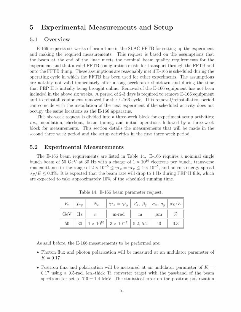
5 Experimental Measurements and Setup
5.1 Overview
E-166 requests six weeks of beam time in the SLAC FFTB for setting up the experimentand making the required measurements. This request is based on the assumptions thatthe beam at the end of the linac meets the nominal beam quality requirements for theexperiment and that a valid FFTB configuration exists for transport through the FFTB andonto the FFTB dump. These assumptions are reasonably met if E-166 is scheduled during theoperating cycle in which the FFTB has been used for other experiments. The assumptionsare notably not valid immediately after a long accelerator shutdown and during the timethat PEP II is initially being brought online. Removal of the E-166 equipment has not beenincluded in the above six weeks. A period of 2-3 days is required to remove E-166 equipmentand to reinstall equipment removed for the E-166 cycle. This removal/reinstallation periodcan coincide with the installation of the next experiment if the scheduled activity does notoccupy the same locations as the E-166 apparatus.
This six-week request is divided into a three-week block for experiment setup activities;i.e., installation, checkout, beam tuning, and initial operations followed by a three-weekblock for measurements. This section details the measurements that will be made in thesecond three week period and the setup activities in the first three week period.
5.2 Experimental Measurements
The E-166 beam requirements are listed in Table 14. E-166 requires a nominal singlebunch beam of 50 GeV at 30 Hz with a charge of 1 × 10¹⁰ electrons per bunch, transverserms emittance in the range of 2 × 10⁻⁵ ≤ γεx = γεy ≤ 4 × 10⁻⁵, and an rms energy spreadσE/E ≤ 0.3%. It is expected that the beam rate will drop to 1 Hz during PEP II fills, whichare expected to take approximately 10% of the scheduled running time.
Table 14: E-166 beam parameter request.
Ee frep Ne γεx = γεy βx, βy σx, σy σE/E
GeV Hz e− m-rad m µm %
50 30 1 × 10¹⁰ 3 × 10⁻⁵ 5.2, 5.2 40 0.3
As said before, the E-166 measurements to be performed are:
• Photon flux and photon polarization will be measured at an undulator parameter ofK = 0.17.
• Positron flux and polarization will be measured at an undulator parameter of K =0.17 using a 0.5-rad. len.-thick Ti converter target with the passband of the beamspectrometer set to 7.0 ± 1.4 MeV. The statistical error on the positron polarization
51

measurement is about 3% for 15 minutes of counting with a primary beam current of1 × 1010 e− per pulse and 30-Hz pulse rate.
• Photon flux and polarization will be measured as a function of strength parameter Kby varying the undulator current.
• Positron flux and polarization will be measured as a function of the central momentumof the spectrometer using an 0.5 r.l. thick pure Ti material converter target.
• Effect of target thickness will be measured with the spectrometer pass band fixed at7.0 ± 1.4 MeV for Ti targets of 0.1 rad. len. and 0.25 rad. len. and for W targets of0.1 rad. len., 0.25 rad. len., and 0.5 rad. len. The time to change a target sample isestimated to be about 2 hours.
• Each data set will take about 20 minutes per set, including the time to reverse mag-netization in the iron absorber.
It is estimated that less than one-third of the time will be spent on photon beam measure-ments. The remainder of the time will be spent on positron characterization. The analysisof the results will be prompt so that potential problems can be identified and fixed.
5.3 Experiment Setup
E-166 will need a three-week block of FFTB beam-time for installation of equipment, itscheckout on the beamline, beam tuning, and initial data taking to ensure that everythingworks. This initial three-week period is divided as follows:
• 1.5 weeks for installation, prebeam checkout and 50-GeV beam tuning in the linacenclosure;
• 0.5 weeks for beam tuning in the FFTB (primarily beam size tuning at the location ofthe undulator and upstream collimation for background reduction);
• 0.5 weeks for equipment checkout with beam;
• 0.5 weeks for initial data taking interspersed with tuning, background reduction, anddetector shielding.
At the end of this three week period E-166 will have been run as a complete system andwill be ready to make measurements.
5.3.1 Status of Required Beamline Equipment
Figures 18 and 19 show the layout of the E-166 beamline in the FFTB enclosure in thevicinity of IP1, and 35 m downstream of IP1, respectively. The devices BPM1, HSB1, OTR,Toro, and PRd are presently installed at the desired E-166 locations, while WS, BPM2, Au,the undulator, and HSB2 will require new installation (including cabling). Monitor BPM3
is presently installed but will be moved up stream by about 0.3 m; the existing cable for
52

BPM3 will reach to the new position. The dump magnet string D1 presently consists of 6permanent magnet dipoles, of which two are presently degaussed. For 50-GeV operation, aseventh permanent dipole magnet will be added at the downstream end of the D1 string,and all seven magnets re-energized. A power supply and cabling for this is already installedin the FFTB.
The magnet HSB2 is an existing device, but not presently installed in the FFTB; cablesneed to be pulled and a power supply will be borrowed from the SLC North Final FocusSystem (NFFS). Monitor BPM2 and associated electronics modules will be borrowed fromthe NFFS and replaced on completion of E-166. A set of BPM cables will be pulled. Rackspace and empty CAMAC slots are available in the Bldg. 407 for the needed additionalpower-supply and control modules.
The Short Pulse Photon Source (SPPS) diffraction grating chamber and associated vac-uum windows (not shown) are presently located about 14 m downstream of the dump magnetstring D1, and will be removed and replaced with a vacuum spool piece.
Profile monitor PRt, collimator At, and the Target are new installations. PRt will beborrowed from the SLAC NFFS and replaced upon completion of E-166. The target actuatoris a simple in/out device. New cabling is required for these devices.
The photon polarimeter consist of a pair of aerogel Cerenkov counters, a reversible ironmagnet and a silicon-tungsten calorimeter installed about two meters downstream of thepolarized positron production target.
The positron spectrometer consists of two 90 dipole bend magnets. These dipoles dis-place the produced positrons approximately 45-cm horizontally. The positron polarimeterconsists of an iron analyzer magnet and a shielded array of CsI crystals.
All these devices are new and will need power, diagnostics and readout cabling to be runfrom the FFTB enclosure to Bldg. 407.
Table 15 gives a status summary of the E-166 beamline equipment.
5.3.2 Installation and Check Out Requirements
Open access to the FFTB enclosure from the IP1 region to the downstream end of thehousing is required for a period of 1.5 weeks for installation and prebeam check out of the E-166 apparatus. Another 0.5 week of checkout with beam is required prior to commencementof full operations for the experiment. It is anticipated that installation of the beamlinecomponents in the IP1 and primary dumpline vicinity will be done in parallel with theinstallation of the target, spectrometer and polarimeters.
Five consecutive day shifts (Monday-Friday) are needed for installation and prebeamcheck out of beamline devices in the vicinity of IP1 and the primary beam dumpline. Thisis standard beamline work that will be performed by SLAC staff and includes installation,alignment, cabling, and pump out. Each new system will be tested and calibrated prior tostaging for installation. Because of the 1-mm apertures of the undulator and its protectioncollimator, the alignment of these devices is important.
The installation and prebeam check-out of the positron target system, spectrometer andpositron diagnostics as well as the photon diagnostics will be done by SLAC staff with E-166physicists also working on swing and owl shifts to make sure that the installed devices workas designed together with the control and data-acquisition system.
53

Table 15: Status of E-166 beamline equipment.
Device Description Status
BPM1 FFTB BPM Installed
HSB1 FFTB B04A Installed
OTR FFTB OTR beam profile monitor Installed
Toro FFTB Beam Toroid Current Monitor Installed
BPM2 SLC FFS BPM Relocate from SLAC NFFS†
WS FFTB Wire Scanner beam profile monitor Needs Installation†
Au Undulator protection collimator New†
Undulator 1-m helical undulator New†
BPM3 FFTB BPM Installed, needs repositioning
Hcor FFTB horizontal corrector Installed, needs repositioning
HSB2 FFTB B04B Exists, needs reinstallation
D1 FFTB Dump magnet string Needs augmentation
PRd FFTB Dump Screen Installed
SPPS DGB SPPS Diffraction Grating Box Replace w/ spool
PRt E-166 target screen Relocate from SLC NFFS†
At E-166 target collimator New†
Target Target actuator New†
D2 E-166 e+ spectrometer New†
γ Diag E-166 photon diagnostics New†
e+ Diag E-166 positron diagnostics New†
e− Dump E-166 electron dump New†
†Requires cabling
54

Checkout with beam is required to ensure that all beamline devices are functioning asspecified. This includes tests of the diagnostic devices with beam to compare with theexpected performance and of the data acquisition system to ensure that the experimentaldata can be successfully collected. A period of 0.5 weeks is allocated for this activity. Forthis checkout, a 10-Hz electron beam to the FFTB dump is required; as discussed below, theE-166 undulator will not be placed in the beamline during this initial beam checkout phase.
The detectors needed for E-166 will be installed, cabled, and commissioned during thefirst 1.5 weeks corresponding to the prebeam installation time. These devices and detectorsare associated with the photon and positron polarimetry and are listed in Table 16.
Table 16: Photon and positron polarimetry devices and detectors.
Photon Polarimetry
Incident photon flux monitor (Aerogel) †Iron block w/ support and mover
Trans. photon flux monitor (Aerogel) †Trans. photon energy monitor(Si-W Calorimeter) †
Positron Target Mover
Positron Extraction Line Dipole Pair
Positron Polarimetry
Positron-to-Photon converter target
Iron block w/ support and mover
CsI Calorimeter ††Detectors also require: HV Power Supplies; Front-end read-out electronics(with LV power); and Cabling from FFTB housing to Data Acquisitionelectronics in neighboring building.
The detectors will be assembled by E-166 collaborators and bench tested with theirassociated electronics. Tables and supports for these detectors on will be procured by SLACand can be installed ahead of the six weeks requested for E-166.
The mechanical installation is expected to be rather straightforward; however the physicalspace available must be managed very carefully due to the limited space in the FFTB tunnel.After the mechanical installation, a mechanical survey of the beamline components and E-166apparatus will be done.
Cables for power, control and data acquisition for the experiment must be pulled fromBldg. 407 into the FFTB enclosure. Most of this can be accomplished well before E-166 beam
55

time. After the detectors and their associated electronics have been cabled up, connectedwith the appropriate power supplies (HV/LV), and linked to the readout electronics and thedata-acquisition system in Bldg. 407, about 3 shifts without beam will be needed for theintegration of the detectors into the data-acquisition (DAQ) system, and at least one shiftwith beam to commission them. This task is simplified by the fact that the detectors willhave been tested on a similar DAQ system (currently LabView) and various settings such asHV for PMT’s and depletion voltages for silicon detectors will have been determined beforeinstallation.
Table 17 summarizes the installation and test plan for the detectors.
Table 17: Detector installation and test plan. Some tests might be performedby physicists during the weekend preceding beam delivery.
Day Activity
1 Install supports
2-4 Install detectors, iron blocks, cables, alignment survey
4-5 Connect detectors to HV/LV and DAQ
5-8 Test electronic readouts, DAQ system
A further 1-2 shifts is required for experiment commissioning with beam, for the finalsetting of trigger times, and possible last fixes of DAQ software and repair of any badhardware and dead read-out channels.
56

5.3.3 Beam Tuning and System Integration
Prior to E-166 running, the linac modulators, klystrons, and SLED systems will beprepared for 50-GeV operation at 30 Hz. When the FFTB is in Controlled Access, the fullenergy linac beam is parked on 52SL1 and 52SL2 using dipole 50B1; screen PR55 allowsobservation of the energy-resolved beam. This allows for linac tuning for 50-GeV operationto the beam switchyard during the 1.5 weeks of installation activities. The major steps inbeam tuning for E-166 through to the FFTB dump are listed below:
• Starting with a low emittance 30 GeV beam at end of linac, raise the linac energyto 50 GeV; steer, tune, and save configurations (done during the E-166 installationperiod).
• Re-establish 50-GeV beam from switchyard through to the FFTB dump. Start with thelast known good FFTB configuration scaled to 50 GeV and the last saved FFTB “gold”BPM orbit. With undulator removed, and a nominal 2-cm-I.D. beam pipe installed,steer beam to FFTB dump. Less than one shift will be needed to re-establish 50-GeVbeam from switchyard through to the FFTB dump.
• Spend one shift checking diagnostics with beam (everything should work as per pre-beam checkout.)
• Tune the nominal 40-µm rms spot size by loading in the DIMAD configuration andfocusing on the wire scanner before the undulator. Once the beam has been focusedonto the wire scanner, the beam waist can be shifted downstream by about 1 m to thecenter of the undulator using standard operating procedures. The estimated tuneuptime after nominal beam is on dump is expected to be six shifts.
• Once tuned, save reference orbits for steering feedbacks, save gold orbit, magnet set-tings.
• Shut off beam and install undulator. This is expected to take one shift.
• Bring back beams at low rate until full transmission through the undulator is achieved.
• Increase repetition rate to 10 Hz for diagnostics.
• Run up undulator current (should have negligible effect on beam), and look for undu-lator photons at PRt.
Three days are required to tune 50-GeV beam to FFTB dump, checkout diagnostics,and tune a small spot at IP1 with the undulator moved off the beamline. At this point theundulator is moved onto the beamline and E-166 is ready for commissioning the completesystem. This first week of commissioning will be spent making preliminary data runs, testingequipment, and repairing and replacing equipment as necessary.
57

6 References
[1] V.E. Balakin and A.A. Mikhailichenko, The Conversion System for Obtaining HighPolarized Electrons and Positrons, Budker Institute of Nuclear Physics, Preprint BINP79-85 (1979).
[2] K.C. Moffeit, Positron Source: First Fifty Nanoseconds, SLAC-CN-268 (May 1984);F. Bulos et al., Design of a High Yield Positron Source, SLAC-PUB-3635 (April 1985),IEEE Trans. Nucl. Sci. NS32, 1832 (1985),http://www.slac.stanford.edu/pubs/slacpubs/3000/slac-pub-3635.html
[3] The NLC Collaboration, N. Phinney ed., 2001 Report on the Next Linear Collider,SLAC-R-571 (June 2001), sec. 5.4,http://www.slac.stanford.edu/pubs/slacreports/slac-r-571.html
[4] K. Floettmann, Investigations Toward the Development of Polarized and UnpolarizedHigh Intensity Positron Sources for Linear Colliders, Ph.D. Thesis, DESY 93-161.
[5] New Kinds of Positron Sources for Linear Colliders, Proc. Stanford Workshop (March4-7, 1997), SLAC-R-0502
[6] T. Okugi, Y. Kurihara, M. Chiba, A. Endo, R. Hamatsu, T. Hirose, T. Kumita,T. Omori, Y. Takeuchi, and M. Yoshioka, Proposed Method to Make a Highly Polarizede+ Beam for Future Linear Colliders, Jpn.J.Appl.Phys. Vol.35 (1996) 3677.
[7] T. Omori, T. Aoki, K. Dobashi, T. Hirose, Y. Kurihara, T. Okugi, I. Sakai, A. Tsunemi,J. Urakawa, M. Washio, and K. Yokoya, Design of a Polarized Positron Source for LinearColliders, Nucl. Instr. Meth A500, 232 (2003) and Nucl. Instr. Meth. A503, 658 (2003).
[8] TESLA Technical Design Report, Chap. 4,http://tesla.desy.de/new pages/TDR CD/PartII/chapter04/chapter04.pdf
[9] Y.J. Batygin and J.C. Sheppard, Start-to-End Simulation of Polarized PositronCollection in the NLC, NLC Tech Note LCC-0117 (March 2003),http://www-project.slac.stanford.edu/lc/ilc/TechNotes/LCCNotes/PDF/LCC-0117%20text.pdf
[10] P. Raimondi et al., Recent Luminosity Improvements at the SLC, 17th Intl. Conf. onHigh-Energy Accl (HEACC 98), Dubna, Russia, SLAC-PUB-7955 (September 1998),http://www.slac.stanford.edu/cgi-wrap/getdoc/slac-pub-7955.pdf
[11] T. Hirose et al., Polarized Positron Source for the Linear Collider, JLC, Nucl. Instr.and Meth. A455, 15 (2000); K. Dobashi et al., Design of polarized-positron generationsystem, ibid. A455, 32 (2000).
[12] J.A. Aguilar-Saavedra et al., [ECFA/DESY LC Physics Working Group Collaboration],TESLA Technical Design Report Part III: Physics at an e+e− Linear Collider, hep-ph/0106315; T. Abe et al., [American Linear Collider Working Group Collaboration],
58

Linear Collider Physics Resource Book for Snowmass 2001 - Part 2: Higgs and Su-persymmetry Studies, in Proc. of the APS/DPF/DPB Summer Study on the Future ofParticle Physics (Snowmass 2001), ed. by N. Graf, hep-ex/0106056.
[13] G. Moortgat-Pick and H.M. Steiner, Physics Opportunities with Polarized e− and e+
Beams at TESLA, EPJdirect C, vol. 1, C6, 1 (2001), hep-ph/0106155; G. Moortgat-Pick, A Future Linear Collider with polarised beams: Searches for New Physics, hep-ph/0303234.
[14] C. Blochinger, H. Fraas, G. Moortgat-Pick and W. Porod, Selectron Pair Productionat e−e− and e+e− Colliders with Polarized Beams, Eur. Phys. J. C 24, 297 (2002),hep-ph/0201282.
[15] B.C. Allanach et al., The Snowmass Points and Slopes: Benchmarks for SUSY Searches,in Proc. of the APS/DPF/DPB Summer Study on the Future of Particle Physics (Snow-mass 2001 , ed. by N. Graf, Eur. Phys. J. C 25, 113 (2002), [eConf C010630, 125 (2001),hep-ph/0202233.
[16] M. Dima et al., Mass Determination Method for the Right and Left Selectron AboveProduction Threshold, Phys. Rev. D 65, 071701 (2002), hep-ex/0112017.
[17] See also the links on http://www.ippp.dur.ac.uk/˜gudrid/power/.
[18] J. Fleischer, K. Kolodziej and F. Jegerlehner, Transverse versus Longitudinal Polarisa-tion Effects in e+e− → W+W−, Phys. Rev. D 49, 2174 (1994).
[19] T. G. Rizzo, Transverse Polarization Signatures of Extra Dimensions at Linear Colliders,JHEP 0302, 008 (2003), hep-ph/0211374.
[20] R. Hawkings and K. Monig, Electroweak and CP Violation Physics at a Linear ColliderZ-factory, EPJdirect C, Vol. 1, C8, 1 (1999); K. Monig, LC–PHSM–2000–059; J. Erler,S. Heinemeyer, W. Hollik, G. Weiglein and P. M. Zerwas, Physics Impact of GigaZ,Phys. Lett. B 486, 125 (2000), hep-ph/0005024.
[21] D.F. Alferov, Yu.A. Bashmakov and E.G. Bessonov, Generation of Circularly PolarizedElectromagnetic Radiation, Sov. J. Tech. Phys. 21, 1408 (1976).
[22] B.M. Kincaid, A Short-period Helical Wiggler as an Important Source of SynchrotronRadiation, J. Appl. Phys. 48, 2684 (1977).
[23] J.P. Blewett and R. Chasman, Orbits and Fields in the Helical Wiggler, J. Appl. Phys.48, 2962 (1977).
[24] A.A. Mikhailichenko, Pulsed Helical Undulator for Test at SLAC. The Polarized Pro-duction Scheme, Cornell CBN 02-10, SLAC LCC106 (Sept. 16, 2002),http://www-project.slac.stanford.edu/lc/ilc/TechNotes/LCCNotes/PDF/LCC-0106
[25] J.C. Sheppard, Helical Undulator Radiation, SLAC LCC-0095 (July 2002),http://www-project.slac.stanford.edu/lc/ilc/TechNotes/LCCNotes/PDF/LCC-0095
59

[26] G.Ya. Kezerashvili et al., Collding Beam Polarization Measurement Using Supercon-ducting Helical Undulator at the VEPP-2M Storage Ring, Nucl. Instr. and Meth. A314,15 (1992).
[27] R. Carr et al., Performance of the Elliptically Polarizing Undulator on SPEAR, SLAC-PUB-6627 (Oct. 1995), Rev. Sci. Instrum. 66, 1862 (1995),http://www.slac.stanford.edu/pubs/slacpubs/6000/slac-pub-6627.html
[28] H. Olsen and L.C. Maximon, Photon and Electron Polarization in High-EnergyBremsstrahlung and Pair Production with Screening, Phys. Rev. 114, 887 (1959).
[29] J.C. Liu et al., Polarization Study for NLC Positron Source Using EGS4, SLAC-PUB-8477 (June 16, 2000),http://www.slac.stanford.edu/cgi-wrap/getdoc/slac-pub-8477.pdf
[30] W.R. Nelson, H. Hirayama and D.W.O. Rogers, The EGS4 Code System, SLAC-Report-265, (1985).
[31] H. Hoogduin, Electron, Positron and Photon Polarimetry, Ph.D. Thesis, University ofGroningen, ISBN: 90-367-0737-4 (1997).
[32] F.W. Lipps and H.A. Tolhoek, Polarization Phenoma of Electrons and Photons. I. Gen-eral Method and Application to Compton Scattering, Physica 20, 85 (1954); Polariza-tion Phenoma of Electrons and Photons. II. Results for Compton Scattering, Physica20, 395 (1954).
[33] L.W. Fagg and S.W. Hanna, Polarization Measurements on Nuclear Gamma Rays, Rev.Mod. Phys. 31, 711 (1959).
[34] H. Frauenfelder and A. Rossi, Determination of the Polarization of Electrons and Pho-tons, in Methods of Experimental Physics. Nucl. Physics, Part B5, ed. by L.C.L. Yuanand C.-S. Wu (Academic Press, New York, 1963), pp. 214-274.
[35] J.C. Wheatley et al., Circular Polarization of Gamma Radiation Emitted by OrientedCo-40 Nuclei, Physica 21, 841 (1955).
[36] S.B. Gunst and L.A. Page, Compton Scattering of 2.62 MeV Gamma Rays by PolarizedElectrons, Phys. Rev. 92, 970 (1953).
[37] H. Schopper, Measurement of Circular Polarization of γ-rays, Nucl. Instr. and Meth.3, 158 (1958),http://www-project.slac.stanford.edu/lc/local/PolarizedPositrons/doc/ClassicalPapers/Schopper.pdf
[38] M. Fukuda et al., Polarimetry of Short Pulse Gamma-Rays and Positrons, in Proc. 2ndAsian Part. Accel. Conf. (Beijing, China, 2001), p. 881;
60

M. Fukuda, T. Aoki, K. Dobashi, T. Hirose, T. Iimura, Y. Kurihara, T. Okugi, T. Omori,I. Sakai, J. Urakawa, and M. Washio, Polarimetry of Short-Pulse Gamma-Rays Pro-duced through Inverse Compton Scattering of Circularly Polarized Laser Beams, KEKPreprint 2003-05, submitted to Phys. Rev. Lett.
[39] XCOM: Photon Cross Sections Database (Nat. Inst. Standards),http://physics.nist.gov/PhysRefData/Xcom/Text/XCOM.html
[40] L.A. Page, Polarization Effects in the Two-Quantum Annihilation of Positrons, Phys.Rev. 106, 394 (1957).
[41] William H. McMaster, Matrix Representation of Polarization, Rev. Mod. Phys. 33, 8(1961).
[42] A. Buhler et al., A Measurement of the e+ Polarization in Muon Decay: The e+ Anni-hilation Method, Phys. Lett. 7, 368 (1963).
[43] A.M. Bincer, Scattering of Longitudinally Polarized Fermions, Phys. Rev. 107, 1344(1957).
[44] G.W. Ford and C.J. Mullin, Scattering of Polarized Dirac Particles on Electrons, Phys.Rev. 108, 477 (1957).
[45] J.D. Ullmann, H. Frauenfelder, H.J. Lipkin, and A. Rossi, Determination of Electronand Positron Helicity with Møller and Bhabha Scattering, Phys. Rev. 122 (1961) 536.http://prola.aps.org/pdf/PR/v122/i2/p536 1
[46] J. Duclos et al., Measurement of the e+ Polarization in Muon Decay by Means of BhabhaScattering, Phys. Lett. 9, 62 (1964).
[47] F. Corriveau et al., Measurement of the Positron Longitudinal Polarization in MuonDecay, Phys. Rev. D 24, 2004 (1981).
[48] R.L. Gluckstern, M.H. Hull, Jr., and G. Breit, Polarization of Bremsstrahlung Radia-tion, Phys. Rev. 90, 1026 (1953).
[49] C. Fronsdahl and H. Uberall, Polarization of Bremsstrahlung from Polarized Electrons,Phys. Rev. 111, 580 (1958); Nuovo Cim. 8, 163 (1958).
[50] G. Culligan et al., Nature 180, 751 (1957).
[51] M. Goldhaber, L. Grodzins, and A.W. Sunyar, Evidence for Circular Polarization ofBremsstrahlung Produced by Beta Rays, Phys. Rev. 106, 826 (1957).
[52] P.C. Macq, K.M. Crowe and R.P. Haddock, Helicity of the Electron and Positron inMuon Decay, Phys. Rev. 112, 2061 (1958).
[53] S. Bloom et al., Measurement, by Bremsstrahlung Transmission, of the Polarization ofe+ from µ+ → e+ + νe + νµ, Phys. Lett. 8, 87 (1964).
61

[54] T. Zwart et al., Transmission Polarimetry at MIT Bates: Towards an Absolute Po-larimeter?,http://mitbates.mit.edu/pesp2002/talks/ZwartXPO-PESP2002.pdf
[55] T. Hirose, Development of Picosecond CO2 Laser for Production of Polarized Positronsat Linear Colliders (April 30, 2003),http://heal1.phys.metro-u.ac.jp/˜kumita/US-Japan/progress-final.pdf
[56] S.M. Harris and R.J. Jabbur, On Depolarization of Fast Positrons by Bremsstrahlung,Nuovo Cimento 32, 258 (1964).
[57] C. Bouchiat and J.M. Levy-Leblond, Depolarization of Electrons in Matter, NuovoCimento 33, 193 (1964).
[58] W. Chinowsky, D. Cutts, and R. Stiening, Nuovo Cimento 34, 1431 (1964).
[59] Y. Batygin, Particle-in-cell code BEAMPATH for Beam Dynamics Simulations withSpace Charge, ISSN 1344-3877, RIKEN AF-AC-17 (2000).
[60] C. Bamber et al., Studies of Nonlinear QED in Collisions of 46.6 GeV Electrons withIntense Laser Pulses, Phys. Rev. D 60, 092004 (1999).
[61] A. Mikhailichenko, Pulsed Undulator for Test at SLAC of Polarized Positron Produc-tion, CBN-03-05 (April 10, 2003),http://puhep1.princeton.edu/˜mcdonald/e166/CBN 03-5.pdf
[62] MERMAID/3D, SIM Inc., Novosibirsk, P.O. Box 402, Russia.
[63] G.G. Scott, Review of Gyromagnetic Ratio Experiments, Rev. Mod. Phys. 34, 102(1962).
[64] B. Aubert et al., The BaBar Detector, Nucl. Instr. and Meth. A479 1, (2002).
[65] M. Woods et al., Design Studies for Flux and Polarization Measurements of Photonsand Positrons for SLAC Proposal E166, SLAC LCC-0107 (Nov. 6, 2002),http://www-project.slac.stanford.edu/lc/ilc/TechNotes/LCCNotes/PDF/LCC-0107%20text.pdf
[66] V. Gharibyan and K. P. Schuler, The Positron Polarimeter for the SLAC FFBTUndulator Experiment (May 2003),http://www-project.slac.stanford.edu/lc/local/PolarizedPositrons/internal/doc/2003/2003-05-12-ps-pospol.ps.gz
62
Related Documents