SCIENTIFIC MANIFEST 2 UNDERWATER UNDERWATER ACOUSTIC ACOUSTIC POSITIONING SYSTEM POSITIONING SYSTEM A.PO.MA.B. merely to collect and publish information of the topic in question. This brief illustration is the ocean underwater positioning system, can be used for educational purposes only and not for operational use. A.PO.MA.B. does not assume any responsibility for the operational use of this treaty. A special thanks to Dr. Patrizio Di Benedetto-Archaeologist, Mr. Digiugno Calcedonio Daniele-Mining Surveyor, Mr. Liggieri Sebastiano Giovanni-Surveyor and Mr. Spadaro Andrea-Surveyor for thorough research and page setting of the text. A.PO.MA.B. – SCIENTIFIC MANIFEST - 2 - Pag. 1 of 33

Welcome message from author
This document is posted to help you gain knowledge. Please leave a comment to let me know what you think about it! Share it to your friends and learn new things together.
Transcript
SCIENTIFIC MANIFEST 2
UNDERWATER UNDERWATER ACOUSTICACOUSTIC
POSITIONING SYSTEMPOSITIONING SYSTEM
A.PO.MA.B. merely to collect and publish information of the topic in question.
This brief illustration is the ocean underwater positioning system, can be used for educational purposes only and not for operational use.
A.PO.MA.B. does not assume any responsibility for the operational use of this treaty.
A special thanks to Dr. Patrizio Di Benedetto-Archaeologist, Mr. Digiugno Calcedonio Daniele-Mining Surveyor, Mr. Liggieri Sebastiano Giovanni-Surveyor and Mr. Spadaro Andrea-Surveyor for thorough research and page setting of the text.
A.PO.MA.B. – SCIENTIFIC MANIFEST - 2 - Pag. 1 of 33

Intentionally left blank
A.PO.MA.B. – SCIENTIFIC MANIFEST - 2 - Pag. 2 of 33
OBJECT: Underwater Acoustic Positioning SystemAn Vessal is a system for the tracking and navigation of underwater vehicles or divers by means of acoustic distance and/or direction measurements, and subsequent position triangulation. Underwater Acoustic Positioning Systems are commonly used in a wide variety of underwater work, including oil and gas exploration, ocean sciences, salvage operations, marine archaeology, law enforcement and military activities.
CONTENTS• Underwater Acoustic Positioning System
• 1 - Method of Operation• 2 - Underwater Acoustic Positioning System Classes
• 3 - History and Examples of Use
• Long Baseline (LBL)
• 4 - Method of Operation and Performance Characteristics
• 5 - History and Examples of Use o 5.1 - Offshore
• 6 - USBL
• Short Baseline Acoustic Positioning System SBL
• 7 - Method of Operation and Performance Characteristics
• 8 - History and Examples of Use o 8.1 - Example of SBL System Use: Under-The-
Ice Surveying by ROV in Antarctica
• GPS Intelligent Buoys
• 9 - History and Examples of Use• 10 - Example of Underwater Acoustic-based Weapon
Scoring
• References
A.PO.MA.B. – SCIENTIFIC MANIFEST - 2 - Pag. 3 of 33

Intentionally left blank
A.PO.MA.B. – SCIENTIFIC MANIFEST - 2 - Pag. 4 of 33
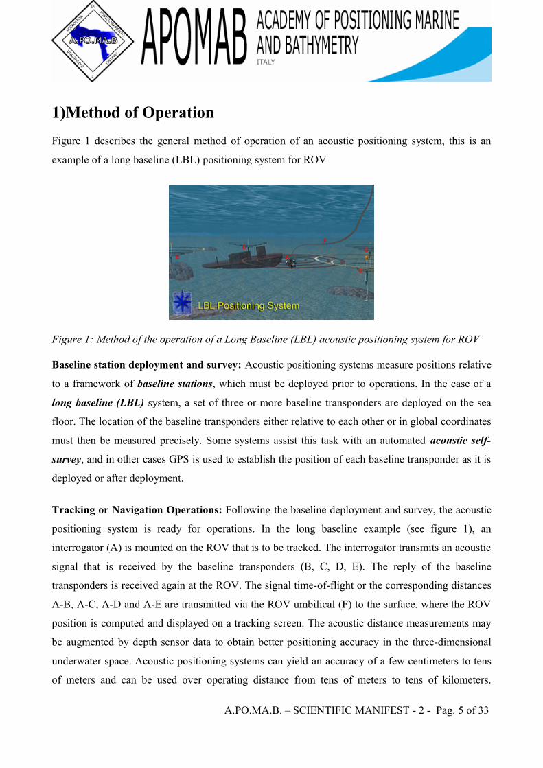
1)Method of OperationFigure 1 describes the general method of operation of an acoustic positioning system, this is an
example of a long baseline (LBL) positioning system for ROV
Figure 1: Method of the operation of a Long Baseline (LBL) acoustic positioning system for ROV
Baseline station deployment and survey: Acoustic positioning systems measure positions relative
to a framework of baseline stations, which must be deployed prior to operations. In the case of a
long baseline (LBL) system, a set of three or more baseline transponders are deployed on the sea
floor. The location of the baseline transponders either relative to each other or in global coordinates
must then be measured precisely. Some systems assist this task with an automated acoustic self-
survey, and in other cases GPS is used to establish the position of each baseline transponder as it is
deployed or after deployment.
Tracking or Navigation Operations: Following the baseline deployment and survey, the acoustic
positioning system is ready for operations. In the long baseline example (see figure 1), an
interrogator (A) is mounted on the ROV that is to be tracked. The interrogator transmits an acoustic
signal that is received by the baseline transponders (B, C, D, E). The reply of the baseline
transponders is received again at the ROV. The signal time-of-flight or the corresponding distances
A-B, A-C, A-D and A-E are transmitted via the ROV umbilical (F) to the surface, where the ROV
position is computed and displayed on a tracking screen. The acoustic distance measurements may
be augmented by depth sensor data to obtain better positioning accuracy in the three-dimensional
underwater space. Acoustic positioning systems can yield an accuracy of a few centimeters to tens
of meters and can be used over operating distance from tens of meters to tens of kilometers.
A.PO.MA.B. – SCIENTIFIC MANIFEST - 2 - Pag. 5 of 33

Performance depends strongly on the type and model of the positioning system, its configuration for
a particular job, and the characteristics of the underwater acoustic environment at the work site.
A.PO.MA.B. – SCIENTIFIC MANIFEST - 2 - Pag. 6 of 33
2)Underwater Acoustic Positioning System ClassesUnderwater acoustic positioning systems are generally categorized into three broad types or classes
Long Baseline (LBL) Systems: Long baseline systems, as in figure 1 above, use a sea-floor
baseline transponder network. The transponders are typically mounted in the corners of the
operations site. LBL systems yield very high accuracy of generally better than 1 m and sometimes
as good as 0.01m along with very robust positions. This is due to the fact that the transponders are
installed in the reference frame of the work site itself (i.e. on the sea floor), the wide transponder
spacing results in an ideal geometry for position computations, and the LBL system operates
without an acoustic path to the (potentially distant) sea surface.
Ultra Short Baseline (USBL) Systems: USBL systems and the related super short baseline (SSBL)
systems rely on a small (ex. 230 mm across), tightly integrated transducer array that is typically
mounted on the bottom end of a strong, rigid transducer pole which is installed either on the side or
in some cases on the bottom of a surface vessel[8][9]. Unlike LBL and SBL systems, which determine
position by measuring multiple distances, the USBL transducer array is used to measure the target
distance from the transducer pole by using signal run time, and the target direction by measuring
the phase shift of the reply signal as seen by the individual elements of the transducer array. The
combination of distance and direction fixes the position of the tracked target relative to the surface
vessel. Additional sensors including GPS, a gyro or electronic compass and a vertical reference unit
are then used to compensate for the changing position and orientation (pitch, roll, bearing) of the
surface vessel and its transducer pole. USBL systems offer the advantage of not requiring a sea
floor transponder array. The disadvantage is that positioning accuracy and robustness is not as good
as for LBL systems. The reason is that the fixed angle resolved by a USBL system translates to a
larger position error at greater distance. Also, the multiple sensors needed for the USBL transducer
pole position and orientation compensation each introduce additional errors. Finally, the non-
uniformity of the underwater acoustic environment cause signal refractions and reflections that have
a greater impact on USBL positioning than is the case for the LBL geometry.
A.PO.MA.B. – SCIENTIFIC MANIFEST - 2 - Pag. 7 of 33
Short Baseline (SBL) Systems: Short baseline systems use a baseline consisting of three or more
individual sonar transducers that are connected by wire to a central control box. Accuracy depends
on transducer spacing and mounting method. When a wider spacing is employed as when working
from a large working barge or when operating from a dock or other fixed platform, the performance
can be similar to LBL systems. When operating from a small boat where transducer spacing is tight,
accuracy is reduced. Like USBL systems, SBL systems are frequently mounted on boats and ships,
but specialized modes of deployment are common too. For example, the Woods Hole
Oceanographic Institution uses a SBL system to position the Jason deep-ocean ROV relative to its
associated MEDEA depressor weight with a reported accuracy of 9 cm.
GPS Intelligent Buoys (GIB): GIB systems are inverted LBL devices where the transducers are
replaced by floating buoys, self-positionned by GPS. The tracked position is calculated in realtime
at the surface from the Time-Of-Arrival (TOAs) of the acoustic signals sent by the underwater
devic, and acquired by the buoys. Such configuration allow fast, calibration-free deployment with
an accuracy similar to LBL systems. At the opposite of LBL, SBL ou USBL systems, GIB systems
use one-way acoustic signals from the emitter to the buoys, making it less sensible to surface or
wall reflections. GIB systems are used to track AUVs, torpedoes, or divers, may be used to localize
airplanes black-boxes, and may be used to determine the impact coordinates of inert or live
weapons for weapon testing and training purposes references: Sharm-El-Sheih, 2004; Sotchi, 2006;
Kayers, 2005; Kayser, 2006; Cardoza, 2006 and others...).
A.PO.MA.B. – SCIENTIFIC MANIFEST - 2 - Pag. 8 of 33
3)History and Examples of Use
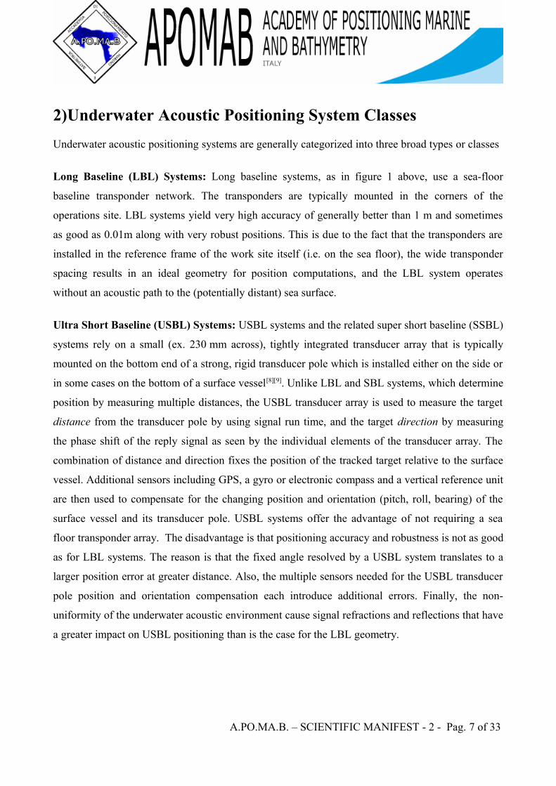
Figure 2a: An acoustic short baseline (SBL) positioning system was installed on the USNS Mizar
during the search dives to the wreckage of the submarine USS Thresher
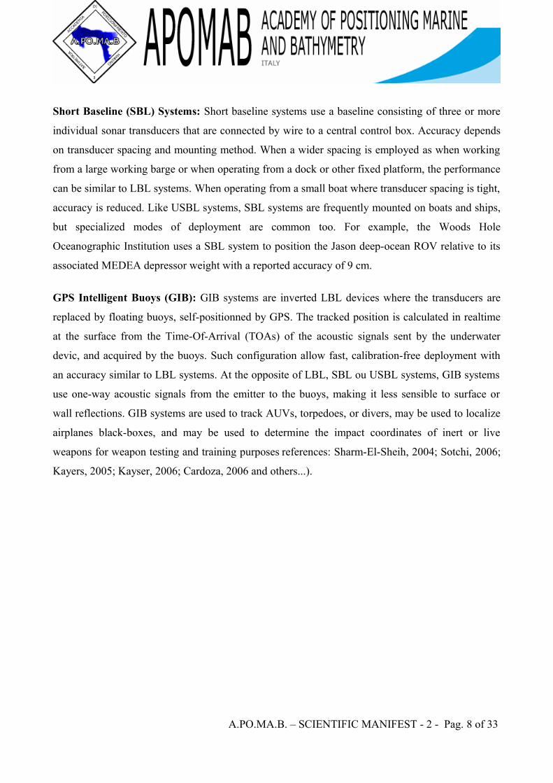
Figure 2b: The bathyscaphe Trieste was guided by that acoustic positioning system to the Thresher
An early use of underwater acoustic positioning systems, credited with initiating the modern day
development of these systems, involved the loss of the American nuclear submarine USS Thresher
on 10 April 1963 in a water depth of 2560m. An acoustic short baseline (SBL) positioning system
was installed on the oceanographic vessel USNS Mizar. This system was used to guide the
bathyscape Trieste 1 to the wreck site. Yet, the state of the technology was still so poor that out of
ten search dives by Trieste 1, visual contact was only made once with the wreckage [16]. Acoustic
positioning was again used in 1966, to aid in the search and subsequent recovery of a nuclear bomb
lost during the crash of a B-52 bomber at sea off the coast of Spain.
A.PO.MA.B. – SCIENTIFIC MANIFEST - 2 - Pag. 9 of 33
In the 1970s, oil and gas exploration in deeper waters required improved underwater positioning accuracy to place drill strings into the exact position referenced earlier thorough seismic instrumentation and to perform other underwater construction tasks.
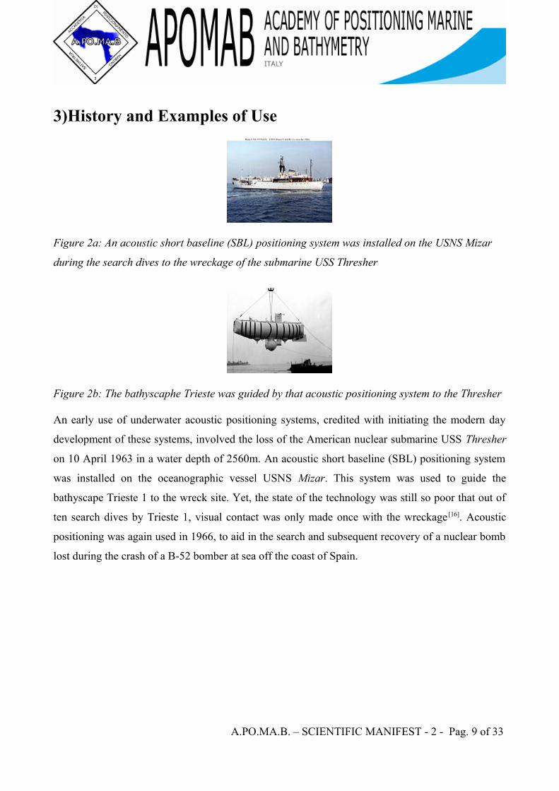
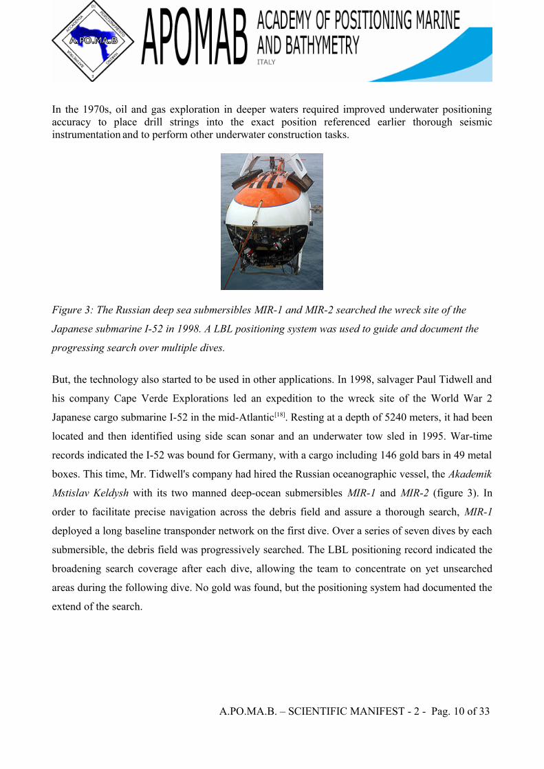
Figure 3: The Russian deep sea submersibles MIR-1 and MIR-2 searched the wreck site of the
Japanese submarine I-52 in 1998. A LBL positioning system was used to guide and document the
progressing search over multiple dives.
But, the technology also started to be used in other applications. In 1998, salvager Paul Tidwell and
his company Cape Verde Explorations led an expedition to the wreck site of the World War 2
Japanese cargo submarine I-52 in the mid-Atlantic[18]. Resting at a depth of 5240 meters, it had been
located and then identified using side scan sonar and an underwater tow sled in 1995. War-time
records indicated the I-52 was bound for Germany, with a cargo including 146 gold bars in 49 metal
boxes. This time, Mr. Tidwell's company had hired the Russian oceanographic vessel, the Akademik
Mstislav Keldysh with its two manned deep-ocean submersibles MIR-1 and MIR-2 (figure 3). In
order to facilitate precise navigation across the debris field and assure a thorough search, MIR-1
deployed a long baseline transponder network on the first dive. Over a series of seven dives by each
submersible, the debris field was progressively searched. The LBL positioning record indicated the
broadening search coverage after each dive, allowing the team to concentrate on yet unsearched
areas during the following dive. No gold was found, but the positioning system had documented the
extend of the search.
A.PO.MA.B. – SCIENTIFIC MANIFEST - 2 - Pag. 10 of 33
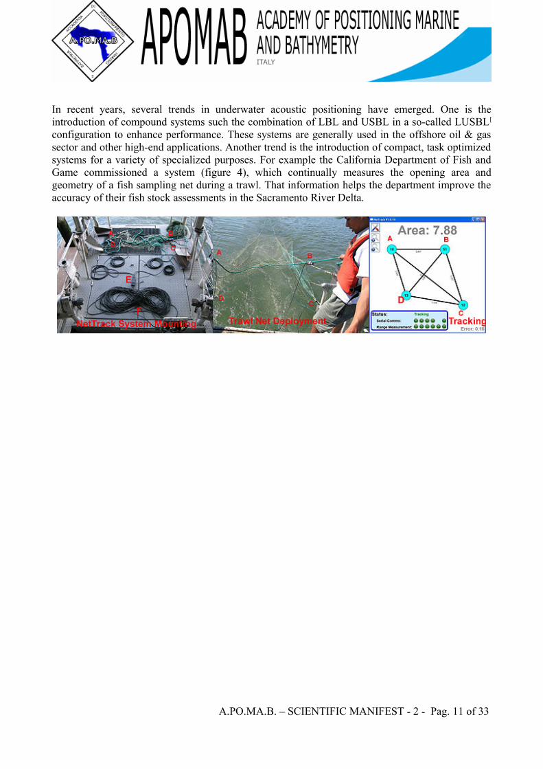
In recent years, several trends in underwater acoustic positioning have emerged. One is the introduction of compound systems such the combination of LBL and USBL in a so-called LUSBL[
configuration to enhance performance. These systems are generally used in the offshore oil & gas sector and other high-end applications. Another trend is the introduction of compact, task optimized systems for a variety of specialized purposes. For example the California Department of Fish and Game commissioned a system (figure 4), which continually measures the opening area and geometry of a fish sampling net during a trawl. That information helps the department improve the accuracy of their fish stock assessments in the Sacramento River Delta.
A.PO.MA.B. – SCIENTIFIC MANIFEST - 2 - Pag. 11 of 33

Intentionally left blank
A.PO.MA.B. – SCIENTIFIC MANIFEST - 2 - Pag. 12 of 33
Long Baseline Acoustic Positioning SystemA Long Baseline (LBL) Acoustic Positioning System is one of three broad classes of underwater
acoustic positioning systems that are used to track underwater vehicles and divers. The other two
classes are Ultra Short Baseline Systems (USBL) and Short Baseline Systems (SBL). LBL systems
are unique in that they use networks of sea-floor mounted baseline transponders as reference points
for navigation. These are generally deployed around the perimeter of a work site. The LBL
technique results in very high positioning accuracy and position stability that is independent of
water depth. It is generally better than 1-meter and can reach a few centimeters accuracy. LBL
systems are generally employed for precision underwater survey work where the accuracy or
position stability of ship-based (SBL, USBL) positioning systems does not suffice.
A.PO.MA.B. – SCIENTIFIC MANIFEST - 2 - Pag. 13 of 33
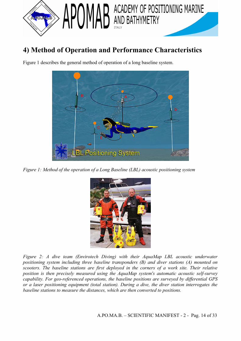
4) Method of Operation and Performance CharacteristicsFigure 1 describes the general method of operation of a long baseline system.
Figure 1: Method of the operation of a Long Baseline (LBL) acoustic positioning system
Figure 2: A dive team (Envirotech Diving) with their AquaMap LBL acoustic underwater positioning system including three baseline transponders (B) and diver stations (A) mounted on scooters. The baseline stations are first deployed in the corners of a work site. Their relative position is then precisely measured using the AquaMap system's automatic acoustic self-survey capability. For geo-referenced operations, the baseline positions are surveyed by differential GPS or a laser positioning equipment (total station). During a dive, the diver station interrogates the baseline stations to measure the distances, which are then converted to positions.
A.PO.MA.B. – SCIENTIFIC MANIFEST - 2 - Pag. 14 of 33
Long baseline systems determine the position of a vehicle or diver by acoustically measuring the
distance from a vehicle or diver interrogator to three or more seafloor deployed baseline
transponders. These range measurements, which are often supplemented by depth data from
pressure sensors on the devices, are then used to triangulate the position of the vehicle or diver. In
figure 1, a diver mounted interrogator (A) sends a signal, which is received by the baseline
transponders (B, C, D). The transponders reply, and the replies are received again by the diver
station (A). Signal run time measurements now yield the distances A-B, A-C and A-D, which are
used to compute the diver position by triangulation or position search algorithms. The resulting
positions are relative to the location of the baseline transducers. These can be readily converted to a
geo-referenced coordinate system such as latitude/longitude or UTM if the geo-positions of the
baseline stations are first established.
Long baseline systems get their name from the fact that the spacing of the baseline transponders is
long or similar to the distance between the diver or vehicle and the transponders.That is, the
baseline transponders are typically mounted in the corners of an underwater work site within which
the vehicle or diver operates. This method yields an ideal geometry for positioning, in which any
given error in acoustic range measurements produce only about an equivalent position error. This
compares to SBL and USBL systems with shorter baselines where ranging disturbances of a given
amount can result in much larger position errors. Further, the mounting of the baseline transponders
on the sea floor eliminates the need for converting between reference frames, as is the case for
USBL or SBL positioning systems mounted on moving vessels. Finally, sea floor mounting makes
the positioning accuracy independent of water depth.For these reasons LBL systems are generally
applied to tasks where the required standard of positioning accuracy or reliability exceeds the
capabilities of USBL and SBL systems.
A.PO.MA.B. – SCIENTIFIC MANIFEST - 2 - Pag. 15 of 33

Intentionally left blank
A.PO.MA.B. – SCIENTIFIC MANIFEST - 2 - Pag. 16 of 33
5)History and Examples of Use
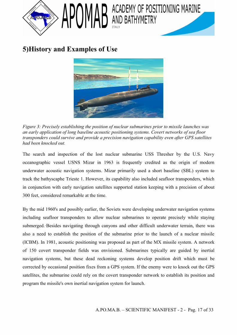
Figure 3: Precisely establishing the position of nuclear submarines prior to missile launches was an early application of long baseline acoustic positioning systems. Covert networks of sea floor transponders could survive and provide a precision navigation capability even after GPS satellites had been knocked out.
The search and inspection of the lost nuclear submarine USS Thresher by the U.S. Navy
oceanographic vessel USNS Mizar in 1963 is frequently credited as the origin of modern
underwater acoustic navigation systems. Mizar primarily used a short baseline (SBL) system to
track the bathyscaphe Trieste 1. However, its capability also included seafloor transponders, which
in conjunction with early navigation satellites supported station keeping with a precision of about
300 feet, considered remarkable at the time.
By the mid 1960's and possibly earlier, the Soviets were developing underwater navigation systems
including seafloor transponders to allow nuclear submarines to operate precisely while staying
submerged. Besides navigating through canyons and other difficult underwater terrain, there was
also a need to establish the position of the submarine prior to the launch of a nuclear missile
(ICBM). In 1981, acoustic positioning was proposed as part of the MX missile system. A network
of 150 covert transponder fields was envisioned. Submarines typically are guided by inertial
navigation systems, but these dead reckoning systems develop position drift which must be
corrected by occasional position fixes from a GPS system. If the enemy were to knock out the GPS
satellites, the submarine could rely on the covert transponder network to establish its position and
program the missile's own inertial navigation system for launch.
A.PO.MA.B. – SCIENTIFIC MANIFEST - 2 - Pag. 17 of 33

5.1) Offshore
LBL diver technology has continued to advance, and the DS-3 terminal (figure 5) includes graphic information similar to that of mapping GPS receivers.
A.PO.MA.B. – SCIENTIFIC MANIFEST - 2 - Pag. 18 of 33
6) Ultra-short baselineUSBL (Ultra-short baseline) is a method of underwater acoustic positioning. A complete USBL
system consists of a transceiver, which is mounted on a pole under a ship, and a
transponder/responder on the seafloor, a towfish, or on a ROV. A computer, or "topside unit", is
used to calculate a position from the ranges and bearings measured by the transceiver.
An acoustic pulse is transmitted by the transceiver and detected by the subsea transponder, which
replies with its own acoustic pulse. This return pulse is detected by the shipboard transceiver. The
time from the transmission of the initial acoustic pulse until the reply is detected is measured by the
USBL system and is converted into a range.
To calculate a subsea position, the USBL calculates both a range and an angle from the transceiver
to the subsea beacon. Angles are measured by the transceiver, which contains an array of
transducers. The transceiver head normally contains three or more transducers separated by a
baseline of 10 cm or less. A method called “phase-differencing” within this transducer array is used
to calculate the angle to the subsea transponder.
USBLs have also begun to find use in "inverted" (iUSBL) configurations, with the transceiver
mounted on an autonomous underwater vehicle, and the transponder on the target. In this case, the
"topside" processing happens inside the vehicle to allow it to locate the transponder for applications
such as automatic docking and target tracking.
A.PO.MA.B. – SCIENTIFIC MANIFEST - 2 - Pag. 19 of 33

Intentionally left blank
A.PO.MA.B. – SCIENTIFIC MANIFEST - 2 - Pag. 20 of 33
Short Baseline Acoustic Positioning SystemA Short Baseline (SBL) Acoustic Positioning System is one of three broad classes of underwater
acoustic positioning systems that are used to track underwater vehicles and divers. The other two
classes are Ultra Short Baseline Systems (USBL) and Long Baseline Systems (LBL). Like USBL
systems, SBL systems do not require any seafloor mounted transponders or equipment and are thus
suitable for tracking underwater targets from boats or ships that are either anchored or under way.
However, unlike USBL systems, which offer a fixed accuracy, SBL positioning accuracy improves
with transducer spacing. Thus, where space permits, such as when operating from larger vessels or a
dock, the SBL system can achieve a precision and position robustness that is similar to that of sea
floor mounted LBL systems, making the system suitable for high-accuracy survey work. When
operating from a smaller vessel where transducer spacing is limited (i.e. when the baseline is short),
the SBL system will exhibit reduced precision.
A.PO.MA.B. – SCIENTIFIC MANIFEST - 2 - Pag. 21 of 33

Intentionally left blank
A.PO.MA.B. – SCIENTIFIC MANIFEST - 2 - Pag. 22 of 33
7) Method of Operation and Performance CharacteristicsFigure 1 describes the general method of operation of a short baseline system system.
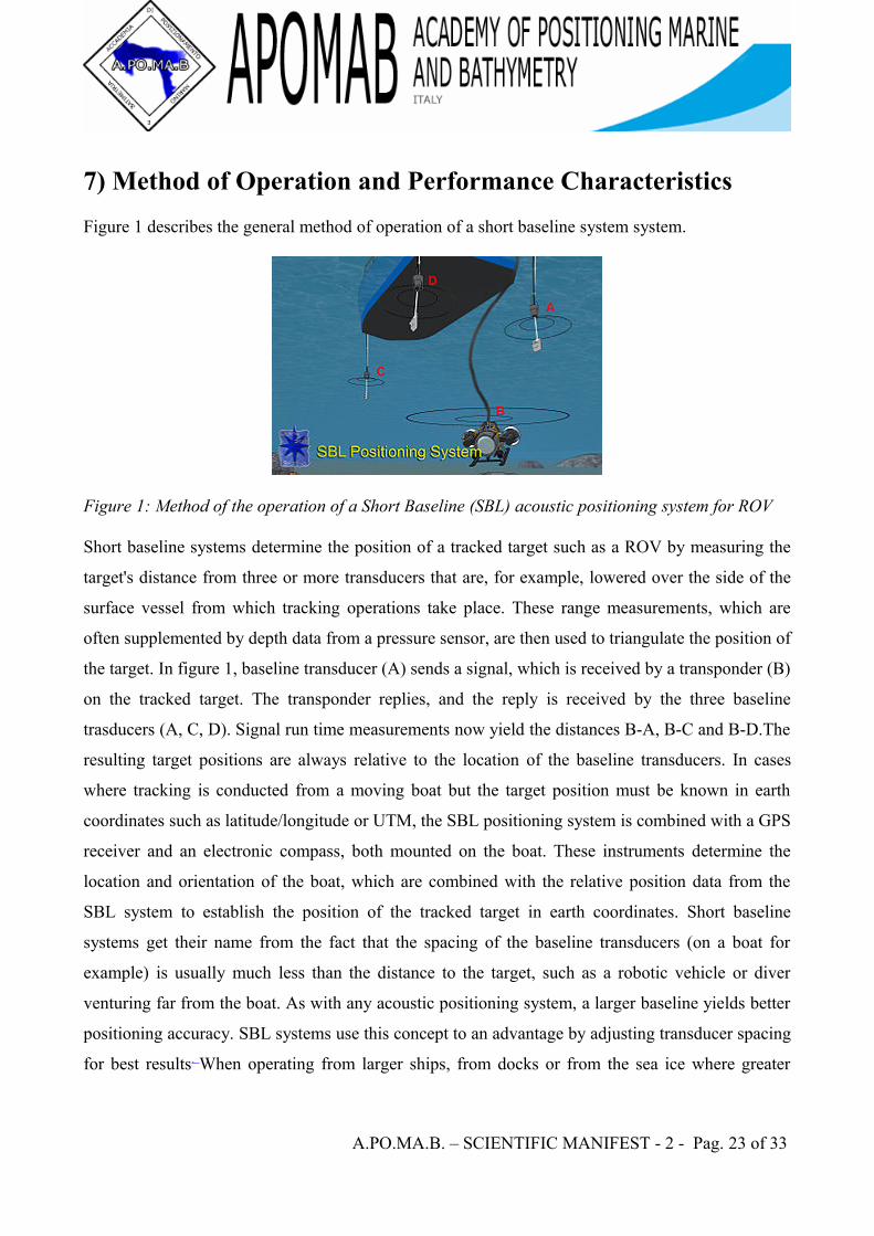
Figure 1: Method of the operation of a Short Baseline (SBL) acoustic positioning system for ROV
Short baseline systems determine the position of a tracked target such as a ROV by measuring the
target's distance from three or more transducers that are, for example, lowered over the side of the
surface vessel from which tracking operations take place. These range measurements, which are
often supplemented by depth data from a pressure sensor, are then used to triangulate the position of
the target. In figure 1, baseline transducer (A) sends a signal, which is received by a transponder (B)
on the tracked target. The transponder replies, and the reply is received by the three baseline
trasducers (A, C, D). Signal run time measurements now yield the distances B-A, B-C and B-D.The
resulting target positions are always relative to the location of the baseline transducers. In cases
where tracking is conducted from a moving boat but the target position must be known in earth
coordinates such as latitude/longitude or UTM, the SBL positioning system is combined with a GPS
receiver and an electronic compass, both mounted on the boat. These instruments determine the
location and orientation of the boat, which are combined with the relative position data from the
SBL system to establish the position of the tracked target in earth coordinates. Short baseline
systems get their name from the fact that the spacing of the baseline transducers (on a boat for
example) is usually much less than the distance to the target, such as a robotic vehicle or diver
venturing far from the boat. As with any acoustic positioning system, a larger baseline yields better
positioning accuracy. SBL systems use this concept to an advantage by adjusting transducer spacing
for best results. When operating from larger ships, from docks or from the sea ice where greater
A.PO.MA.B. – SCIENTIFIC MANIFEST - 2 - Pag. 23 of 33

transducer spacing can be used, SBL systems can yield a positioning accuracy and robustness
approaching that of sea-floor mounted LBL systems.
A.PO.MA.B. – SCIENTIFIC MANIFEST - 2 - Pag. 24 of 33
8) History and Examples of UseSBL systems are found employed in a variety of often specialized applications. Perhaps the first
implementation of any underwater acoustic positioning system was a SBL system installed on the
U.S. Navy oceanographic vessel USNS Mizar. In 1963, this system guided the bathyscape Trieste 1
to the wreck site of the American nuclear submarine USS Thresher. However, performance was still
so poor that out of ten search dives by Trieste 1, visual contact was only made once with the
wreckage.
The Woods Hole Oceanographic Institution is using a SHARPS SBL system to guide their JASON
tethered deep ocean robotic vehicle relative to the MEDEA depressor weight and docking station
associated with the vehicle. Rather than tracking both vehicles with a positioning system from the
surface which would result in degraded accuracy as the pair's deployment distance , the SBL
baseline transducers are mounted on MEDEA. yielding the position of JASON relative to MEDEA
with good accuracy independent of the system's deployment depth. The reported accuracy is 0.09m
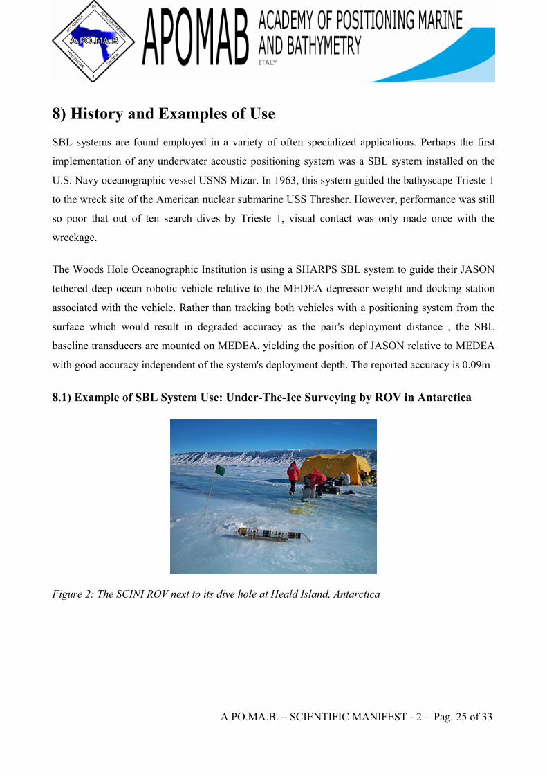
8.1) Example of SBL System Use: Under-The-Ice Surveying by ROV in Antarctica
Figure 2: The SCINI ROV next to its dive hole at Heald Island, Antarctica
A.PO.MA.B. – SCIENTIFIC MANIFEST - 2 - Pag. 25 of 33
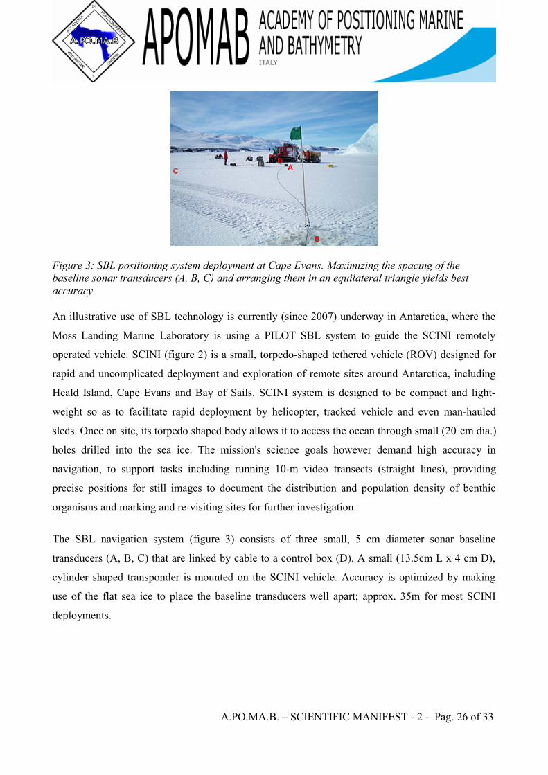
Figure 3: SBL positioning system deployment at Cape Evans. Maximizing the spacing of the baseline sonar transducers (A, B, C) and arranging them in an equilateral triangle yields best accuracy
An illustrative use of SBL technology is currently (since 2007) underway in Antarctica, where the
Moss Landing Marine Laboratory is using a PILOT SBL system to guide the SCINI remotely
operated vehicle. SCINI (figure 2) is a small, torpedo-shaped tethered vehicle (ROV) designed for
rapid and uncomplicated deployment and exploration of remote sites around Antarctica, including
Heald Island, Cape Evans and Bay of Sails. SCINI system is designed to be compact and light-
weight so as to facilitate rapid deployment by helicopter, tracked vehicle and even man-hauled
sleds. Once on site, its torpedo shaped body allows it to access the ocean through small (20 cm dia.)
holes drilled into the sea ice. The mission's science goals however demand high accuracy in
navigation, to support tasks including running 10-m video transects (straight lines), providing
precise positions for still images to document the distribution and population density of benthic
organisms and marking and re-visiting sites for further investigation.
The SBL navigation system (figure 3) consists of three small, 5 cm diameter sonar baseline
transducers (A, B, C) that are linked by cable to a control box (D). A small (13.5cm L x 4 cm D),
cylinder shaped transponder is mounted on the SCINI vehicle. Accuracy is optimized by making
use of the flat sea ice to place the baseline transducers well apart; approx. 35m for most SCINI
deployments.
A.PO.MA.B. – SCIENTIFIC MANIFEST - 2 - Pag. 26 of 33
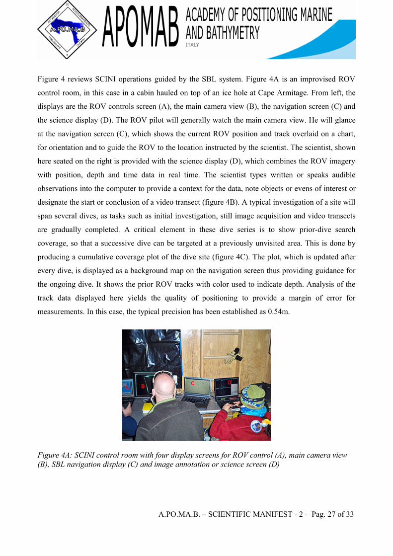
Figure 4 reviews SCINI operations guided by the SBL system. Figure 4A is an improvised ROV
control room, in this case in a cabin hauled on top of an ice hole at Cape Armitage. From left, the
displays are the ROV controls screen (A), the main camera view (B), the navigation screen (C) and
the science display (D). The ROV pilot will generally watch the main camera view. He will glance
at the navigation screen (C), which shows the current ROV position and track overlaid on a chart,
for orientation and to guide the ROV to the location instructed by the scientist. The scientist, shown
here seated on the right is provided with the science display (D), which combines the ROV imagery
with position, depth and time data in real time. The scientist types written or speaks audible
observations into the computer to provide a context for the data, note objects or evens of interest or
designate the start or conclusion of a video transect (figure 4B). A typical investigation of a site will
span several dives, as tasks such as initial investigation, still image acquisition and video transects
are gradually completed. A critical element in these dive series is to show prior-dive search
coverage, so that a successive dive can be targeted at a previously unvisited area. This is done by
producing a cumulative coverage plot of the dive site (figure 4C). The plot, which is updated after
every dive, is displayed as a background map on the navigation screen thus providing guidance for
the ongoing dive. It shows the prior ROV tracks with color used to indicate depth. Analysis of the
track data displayed here yields the quality of positioning to provide a margin of error for
measurements. In this case, the typical precision has been established as 0.54m.
Figure 4A: SCINI control room with four display screens for ROV control (A), main camera view (B), SBL navigation display (C) and image annotation or science screen (D)
A.PO.MA.B. – SCIENTIFIC MANIFEST - 2 - Pag. 27 of 33
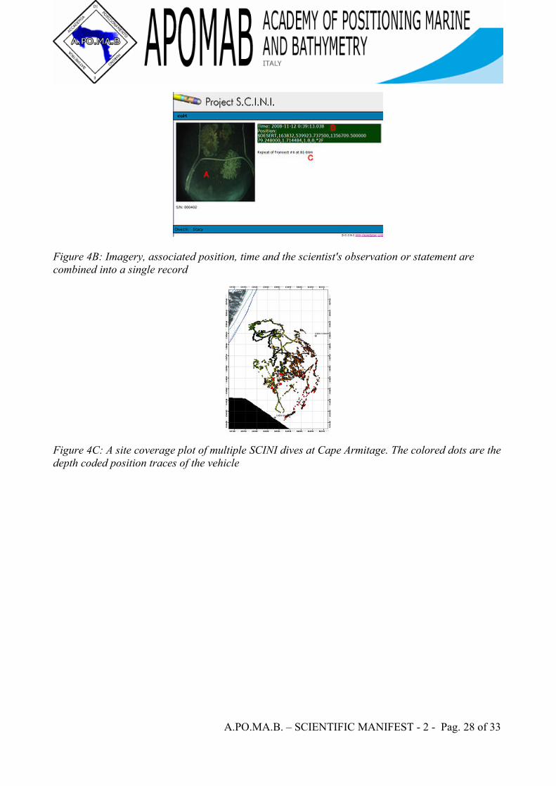
Figure 4B: Imagery, associated position, time and the scientist's observation or statement are combined into a single record
Figure 4C: A site coverage plot of multiple SCINI dives at Cape Armitage. The colored dots are the depth coded position traces of the vehicle
A.PO.MA.B. – SCIENTIFIC MANIFEST - 2 - Pag. 28 of 33
GPS Intelligent Buoys
GPS Intelligent Buoy (GIB) systems may be classified as inverted LBL devices where the
transducers are installed on GPS equipped sonobuoys that are either drifting or moored.GIBs may
be used in conjunction with an active underwater device (such as a pinger equipped torpedo), or
with a passive acoustic sound source (such as an inert bomb striking the surface of the water).
Typically the sound source or impact event is tracked or localized using a time of arrival (TOA)
technique.Typically several GIBs are deployed over a given area of operation; with the total number
determined by the size of the test area and the accuracy of the results desired. Different methods of
GPS positioning may be used for positioning the array of GIBs, with accuracies of cm to meter
level in realtime possible.
The system in patent protected and products are manufactured by the French company ACSA-
underwater-GPS (subsidiary of the ALCEN group). Three off-the shelf products are available from
the small portable GIB-Lite system to the large torpeado tracking GIB-FT, and including the
medium-size,medium-range GIB-Plus system.
9)History and Examples of UseUse of GIBs for underwater tracking and weapon scoring have been in use by the Navy since the
early to mid 1990’s. Early GIBs were created for broad ocean area weapons testing by modifying
conventional Navy sonobuoys with small OEM-grade GPS receivers and deploying them from a
helicopter or from P-3 Orion aircraft.The GPS data captured by the GIB was modulated over the
analog VHF acoustic data stream using frequency-shift keying (FSK). This allows the GPS
measurement data to be transmitted and received on legacy VHF sonobuoy receiver equipment. A
drifting array of twelve or more GIBs would be deployed in a concentric circular array
approximately 7 nm in diameter. Weapon strikes within the array emitted acoustic signatures that
were captured by the GIBs and transmitted up to the orbiting aircraft. Post-mission the GPS and
acoustic data from the GIBs would be combined to determine an absolute coordinate for the impact
location in WGS 84 coordinates.
A.PO.MA.B. – SCIENTIFIC MANIFEST - 2 - Pag. 29 of 33

Intentionally left blank
A.PO.MA.B. – SCIENTIFIC MANIFEST - 2 - Pag. 30 of 33
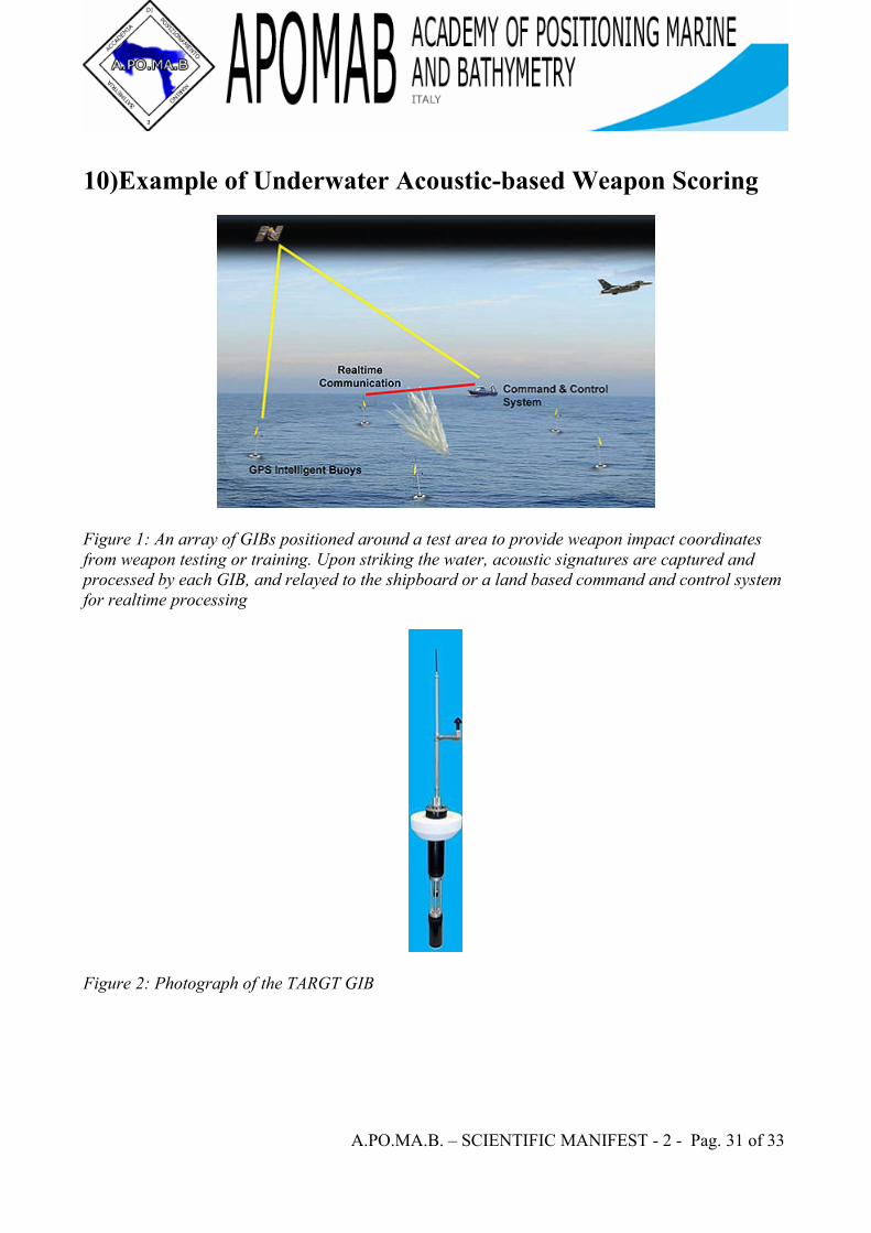
10)Example of Underwater Acoustic-based Weapon Scoring
Figure 1: An array of GIBs positioned around a test area to provide weapon impact coordinates from weapon testing or training. Upon striking the water, acoustic signatures are captured and processed by each GIB, and relayed to the shipboard or a land based command and control system for realtime processing
Figure 2: Photograph of the TARGT GIB
A.PO.MA.B. – SCIENTIFIC MANIFEST - 2 - Pag. 31 of 33

GIB type systems have been developed for a variety of specialized applications. An illustrative use
of GIBs for underwater positioning is the TARGT weapon scoring and training system.
The system concept (Figure 1) utilizes an array eight to ten GIBs (Figure 2) moored in a 2 km by 2
km array. In the case of the TARGT GIB, the GPS and RF antennas are located on top of the sensor
and the hydrophone, or underwater acoustic transducer, is located on the bottom. The device is
approximately 6 ft tall and weighs 35 lbs.
Inert weapon releases from military aircraft strike the surface of the water within the array, emitting
an acoustic signature that is captured by each of the GIBs. Each GIB determines the precise time of
the received signal and transmits this time to the deployment ship in near real time. A command and
control system located on the deployment and recovery ship combines the GPS data and acoustic
timing information to triangulate the impact location and determine the exact impact time in near
realtime. Several methods may be used, the most common being a time difference of arrival
(TDOA) least-squares solution algorithm. Post-mission data processing is performed to further
refine the results, with two-dimensional positioning accuracies of 1 to 2 meters and impact timing
accuracies of 1-2 milliseconds demonstrated.
A.PO.MA.B. – SCIENTIFIC MANIFEST - 2 - Pag. 32 of 33
References
• University of Rhode Island: Discovery of Sound in the Sea
• Underwater Acoustic Positioning Systems, P.H. Milne 1983, ISBN 0-87201-012-0
• The ROV Manual, Robert D. Christ and Robert L. Wernli Sr 2007, pages 96-103, ISBN 978-0-7506-8148-3
• Milne, chapters 3-5
• Christ and Wernli, sections 4.2.6-4.2.7
• MIT Deepwater Archaeology Research Group
• B.P. Foley and D.A. Mindell, "Precision Survey and Archaeological Methodology in Deep Water," ENALIA The Journal of the Hellenic Institute of Marine Archaeology, Vol. VI, 49-56, 2002
• Milne, chapter 4
• Christ and Wernli, section 4.2.6.3
• Integrating Precision Relative Positioning Into JASON/MEDEA ROV Operations, Bingham et al., MTS Journal Spring 2006 (Volume 40, Number 1)
• Kayser, J.R., Cardoza, M.A., et. al., "Weapon Scoring Results from a GPS Acoustic Weapons Test and Training System", Institute of Navigation National Technical Meeting, San Diego, CA, 24-26 January 2005
• Cardoza, M.A., Kayser, J.R., & Wade, B. "Offshore Scoring of Precision Guided Munitions", Inside GNSS April 2006, pages 32-39
• Kayser, J.R., Cardoza, M.A., et. al., “Offshore Weapon Scoring Using Rapidly Deployed Realtime Acoustic Sensors”, 21st Annual NDIA Test and Evaluation Forum, Charlotte, SC, 24-26 March 2005.
• Milne, Chapter 2
• Christ and Wernle, page 96
• Milne, Chapter 3
• Christ and Wernli, section 4.2.1
• The Last Dive, National Geographic Magazine October 1999
• Flexible Acoustic Positioning System Architecture, Davis, MTS Dynamic Positioning Conference 2002
A.PO.MA.B. – SCIENTIFIC MANIFEST - 2 - Pag. 33 of 33
Related Documents