9.9 ULTRASONIC INSPECTION (UT)

Welcome message from author
This document is posted to help you gain knowledge. Please leave a comment to let me know what you think about it! Share it to your friends and learn new things together.
Transcript

9.9 ULTRASONIC INSPECTION (UT)
Gen Article 1RT Article 2Nil Article 3 UT Article 4 for weldsUT Article 5 for materialsPT Article 6MT Article 7ET Article 8Visual Article 9LT Article 10AE Article 11 (FRP) /Article 12 (Metallic) / Article 13 (Continuous)Qualif. Article 14ACFM Article 15
9.9 UT Testing
9.9.1 Ultrasonic Inspection System Calibration9.9.2 Surface Preparation9.9.3 Examination Coverage9.9.4 Straight Beam Examination9.9.5 Angle Beam Examination9.9.6 Automated Ultrasonic Testing (AUT)9.9.7 Discontinuity Evaluation and Sizing
9.9 ULTRASONIC INSPECTION (UT)
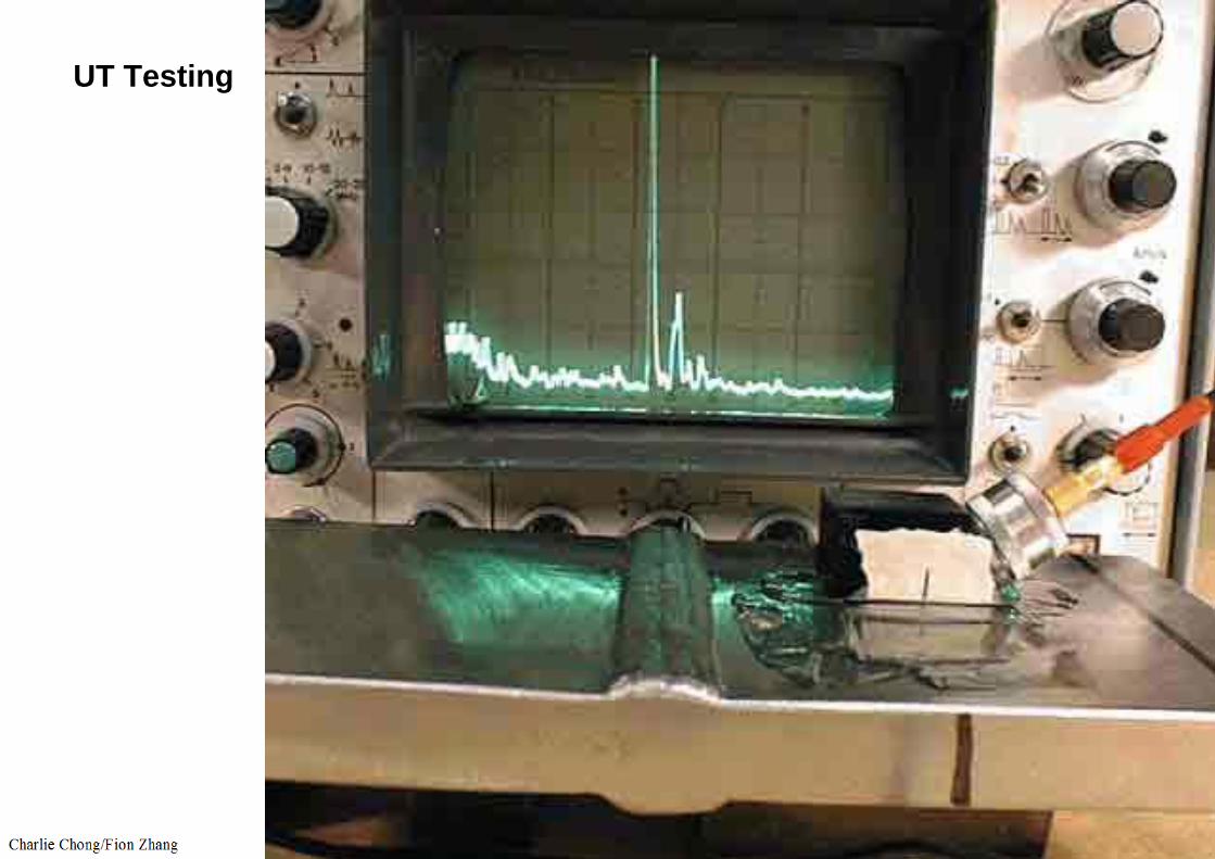
UT is capable of detecting surface and subsurface discontinuities. A beam of sound in the ultrasonic frequency range (>20,000 cycles per second) travels a straight line through the metal and reflects from an interface. For weld inspection, this high frequency sound beam is introduced into the weld and heat affected zone on a predictable path, which, upon reflection back from an interruption in material continuity, produces a wave that is electronically amplified to produce images. These images are displayed such that they might give the inspector size and positional information of the discontinuity.
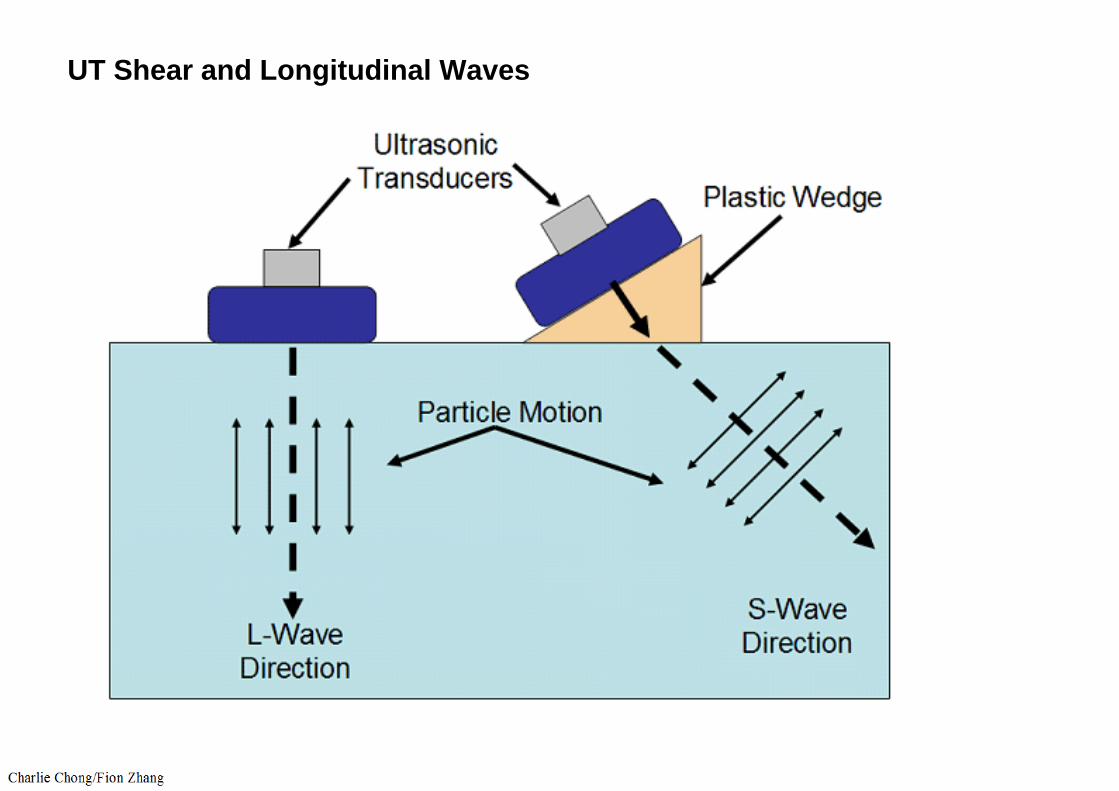
UT Shear and Longitudinal Waves

UT
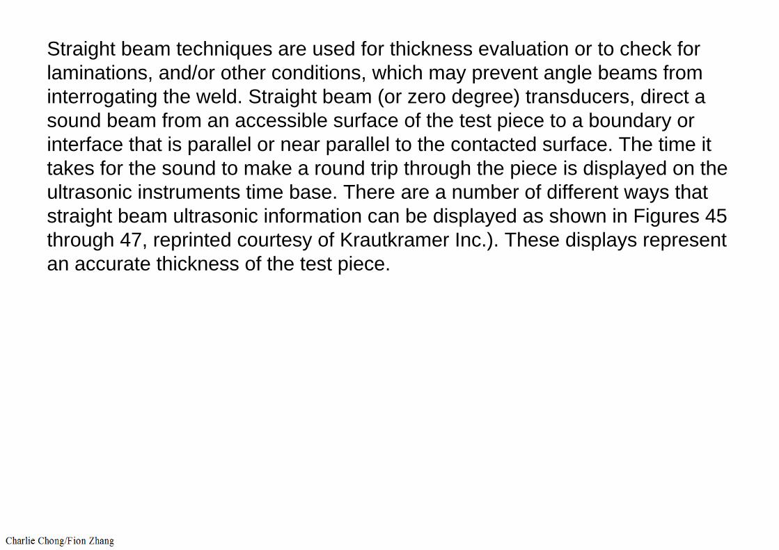
Straight beam techniques are used for thickness evaluation or to check for laminations, and/or other conditions, which may prevent angle beams from interrogating the weld. Straight beam (or zero degree) transducers, direct a sound beam from an accessible surface of the test piece to a boundary or interface that is parallel or near parallel to the contacted surface. The time it takes for the sound to make a round trip through the piece is displayed on the ultrasonic instruments time base. There are a number of different ways that straight beam ultrasonic information can be displayed as shown in Figures 45 through 47, reprinted courtesy of Krautkramer Inc.). These displays represent an accurate thickness of the test piece.

Figure 45—A-scan

Straight beam UT
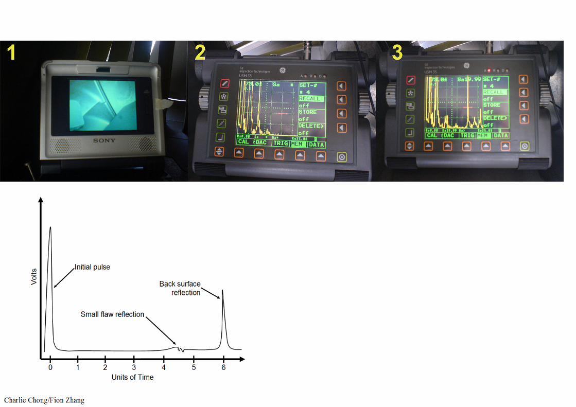
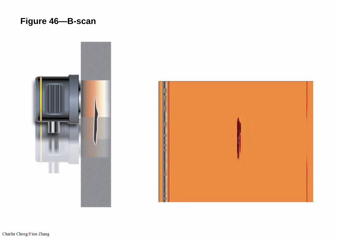
Figure 46—B-scan
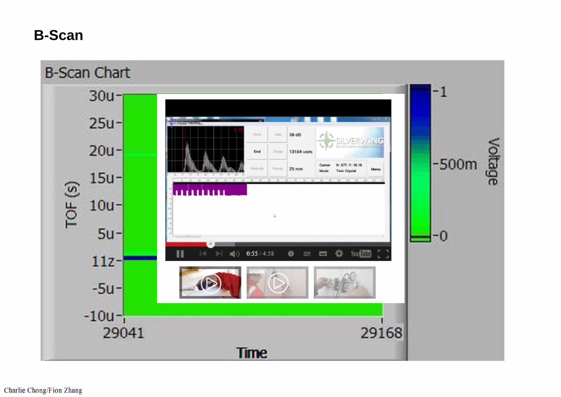
B-Scan
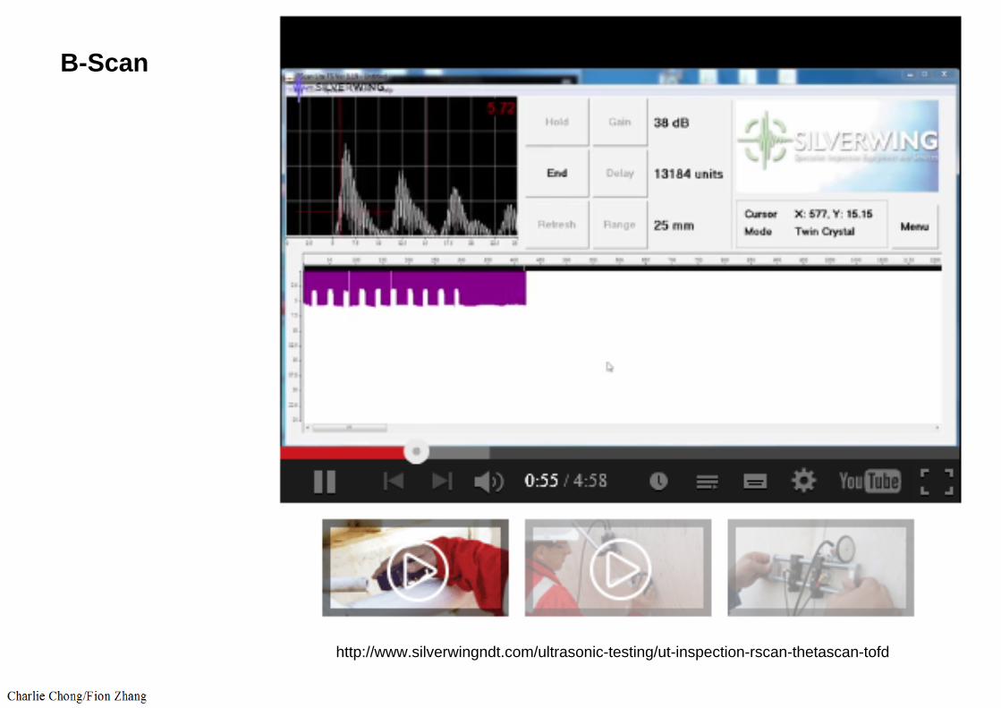
B-Scan
http://www.silverwingndt.com/ultrasonic-testing/ut-inspection-rscan-thetascan-tofd
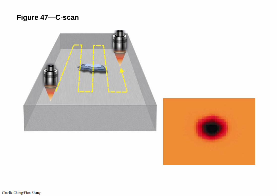
Figure 47—C-scan
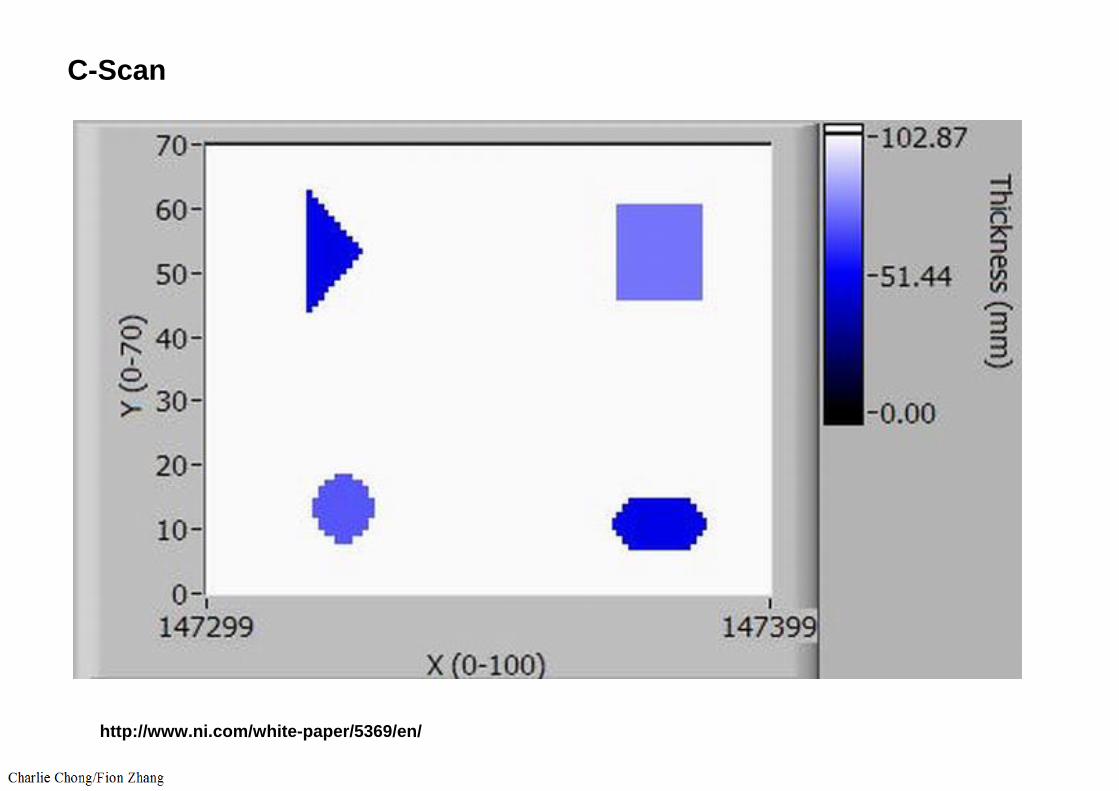
C-Scan
http://www.ni.com/white-paper/5369/en/
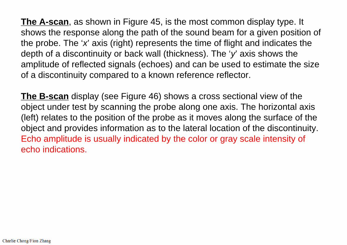
The A-scan, as shown in Figure 45, is the most common display type. It shows the response along the path of the sound beam for a given position of the probe. The ‘x’ axis (right) represents the time of flight and indicates the depth of a discontinuity or back wall (thickness). The ‘y’ axis shows the amplitude of reflected signals (echoes) and can be used to estimate the size of a discontinuity compared to a known reference reflector.
The B-scan display (see Figure 46) shows a cross sectional view of the object under test by scanning the probe along one axis. The horizontal axis (left) relates to the position of the probe as it moves along the surface of the object and provides information as to the lateral location of the discontinuity. Echo amplitude is usually indicated by the color or gray scale intensity of echo indications.
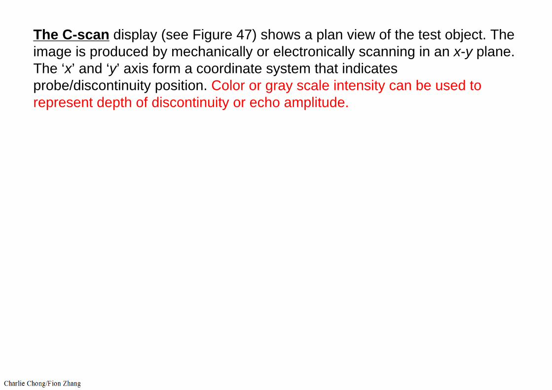
The C-scan display (see Figure 47) shows a plan view of the test object. The image is produced by mechanically or electronically scanning in an x-y plane. The ‘x’ and ‘y’ axis form a coordinate system that indicates probe/discontinuity position. Color or gray scale intensity can be used to represent depth of discontinuity or echo amplitude.
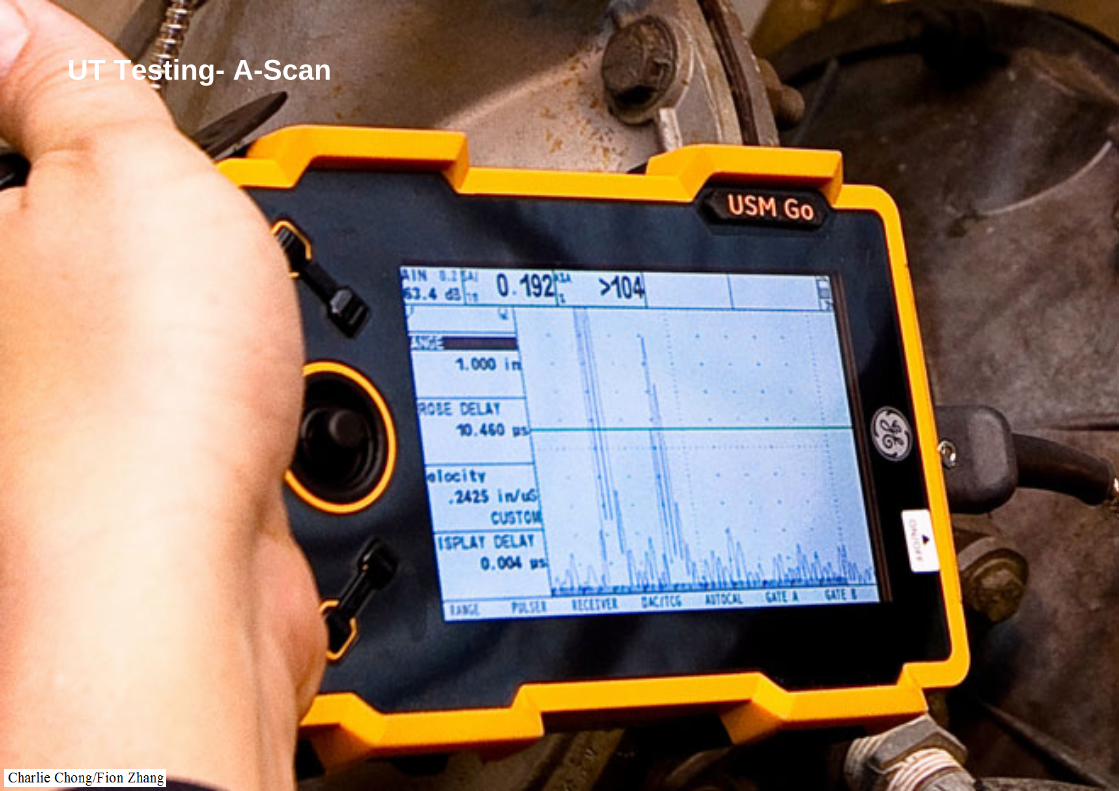
UT Testing- A-Scan
Shear wave or angle beam techniques are employed for identification of discontinuities in welds. The sound beam enters the area of the weld at an angle, it continues to propagate in a straight line or it will reflect from an interface such as a discontinuity. If the sound reflects from a discontinuity, aportion of the sound beam returns to the receiver where it is displayed on the ultrasonic instrument. These images can be displayed in a number of ways to aid in evaluation. From this display, information such as the size, location and type of discontinuity can be determined.
ASME Section V, Article 4, lists the general requirements for ultrasonic examination. Codes and specifications may list compliance with these requirements as mandatory. ASME B31.3 and ASME Section VIII, Division 1, requires ultrasonic examination be performed in accordance with Article 4.
Article 4 requires a written procedure be followed, and some of the requirements to be included in the procedure are:
a. Weld, base metal types, and configurations to be examined.b. Technique (straight or angle beam).c. Couplant type.d. Ultrasonic instrument type.e. Instrument linearity requirements.f. Description of calibration.g. Calibration block material and design.h. Inspection surface preparation.i. Scanning requirements (parallel and perpendicular to the weld).j. Scanning techniques (manual or automated).k. Evaluation requirements.l. Data to be recorded.m. Reporting of indications in terms of the acceptance standards of the
referencing code.n. Post examination cleaning.
9.9.1 Ultrasonic Inspection System Calibration
Ultrasonic inspection system calibration is the process of adjusting the controls of the ultrasonic instrument such that the UT display of the sound path is linear. Calibration is to ensure that there is sufficient sensitivity to detect discontinuity of the size and type expected in the product form and process. The inspection system includes the examiner, the ultrasonic instrument, cabling, the search unit, including wedges or shoes, couplant, and a reference standard. The search unit transducer should be of a size, frequency, and angle that is capable of detecting the smallest rejectable defect expected to be in the part being examined. The ultrasonic instrument isrequired to meet or exceed the requirements of ASME Section V, Article 5, Paragraph T-530, and should provide the functionality required to produce the required display of both the calibration reflectors and any discontinuities located during the examination.
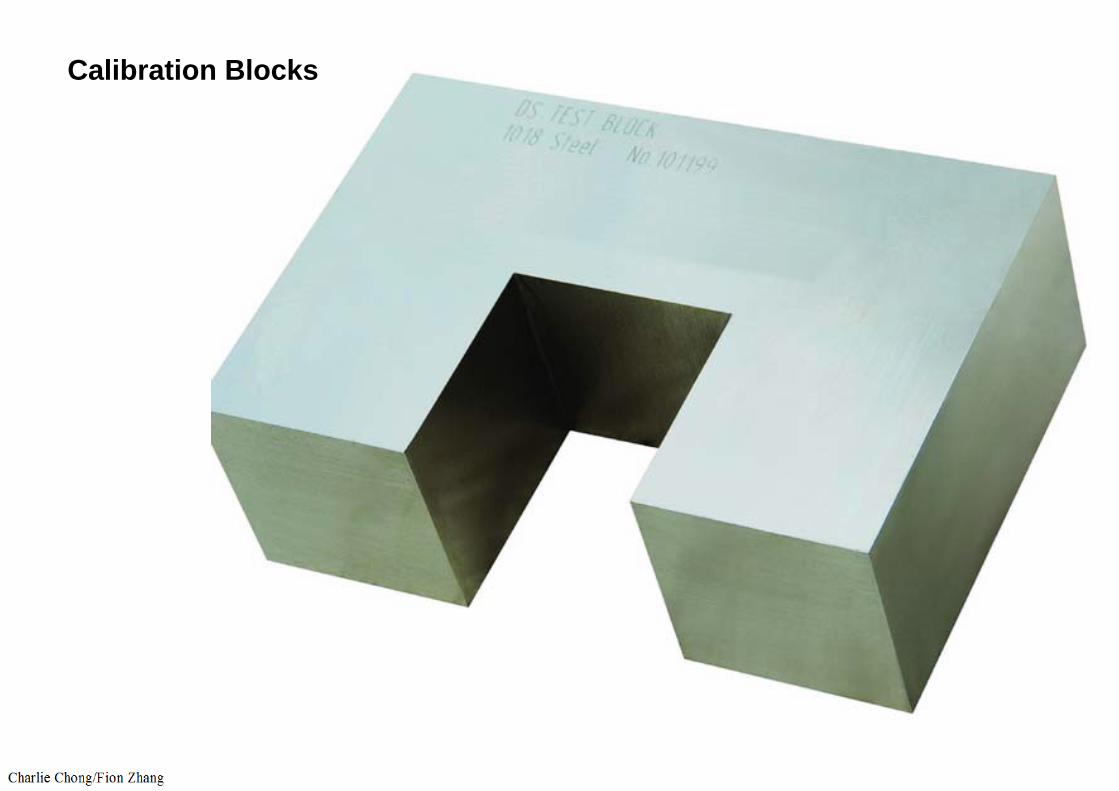
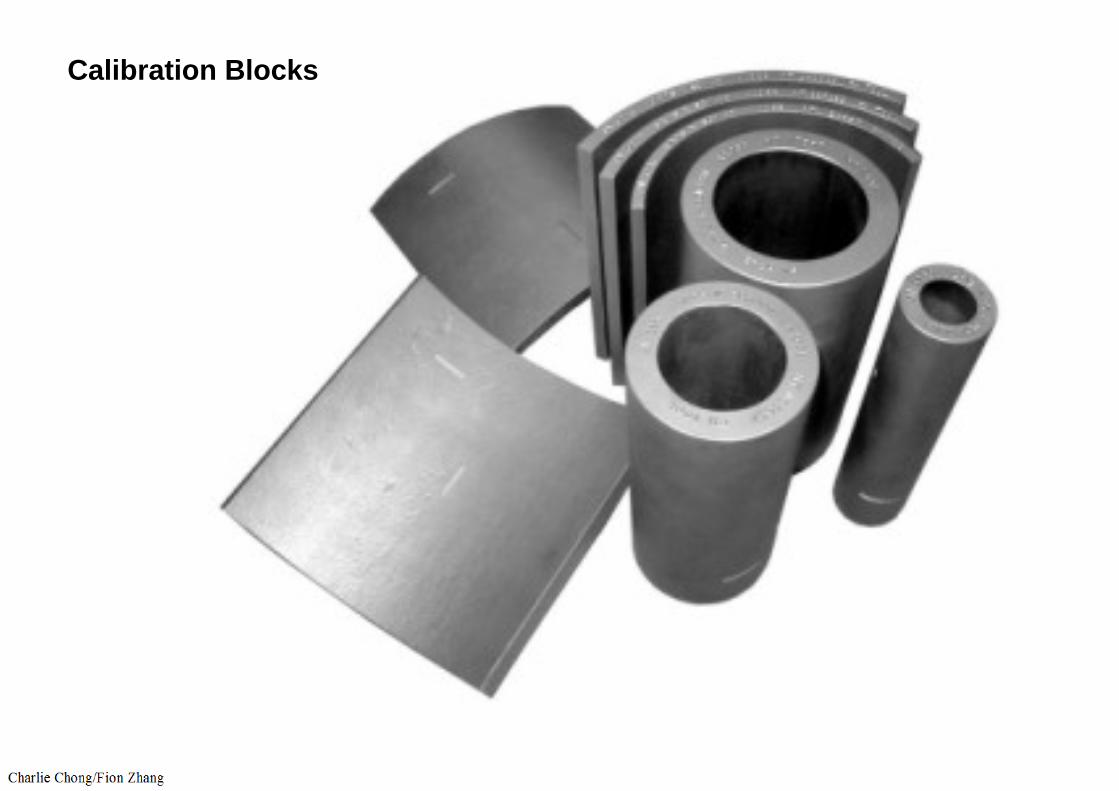
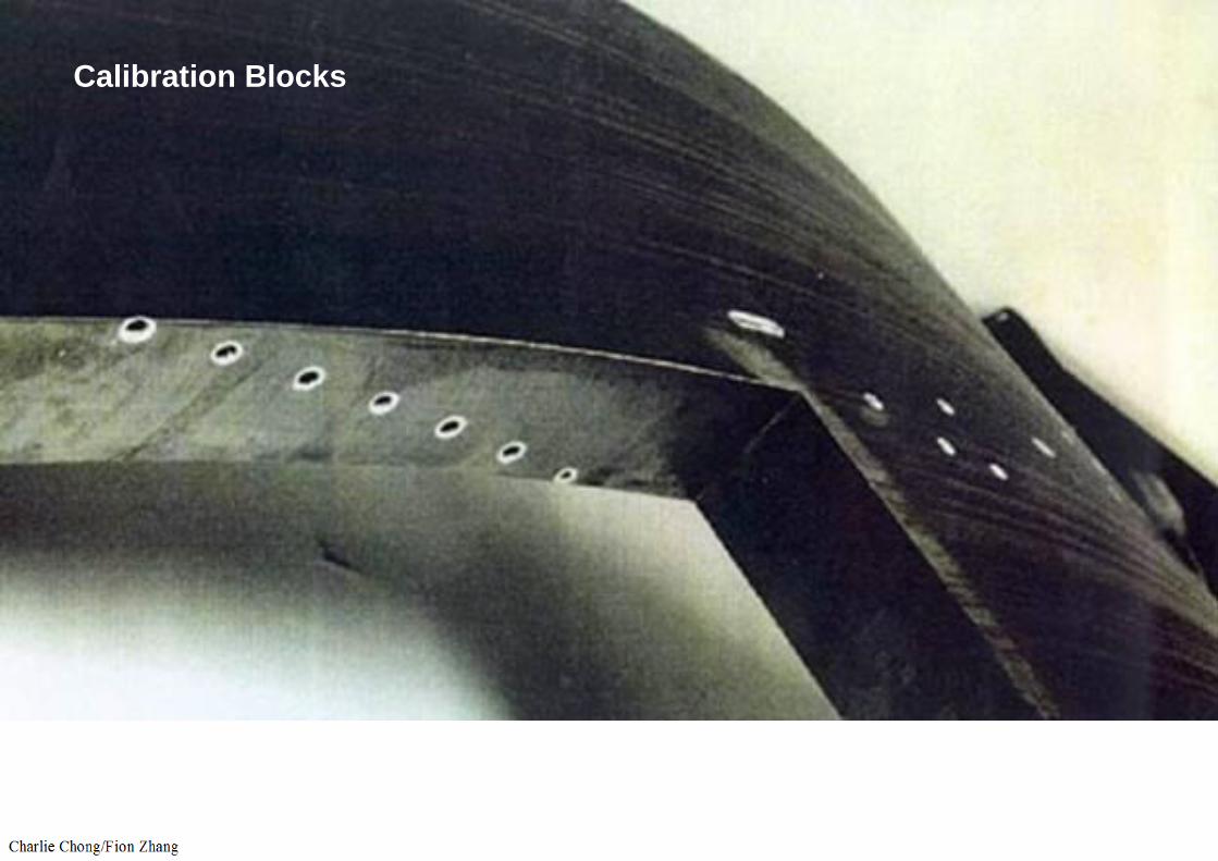
The reference standard (calibration block) should be of the same;
1. nominal diameter and 2. thickness, 3. composition and 4. heat treatment condition as the product that is being examined. \5. It should also have the same surface condition as the part being examined.
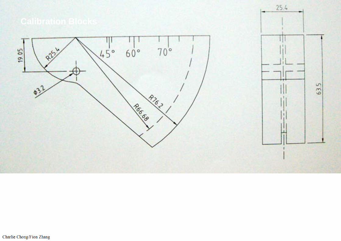
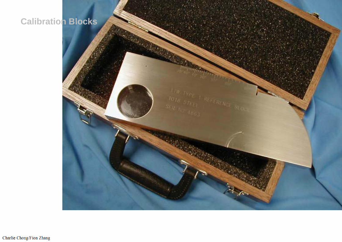
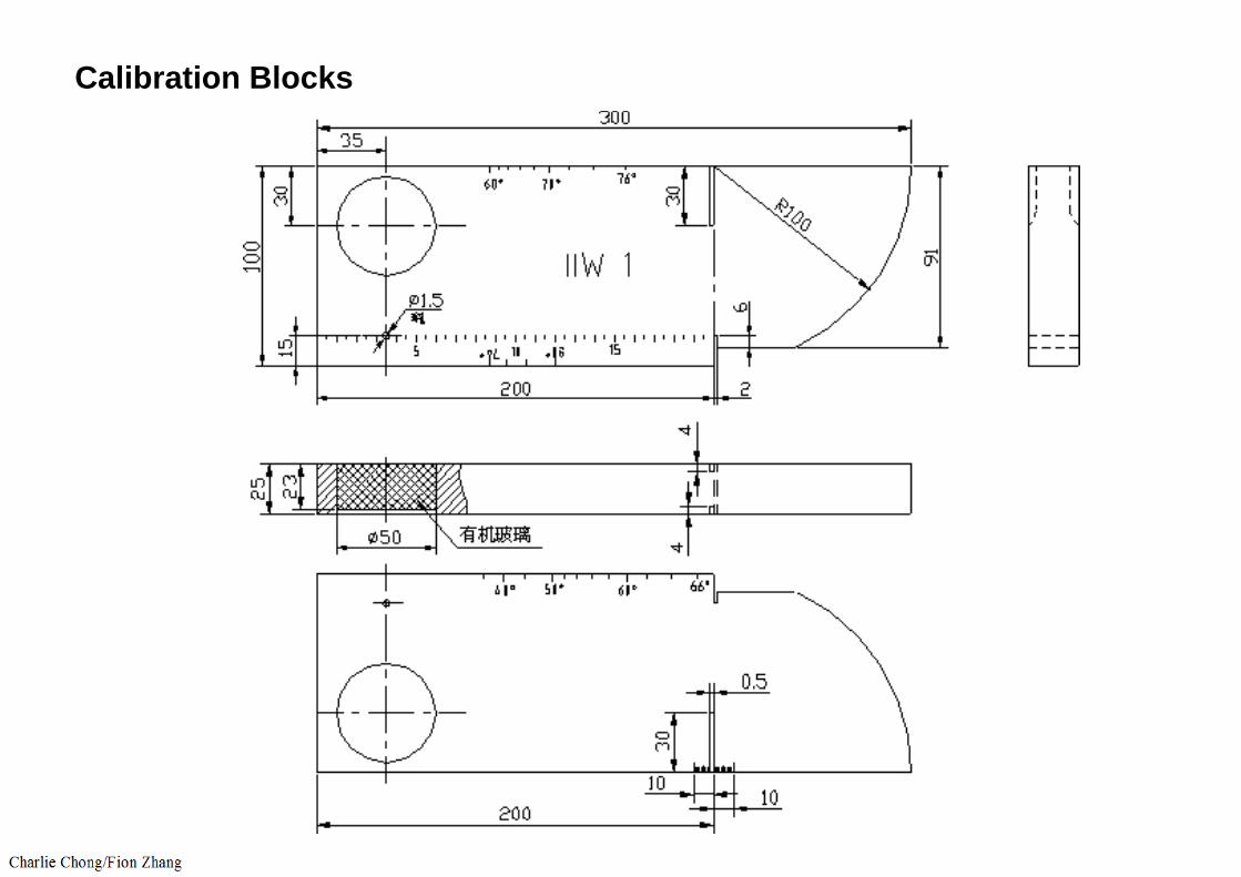
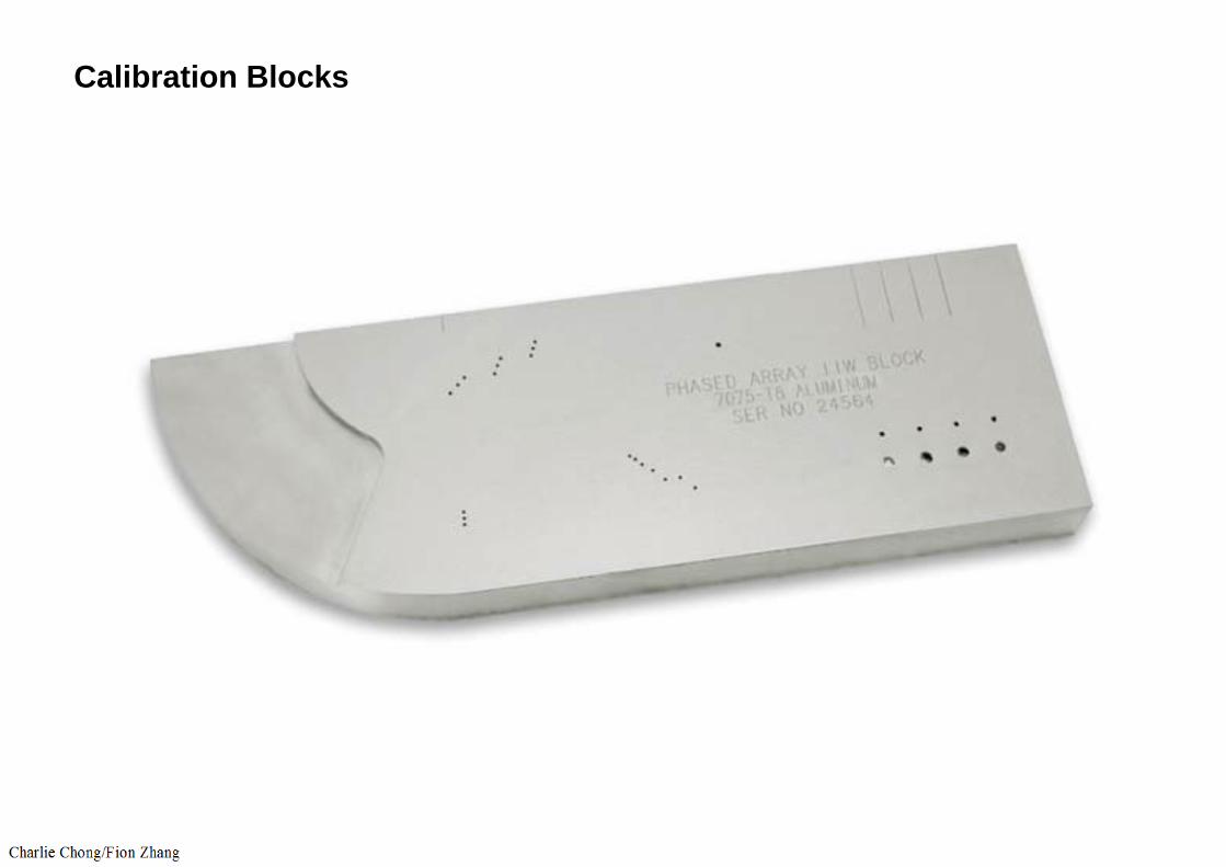
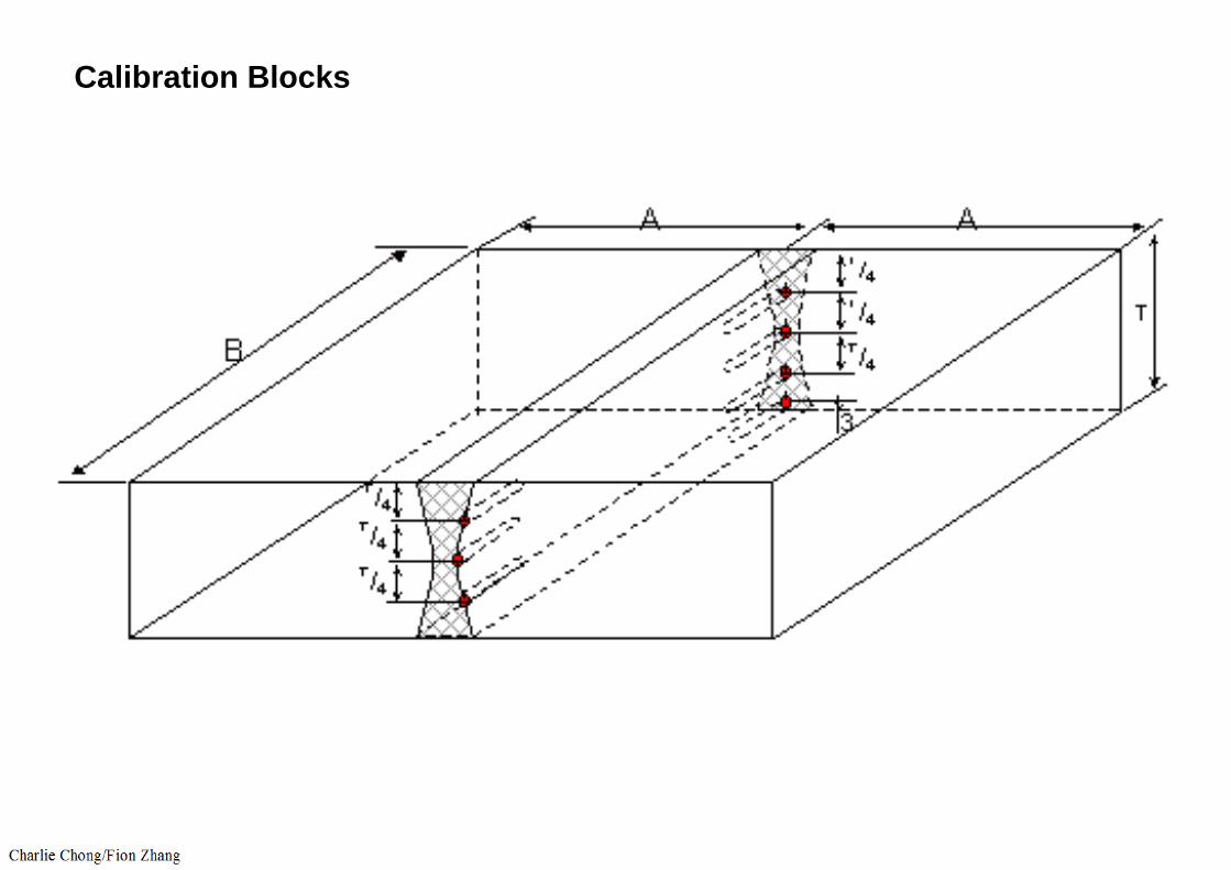
The reference standard should be of an acceptable size and have known reflectors of a specified size and location. These reflectors should be acceptable to the referencing code. ASME Section V, Article 5, Figures T-542.2.1 and T-542.8.1.1 details the requirements for basic calibration block construction.
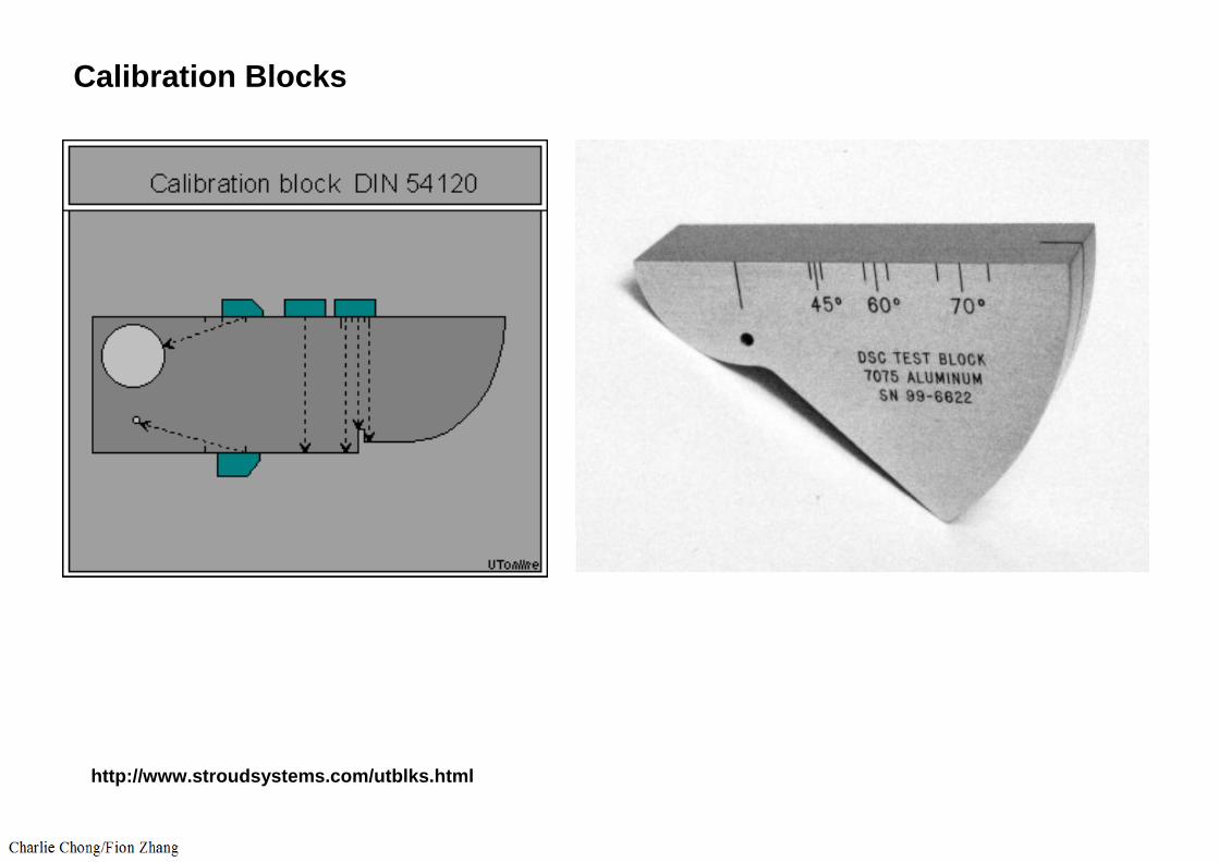
Calibration Blocks
http://www.stroudsystems.com/utblks.html

Calibration Blocks
Calibration Blocks
Calibration Blocks
Calibration Blocks

Calibration Blocks

Calibration Blocks
Calibration Blocks
Calibration Blocks
Calibration Blocks

Calibration Blocks
Calibration Blocks

Calibration Blocks

Calibration Blocks
UT Testing
Calibration Blocks
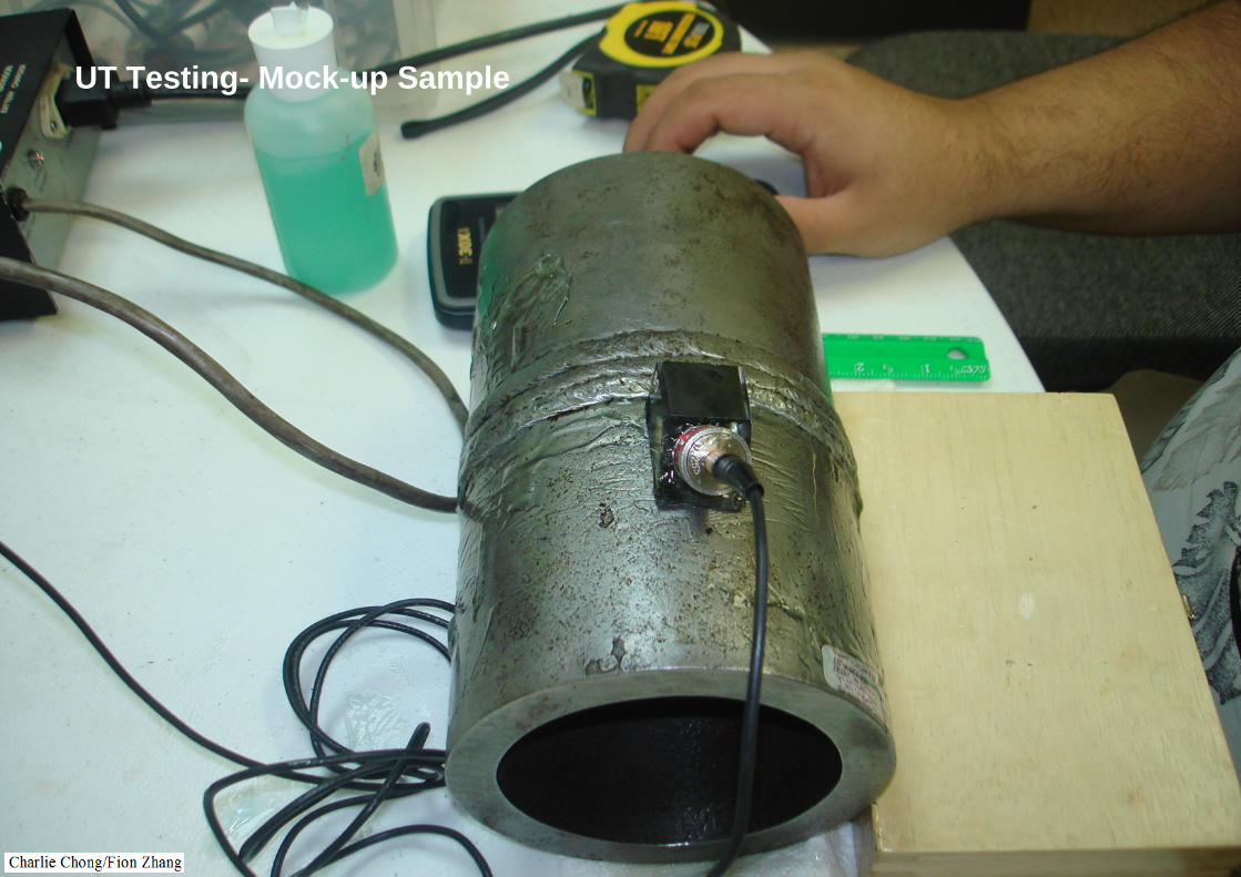
UT Testing- Mock-up Sample
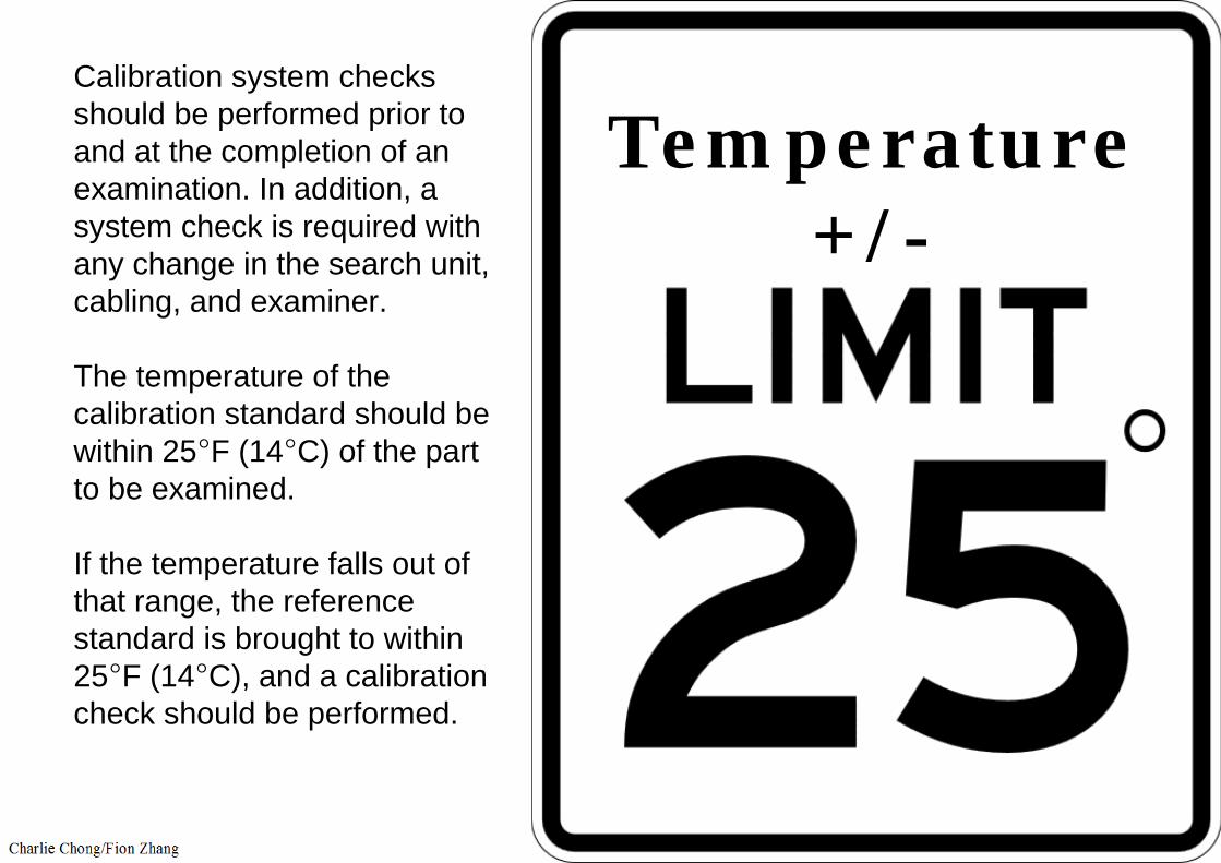
Calibration system checks should be performed prior to and at the completion of an examination. In addition, a system check is required with any change in the search unit, cabling, and examiner.
The temperature of the calibration standard should be within 25°F (14°C) of the part to be examined.
If the temperature falls out of that range, the reference standard is brought to within 25°F (14°C), and a calibration check should be performed.
Temperature+/-
For high temperature work, special high temperature
(1) transducers and (2) couplants are usually necessary.
Consideration should be given to the fact that temperature variations within the wedge or delay line can cause beam angle changes and/or alter the delayon the time base.

System checks are typically performed at a minimum of every four hours during the process of examination but can be done more often at the examiners discretion, when malfunctioning is suspected. If during a system calibration check, it is determined that the ultrasonic equipment is not functioning properly, all areas tested since the last successful calibration should be reexamined.
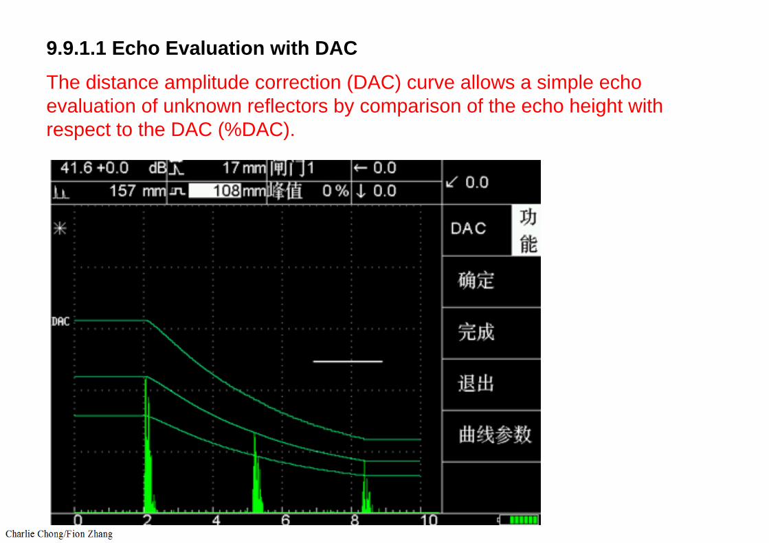
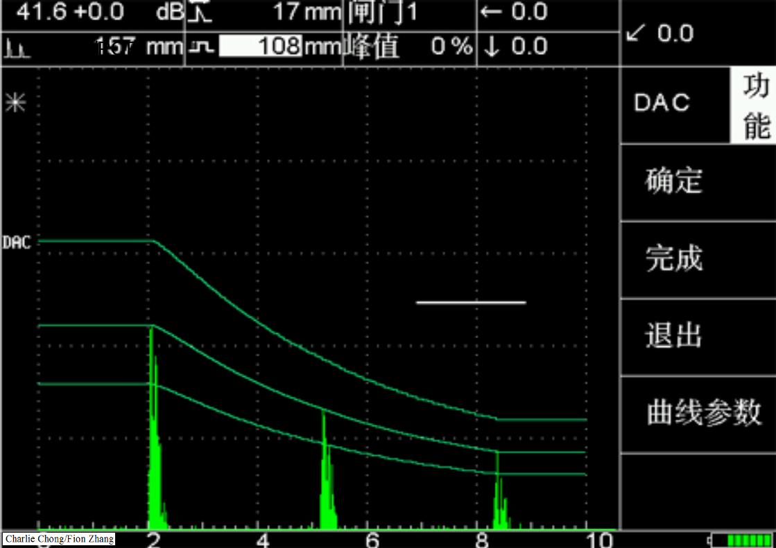
9.9.1.1 Echo Evaluation with DACThe distance amplitude correction (DAC) curve allows a simple echo evaluation of unknown reflectors by comparison of the echo height with respect to the DAC (%DAC).

9.9.1.1 Echo Evaluation with DACThe distance amplitude correction (DAC) curve allows a simple echo evaluation of unknown reflectors by comparison of the echo height with respect to the DAC (%DAC).
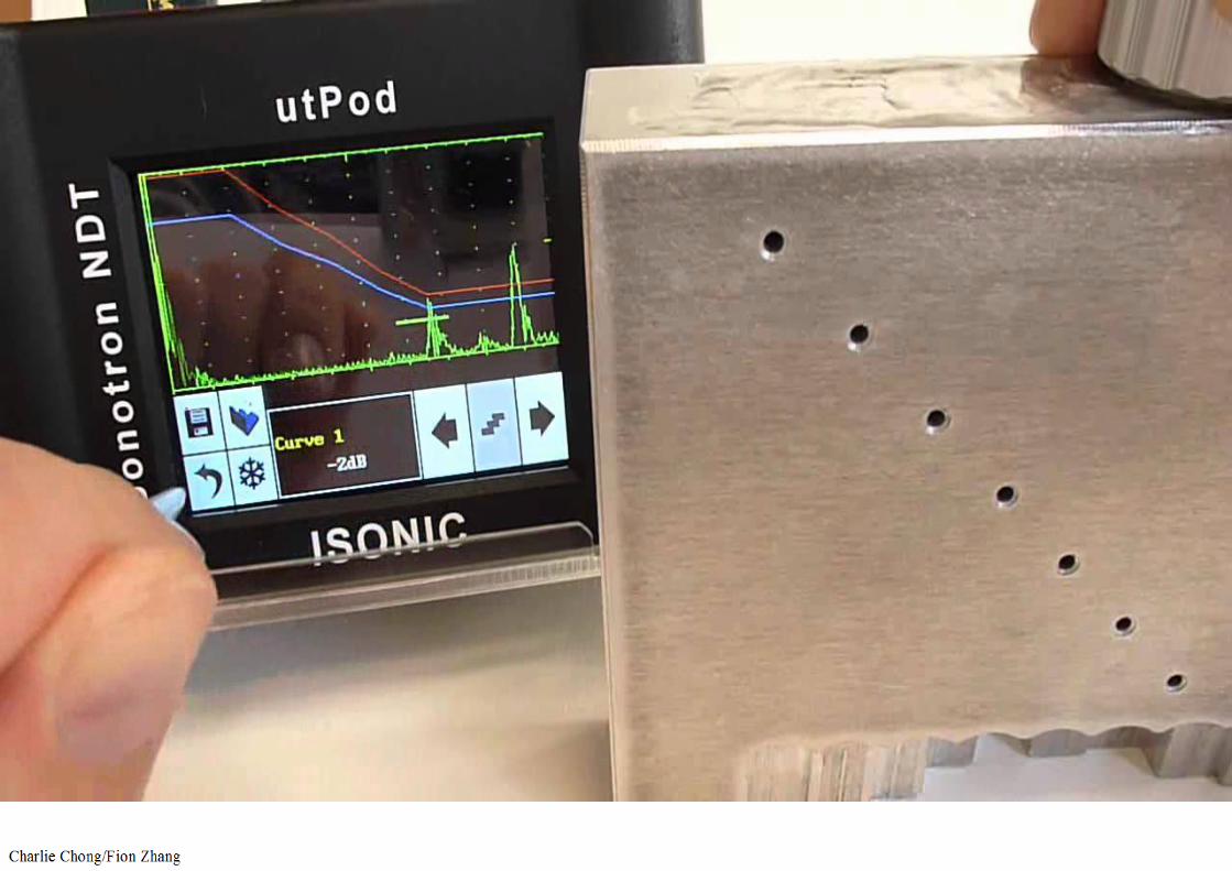
Because of attenuation and beam divergence in all materials, the echo amplitude from a given size reflector decreases as the distance from the probe increases. To set up a DAC, the maximum response from a specified reference reflector (e.g., flat bottom or side drilled hole) is recorded at different depths over the required test range. The calibration block with reference reflectors should be of the same material as the part under test. The curve is plotted through the peak points of the echo signals from the reflectors as shown in Figure 48. The curve represents the signal amplitude loss based upon distance, from the (1) same size reference reflector using a (2) given probe. The gain setting used to establish the DAC during the initial calibration is referred to as the primary reference level sensitivity. Evaluation is performed at this sensitivity level.

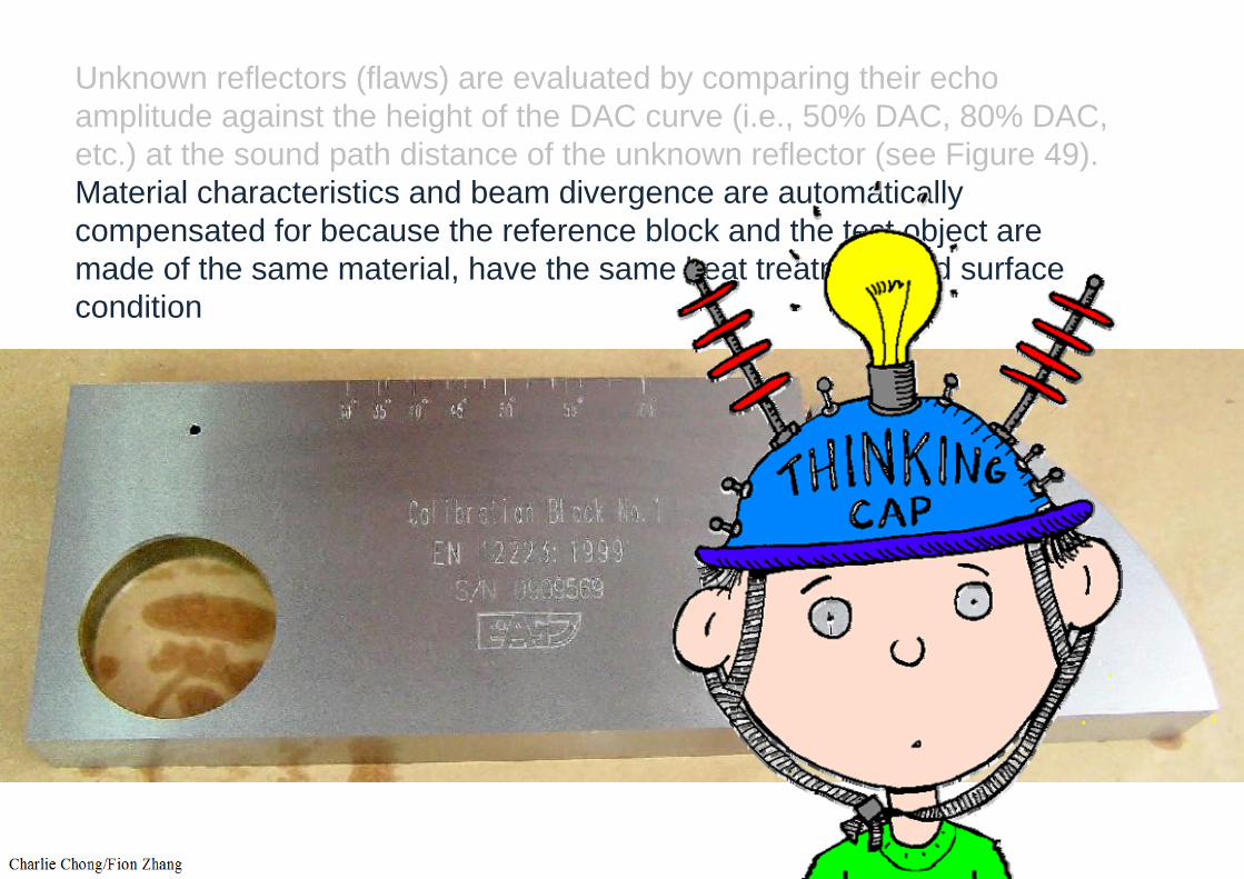
Unknown reflectors (flaws) are evaluated by comparing their echoamplitude against the height of the DAC curve (i.e., 50% DAC, 80% DAC, etc.) at the sound path distance of the unknown reflector (see Figure 49). Material characteristics and beam divergence are automatically compensated for because the reference block and the test object are made of the same material, have the same heat treatment and surface condition
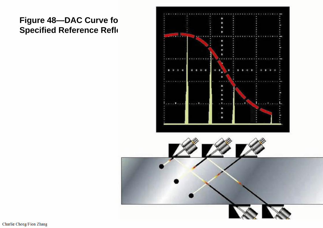
Figure 48—DAC Curve for a Specified Reference Reflector

http://www.youtube.com/watch?v=LvKK7-uyRc8

DAC Plots


DAC- Distance Amplitude Correction
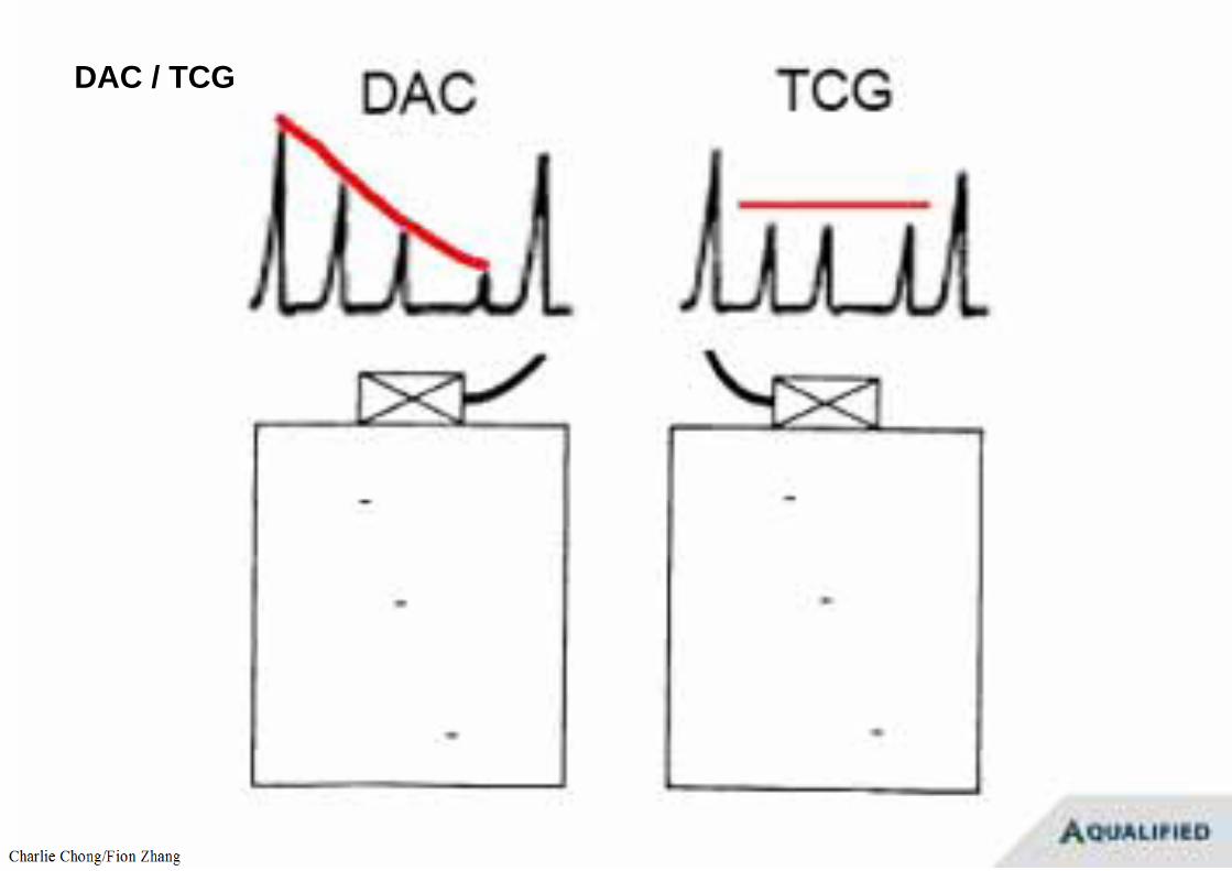
DAC / TCG
WPS/PQR


DAC Curve with a specific reflector/ probe combination at 24dB gain.http://www.ndt-ed.org/TeachingResources/NDT_Tips/DevelopingDAC.htm

Unknown reflectors (flaws) are evaluated by comparing their echoamplitude against the height of the DAC curve (i.e., 50% DAC, 80% DAC, etc.) at the sound path distance of the unknown reflector (see Figure 49). Material characteristics and beam divergence are automatically compensated for because the reference block and the test object are made of the same material, have the same heat treatment and surface condition
Unknown reflectors (flaws) are evaluated by comparing their echoamplitude against the height of the DAC curve (i.e., 50% DAC, 80% DAC, etc.) at the sound path distance of the unknown reflector (see Figure 49). Material characteristics and beam divergence are automatically compensated for because the reference block and the test object are made of the same material, have the same heat treatment and surface condition

Figure 49—DAC Curve for an Unknown Reflector
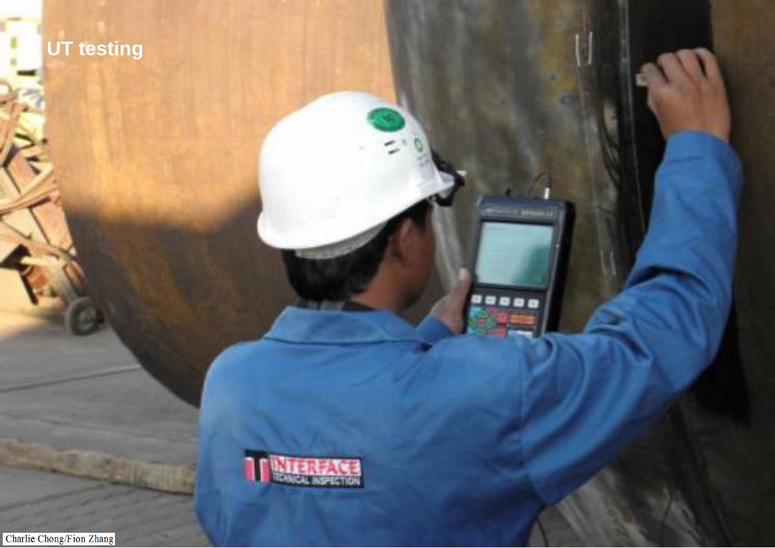
UT testing

Indications
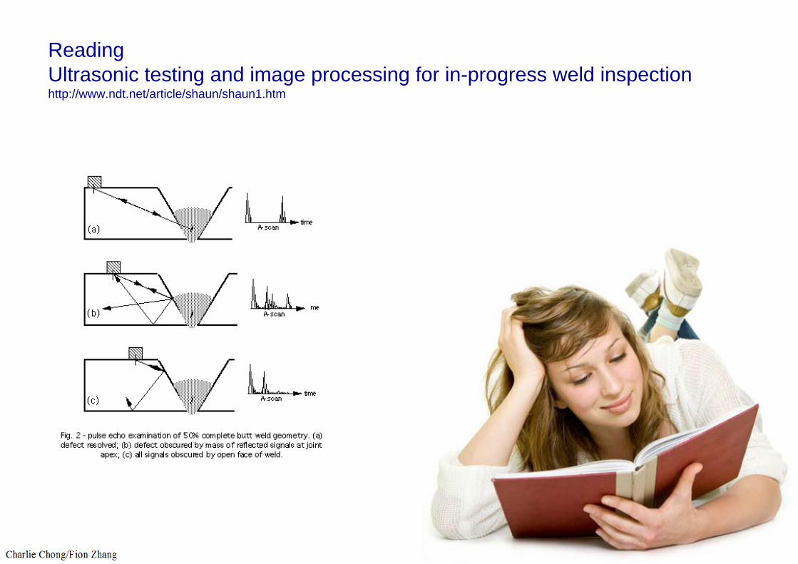
ReadingUltrasonic testing and image processing for in-progress weld inspectionhttp://www.ndt.net/article/shaun/shaun1.htm
9.9.2 Surface Preparation
Prior to UT examination, all scan surfaces should be free from weld spatter, surface irregularities and foreign matter that might interfere with the examination. The weld surface should be prepared such that it will permit a meaningful examination.
9.9.3 Examination Coverage
The volume of the weld and HAZ should be examined by moving the search unit over the examination surface so as to scan the entire examination volume. Each pass of the transducer will overlap the previous pass by 10% of the transducer element dimension. The rate of search unit movement will not exceed 6 in. (152 mm) per second unless the calibration was verified at an increased speed. In many cases, the search unit is angulated from side to side to increase the chances of detecting fine cracks that are oriented other than perpendicular to the sound beam.

Numbers to remember
Each pass of the transducer will overlap the previous pass by 10% of the transducer element dimension.
The rate of search unit movement will not exceed 6 in. (152 mm) per second unless the calibration was verified at an increased speed.
http://www.olympus-ims.com/en/ndt-tutorials/flaw-detection/common-test-practices/
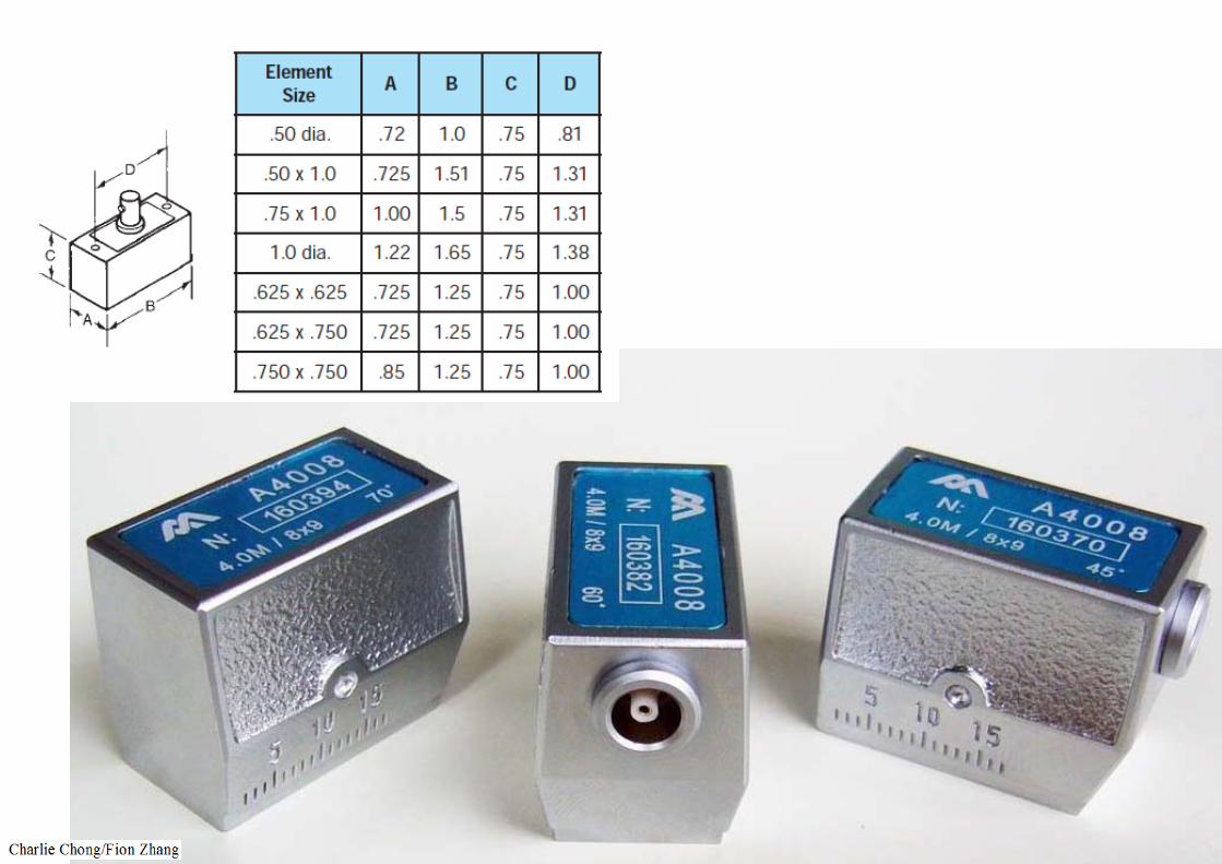
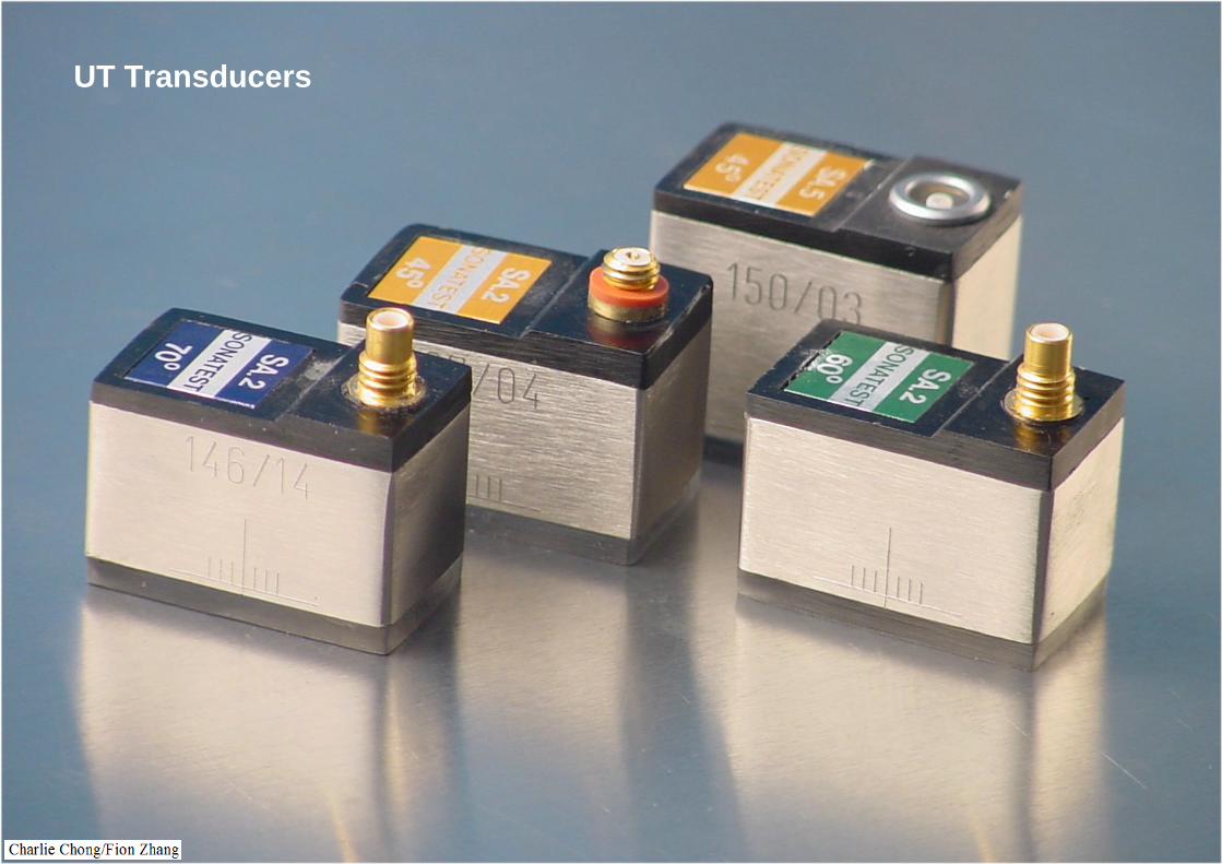
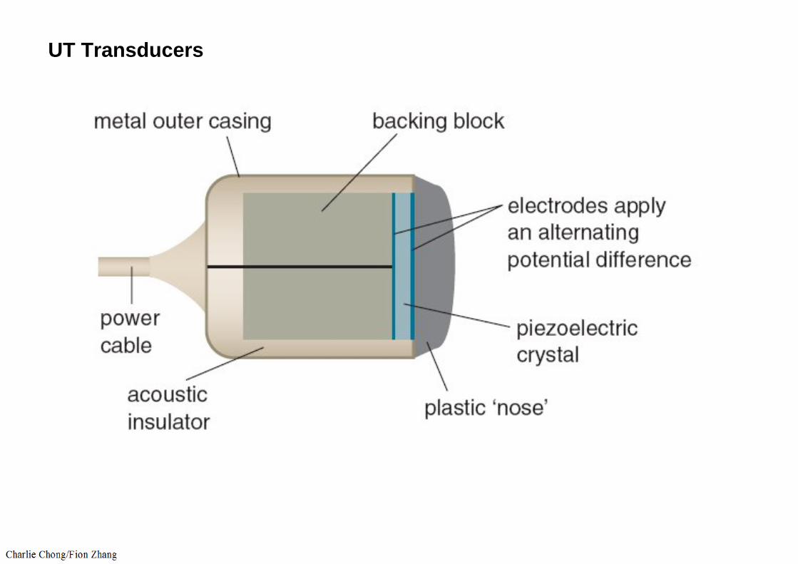
UT Transducers
UT Transducers

UT Transducers

UT Transducers

UT Transducers
10% scanning overlapped Min of the transducer element dimension.
6 inches / second scanning speed Max.

Angulations

9.9.4 Straight Beam Examination
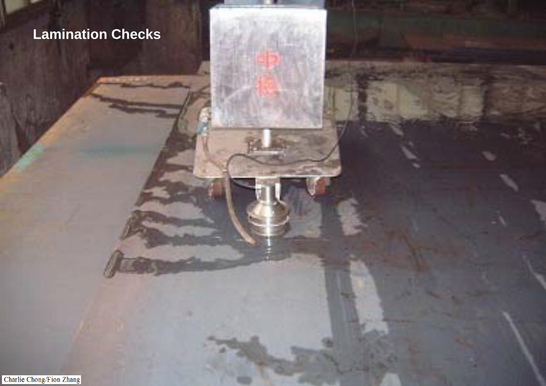
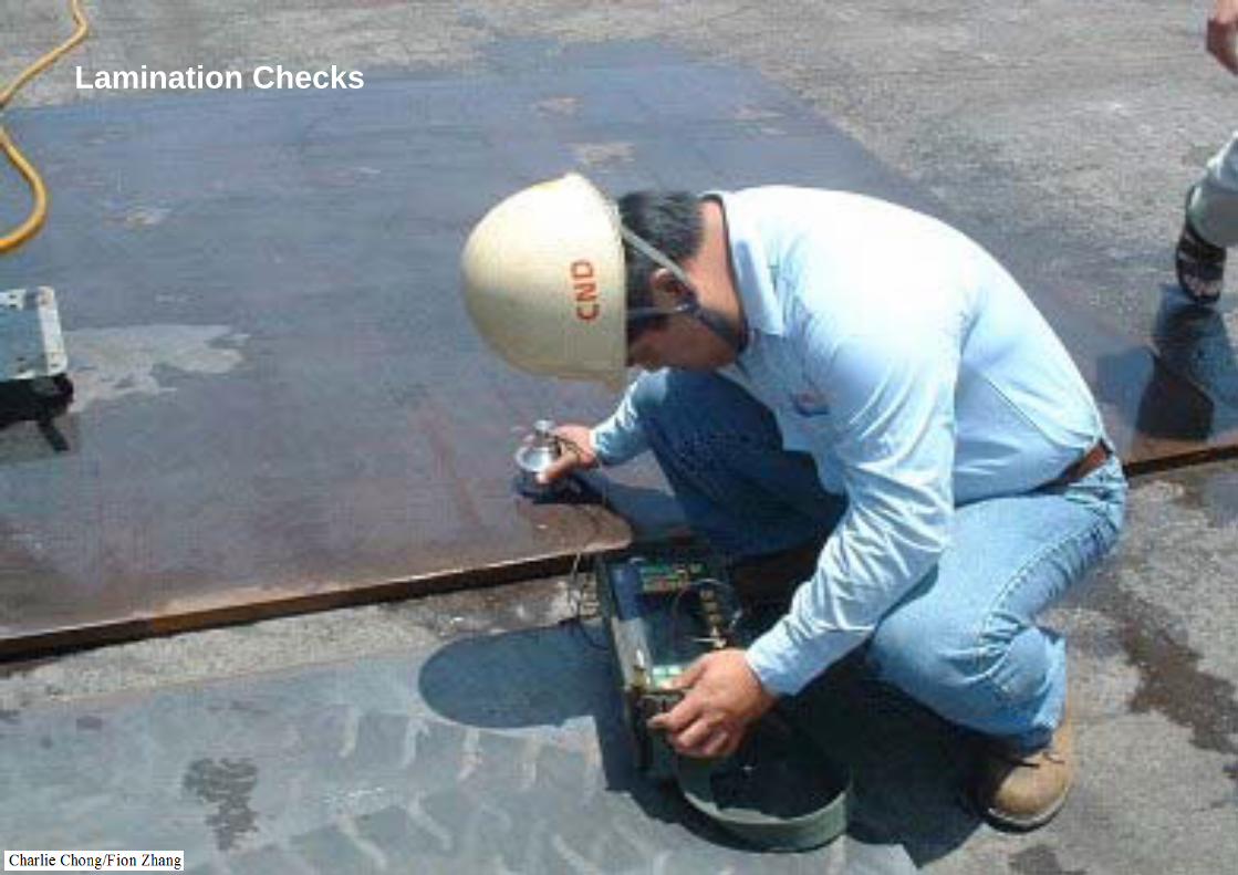
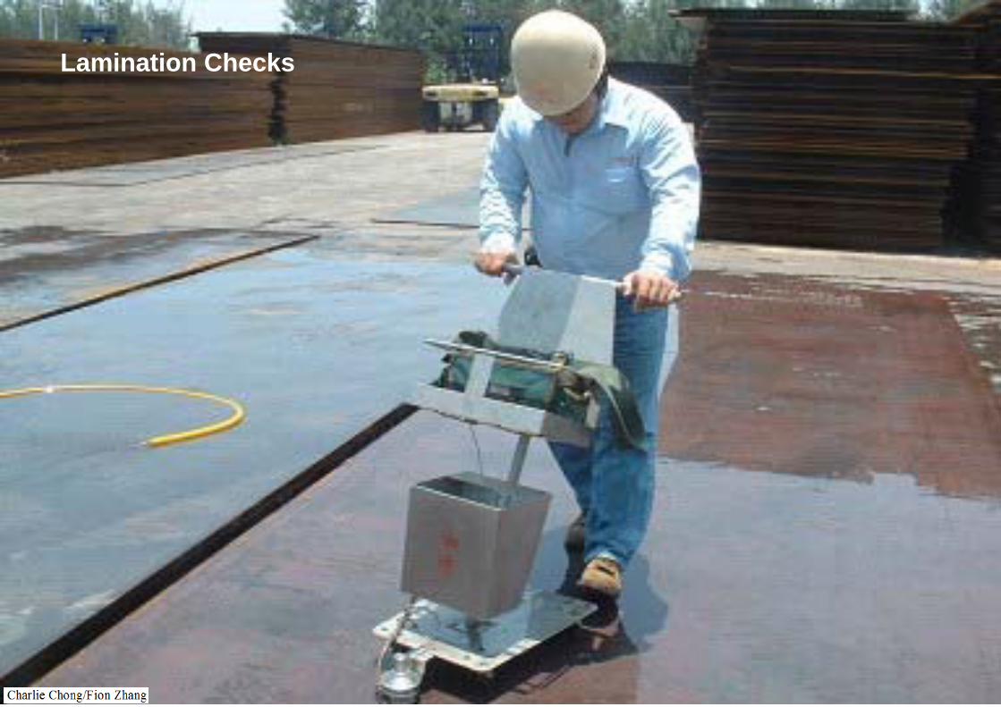
A straight beam examination should be performed adjacent to the weld to detect reflectors that would interfere with the angle beam from examining the weld such as a lamination in the base material. All areas having this type of reflector should be recorded.


Lamination Checkshttp://www.china-ndt.com.tw/new_page_29.htm

Plate lamination checks

Lamination Checks
Lamination Checks

Lamination Checks

Lamination Checks

Lamination Checks

Lamination Checks
Lamination Checks
Lamination Checks

UT Testing of WeldSkip = 2 x Thickness x Tan(60)Depth = Sound path x Cos(60)Distance = Sound path x Sin(60)
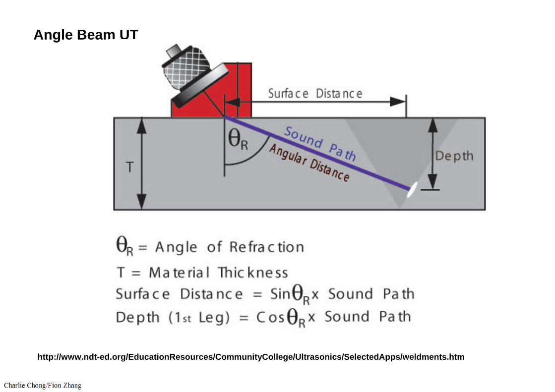
Angle Beam UT
http://www.ndt-ed.org/EducationResources/CommunityCollege/Ultrasonics/SelectedApps/weldments.htm

Skip = 2 x Thickness x Tan(60)

9.9.5 Angle Beam Examination
Typically, there are two different angle beam examinations performed on a weld.
A scan for reflectors that are oriented parallel to the weld, and A scan for reflectors that are oriented transverse to the weld.
In both cases, the scanning should be performed at a gain setting at least two times the reference level sensitivity established during calibration. (6dB)
Evaluation of indications however, should be performed at the primary reference level sensitivity. In both cases, the search unit should be manipulated such that the ultrasonic energy passes through the required volume of the weld and HAZ. During examination for reflectors that are oriented parallel to the weld, the sound beam is directed at approximate right angles to the weld, preferably from both sides of the weld. For reflectors that are oriented transverse to the weld, the sound beam is directed parallel to the weld and a scan is performed in one direction around the weld, then the search unit is turned 180° and another scan is performed until the ultrasonic energy passes through the required volume of weld and HAZ in twodirections.
Evaluation of indications however, should be performed at the primary reference level sensitivity. In both cases, the search unit should be manipulated such that the ultrasonic energy passes through the required volume of the weld and HAZ. During examination for reflectors that are oriented parallel to the weld, the sound beam is directed at approximate right angles to the weld, preferably from both sides of the weld. For reflectors that are oriented transverse to the weld, the sound beam is directed parallel to the weld and a scan is performed in one direction around the weld, then the search unit is turned 180° and another scan is performed until the ultrasonic energy passes through the required volume of weld and HAZ in two directions.
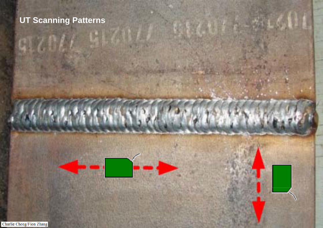
UT Scanning Patterns
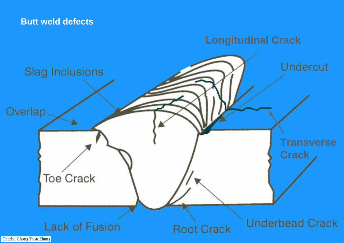
Butt weld defects
Transverse Crack
Longitudinal Crack
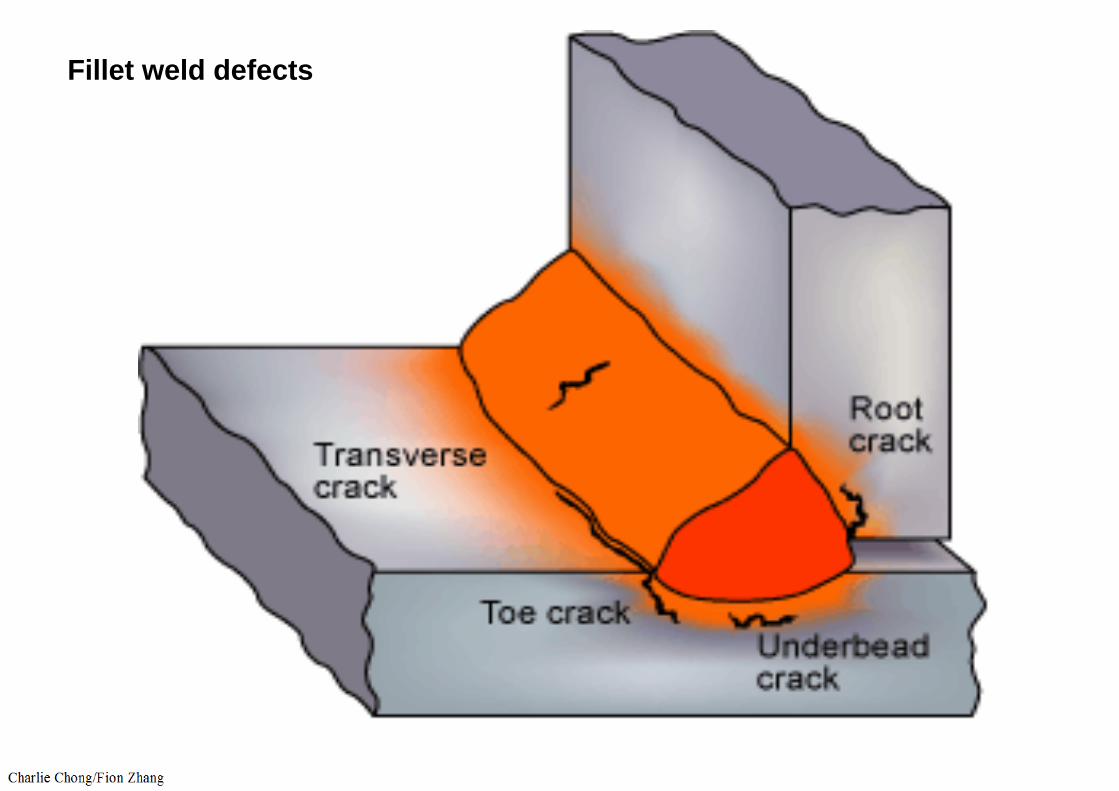
Fillet weld defects

9.9.6 Automated Ultrasonic Testing (AUT)
Volumetric Inspection of welds may be performed using one of the three automated ultrasonic weld inspection techniques:
a. Pulse Echo Raster Scanning: This technique inspects with zero degree compression and two angle beam transducers interrogating the weld from either side simultaneously. The compression transducers examine for corrosion or laminar defects in the base metal and the angle beam transducers scan the volume of the weld metal.
b. Pulse Echo Zoned Inspection: The zoned inspection is a Line Scantechnique. The technique uses an array of transducers on either side of the weld with the transducer angles and transit time gates set to ensure that the complete volume of the weld is inspected.
c. Time of Flight Diffraction (TOFD): This is a line scan technique used in the pitch-catch mode. The multi-mode transducers are used to obtain the maximum volume inspection of the weld region. More than one set of transducers may be required for a complete volumetric inspection.
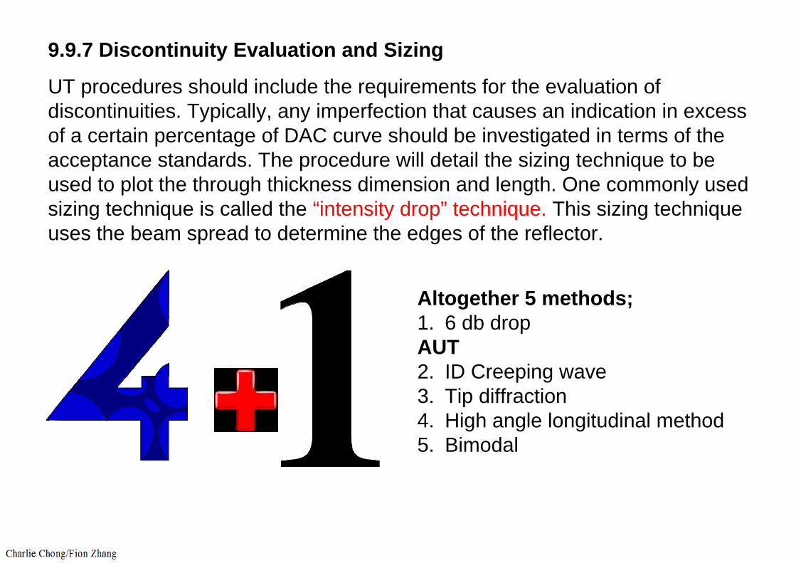
9.9.7 Discontinuity Evaluation and Sizing
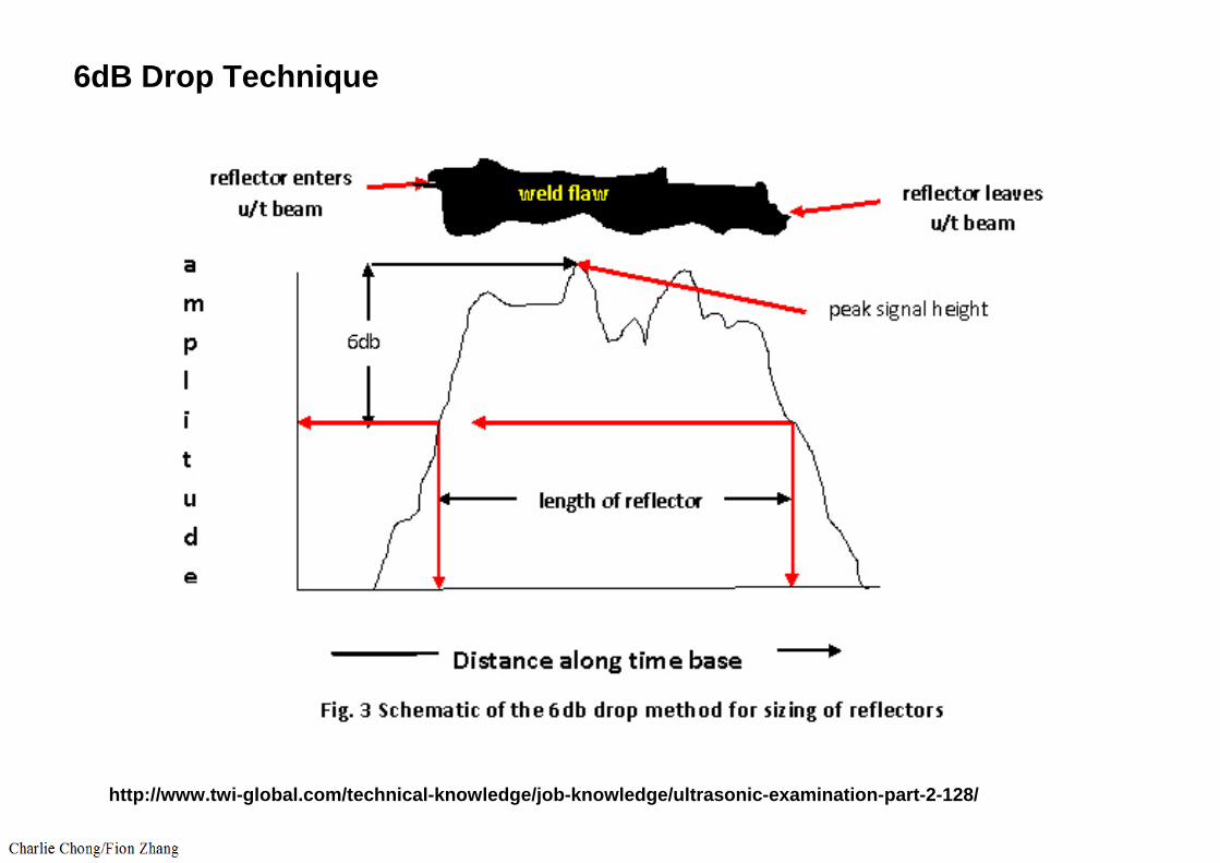
UT procedures should include the requirements for the evaluation of discontinuities. Typically, any imperfection that causes an indication in excess of a certain percentage of DAC curve should be investigated in terms of the acceptance standards. The procedure will detail the sizing technique to beused to plot the through thickness dimension and length. One commonly used sizing technique is called the “intensity drop” technique. This sizing technique uses the beam spread to determine the edges of the reflector.
Altogether 5 methods;1. 6 db dropAUT2. ID Creeping wave3. Tip diffraction4. High angle longitudinal method5. Bimodal

Altogether 5 methods;1. 6 db dropAUT2. ID Creeping wave3. Tip diffraction4. High angle longitudinal method5. Bimodal

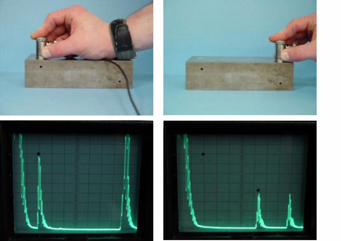
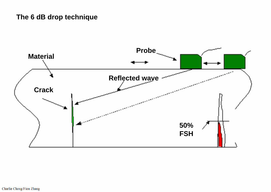
The 6 dB drop technique is commonly used to determine length of the reflector. Using this technique, the transducer is positioned on the part such that the amplitude from the reflector is maximized. This point is marked with a grease pencil. The UT instrument is adjusted to set the signal to 80% full screen height (FSH). The transducer is then moved laterally until the echo has dropped to 40% FSH (6dB). This position is also marked. The transducer is then moved laterally in the other direction, past the maximum amplitude point, until the echo response again reaches 40% FSH. This point is marked with the grease pencil. The two outside marks represent the linear dimensionof the reflector.
The intensity drop sizing technique can also be used to determine the through thickness of the reflector. However the transducer is moved forward and backwards from the reflector and the corresponding time base sweep position from the UT instrument is noted at each of the positions. This informationis then plotted to determine the discontinuity location with respect to the inside or outside diameter of the part being examined, and the through thickness dimension of the reflector.
Other through-thickness sizing techniques are described in 9.9.7.1 through 9.9.7.4.

Other through-thickness sizing techniques are described in 9.9.7.1 through 9.9.7.4.
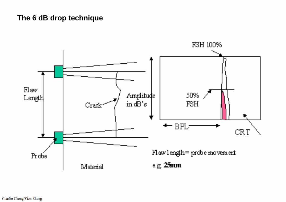
The 6 dB drop technique
The 6 dB drop technique
MaterialProbe
CrackReflected wave
50%FSH
6dB Drop Technique
http://www.twi-global.com/technical-knowledge/job-knowledge/ultrasonic-examination-part-2-128/

Other through-thickness sizing techniques are described in 9.9.7.1 through 9.9.7.4.
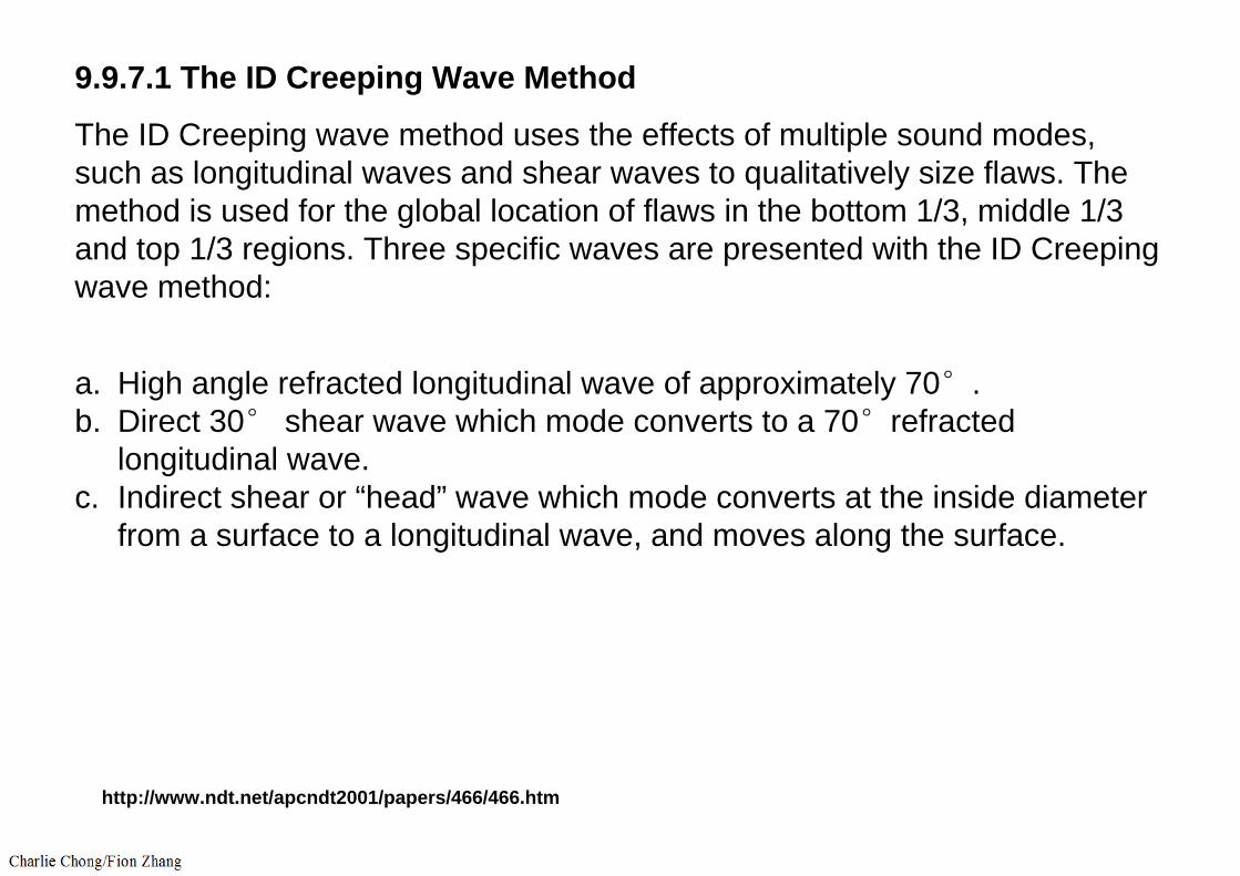
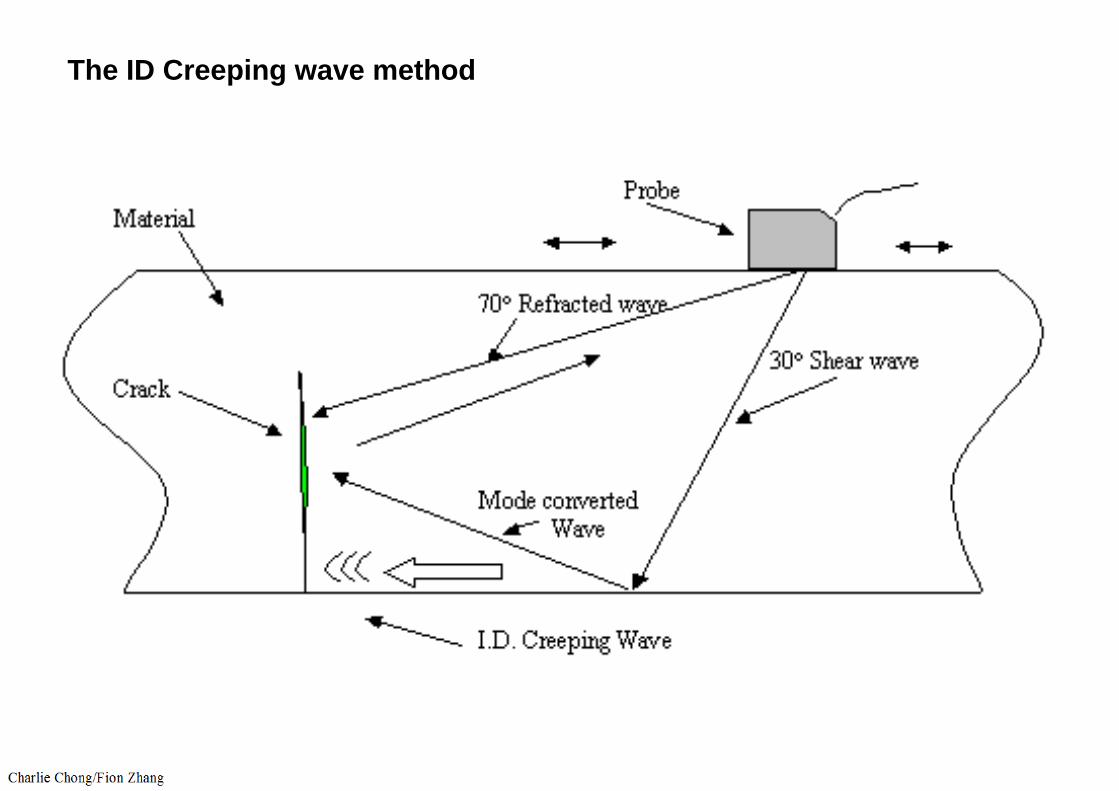
9.9.7.1 The ID Creeping Wave Method
The ID Creeping wave method uses the effects of multiple sound modes, such as longitudinal waves and shear waves to qualitatively size flaws. The method is used for the global location of flaws in the bottom 1/3, middle 1/3 and top 1/3 regions. Three specific waves are presented with the ID Creeping wave method:
a. High angle refracted longitudinal wave of approximately 70°.b. Direct 30° shear wave which mode converts to a 70°refracted
longitudinal wave.c. Indirect shear or “head” wave which mode converts at the inside diameter
from a surface to a longitudinal wave, and moves along the surface.
http://www.ndt.net/apcndt2001/papers/466/466.htm
The ID Creeping wave method

9.9.7.2 The Tip Diffraction Method
Tip diffraction methods are very effective for sizing flaws which are open to the inside or outside diameter surface and are shallow to mid-wall. For ID connected flaws, the half “V” path or one and one half “V” path technique is used. For OD connected flaws, two techniques are available; the time-of flighttip diffraction technique and the time measurement technique of the tip diffracted signal and the base signal.
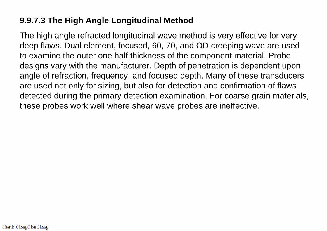
9.9.7.3 The High Angle Longitudinal Method
The high angle refracted longitudinal wave method is very effective for very deep flaws. Dual element, focused, 60, 70, and OD creeping wave are used to examine the outer one half thickness of the component material. Probe designs vary with the manufacturer. Depth of penetration is dependent uponangle of refraction, frequency, and focused depth. Many of these transducers are used not only for sizing, but also for detection and confirmation of flaws detected during the primary detection examination. For coarse grain materials, these probes work well where shear wave probes are ineffective.

9.9.7.4 The Bimodal Method
The bimodal method is a dual element tandem probe with the transducers crystals located one in front of the other. The probe also generates an ID creeping wave. The wave physics are essentially the same. The pseudo-focusing effect of the dual element crystals is very effective for ID connected flaws in the mid-wall region, 30 to 60% through wall depth. A low angle shear wave (indirect) mode converts at the ID to produce an ID creeping wave, which detects the base of the flaw. A further low angle shear wave mode converts at the ID to a longitudinal wave, which reflects a longitudinal wave from the flaw face. A high angle refracted longitudinal wave detects the upper extremity of the flaw (70°). The bimodal method can be used to confirm the depth of shallow to deep ID connected flaws. However, very shallow flaws of less than 10 to 20 percent tend to be slightly oversized, and very deep flaws tend to be slightly undersized. Significant training and experience is required to effectively utilize some of the more advanced UT detection and sizing techniques.
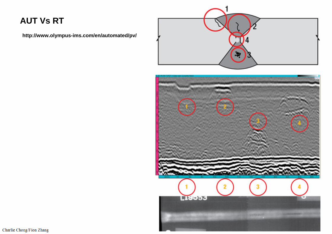
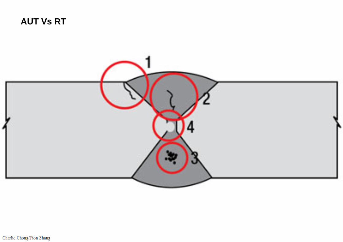
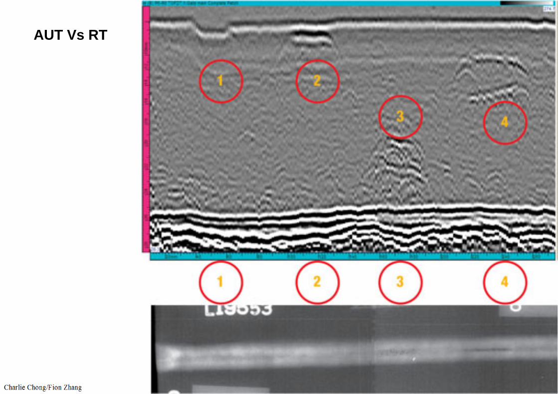
AUT Vs RThttp://www.olympus-ims.com/en/automated/pv/

AUT Vs RT
http://www.olympus-ims.com/en/automated/pv/
AUT Vs RT
AUT Vs RT

TOFD

TOFD
http://www.mhps.com/en/technology/business/power/service/inspection/tofd.html
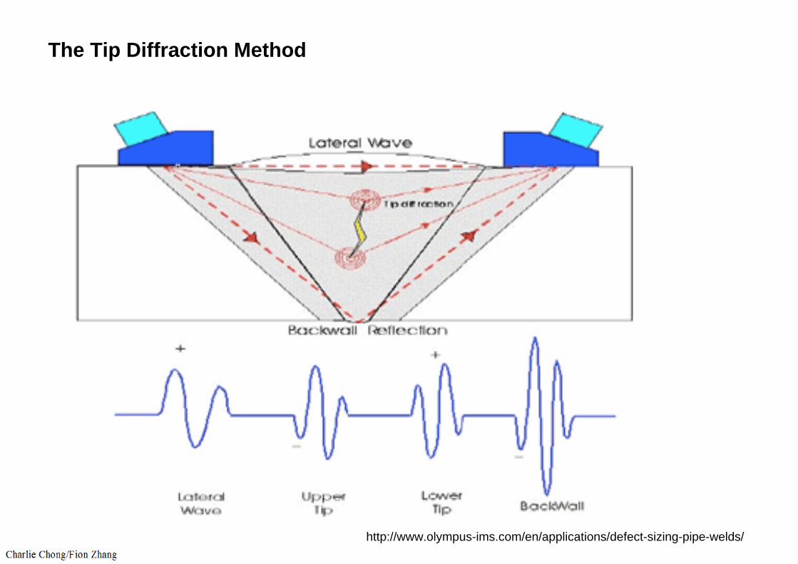
The Tip Diffraction Method
http://www.olympus-ims.com/en/applications/defect-sizing-pipe-welds/
Related Documents