Solutions for the Programming Industry www.rnsusa.com Understanding ISP Wiring With the high bit rates of today’s In-System Programming protocols, careful wiring between the programmer and the programming/testing fixture must be considered. Fewer Wires, Higher Speeds In-System Programming (ISP) is becoming the programming solution preferred by small and big OEM/EMS alike. Since each silicon manufacturer implements its own programming protocol(s), every device family has its own particular programming interface. Nonetheless, the lines needed to program a typical device have decreased during the years. Modern devices only need very few lines to be programmed; in some cases, just one line is needed (Fig. 1). At the same time, the devices’ non-volatile memory is rapidly increasing (Fig. 2). To keep programming times low, the ISP lines must therefore be capable of sustaining higher communication bit rates. Higher bit rates mean that the wiring of the ISP lines inside the programming/testing fixture has to be carefully thought. Fixture Wiring Usually, an Automatic Test Equipment (ATE) performs parametric and functional tests on the Unit Under Test (UUT) that is placed inside a custom, unit-specific test fixture. The text fixture routes several ATE control lines to the various test points on the UUT. The same fixture is used to in-system program the target device(s) (or DUP, Device Under Programming) in the UUT that needs to be programmed. In-system programming usually takes place after the component parametric test and before the functional test. Multi-PCB panels add to the complexity of the wiring inside the fixture; fixtures with hundreds of nails are not uncommon (Fig. 3). While the vast majority of connections required for board testing are low-speed transmission lines, the wiring of the lines dedicated to programming must take into account the high speed of modern ISP. ISP Wiring Issues One of the most important parameters to take into account for ISP wiring is connection length. Usually (but this is not always known to the test engineer), ISP signal integrity starts to degrade with connections longer than 40-50cm. For this reason the programmer should be placed as near as possible to the fixture, better yet inside the fixture. The 50cm limit should not be taken as an absolute maximum: it depends on the ISP protocol. Asynchronous protocols such as UART, for example, allow for longer connections; Freescale’s BDM protocol, due to the high bit rate and driving characteristics, requires shorter wiring. Number of ISP Lines Year 1990 2000 2010 1 4 8 Fig. 1 Device Memory (KB) Year 1990 2000 2010 10 100 1000 Fig. 2

Welcome message from author
This document is posted to help you gain knowledge. Please leave a comment to let me know what you think about it! Share it to your friends and learn new things together.
Transcript

Solutions for the Programming Industry
www.rnsusa.comSolutions for the Programming Industry
www.algocraft.com
Solutions for the Programming Industrywww.algocraft.com
Solutions for the Programming Industry
All information is subject to change without notice. Algocraft and WriteNow! are trademarks of Algocraft Srl.Rev. 1.0 - WP00010100EN
www.algocraft.com
Understanding ISP WiringWith the high bit rates of today’s In-System Programming protocols, careful
wiring between the programmer and the programming/testing �xture must be
considered.
Fewer Wires, Higher Speeds
In-System Programming (ISP) is becoming the programming solution preferred by small and big OEM/EMS alike. Since each silicon manufacturer implements its own programming protocol(s), every device family has its own particular programming interface. Nonetheless, the lines needed to program a typical device have decreased during the years. Modern devices only need very few lines to be programmed; in some cases, just one line is needed (Fig. 1).
At the same time, the devices’ non-volatile memory is rapidly increasing (Fig. 2). To keep programming times low, the ISP lines must therefore be capable of sustaining higher communication bit rates. Higher bit rates mean that the wiring of the ISP lines inside the programming/testing �xture has to be carefully thought.
Fixture Wiring
Usually, an Automatic Test Equipment (ATE) performs parametric and functional tests on the Unit Under Test (UUT) that is placed inside a custom, unit-speci�c test �xture. The text �xture routes several ATE control lines to the various test points on the UUT. The same �xture is used to in-system program the target device(s) (or DUP, Device Under Programming) in the UUT that needs to be programmed. In-system programming usually takes place after the component parametric test and before the functional test. Multi-PCB panels add to the complexity of the wiring inside the �xture; �xtures with hundreds of nails are not uncommon (Fig. 3).
While the vast majority of connections required for board testing are low-speed transmission lines, the wiring of the lines dedicated to programming must take into account the high speed of modern ISP.
ISP Wiring Issues
One of the most important parameters to take into account for ISP wiring is connection length. Usually (but this is not always known to the test engineer), ISP signal integrity starts to degrade with connections longer than 40-50cm. For this reason the programmer should be placed as near as possible to the �xture, better yet inside the �xture.
The 50cm limit should not be taken as an absolute maximum: it depends on the ISP protocol. Asynchronous protocols such as UART, for example, allow for longer connections; Freescale’s BDM protocol, due to the high bit rate and driving characteristics, requires shorter wiring.
An important role in an electric communication is played by the transmission line. Due to the high number of wires and to their connection typology (usually wire wrap, making solderless connections of wires to terminals), �xture wiring is typically done with single-core, isolated wires with AWG from 20 to 30.
Since almost all programmable devices (serial memories, microcontrollers, etc.) feature single-ended, CMOS lines, almost all In-System Programmers in the market feature single-ended, CMOS driving of ISP lines (Fig. 4).
This transmission line is easier to implement than a di�erential line, but it o�ers less immunity to common-mode noise. Programmer and DUP usually share the same ground potential and, with the simultaneous activity of several digital lines, electric noise will add both on the transmitter and receiver end—possibly corrupting the transmission. Fig. 5 shows a signal a�ected by common-mode noise.
Another source of noise can be the crosstalk phenom-enon. Crosstalk arises when a signal a�ects another nearby signal. Usually the coupling is capacitive, and to the nearest neighbor, but other forms of coupling and e�ects on signal further away are sometimes important.
Fig. 6 shows an example of crosstalk between two conductors inside a �xture. The CH1 signal is a�ected by the CH2 signal. The steeper the edges of the CH2 signal, and the higher the CH1 line impedance, the higher the crosstalk. ISP protocols such as I2C, ICC, etc., where the high logic state is obtained through open-drain driving, are more subject to the crosstalk phenomenon.
In order to reduce crosstalk, twisted pair cabling should be used, where a “shielding” conductor (only one end of which is connected to ground, usually on the programmer side) is twisted together with the main conductor (alternatively, a coaxial cable can be used). Fig. 7 shows the bene�ts of such a cabling. Fig. 8 shows how cable twisting should be implemented.
High-Speed Signals
Crosstalk e�ects are empathized by modern In-System Programmers since, in order to reach the higher bit rates of today’s ISP protocols, they employ high-speed single ended line driving. To help avoid crosstalk, the �xture should have a ground plane on the plate hosting the nails (Fig. 9).
Additionally, ground connections should be redundant; all the ground pins of the programmer should be individually connected to ground nails on the �xture, and these should be connected to each other, as shown in Fig. 10.
Impedance Matching
Impedance matching is another factor that improves signal transmission. A transmission line is said to be “matched” when its characteristic impedance (Zo) is equal to that of the transmitter (ZoTX) and to that of the receiver (ZoRX). When the transmission line is matched, signal re�ection and interferences are null (Fig. 11).
Understanding ISP Wiring
Understanding ISP Wiring Understanding ISP Wiring
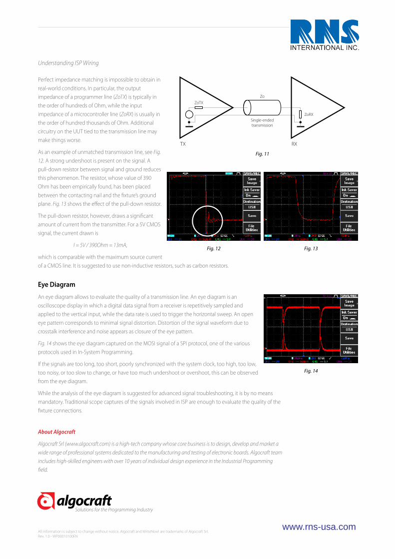
Perfect impedance matching is impossible to obtain in real-world conditions. In particular, the output impedance of a programmer line (ZoTX) is typically in the order of hundreds of Ohm, while the input impedance of a microcontroller line (ZoRX) is usually in the order of hundred thousands of Ohm. Additional circuitry on the UUT tied to the transmission line may make things worse.
As an example of unmatched transmission line, see Fig. 12. A strong undershoot is present on the signal. A pull-down resistor between signal and ground reduces this phenomenon. The resistor, whose value of 390 Ohm has been empirically found, has been placed between the contacting nail and the �xture’s ground plane. Fig. 13 shows the e�ect of the pull-down resistor.
The pull-down resistor, however, draws a signi�cant amount of current from the transmitter. For a 5V CMOS signal, the current drawn is
I = 5V / 390Ohm = 13mA,
which is comparable with the maximum source current of a CMOS line. It is suggested to use non-inductive resistors, such as carbon resistors.
Eye Diagram
An eye diagram allows to evaluate the quality of a transmission line. An eye diagram is an oscilloscope display in which a digital data signal from a receiver is repetitively sampled and applied to the vertical input, while the data rate is used to trigger the horizontal sweep. An open eye pattern corresponds to minimal signal distortion. Distortion of the signal waveform due to crosstalk interference and noise appears as closure of the eye pattern.
Fig. 14 shows the eye diagram captured on the MOSI signal of a SPI protocol, one of the various protocols used in In-System Programming.
If the signals are too long, too short, poorly synchronized with the system clock, too high, too low, too noisy, or too slow to change, or have too much undershoot or overshoot, this can be observed from the eye diagram.
While the analysis of the eye diagram is suggested for advanced signal troubleshooting, it is by no means mandatory. Traditional scope captures of the signals involved in ISP are enough to evaluate the quality of the �xture connections.
Number ofISP Lines
Year1990 2000 2010
1
4
8
Fig. 1
DeviceMemory
(KB)
Year1990 2000 2010
10
100
1000
Fig. 2
Fig. 3
In-SystemProgrammer
Single-endedtransmission
UUT
ISP VDD
ISP GND
UUT VDD
UUT GND
Fig. 4
Transmitteddigital signal
Neighboringsignal
Receiveddigital signal
Fig. 5
Fig. 6 Fig. 7
Fig. 9
Ground Plane
Ground wiresfrom programmer
Groundnails
Ground wiring connecting allground nails
Fig. 10
RX
Single-endedtransmission
TX
ZoTX
Zo
ZoRX
Fig. 11
Fig. 12 Fig. 13
Fig. 14
Fig. 8
In-SystemProgrammer UUT
ISP VDD
ISP GND
UUT VDD
UUT GNDTwisted pair cabling
About Algocraft
Algocraft Srl (www.algocraft.com) is a high-tech company whose core business is to design, develop and market a wide range of professional systems dedicated to the manufacturing and testing of electronic boards. Algocraft team includes high-skilled engineers with over 10 years of individual design experience in the Industrial Programming �eld.

Solutions for the Programming Industrywww.algocraft.com
Solutions for the Programming Industrywww.rnsusa.com
Solutions for the Programming Industrywww.algocraft.com
Solutions for the Programming Industry
All information is subject to change without notice. Algocraft and WriteNow! are trademarks of Algocraft Srl.Rev. 1.0 - WP00010100EN
www.algocraft.com
Understanding ISP WiringWith the high bit rates of today’s In-System Programming protocols, careful
wiring between the programmer and the programming/testing �xture must be
considered.
Fewer Wires, Higher Speeds
In-System Programming (ISP) is becoming the programming solution preferred by small and big OEM/EMS alike. Since each silicon manufacturer implements its own programming protocol(s), every device family has its own particular programming interface. Nonetheless, the lines needed to program a typical device have decreased during the years. Modern devices only need very few lines to be programmed; in some cases, just one line is needed (Fig. 1).
At the same time, the devices’ non-volatile memory is rapidly increasing (Fig. 2). To keep programming times low, the ISP lines must therefore be capable of sustaining higher communication bit rates. Higher bit rates mean that the wiring of the ISP lines inside the programming/testing �xture has to be carefully thought.
Fixture Wiring
Usually, an Automatic Test Equipment (ATE) performs parametric and functional tests on the Unit Under Test (UUT) that is placed inside a custom, unit-speci�c test �xture. The text �xture routes several ATE control lines to the various test points on the UUT. The same �xture is used to in-system program the target device(s) (or DUP, Device Under Programming) in the UUT that needs to be programmed. In-system programming usually takes place after the component parametric test and before the functional test. Multi-PCB panels add to the complexity of the wiring inside the �xture; �xtures with hundreds of nails are not uncommon (Fig. 3).
While the vast majority of connections required for board testing are low-speed transmission lines, the wiring of the lines dedicated to programming must take into account the high speed of modern ISP.
ISP Wiring Issues
One of the most important parameters to take into account for ISP wiring is connection length. Usually (but this is not always known to the test engineer), ISP signal integrity starts to degrade with connections longer than 40-50cm. For this reason the programmer should be placed as near as possible to the �xture, better yet inside the �xture.
The 50cm limit should not be taken as an absolute maximum: it depends on the ISP protocol. Asynchronous protocols such as UART, for example, allow for longer connections; Freescale’s BDM protocol, due to the high bit rate and driving characteristics, requires shorter wiring.
An important role in an electric communication is played by the transmission line. Due to the high number of wires and to their connection typology (usually wire wrap, making solderless connections of wires to terminals), �xture wiring is typically done with single-core, isolated wires with AWG from 20 to 30.
Since almost all programmable devices (serial memories, microcontrollers, etc.) feature single-ended, CMOS lines, almost all In-System Programmers in the market feature single-ended, CMOS driving of ISP lines (Fig. 4).
This transmission line is easier to implement than a di�erential line, but it o�ers less immunity to common-mode noise. Programmer and DUP usually share the same ground potential and, with the simultaneous activity of several digital lines, electric noise will add both on the transmitter and receiver end—possibly corrupting the transmission. Fig. 5 shows a signal a�ected by common-mode noise.
Another source of noise can be the crosstalk phenom-enon. Crosstalk arises when a signal a�ects another nearby signal. Usually the coupling is capacitive, and to the nearest neighbor, but other forms of coupling and e�ects on signal further away are sometimes important.
Fig. 6 shows an example of crosstalk between two conductors inside a �xture. The CH1 signal is a�ected by the CH2 signal. The steeper the edges of the CH2 signal, and the higher the CH1 line impedance, the higher the crosstalk. ISP protocols such as I2C, ICC, etc., where the high logic state is obtained through open-drain driving, are more subject to the crosstalk phenomenon.
In order to reduce crosstalk, twisted pair cabling should be used, where a “shielding” conductor (only one end of which is connected to ground, usually on the programmer side) is twisted together with the main conductor (alternatively, a coaxial cable can be used). Fig. 7 shows the bene�ts of such a cabling. Fig. 8 shows how cable twisting should be implemented.
High-Speed Signals
Crosstalk e�ects are empathized by modern In-System Programmers since, in order to reach the higher bit rates of today’s ISP protocols, they employ high-speed single ended line driving. To help avoid crosstalk, the �xture should have a ground plane on the plate hosting the nails (Fig. 9).
Additionally, ground connections should be redundant; all the ground pins of the programmer should be individually connected to ground nails on the �xture, and these should be connected to each other, as shown in Fig. 10.
Impedance Matching
Impedance matching is another factor that improves signal transmission. A transmission line is said to be “matched” when its characteristic impedance (Zo) is equal to that of the transmitter (ZoTX) and to that of the receiver (ZoRX). When the transmission line is matched, signal re�ection and interferences are null (Fig. 11).
Understanding ISP Wiring
Understanding ISP Wiring Understanding ISP Wiring
Perfect impedance matching is impossible to obtain in real-world conditions. In particular, the output impedance of a programmer line (ZoTX) is typically in the order of hundreds of Ohm, while the input impedance of a microcontroller line (ZoRX) is usually in the order of hundred thousands of Ohm. Additional circuitry on the UUT tied to the transmission line may make things worse.
As an example of unmatched transmission line, see Fig. 12. A strong undershoot is present on the signal. A pull-down resistor between signal and ground reduces this phenomenon. The resistor, whose value of 390 Ohm has been empirically found, has been placed between the contacting nail and the �xture’s ground plane. Fig. 13 shows the e�ect of the pull-down resistor.
The pull-down resistor, however, draws a signi�cant amount of current from the transmitter. For a 5V CMOS signal, the current drawn is
I = 5V / 390Ohm = 13mA,
which is comparable with the maximum source current of a CMOS line. It is suggested to use non-inductive resistors, such as carbon resistors.
Eye Diagram
An eye diagram allows to evaluate the quality of a transmission line. An eye diagram is an oscilloscope display in which a digital data signal from a receiver is repetitively sampled and applied to the vertical input, while the data rate is used to trigger the horizontal sweep. An open eye pattern corresponds to minimal signal distortion. Distortion of the signal waveform due to crosstalk interference and noise appears as closure of the eye pattern.
Fig. 14 shows the eye diagram captured on the MOSI signal of a SPI protocol, one of the various protocols used in In-System Programming.
If the signals are too long, too short, poorly synchronized with the system clock, too high, too low, too noisy, or too slow to change, or have too much undershoot or overshoot, this can be observed from the eye diagram.
While the analysis of the eye diagram is suggested for advanced signal troubleshooting, it is by no means mandatory. Traditional scope captures of the signals involved in ISP are enough to evaluate the quality of the �xture connections.
Number ofISP Lines
Year1990 2000 2010
1
4
8
Fig. 1
DeviceMemory
(KB)
Year1990 2000 2010
10
100
1000
Fig. 2
Fig. 3
In-SystemProgrammer
Single-endedtransmission
UUT
ISP VDD
ISP GND
UUT VDD
UUT GND
Fig. 4
Transmitteddigital signal
Neighboringsignal
Receiveddigital signal
Fig. 5
Fig. 6 Fig. 7
Fig. 9
Ground Plane
Ground wiresfrom programmer
Groundnails
Ground wiring connecting allground nails
Fig. 10
RX
Single-endedtransmission
TX
ZoTX
Zo
ZoRX
Fig. 11
Fig. 12 Fig. 13
Fig. 14
Fig. 8
In-SystemProgrammer UUT
ISP VDD
ISP GND
UUT VDD
UUT GNDTwisted pair cabling
About Algocraft
Algocraft Srl (www.algocraft.com) is a high-tech company whose core business is to design, develop and market a wide range of professional systems dedicated to the manufacturing and testing of electronic boards. Algocraft team includes high-skilled engineers with over 10 years of individual design experience in the Industrial Programming �eld.

Solutions for the Programming Industrywww.algocraft.com
Solutions for the Programming Industrywww.algocraft.com
Solutions for the Programming Industry www.rnsusa.comSolutions for the Programming Industry
All information is subject to change without notice. Algocraft and WriteNow! are trademarks of Algocraft Srl.Rev. 1.0 - WP00010100EN
www.algocraft.com
Understanding ISP WiringWith the high bit rates of today’s In-System Programming protocols, careful
wiring between the programmer and the programming/testing �xture must be
considered.
Fewer Wires, Higher Speeds
In-System Programming (ISP) is becoming the programming solution preferred by small and big OEM/EMS alike. Since each silicon manufacturer implements its own programming protocol(s), every device family has its own particular programming interface. Nonetheless, the lines needed to program a typical device have decreased during the years. Modern devices only need very few lines to be programmed; in some cases, just one line is needed (Fig. 1).
At the same time, the devices’ non-volatile memory is rapidly increasing (Fig. 2). To keep programming times low, the ISP lines must therefore be capable of sustaining higher communication bit rates. Higher bit rates mean that the wiring of the ISP lines inside the programming/testing �xture has to be carefully thought.
Fixture Wiring
Usually, an Automatic Test Equipment (ATE) performs parametric and functional tests on the Unit Under Test (UUT) that is placed inside a custom, unit-speci�c test �xture. The text �xture routes several ATE control lines to the various test points on the UUT. The same �xture is used to in-system program the target device(s) (or DUP, Device Under Programming) in the UUT that needs to be programmed. In-system programming usually takes place after the component parametric test and before the functional test. Multi-PCB panels add to the complexity of the wiring inside the �xture; �xtures with hundreds of nails are not uncommon (Fig. 3).
While the vast majority of connections required for board testing are low-speed transmission lines, the wiring of the lines dedicated to programming must take into account the high speed of modern ISP.
ISP Wiring Issues
One of the most important parameters to take into account for ISP wiring is connection length. Usually (but this is not always known to the test engineer), ISP signal integrity starts to degrade with connections longer than 40-50cm. For this reason the programmer should be placed as near as possible to the �xture, better yet inside the �xture.
The 50cm limit should not be taken as an absolute maximum: it depends on the ISP protocol. Asynchronous protocols such as UART, for example, allow for longer connections; Freescale’s BDM protocol, due to the high bit rate and driving characteristics, requires shorter wiring.
An important role in an electric communication is played by the transmission line. Due to the high number of wires and to their connection typology (usually wire wrap, making solderless connections of wires to terminals), �xture wiring is typically done with single-core, isolated wires with AWG from 20 to 30.
Since almost all programmable devices (serial memories, microcontrollers, etc.) feature single-ended, CMOS lines, almost all In-System Programmers in the market feature single-ended, CMOS driving of ISP lines (Fig. 4).
This transmission line is easier to implement than a di�erential line, but it o�ers less immunity to common-mode noise. Programmer and DUP usually share the same ground potential and, with the simultaneous activity of several digital lines, electric noise will add both on the transmitter and receiver end—possibly corrupting the transmission. Fig. 5 shows a signal a�ected by common-mode noise.
Another source of noise can be the crosstalk phenom-enon. Crosstalk arises when a signal a�ects another nearby signal. Usually the coupling is capacitive, and to the nearest neighbor, but other forms of coupling and e�ects on signal further away are sometimes important.
Fig. 6 shows an example of crosstalk between two conductors inside a �xture. The CH1 signal is a�ected by the CH2 signal. The steeper the edges of the CH2 signal, and the higher the CH1 line impedance, the higher the crosstalk. ISP protocols such as I2C, ICC, etc., where the high logic state is obtained through open-drain driving, are more subject to the crosstalk phenomenon.
In order to reduce crosstalk, twisted pair cabling should be used, where a “shielding” conductor (only one end of which is connected to ground, usually on the programmer side) is twisted together with the main conductor (alternatively, a coaxial cable can be used). Fig. 7 shows the bene�ts of such a cabling. Fig. 8 shows how cable twisting should be implemented.
High-Speed Signals
Crosstalk e�ects are empathized by modern In-System Programmers since, in order to reach the higher bit rates of today’s ISP protocols, they employ high-speed single ended line driving. To help avoid crosstalk, the �xture should have a ground plane on the plate hosting the nails (Fig. 9).
Additionally, ground connections should be redundant; all the ground pins of the programmer should be individually connected to ground nails on the �xture, and these should be connected to each other, as shown in Fig. 10.
Impedance Matching
Impedance matching is another factor that improves signal transmission. A transmission line is said to be “matched” when its characteristic impedance (Zo) is equal to that of the transmitter (ZoTX) and to that of the receiver (ZoRX). When the transmission line is matched, signal re�ection and interferences are null (Fig. 11).
Understanding ISP Wiring
Understanding ISP Wiring Understanding ISP Wiring
Perfect impedance matching is impossible to obtain in real-world conditions. In particular, the output impedance of a programmer line (ZoTX) is typically in the order of hundreds of Ohm, while the input impedance of a microcontroller line (ZoRX) is usually in the order of hundred thousands of Ohm. Additional circuitry on the UUT tied to the transmission line may make things worse.
As an example of unmatched transmission line, see Fig. 12. A strong undershoot is present on the signal. A pull-down resistor between signal and ground reduces this phenomenon. The resistor, whose value of 390 Ohm has been empirically found, has been placed between the contacting nail and the �xture’s ground plane. Fig. 13 shows the e�ect of the pull-down resistor.
The pull-down resistor, however, draws a signi�cant amount of current from the transmitter. For a 5V CMOS signal, the current drawn is
I = 5V / 390Ohm = 13mA,
which is comparable with the maximum source current of a CMOS line. It is suggested to use non-inductive resistors, such as carbon resistors.
Eye Diagram
An eye diagram allows to evaluate the quality of a transmission line. An eye diagram is an oscilloscope display in which a digital data signal from a receiver is repetitively sampled and applied to the vertical input, while the data rate is used to trigger the horizontal sweep. An open eye pattern corresponds to minimal signal distortion. Distortion of the signal waveform due to crosstalk interference and noise appears as closure of the eye pattern.
Fig. 14 shows the eye diagram captured on the MOSI signal of a SPI protocol, one of the various protocols used in In-System Programming.
If the signals are too long, too short, poorly synchronized with the system clock, too high, too low, too noisy, or too slow to change, or have too much undershoot or overshoot, this can be observed from the eye diagram.
While the analysis of the eye diagram is suggested for advanced signal troubleshooting, it is by no means mandatory. Traditional scope captures of the signals involved in ISP are enough to evaluate the quality of the �xture connections.
Number ofISP Lines
Year1990 2000 2010
1
4
8
Fig. 1
DeviceMemory
(KB)
Year1990 2000 2010
10
100
1000
Fig. 2
Fig. 3
In-SystemProgrammer
Single-endedtransmission
UUT
ISP VDD
ISP GND
UUT VDD
UUT GND
Fig. 4
Transmitteddigital signal
Neighboringsignal
Receiveddigital signal
Fig. 5
Fig. 6 Fig. 7
Fig. 9
Ground Plane
Ground wiresfrom programmer
Groundnails
Ground wiring connecting allground nails
Fig. 10
RX
Single-endedtransmission
TX
ZoTX
Zo
ZoRX
Fig. 11
Fig. 12 Fig. 13
Fig. 14
Fig. 8
In-SystemProgrammer UUT
ISP VDD
ISP GND
UUT VDD
UUT GNDTwisted pair cabling
About Algocraft
Algocraft Srl (www.algocraft.com) is a high-tech company whose core business is to design, develop and market a wide range of professional systems dedicated to the manufacturing and testing of electronic boards. Algocraft team includes high-skilled engineers with over 10 years of individual design experience in the Industrial Programming �eld.
Solutions for the Programming Industrywww.algocraft.com
Solutions for the Programming Industrywww.algocraft.com
Solutions for the Programming Industrywww.algocraft.com
Solutions for the Programming Industry
All information is subject to change without notice. Algocraft and WriteNow! are trademarks of Algocraft Srl.Rev. 1.0 - WP00010100EN
www.rnsusa.com
Understanding ISP WiringWith the high bit rates of today’s In-System Programming protocols, careful
wiring between the programmer and the programming/testing �xture must be
considered.
Fewer Wires, Higher Speeds
In-System Programming (ISP) is becoming the programming solution preferred by small and big OEM/EMS alike. Since each silicon manufacturer implements its own programming protocol(s), every device family has its own particular programming interface. Nonetheless, the lines needed to program a typical device have decreased during the years. Modern devices only need very few lines to be programmed; in some cases, just one line is needed (Fig. 1).
At the same time, the devices’ non-volatile memory is rapidly increasing (Fig. 2). To keep programming times low, the ISP lines must therefore be capable of sustaining higher communication bit rates. Higher bit rates mean that the wiring of the ISP lines inside the programming/testing �xture has to be carefully thought.
Fixture Wiring
Usually, an Automatic Test Equipment (ATE) performs parametric and functional tests on the Unit Under Test (UUT) that is placed inside a custom, unit-speci�c test �xture. The text �xture routes several ATE control lines to the various test points on the UUT. The same �xture is used to in-system program the target device(s) (or DUP, Device Under Programming) in the UUT that needs to be programmed. In-system programming usually takes place after the component parametric test and before the functional test. Multi-PCB panels add to the complexity of the wiring inside the �xture; �xtures with hundreds of nails are not uncommon (Fig. 3).
While the vast majority of connections required for board testing are low-speed transmission lines, the wiring of the lines dedicated to programming must take into account the high speed of modern ISP.
ISP Wiring Issues
One of the most important parameters to take into account for ISP wiring is connection length. Usually (but this is not always known to the test engineer), ISP signal integrity starts to degrade with connections longer than 40-50cm. For this reason the programmer should be placed as near as possible to the �xture, better yet inside the �xture.
The 50cm limit should not be taken as an absolute maximum: it depends on the ISP protocol. Asynchronous protocols such as UART, for example, allow for longer connections; Freescale’s BDM protocol, due to the high bit rate and driving characteristics, requires shorter wiring.
An important role in an electric communication is played by the transmission line. Due to the high number of wires and to their connection typology (usually wire wrap, making solderless connections of wires to terminals), �xture wiring is typically done with single-core, isolated wires with AWG from 20 to 30.
Since almost all programmable devices (serial memories, microcontrollers, etc.) feature single-ended, CMOS lines, almost all In-System Programmers in the market feature single-ended, CMOS driving of ISP lines (Fig. 4).
This transmission line is easier to implement than a di�erential line, but it o�ers less immunity to common-mode noise. Programmer and DUP usually share the same ground potential and, with the simultaneous activity of several digital lines, electric noise will add both on the transmitter and receiver end—possibly corrupting the transmission. Fig. 5 shows a signal a�ected by common-mode noise.
Another source of noise can be the crosstalk phenom-enon. Crosstalk arises when a signal a�ects another nearby signal. Usually the coupling is capacitive, and to the nearest neighbor, but other forms of coupling and e�ects on signal further away are sometimes important.
Fig. 6 shows an example of crosstalk between two conductors inside a �xture. The CH1 signal is a�ected by the CH2 signal. The steeper the edges of the CH2 signal, and the higher the CH1 line impedance, the higher the crosstalk. ISP protocols such as I2C, ICC, etc., where the high logic state is obtained through open-drain driving, are more subject to the crosstalk phenomenon.
In order to reduce crosstalk, twisted pair cabling should be used, where a “shielding” conductor (only one end of which is connected to ground, usually on the programmer side) is twisted together with the main conductor (alternatively, a coaxial cable can be used). Fig. 7 shows the bene�ts of such a cabling. Fig. 8 shows how cable twisting should be implemented.
High-Speed Signals
Crosstalk e�ects are empathized by modern In-System Programmers since, in order to reach the higher bit rates of today’s ISP protocols, they employ high-speed single ended line driving. To help avoid crosstalk, the �xture should have a ground plane on the plate hosting the nails (Fig. 9).
Additionally, ground connections should be redundant; all the ground pins of the programmer should be individually connected to ground nails on the �xture, and these should be connected to each other, as shown in Fig. 10.
Impedance Matching
Impedance matching is another factor that improves signal transmission. A transmission line is said to be “matched” when its characteristic impedance (Zo) is equal to that of the transmitter (ZoTX) and to that of the receiver (ZoRX). When the transmission line is matched, signal re�ection and interferences are null (Fig. 11).
Understanding ISP Wiring
Understanding ISP Wiring
Understanding ISP Wiring
Perfect impedance matching is impossible to obtain in real-world conditions. In particular, the output impedance of a programmer line (ZoTX) is typically in the order of hundreds of Ohm, while the input impedance of a microcontroller line (ZoRX) is usually in the order of hundred thousands of Ohm. Additional circuitry on the UUT tied to the transmission line may make things worse.
As an example of unmatched transmission line, see Fig. 12. A strong undershoot is present on the signal. A pull-down resistor between signal and ground reduces this phenomenon. The resistor, whose value of 390 Ohm has been empirically found, has been placed between the contacting nail and the �xture’s ground plane. Fig. 13 shows the e�ect of the pull-down resistor.
The pull-down resistor, however, draws a signi�cant amount of current from the transmitter. For a 5V CMOS signal, the current drawn is
I = 5V / 390Ohm = 13mA,
which is comparable with the maximum source current of a CMOS line. It is suggested to use non-inductive resistors, such as carbon resistors.
Eye Diagram
An eye diagram allows to evaluate the quality of a transmission line. An eye diagram is an oscilloscope display in which a digital data signal from a receiver is repetitively sampled and applied to the vertical input, while the data rate is used to trigger the horizontal sweep. An open eye pattern corresponds to minimal signal distortion. Distortion of the signal waveform due to crosstalk interference and noise appears as closure of the eye pattern.
Fig. 14 shows the eye diagram captured on the MOSI signal of a SPI protocol, one of the various protocols used in In-System Programming.
If the signals are too long, too short, poorly synchronized with the system clock, too high, too low, too noisy, or too slow to change, or have too much undershoot or overshoot, this can be observed from the eye diagram.
While the analysis of the eye diagram is suggested for advanced signal troubleshooting, it is by no means mandatory. Traditional scope captures of the signals involved in ISP are enough to evaluate the quality of the �xture connections.
Number ofISP Lines
Year1990 2000 2010
1
4
8
Fig. 1
DeviceMemory
(KB)
Year1990 2000 2010
10
100
1000
Fig. 2
Fig. 3
In-SystemProgrammer
Single-endedtransmission
UUT
ISP VDD
ISP GND
UUT VDD
UUT GND
Fig. 4
Transmitteddigital signal
Neighboringsignal
Receiveddigital signal
Fig. 5
Fig. 6 Fig. 7
Fig. 9
Ground Plane
Ground wiresfrom programmer
Groundnails
Ground wiring connecting allground nails
Fig. 10
RX
Single-endedtransmission
TX
ZoTX
Zo
ZoRX
Fig. 11
Fig. 12 Fig. 13
Fig. 14
Fig. 8
In-SystemProgrammer UUT
ISP VDD
ISP GND
UUT VDD
UUT GNDTwisted pair cabling
About Algocraft
Algocraft Srl (www.algocraft.com) is a high-tech company whose core business is to design, develop and market a wide range of professional systems dedicated to the manufacturing and testing of electronic boards. Algocraft team includes high-skilled engineers with over 10 years of individual design experience in the Industrial Programming �eld.
Related Documents