UNDERSTANDING SOLAR CONCENTRATORS By George M. Kaplan Technical Reviewers Dr. Thomas E. Bowman Dr. Maurice Raiford Jesse Ribot Illustrated By Rick Jali Published By VITA 1600 Wilson Boulevard, Suite 500 Arlington, Virginia 22209 USA Tel: 703/276-1800 * Fax: 703/243-1865 Internet: [email protected] Understanding Solar Concentrators ISBN: 0-86619-239-5 [C] 1985, Volunteers in Technical Assistance PREFACE This paper is one of a series published by Volunteers in Technical Assistance to provide an introduction to specific state-of-the-art technologies of interest to people in developing countries. The papers are intended to be used as guidelines to help people choose technologies that are suitable to their situations. They are not intended to provide construction or implementation details. People are urged to contact VITA or a similar organization for further information and technical assistance if they find that a particular technology seems to meet their needs. The papers in the series were written, reviewed, and illustrated almost entirely by VITA Volunteer technical

Welcome message from author
This document is posted to help you gain knowledge. Please leave a comment to let me know what you think about it! Share it to your friends and learn new things together.
Transcript

8/2/2019 Understanding Concentrated Solar Power
http://slidepdf.com/reader/full/understanding-concentrated-solar-power 1/49
UNDERSTANDING SOLAR CONCENTRATORS
By
George M. Kaplan
Technical Reviewers
Dr. Thomas E. Bowman
Dr. Maurice Raiford
Jesse Ribot
Illustrated By
Rick Jali
Published By
VITA
1600 Wilson Boulevard, Suite 500
Arlington, Virginia 22209 USA
Tel: 703/276-1800 * Fax: 703/243-1865
Internet: [email protected]
Understanding Solar Concentrators
ISBN: 0-86619-239-5
[C] 1985, Volunteers in Technical Assistance
PREFACE
This paper is one of a series published by Volunteers in
Technical Assistance to provide an introduction to specific
state-of-the-art technologies of interest to people in
developing countries.
The papers are intended to be used as guidelines to help
people choose technologies that are suitable to their
situations. They are not intended to provide constructionor implementation details. People are urged to contact
VITA or a similar organization for further information and
technical assistance if they find that a particular
technology seems to meet their needs.
The papers in the series were written, reviewed, and
illustrated almost entirely by VITA Volunteer technical
8/2/2019 Understanding Concentrated Solar Power
http://slidepdf.com/reader/full/understanding-concentrated-solar-power 2/49
experts on a purely voluntary basis. Some 500 volunteers
were involved in the production of the first 100 titles
issued, contributing approximately 5,000 hours of their
time. VITA staff included Maria Giannuzzi as editor,
Suzanne Brooks handling typesetting and layout, and
Margaret Crouch as project manager.
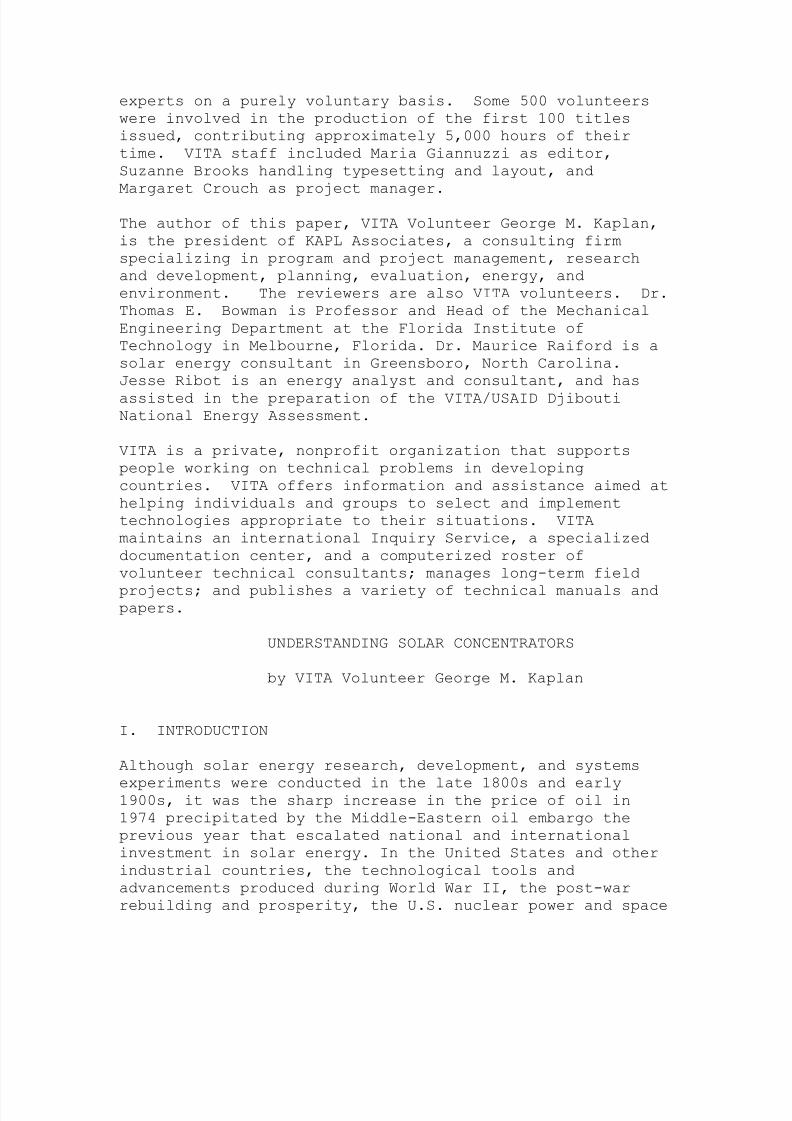
The author of this paper, VITA Volunteer George M. Kaplan,
is the president of KAPL Associates, a consulting firm
specializing in program and project management, research
and development, planning, evaluation, energy, and
environment. The reviewers are also VITA volunteers. Dr.
Thomas E. Bowman is Professor and Head of the Mechanical
Engineering Department at the Florida Institute of
Technology in Melbourne, Florida. Dr. Maurice Raiford is a
solar energy consultant in Greensboro, North Carolina.
Jesse Ribot is an energy analyst and consultant, and has
assisted in the preparation of the VITA/USAID DjiboutiNational Energy Assessment.
VITA is a private, nonprofit organization that supports
people working on technical problems in developing
countries. VITA offers information and assistance aimed at
helping individuals and groups to select and implement
technologies appropriate to their situations. VITA
maintains an international Inquiry Service, a specialized
documentation center, and a computerized roster of
volunteer technical consultants; manages long-term field
projects; and publishes a variety of technical manuals andpapers.
UNDERSTANDING SOLAR CONCENTRATORS
by VITA Volunteer George M. Kaplan
I. INTRODUCTION
Although solar energy research, development, and systems
experiments were conducted in the late 1800s and early1900s, it was the sharp increase in the price of oil in
1974 precipitated by the Middle-Eastern oil embargo the
previous year that escalated national and international
investment in solar energy. In the United States and other
industrial countries, the technological tools and
advancements produced during World War II, the post-war
rebuilding and prosperity, the U.S. nuclear power and space

8/2/2019 Understanding Concentrated Solar Power
http://slidepdf.com/reader/full/understanding-concentrated-solar-power 3/49
programs, and other technological achievements were applied
to solar energy research and development. The result was
that research, which had been limited to backyard tinkerers
and small specialized companies, was spread to
universities, national laboratories,and industry. The
federal solar budget rose from less than $1 million in
arly 1970s to over $1 billion in the early 1980s; the
budget is now about $200 million, with about $50 million
for solar thermal technology.
Solar thermal technology is concerned principally with the
utilization of solar energy by converting it to heat. In
the concentrating type of solar collector, solar energy is
collected and concentrated so that higher temperatures can
be obtained; the limit is the surface temperature of the
sun. However, construction materials impose a lower, more
practical limit for temperature capability. Similarly,
overall efficiency of energy collection, concentration, andretention, as it relates to energy cost,imposes a practical
limit on temperature capability.
If solar energy were very highly concentrated into a tiny
volume,the result would approach a miniature sun. If the
same energy were distributed along a thin line, the line
would be cooler than the miniature sun, but still hot. If
distributed on a large surface, the surface would be less
hot than the line. There are solar concentrators that
focus sunlight into a point or a line.
There are also non-focusing concentrators.Each type haspreferred temperature-dependent applications.
The amount of energy per unit area that can be collected
annually
by a concentrator depends on the positioning of the
concentrator
relative to the sun. Some types of collectors perform
adequately
(cost effectively) if left in a fixed position. These
collectors
generally have limited temperature capability, and providelittle
or no concentration of the incident sunlight. Most
concentrators
would collect so little energy in a fixed position that
they must
be provided with the capability to daily track the sun from
morning (east) to sunset (west) to be cost-effective.

8/2/2019 Understanding Concentrated Solar Power
http://slidepdf.com/reader/full/understanding-concentrated-solar-power 4/49
Some concentrators can only be cost effective by tracking
both the sun's daily path and the sun's annual inclination
(which causes the sun to appear to move in declination by
47 [degrees] over the year). Thus,concentrators may be
non-tracking, single-axis tracking (which tracks east to
west), or two-axis tracking (which tracks both east to west
and north to south). Two-axis tracking provides the
maximum solar energy collection but is not cost effective
for most applications or collector designs.
The U.S. national solar energy research program has led the
world both in investment and breadth of program. Because
the potential
U.S. market is large, the U.S. national program was aimed
at the
domestic market and was not intended specifically for
export.
Thus, the U.S. experience is primarily applicable to theU.S. and
may not be relevant to other countries without modification.
For U.S. applications, for example, mirror-type
concentrators are
more cost effective than lens-type concentrators for small,
intermediate,
and large systems for heat generation and use. Tracking
systems appear most effective for high-temperature
applications.
However, the effectiveness in the U.S. may be due tosophisticated technology, availability of skilled
maintenance
personnel and spare parts, an excellent supporting
infrastructure,
rather than an inherent advantage of mirrors or tracking
systems. In a less industrialized environment, lens
concentrators
may prove more appropriate.
Although the terms "collector" and "concentrator" are used
interchangeablyin this paper, the terms are distinctive. A collector
may not concentrate solar radiation, while concentrators are
considered collectors. No distinction will be made in this
paper
unless necessary.
HISTORY OF SOLAR CONCENTRATORS
8/2/2019 Understanding Concentrated Solar Power
http://slidepdf.com/reader/full/understanding-concentrated-solar-power 5/49
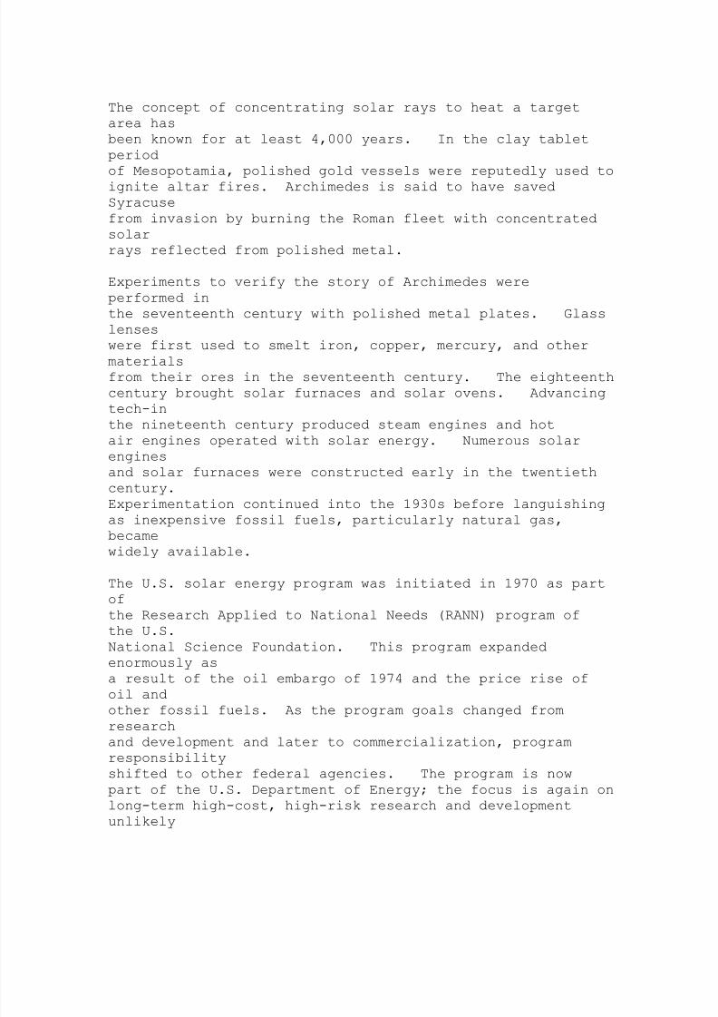
The concept of concentrating solar rays to heat a target
area has
been known for at least 4,000 years. In the clay tablet
period
of Mesopotamia, polished gold vessels were reputedly used to
ignite altar fires. Archimedes is said to have saved
Syracuse
from invasion by burning the Roman fleet with concentrated
solar
rays reflected from polished metal.
Experiments to verify the story of Archimedes were
performed in
the seventeenth century with polished metal plates. Glass
lenses
were first used to smelt iron, copper, mercury, and other
materialsfrom their ores in the seventeenth century. The eighteenth
century brought solar furnaces and solar ovens. Advancing
tech-in
the nineteenth century produced steam engines and hot
air engines operated with solar energy. Numerous solar
engines
and solar furnaces were constructed early in the twentieth
century.
Experimentation continued into the 1930s before languishing
as inexpensive fossil fuels, particularly natural gas,
becamewidely available.
The U.S. solar energy program was initiated in 1970 as part
of
the Research Applied to National Needs (RANN) program of
the U.S.
National Science Foundation. This program expanded
enormously as
a result of the oil embargo of 1974 and the price rise of
oil and
other fossil fuels. As the program goals changed fromresearch
and development and later to commercialization, program
responsibility
shifted to other federal agencies. The program is now
part of the U.S. Department of Energy; the focus is again on
long-term high-cost, high-risk research and development
unlikely

8/2/2019 Understanding Concentrated Solar Power
http://slidepdf.com/reader/full/understanding-concentrated-solar-power 6/49
8/2/2019 Understanding Concentrated Solar Power
http://slidepdf.com/reader/full/understanding-concentrated-solar-power 7/49
efficiency,
the design of the cell assembly, and the cell material will
determine if natural circulation or forced circulation
cooling is
necessary for efficient operation of the cell. Currently,
the
cost/unit area of a concentrator is less than the cost/unit
cell
area. As a result, concentrators are used to reduce cell
area.
Should the cell area become less expensive than the
concentrator
area, concentrators would not be utilized.
This paper deals principally with concentrators for thermal
applications
rather than for applications with photovoltaic cells.
Emphasis is placed on applications in less developedcountries.
II. OPERATING PRINCIPLES
SUNLIGHT
Before discussing concentrators, a few words about the sun
are in
order. Beyond the earth's atmosphere the intensity of
sunlight
is about 1,350 watts per square meter (429 British thermalunits
[Btu] per hour per square foot). Passage through the
atmosphere
depletes the intensity due to absorption by the various
gases and
vapors in the air and by scattering from these gases and
vapors
and from particles of dust and ice also in the air. Thus,
sunlight
reaching the earth is a mixture of direct (unscattered) and
diffuse (scattered) radiation. At sea level the intensityis
reduced to approximately 1,000 watts/square meter (295
Btu/hour/
square foot) on a bright clear day. The intensity is
further reduced
on overcast days.
8/2/2019 Understanding Concentrated Solar Power
http://slidepdf.com/reader/full/understanding-concentrated-solar-power 8/49
Most concentrators utilize direct radiation only. These
concentrators
work well on bright clear days, poorly on hazy days, and
not at all on drab gray days when the sunlight intensity is
reduced and the light consists principally of diffuse
radiation.
Another limiting factor is that the sun is not a point but
has a
diameter equivalent to about one-half degree of arc.
Concentrator
design must consider this arc.
GENERIC TYPES AND USE
Although the discussion that follows deals with
concentrators as
entities, concentrators are only a portion of an energy
collectionsystem. To be useful the concentrated rays must be directed
to a target called a receiver, which converts the rays into
another form of energy, heat. The concentrator and
receiver must
be matched for optimum performance. Frequently, the
receiver is
expected to impart heat to a fluid in order that the heat be
utilized or dissipated. When the main purpose of the
concentrator
is to obtain heat effectively, then the combination of
concentratorand receiver must be carefully designed to reduce stray
loss of energy from either the concentrator or receiver.
There are many ways to characterize concentrators. These
include:
o Means of concentration--reflection or refraction
o Point, line, or non-focusing
o Fixed or tracking concentrator
o Fixed or tracking receiver
Means of Concentration
Concentration of light is achieved with mirrors
(reflection) or
with transparent lens (refraction). Cameras and small
telescopes
use lenses; large telescopes use mirrors. A mirror

8/2/2019 Understanding Concentrated Solar Power
http://slidepdf.com/reader/full/understanding-concentrated-solar-power 9/49
reflects
incoming light so that the angle of the reflected ray is
equal to
the angle of the incident ray (Figure 1). This relation
also
25p05a.gif (486x486)
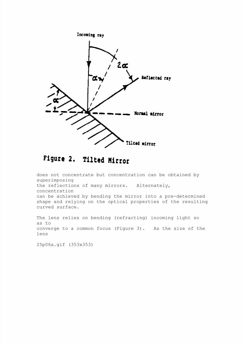
holds when the mirror is tilted (Figure 2). A single flat
mirror
25p05b.gif (486x486)
8/2/2019 Understanding Concentrated Solar Power
http://slidepdf.com/reader/full/understanding-concentrated-solar-power 10/49
does not concentrate but concentration can be obtained by
superimposingthe reflections of many mirrors. Alternately,
concentration
can be achieved by bending the mirror into a pre-determined
shape and relying on the optical properties of the resulting
curved surface.
The lens relies on bending (refracting) incoming light so
as to
converge to a common focus (Figure 3). As the size of the
lens
25p06a.gif (353x353)

8/2/2019 Understanding Concentrated Solar Power
http://slidepdf.com/reader/full/understanding-concentrated-solar-power 11/49
increases, lens thickness also increases. A Fresnel lens
(Figure 4)
25p06b.gif (393x393)
maintains the optical characteristics of the standard lens
8/2/2019 Understanding Concentrated Solar Power
http://slidepdf.com/reader/full/understanding-concentrated-solar-power 12/49
by
retaining the same curvature piecewise. This permits a
significant
reduction in the thickness and weight of the lens with only
a modest performance penalty.
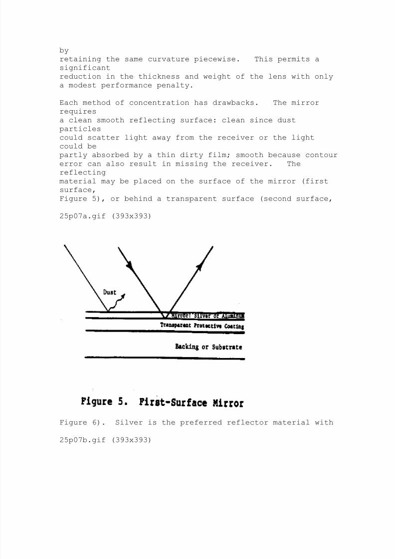
Each method of concentration has drawbacks. The mirror
requires
a clean smooth reflecting surface: clean since dust
particles
could scatter light away from the receiver or the light
could be
partly absorbed by a thin dirty film; smooth because contour
error can also result in missing the receiver. The
reflecting
material may be placed on the surface of the mirror (first
surface,
Figure 5), or behind a transparent surface (second surface,
25p07a.gif (393x393)
Figure 6). Silver is the preferred reflector material with
25p07b.gif (393x393)

8/2/2019 Understanding Concentrated Solar Power
http://slidepdf.com/reader/full/understanding-concentrated-solar-power 13/49
aluminum second. Silver is very susceptible to degradation
by
moisture and airborne contaminants. Available protective
coatings
have not proven effective for silver in first surface
application.
Aluminum is more durable but less reflective.Second-surface mirrors have some energy loss due to
absorption of
light by the transparent surface, usually glass or plastic,
as
the light is incident and as it is reflected through the
material.
Low-iron glass is preferred over high-iron glass because
of reduced absorption of light. If plastic is used, it
must be
stabilized against degradation by the ultraviolet light of
the
sun.
Because of the greater thickness of the lens, the degree of
energy absorption is higher than that of the second surface
mirror. The Fresnel lens, which can be made much thinner
than a
standard lens, has less energy loss due to energy
8/2/2019 Understanding Concentrated Solar Power
http://slidepdf.com/reader/full/understanding-concentrated-solar-power 14/49
absorption than
the standard lens.
The lens surface must also be clean and smooth for the same
reasons as for the mirror. Fresnel lens performance is
enhanced
when the vertical portion has little or no slope error.
Plastics
can be formed to produce Fresnel lens of higher quality and
less
cost than with glass. However, plastic lenses tend to
deteriorate
under ultraviolet light and must be stabilized.
Point, Line, or Non-Focusing
One criterion for selection of a specific concentrator is
thedegree of concentration and hence temperature that is to be
achieved. As a rule, concentrating energy onto a point
produces
high to very high temperature; and onto a line, moderate to
high
temperature. Non-focusing concentrators produce low to
moderate
temperature.
Point. The parabolic dish reflector (Figure 7) utilizes the
25p08.gif (393x393)

8/2/2019 Understanding Concentrated Solar Power
http://slidepdf.com/reader/full/understanding-concentrated-solar-power 15/49
optical properties of the parabolic curved surface to
concentrate
direct light to the focal point. The dish geometry is
familiar being used for automobile headlights, searchlights,
radar, and to receive transmissions from broadcast
satellites.
Standard circular and Fresnel lenses are also point focus
concentrators.
The Fresnel lens has been utilized in conjunction with
photovoltaic cells in several test installations in the
United
States and abroad.
The overlapping images from many flat mirrors can be
considered
the equivalent of point focusing. The focal shape is not
a point
but rather the finite image of the sun further broadened by
the
characteristics of the reflector material and various
errors in
manufacture and in the precision of image overlap. Figure
8

8/2/2019 Understanding Concentrated Solar Power
http://slidepdf.com/reader/full/understanding-concentrated-solar-power 16/49
25p09a.gif (393x393)
illustrates the central receiver concept wherein heliostats
(flat
or slightly curved mirrors mounted on tracking devices)
redirectthe sun's rays toward a receiver atop a tower. A 10-
megawatt
electrical generating plant employing this principle has
been
successfully operated in California since 1982.
Line. The parabolic trough (Figure 9) is an example of
line focus
25p09b.gif (393x393)

8/2/2019 Understanding Concentrated Solar Power
http://slidepdf.com/reader/full/understanding-concentrated-solar-power 17/49
optics. The incident direct radiation is reflected from
the
trough to the focal line the length of the trough. To
maximize
energy collection the trough is designed to track the sun.
The
trough may be oriented with the focal line running east-west,
north-south, or north-south with simultaneous tilt toward
the sun
(polar mount).
Each orientation has its own seasonal and yearly collection
characteristics.
No one orientation is universally preferred (i.e.,
is more cost-effective).
The standard and Fresnel lenses can be fabricated in linear
form
(Figure 10) with the same cross section as the circular
lens but
25p10.gif (534x534)

8/2/2019 Understanding Concentrated Solar Power
http://slidepdf.com/reader/full/understanding-concentrated-solar-power 18/49
now producing a focal line instead of a focal point.
Plastic
linear Fresnel lenses of good quality can easily be
produced by
extrusion.
The hemispherical bowl (Figure 11) is another example of
linear
25p11a.gif (540x540)

8/2/2019 Understanding Concentrated Solar Power
http://slidepdf.com/reader/full/understanding-concentrated-solar-power 19/49
focal optics. Unlike the trough or lens, two-axis tracking
is
mandatory. The hemispherical bowl is always fixed, and the
receiver
does the tracking. The focal line falls on the line
connecting
the center of the sphere with the sun. The focal line is
restricted to the lower half of the radius by the optical
properties
of the bowl. Because some rays reach the focal line withonly one reflection and others require multiple
reflections, the
intensity is not uniform along the length of the focal line.
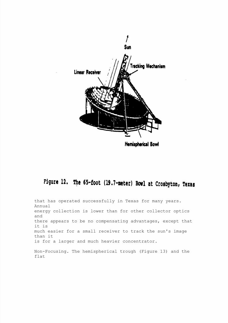
Figure 12 shows a 65-foot (19.7-meter) diameter
experimental bowl
25p11b.gif (600x600)
8/2/2019 Understanding Concentrated Solar Power
http://slidepdf.com/reader/full/understanding-concentrated-solar-power 20/49
that has operated successfully in Texas for many years.
Annual
energy collection is lower than for other collector optics
and
there appears to be no compensating advantages, except that
it ismuch easier for a small receiver to track the sun's image
than it
is for a larger and much heavier concentrator.
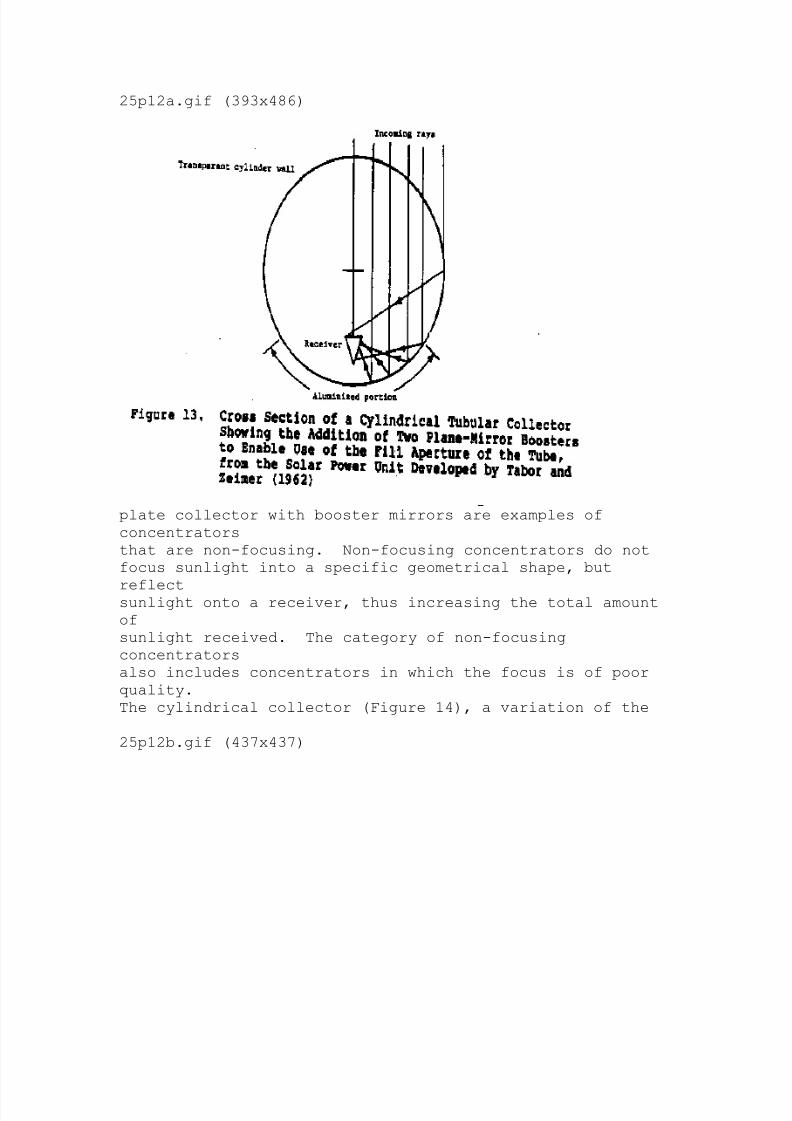
Non-Focusing. The hemispherical trough (Figure 13) and the
flat
8/2/2019 Understanding Concentrated Solar Power
http://slidepdf.com/reader/full/understanding-concentrated-solar-power 21/49
25p12a.gif (393x486)
plate collector with booster mirrors are examples of
concentrators
that are non-focusing. Non-focusing concentrators do not
focus sunlight into a specific geometrical shape, but
reflectsunlight onto a receiver, thus increasing the total amount
of
sunlight received. The category of non-focusing
concentrators
also includes concentrators in which the focus is of poor
quality.
The cylindrical collector (Figure 14), a variation of the
25p12b.gif (437x437)

8/2/2019 Understanding Concentrated Solar Power
http://slidepdf.com/reader/full/understanding-concentrated-solar-power 22/49
hemispherical trough, is of interest because the entire
cylinder
may be fabricated with inexpensive, inflatable plastic.
A simple method of achieving a modest increase inconcentration
on a large area is to use booster mirrors in conjunction
with a
flat plate collector (Figure 15). Before noon the mirrors
face
25p13a.gif (437x540)

8/2/2019 Understanding Concentrated Solar Power
http://slidepdf.com/reader/full/understanding-concentrated-solar-power 23/49
east; after noon they face west. The energy collection
advantage
of boosters for a flat plate collector is shown in Figure
16.
25p13b.gif (437x437)

8/2/2019 Understanding Concentrated Solar Power
http://slidepdf.com/reader/full/understanding-concentrated-solar-power 24/49
Fixed or Tracking Concentrators
Maximum energy collection on a daily or annual basis
requirestracking of the sun (or the sun's reflected image) since
concentrators,
particularly those capable of high concentration, utilize
only direct radiation. Thus a parabolic dish, when pointed
at the sun, has reflected rays passing through the focus.
As the
sun moves, some of the reflected rays will miss the focus
and, in
time, all will miss the focus. The dish must be moved to
maintain
the reflected rays at the focus. The central receiver,parabolic dish, parabolic trough, standard lens, and
Fresnel lens
are examples of tracking concentrator systems.
The hemispherical bowl likewise must continuously track the
sun.
Large bowls are too unwieldly to move. Thus, the receiver

8/2/2019 Understanding Concentrated Solar Power
http://slidepdf.com/reader/full/understanding-concentrated-solar-power 25/49
is
moved continuously instead. It tracks the focal line of the
sphere (the reflected image of the sun) throughout the day.
Like the hemispherical bowl, the Russell concentrator is
fixed
and the receiver must track the sun's image (Figure 17).
This
25p14.gif (393x486)
concentrator consists of long narrow mirrors whose centers
all
fall on the perimeter of a circle. The mirrors are
oriented so
that all reflected images focus on a point on the same
perimeter.
As the sun moves the focus moves along the perimeter.
The Winston collector is usually considered a non-tracking
concentrator.
Its energy collection can be increased by tracking. As
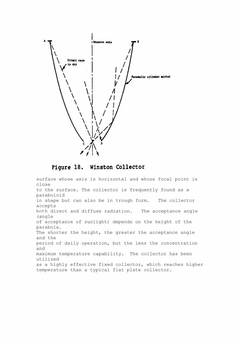
a trough-type collector (Figure 18), it consists of a
parabolic
25p15.gif (486x486)
8/2/2019 Understanding Concentrated Solar Power
http://slidepdf.com/reader/full/understanding-concentrated-solar-power 26/49
surface whose axis is horizontal and whose focal point isclose
to the surface. The collector is frequently found as a
paraboloid
in shape but can also be in trough form. The collector
accepts
both direct and diffuse radiation. The acceptance angle
(angle
of acceptance of sunlight) depends on the height of the
parabola.
The shorter the height, the greater the acceptance angle
and theperiod of daily operation, but the less the concentration
and
maximum temperature capability. The collector has been
utilized
as a highly effective fixed collector, which reaches higher
temperature than a typical flat plate collector.

8/2/2019 Understanding Concentrated Solar Power
http://slidepdf.com/reader/full/understanding-concentrated-solar-power 27/49
Fixed or Tracking Receivers
The central receiver and parabolic trough have fixed
receivers,
due to the optical characteristics of the systems. The
parabolic
dish receiver is usually positioned at the focus so as to
move
with the dish as the dish tracks the sun. Neither the
bowl nor
the Russell collector track the sun, hence their receivers
must
track the sun's image. The Winston collector, the
cylindrical
collector, and the flat plate collector with booster
mirrors are
normally utilized in fixed position and with fixed
receivers. Theflat plate is, of course, both the collector and the
receiver.
Other Fixed Concentrators
There are many ingenious concentrators that work quite well
and
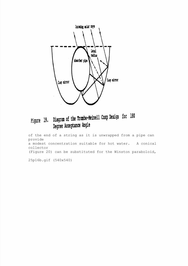
can be cost effective in some applications. The cusp
collector
(Figure 19), whose surface geometry is the locus of the
position
25p16a.gif (486x486)
8/2/2019 Understanding Concentrated Solar Power
http://slidepdf.com/reader/full/understanding-concentrated-solar-power 28/49
of the end of a string as it is unwrapped from a pipe can
providea modest concentration suitable for hot water. A conical
collector
(Figure 20) can be substituted for the Winston paraboloid,
25p16b.gif (540x540)

8/2/2019 Understanding Concentrated Solar Power
http://slidepdf.com/reader/full/understanding-concentrated-solar-power 29/49
gaining simplicity of manufacture with some performance
penalty.
Similarly, flat reflectors can substitute for the parabolic
sides
of the Winston trough collector.
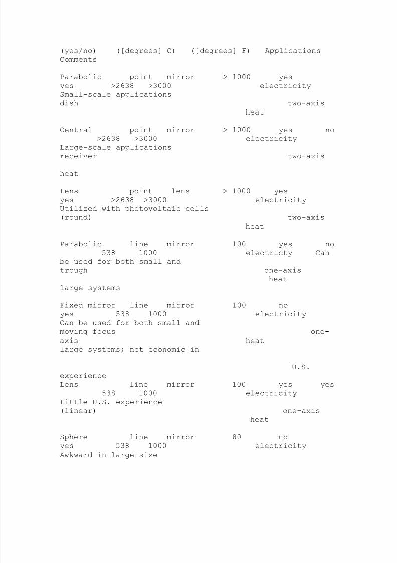
Table 1 summarizes the characteristics and potential uses
of the
concentrators described above.
Table 1. Classification of Concentrators
Type Sun's
Tracking Capability of
Type of of Lens or Concen- Tracking
Receiver Temperature Typical
Concentrator Focus Mirror tration (yes/no)
8/2/2019 Understanding Concentrated Solar Power
http://slidepdf.com/reader/full/understanding-concentrated-solar-power 30/49
(yes/no) ([degrees] C) ([degrees] F) Applications
Comments
Parabolic point mirror > 1000 yes
yes >2638 >3000 electricity
Small-scale applications
dish two-axis
heat
Central point mirror > 1000 yes no
>2638 >3000 electricity
Large-scale applications
receiver two-axis
heat
Lens point lens > 1000 yes
yes >2638 >3000 electricityUtilized with photovoltaic cells
(round) two-axis
heat
Parabolic line mirror 100 yes no
538 1000 electricty Can
be used for both small and
trough one-axis
heat
large systems
Fixed mirror line mirror 100 no
yes 538 1000 electricity
Can be used for both small and
moving focus one-
axis heat
large systems; not economic in
U.S.
experience
Lens line mirror 100 yes yes
538 1000 electricityLittle U.S. experience
(linear) one-axis
heat
Sphere line mirror 80 no
yes 538 1000 electricity
Awkward in large size
8/2/2019 Understanding Concentrated Solar Power
http://slidepdf.com/reader/full/understanding-concentrated-solar-power 31/49
two-
axis
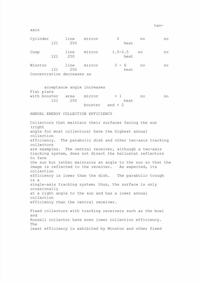
Cylinder line mirror 2 no no
121 250 heat
Cusp line mirror 1.5-2.5 no no
121 250 heat
Winston line mirror 3 - 6 no no
121 250 heat
Concentration decreases as
acceptance angle increases
Flat plate
with booster area mirror > 1 no no
121 250 heatbooster and < 2
ANNUAL ENERGY COLLECTION EFFICIENCY
Collectors that maintain their surfaces facing the sun
(right
angle for most collectors) have the highest annual
collection
efficiency. The parabolic dish and other two-axis tracking
collectors
are examples. The central receiver, although a two-axistracking system, does not direct the heliostat reflectors
to face
the sun but rather maintains an angle to the sun so that the
image is reflected to the receiver. As expected, its
collection
efficiency is lower than the dish. The parabolic trough
is a
single-axis tracking system; thus, the surface is only
occasionally
at a right angle to the sun and has a lower annual
collectionefficiency than the central receiver.
Fixed collectors with tracking receivers such as the bowl
and
Russell collector have even lower collection efficiency.
The
least efficiency is exhibited by Winston and other fixed
8/2/2019 Understanding Concentrated Solar Power
http://slidepdf.com/reader/full/understanding-concentrated-solar-power 32/49
collectors
and receivers.
The theoretical annual efficiency of the three principal
concentrating
collectors utilized in the United States is 80 percent
for the dish, 60 percent for the central receiver, and 43
percent
for the parabolic trough on an annual basis. Collector
efficiency
is determined for the period extending from the beginning
of tracking when the sun climbs to 15 degrees above the
horizon
until tracking stops when the sun declines below 15 degrees
at
the end of the day. The efficiency depends on direct solar
radiation
and system optics.
Actual efficiency depends on mirror or lens surface
accuracy,
surface dust and film, energy absorption by lens or mirror,
the
properties of the reflecting, material, pointing accuracy,
effects
of temperature variations on these factors, weather--
including
clouds, dust and haze, and so on. The efficiency is
furtherreduced by receiver performance and receiver subsystem
design,
including care given to reduction of heat loss by
conduction,
convection, and radiation.
III. DESIGN VARIATIONS AND EXPERIENCE
PARABOLIC DISHES
A recent paper on the parabolic dish prepared by the JetPropulsion
Laboratory(*) describes nine designs sponsored by the U.S.
(*) V.C. Truscello, "Status of the Parabolic Dish
Concentrator,
Proceedings of the Energy Research and Development Agency
Conference

8/2/2019 Understanding Concentrated Solar Power
http://slidepdf.com/reader/full/understanding-concentrated-solar-power 33/49
on Concentrating Solar Collectors, Georgia Institute of
Technology,
September 26-28, 1977 (Washington, D. C.: U. S. Department
of Energy, undated, circa 1982-1983).
Department of Energy, eight privately-funded U.S. designs,
and
10 dishes developed by other countries. Although no two
dishes
are identical, they fall into four categories:
1. Rigid reflector. The reflective surface is
attached to
a rigid curved structure. This is the standard
(radar
type) structure (Figure 21).
25p20a.gif (437x437)
2. Pressure-stabilized membrane. The reflective
surface is
attached to a flexible membrane, which takes the

8/2/2019 Understanding Concentrated Solar Power
http://slidepdf.com/reader/full/understanding-concentrated-solar-power 34/49
shape
of a rigid, curved support structure by creation
of a
vacuum between the membrane and structure. The
intent
is to reduce cost by reducing weight of materials
of
construction (Figure 22).
25p20b.gif (486x486)
3. Fresnel lens or Fresnel mirror. The lens isbuilt up
from several narrow concentric parts; the mirror
is
a series of concentric reflective surfaces. The
intent
is to reduce cost by simplifying the compound
curvature

8/2/2019 Understanding Concentrated Solar Power
http://slidepdf.com/reader/full/understanding-concentrated-solar-power 35/49
of the paraboloid (Figure 23).
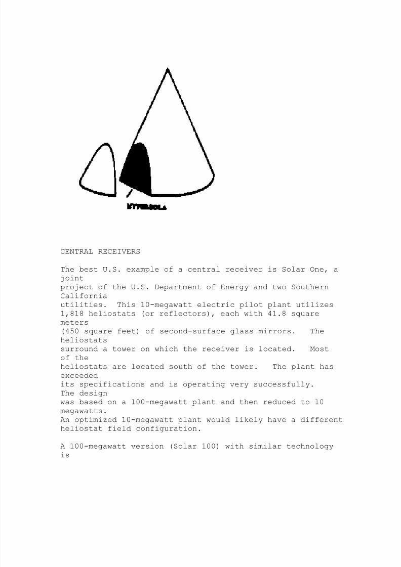
4. Secondary reflector. A second mirror, which may
be
hyperbolic(*) (cassegrain) or elliptic(**)
(gregorian),
reflects the rays from the parabolic reflector to a
receiver behind the parabola. The intent is to
eliminate
the heavy receiver structural demands on the
dish and also to provide easy access to the
receiver
for maintenance (Figure 24).
The rigid reflector has been the most popular since it
resembles
current radar technology. The Shenandoah project, a U.S.
Departmentof Energy demonstration project near Atlanta, Georgia,
deployed
114 7-meter-diameter dishes coated with a reflective film
to produce 399 [degrees] C (750 [degrees] F) steam. The
steam was used to generate
400 kilowatts of electricity and process steam at 9.70
kilograms
per square centimeter (138 pounds per square inch gauge
[psig])
for an adjacent knitwear factory. After some initial
problems,the system is now operating satisfactorily. The project
is a
joint effort of the U.S. Department of Energy, the local
power
company, and the knit-wear factory. Its goal was to
demonstrate
the viability of rigid-reflector collectors, not to be a
commercial
prototype.
(*) A curve formed by the section of a cone cutby a plane that makes a greater angle with
the base than the side of the cone makes.
(**) Oval-shaped.
25p19.gif (393x393)
8/2/2019 Understanding Concentrated Solar Power
http://slidepdf.com/reader/full/understanding-concentrated-solar-power 36/49
CENTRAL RECEIVERS
The best U.S. example of a central receiver is Solar One, a
joint
project of the U.S. Department of Energy and two Southern
Californiautilities. This 10-megawatt electric pilot plant utilizes
1,818 heliostats (or reflectors), each with 41.8 square
meters
(450 square feet) of second-surface glass mirrors. The
heliostats
surround a tower on which the receiver is located. Most
of the
heliostats are located south of the tower. The plant has
exceeded
its specifications and is operating very successfully.
The design
was based on a 100-megawatt plant and then reduced to 10
megawatts.
An optimized 10-megawatt plant would likely have a different
heliostat field configuration.
A 100-megawatt version (Solar 100) with similar technology
is
8/2/2019 Understanding Concentrated Solar Power
http://slidepdf.com/reader/full/understanding-concentrated-solar-power 37/49
being considered by the utilities, assuming government
investment
credits are provided. Without these financial incentives,
the
plant would not be economical in the United States due to
falling
oil prices. However, such a plant may be economical in
other
countries with high energy costs.
Heliostats have evolved through a series of designs that
reduced
the initial weight of over 97.6 kilograms/square meter (20
pounds/square foot) to about 39 kilograms/square meter (8
pounds/square
foot). Over 20 heliostat designs have been constructed and
tested. The current preference is for a second-surface
glassmirror on a glass backing. The U.S. Department of Energy's
Solar
Energy Research Institute is developing a lightweight
reflector
(plastic/silver/plastic), which promises to drastically
reduce
the cost of heliostats. When developed, the material may
be of
interest for use in less-industrialized countries.
Heliostat size is governed by rigidity and wind loadrequirements.
Due to the present cost elements of heliostats (which are
influenced by the fact that every heliostat needs its own
tracking
system), in the United States, system designs favor large
heliostats. The distribution of cost elements may vary in
other
countries. While only larger central receivers are likely
to be
economical in the United States, some advanced developing
countriesmay be able to utilize the smaller Solar One technology
economically.
LENSES
Circular lenses, whether standard or Fresnel, tend to be
limited

8/2/2019 Understanding Concentrated Solar Power
http://slidepdf.com/reader/full/understanding-concentrated-solar-power 38/49
in size, much like the parabolic dish. Size is also
limited by
current fabrication capabilities. Small glass lenses for
cameras
and spotlights are available, as are larger plastic lenses.
But
a 7-meter diameter lens (a size comparable to the Shenandoah
dish) is certainly not widely available either in glass or
plastic.
In large sizes, a glass lens would be very heavy; plastic,
probably in a Fresnel design, is likely to be the only
practical
lens, if available. Linear Fresnel lenses may offer the
advantage
of being fabricable in both small and large widths and
lengths.
PARABOLIC TROUGHS
A significant number of parabolic troughs have been
designed,
built, and tested, primarily with private funds. Many
types are
available on the market. Troughs differ in their reflective
materials, structural materials, receiver concepts, etc.
The
attainable temperature reaches about 540 [degrees] C (1000
[degrees] F). The designs
vary with intended temperature application, since surfaceerror,
tracking error, and receiver losses assume considerable
importance
for a high temperature design.
Troughs have been utilized by many federal demonstration
projects
to provide process heat for industrial applications and to
supply
vapor for suitable small engines (e.g., irrigation pump
devices).All designs had initial problems, usually with materials
and nonsolar
hardware. After repair or modification, operation was
reliable
and successful. Many federally-funded projects tended to
be shut down when they ended and rarely restarted because
of lack

8/2/2019 Understanding Concentrated Solar Power
http://slidepdf.com/reader/full/understanding-concentrated-solar-power 39/49
of sustained interest by the user. An excellent source of
information
on private trough manufacturers is the Solar Energy
Industries
Association (SEIA) in Washington, D.C.
Troughs may be attractive because of their relative
simplicity.
Because their surface curvature is singular, not compound
as for
dishes, troughs are more easily fabricated. A second-
surface
reflective plastic with adhesive backing can be easily
placed on
the curved substrate. A simple pipe or tube will serve
adequately
as the receiver although various simple techniques, such as
aglass vacuum jacket around the receiver tube, will enhance
performance.
Single-axis tracking is less complex than two-axis
tracking.
IV. SPECIAL TOPICS
RECEIVERS
The concentrated sunlight must be converted to a usefulform of
energy, usually heat. If desired, heat can be converted to
electricity
by means of an engine and generator. The receiver should
be designed to minimize heat loss. Heat loss occurs
through
radiation to a cooler object; through convection currents
created
by heating air in contact with the hot receiver surface; and
through conduction from the hot parts of the receiver to
colderparts and to attached structural members and insulation.
Heat retention by the receiver is enhanced by covering the
receiver
with a selective coating which will absorb virtually all
the concentrated radiation but will reradiate comparatively
little energy. Furthermore, since the total energy radiated
depends directly on the radiating area, the receiver
8/2/2019 Understanding Concentrated Solar Power
http://slidepdf.com/reader/full/understanding-concentrated-solar-power 40/49
surface area
should be minimized. Convection can be reduced by
preventing the
build-up of air currents that remove air heated by the
receiver
and provide the receiver with colder air for continued heat
loss.
A transparent window (glass or plastic depending on
temperature)
can reduce air currents.
The window introduces other heat loss and heat gain effects.
Some energy will be reflected from the front surface and
rear
surface of the window and never reach the receiver.
Additional
energy will be absorbed by the window and not reach the
receiver.The inner surface of the window may be coated with a heat
mirror
such as tin oxide, which reduces the radiation loss by
reflecting
radiated energy back to the receiver. Etching of the
outer surface
of a glass window reduces the reflection from the surface.
Insulation serves to reduce convection and radiation losses
from
parts of the receiver outside the path of the incomingradiation.
Conduction loss is reduced by decreasing the cross-section
of
structures in direct contact with the receiver, and using
poor
heat conductors for these structures where possible.
Creating a
vacuum between the window and the receiver will further
reduce
convection and conduction losses.
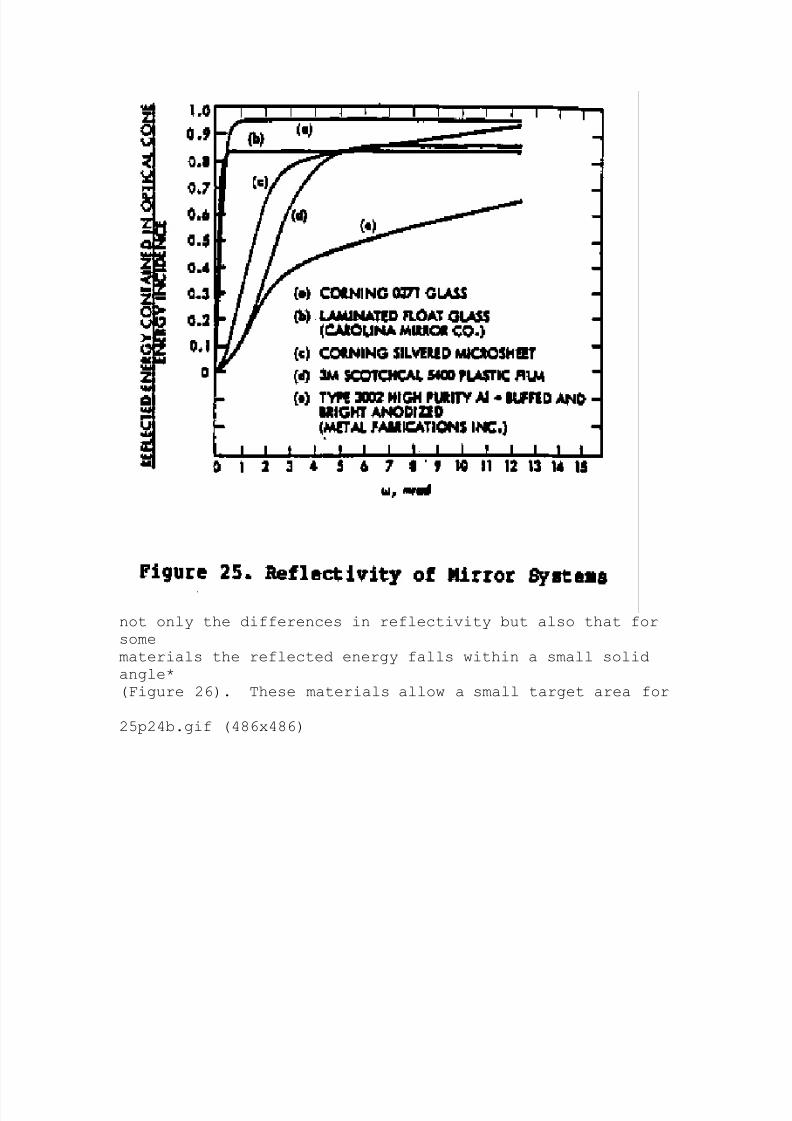
Figure 25 shows the reflectivity of several mirror systems.
Note
25p24a.gif (540x540)
8/2/2019 Understanding Concentrated Solar Power
http://slidepdf.com/reader/full/understanding-concentrated-solar-power 41/49
not only the differences in reflectivity but also that for
some
materials the reflected energy falls within a small solid
angle*
(Figure 26). These materials allow a small target area for
25p24b.gif (486x486)

8/2/2019 Understanding Concentrated Solar Power
http://slidepdf.com/reader/full/understanding-concentrated-solar-power 42/49
receipt of the reflected rays. If a larger solid angle is
requiredto enclose the reflection, then a compromise between
target size and loss of reflected rays must be made.
Energy which
is not reflected is converted to heat at the reflecting
surface.
This may require positive cooling efforts to ease or
eliminate
thermal stress.
COST
Concentrator cost represents only one portion of the cost
of a
system. The cost of the quantity of heat delivered at the
required
temperature is the preferred method of determining cost.
For a given system, the cost per million kilowatt-hours, or
kWh

8/2/2019 Understanding Concentrated Solar Power
http://slidepdf.com/reader/full/understanding-concentrated-solar-power 43/49
(per million Btu) usually decreases as the total number of
kWh
(Btu) delivered increases, i.e., as system size increases.
Similarly,
the cost per million kWh (per million Btu) is likely to be
less at lower temperatures than at higher temperatures.
In general,
the higher the concentration and complexity, the higher the
cost.
(*) If you have an angle, one side of which is vertical and
the
other side not vertical, and that side is rotated around
the vertical
(maintaining the same angle), the angle created is called
the solid angle.
Cost is frequently represented by purchase price but notalways.
Sellers may reduce selling price to penetrate a market, to
expand
market share, to anticipate future manufacturing economies
and
cost reductions, and to limit or exclude potential
competition.
Sellers with a monopoly or a preferred position may sell at
higher than reasonable rates. Sellers faced with unknown
or
indeterminate risks and liabilities for the product willtry to
transfer the risk to the purchaser through higher prices or
other
means.
In the United States, many solar energy systems are cost
effective
only because of federal and state tax policies to aid the
solar energy industry. These systems cost two to five
times more
than competing energy systems. However, energy costs inmany
less-developed countries are several times greater than in
the
United States, and therefore solar systems may be cost
effective
in those countries.
8/2/2019 Understanding Concentrated Solar Power
http://slidepdf.com/reader/full/understanding-concentrated-solar-power 44/49
In the United States, the cost of a solar thermal electric
system
utilizing relatively new technology and incorporating
research
and development costs would range from $10 to about $30 per
watt.
The central receiver experiment in California (Solar One)
cost
about $15 per watt; a proposed 100-megawatt plant
incorporating
the lessons of Solar One and the economies of a ten-fold
increase
in size is anticipated to cost about $4 per watt.
Heliostats were
about one-third of the total cost of Solar One, and are
expected
to be about one-half the cost of the large plant. (A
coal-firedelectric plant costs about $1.00-$1.40 per watt of installed
capacity.)
Studies of dish technologies indicate costs ranging to $50
per
watt for the system, with dish costs of one-third to one-
half of
the system cost. Dish technology is well behind heliostat
experience.
Parabolic troughs appear to cost about $538 per square
meter ($50 per square foot) at present with possiblereduction to
about $270 per square meter ($25 per square foot) with a
larger
market. Again, these costs reflect only one-third to one-
half the
system cost.
Of possible interest to developing countries is the class of
collectors using transparent plastic in cylindrical form
with the
reflector film partially located in the lower arc and a"black"
tube located at the focus. This type of collector appears
to
offer low cost. Some versions using an evacuated glass
tube with
an inner blackened copper tube in "once through" (straight
tube)
8/2/2019 Understanding Concentrated Solar Power
http://slidepdf.com/reader/full/understanding-concentrated-solar-power 45/49
8/2/2019 Understanding Concentrated Solar Power
http://slidepdf.com/reader/full/understanding-concentrated-solar-power 46/49
included
in any evaluation methodology for selection of cost-
effective
systems.
V. COMPARING THE ALTERNATIVES
Simple flat plate collectors are the most widely used and
most
cost-effective solar collectors. Their primary use is for
domestic
and commercial (e.g., hospitals, restaurants, etc.) hot
water
applications; however they may also be used in preheat
systems
for higher temperature applications. They can achieve a
temperature
of about 38 [degrees] C (100 [degrees] F) above the ambientby capturing sunlight,
converting sunlight to heat, and carefully minimizing
unwanted heat loss from the collector.
Flat plate (usually non-tracking) collectors are the
simplest to
fabricate. Simple, unsophisticated, functioning collectors
can
easily be built with simple tools. Care must be taken to
enhance
solar collection and prevent thermal losses. Careful useof local
materials to the maximum extent possible can reduce cost.
While
selective absorbers enhance performance and yield higher
temperature,
almost any "black" surface will perform adequately. Some
simple, low-cost flat plate collectors may be better than
concentrators
for temperatures below 93 [degrees] C (200 [degrees] F),
particularly in
less-industrialized countries. Expectations of betterperformance
for flat plate (non-concentrating) collectors over
concentrating
collectors, for the same temperature application, have not
been
verified in practice. The expectations were based on
utilization
8/2/2019 Understanding Concentrated Solar Power
http://slidepdf.com/reader/full/understanding-concentrated-solar-power 47/49
of both direct and diffuse radiation by flat plate
collectors and
use of only direct radiation by concentrators.
BIBLIOGRAPHY/SUGGESTED READING LIST
Reports and Conference Proceedings
Dougherty, D.A. Line-Pocus Receiver Heat Losses. SERI/TR-
632-868.
Golden, Colorado: Solar Energy Research Institute,
July 1982.
Murphy, L.M. Technical and Cost Potential for Lightweight,
Stretched-Membrane Heliostat Technology. SERI/TP-
253-2070.
Golden, Colorado: Solar Energy Research Institute,
January1984.
Scholten, W.B. A Comparison of Energy Delivery Capabilities
of
Solar Collectors. McLean, Virginia: Science
Applications,
Inc., 1983.
Solar Energy Research Institute. Solar Thermal Technology
Annual
Evaluation Report, Fiscal Year 1983. Golden,Colorado: Solar
Energy Research Institute, August 1984.
Truscello, V.C. "Status of the Parabolic Dish Concentrator."
Proceedings of the Energy Research and Development
Agency
Conference on Concentrating Solar Collectors. Georgia
Institute
of Technology, September 26-28, 1977. Washington,
D.C.:
U.S. Department of Energy, undated (circa 1982-1983).
U.S. Department of Energy. Solar Parabolic Dish Annual
Technology
Evaluation Report, Fiscal Year 1982. DOE/JPL1060-63.
Washington,
D.C.: U.S. Department of Energy, September 15, 1983.
8/2/2019 Understanding Concentrated Solar Power
http://slidepdf.com/reader/full/understanding-concentrated-solar-power 48/49
U.S. Department of Energy/Sandia Laboratories.
Proceedings of the
Line-Focus solar Thermal Energy Technology Development
Conference,
A Seminar for Industry (September 9-11, 1980).
Washington, D.C.: U.S. Department of Energy, September
1980.
Books
Duffie, J.A., and Beckman, W.A. Solar Engineering of
Thermal Processes.
New York, New York: John Wiley and Sons, 1980.
Kreith, F., and Kreider, J.F. Principles of Solar
Engineering.
Washington, D. C.: Hemisphere Publishing Corp., 1978.
Lunde, P.J. Solar Thermal Engineering. New York, New
York: John
Wiley and Sons, 1980.
Meinel, A.B., and Meinel, M.P. Applied Solar Energy.
Reading,
Massachusetts: Addison-Wesley Publishing Co., 1976.
SOURCES OF INFORMATION
Government Printing Office Many governmentreports
Washington, D.C. 20402 USA are available
through
this office.
Jet Propulsion Laboratory
4800 Oak Grove Drive
Pasadena, California 91103 USA
National Technical Information Source of most
federalService project reports
5285 Port Royal Road
Springfield, Virginia 22161 USA
Solar Energy Industries Association List of
manufacturers
1717 Massachusses Avenue N.W. with companies and

8/2/2019 Understanding Concentrated Solar Power
http://slidepdf.com/reader/full/understanding-concentrated-solar-power 49/49
Washington, D.C. 20036 USA systems
Solar Energy Research Institute Information on all
1617 Cole Boulevard thermal systems
Golden, Colorado 80401 USA
U.S. Department of Energy Information on all
Office of Thermal Systems thermal systems
1000 Independence Avenue, S.W.
Washington, D.C. 20585 USA
========================================
========================================
Related Documents