Underground System Design TADP 547 Basic Cable Design III Presentation 4.3 Instructor: Frank Frentzas

Welcome message from author
This document is posted to help you gain knowledge. Please leave a comment to let me know what you think about it! Share it to your friends and learn new things together.
Transcript

Underground System Design
TADP 547
Basic Cable
Design III
Presentation 4.3
Instructor: Frank Frentzas
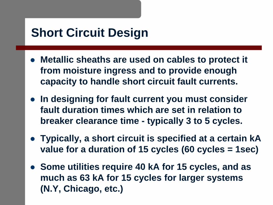
Short Circuit Design
Metallic sheaths are used on cables to protect it
from moisture ingress and to provide enough
capacity to handle short circuit fault currents.
In designing for fault current you must consider
fault duration times which are set in relation to
breaker clearance time - typically 3 to 5 cycles.
Typically, a short circuit is specified at a certain kA
value for a duration of 15 cycles (60 cycles = 1sec)
Some utilities require 40 kA for 15 cycles, and as
much as 63 kA for 15 cycles for larger systems
(N.Y, Chicago, etc.)

Short Circuit Calculations
To adequately design the metallic sheath to the required
fault current level the following formula (ICEA P45-482
standard) is used:
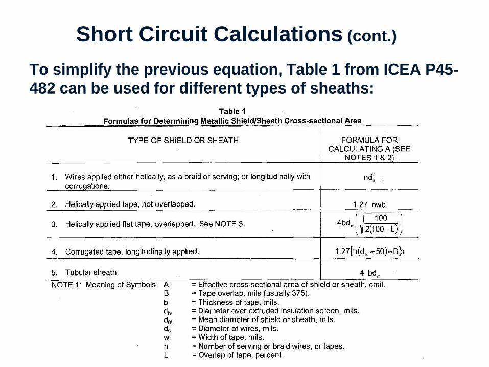
Short Circuit Calculations (cont.)
To simplify the previous equation, Table 1 from ICEA P45-
482 can be used for different types of sheaths:

Sheath Design
For some high resistance sheath designs (lead-alloy,
copper, aluminum foils, as well as stainless steel
sheaths) that require additional fault current capacity a
layer of copper wires is typically added to the cable
design.
Copper
Foil
Copper
wires

Cable Expansion
When the cable system is in operation and carrying load
the conductor’s temperature will increase with load, which
causes the cable to expend. Thermal expansion can be
calculated by the following:
DL=(a)(L)(DT)
DL- change in length (total expansion)
a-coefficient of expansion
DT- change in temperature (T2-T
1)
Coefficient of
expansion
(a)
Aluminum 0.0000236
Carbon Steel 0.0000110
Copper 0.0000168
Lead 0.0000293
Stainless Steel (304) 0.0000170
Cable Expansion (cont.)
Field values of thermal expansion are not the same
as calculated value.
Field experience indicate the expansion is less than
calculated values.
Thermal expansion must be addressed when
designing a cable system, and consideration of the
following variables to determine the best and most
cost effective design solution.

Key Variables – Cable Expansion
Key variables that influence the design include:
– Conduit size
– Manhole size
– Cable dimension
– Design and size of cable splice
– Cable supports
– Cable clamp design
– Route geometry
Conduit Size
Conduit size determined by cable diameter.
Common practice is to size duct diameter (id)
1.5x cable diameter. However, smaller ratios
have been used successfully.
For example, a 4” diameter cable will require a
6” duct.
Cable Expansion
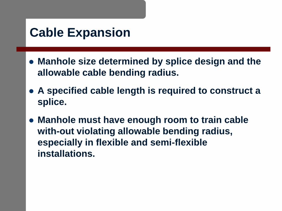
Manhole size determined by splice design and the
allowable cable bending radius.
A specified cable length is required to construct a
splice.
Manhole must have enough room to train cable
with-out violating allowable bending radius,
especially in flexible and semi-flexible
installations.
Handling Thermal Expansion
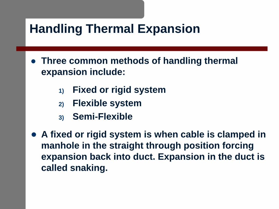
Three common methods of handling thermal
expansion include:
1) Fixed or rigid system
2) Flexible system
3) Semi-Flexible
● A fixed or rigid system is when cable is clamped in
manhole in the straight through position forcing
expansion back into duct. Expansion in the duct is
called snaking.
Cable Clamps
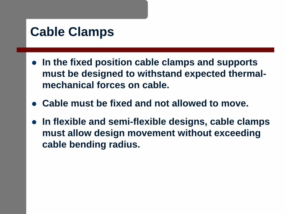
In the fixed position cable clamps and supports
must be designed to withstand expected thermal-
mechanical forces on cable.
Cable must be fixed and not allowed to move.
In flexible and semi-flexible designs, cable clamps
must allow design movement without exceeding
cable bending radius.
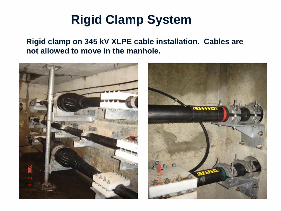
Rigid Clamp System
Rigid clamp on 345 kV XLPE cable installation. Cables are
not allowed to move in the manhole.
Flexible Clamp System
A flexible clamp system accommodates cable
expansion and contraction without violating
the allowable cable bending radius.
Flexible systems typically used at 138 kV and
below for systems with small conductor size.
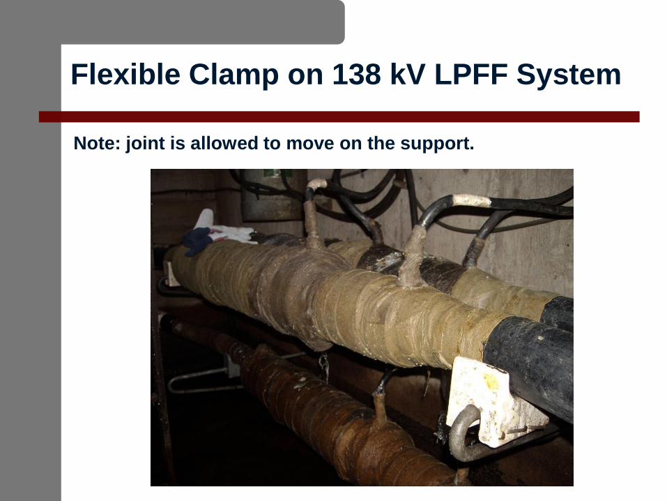
Flexible Clamp on 138 kV LPFF System
Note: joint is allowed to move on the support.
Semi-Flexible Clamp System
In a semi-flexible clamp system, a cable can
partially move to accommodate some cable
expansion with remainder being taken up in
duct without violating allowable cable
bending radius while the joint is locked down
and can only move as a unit.
Semi-flexible systems are typically used in
smaller manholes where expansion of the
cable is limited.
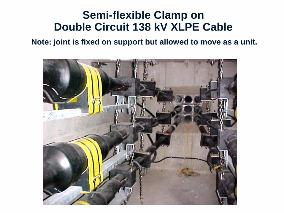
Semi-flexible Clamp on Double Circuit 138 kV XLPE Cable
Note: joint is fixed on support but allowed to move as a unit.
Cable Route
Route geometry or elevation is very important,
especially if on an incline slope.
An incline slope requires special restrains to
prevent cable from moving in direction of slope.
An “S” bend prior to entering manhole can
alleviate the forces from having to be controlled by
manhole clamping alone.
HPFF System Expansion
HPFF pipe type systems have three paper
insulated cables installed in a steel pipe. The
pipe is filled with dielectric fluid and
pressurized.
Thermal expansion takes place within the
pipe but the joints need to be restrained to
avoid excessive thermal mechanical bending,
which can lead to a failure.
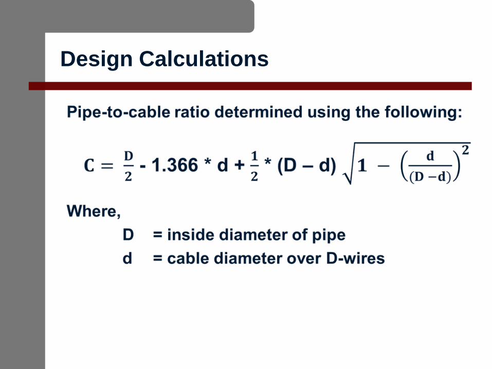
Design Calculations
Design Parameters
Another design perimeter when designing cable-to-
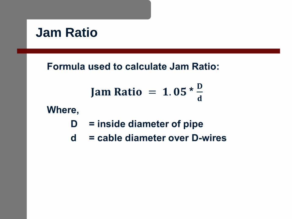
pipe ratios is the Jam Ratio.
Jam Ratio is clearance required to prevent cables
getting jammed during pulling.
If ratio of pipe inside diameter to cable diameter is
in range of 2.95 - 3.1, there is a chance cables will
jam during pulling.
You must, therefore, design the cable and pipe to
fall outside that range.
Jam Ratio
Other Joint Systems
Normal pipe type system joints typically restrained
by spiders (about four per joint, depending on
design).
Another type is the Anchor joint. They are used to
restrain cables from moving and are typically
employed on both sides of river crossings, in tunnel
shafts, or where the circuit is built on an incline.
In some applications, typically in tunnels, skid joints
are used to allow the joint to move during cable
expansion and contraction.
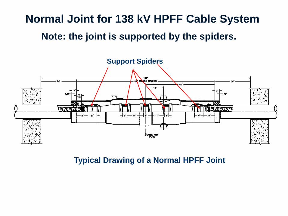
Normal Joint for 138 kV HPFF Cable System
Note: the joint is supported by the spiders.
Typical Drawing of a Normal HPFF Joint
Support Spiders
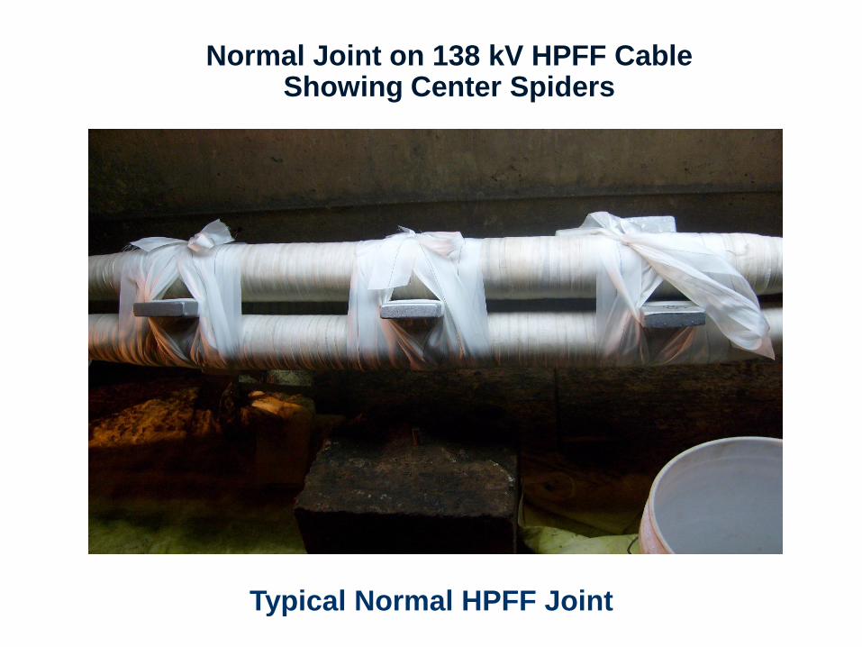
Normal Joint on 138 kV HPFF Cable Showing Center Spiders
Typical Normal HPFF Joint
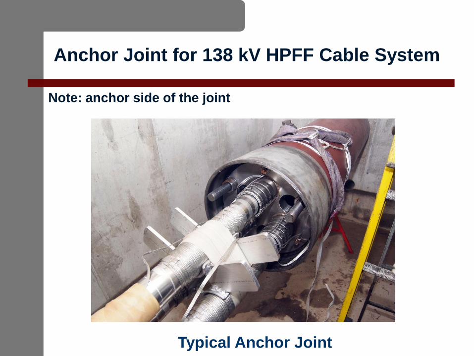
Anchor Joint for 138 kV HPFF Cable System
Note: anchor side of the joint
Typical Anchor Joint
Related Documents