1 Eneco gasspeicher Underground gas storage in salt cavern September 2009 Q.A.L.V Noordoven

Welcome message from author
This document is posted to help you gain knowledge. Please leave a comment to let me know what you think about it! Share it to your friends and learn new things together.
Transcript
1
EnecogasspeicherUndergroundgasstorageinsaltcavern
September2009
Q.A.L.VNoordoven

2
AbstractTheDutchnationalenergycompanyEnecoisintheprocessofimplementingalargeprojectinvolvingthestorageofgasinsaltcavernsinEpe,Germany.Forshort‐termgastradingandflexibilityinthegasmarketEnecointendtoleasetwocavernstill2030withanoptiontoleasetill2060.ThecavernsareleachedbySalzgewinnungsGeselschaftWestfalen(SGW).Thiscompanyhasproducedbrinefromthisareasincethe1972.Thetwocavernswillhaveageometricalvolumeof500000m3and400000m3,andwillbeoperatedbetween40and210bar,resultinginaworkinggasvolumeof170millionm3.Enecoexpectstheprojecttocontributetoanincreasedsecurityofsupplyandliquidityofthenorth‐WestEuropeangasmarket.Tocompletethisproject,EnecoGasspeicherteamaskedmetogiveacompleteoverviewofheproject.Andtogiveallparametersinvolvedinthisproject.Thispaperwilldescribetheprojectinsomemoredetail.

3
Tableofcontent:Enecogasspeicher.................................................................................................................................................. 1
Abstract ............................................................................................................................................................. 2 Introduction....................................................................................................................................................... 4
1.Solutionmining .................................................................................................................................................. 4 1.1Introduction:................................................................................................................................................ 4 1.2 Miningprocess:........................................................................................................................................ 4
2. Hydrocarbonstorage ..................................................................................................................................... 6 3. EnecoGasspeicher ......................................................................................................................................... 9
3.1introduction................................................................................................................................................. 9 3.2 Stratigraphy ........................................................................................................................................... 10 3.3 Wells ...................................................................................................................................................... 12 3.4 Installation ............................................................................................................................................. 13
4.1 Storageparameters ................................................................................................................................... 13 4.2Gashydrates .............................................................................................................................................. 15 Temperature.................................................................................................................................................... 16 4.3.Rockmechanicsinsalt.............................................................................................................................. 16
4.3.1.Creepofrocksalt .............................................................................................................................. 17 4.3.2.Primarycreep .................................................................................................................................... 18 4.3.3.Secondarycreep................................................................................................................................ 18
4.4Permeability .............................................................................................................................................. 18 4.5Cavernspacing........................................................................................................................................... 19 4.6Subsidence................................................................................................................................................. 20 4.7Storagepressure........................................................................................................................................ 20 4.8Cavernsabandonment .............................................................................................................................. 22
5 Conclusionsandrecommendations: ............................................................................................................. 23 6Data................................................................................................................................................................... 24 7References ........................................................................................................................................................ 25
4
IntroductionSinceJuly2004,marketliberalizationforgasaswellforelectricityiseffectiveforallgroupsofcustomers,includingresidentialcustomers.Distributioncompanies,likeEneco,andothershippersnowadaysimportgasfortheirownportfolios,whereasinthepre‐liberalizationerathedistributioncompaniespurchasedtheirgasrequirementsfromtheformerlyintegratedGasunie.(Hoelen,Q.,vanPijkeren,G.,Teuben,B.,Steenbergen,B.,Breuning,P.)Theenergycompaniescanusestoragefacilitieslikesaltcavernfortheirownflexibility.Enecoplanstousenaturalgasstorageforcommercialreasons;
• tooffermoretradingopportunities
• increaseprofitsbyshort‐termgastrading• Reducecostsrelatedwithpeakloaddemands
Thenaturalgasstorageisfacilitatedinasaltcavernleachedoutbysolutionmining.Inthisreportarelistedthevariousmethodsforsolutionmining,thestorageparameters,thelithologyandtherockmechanics.Alsoare
listedtheEnecoGasspeicherplanforundergroundgasstorageandsomerecommendations.
1.Solutionmining
1.1Introduction:
Miningistheprocessofextractingoreormineralsfromtheground.Solutionminingisaprocessofrecoveringminerals;itisprimaryusedforsaltminerals.Saltsolutionminingistheminingofvarioussaltmineralsbydissolvingthemwithwaterandpumpingtheresultingbrinetothesurface.Waterorundersaturatedbrineisinjectedthroughawelldrilledintoasaltbedlayertoetchoutacavernorvoid.Thebrineisextractedforprocessing.Itusuallytargetssaltsatdepthsgreaterthan400metersandupto2800metersintheBaradeelconsessionintheNetherlands.(Breunese,J.,vanEijs,R.,deMeer,S.,Kroon,I.)Atdepthsgreaterthan2000meterongoingsaltcreeptendtoreducecavernsize.
InChinabrinewellsareusedformorethan2000years,especiallyintheScechuanandYunnanprovinces.MarcoPoloreportedannualproductioninasingleprovinceofmorethan30000tons.Withbamboopoles
theyleachedshallowsaltformations.InLorraine,France,thefirstsimplewellsweresunkbyhandasearlyasintheyear858.Andby1830intheUSAthereweremorethan60brinewellsinoperationintheOhioregion.
Theadvantageofsolutionminingoverconventionalminingorsurfaceevaporationisthatproductqualityandtheextractingoperationisnotdependentofclimateorrockstrengthandisnotdangerousforpersonneland
equipment.Solutionminingcanexploitfoldedanddisturbedbedsordeeplyingstrata,conventionaltechniquesarenotcommonlyusedinthesesituations.
1.2 Miningprocess:Thedesignofasaltsolutionwellconsistsoftwoormorecolumnsofsteelpipes(figure1).Freshwaterneeded
forthesolutionprocessispumpedintothewelltocreateacavityinthetargetedsaltbyleaching,thefollowingleachingfluidscanbeused:
‐ Surfacewaterfromrivers‐ Wellwater‐ Seawater‐ Waterfromsewage/purificationplants‐ Undersaturatedbrinefromothercaverns‐ Condensatefromsaltproductionplants.

5
Theresultingbrineisthenreturnedtothesurfacefortheprocessingandrecovery.
Thefirststepinsolutionminingsaltistodrillaborehole,largeenoughfortherequiredpipesandcasings.
Solutionwellsarewiderthanoil,gasorwaterwells.Nearthesurfacetheboreholeisthewidest.Thesurfacecasingiscementedinplacetopreventanyleakageandcontaminationofgroundwater,alsotopreventablow
out.Thefinalcasingstringissetatsomedepthbelowthetopofthetargetsalt,sothatduringdissolutionasetthicknessofsaltremainsinplace.Insomewellsthereisanotherstringthatcontrolsthethicknessofthefluid
blanket.Afluidblanketisusuallypumpedintoasolutioncaverntopreventrapidupwardleachingandapossiblecollapseofthecavernroof.Blanketfluidisinertsoitdoesnotdissolvethetargetsalt.
Figure1a:Methodofdirectcirculation. Figure1b:Methodofindirectcirculation
Therearetwomethodsfordevelopingandshapingcavernsasseeninfigure1.
Inthedirectcirculationmethod,feedsolventisinjectedthroughthetubingstringanddissolvesthesaltatthebottomoftheformation.Thebrineisthendrawnoutthroughtheannularspacebetweenthetubingstring
andthefinalcasing.
Intheindirectcirculationmethodfreshwaterisinjectedbetweenthetubingandthecasing.Thissystemiscalledthe“topinjectionmethod”.Bythetopinjectionmethodthewaterentersthesaltdepositatthetopof
theformationandstartstodissolvethesaltneartheroof.Thesaltbrineflowsdownwardtothebottomofthetubingwhereasumpeffecthasbeenproducedbythepumpdrawingonthetubing.Thesumpisaleftoverof
thebrineproductionoftheinhomogeneousrocksalt.Thebrineispumpedfromthewellandthenitisreadytobeprocessed.
Underthedesignscenario,stringscanberotatedandraisedasthecaverngrowsandthebottomfillswithdebris.
Whenasingleholesolutionminingwellisfirstdrilled,theflowratethroughthecavityandupthepipeisussuallykeptverylowtomaintainhigherbrineconcentration.Aftersomeyearsthesurfaceareaandthecavity
volumeincrease,theextractedbrineflowcanberaised.
6
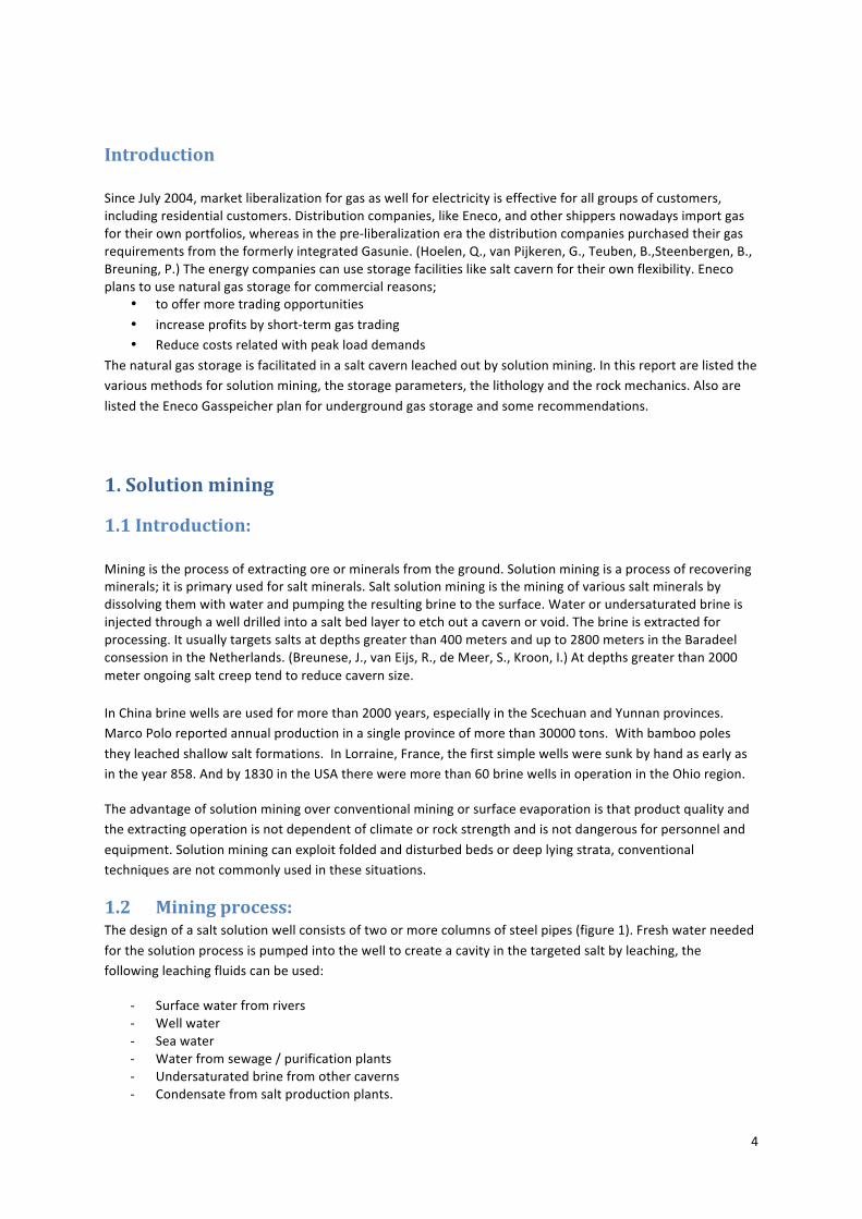
Leachingratesandthusconstructiontimesvarywiththeamountanddegreeofsalinityofthewaterinjected.Itiscommontofindthatforeverysevencubicmetersoffreshwaterinjected,avolumeofonem3isleached(Leith,2001).Leachingratesarenormallyexpressedastheamountofwaterorbrinecirculatedandcanreachratesof1600m3perday.IntheU.S.,leachingratesof320,000m3to400,000m3peryeararecommon(Leith,2001).Constructionratesforthetwo150,000m3solution‐minedcavernsatHuntorfinGermanywereanaverageofabout360m3ofsaltperday,atamaximumcirculationof600m3perhour.Eachcavernwascompletedinabout14monthsandittookafurtherfivemonthstoremovethebrinefromeachofthecaverns(Leith,2001).
Figure2:Constructionforsaltleaching.
Therearetwomethodsofsaltproduction.
Thesingle‐wellmethodofsolutionmininginvolvesthedrillingofasinglelargediameterdrillholeintoasaltformation.Acasingisusedintheholetostopthewallsfromcaving.Asecondtubingafsmallersizeisthen
placedinthecaseddrillhole.Thesinglewellmethodismostlyappliedfordeepersaltformations.
Thetwowellmethodofsolutionminingisbasedondrillingtwoidenticalwellsintoasaltbodyatadistancefromtenthstoseveralhundredsofmeters.Onewellisassignedasproductionwellandtheotherforinjection.
Severalwellmethodsstartsinthesamewayassingle‐wellmethodsolution,formingtwocaverns.Aftercompletion,highpressurewaterisappliedattheinjectionwellinordertocausehydraulicfracturing.The
brineisthendrawnfromtheproductionwell.Thevolumeofwaterwillonlyrisesotheproductionwilldecreasealso.Themainconcerninthestabilityofthelargecavernsisroofcontrol.Forthistypeofminingis
thedepthofsaltsolutionlimitedto300‐500meters.ThatiswhyinEpethismethodisnotused.
2. HydrocarbonstorageCrudeoil,LiquefiedPetroleumGas(LPG)andlighthydrocarbonscanbesafelystoredintheundergroundstoragefacilities.TheearliestoilstorageincavernswasinCanadaduringWorldWarII.In1949LPGwas
storedincavernsinTexas,USA.Inthepastdecadesnaturalgasisstoredin(salt)caverns,undergroundmines,aquifers,oil‐andgasfieldsinincreasingvolumes.ThefirststorageofnaturalgasinasaltcavernwasatUnity
Saskatchewan,intheUSA,in1959.Nowadaystherearemanysaltcavernsusedforoilandgasstorage

7
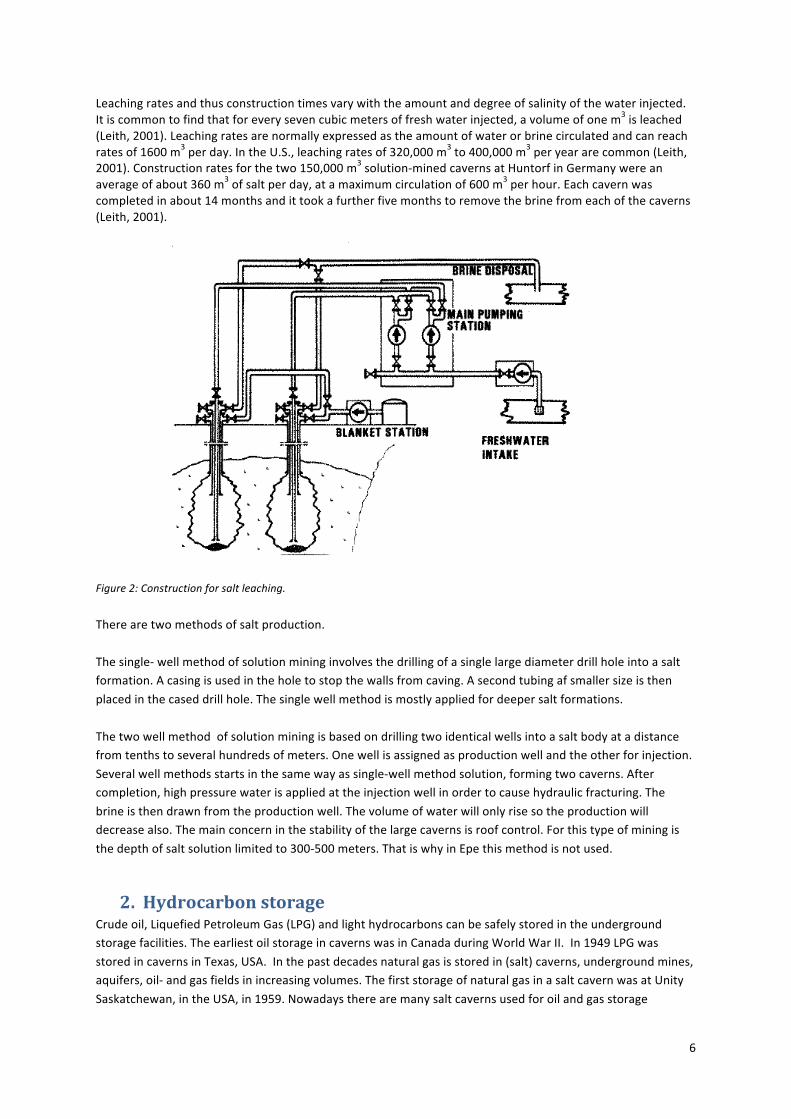
worldwide.Intotalover600undergroundgasstoragefacilitiesareused.Figure3.presentsasummaryoftheinstalledworkinggasvolume(106m3)bynations.
Saltdepositsareextensivelyusedforundergroundstorageofhydrocarbonsandotherproductsaswellasforwastedisposal.Thestoragecavernsinsaltdepositsareconstructedbythesolutionprocessdescribedinthe
previouschaptersolutionmining.Today’sbrineproducersarealsoawareofthepotentialstorageopportunities.Onereasontomakethecavernistheirbrinefeed,butontheotherhandtheyproducetight
cavernsuitableforstorage.Therenttheyreceivefromenergycompaniesareofgreatamounts.Thestoragecavernshavetomeetthecriterianecessarytoassurestableandtighthighpressure,subsurfacestorage
vessels.
Figure3:Undergroundstoragefacilitiesintheworld
Naturalgashasbecomeaprimesourceofenergyworldwide,especiallyinresidentialheatingandgas‐fired
powerplants.Traditionallythedemandfornaturalgasisusuallyhigherduringwinter,partlybecauseitisusedforheatinginresidentialandcommercialsettings.Storednaturalgasplaysavitalroleinensuringthatany
excesssupplydeliveredduringthesummermonthsisavailabletomeettheincreaseddemandofthewintermonths.However,withtherecenttrendtowardsnaturalgasfiredelectricgeneration,demandfornaturalgas
duringthesummermonthsisnowincreasing,becauseoftheneedofmoreelectricityinsummermonths,forairconditioningforexample.Naturalgasinstoragealsoservesasinsuranceagainstanyunforeseenaccidents,
naturaldisasters,orotheroccurrencesthatmayaffecttheproductionordeliveryofnaturalgas.Naturalgasstorageplaysavitalroleinmaintainingthereliabilityofsupplyneededtomeetthedemandsofconsumers.
8
Figure4:workinggasvolumebynations
GermanyisinthelastdecadestheleadingstoragecountryofWesternEurope.AccordingtoCEDIGAZ,Germanyhasanestimated713Bcfofworkingnaturalgasstoragecapacity,thelargestamountintheEUand
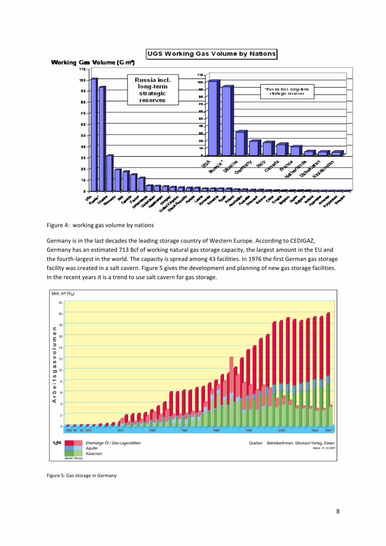
thefourth‐largestintheworld.Thecapacityisspreadamong43facilities.In1976thefirstGermangasstoragefacilitywascreatedinasaltcavern.Figure5givesthedevelopmentandplanningofnewgasstoragefacilities.
Intherecentyearsitisatrendtousesaltcavernforgasstorage.
Figure5:GasstorageinGermany
9
3. EnecoGasspeicher
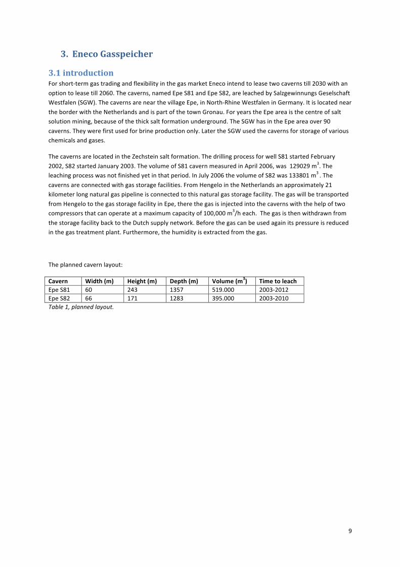
3.1introductionForshort‐termgastradingandflexibilityinthegasmarketEnecointendtoleasetwocavernstill2030withan
optiontoleasetill2060.Thecaverns,namedEpeS81andEpeS82,areleachedbySalzgewinnungsGeselschaftWestfalen(SGW).ThecavernsarenearthevillageEpe,inNorth‐RhineWestfaleninGermany.Itislocatednear
theborderwiththeNetherlandsandispartofthetownGronau.ForyearstheEpeareaisthecentreofsaltsolutionmining,becauseofthethicksaltformationunderground.TheSGWhasintheEpeareaover90
caverns.Theywerefirstusedforbrineproductiononly.LatertheSGWusedthecavernsforstorageofvariouschemicalsandgases.
ThecavernsarelocatedintheZechsteinsaltformation.ThedrillingprocessforwellS81startedFebruary
2002,S82startedJanuary2003.ThevolumeofS81cavernmeasuredinApril2006,was129029m3.Theleachingprocesswasnotfinishedyetinthatperiod.InJuly2006thevolumeofS82was133801m3.The
cavernsareconnectedwithgasstoragefacilities.FromHengelointheNetherlandsanapproximately21kilometerlongnaturalgaspipelineisconnectedtothisnaturalgasstoragefacility.Thegaswillbetransported
fromHengelotothegasstoragefacilityinEpe,therethegasisinjectedintothecavernswiththehelpoftwocompressorsthatcanoperateatamaximumcapacityof100,000m3/heach.Thegasisthenwithdrawnfrom
thestoragefacilitybacktotheDutchsupplynetwork.Beforethegascanbeusedagainitspressureisreducedinthegastreatmentplant.Furthermore,thehumidityisextractedfromthegas.
Theplannedcavernlayout:
Cavern Width(m) Height(m) Depth(m) Volume(m3) TimetoleachEpeS81 60 243 1357 519.000 2003‐2012EpeS82 66 171 1283 395.000 2003‐2010Table1,plannedlayout.

10
3.2 Stratigraphy
Figure6:PreliminarydepthmapoftheBaseZechsteinGroup(resultingfromtheSPBApilotmappingproject)
Thecommongoalofstratigraphystudiesisthesubdivisionoflayeredrocks.Itcantellusmuchabouttheprocessesaffectingthedepositionofsediments.
TheevaporaterocksoftheZechsteinformationwerelaiddownbytheZechsteinSea,anepicontinentalorepeiricseathatexistedintheGuadalupianandLopingianepochsofthePermianperiod.TheZechsteinSea
occupiedtheregionofwhatisnowtheNorthSea,pluslowlandareasofBritainandthenorthEuropeanplainofTheNetherlands,GermanyandPoland.InitsownerathecontinentwaslocatedneartheEarth'sequator
wherehightemperaturesandaridconditionsfacilitatedevaporationasseeninfigure7.
Figure7:LocationofthecontinentinthePermera.
11
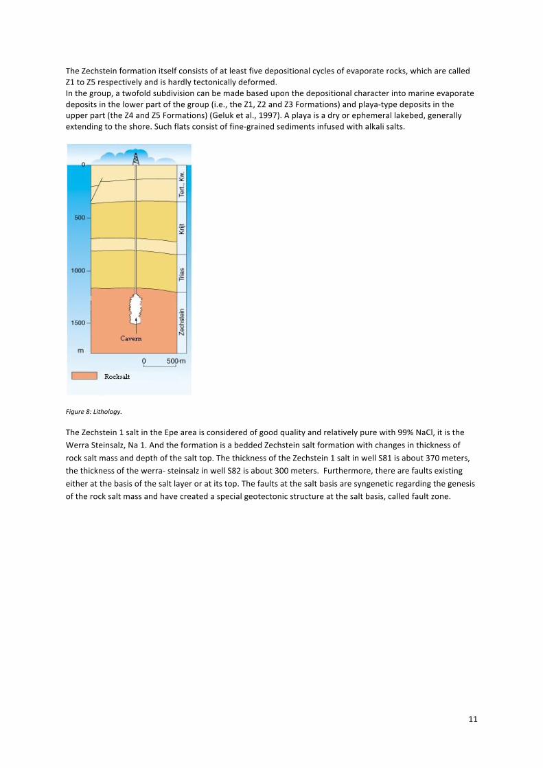
TheZechsteinformationitselfconsistsofatleastfivedepositionalcyclesofevaporaterocks,whicharecalledZ1toZ5respectivelyandishardlytectonicallydeformed.Inthegroup,atwofoldsubdivisioncanbemadebaseduponthedepositionalcharacterintomarineevaporatedepositsinthelowerpartofthegroup(i.e.,theZ1,Z2andZ3Formations)andplaya‐typedepositsintheupperpart(theZ4andZ5Formations)(Geluketal.,1997).Aplayaisadryorephemerallakebed,generallyextendingtotheshore.Suchflatsconsistoffine‐grainedsedimentsinfusedwithalkalisalts.
Figure8:Lithology.
TheZechstein1saltintheEpeareaisconsideredofgoodqualityandrelativelypurewith99%NaCl,itistheWerraSteinsalz,Na1.AndtheformationisabeddedZechsteinsaltformationwithchangesinthicknessof
rocksaltmassanddepthofthesalttop.ThethicknessoftheZechstein1saltinwellS81isabout370meters,thethicknessofthewerra‐steinsalzinwellS82isabout300meters.Furthermore,therearefaultsexisting
eitheratthebasisofthesaltlayeroratitstop.Thefaultsatthesaltbasisaresyngeneticregardingthegenesisoftherocksaltmassandhavecreatedaspecialgeotectonicstructureatthesaltbasis,calledfaultzone.

12
Figure9:ThicknessoftheZechsteinsaltformation
Inthenorthernandwesternpartofthedeposittherockmassatthesaltbasisischaracterizedbysignificantfaultzoneswithathrowofhundredandmoremeters.Theothercavernsshowthatthefaultsystemsatthebasisandabovethesaltdepositarenotthesame.Thereforethesaltrockmassitselfseemstobenotdestrengthenedbythefaultsystems.Theavailableborelogs(seeappendix)showsandstone,shaleandanhydrite.BelowtheWerra‐saltathickanhydritelayerexistswithanormalthicknessofabout100mandmore.Belowthisanhydritelayerthecarboniferousrockmassfollowswhichconsistsofchanginglayersofsandstone,siltstoneandclaystone.(Lux,Wermeling,Bannach)
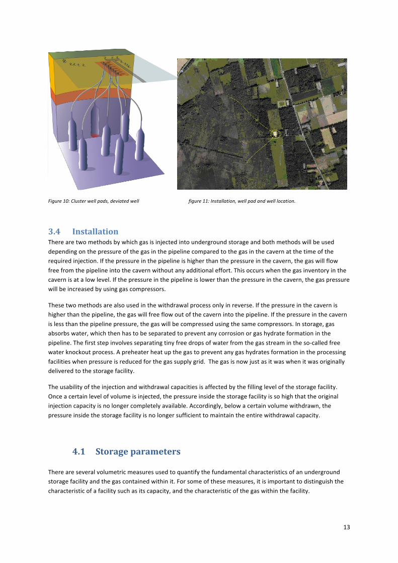
3.3 WellsTheEnecowells(S81andS82)areclusterwells.Clusterwellpadsallowmultiplecavernstobecreatedbeneathalargepadandarecheaperalternativetosinglewellpads.Theyhavealowerinfrastructurecostsandland
arearequirements.Howevercomparedtothesinglewellpads,theysufferfromlessflexibilityinongoingplanningandmaintenance.Casingsareacriticalfeatureinclusterpadwells,especiallyforhydrocarbon
storage.
13
Figure10:Clusterwellpads,deviatedwellfigure11:Installation,wellpadandwelllocation.
3.4 InstallationTherearetwomethodsbywhichgasisinjectedintoundergroundstorageandbothmethodswillbeused
dependingonthepressureofthegasinthepipelinecomparedtothegasinthecavernatthetimeoftherequiredinjection.Ifthepressureinthepipelineishigherthanthepressureinthecavern,thegaswillflow
freefromthepipelineintothecavernwithoutanyadditionaleffort.Thisoccurswhenthegasinventoryinthecavernisatalowlevel.Ifthepressureinthepipelineislowerthanthepressureinthecavern,thegaspressurewillbeincreasedbyusinggascompressors.
Thesetwomethodsarealsousedinthewithdrawalprocessonlyinreverse.Ifthepressureinthecavernishigherthanthepipeline,thegaswillfreeflowoutofthecavernintothepipeline.Ifthepressureinthecavern
islessthanthepipelinepressure,thegaswillbecompressedusingthesamecompressors.Instorage,gasabsorbswater,whichthenhastobeseparatedtopreventanycorrosionorgashydrateformationinthe
pipeline.Thefirststepinvolvesseparatingtinyfreedropsofwaterfromthegasstreamintheso‐calledfreewaterknockoutprocess.Apreheaterheatupthegastopreventanygashydratesformationintheprocessing
facilitieswhenpressureisreducedforthegassupplygrid.Thegasisnowjustasitwaswhenitwasoriginallydeliveredtothestoragefacility.
Theusabilityoftheinjectionandwithdrawalcapacitiesisaffectedbythefillinglevelofthestoragefacility.
Onceacertainlevelofvolumeisinjected,thepressureinsidethestoragefacilityissohighthattheoriginalinjectioncapacityisnolongercompletelyavailable.Accordingly,belowacertainvolumewithdrawn,the
pressureinsidethestoragefacilityisnolongersufficienttomaintaintheentirewithdrawalcapacity.
4.1 Storageparameters Thereareseveralvolumetricmeasuresusedtoquantifythefundamentalcharacteristicsofanundergroundstoragefacilityandthegascontainedwithinit.Forsomeofthesemeasures,itisimportanttodistinguishthe
characteristicofafacilitysuchasitscapacity,andthecharacteristicofthegaswithinthefacility.

14
Totalgascapacity: Themaximumvolumeofgasthatcanbestoredinanundergroundstorage facility.
Totalgasinstorage: Thevolumeofstorageintheundergroundfacilityataparticulartime.cushiongas: thevolumeofgasintendedaspermanentinventoryinastoragereservoirto
maintainadequatepressureanddeliverabilityratesthroughoutthewithdrawalseason.
Workinggascapacity: Thetotalgasstoragecapacityminuscushiongas.Workinggas: Thevolumeofgasinthereservoirabovethelevelofbasegas.
Workinggasisavailabletosell.Withdrawal: Mostoftenexpressedasameasureoftheamountofgasthatcanbe
delivered(withdrawn)fromastoragefacilityonadailybasis.The deliverabilityofagivenstoragefacilityisvariable,anddependsonfactors
suchastheamountofgasinthereservoiratanyparticulartime,the pressurewithinthereservoir,compressioncapabilityavailabletothe
reservoir,theconfigurationandcapabilitiesofsurfacefacilitiesassociated withthereservoir,andotherfactors.
Injectioncapacity: Thecomplementofthedeliverabilityorwithdrawalrate.Itistheamount ofgasthatcanbeinjectedintoastoragefacilityonadailybasis.The
injectioncapacityofastoragefacilityisalsovariable,anddependsonfactors comparabletothosethatdeterminedeliverability.Bycontrast,theinjection
ratevariesinverselywiththetotalamountofgasinstorage:itisatitslowest whenthereservoirismostfullandincreasesasworkinggasiswithdrawn.
Cyclingreferstothestoragefacility’sabilitytocompletetheinjectionandwithdrawalofworkinggas.
Traditionallyreservoirstorageisdesignedtocompleteonecycleineachyear.Recentmarkettrendshaveproducedtheneedforstoragefacilitiescapableofcompletingmultiplecyclesperyear.
Noneofthesemeasuresarefixedbecausetheratesofinjectionandwithdrawalchangeasthelevelofgasvarieswithinthecavern.Thefacility'stotalvolumecanvary,temporarilyorpermanently,asitsdefining
parametersvary.Storagefacilitiescanwithdrawcushiongasforsupplytomarketduringtimesofheavydemand,althoughthisgasisnotintendedforthatuse.
boundaryconditionsgivenbyBergamt
- MinimumpressureincavernPminisgivenaround40bar.- Therecannotbeapressuredrop(dPmax)of10barinoneday.- MaximumpressureingascavernPmaxisaround210bar.- GeometricvolumeVcisconstant.
- Maximuminjection/productioncapacity- Maximumgasvolume:Pmax*Vc- Maximumworkinggasvolume:(Pmax‐Pmin)*Vc- Maximumgasvolumechangeperday:(dPmax/Pmax)*(Pmax*Vc)=dPmax*Vc- Maximumavarageinjection/productieperhour:dPmax*Vc/24- Minimumcycletimewithworkinggasvolume:2*((Pmax‐Pmin)*Vc)/dPmax*Vc))=2*(Pmax‐
Pmin)/dPmax
15
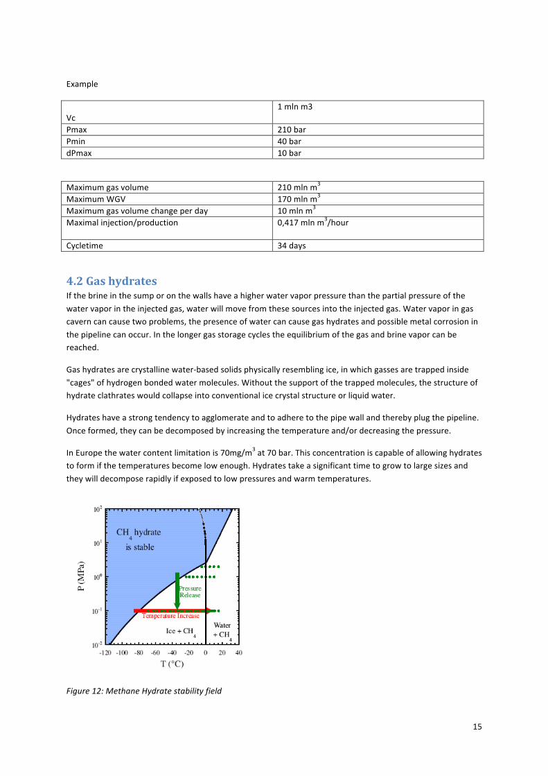
Example
Vc
1mlnm3
Pmax 210barPmin 40bardPmax 10bar
Maximumgasvolume 210mlnm3MaximumWGV 170mlnm3Maximumgasvolumechangeperday 10mlnm3Maximalinjection/production 0,417mlnm3/hour
Cycletime 34days
4.2GashydratesIfthebrineinthesumporonthewallshaveahigherwatervaporpressurethanthepartialpressureofthe
watervaporintheinjectedgas,waterwillmovefromthesesourcesintotheinjectedgas.Watervaporingascaverncancausetwoproblems,thepresenceofwatercancausegashydratesandpossiblemetalcorrosionin
thepipelinecanoccur.Inthelongergasstoragecyclestheequilibriumofthegasandbrinevaporcanbereached.
Gashydratesarecrystallinewater‐basedsolidsphysicallyresemblingice,inwhichgassesaretrappedinside
"cages"ofhydrogenbondedwatermolecules.Withoutthesupportofthetrappedmolecules,thestructureofhydrateclathrateswouldcollapseintoconventionalicecrystalstructureorliquidwater.
Hydrateshaveastrongtendencytoagglomerateandtoadheretothepipewallandtherebyplugthepipeline.
Onceformed,theycanbedecomposedbyincreasingthetemperatureand/ordecreasingthepressure.
InEuropethewatercontentlimitationis70mg/m3at70bar.Thisconcentrationiscapableofallowinghydratestoformifthetemperaturesbecomelowenough.Hydratestakeasignificanttimetogrowtolargesizesand
theywilldecomposerapidlyifexposedtolowpressuresandwarmtemperatures.
Figure12:MethaneHydratestabilityfield
16
Whenoperatingwithinasetofparameterswherehydratescouldbeformed,therearestillwaystoavoidtheirformation.
• addingchemicalscanlowerthehydrateformationtemperatureand/ordelaytheirformation
• Replacingbrinewithorganicliquids
• Sumpcoverage
• Caverndrying
Theseoperationsareconsideredenoughtoavoidformation.
TemperatureThetemperatureofrockincreaseswithdepth,atypicalvaluebeingatemperaturerateof45°Cper1000m,
butcavernsareleachedoutusingsoftwaterpumpedfromariver,lakeorshallowaquiferwhosetemperatureiscooler.Brinetemperatureattheendofleaching,isclosetothesoftwatertemperatureandsignificantly
smallerthanrocktemperature.Duringconstructionofnaturalgasstoragecavernsbysolutionmining,thetemperaturedistributioninthesurroundingsofthecavernisextensivelydisturbed.
Whenthecavernremainsinactive,afterleachingiscompleted,theinitialtemperaturedifferenceslowly
resorbswithtime,duetoheatconductionintherockmassandheatconvectioninthecavernbrine(Berest,Broaurd,Karimi‐Jafari).
Duringgaswithdrawal,theexpansionofgascausescoolinginthecavern.Thenecessaryenergyforexpansion
workissuppliedbytheheatcontentofthegasitself.Thehigherthewithdrawalrate,thelessisthetimeavailableforheattransferatthecavernwall.Therefore,thegastemperaturedecreasesmorerapidly.The
extremecaseisanadiabaticexpansionwithoutanyheattransferatthewall.
Inthiscase,thepreviouscoolingofthesaltrockbythesolutionminingprocesshasanegativeeffect.Becauseofaconsiderabledecreaseintemperature,theriskofdevelopinggashydratesincreases.Gashydratesdevelop
incaseofhighpressureandlowtemperature,aswellasinthepresenceofwater.Thegaswithdrawalratehastobereducedorwithdrawaleveninterruptedinordertoavoidpressureandtemperatureconditionswhen
hydratescandevelop.(WaldenS.)
Whentheformationofhydratesisconsidered,thepresenceofwaterasapreconditionforthisisalsorelated
tothecooledrock,butnowinapositivesense.Whilemeasuringthewatercontentinnaturalgasstoragecaverns,itwasnoticedagainandagainthattherewasarapidincreaseofwatercontentofgasinthelower
partofthecavern.Therefore,itcanbeconcludedthatthiswetgasisimmobileandthusnotinvolvedintheconvectionflowintheupperpartofthecavern.Besidelossofheatduetoevaporationatthebrinesurfacein
thecavernsump,considerablecoolingofthissectionduringsolutionminingcanbeassumedbecauseofthelongdurationofinfluenceofthecoldwater.Nevertheless,withregardtothesequestions,eachcavernshould
beregardedindividually,asconsiderablespecificdifferencesbetweencavernsmayexist.(WaldenS.)
Thetemperaturedistributioninthesurroundingsaltbodywillaffectthegastemperatureinthecavernintheshortandlongterm.Becauseoftheheatreservesintherock,thecoolingeffectofthesolutionminingprocess
willdecreaseinthecourseoftheoperationtime.Buttheinitialtemperaturegradientcanneverbereachedagain,duetoconvectionflowinthegasphaseanddisturbancescausedbygasinjectionorwithdrawal
activities.(WaldenS.)
4.3.RockmechanicsinsaltThebehaviorofcavernsandminescanonlybeunderstoodandpredictedbytakingintoaccountthecreepandotheraspectsofsalt.Butthemechanicalbehaviourofsaltisofaveryhardcomplexity,andseveralaspectsof
17
itarestillopentodiscussion.InallthearticlesIreadyouseealotofdifferentwaystodescribesaltmechanics.Iwilltrytogivesomeaspectsofmechanicalbehaviorofsalt.Undercertainloadingconditionssaltmaybecomepermeableorfailincompressionorfractureundertension.Fracturingcanresultinfluidorgaslossesfromacavernorfloodingofacavern,whenaconnectiontoan
aquiferhasbeenaccidentallyestablishedbyfracturing.
4.3.1.CreepofrocksaltRocksaltcreepisusuallyinthreestages:primary,secondaryandtertiary.Primarycreepcomponentsmaybe
negligibleforgeologicalstudies,becauseitstimescaleisverysmall.Butresearchersareindebatewhetherornotprimarycreephastobetakenintoaccountinthecaseofminingandstorageinsalt.Theshortertheperiod
ofloadingandthelowerthetemperature,themoreimportanttheprimarycreepcomponentbecomes.Temperatureisaveryimportantparametercoveringthecreepofrocksalt,sinceallmechanismsunder
considerationarethermallyactivated.(Breunese,J.Netal.)
Secondarycreeprepresentsanequilibriumstatebetweenstrainhardeningandrecoveryprocesses.Tertiarycreepisusuallyattributedtoexpansionandisthephaseofafulldisintegrationofthepolycrystalstructure.
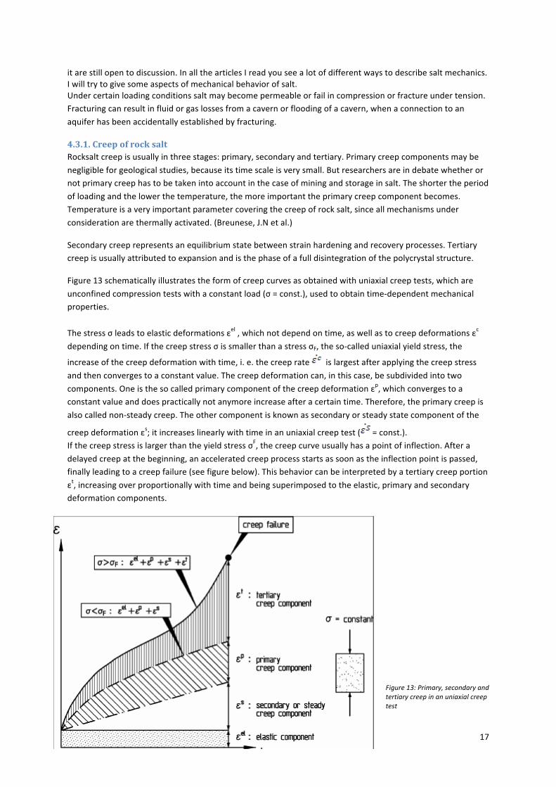
Figure13schematicallyillustratestheformofcreepcurvesasobtainedwithuniaxialcreeptests,whichare
unconfinedcompressiontestswithaconstantload(σ=const.),usedtoobtaintime‐dependentmechanicalproperties.
Thestressσleadstoelasticdeformationsεel,whichnotdependontime,aswellastocreepdeformationsεc
dependingontime.IfthecreepstressσissmallerthanastressσF,theso‐calleduniaxialyieldstress,the
increaseofthecreepdeformationwithtime,i.e.thecreeprate islargestafterapplyingthecreepstress
andthenconvergestoaconstantvalue.Thecreepdeformationcan,inthiscase,besubdividedintotwo
components.Oneisthesocalledprimarycomponentofthecreepdeformationεp,whichconvergestoaconstantvalueanddoespracticallynotanymoreincreaseafteracertaintime.Therefore,theprimarycreepis
alsocallednon‐steadycreep.Theothercomponentisknownassecondaryorsteadystatecomponentofthe
creepdeformationεs;itincreaseslinearlywithtimeinanuniaxialcreeptest( =const.).IfthecreepstressislargerthantheyieldstressσF,thecreepcurveusuallyhasapointofinflection.Aftera
delayedcreepatthebeginning,anacceleratedcreepprocessstartsassoonastheinflectionpointispassed,finallyleadingtoacreepfailure(seefigurebelow).Thisbehaviorcanbeinterpretedbyatertiarycreepportion
εt,increasingoverproportionallywithtimeandbeingsuperimposedtotheelastic,primaryandsecondarydeformationcomponents.
Figure13:Primary,secondaryandtertiarycreepinanuniaxialcreeptest

18
4.3.2.PrimarycreepPrimarycreepisdependentontemperature.Therelationbetweenstressandstrainratecanbegivenbya
powerlawfunction.ThislawiscalledthecreeplawofMenzel‐Schreiner(1972).
Thislawwithanextensionofatemperaturefunction(theArrheniusfunction):
)n
Wherevaluesβcanbecalculatedtorangebetween0.33and0.44.Wherenrangesbetween9to15.TemperatureT(K),gasconstantR(8.314J/K/mol)andactivationenergyQ(J/mol).
4.3.3.SecondarycreepAtrelativelyelevatedtemperatures(500–1000˚K)andlowstrainrates,secondarycreepstartstoplayan
importantrole.Strainiscausedbydirectedstress.Thesecondarycreeplaw(Poirier1972,Fransen1993)is:
Poiriermentionsarangeofmfrom4to7.
However,noteveryproblemrequiresthedeterminationofallparameters.Asalreadymentioned,stressessmallerthantheyieldstressonlyleadtoelasticaswellasprimaryandsecondarycreepdeformations.Insuch
cases,thestress‐strainbehaviorofthesaltrockiscompletelydescribedbytheparametersE,ν,Ep,ηp,m,aandn.Inlong‐termstudies,thesecondarycreepoftenprevails,becausethestressalterationsduetoan
opening'sexcavationand,thus,theprimarycreepdeformationsarelimitedwithrespecttotime.Insuchcases,theprimarycreepdeformationsmaybeneglectedsothatonlytheparametersE,ν,aandnarenecessaryto
describethestress‐strainbehavior.
Mainfeaturesofsteady‐statecreeparecapturedbythefollowingsimplemodel(Norton‐Hoffpowerlaw):ε ̇=A e^(((-Q)/RT) ) (1/(n+1)) (∂/∂σ) [(√3J2)n+1
WhereJ2isthesecondinvariantofthedeviatoricstresstensor;A,n,Q/Raremodelparameters.
Toslowdownthecreepeffectitisimportanttokeepthepressureclosetolithostaticandtheshearstressesclosetozero.InthecaseofEnecoGasspeicheritisnotfavourabletokeepthepressureclosetolithostatic
pressure.Toslowdownthecreepeffecttherehastobeanhealingperiod,wherethegaspressureinthecavernisclosetothelithostaticpressure.
However,thesesimpleapproximationsarepoorlysuitedforundergroundstoragecaverns,wherecaverngaspressurevariessignificantlywithtime.Theseformulaedoesnotcapturethetransienteffects,whichplayamajorroleinthiscontext.(Vouilleetal.andHugout)
4.4PermeabilitySaltsbehaveinamannersomewhereinbetweenaductilematerial(likesteel)andabrittlemanner(likehard
rock).Insufficientbondingstrengthandnonuniforminternalstressesleadtomicro‐crackswhenloadedunderthewrongconditions.
Theelasticbreakdownpressureistheoreticallymorethantwicethelithostaticpressureforanisotropicstress
fieldinelasticrock Howeverelasticbreakdownisneverreachedat
thislevel.Accordingtoalotoftheories,thestressesaroundtheboreholedropasaresultofcreep,ifthe

19
boreholepressureisforalongtimebelowthelithostaticpressure.Whentheboreholeispressuredfast,thetangentialstressesbecometensileatapressurethatisbelowtheelasticbreakdownpressure.Butacreep
relatedstressdropwillhavesomeeffectinthebreakdownpressure.
Byenteringthecrystalboundaries,fluidsnolongersupportthesalt,insteadtheydecreasethecrystalline
stressesandthesaltstrength.Anotherimportantfactorforthepermeabilityisthehydraulicfracturing.Itisasourceofcavernleakagebecauseofthefracturesitgeneratesinthesaltmass.Saltpermeabilityisstrongly
influencedbythestateofstress.Especiallystresses,liketensileorhighdeviatoricstresses,developedatthecavernwall.Theyoccurwhentheinterncavernpressureisveryhighorverysmall.Soafastpressurebuildup
willleadtoahigherbreakdownpressure,sincemicrocrackandfluidintrusiontaketime.
Sowecansaythatbyfluidintrusionsaltbehavesasifitwasapermeablematter.Themaximumfluidexcesspressureinanundergroundcavern,withrespecttotheminimuminsitustressisequaltothetensilestrength.
Therealproblemisusuallythe“piping”orcasing,thecementedwellthatconnectsthecaverntotheground
surface.Correctandstrongwelldesignspreventmostleakages,testingisnecessarytoensurethatthereisacceptabletightness.
4.5CavernspacingFordevelopingnewcavernsthestressdistributionandconcentrationaroundandbetweencavernsisimportant.Forstressevaluationitisnecessarytoknowthevirginstressofthesaltdepositandthemechanical
propertiesofthesalt.Stressdistributionaroundmultiplecavernsisverycomplicated.Thedomainofstressinteractionbetweensaltcavernsisdifficultmatter,becauseplasticitysolutionsindicatethatstressesbeyond
theyieldzonesurroundingacavernaregreaterthatwouldbepredictedbyanelasticsolution.Asafeformationofmultiplewellsisachievedbyatrigonallayoutofsinglewells.Asseeninfigre14thedistance
betweenthewellshavetobe2*diameterofthecavern+2*pillarzone+2*radiusofthecavern
figure14:Determinationofcavernwellspacing
20
4.6SubsidenceItisawell‐knownfactthatnaturalsolutionofconcealedsaltbedsbycirculatinggroundwaterleadstosubsidenceofthelandsurface.Inaddition,subsidenceandimpactsonhydrologeologicalregimesoccuratmanyundergroundminingoperations,causingchangestosurfacelandforms,groundwaterandsurfacewaterflow.Allsolution‐minedcavernsconvergeastheyverygraduallyshrinkduetosaltcreep(Bérest&Brouard,2003).Theshapeanddepthofthesubsidencebowlvaryaccordingtomanyparameters.Likecavernvolumes,depth,spacingbetweencaverns,rockpropertiesandtheproductionrateandscenario.Veryrapidsqueezefromasinglecavernisbelievedtoresultinanarrowbowlbecausesaltsqueezesoveralimitedarea.Slowsqueezefromasinglecavernresultinawidebowlbecausethesqueezeisspreadoveralargerarea.Tocontrolsubsidence,itisofgreatimportancetodesignaproperthicknessofsaltpillarabovethecavern.Thebestcontrolofcavernsubsidenceisachievedbyatrigonallayoutofsinglewells.Thecollapseofacavern
leadstodamageofthesurfaceonlyinthecaseofshallowsolutionmining.Atgreaterdepth(likeover1000meter)destructionofthegroundsurfaceisimpossible.
Severalmathematicalmodelshavebeendevelopedfortheanalysisofsubsidence.Allofthemhavesomedrawbackbecausetheydonotheldthediscontinuousnatureofrocksaltinmind.
Therehastobesomefeaturesheldinmind:
‐ Squeezevolumesarenotthesameasleachingvolumes
‐ Thedipofthesaltlayers‐ Theelasticpropertiesoftheoverburden
‐ Theoccurrenceoffaults‐ Thesaltmassisuniformlydeformed.
BecausetheEpeareaisaruralareaitisveryimportantthatsubsidenceismonitoredconstantly.Theverticalmagnitudeofthesubsidenceitselftypicallydoesnotcauseproblems.Onlyfordrainageitcauseproblems.Moredangerousistheassociatedsurfacecompressiveandtensilestrains,curvature,tiltsandhorizontal
displacement.Thesefactorscausetheworstdamagetothenaturalenvironment,buildingsandinfrastructure.
4.7StoragepressureDeterminationofthemaximumstoragepressureinthecavernisafunctionofseveralvariables:design
specifications,regionalpressureandknowntemperaturegradients.Calculationsvaryfromcompanytocompanyandsitetosite.Themostimportantfactistheoverpressuringofthecasingshoe.Hightemperature
effectsarenotthatimportant,butthelithostaticpressurecalculatedfromwelllogsisimportant.
Lithostaticpressureisapressure,equalinalldirection,causedbytheweightoftheoverlyingrocks.Lithostaticpressureindicesastressinrocks.Whentheelasticlimitoftherockisreached,itwillchangeshapeinnon‐
reversiblefashion.Thelithostaticpressureatdepthzisgivenbytheformulabelow.Whereρ(z)isthedensityoftheoverlyingrockandgistheaccelerationduetogravity.Andp0isthedatumpressure,thepressureatthe
surface.IntheattachmentyoufindthecalculationofthepressureinthetwoEnecowells.
Temperatureaffectstheminimumstoragepressurebecausethehigherthetemperature,themorelikelycreepandclosurewilloccur.Highertemperaturealsoaffectsthemaximumallowablediameterofthecavern.Itismoredifficulttocalculatetheminimumpressureforinhomogeneoussalt.Maximumsafeoperatingpressuresforareservoirdependonfourprimaryfactors:
•Themechanicalpropertiesofthereservoirandoverburden
•Theinsitustressesandfracturepressureinthereservoir
21
•Stressesinducedinthereservoirbygascycling;and,•Stressesinducedinthecaprockmaterialbygascycling
FromSMRIresearchworkonthedeterminationofthemaximuminternalcavernpressureforgasstoragecavernsitisknownfurther,thattheshapeofthecavern’sroofhasamajorinfluence.
Tohavesafegasstoragethemaximumallowableoperatingpressure(MAOP)isapercentageofthecalculated
rockpressure.
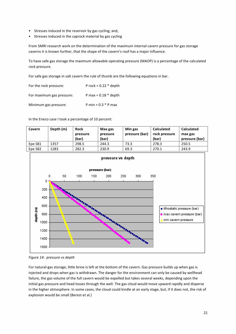
Forsafegasstorageinsaltcaverntheruleofthumbarethefollowingequationsinbar.
Fortherockpressure: Prock=0.22*depth
Formaximumgaspressure: Pmax=0.18*depth
Minimumgaspressure: Pmin=0.3*Pmax
IntheEnecocaseItookapercentageof10percent:Cavern Depth(m) Rock
pressure(bar)
Maxgaspressure(bar)
Mingaspressure(bar)
Calculatedrockpressure(bar)
Calculatedmaxgaspressure(bar)
EpeS81 1357 298.5 244.3 73.3 278.3 250.5EpeS82 1283 282.3 230.9 69.3 270.1 243.9
Figure14:pressurevsdepthFornatural‐gasstorage,littlebrineisleftatthebottomofthecavern.Gaspressurebuildsupwhengasis
injectedanddropswhengasiswithdrawn.Thedangerfortheenvironmentcanonlybecausedbywellheadfailure,thegasvolumeofthefullcavernwouldbeexpelledbuttakesseveralweeks,dependinguponthe
initialgaspressureandheadlossesthroughthewell.Thegascloudwouldmoveupwardrapidlyanddisperseinthehigheratmosphere.Insomecases,thecloudcouldkindleatanearlystage,but,ifitdoesnot,theriskof
explosionwouldbesmall(Berestetal.)
22
4.8CavernsabandonmentWhenthecavernswillnotbeusedanymore,thecavernwillusuallybefilledwithbrine.Thisismaybethecase
fortheEnecocavernsin2030.Cementwillbepouredinthewellandcasing.Afterthecavernissealed,thebrinepressurewillbuildup.Thefinalvalueofcavernbrinepressureisthemostimportant.
Assaltcreepstowardacavern,thecavernbrineisforcedinasmallerroom,anditspressurebuildsupinasealedcavern.Aftersometime,theprocessbecomesslowerasthecavernpressurebecomeshigher,ultimatelystoppingwhenthecavernpressureisequaltogeostatic(Pi=P¥),afterseveralcenturies(Wallnerand
Paar,1997)
TheauthorsBérestandBrouard,fearthatbrinepressureeventuallyreachafigurelargerthanthegeostaticor
lithostaticpressure,leadingtohydrofracturing.Whichcanleadtoupwardbrineflowthroughfracturesandpollutingdrinkablewater.Themainfactorsofbrinepressurebuilduparecaverncompressibility,saltmass
creep,saltpermeability,leaksandbrinethermalexpansion.

23
5 Conclusionsandrecommendations:
Thegeotechnicaldesignofgasstoragecaverninrocksaltisacomplextask.Astherearenogeneralaccepteddesigncriteriaavailable,alotofdifferentdesignmethodsdoexistallovertheworld.Itisageneral
understandingthatthedemandsofstaticstabilityandtightnessaswellaspublicsafetyatthesurfacemustbeguaranteedbythedesignandtheoperationofthesegeotechnicalconstructions.
Stressfieldscausedbythepresenceofacavernresultincreepatanyshearstressandanyinsitutemperature.
Cavernvolumereductionwithtimeaccompaniedbysurfacesubsidenceisanimportantconsequence.Bykeepingthepressureclosetolithostaticandtheshearstressesclosetozero,theeffectofthoseareslowed
down.Becauseitisnotfavorabletherehastobeahealingperiodeverywhile.
Inthecourseofsolutionminingoperationsforconstructinganaturalgasstoragecavern,aconsiderable
amountofthermalenergyiswithdrawnfromthesaltrock.Thereasonliesintheuseofacoldleachingfluidandtheconsumptionofenergyinthedissolutionofsalt.Duringgaswithdrawal,thegascoolsdowndueto
expansion.Thiscoolingeffectispartlycompensatedbyheatsupplyfromtherock.Themoretherockisalreadycooledbythesolutionminingprocess,thelessfavourablearetheconditionswithregardtogas
withdrawal.Theseconditionshavetobeheldinmindwithregardtoformationofgashydrates.
Theproblemofwaterevaporationfromthecavernsumpintothestoredgashassofarnotbeensolved.ThatiswhytheEnecofacilitymustbeequippedwithgasdryingsystem.Ifthegascontainstoomuchwaterthereisa
possibilityforformationofgashydrates.
Gashydrates: • Avoidoperationalconditionsthatmightcauseformationofhydratessuchaspressureand
temperature
• Temporarilychangeoperatingconditionsinordertoavoidhydrateformation;
• Preventformationofhydratesbyadditionofchemicalsorinhibitors
Thepositionofthecavernisimportantforthestabilityofthecavern.Therearemanyparametersthatplayimportantroles,includingroofshape,distancetothetopofthesaltformation,spacingbetweentwoadjacent
caverns,anddistancefromthedomeflanks.
Abandonmentofthecavernshastobestudiedmoreclosely,especiallythehydrofracturingfearedbytheauthorsBérestandBrouardandWallnerandPaar.
Cyclesandstorageparameterscanbeeasilycalculatedbysoftwarespeciallydesignedforundergroundgasstoragefacilities.LikeSaltCavernGasStorageToolboxbyGasTechnologyInstitute,PipelineResearchCouncilInternationalandTechnicalToolboxesitcontainsamathematicalsimulatortocreatealternativedetaileddesignsimulationscalculatingtransientwellheadpressuresandtemperatures,feasibilitycalculationsformeetingpotentialgasnominations,hydrateformationrestrictionsetcIrecommendEnecotopurchasethissoftwaretooltounderstandanduseitfortheirgasstorageproject.Forfurtherquestionsorrecommendationstheauthorwillbegrateful.
24
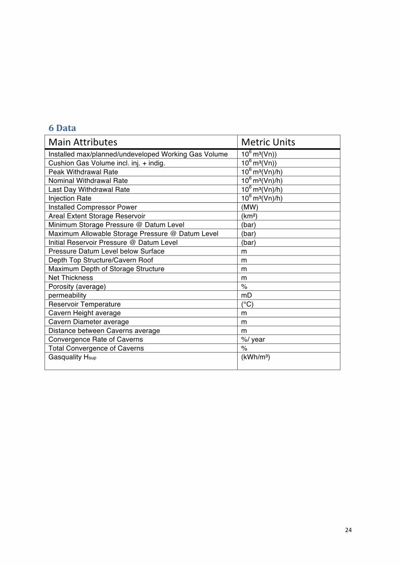
6Data
MainAttributes MetricUnitsInstalled max/planned/undeveloped Working Gas Volume 106 m³(Vn))Cushion Gas Volume incl. inj. + indig. 106 m³(Vn))Peak Withdrawal Rate 106 m³(Vn)/h)Nominal Withdrawal Rate 106 m³(Vn)/h)Last Day Withdrawal Rate 106 m³(Vn)/h)Injection Rate 106 m³(Vn)/h)Installed Compressor Power (MW)Areal Extent Storage Reservoir (km²) Minimum Storage Pressure @ Datum Level (bar) Maximum Allowable Storage Pressure @ Datum Level (bar) Initial Reservoir Pressure @ Datum Level (bar) Pressure Datum Level below Surface m Depth Top Structure/Cavern Roof m Maximum Depth of Storage Structure m Net Thickness m Porosity (average) % permeability mD Reservoir Temperature (°C) Cavern Height average m Cavern Diameter average m Distance between Caverns average m Convergence Rate of Caverns %/ year Total Convergence of Caverns % Gasquality Hsup (kWh/m³)

25
7References‐ MessberichtSolvay‐ GeologischeD.Albes,15apr2003,GeologischerBerichtzurKavernenbohrungEpeS81,Dipl.
‐ GeologischeD.Albes,15apr2003,GeologischerBerichtzurKavernenbohrungEpeS82,Dipl.‐ Abschluβbericht,febr.2003,SGWEpeS81
‐ Abschluβbericht,jan.2003,SGWEpeS82‐ Lux,Karl‐Heinz(1984),GebirgsmechanischerEntwurfundFelderfahrungimSalzkavernenbau“Ein
BeitragzurEntwickulungvonPrognosemodellenfurdenHohlraumbauimduktilenSalzgebirge”,Enke.
‐ J.A.IstvanandC.W.Querio,1983,StorageofNaturalGasinSaltCaverns.‐ M.L.Jeremic,1994,Rockmechanicsinsaltmining,A.A.Balkema
‐ RichardE.Goodman,Introductiontorockmechanics,2ndeditionJohnWiley&sons‐ P.A.Fokker,Thebehaviorofsaltandsaltcaverns,Thesis,1995
‐ Kurstedt,A.(2007):SalzbergwerkEpe–VonderSolegewinnungzumgrößtenKavernenspeicherEuropas.Bergbau9/2007;Essen.
‐ Th.E.Wong,D.A.J.Batjes&J.deJager,GeologyoftheNetherlands,RoyalNetherlandsAcademyofArtsandSciences,2007.
‐ HowardL.Hartman,SeeleyW.Mudd,SMEMiningEngineeringHandbook,SME,1992
‐ Von Sedacek R.,Untertage-Gasspeicherung in Deutschland, ‐ Breunese,J.N.,vanEijs,R.M.H.E.,deMeer,S.,Kroon,I.C.,Observationandpredictionoftherelation
betweensaltcreepandlandsubsidenceinsolutionmining.TheBarradeelcase.NetherlandsInstitute
ofAppliesGeoscienseTNO,Fall2003conference5‐8October,Chester,UnitedKingdom‐ Hoelen,Q.,vanPijkeren,G.,Teuben,B.,Steenbergen,B.,Breuning,P.,gasstorageinsaltcaverns
“aardgasbufferZuidwending”TheNetherlands,23rdWorldGasConference,Amsterdam2006‐ Berest,P.,Brouard,B.,Safetyofsaltcavernsusedforundergroundstorage
‐ Bishop,WilliamM.,Areexamninationofgashydratesandnaturalgaswatercontentandtheiraffectoncavernoperations,2004
‐ ZieglerK.,GerstädtP.,HilscherA.,SafetyConceptforanLPGUndergroundStorageinGermany,2002‐ RiekenbergR.,HartmannU.,StaudtmeisterK.,Zander‐SchiebenhöferD.,Recommendation of
maximum cavern pressures for the gas storage caverns at Huntorf on the basis of three- dimensional numerical models, 2004
‐ Allen Marr W., Feasibility Study For the storage of cold compressed natural Gas in underground solution mined bedded salt caverns, 2006
‐ Brouard B., Bérest P.,Karimi-Jafari M., Thermal Effects in Salt Caverns, 2007 ‐ Berger, H., Zündel, F., Walden, S., Water in Gas Storage Caverns – Problems and Solutions, 2002 ‐ Sloan, E.D., Clathrate Hydrates of Natural Gases, 1990 ‐ Brouard B., Bérest P.,Karimi-Jafari M., Subsidence, Sinkholes and Craters above Salt Caverns, 2008

26
‐ http//www.eia.doe.gov/pub/oil_gas/natural_gas/data_publications/natural_gas_monthly/historical/
2002/2002_05/pdf/nym_all.pdf‐ www.UGSnet.de‐ http://gisos.ensg.inpl-
nancy.fr/UserFiles/File/PM_2005/PM05_pdf/T4_T6/Berest_1%20et%20al.pdf‐ Creep:http://www.geofoon.nl/nr12art2.pdf‐ http://www.brouard-consulting.com/articles/nancy-post-mining.pdfdeepsaltcaverns
abandonment‐ http://www.cadlm.fr/%5Cworkshop%5Cdoc%5Cproceedings/BerestBBDG.pdf‐ http://www.saimm.co.za/events/0309isrm/downloads/0301‐Erichsen.pdf‐ www.tno.nl
‐ http://cdl.niedersachsen.de/blob/images/C51249629_L20.pdf‐ http://www.saltinstitute.org/symposia/symposium6/haddenhorst.pdf‐ http://www.igu.org/html/wgc2006/WOC2database/index.htm
‐ http://www.rwe.com/generator.aspx/produkte/storage‐fee‐computer/epe/language=en/id=227662/page.html
‐ http://www.saltinstitute.org/symposia/symposium6/istvan.pdf
‐ http://www.gie.eu.com/index.html‐ http://www.eia.doe.gov/emeu/cabs/Germany/NaturalGas.html
27
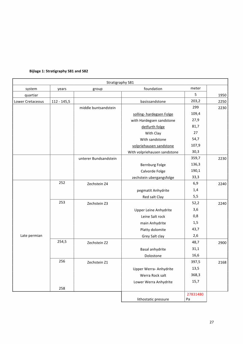
Bijlage1:StratigraphyS81andS82
StratigraphyS81
system years group foundation meter
quartiar 5 1950
LowerCretaceous 112‐145,5 basissandstone 203,2 2250
middlebuntsandstein 299 2230
solling‐hardegsenFolge 109,4
withHardegsensandstone 27,9
detfurthfolge 81,7
WithClay 27
Withsandstone 54,7
volpriehausensandstone 107,9
Withvolpriehausensandstone 30,3
untererBundsandstein 359,7 2230
BernburgFolge 136,3
CalvordeFolge 190,1
zechsteinubergangsfolge 33,3
ZechsteinZ4 6,9 2240
pegmatitAnhydrite 1,4
252
RedsaltClay 5,5
ZechsteinZ3 52,2 2240
UpperLeineAnhydrite 3,6
LeineSaltrock 0,8
mainAnhydrite 1,5
Plattydolomite 43,7
253
GreySaltclay 2,6
ZechsteinZ2 48,7 2900
Basalanhydrite 31,1
254,5
Dolostone 16,6
ZechsteinZ1 397,5 2168256
UpperWerra‐Anhydrite 13,5
WerraRocksalt 368,3
LowerWerraAnhydrite 15,7
Latepermian
258
lithostaticpressure27831480Pa

28
StratigraphyS82
system years group foundation meter density
quartiar 5 1950
LowerCretaceous 112‐145,5 basissandstone 215,8 2250
middlebuntsandstein 311,9 2230
solling‐hardegsenFolge 109,2
withHardegsensandstone 27,6
detfurthfolge 83,6
WithClay 27,1
Withsandstone 56,5
volpriehausensandstone 119,1
Withvolpriehausensandstone 24,6
lowerBundsandstein 384,5 2230
BernburgFolge 153,7
CalvordeFolge 201,6
zechsteinubergangsfolge 29,2
ZechsteinZ4 5,9 2900
pegmatitAnhydrite 1,6
252
RedsaltClay 4,3
ZechsteinZ3 41,1 2240
UpperLeineAnhydrite 3,9
LeineSaltrock 1,2 2185
mainAnhydrite 0,8 2168 Plattydolomite 33,5
253
GreySaltclay 1,7
ZechsteinZ2 49,4 2240
anhydrite 24,6 2900
stassfurtsalt 3,8 2240
Basalanhydrite 24,6
254,5
Dolostone 11,3
ZechsteinZ1 324,4 2168256
UpperWerra‐Anhydrite 14,9
WerraRocksalt 296,3 2168
LowerWerraAnhydrite 13,2
Latepermian
258
BreuneseJ.Netal. lithostaticpressure 27013161Pa
29
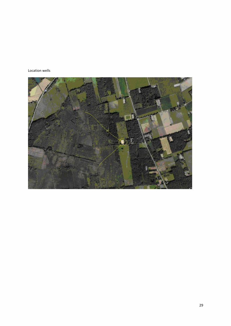
Locationwells
Related Documents