www.ijcrt.org © 2021 IJCRT | Volume 9, Issue 7 July 2021 | ISSN: 2320-2882 IJCRT2107535 International Journal of Creative Research Thoughts (IJCRT) www.ijcrt.org f55 UNDERGROUND CABLE FAULT DETECTION USING ARDUINO 1 Lata Rai, 2 Neha Chikane, 3 Rachna Karale, 4 Dhananjay Sarfare, 5 Prof. Sanket Singhania 1 Student, 2 Student, 3 Student, 4 Student, 5 Associate Professor 1 Electronics & Telecommunication Engineering Department, 1 Shivajirao S. Jondhale College Of Engineering, Dombivli (E), India Abstract: In urban areas, electrical cables run underground instead of running over, because it does not affected by any adverse effect of weather such as heavy rainfall, snow, thunder storm. Whenever a fault occurs within the underground cable, it is difficult to detect the exact location of the fault for the repair process of particular cable. The proposed system found the point of the exact location of fault. The paper uses the standard concept of Ohm’s law i.e. when a low dc voltage is applied at the end of feeder through series resister (cable lines) then the current will vary depending on the location of the fault Short in the cable. This system uses an Arduino microcontroller and a rectified power supply. In this case, the current detection circuit in combination with the resister is connected to the microcontroller with the aid of an ADC device to represent the length of wire in Km. Error creation is performed by a set of switches. The relays are controlled by a relay exciter IC, which is used to check cable line. A 16x2 LCD is used to display information. Also one more feature is that using GSM the message of fault detection, location of fault and distance of fault from base station in kilometres this all information is send to base station. As soon as a fault occurs in a cable the buzzer produce the alarm to alert and to take an immediate action by field workers.[1] Key Words — Arduino microcontroller, Ohm’s law, LCD, GSM, ADC, Cable Fault,GPS Module Index Terms Introduction: In this project we proposed a fault localization model for the underground cable lines with Arduino. The purpose of this paper is to determine the distance from the base station's underground cable fault in kilometres. In this project we used a simple concept of ohm’s low. When a fault occurs in the system the distance located on liquid crystal display (LCD). Until the last decade, cables were designed to be placed above the head and, at present, there is no underground cable that is higher than the previous method. adverse weather conditions such as storms, snow, torrential rains and pollution does not effect on underground lines But when a fault occurs in underground lines it is difficult to locate the fault in underground cable. We will find the exact location of the fault. Now the world has become digitized so, the project is to detect exact location of the fault in digital form. Underground cabling system is a more common practice in many urban areas. Although the fault occurs for some reason, at that time, the repair process for this particular cable is difficult because of not knowing the exact location of the cable breakdown. Fault in cable can be classified in two groups: Open circuit fault:-In open circuit fault there is no current because there no conducting complete loop for current flowing that is I=0 in this fault supply voltage is equal to the output voltage. Open circuit fault is better than short circuit fault. Short circuit fault:- In this fault output voltage is zero but current is same Further short circuit fault can be categorized in two types: Symmetrical fault:- In this fault :equal lead current and equal phase shift. Unsymmetrical fault: - In this fault magnitude of current is not equal & phase shifting is not equal by 120 degree. Terminal method:- in this method used to detect the fault location in underground

Welcome message from author
This document is posted to help you gain knowledge. Please leave a comment to let me know what you think about it! Share it to your friends and learn new things together.
Transcript
www.ijcrt.org © 2021 IJCRT | Volume 9, Issue 7 July 2021 | ISSN: 2320-2882
IJCRT2107535 International Journal of Creative Research Thoughts (IJCRT) www.ijcrt.org f55
UNDERGROUND CABLE FAULT DETECTION
USING ARDUINO
1Lata Rai, 2Neha Chikane, 3Rachna Karale, 4Dhananjay Sarfare, 5Prof. Sanket Singhania
1Student, 2Student, 3Student, 4Student, 5Associate Professor
1Electronics & Telecommunication Engineering Department, 1Shivajirao S. Jondhale College Of Engineering, Dombivli (E), India
Abstract: In urban areas, electrical cables run underground instead of running over, because it does not
affected by any adverse effect of weather such as heavy rainfall, snow, thunder storm. Whenever a fault
occurs within the underground cable, it is difficult to detect the exact location of the fault for the repair
process of particular cable. The proposed system found the point of the exact location of fault. The paper
uses the standard concept of Ohm’s law i.e. when a low dc voltage is applied at the end of feeder through
series resister (cable lines) then the current will vary depending on the location of the fault Short in the
cable.
This system uses an Arduino microcontroller and a rectified power supply. In this case, the current detection
circuit in combination with the resister is connected to the microcontroller with the aid of an ADC device to
represent the length of wire in Km. Error creation is performed by a set of switches. The relays are controlled
by a relay exciter IC, which is used to check cable line. A 16x2 LCD is used to display information. Also one
more feature is that using GSM the message of fault detection, location of fault and distance of fault from
base station in kilometres this all information is send to base station. As soon as a fault occurs in a cable the
buzzer produce the alarm to alert and to take an immediate action by field workers.[1]
Key Words — Arduino microcontroller, Ohm’s law, LCD, GSM, ADC, Cable Fault,GPS Module
Index Terms
Introduction:
In this project we proposed a fault localization model for the underground cable lines with Arduino.
The purpose of this paper is to determine the distance from the base station's underground cable fault in
kilometres. In this project we used a simple concept of ohm’s low. When a fault occurs in the system the
distance located on liquid crystal display (LCD). Until the last decade, cables were designed to be placed
above the head and, at present, there is no underground cable that is higher than the previous method. adverse
weather conditions such as storms, snow, torrential rains and pollution does not effect on underground lines
But when a fault occurs in underground lines it is difficult to locate the fault in underground cable. We will
find the exact location of the fault. Now the world has become digitized so, the project is to detect exact
location of the fault in digital form. Underground cabling system is a more common practice in many urban
areas. Although the fault occurs for some reason, at that time, the repair process for this particular cable is
difficult because of not knowing the exact location of the cable breakdown. Fault in cable can be classified in
two groups: Open circuit fault:-In open circuit fault there is no current because there no conducting complete
loop for current flowing that is I=0 in this fault supply voltage is equal to the output voltage. Open circuit
fault is better than short circuit fault. Short circuit fault:- In this fault output voltage is zero but current is same
Further short circuit fault can be categorized in two types: Symmetrical fault:- In this fault :equal lead current
and equal phase shift. Unsymmetrical fault: - In this fault magnitude of current is not equal & phase shifting
is not equal by 120 degree. Terminal method:- in this method used to detect the fault location in underground
www.ijcrt.org © 2021 IJCRT | Volume 9, Issue 7 July 2021 | ISSN: 2320-2882
IJCRT2107535 International Journal of Creative Research Thoughts (IJCRT) www.ijcrt.org f56
lines without any effort This method used to locate the type of circuit occurs; the voltage drop varies with the
default length on the cable, as the current varies. A plurality of resistors is used to represent the cable and a
DC voltage is supplied at one end and the defect is detected by detecting the voltage variation the defect area
to accelerate the tracking of the buried cable. [2]
Methodology:
Advanced Methods like Fault Detection, Fault Diagnosis have Become Important for Many
Technical processes for the Improvement of Reliability, Safety and Efficiency. There are Two Types of
Fault location Methods namely Online and Offline methods. [3]
1) Online Method:-To determine the fault points this method utilizes & processes the sampled voltages &
current. Online method for underground cable is less than overhead lines.
2) Offline Method:-This method uses special instrument to test out Service of cable in the field. The offline
Methods are as follows,
Tracer Method:-In this Method Fault Point in the Cable lines is detected by walking on Ground. The Fault
point is indicated from Audible signal or Electromagnetic signal. It is used to Point out Fault location Very
Accurately.
Example:-A] Tracing Current Method
B] Sheath Coil Method
Terminal method:-This Technique is used to Detect Fault Location of Cable from one or both ends without
Tracing. The General Area of Fault is located by the use of this Method, to Expedite tracing on buried cable.
Example:-A] Murray Loop Method
B] Impulse Current Method
Literature Survey: 2.1 Presented Design & Implementation of Fault Identification in Underground Cables Using IOT.
This project is to determine the distance of underground cable fault from the base station in
kilometres and displayed over the internet. Underground cable system is a common followed in major areas
in Metro cities. While a fault occurs for some reason, at that time the fixing process related to that particular
cable is difficult due to exact unknown location of the fault in the cable. This Technology is used to find out
the exact location of the fault and to send data in graphical format to our website using a GSM module at
the same time it display on the LCD screen.
The project uses the standard theory of Ohms law, i.e., when a low DC voltage is applied at the feeder
end through a series resistor (Cable lines), then the current would vary depending upon the location of the
fault in the cable as the resistance is proportional to the distance. In case there is a short circuit (Line to
Ground), the voltage across series resistors changes according to the resistance that changes with distance
.This is then fed to an ADC to develop precise digital data which the programmed microcontroller of the 8051
family displays in kilometres.[4]
2.2 Presented Analysis of Underground Cable Fault Distance Locator.
Underground cables are prone to a wide variety of faults due to underground conditions, wear and
tear, rodents etc. Also detecting fault source is difficult and entire line is to be dug in order to check entire
line and fix faults. So here we propose cable fault detection over IOT that detects the exact fault position over
IOT that makes repairing work very easy. The repairmen know exactly which part has fault and only that area
is to be dug to detect the fault source. This saves a lot of time, money and efforts and also allows to service
underground cables faster. We use IOT technology that updates the monitored fault information to internet.
The system detects fault with the help of potential divider network laid across the cable. Whenever a
fault gets created at a point shorting two lines together, a specific voltage gets generated as per the resistors
network combination. This voltage is sensed by the microcontroller and is updated to the user. The information
conveyed to the user is the information regarding faults detection. The microcontroller retrieves the fault line
data and displays over LCD display, also it transfers this data over internet to display on Gmail server. [5]
www.ijcrt.org © 2021 IJCRT | Volume 9, Issue 7 July 2021 | ISSN: 2320-2882
IJCRT2107535 International Journal of Creative Research Thoughts (IJCRT) www.ijcrt.org f57
2.3 Arduino Based Underground Transmission Cable Fault Location System.
The transmission line fault location requires intense human effort and resources. Typically this process
is time consuming and while digging the cable there is a risk of damaging the insulation .This paper provides
a simple and safe alternative by automating the process of fault detection and location. The project uses the
simple concept of OHMs law where a low DC voltage is applied at the feeder end through a series resistor.
The current would vary depending upon the length of fault of the cable in case there is a short circuit
of LL or 3L or LG etc. The series resistor voltage droop changes accordingly which detects the exact location
of the fault for process of repairing that particular cable. The proposed system finds the exact location of the
fault. This system uses an Arduino micro controller kit and a rectified power supply. Here the current sensing
circuits made with a combination of resistors are interfaced to Arduino micro controller kit to help of the
internal ADC device for providing digital data to the microcontroller representing the cable length in
kilometres.
The fault creation is made by the set of switches. The relays are controlled by the relay driver. A 16x2
LCD display connected to the microcontroller to display the information. In case of short circuit, the voltage
across series resistors changes accordingly, which is then fed to an ADC to develop precise digital data to a
programmed Arduino micro controller kit that further displays exact fault location from base station in
kilometres. The project in future can be implemented by using capacitor in an AC circuit to measure the
impedance which can even locate the open circuited cable. [2]
2.4 Presented Underground Cable Fault Detector Using GSM.
The main aim of the project is to detect and locate the fault in underground cable. In the urban areas,
the electrical cable runs in undergrounds instead of overhead lines. Whenever the fault occur the repairing
process becomes difficult. It is very difficult to identify the exact location of the fault in underground power
cable line. This project will ensure a shorter response time for technical crew to rectify these faults. Fault
occur due to short circuit fault, low voltage fault, high voltage fault. Previously proposed technique is used to
identify short circuit fault only.
This project is used to detect not only detect short circuit fault but also detect, low voltage fault, high
voltage fault. The system developed here works on the basis of Ohm’s law. The proposed technique is used
not only for identification but also it is used to send the detail information about the fault to the authority using
GSM and also it cut the power supply on that particular location for the security of the people .It also used to
display the type of the fault in LCD display. Whenever a fault occurs in a cable the buzzer produces the sound
to alert and to take an immediate action. [6]
2.5 Underground Cable Fault Detection using Raspberry Pi and Arduino.
This paper proposes fault location model for underground power cable using raspberry pi and the
Internet of Things which is based on the internet, which means the information will be transferred through the
internet access. The aim of this method is to determine the distance of underground cable fault from base
station in kilometres and also find the location of that faulty place. This paper uses the simple concept of
Current Transformer Theory (CT Theory). When any fault like short circuit occurs, voltage drop will vary
depending on the length of fault in cable; since the current varies Current Transformer is used to calculate the
varying current. The signal conditioner manipulates the change in voltage and a microcontroller is used to
make the necessary calculations so that the fault distance is displayed by IOT devices. These fault details are
after sent to any access point through the internet and displayed. [7]
Proposed System: Underground cable fault detector deals with finding of exact fault location from the base station
itself. The proposed system finds the exact location of the fault. This paper uses the standard concept of Ohm’s
law i.e. As soon as a low DC voltage is applied at the feeder end through a series resister, the current would
vary depending upon the location of fault in the cable. Cables have some resistance. We are mainly focusing
on the resistance. Resistance can vary with respect to the length of the cable. If the length of the cable is
increase, the value of the resistance will also increase. If any deviation occurs in the value of resistance, we
will call that is fault point and finding that place through Arduino technology. The standard of distance
(kilometre) from the base station is represented by the fault point. This value displayed by display unit LCD.
Also one more feature is that using GSM the message of fault detection, location of fault and distance of fault
from base station in kilometres this all information is send to base station. Whenever a fault occurs in a cable
the buzzer produces the alarm to alert and to take an immediate action by field workers.
www.ijcrt.org © 2021 IJCRT | Volume 9, Issue 7 July 2021 | ISSN: 2320-2882
IJCRT2107535 International Journal of Creative Research Thoughts (IJCRT) www.ijcrt.org f58
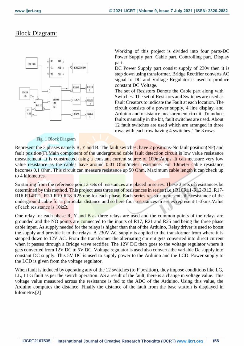
Block Diagram:
Working of this project is divided into four parts-DC
Power Supply part, Cable part, Controlling part, Display
part.
DC Power Supply part consist supply of 230v then it is
step down using transformer, Bridge Rectifier converts AC
signal to DC and Voltage Regulator is used to produce
constant DC Voltage.
The set of Resistors Denote the Cable part along with
Switches. The set of Resistors and Switches are used as
Fault Creators to indicate the Fault at each location. The
circuit consists of a power supply, 4 line display, and
Arduino and resistance measurement circuit. To induce
faults manually in the kit, fault switches are used. About
12 fault switches are used which are arranged in three
rows with each row having 4 switches. The 3 rows
Fig. 1 Block Diagram
Represent the 3 phases namely R, Y and B. The fault switches: have 2 positions-No fault position(NF) and
fault position(F).Main component of the underground cable fault detection circuit is low value resistance
measurement. It is constructed using a constant current source of 100mAmps. It can measure very low
value resistance as the cables have around 0.01 Ohm/meter resistance. For 10meter cable resistance
becomes 0.1 Ohm. This circuit can measure resistance up 50 Ohm, Maximum cable length it can check up
to 4 kilometres.
So starting from the reference point 3 sets of resistances are placed in series. These 3 sets of resistances be
determined by this method. This project uses three set of resistances in series (i.e.) R10R11-R12-R12, R17-
R16-R14R21, R20-R19-R18-R25 one for each phase. Each series resistor represents the resistance of the
underground cable for a particular distance and so here four resistances in series represent 1-3kms.Value
of each resistance is 10kΩ.
One relay for each phase R, Y and B as three relays are used and the common points of the relays are
grounded and the NO points are connected to the inputs of R17, R21 and R25 and being the three phase
cable input. As supply needed for the relays is higher than that of the Arduino, Relay driver is used to boost
the supply and provide it to the relays. A 230V AC supply is applied to the transformer from where it is
stepped down to 12V AC. From the transformer the alternating current gets converted into direct current
when it passes through a Bridge wave rectifier. The 12V DC then goes to the voltage regulator where it
gets converted from 12V DC to 5V DC. Voltage regulator is used also converts the variable Dc supply into
constant DC supply. This 5V DC is used to supply power to the Arduino and the LCD. Power supply to
the LCD is given from the voltage regulator.
When fault is induced by operating any of the 12 switches (to F position), they impose conditions like LG,
LL, LLG fault as per the switch operation. AS a result of the fault, there is a change in voltage value. This
voltage value measured across the resistance is fed to the ADC of the Arduino. Using this value, the
Arduino computes the distance. Finally the distance of the fault from the base station is displayed in
kilometre.[2]

www.ijcrt.org © 2021 IJCRT | Volume 9, Issue 7 July 2021 | ISSN: 2320-2882
IJCRT2107535 International Journal of Creative Research Thoughts (IJCRT) www.ijcrt.org f59
Hardware Requirements:
1. Arduino UNO:-It is a Microcontroller Board built using based on AT mega 328 IC. Its Operating
Voltage is 5V with Clock speed of 16MHz. Some of its Digital pins have Specialized Functions. For
example, Pin0 (RX) and Pin1 (TX) serve as Serial Port Communication for Receiving and
Transmitting Serial data. Pins 10 to 13 support SPI Communication. These Ports can be utilized for
interfacing GSM & GPS Module.
Fig. 2 Arduino Uno
2. GSM Module:-GSM Sim800L is used in this Project. It is a Quad-Band Module works with the
Frequency 850MHz and supports GPRS Coding schemes CS-1, CS-2, CS-3 and CS-4. Operating
Voltage of this Module ranges from 3.4V-4.4V and the Typical Power Consumption in Sleep
mode is 0.7mA which results in power saving. It has a SIM Interface Compatible with 3V and
1.8V SIM cards. It supports MT, MO, CB, Text and PDU Mode for SMS. It’s Serial Port Baud
Rate Ranges from 1200bps to 115200bps which is Compatible with Arduino UNO.
(a) (b) Fig. 3 GSM Module
3. GPS Module:-GPSNEO-6MV2 is the Module Used in this Project. The Operating Voltage ranges
from 2.3V to 3.6V. Its RX and TX are connected to corresponding Serial Port pins in Arduino. NEMA
is the Protocol used to read Latitude and Longitude Data.
www.ijcrt.org © 2021 IJCRT | Volume 9, Issue 7 July 2021 | ISSN: 2320-2882
IJCRT2107535 International Journal of Creative Research Thoughts (IJCRT) www.ijcrt.org f60
Fig. 4 GPS Module
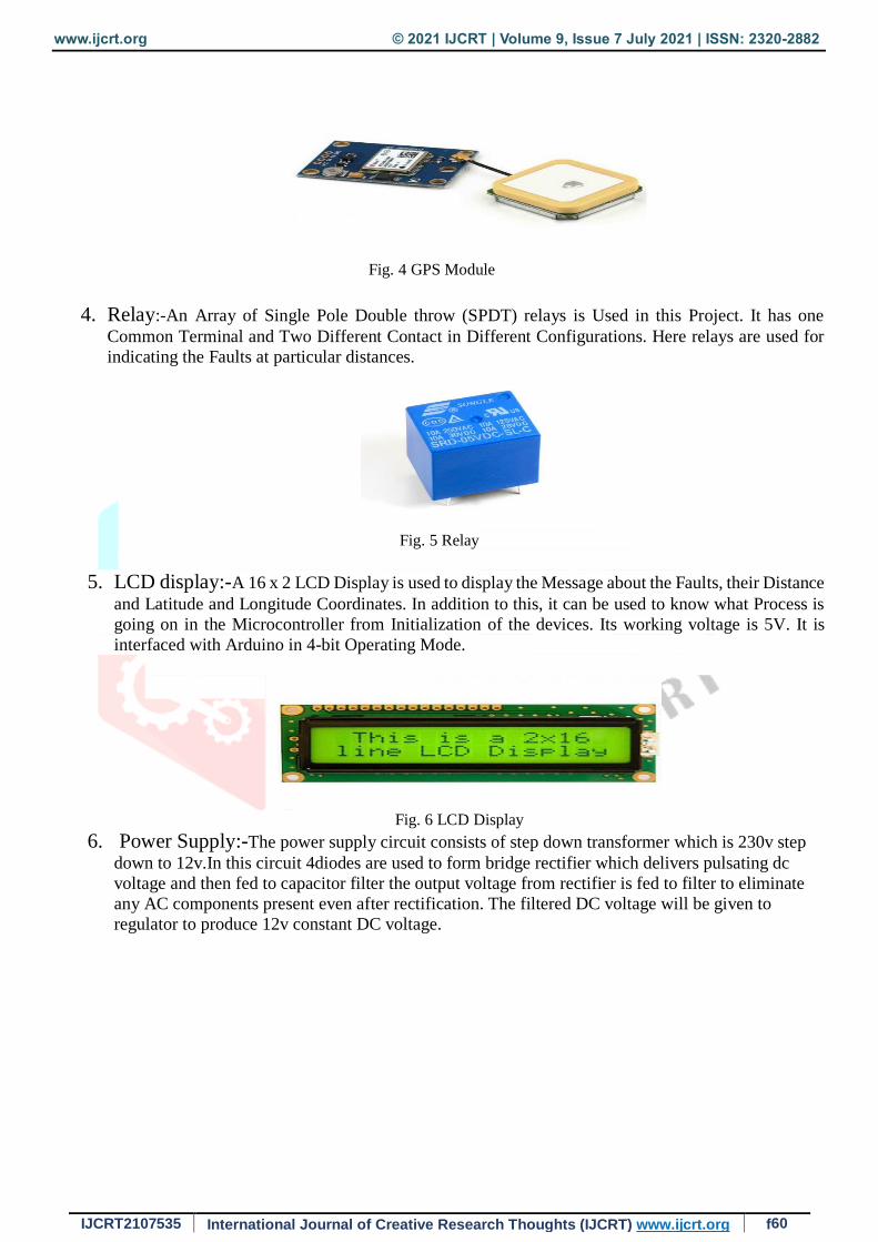
4. Relay:-An Array of Single Pole Double throw (SPDT) relays is Used in this Project. It has one
Common Terminal and Two Different Contact in Different Configurations. Here relays are used for
indicating the Faults at particular distances.
Fig. 5 Relay
5. LCD display:-A 16 x 2 LCD Display is used to display the Message about the Faults, their Distance
and Latitude and Longitude Coordinates. In addition to this, it can be used to know what Process is
going on in the Microcontroller from Initialization of the devices. Its working voltage is 5V. It is
interfaced with Arduino in 4-bit Operating Mode.
Fig. 6 LCD Display 6. Power Supply:-The power supply circuit consists of step down transformer which is 230v step
down to 12v.In this circuit 4diodes are used to form bridge rectifier which delivers pulsating dc
voltage and then fed to capacitor filter the output voltage from rectifier is fed to filter to eliminate
any AC components present even after rectification. The filtered DC voltage will be given to
regulator to produce 12v constant DC voltage.

www.ijcrt.org © 2021 IJCRT | Volume 9, Issue 7 July 2021 | ISSN: 2320-2882
IJCRT2107535 International Journal of Creative Research Thoughts (IJCRT) www.ijcrt.org f61
Fig. 7 Power Supply
Software Requirements: 1. Proteus ISIS [System Design]:- The Proteus Design Suite is an Electronic Design
Automation (EDA) tool including schematic capture, simulation and PCB Layout modules. It is
developed in Yorkshire, England by Lab centre Electronics Ltd with offices in North America
and several overseas sales channels. The software runs on the Windows operating system.
The micro-controller simulation in Proteus works by applying either a hex file or a debug file to
the microcontroller part on the schematic. It is then co-simulated along with any analog and
digital electronics connected to it. This enables it's used in a broad spectrum of project
prototyping in areas such as motor control, temperature control and user interface design.
2. Proteus Ares [PCB Design]:- High performance net list based PCB design package perfectly
complements our powerful schematic capture software and features both automatic component
placement and a truly world class shape based auto-router.
-Fully integrated user friendly advance PCD design software.[2]
-Arduino Software using Embedded Language.
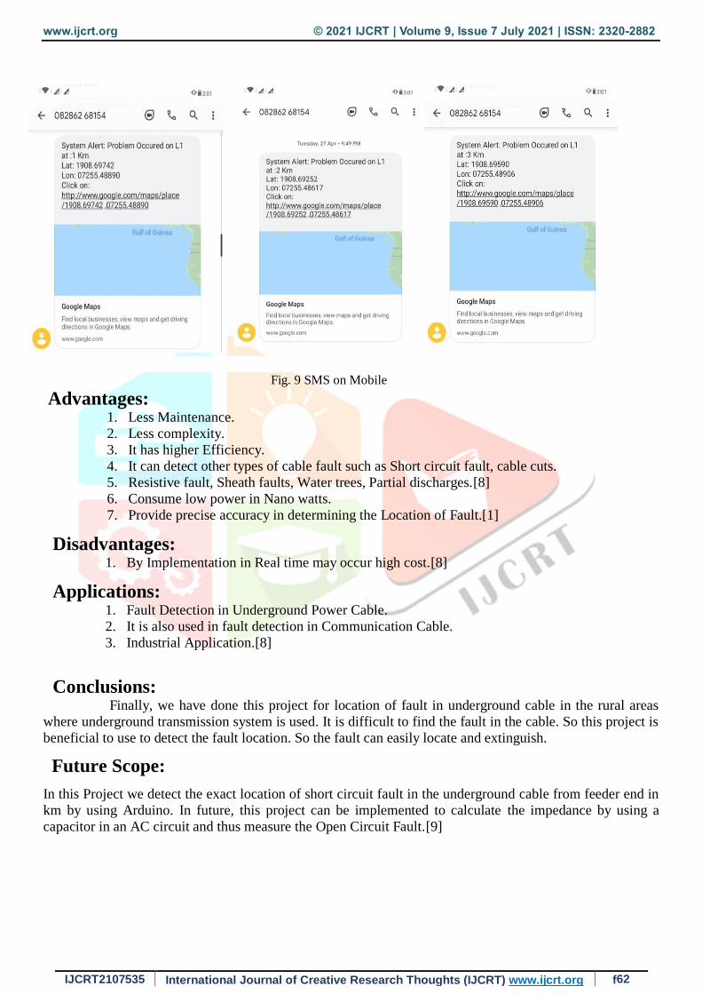
Result:
After getting the Fault location data it is sent to Mobile Number using GSM Module. The SMS
includes distance of location and its coordinates as link and using this link the Fault location can be clearly
monitored using Google Maps.
Fig. 8 Project Circuit
www.ijcrt.org © 2021 IJCRT | Volume 9, Issue 7 July 2021 | ISSN: 2320-2882
IJCRT2107535 International Journal of Creative Research Thoughts (IJCRT) www.ijcrt.org f62
Fig. 9 SMS on Mobile
Advantages: 1. Less Maintenance.
2. Less complexity.
3. It has higher Efficiency.
4. It can detect other types of cable fault such as Short circuit fault, cable cuts.
5. Resistive fault, Sheath faults, Water trees, Partial discharges.[8]
6. Consume low power in Nano watts.
7. Provide precise accuracy in determining the Location of Fault.[1]
Disadvantages: 1. By Implementation in Real time may occur high cost.[8]
Applications: 1. Fault Detection in Underground Power Cable.
2. It is also used in fault detection in Communication Cable.
3. Industrial Application.[8]
Conclusions: Finally, we have done this project for location of fault in underground cable in the rural areas
where underground transmission system is used. It is difficult to find the fault in the cable. So this project is
beneficial to use to detect the fault location. So the fault can easily locate and extinguish.
Future Scope:
In this Project we detect the exact location of short circuit fault in the underground cable from feeder end in
km by using Arduino. In future, this project can be implemented to calculate the impedance by using a
capacitor in an AC circuit and thus measure the Open Circuit Fault.[9]
www.ijcrt.org © 2021 IJCRT | Volume 9, Issue 7 July 2021 | ISSN: 2320-2882
IJCRT2107535 International Journal of Creative Research Thoughts (IJCRT) www.ijcrt.org f63
Reference:
[1]. Special Issue of International Journal of Electronics, Communication & Soft Computing Science and
Engineering IETE Zonal seminar “Recent Trends in Engineering & Technology”-2017 ISSN:2277-9477.
[2]. International Journal of Engineering Research & Technology (IJERT) ISSN: 2278-0181 Vol. 9 Issue 02,
February-2020 http://www.ijert.org
[3]. International Research Journal of Engineering and Technologies (IRJET) Volume 7, Issue 12, Dec (2020)
www.irjet.net ISSN: 2395-0056.
[4]. International Research Journal of Engineering and Technology (IRJET) Volume 4, Issue 2 Feb 2017
www.irjet.net ISSN: 2395-0056
[5]. IOT based Underground Cable Fault Detection www.nevonprojects.com
[6]. Thomas, Summi & A.Vimenthani, & Kaleeswari,. (2017). Automatic underground cable fault locator
using GSM. International Journal of Advanced Research Trends in Engineering and Technology (IJARTET).
4. 260-265.
[7]. Manickam, Dinesh & Vairaperumal, Mr & Senthil kumar, Mr. (2018). Design and Detection of
Underground Cable Fault Using Raspberry Pi and IOT System. International Journal of Trend in Scientific
Research and Development. Volume-3. 668-672. 10.31142/ijtsrd19037
[8]. International Journal of Advanced Research in Management, Architecture, Technology and
Engineering (IJARMATE) Volume 5,Issue 3, March 2019 www.ijarmate.com ISSN:2454-9762
[9]. International Journals of Innovations in Engineering Research and Technology [IJIERT] ISSN: 2394-
3696 Volume 2, ISSUE 4APR.-2015.
Related Documents


