Underbalanced drilling (UBD) In underbalanced drilling (UBD), the hydrostatic head of the drilling fluid is intentionally designed to be lower than the pressure of the formations that are being drilled. The hydrostatic head of the fluid may naturally be less than the formation pressure, or it can be induced by adding different substances to the liquid phase of the drilling fluid, such as: Natural gas Nitrogen Air Whether the underbalanced status is induced or natural, the result may be an influx of formation fluids that must be circulated from the well, and controlled at surface. Characteristics of UBD The effective downhole circulating pressure of the drilling fluid is equal to the hydrostatic pressure of the fluid column, plus associated friction pressures, plus any pressure applied on surface. Conventionally, wells are drilled overbalanced. In these wells, a column of fluid of a certain density in the hole provides the primarywell-control mechanism. The pressure on the bottom of the well will always be designed to be higher than the pressure in the formation (Fig. 1a). In underbalanced drilled wells, a lighter fluid replaces the fluid column, and the pressure on the bottom of the well is designed intentionally to be lower than the pressure in the formation (Fig. 1b). Fig. 1a—Pressures in conventional drilling.

Welcome message from author
This document is posted to help you gain knowledge. Please leave a comment to let me know what you think about it! Share it to your friends and learn new things together.
Transcript
Underbalanced drilling (UBD)
In underbalanced drilling (UBD), the hydrostatic head of the drilling fluid is intentionally designed to be lower than
the pressure of the formations that are being drilled. The hydrostatic head of the fluid may naturally be less than
the formation pressure, or it can be induced by adding different substances to the liquid phase of the drilling fluid,
such as:
Natural gas
Nitrogen
Air
Whether the underbalanced status is induced or natural, the result may be an influx of formation fluids that must
be circulated from the well, and controlled at surface.
Characteristics of UBD
The effective downhole circulating pressure of the drilling fluid is equal to the hydrostatic pressure of the fluid
column, plus associated friction pressures, plus any pressure applied on surface.
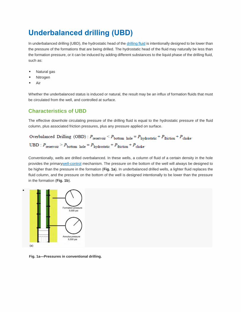
Conventionally, wells are drilled overbalanced. In these wells, a column of fluid of a certain density in the hole
provides the primarywell-control mechanism. The pressure on the bottom of the well will always be designed to
be higher than the pressure in the formation (Fig. 1a). In underbalanced drilled wells, a lighter fluid replaces the
fluid column, and the pressure on the bottom of the well is designed intentionally to be lower than the pressure
in the formation (Fig. 1b).
Fig. 1a—Pressures in conventional drilling.

Fig. 1b—Pressures in underbalanced drilling.
Because the fluid no longer acts as the primary well-control mechanism, the primary well control in UBD arises
from three different mechanisms:
Hydrostatic pressure (passive) of materials in the wellbore because of the density of the fluid used (mud)
and the density contribution of any drilled cuttings.
Friction pressure (dynamic) from fluid movement because of circulating friction of the fluid used.
Choke pressure (confining or active), which arises because of the pipe being sealed at surface, resulting in
a positive pressure at surface.
Flow from any porous and permeable zones is likely to result when drilling underbalanced. This inflow of formation
fluids must be controlled, and any hydrocarbon fluids must be handled safely at surface.
The lower hydrostatic head avoids the buildup of filter cake on the formation as well as the invasion of mud and
drilling solids into the formation. This helps to improve productivity of the well and reduce related drilling problems.
UBD produces an influx of formation fluids that must be controlled to avoid well-control problems. This is one of
the main differences from conventional drilling. In conventional drilling, pressure control is the main well control
principle, while in UBD, flow control is the main well-control principle. In UBD, the fluids from the well are returned
to a closed system at surface to control the well. With the well flowing, the blowout preventer (BOP) system is
kept closed while drilling, whereas, in conventional overbalanced operations, drilling fluids are returned to an
open system with the BOPs open to atmosphere (Fig. 2). Secondary well control is still provided by the BOPs,
as is the case with conventional drilling operations.

Fig. 2—Open vs. closed circulation systems.
Lowhead drilling
Lowhead drilling is drilling with the hydrostatic head of the drilling fluid reduced to a pressure marginally higher
than the pressure of the formations being drilled. The hydrostatic head of the fluid is maintained above the
formation pressure, and reservoir inflow is avoided. Lowhead drilling may be undertaken in formations that would
produce H2S, or would cause other issues, if hydrocarbons were produced to surface.
Reasons to consider underbalanced drilling
The reasons for UBD can be broken down into two main categories:
Maximizing hydrocarbon recovery.
Minimizing pressure-related drilling problems.
There are also specific advantages and disadvantages of performing a drilling operation underbalanced. These
are summarized inTable 1.
Table 1-Advantages vs. disadvantages of UBD
Maximizing hydrocarbon recovery
There is no invasion of solids or mud filtrate into the reservoir formation. This often eliminates the requirement
for any well cleanup after drilling is completed.
Early production
The well is producing as soon as the reservoir is penetrated with a bit. This could also be a disadvantage if
hydrocarbon production cannot be handled or stored on site, or if the required export lines are not available.
Reduced stimulation
Because there is no filtrate or solids invasion in an underbalanced drilled reservoir, the need for reservoir
stimulation, such as acid washing or massive hydraulic fracture stimulation, is eliminated.
Enhanced recovery
Because of the increased productivity of an underbalanced drilled well combined with the ability to drill infill wells
in depleted fields, the recovery of bypassed hydrocarbons is possible. This can significantly extend the life of a
field. The improved productivity of the wells also leads to a lower drawdown, which, in turn, can reduce water
coning.
Increased reservoir knowledge
During an underbalanced drilling operation, reservoir productivity and the produced fluids can be measured and
analyzed while drilling. This allows a well to be drilled longer or shorter, depending on production requirements.
An operator is also able to determine the most productive zones in a reservoir in real time, and obtain well test
results while drilling.
Skin factors on most underbalanced drilled wells are negative, just as they are in wells drilled and stimulated.
Minimizing pressure-related drilling problems
Differential sticking
The absence of an overburden on the formation combined with the lack of any filter cake serves to prevent the
drillstring from becoming differentially stuck. This is especially useful when drilling with coiled tubing,
because coiled tubing lacks tool joint connections that increase the standoff in the borehole and then helps
minimize sticking of conventional drillpipe.
No losses
In general, a reduction of the hydrostatic pressure in the annulus reduces the fluid losses into a reservoir
formation. In UBD, the hydrostatic pressure is reduced to a level at which losses do not occur. This is especially
important in the protection of fractures in a reservoir.
Improved penetration rate
The lowering of the wellbore pressure relative to the formation pressure has a significant effect on penetration
rate. The reduction in the “chip holddown effect” also has a positive impact on bit life. The increased penetration
rate combined with the effective cuttings removal from the face of the bit leads to a significant increase in bit life.
In underbalanced drilled wells, sections have been drilled with only one bit where an overbalanced drilled well
might need anywhere from three to five bits. It is normally assumed that penetration rates double when drilling
underbalanced.
Classification system for underbalanced drilling
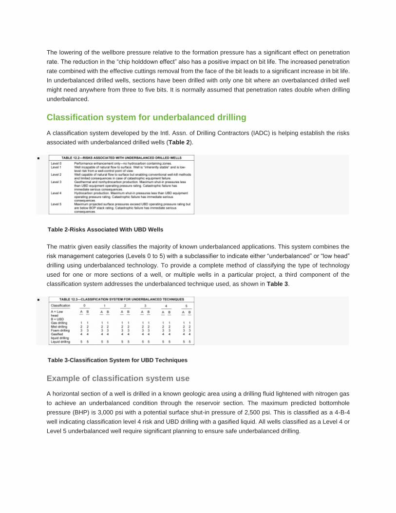
A classification system developed by the Intl. Assn. of Drilling Contractors (IADC) is helping establish the risks
associated with underbalanced drilled wells (Table 2).
Table 2-Risks Associated With UBD Wells
The matrix given easily classifies the majority of known underbalanced applications. This system combines the
risk management categories (Levels 0 to 5) with a subclassifier to indicate either “underbalanced” or “low head”
drilling using underbalanced technology. To provide a complete method of classifying the type of technology
used for one or more sections of a well, or multiple wells in a particular project, a third component of the
classification system addresses the underbalanced technique used, as shown in Table 3.
Table 3-Classification System for UBD Techniques
Example of classification system use
A horizontal section of a well is drilled in a known geologic area using a drilling fluid lightened with nitrogen gas
to achieve an underbalanced condition through the reservoir section. The maximum predicted bottomhole
pressure (BHP) is 3,000 psi with a potential surface shut-in pressure of 2,500 psi. This is classified as a 4-B-4
well indicating classification level 4 risk and UBD drilling with a gasified liquid. All wells classified as a Level 4 or
Level 5 underbalanced well require significant planning to ensure safe underbalanced drilling.
Selecting the right candidate for UBD
Most reservoirs can be drilled underbalanced, but some cannot, because of geological issues associated with
rock stability. For some reservoirs, it might not be possible to drill underbalanced with the current technology,
because they are either prolific producers, or pressures are so high that safety and environmental concerns
prevent safe underbalanced drilling. These may include high-pressure or sour wells (although both types have
been drilled underbalanced, but with significant engineering considerations and planning).
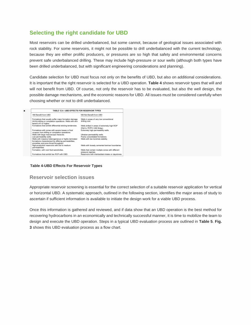
Candidate selection for UBD must focus not only on the benefits of UBD, but also on additional considerations.
It is important that the right reservoir is selected for a UBD operation. Table 4 shows reservoir types that will and
will not benefit from UBD. Of course, not only the reservoir has to be evaluated, but also the well design, the
possible damage mechanisms, and the economic reasons for UBD. All issues must be considered carefully when
choosing whether or not to drill underbalanced.
Table 4-UBD Effects For Reservoir Types
Reservoir selection issues
Appropriate reservoir screening is essential for the correct selection of a suitable reservoir application for vertical
or horizontal UBD. A systematic approach, outlined in the following section, identifies the major areas of study to
ascertain if sufficient information is available to initiate the design work for a viable UBD process.
Once this information is gathered and reviewed, and if data show that an UBD operation is the best method for
recovering hydrocarbons in an economically and technically successful manner, it is time to mobilize the team to
design and execute the UBD operation. Steps in a typical UBD evaluation process are outlined in Table 5. Fig.
3 shows this UBD evaluation process as a flow chart.
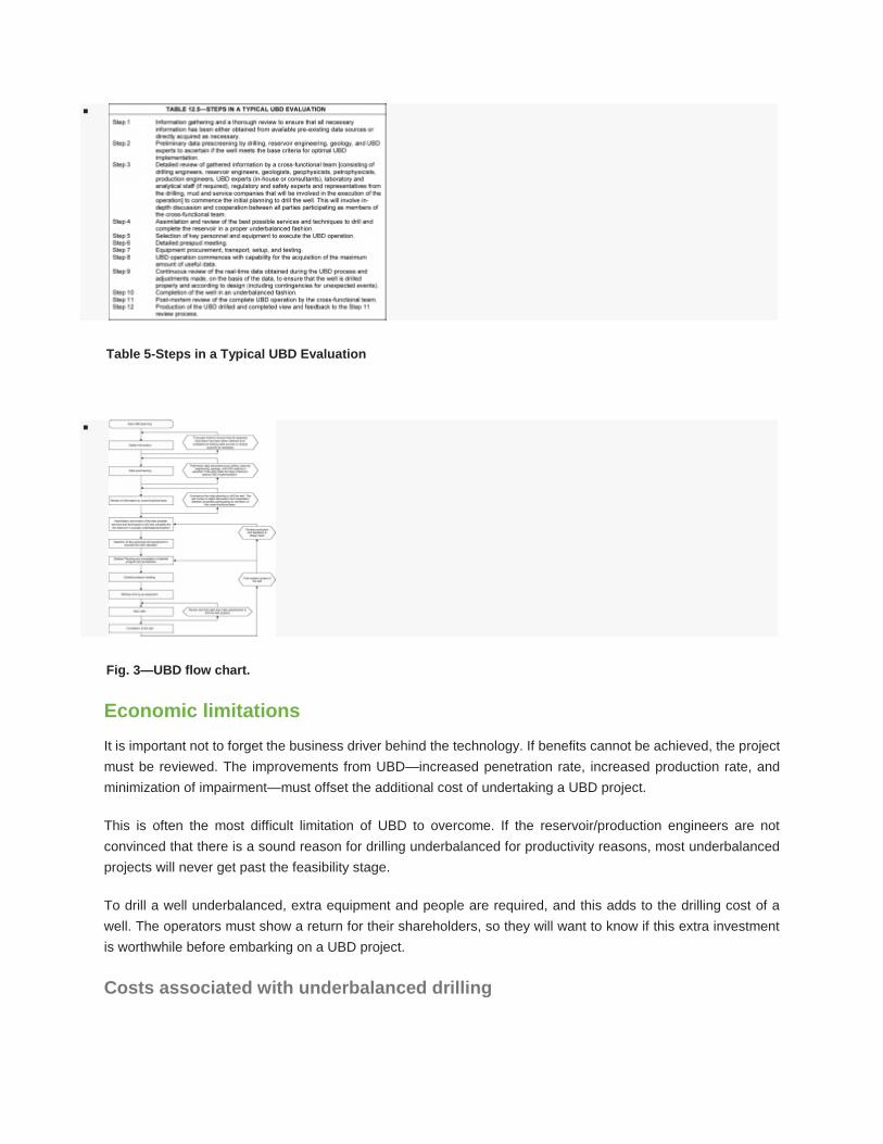
Table 5-Steps in a Typical UBD Evaluation
Fig. 3—UBD flow chart.
Economic limitations
It is important not to forget the business driver behind the technology. If benefits cannot be achieved, the project
must be reviewed. The improvements from UBD—increased penetration rate, increased production rate, and
minimization of impairment—must offset the additional cost of undertaking a UBD project.
This is often the most difficult limitation of UBD to overcome. If the reservoir/production engineers are not
convinced that there is a sound reason for drilling underbalanced for productivity reasons, most underbalanced
projects will never get past the feasibility stage.
To drill a well underbalanced, extra equipment and people are required, and this adds to the drilling cost of a
well. The operators must show a return for their shareholders, so they will want to know if this extra investment
is worthwhile before embarking on a UBD project.
Costs associated with underbalanced drilling
The following factors contribute to the cost increases for an underbalanced drilled well in comparison to a
conventionally drilled well:
Pre-engineering studies.
Rotating diverter system.
Surface separation and well-control package.
Snubbing system to deal with pipe light.
Data acquisition system.
Extra downhole equipment [nonreturn valves and pressure while drilling (PWD)].
Special drillstring connections (high-torque gas that is tight with special hardbanding).
Additional personnel training.
Additional operational wellsite personnel.
Additional safety case update consistent with planned UBD operations.
Extra time required to drill underbalanced.
From industry experience to date, we can state that underbalanced drilled wells are 20 to 30% more expensive
than overbalanced drilled wells. This applies to both offshore and onshore operations in a similar area.
Cost alone, however, is not a good measure for the evaluation of UBD. The value of the well must also be
recognized. The average three-fold increase in productivity of an underbalanced drilled well can add considerable
value to a field development plan or a field rehabilitation program. If we add a potential increased recovery from
a field to the value of an underbalanced well, even an increase as small as 1% in total hydrocarbon recovery
may have a large impact on field economics.
Reservoir studies
Prior to a UBD operation, some reservoir engineering work should be carried out. Not only is an accurate reservoir
pressure needed, but the damage mechanism of the reservoir must be understood to ensure that the benefits of
UBD can be obtained. Some wells or reservoirs are suitable for underbalanced operations, and result in an
enhanced recovery. Other formations or fields may not be viable for a variety of reasons. If formation damage is
the main driver for UBD, it is important that the reservoir and petroleum engineers understand the damage
mechanisms resulting from overbalanced drilling (OBD). We must remember that even underbalanced drilled
wells can cause formation damage.
Coreflush testing may be required to establish compatibility between the proposed drilling fluid and the produced
reservoir fluids. This is critical if oil reservoirs are to be drilled underbalanced. The potential for scale and emulsion
forming must also be reviewed prior to starting operations. We must ascertain the stability of the zone of interest
to determine if the proposed well path is structurally capable of being drilled with the anticipated formation
drawdown.
Expected productivity with the proposed drawdown must be reviewed. The objective of UBD is to clean the
reservoir, and not to produce the well to its maximum capacity. If the reservoir is likely to produce any water, we
must take this into account because water influx can have significant effects on the underbalanced process. It is
important that expected productivity be analyzed with the reservoir engineers to obtain an accurate indicator as
to whether UBD would be beneficial.

Once reservoir issues are fully understood, advantages to drilling underbalanced are proven, and the proposed
well profile can be achieved, we can undertake the selection of the surface equipment.
Underbalanced drilling limitations
There are limitations, as well as advantages, to underbalanced drilling (UBD). Before embarking on a UBD
program, the limitations of the process must be reviewed.
Factors that negatively affect underbalanced drilling
There are technical limitations as well as safety and economic limitations to the UBD process. The following are
conditions that can adversely affect any underbalanced operation:
Insufficient formation strength to withstand mechanical stress without collapse.
Spontaneous imbibitions because of incompatibility between the base fluid used in the UBD fluid and the
rock or reservoir fluid. Use of a nonwetting fluid can prevent or reduce this situation.
Deep, high-pressure, highly permeable wells presently represent a technical boundary because of well
control and safety issues.
Noncontinuous underbalanced conditions.
Excessive formation water.
High-producing zones close to the beginning of the well trajectory will adversely affect the underbalanced
conditions along the borehole.
Wells that require hydrostatic fluid or pressure to kill the well during certain drilling or completion operations.
Slimhole or drilling conditions that result in a small annulus create high backpressures because of frictional
forces.
Wells that contain targets with significant pressure or lithology variations throughout.
Technical limitations
Wellbore Stability
Wellbore stability is one of the main limitations of UBD. Borehole collapse as the result of rock stresses is one
issue to consider. The other issue is chemical stability, which is a problem seen in shale and claystone formations.
Both these issues can have serious implications in UBD. Defining maximum drawdown and reviewing chemical
compatibility with the proposed drilling fluids is a key issue in the feasibility of UBD.
Water inflow
Water inflow in a depleted reservoir can cause severe problems in an underbalanced drilled well. If the flow rate
is high enough, the well will be killed as a result of the water influx. Gas lifting a well that produces water at a
high rate is almost impossible. Care must be taken that the water leg in a depleted reservoir is not penetrated
when drilling underbalanced.
Directional drilling equipment
Directional drilling equipment can have limitations on UBD. Hydraulic operated tools cannot be used in
underbalanced wells, and if a gasified system is used, the measurement while drilling (MWD) pulse systems may
not work. Certain motors and other directional equipment may be prone to failure as a result of the rubber
components becoming impregnated with the gas used. Explosive decompression of rubber components is a
consideration when selecting equipment.
The higher torque and drag seen in underbalanced wells (as much as 20 to 100%) may prevent certain
trajectories from being drilled underbalanced. The higher torque is caused by the reduced buoyancy combined
with the lack of filter cake on the borehole wall.
Unsuitable reservoir
The reservoir may not be suitable for UBD. A highly porous, high-permeability reservoir can provide too much
inflow at low drawdown. It is important that the perceived benefits of UBD are kept in mind when planning for
underbalanced operations.
Safety and environment
The health, safety, and environment issues of a UBD operation may prove to be too complicated to allow UBD
to proceed.
Surface equipment
The placement of the surface equipment may prove to be impossible on some offshore locations. There can be
problems with rig-floor height and with deck space or deck loading. Both the wellhead equipment and the surface
separation equipment must be carefully designed to fit the platform or rig.
Surface equipment for UBD operations
Selecting surface equipment is the final step in designing an underbalanced drilling (UBD) operation. The surface
equipment for UBD can be broken down into four categories:
Drilling system
Gas-generation equipment
Well-control equipment
Surface separation equipment.
Drilling systems
Hole size and reservoir penetration, as well as directional trajectory, determine whether coiled tubing or jointed
pipe is the optimal drillstring medium (Table 1). If the hole size required is larger than 6⅛ in., jointed pipe may
need to be used. For hole sizes of 6⅛ in. or smaller, coiled tubing can be considered. The size of coiled tubing
currently used for drilling operations is between 2 and 2⅞ in. outer diameter (OD). This is because of many
factors, including:
The flow rate through the coil
Pressure drop through the tubing
Weight on bit (WOB)
Profile of the well
Maximum pickup weight
Both in-hole and surface equipment
Weight of the coiled tubing itself
Occasionally, the ideal coiled tubing for an operation may be excluded because of such factors as crane or
transport limitations or that the life of the coil may not be economical. Generally, coiled tubing has several
advantages and disadvantages compared to jointed pipe systems. For jointed pipe systems, drillstring properties
and tripping under pressure must be considered. If hole size and trajectory permit, coiled tubing is the simplest
system to drill underbalanced.
Table 1-Relative Merits of Coiled Tubing Vs. Jointed Pipe
Gas-generation equipment
Natural gas
If natural gas is used for UBD, a natural gas compressor may be required. This would need to be reviewed once
the source of the gas is known. Most production platforms have a source of high-pressure gas, and, in this
situation, a flow regulator and pressure regulator are required to control the amount of gas injected during the
drilling process.
Cryonic generation
The use of tanked nitrogen could be considered on onshore locations, where a large truck could be used for its
supply. Cryogenic nitrogen in 2,000-gal transport tanks provides high-quality nitrogen and utilizes equipment that
is generally less expensive. Liquid nitrogen is passed through the nitrogen converter, where the fluid is pumped
under pressure prior to being converted to gas. The gas is then injected into the string. Generally, the requirement
is for the nitrogen converter and a work tank, with additional tanks being provided as necessary. For operations
in excess of 48 hours, the requirement for liquid nitrogen could be quite large, and this can result in logistical

difficulties. To move away from tank transport for large nitrogen-dependent drilling operations, the use of nitrogen
generators is often recommended offshore.
Nitrogen generation
A nitrogen generator is no more than a filtering system that filters nitrogen out of the atmosphere. A nitrogen
generator uses small membranes to filter the air. Oxygen-enriched air is vented to the atmosphere, and nitrogen
is boosted to the required injection pressure. Fig. 1 shows a nitrogen-generation system.
Fig. 1—A nitrogen generating system.
A nitrogen generator is 50% efficient. In real terms, if 1,500 ft 2 /min of nitrogen is required, then 3,000 ft 2 /min
of air needs to be pumped into the generator. A full nitrogen system for 1,500 ft 2 /min would comprise of three
or four large air compressors, a nitrogen generator, and a booster compressor. This equipment will take up
significant deck space on an offshore rig or platform.Fig. 2 shows the nitrogen generation equipment rigged up
on a jackup.
Fig. 2—Offshore nitrogen generating system.
Another issue associated with nitrogen generation is the purity of the nitrogen itself. Purity varies depending on
the amount of nitrogen required. At 95% purity (by mole), 5% oxygen is delivered. Although this is not enough
oxygen to reach explosive levels, it is sufficient oxygen to cause corrosion problems. The corrosion is worsened
when salt brine systems are used at elevated temperatures (Fig. 3).

Fig. 3—Onshore nitrogen generator and compressors.
Well-control equipment
Jointed-pipe systems
The conventional blowout preventer (BOP) stack used for drilling is not compromised during UBD operations.
The conventional BOP stack is not used for routine operations, and is not used to control the well except in the
case of an emergency (Fig. 4).
Fig. 4—Typical BOP stack-up.
A rotating control-head system and primary flowline with emergency shut down (ESD) valves is installed on top
of the conventional BOP. If required, a single blind ram, operated by a special Koomey unit, is installed under
the BOP stack to allow the drilling bottomhole assembly (BHA) to be run under pressure.
Coiled-tubing systems
Well control is much simpler when drilling with reeled systems. A lubricator can be used to stage in the main
components of the BHA, or, if a suitable downhole safety valve can be used, then a surface lubricator is not
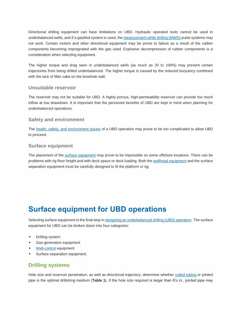
required. The injector head can then be placed directly on top of the wellhead system (Fig. 5).
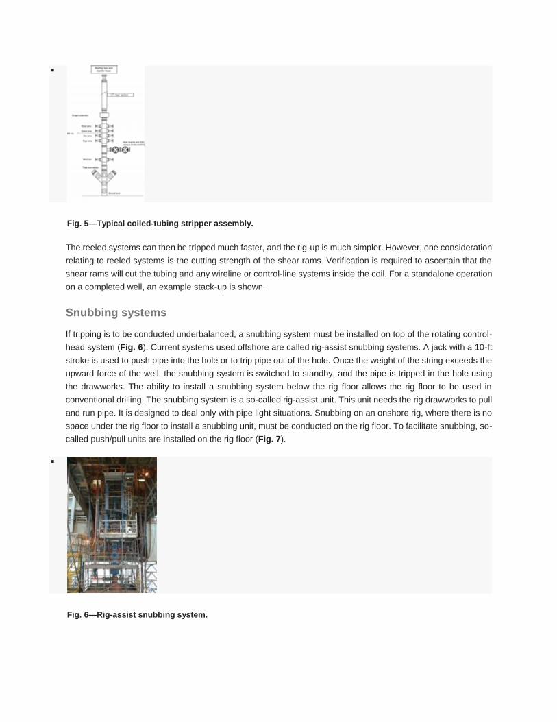
Fig. 5—Typical coiled-tubing stripper assembly.
The reeled systems can then be tripped much faster, and the rig-up is much simpler. However, one consideration
relating to reeled systems is the cutting strength of the shear rams. Verification is required to ascertain that the
shear rams will cut the tubing and any wireline or control-line systems inside the coil. For a standalone operation
on a completed well, an example stack-up is shown.
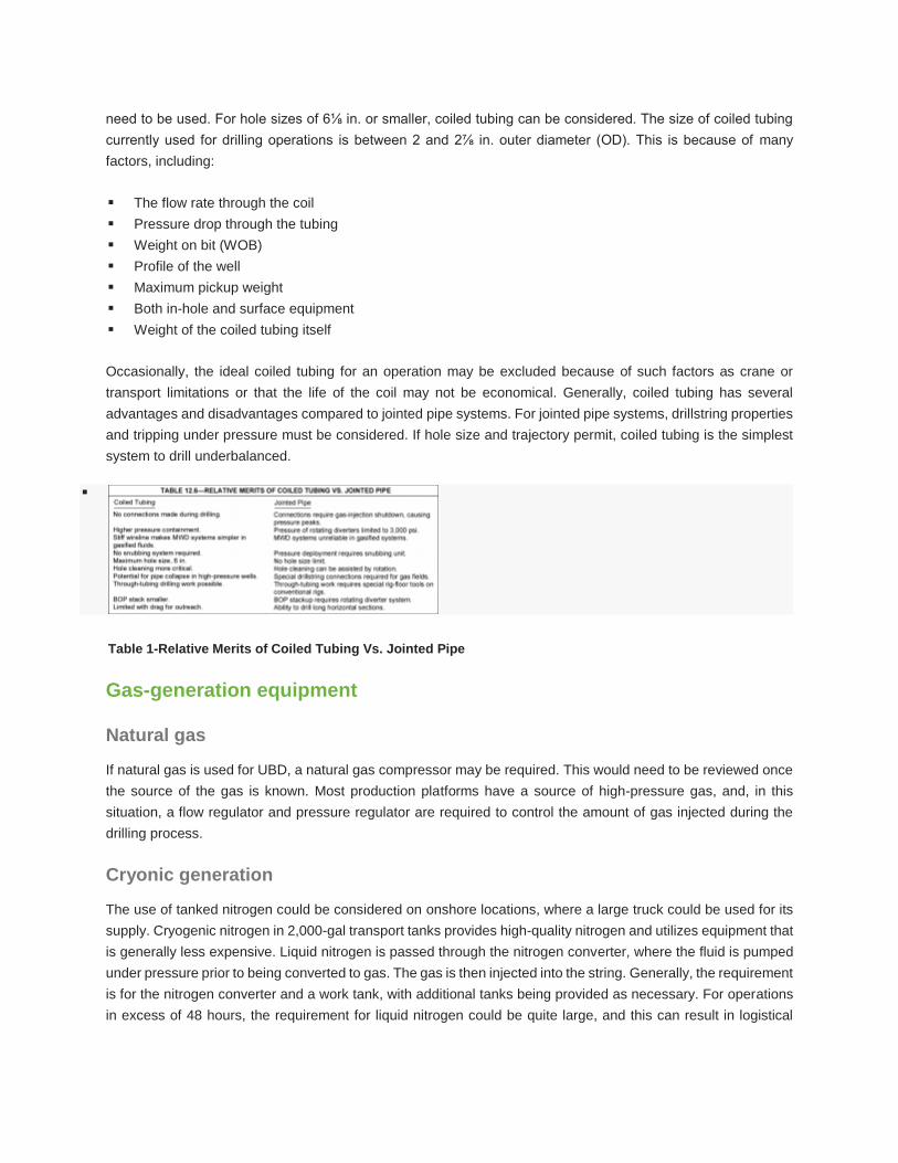
Snubbing systems
If tripping is to be conducted underbalanced, a snubbing system must be installed on top of the rotating control-
head system (Fig. 6). Current systems used offshore are called rig-assist snubbing systems. A jack with a 10-ft
stroke is used to push pipe into the hole or to trip pipe out of the hole. Once the weight of the string exceeds the
upward force of the well, the snubbing system is switched to standby, and the pipe is tripped in the hole using
the drawworks. The ability to install a snubbing system below the rig floor allows the rig floor to be used in
conventional drilling. The snubbing system is a so-called rig-assist unit. This unit needs the rig drawworks to pull
and run pipe. It is designed to deal only with pipe light situations. Snubbing on an onshore rig, where there is no
space under the rig floor to install a snubbing unit, must be conducted on the rig floor. To facilitate snubbing, so-
called push/pull units are installed on the rig floor (Fig. 7).
Fig. 6—Rig-assist snubbing system.

Fig. 7—Push/pull snubbing machine.
Rotating diverter systems
The principle use of the rotating diverter system is to provide an effective annular seal around the drillpipe during
drilling and tripping operations. The annular seal must be effective for a wide range of pressures, and for a variety
of equipment sizes and operational procedures. The rotating control-diverter system achieves this by packing off
around the drill pipe. The rotating control-head system consists of a pressure-containing housing where packer
elements are supported between roller bearings and isolated by mechanical seals.
Types of rotating diverter
There are currently two types of rotating diverter: active and passive.
Diverter Type Description
Active Rotating
Diverter
The active type uses external hydraulic pressure to activate the sealing mechanism
and increase the sealing pressure as the annular pressure increases
Passive Rotating
Diverter
The passive type, normally referred to as rotating control-head systems, uses a
mechanical seal
All surface BOP systems have limitations in both the amount of pressure they can seal off, and in the degradation
of the sealing equipment from the flow and composition of the different reservoir fluids and gases over time,
regardless of the type of surface BOP control system chosen.
Rotating control heads (passive systems)
Rotating control heads are passive sealing systems (Fig. 8). Rotating control heads have given excellent service
for more than 30 years, particularly in the air and air-foam drilling industry. The rotating control head is playing
an increasingly important role in UBD, provided that its inherent pressure limitations are not being extended. The
conventional, original rotating control head was developed in the 1960s. This is a low-pressure model and has
been used on thousands of underbalanced and overbalanced drilled wells. It is designed to operate at 500 psi
rotating and 1,000 psi static. It is capable of rotating up to 200 rpm and uses a single stripper rubber. It is currently
used in many underbalanced operations in the United States. The current rotating control heads are rated to a
static pressure of 5,000 psi and a rotating pressure of 3,000 psi with 100 rpm.
Fig. 8—Rotating control head.
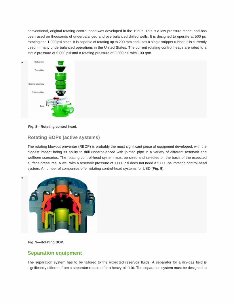
Rotating BOPs (active systems)
The rotating blowout preventer (RBOP) is probably the most significant piece of equipment developed, with the
biggest impact being its ability to drill underbalanced with jointed pipe in a variety of different reservoir and
wellbore scenarios. The rotating control-head system must be sized and selected on the basis of the expected
surface pressures. A well with a reservoir pressure of 1,000 psi does not need a 5,000-psi rotating control-head
system. A number of companies offer rotating control-head systems for UBD (Fig. 9).
Fig. 9—Rotating BOP.
Separation equipment
The separation system has to be tailored to the expected reservoir fluids. A separator for a dry-gas field is
significantly different from a separator required for a heavy-oil field. The separation system must be designed to
handle the expected influx, and it must be able to separate the drilling fluid from the return well flow so that it can
be pumped down the well once again.
The surface separation system in UBD can be compared with a process plant, and there are many similarities
with the process industry. Fluid streams while drilling underbalanced are often described as four-phase flow
because the return flow comprises of oil, water, gas, and solids.
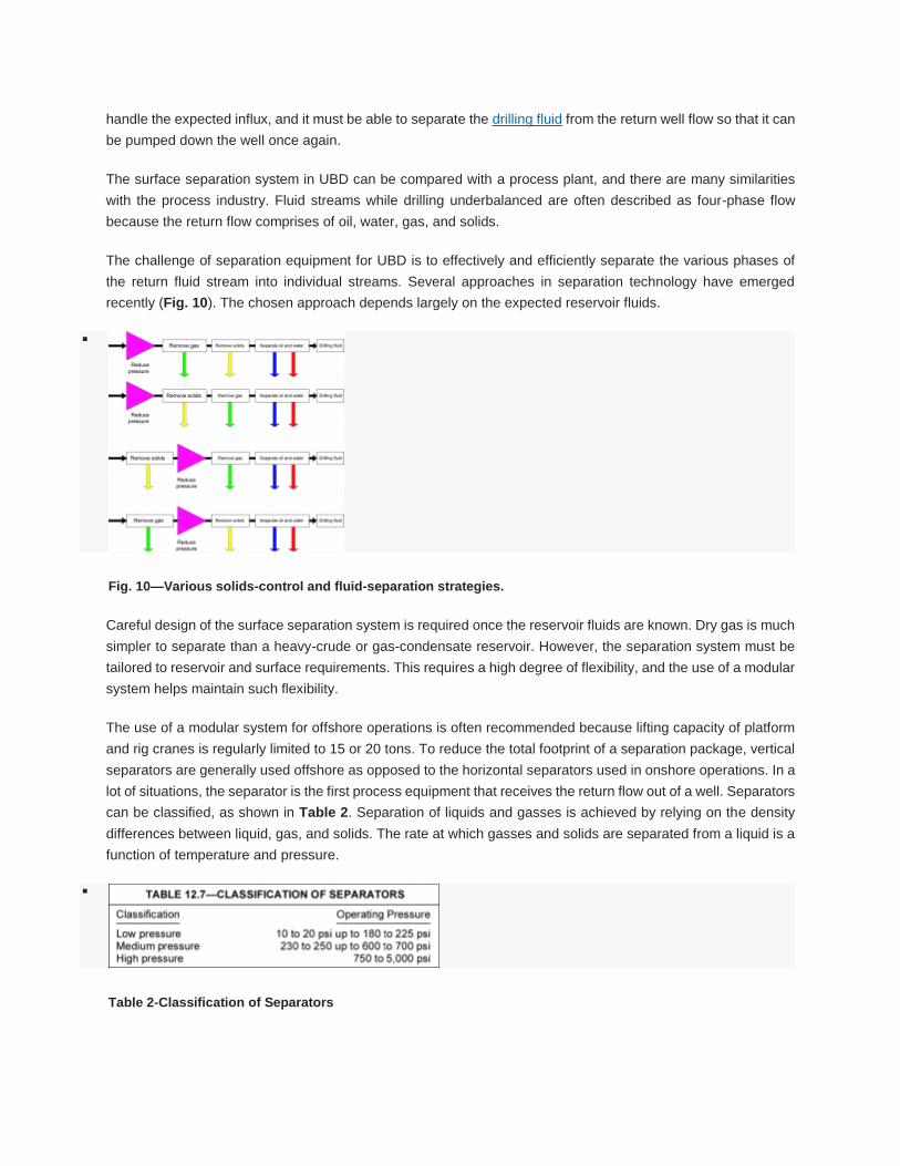
The challenge of separation equipment for UBD is to effectively and efficiently separate the various phases of
the return fluid stream into individual streams. Several approaches in separation technology have emerged
recently (Fig. 10). The chosen approach depends largely on the expected reservoir fluids.
Fig. 10—Various solids-control and fluid-separation strategies.
Careful design of the surface separation system is required once the reservoir fluids are known. Dry gas is much
simpler to separate than a heavy-crude or gas-condensate reservoir. However, the separation system must be
tailored to reservoir and surface requirements. This requires a high degree of flexibility, and the use of a modular
system helps maintain such flexibility.
The use of a modular system for offshore operations is often recommended because lifting capacity of platform
and rig cranes is regularly limited to 15 or 20 tons. To reduce the total footprint of a separation package, vertical
separators are generally used offshore as opposed to the horizontal separators used in onshore operations. In a
lot of situations, the separator is the first process equipment that receives the return flow out of a well. Separators
can be classified, as shown in Table 2. Separation of liquids and gasses is achieved by relying on the density
differences between liquid, gas, and solids. The rate at which gasses and solids are separated from a liquid is a
function of temperature and pressure.
Table 2-Classification of Separators

Horizontal and vertical separators can be used. Vertical separators are more effective when the returns are
predominantly liquid, while horizontal separators have higher and more efficient gas handling capacities. In
horizontal separators, well returns enter and are slowed by the velocity-reducing baffles (Figs. 11 and 12).
Fig. 11—Horizontal separator.
Fig. 12—Vertical separator.
Data acquisition
The data acquisition used on the separation system should provide the maximum amount of information about
the reservoir obtainable while drilling. It should allow for a degree of well testing during drilling. Furthermore, the
safety value of data acquisition should not be overlooked because well control is related directly to the pressures
and flow rates seen at surface.
Erosion monitoring
Erosion monitoring and prediction of erosion on pipe work is essential for safe operations. The use of
nondestructive testing technology has been found to be insufficient in erosion monitoring. An automated system
using erosion probes is currently deployed, and this allows accurate prediction of erosion rates in surface pipe
work.

Downhole equipment for UBD operations
Successful underbalanced drilling (UBD) requires downhole equipment to provide real-time information to the
surface for monitoring conditions during drilling operations.
Pressure while drilling (PWD) sensors
Pressure while drilling (PWD) sensors have proved invaluable in every UBD operation to date, when they have
been included in the drillstring and operated without downtime. However, quite a number of these sensors have
proved problematic, because of the vibration problems and fast drilling rates encountered with UBD. Adding a
downhole gauge or sensor on the injection side and in the drillstring has a few of the following benefits: enhanced
UBD operation, help optimize the drilling process, and increase the operator’s knowledge of the reservoir.
Conventional measurement while drilling (MWD) tools in UBD
The most common technique for transmitting measurement while drilling (MWD) data uses the drilling fluid
pumped down through the drillstring as a transmission medium for acoustic waves. Mud-pulse telemetry
transmits data to the surface by modifying the flow of mud in the drillpipe in such a way that there are changes
in fluid pressure at surface. It involves the sequential operation of a downhole mechanism to selectively vary or
modulate the dynamic flowing pressure in the drillstring, and sends the real-time data gathered by the downhole
sensors. This variation in the dynamic pressure is detected at the surface, where it is demodulated back into the
real measurements and parameters from the downhole sensors.
Signal strength at the surface depends on many factors including, but not limited to:
The mud properties
Drillstring arrangement
Flow rate
Signal strength generated at the tool
Telemetry frequency
Experience to date indicates that this enhanced mud-pulse telemetry system is best applied to scenarios with a
maximum gas percentage of 20% (by volume at the standpipe), and this ratio can be extended somewhat
depending on a number of factors, including:
Well depth
Profile
Liquid-phase fluid
Drillstring/bottomhole assembly (BHA)
Pumping pressure
Flow rates.
Further reductions in borehole pressure are possible with gas lift applications in which N2 is injected into the
annulus. A major disadvantage of the mud pulse is that it will not work if high-quality foam is needed. For such
fluids, an electromagnetic method must be used.
If annular gas injection is used, we have a single-phase fluid down the drillstring, and conventional MWD systems
can be used. If drillstring gas injection is considered, the option of using electromagnetic MWD tools must be
considered.
Electromagnetic measurement while drilling (EMWD)
Electromagnetic telemetry transmits data to the surface by pulsing low-frequency waves through the Earth. The
first application of PWD measurements has been primarily for drilling and mud performance, kick detection, and
equivalent circulating density (ECD) monitoring.
Nonreturn valves
Float valves are necessary for UBD to prevent influx of reservoir fluids inside the drillstring either when tripping
or making connections. It must be recognized that there is pressure below nonreturn valves. The positions of the
float valve in the drillstring depend on the tools in the bottomhole assembly (BHA) and the policy of the operating
philosophy underpinning the safety management of the operation. The number of float valves in the BHA and the
drillstring is also a matter of company policy consistent with perceived risks and management thereof. If the
drilling float valve(s) should all fail, the well may have to be circulated to kill weight fluid, and a string trip
undertaken to replace or repair the float valves.
It is good practice to install a float valve in the top of the drillstring, often referred to as the string float valve,
because it aids operational efficiency by reducing the time it takes to bleed off the pressure before making
connections while also serving as an additional barrier in the event of a failure of the float valves in the BHA. This
top valve is often a wireline retrievable float valve that can be retrieved, as access through the string is required.
In general, a double float valve is installed just above the BHA, and a further double float valve is installed above
the bit so that there is redundant service. Two types of non-ported drillstring floats that are commonly used are
the flapper and plunger floats.
Deployment valves
The underbalanced deployment valve has been designed to eliminate the need for snubbing operations or the
need to kill the well to trip the drillstring during UBD operations. During UBD operations, the well is allowed to
flow. The result is a flowing or shut-in pressure in the annulus at surface. With any significant pressures while
tripping the drillstring, it has been necessary to either use a snubbing unit or kill the well.
The deployment valve is run as an integral part of the casing program, allowing full-bore passage for the drill bit
when in the open position. When it becomes necessary to trip the drillstring, the string is tripped out until the bit
is above the valve, at which time the deployment valve is closed, and the annulus above the valve bled off. At
this time, the drillstring can be tripped out of the well without the use of a snubbing unit at conventional tripping
speeds, reducing rig time requirements, and providing improved personnel safety. The drillstring can then be
tripped back into the well until the bit is just above the deployment valve. After this is completed, the deployment
valve can be opened, and the drillstring run in to continue drilling operations.
The deployment valve can either be run with the casing using an external casing packer for isolation, or with a
liner hanger and tieback. Once installed, the valve is controlled through pressure applied to the annulus, created
between the intermediate and surface casing. The valve can also be controlled through dual control lines. When
using a snubbing unit, the operator not only has to consider the actual cost of the snubbing service, but should
also include rig-up and rig-down time together with the increased tripping times to determine the overall daily
drilling costs.
Reservoir inflow in underbalanced drilling
In underbalanced drilling (UBD), as soon as the bit penetrates the reservoir, reservoir fluids start to flow into the
wellbore. At this stage, the stabilized multiphase flow regime in the well prior to reservoir fluid entry must be
adjusted to account for inflow and minimize the impact to the circulation system or moving out of the UBD window
already established.
Factors influencing reservoir inflow
The rate of reservoir fluid inflow depends, in part, on the drawdown and reservoir rock properties (the differential
pressure between circulating bottomhole pressure (BHP) and reservoir pressure). There are a number
of models that can be used to estimate the reservoir fluid inflow based on the rock and fluid parameters. However,
the reservoir rock properties are fixed, and the only variable is the drawdown to control reservoir fluid inflow.
Reservoir inflow performance
The inflow performance of a well represents the ability of the reservoir to produce fluids under a given condition
of drawdown. The reservoir fluid inflow performance is the most important parameter in UBD, operationally and
economically, because of its impact on well production and the safety operating envelope.
The intent of drilling any well underbalanced is to:
Create conditions that induce the flow of reservoir fluid into the well while drilling
Minimize reservoir damage
Optimize production of reservoir fluid from the well
Characterize the reservoir
Therefore, the relationship between the BHP and reservoir inflow is one of the most important parameters in UBD
design and management. It is important that the BHP and reservoir inflow rate are managed and maintained
within the defined operating envelope and flow control matrix as defined by the well control strategy. Where the
surface pressure, production rate, or BHP cannot be maintained within appropriate well control levels or
underbalanced, drilling operations must cease immediately and pre-defined well control actions are to be taken.
Related Documents