Under Voltage Load Shedding Incorporating Bus Participation Factor Ardiaty Arief, Muhammad Bachtiar Nappu School of Information Technology and Electrical Engineering, University of Queensland St. Lucia, Brisbane, Australia e-mail:[email protected],[email protected] Zhao Yang Dong Dept. of Electrical Engineering Hong Kong Polytechnic University Hung Hom, Kowloon, Hong Kong e-mail: [email protected] Muhammad Arief Dept. of Electrical Engineering University of Hasanuddin Makassar, Indonesia e-mail: [email protected] Abstract— Under voltage load shedding (UVLS) plays a vital part in power system control when the system is subjected to large disturbances. Load shedding has been employed for long time as the last remedy to preclude major power system failure which is activated by under frequency or under voltage relays. This paper proposes an advanced method for under voltage load shedding incorporating the bus participation factor method to determine the location of load shedding. The main motivation of this study is to attain a better performance of UVLS. The proposed methodology is implemented on a 3-machine 9-bus test system. Dynamic simulation is performed to validate the robustness of the proposed method. Keywords-bus participation factor; modal analysis; under voltage load shedding; voltage stability I. INTRODUCTION Power system stability has been identified as a crucial prerequisite for a safe and trustworthy operation of electricity power system for over the past 80 years [1, 2]. The instability of the power system has instigated disturbance expansion [3]. Additionally, after the restructuring of power systems, voltage stability has become one of the foremost apprehensions in power system planning and operation. Large troubles with voltage stability take place because of the immense transits of power transmitted to long distances [4]. Nowadays, modern power systems are heavily stressed and working at their limit with smaller capacity and stability margins [5]. Voltage instability can bring the whole network system to significant voltage drop condition, therefore alleviation action is required. References [6, 7] discussed various techniques for voltage instability mitigation, which are: the use of reactive power-compensating appliances, controlling the network voltage and generator reactive output, coordinating the protections/controls, controlling transformer tap changers and under voltage load shedding. Load shedding is an economical way of alleviating system collapse where small load cutback between 5% and 10% can maintain the stability of the system. Nonetheless, load shedding should be arranged to be able to tell apart between faults, transient voltage dips and low voltage condition leading to voltage instability/collapse. Different methods have been proposed for under voltage load shedding. Initially, the concept of UVLS was proposed by Taylor [8] in 1992 to provide additional protection beside under frequency load shedding for abnormal perturbances outside planning and operating criteria. A basic guidelines for the design of an under voltage load shedding was recommended by [9]. This study performed eigenvalue calculation to establish the voltage pick-up for the tripping signal. Another approach of UVLS which comprised eigenvalue calculation is by [10] where eigenvalue is employed to measure global index for closeness of voltage collapse and voltage magnitude on critical buses. Reference [11] carried out a study considering critical contingencies to recommend an optimal under voltage load shedding based on modal participation factor. Modal participation factor in this research is used to find the most appropriate bus for load shedding location. In [12], a load shedding is proposed using optimal power flow with relaxation of restrictions to minimize the load reduction. References [13, 14] developed strategy for under voltage load shedding with generic dynamic load model. In [15], a particle swarm optimization (PSO) is implemented into under voltage load shedding. Another methodology of UVLS was suggested by setting up a training scenario followed by optimization step based on micro-genetic algorithm [16]. This paper attempts to create an under voltage load shedding by using bus modal participation factor approach. This work considers critical contingency for the basis of the proposed UVLS scheme design. Bus participation factor in modal analysis indicates the contribution of the bus to the system instability. Buses with high participation factor are the firstly priority for the location of load shedding. Participation factor has been very useful and widely applied in various applications for voltage stability enhancement and other field of electric power system [17-22]. The proposed methodology is implemented on a 9-bus test system. Dynamic simulation is performed to validate the robustness of the proposed method. II. UNDER VOLTAGE LOAD SHEDDING TO ENHANCE SYSTEM STABILITY Kundur, et al in IEE/CIGRE Joint Task Force [23] introduce a recent classification of power system stability as can be seen in Fig. 1. Voltage stability as in [23] is delineated as the ability of a power system to maintain steady voltages at all buses in the system after being subjected to a disturbance from a given initial operating condition. Voltage stability depends on the capability of the power system to sustain equilibrium between load demand and load supply. As can be This work was supported in part by an Indonesia Government Scholarship and a Hong Kong Polytechnic University grant (ZV3E) 978-1-4244-7398-4/10/$26.00 ©2010 IEEE 561 IPEC 2010

Welcome message from author
This document is posted to help you gain knowledge. Please leave a comment to let me know what you think about it! Share it to your friends and learn new things together.
Transcript
Under Voltage Load Shedding Incorporating Bus Participation Factor
Ardiaty Arief, Muhammad Bachtiar Nappu School of Information Technology and Electrical
Engineering, University of Queensland St. Lucia, Brisbane, Australia
e-mail:[email protected],[email protected]
Zhao Yang Dong Dept. of Electrical Engineering
Hong Kong Polytechnic University Hung Hom, Kowloon, Hong Kong
e-mail: [email protected]
Muhammad Arief Dept. of Electrical Engineering
University of Hasanuddin Makassar, Indonesia
e-mail: [email protected]
Abstract— Under voltage load shedding (UVLS) plays a vital part in power system control when the system is subjected to large disturbances. Load shedding has been employed for long time as the last remedy to preclude major power system failure which is activated by under frequency or under voltage relays. This paper proposes an advanced method for under voltage load shedding incorporating the bus participation factor method to determine the location of load shedding. The main motivation of this study is to attain a better performance of UVLS. The proposed methodology is implemented on a 3-machine 9-bus test system. Dynamic simulation is performed to validate the robustness of the proposed method.
Keywords-bus participation factor; modal analysis; under voltage load shedding; voltage stability
I. INTRODUCTION Power system stability has been identified as a crucial
prerequisite for a safe and trustworthy operation of electricity power system for over the past 80 years [1, 2]. The instability of the power system has instigated disturbance expansion [3]. Additionally, after the restructuring of power systems, voltage stability has become one of the foremost apprehensions in power system planning and operation. Large troubles with voltage stability take place because of the immense transits of power transmitted to long distances [4]. Nowadays, modern power systems are heavily stressed and working at their limit with smaller capacity and stability margins [5].
Voltage instability can bring the whole network system to significant voltage drop condition, therefore alleviation action is required. References [6, 7] discussed various techniques for voltage instability mitigation, which are: the use of reactive power-compensating appliances, controlling the network voltage and generator reactive output, coordinating the protections/controls, controlling transformer tap changers and under voltage load shedding. Load shedding is an economical way of alleviating system collapse where small load cutback between 5% and 10% can maintain the stability of the system. Nonetheless, load shedding should be arranged to be able to tell apart between faults, transient voltage dips and low voltage condition leading to voltage instability/collapse.
Different methods have been proposed for under voltage load shedding. Initially, the concept of UVLS was proposed by Taylor [8] in 1992 to provide additional protection beside
under frequency load shedding for abnormal perturbances outside planning and operating criteria. A basic guidelines for the design of an under voltage load shedding was recommended by [9]. This study performed eigenvalue calculation to establish the voltage pick-up for the tripping signal. Another approach of UVLS which comprised eigenvalue calculation is by [10] where eigenvalue is employed to measure global index for closeness of voltage collapse and voltage magnitude on critical buses. Reference [11] carried out a study considering critical contingencies to recommend an optimal under voltage load shedding based on modal participation factor. Modal participation factor in this research is used to find the most appropriate bus for load shedding location. In [12], a load shedding is proposed using optimal power flow with relaxation of restrictions to minimize the load reduction. References [13, 14] developed strategy for under voltage load shedding with generic dynamic load model. In [15], a particle swarm optimization (PSO) is implemented into under voltage load shedding. Another methodology of UVLS was suggested by setting up a training scenario followed by optimization step based on micro-genetic algorithm [16].
This paper attempts to create an under voltage load shedding by using bus modal participation factor approach. This work considers critical contingency for the basis of the proposed UVLS scheme design. Bus participation factor in modal analysis indicates the contribution of the bus to the system instability. Buses with high participation factor are the firstly priority for the location of load shedding. Participation factor has been very useful and widely applied in various applications for voltage stability enhancement and other field of electric power system [17-22]. The proposed methodology is implemented on a 9-bus test system. Dynamic simulation is performed to validate the robustness of the proposed method.
II. UNDER VOLTAGE LOAD SHEDDING TO ENHANCE SYSTEM STABILITY
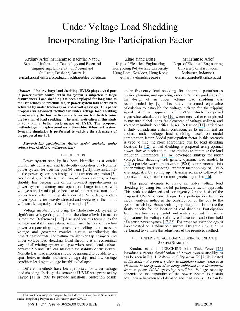
Kundur, et al in IEE/CIGRE Joint Task Force [23] introduce a recent classification of power system stability as can be seen in Fig. 1. Voltage stability as in [23] is delineated as the ability of a power system to maintain steady voltages at all buses in the system after being subjected to a disturbance from a given initial operating condition. Voltage stability depends on the capability of the power system to sustain equilibrium between load demand and load supply. As can be
This work was supported in part by an Indonesia Government Scholarship and a Hong Kong Polytechnic University grant (ZV3E)
978-1-4244-7398-4/10/$26.00 ©2010 IEEE 561 IPEC 2010
seen in Fig. 1, voltage stability can be clasubcategories: large-disturbance and small-disstability and it may be short-term or long-term
Figure 1. Power system stability classificat
The voltage stability evaluation for a givinspects two aspects, proximity that verifies hois operating from the voltage collapse pointthat identifies areas prone to voltage instaboffers solution information useful to forestal24].
When succession of the voltage instabilityin partial or total blackout or considerably loware below the tolerable limits in the majorsystem, the system is considered to be ccollapse is condition of heavily loaded electriwhich can lead to declining voltages, cascablackouts [25]. As transmission network becomvoltage instability/collapse risk also boosts utwo defense actions against incidents thainstability, as the power system become mwork closer to their limits [16]:
• preventively deed to observe the margin by taking into considecontingencies possibilities then performpreserve sufficient system margins.
• correctively deed to negate more utilizing automatic corrective approtection schemes.
Voltage instability is also believed as the cblackout in Canada and Northeast United Sta2003 [29, 30]. During this blackout, firstly, transmission lines tripped and resulted in one mbeing overload and then disconnection of anotFurthermore, the 138 kV transmission lines acascading failures continue causing the voltatripping of lines and generators in response to the system.
Power System
Stability
Rotor Angle Stability
Small-Disturbance
Angle Stability
Transient Stability
Frequency Stability
Voltage Stability
Large-Disturbance
Voltage Stability
Small-Disturbance
Voltage Stability
assified into two sturbance voltage incident.
tion [23]
ven system state ow far the system t and mechanism bility issues and ll instability [6,
y incidents results w voltages which rity areas of the collapse. Voltage ic power systems ading failure and me more stressed, up. Yet, there are at might initiate
more stressed and
system security eration different m right actions to
severe risks by pplications with
core cause of the ates at 14 August
several 345 kV more 345 kV line ther 345 kV line. also tripped. The age dropped and under voltage on
It is important for power systethis menace. Research has attested counter-measure action against voltaphilosophy of UVLS is that whenethen lead to voltage drop condition blevel for a certain pre-determined loads should be removed [26]. It ivoltage will retrieve to its normal loads. The objective of a UVLS reactive power within the system, toto manage the voltage problems rather than permitting it to spreadConsequently, the design of an UUVLS must cover enough loads as wTherefore, there are some consideload shedding [26, 28]:
A. Amount of load to be shed. Shedding adequate amount of lo
ensure UVLS can mitigate the meShedding insufficient amount of thebe effective in arresting voltage coshedding more load than requirefrequency circumstances. In the conscheme was examined by an elecwith these setting:
• Shedding 5% of load when10% below lowest normaltime delay.
• Shedding 5% of load when8% below lowest normal vdelay.
• Shedding 5% of load when tlowest normal voltage after
B. Location of load shedding Some considerations to determin
are proposed in [26]. Study in [11] sthe correct location can arrest voshedding the same amount of loaddifferent result and may not be effecstability.
C. Timing and time steps of load sLoad shedding is executed in ste
shedding condition. The minimum is triggered should be sufficient in pas well as avoiding unnecessary tripwhere load shedding is unnecessary.
D. Voltage level(s) at which sheddThe voltage level for load shedd
level that indicates the inception of above the voltage levels where mvoltage collapse is immensely quickcan be around 8-15% below lowest n
Many utilities have implementshedding programs. Reference [applications of UVLS in several cou
Short Term
Short Term
Short Term
Long Term
Short Term
Long Term
Short Term
Long Term
em engineers to understand that UVLS is an effectual
age instability/collapse. The ever the system is disrupted below a certain pre-selected time period, then selected
is expected that the system limit by cutting off some
is to reinstate the balance o avert voltage collapse and reside within a local area d out to other areas [27].
UVLS should be “robust”. well as not overly sensitive. erations to ensure efficient
oad is imperative in order to nace of voltage instability. e necessitated load will not ollapse, on the other hand, ed may lead to an over ncept of UVLS [8], a UVLS tric area utilities company
n the system voltage drops l voltage after 1.5 second
n the system voltage drops voltage after 3 second time
the voltage drops 8% below 6 second time delay.
ne location of load shedding shows that shedding load in ltage instability. However,
d in different location gives ctive to improve the system
shedding. eps in order to preclude over time delay before a UVLS preventing voltage collapse pping during transient time .
ding ding should be just above a f voltage collapse as well as motors begin to stall, since k after it. This voltage level normal voltage [8].
ted the under voltage load 31] summarizes different
untries.
562
III. PARTICIPATION FACTOR METHODOLOGY One important factor to be taken into account in designing
effective UVLS is location where the load should be shed. One possible approach for this matter is by analyzing the system stability separately where load shedding takes place at each different bus. This method may be suitable for small power system, nevertheless, for moderate or even large power system, this process will be time consuming. Bus participation factor in modal analysis, on the other hand, offers effective solution for this problem. The concept modal analysis can be found in [24]. This technique provides useful information about voltage stability critical areas and information about the best steps to enhance system stability.
Power system is modeled as follow, ∆∆ ∆∆ ∆∆ ∆∆ (1)
where, ∆ is variations in bus real power ∆ is variations in bus reactive power injection ∆ is variations in bus voltage angle ∆ is variations in bus voltage magnitude J is the Jacobian matrix of partial derivatives
Critical bus recognition is accomplished by applying modal analysis method on the system Jacobian matrix, hence (2)
Where, JR is the reduced Jacobian matrix. The modes of power network can be acquired by the eigenvalues and eigenvectors of the reduced Jacobian matrix JR, thus Λ (3)
0 00 000 0 0
(4) Where,
is the right eigenvector matrix of JR is the left eigenvector matrix of JR Λ is the diagonal eigenvector matrix of JR
The relative bus participation factor of the kth bus to the ith mode is provided by the left and right eigenvectors correlating to the system critical modes and can be given as, (5)
Load buses with large participation factor have more influence in contributing to the voltage instability. Consequently these buses become the best candidate buses for determining the location of load shedding to enhance system voltage stability.
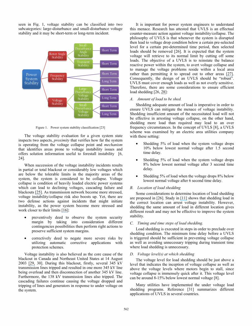
IV. TEST RESULTS AND ANALYSIS A 9-bus test system shown in Fig. 2 is used in this
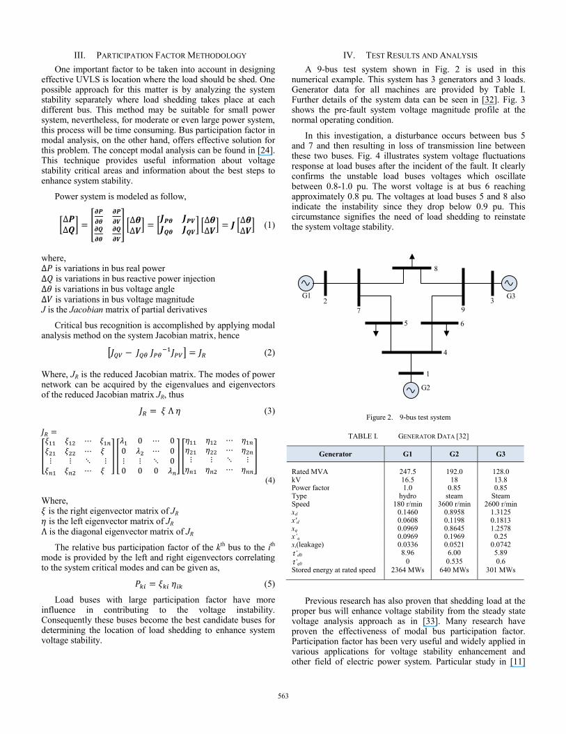
numerical example. This system has 3 generators and 3 loads. Generator data for all machines are provided by Table I. Further details of the system data can be seen in [32]. Fig. 3 shows the pre-fault system voltage magnitude profile at the normal operating condition.
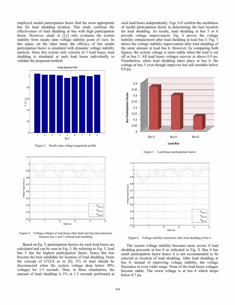
In this investigation, a disturbance occurs between bus 5 and 7 and then resulting in loss of transmission line between these two buses. Fig. 4 illustrates system voltage fluctuations response at load buses after the incident of the fault. It clearly confirms the unstable load buses voltages which oscillate between 0.8-1.0 pu. The worst voltage is at bus 6 reaching approximately 0.8 pu. The voltages at load buses 5 and 8 also indicate the instability since they drop below 0.9 pu. This circumstance signifies the need of load shedding to reinstate the system voltage stability.
Figure 2. 9-bus test system
TABLE I. GENERATOR DATA [32]
Generator G1 G2 G3
Rated MVA 247.5 192.0 128.0 kV 16.5 18 13.8Power factor 1.0 0.85 0.85Type hydro steam SteamSpeed 180 r/min 3600 r/min 2600 r/minxd 0.1460 0.8958 1.3125x'd 0.0608 0.1198 0.1813xq 0.0969 0.8645 1.2578x’q 0.0969 0.1969 0.25xl(leakage) 0.0336 0.0521 0.0742τ’d0 8.96 6.00 5.89τ’q0 0 0.535 0.6Stored energy at rated speed 2364 MWs 640 MWs 301 MWs
Previous research has also proven that shedding load at the proper bus will enhance voltage stability from the steady state voltage analysis approach as in [33]. Many research have proven the effectiveness of modal bus participation factor. Participation factor has been very useful and widely applied in various applications for voltage stability enhancement and other field of electric power system. Particular study in [11]
1
2 3
4
5 6
7
8
9
G1
G2
G3
563
employed modal participation factor find the bus for load shedding location. This studeffectiveness of load shedding at bus with hfactor. However, study in [11] only evalustability from steady state voltage stability pthis paper, on the other hand, the efficacyparticipation factor is simulated with dynamicanalysis. Since this system only consists of 3 shedding is simulated at each load buses validate the proposed method.
1 2 3 4 5 6 70
0.2
0.4
0.6
0.8
1
V [
p.u.
]
Voltage Magnitude Profile
Bus #
Figure 3. Steady state voltage magnitude
0 1 2 30.2
0.3
0.4
0.5
0.6
0.7
0.8
0.9
1
1.1
time (s)
Vol
tage
mag
nitu
de (
pu)
Figure 4. Voltage collapse at load buses after fault andbetween bus 5 and 7 without load shedd
Based on Eq. 5, participation factors for eacalculated and can be seen in Fig. 5. By referribus 5 has the highest participation factor, become the best candidate for location of loadthe concept of UVLS as in [8], 5% of disconnected when the system voltage drvoltages for 1.5 seconds. Thus, in these amount of load shedding is 5% at 1.5 secon
most appropriate dy confirms the high participation uates the system point of view. In y of bus modal c voltage stability
load buses, load individually to
8 9
profile
4 5
VBus 5
VBus 6
VBus 8
d line disconnection ding
ach load buses are ing to Fig. 5, load
hence this bus d shedding. From
load should be rop below 90% simulations, the
nds performed at
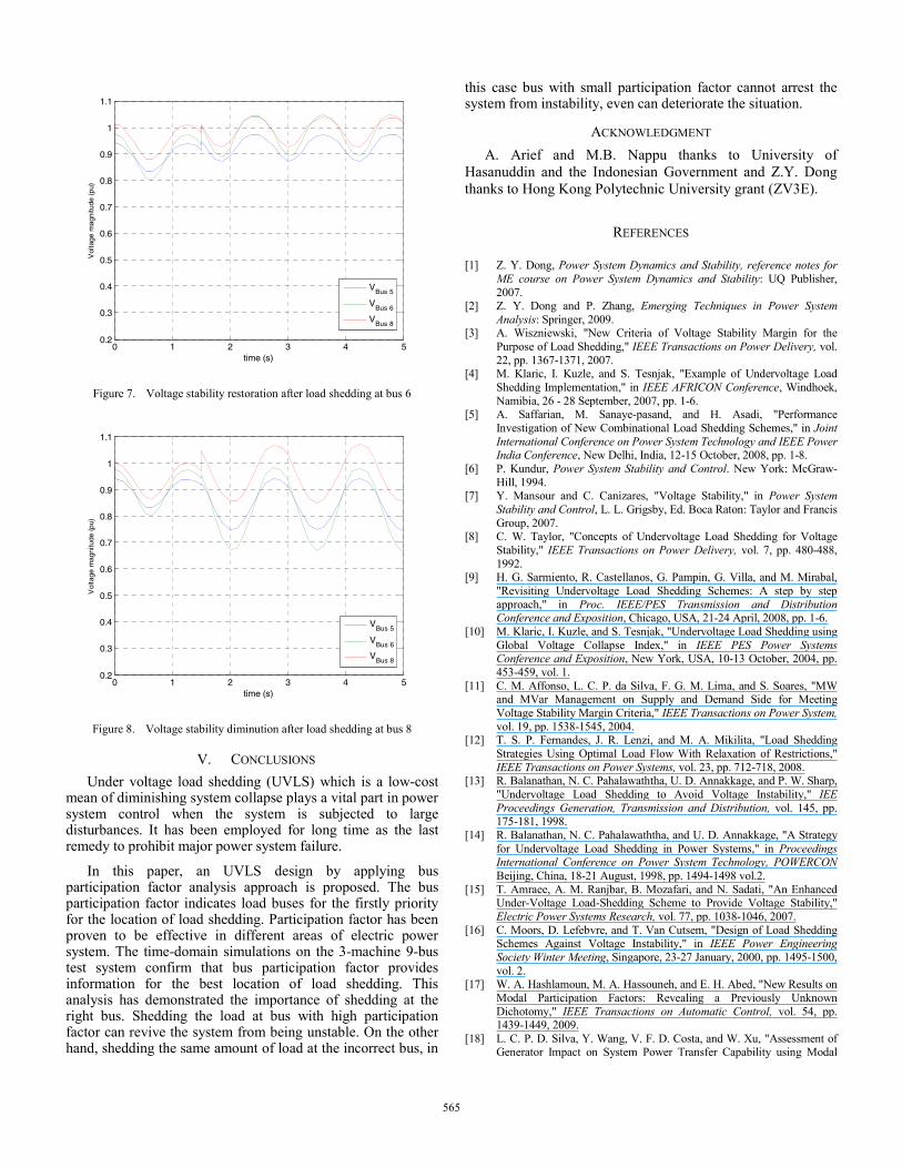
each load buses independently. Figsof modal participation factor in defor load shedding. As results, loaprovide voltage improvement. Fistability enhancement after load sheshows the voltage stability improvethe same amount at load bus 6. Hofigures, the system voltage is more off at bus 5. All load buses voltageNonetheless, when load shedding voltage at bus 5 even though impro0.9 pu.
Figure 5. Load buses par
0 1 20.2
0.3
0.4
0.5
0.6
0.7
0.8
0.9
1
1.1
time (s)
Vol
tage
mag
nitu
de (
pu)
Figure 6. Voltage stability restoration
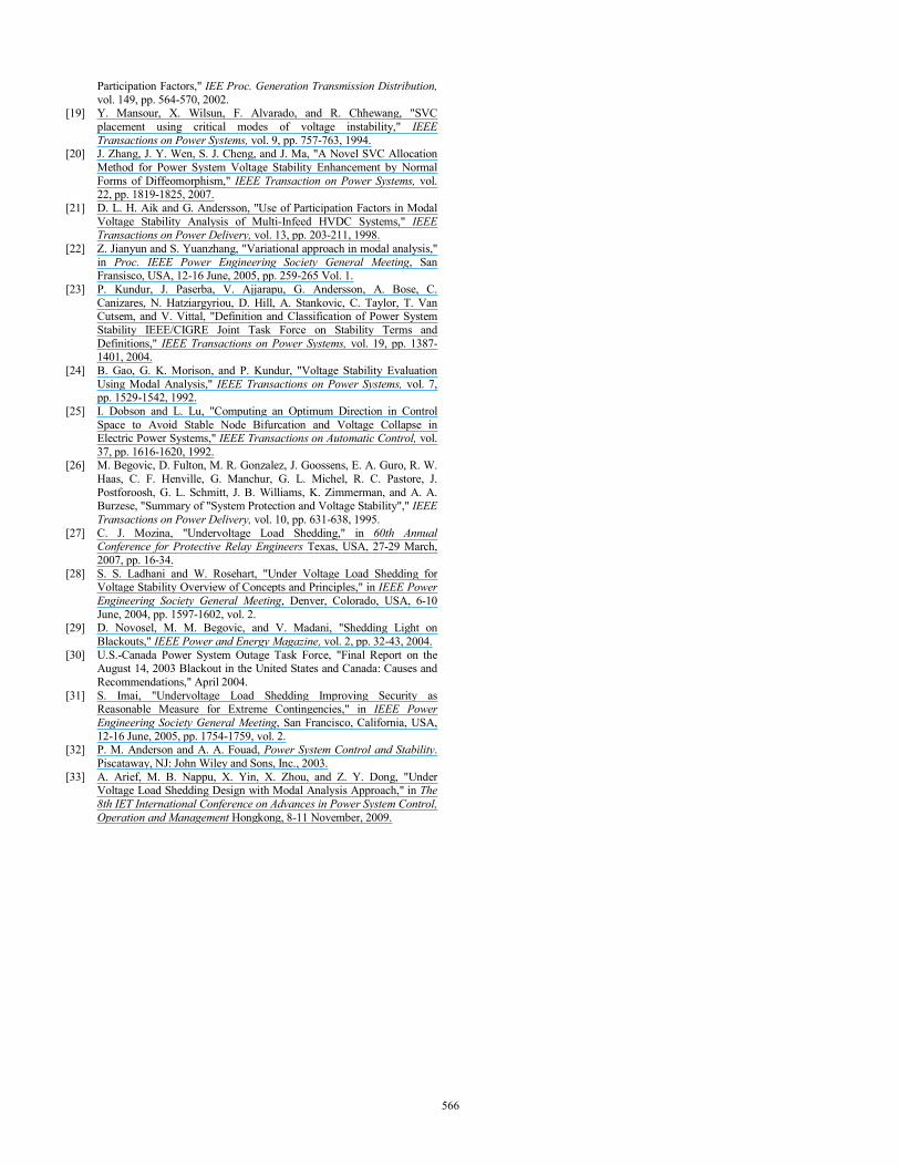
The system voltage stability beshedding proceeds at bus 8 as indismall participation factor hence it selected as location of load sheddibus 8, instead of improving voltfluctuates in even wider range. Nonbecome stable. The worst voltagebelow 0.7 pu.
0
0.05
0.1
0.15
0.2
0.25
0.3
0.35
0.4
Bus 5 Bus 6
Bus
Part
icip
atio
n Fa
ctor
Load B
. 6-8 confirm the usefulness termining the best location
ad shedding at bus 5 or 6 ig. 6 proves the voltage edding at load bus 5. Fig. 7 ment after load shedding of owever, by comparing both stable when the load is cut
es recover to above 0.9 pu. takes place at bus 6, the
ves but still unstable below
rticipation factor
3 4 5
VBus 5
VBus 6
VBus 8
n after load shedding at bus 5
ecomes more severe if load icated in Fig. 8. Bus 8 has is not recommended to be
ing. After load shedding at tage stability, the voltage
ne of the load buses voltages e is at bus 6 which drops
6 Bus 8
Bus
564
0 1 2 3 4 50.2
0.3
0.4
0.5
0.6
0.7
0.8
0.9
1
1.1
time (s)
Vol
tage
mag
nitu
de (
pu)
VBus 5
VBus 6
VBus 8
Figure 7. Voltage stability restoration after load shedding at bus 6
0 1 2 3 4 50.2
0.3
0.4
0.5
0.6
0.7
0.8
0.9
1
1.1
time (s)
Vol
tage
mag
nitu
de (
pu)
VBus 5
VBus 6
VBus 8
Figure 8. Voltage stability diminution after load shedding at bus 8
V. CONCLUSIONS Under voltage load shedding (UVLS) which is a low-cost
mean of diminishing system collapse plays a vital part in power system control when the system is subjected to large disturbances. It has been employed for long time as the last remedy to prohibit major power system failure.
In this paper, an UVLS design by applying bus participation factor analysis approach is proposed. The bus participation factor indicates load buses for the firstly priority for the location of load shedding. Participation factor has been proven to be effective in different areas of electric power system. The time-domain simulations on the 3-machine 9-bus test system confirm that bus participation factor provides information for the best location of load shedding. This analysis has demonstrated the importance of shedding at the right bus. Shedding the load at bus with high participation factor can revive the system from being unstable. On the other hand, shedding the same amount of load at the incorrect bus, in
this case bus with small participation factor cannot arrest the system from instability, even can deteriorate the situation.
ACKNOWLEDGMENT A. Arief and M.B. Nappu thanks to University of
Hasanuddin and the Indonesian Government and Z.Y. Dong thanks to Hong Kong Polytechnic University grant (ZV3E).
REFERENCES
[1] Z. Y. Dong, Power System Dynamics and Stability, reference notes for ME course on Power System Dynamics and Stability: UQ Publisher, 2007.
[2] Z. Y. Dong and P. Zhang, Emerging Techniques in Power System Analysis: Springer, 2009.
[3] A. Wiszniewski, "New Criteria of Voltage Stability Margin for the Purpose of Load Shedding," IEEE Transactions on Power Delivery, vol. 22, pp. 1367-1371, 2007.
[4] M. Klaric, I. Kuzle, and S. Tesnjak, "Example of Undervoltage Load Shedding Implementation," in IEEE AFRICON Conference, Windhoek, Namibia, 26 - 28 September, 2007, pp. 1-6.
[5] A. Saffarian, M. Sanaye-pasand, and H. Asadi, "Performance Investigation of New Combinational Load Shedding Schemes," in Joint International Conference on Power System Technology and IEEE Power India Conference, New Delhi, India, 12-15 October, 2008, pp. 1-8.
[6] P. Kundur, Power System Stability and Control. New York: McGraw-Hill, 1994.
[7] Y. Mansour and C. Canizares, "Voltage Stability," in Power System Stability and Control, L. L. Grigsby, Ed. Boca Raton: Taylor and Francis Group, 2007.
[8] C. W. Taylor, "Concepts of Undervoltage Load Shedding for Voltage Stability," IEEE Transactions on Power Delivery, vol. 7, pp. 480-488, 1992.
[9] H. G. Sarmiento, R. Castellanos, G. Pampin, G. Villa, and M. Mirabal, "Revisiting Undervoltage Load Shedding Schemes: A step by step approach," in Proc. IEEE/PES Transmission and Distribution Conference and Exposition, Chicago, USA, 21-24 April, 2008, pp. 1-6.
[10] M. Klaric, I. Kuzle, and S. Tesnjak, "Undervoltage Load Shedding using Global Voltage Collapse Index," in IEEE PES Power Systems Conference and Exposition, New York, USA, 10-13 October, 2004, pp. 453-459, vol. 1.
[11] C. M. Affonso, L. C. P. da Silva, F. G. M. Lima, and S. Soares, "MW and MVar Management on Supply and Demand Side for Meeting Voltage Stability Margin Criteria," IEEE Transactions on Power System, vol. 19, pp. 1538-1545, 2004.
[12] T. S. P. Fernandes, J. R. Lenzi, and M. A. Mikilita, "Load Shedding Strategies Using Optimal Load Flow With Relaxation of Restrictions," IEEE Transactions on Power Systems, vol. 23, pp. 712-718, 2008.
[13] R. Balanathan, N. C. Pahalawaththa, U. D. Annakkage, and P. W. Sharp, "Undervoltage Load Shedding to Avoid Voltage Instability," IEE Proceedings Generation, Transmission and Distribution, vol. 145, pp. 175-181, 1998.
[14] R. Balanathan, N. C. Pahalawaththa, and U. D. Annakkage, "A Strategy for Undervoltage Load Shedding in Power Systems," in Proceedings International Conference on Power System Technology, POWERCON Beijing, China, 18-21 August, 1998, pp. 1494-1498 vol.2.
[15] T. Amraee, A. M. Ranjbar, B. Mozafari, and N. Sadati, "An Enhanced Under-Voltage Load-Shedding Scheme to Provide Voltage Stability," Electric Power Systems Research, vol. 77, pp. 1038-1046, 2007.
[16] C. Moors, D. Lefebvre, and T. Van Cutsem, "Design of Load Shedding Schemes Against Voltage Instability," in IEEE Power Engineering Society Winter Meeting, Singapore, 23-27 January, 2000, pp. 1495-1500, vol. 2.
[17] W. A. Hashlamoun, M. A. Hassouneh, and E. H. Abed, "New Results on Modal Participation Factors: Revealing a Previously Unknown Dichotomy," IEEE Transactions on Automatic Control, vol. 54, pp. 1439-1449, 2009.
[18] L. C. P. D. Silva, Y. Wang, V. F. D. Costa, and W. Xu, "Assessment of Generator Impact on System Power Transfer Capability using Modal
565
Participation Factors," IEE Proc. Generation Transmission Distribution, vol. 149, pp. 564-570, 2002.
[19] Y. Mansour, X. Wilsun, F. Alvarado, and R. Chhewang, "SVC placement using critical modes of voltage instability," IEEE Transactions on Power Systems, vol. 9, pp. 757-763, 1994.
[20] J. Zhang, J. Y. Wen, S. J. Cheng, and J. Ma, "A Novel SVC Allocation Method for Power System Voltage Stability Enhancement by Normal Forms of Diffeomorphism," IEEE Transaction on Power Systems, vol. 22, pp. 1819-1825, 2007.
[21] D. L. H. Aik and G. Andersson, "Use of Participation Factors in Modal Voltage Stability Analysis of Multi-Infeed HVDC Systems," IEEE Transactions on Power Delivery, vol. 13, pp. 203-211, 1998.
[22] Z. Jianyun and S. Yuanzhang, "Variational approach in modal analysis," in Proc. IEEE Power Engineering Society General Meeting, San Fransisco, USA, 12-16 June, 2005, pp. 259-265 Vol. 1.
[23] P. Kundur, J. Paserba, V. Ajjarapu, G. Andersson, A. Bose, C. Canizares, N. Hatziargyriou, D. Hill, A. Stankovic, C. Taylor, T. Van Cutsem, and V. Vittal, "Definition and Classification of Power System Stability IEEE/CIGRE Joint Task Force on Stability Terms and Definitions," IEEE Transactions on Power Systems, vol. 19, pp. 1387-1401, 2004.
[24] B. Gao, G. K. Morison, and P. Kundur, "Voltage Stability Evaluation Using Modal Analysis," IEEE Transactions on Power Systems, vol. 7, pp. 1529-1542, 1992.
[25] I. Dobson and L. Lu, "Computing an Optimum Direction in Control Space to Avoid Stable Node Bifurcation and Voltage Collapse in Electric Power Systems," IEEE Transactions on Automatic Control, vol. 37, pp. 1616-1620, 1992.
[26] M. Begovic, D. Fulton, M. R. Gonzalez, J. Goossens, E. A. Guro, R. W. Haas, C. F. Henville, G. Manchur, G. L. Michel, R. C. Pastore, J. Postforoosh, G. L. Schmitt, J. B. Williams, K. Zimmerman, and A. A. Burzese, "Summary of "System Protection and Voltage Stability"," IEEE Transactions on Power Delivery, vol. 10, pp. 631-638, 1995.
[27] C. J. Mozina, "Undervoltage Load Shedding," in 60th Annual Conference for Protective Relay Engineers Texas, USA, 27-29 March, 2007, pp. 16-34.
[28] S. S. Ladhani and W. Rosehart, "Under Voltage Load Shedding for Voltage Stability Overview of Concepts and Principles," in IEEE Power Engineering Society General Meeting, Denver, Colorado, USA, 6-10 June, 2004, pp. 1597-1602, vol. 2.
[29] D. Novosel, M. M. Begovic, and V. Madani, "Shedding Light on Blackouts," IEEE Power and Energy Magazine, vol. 2, pp. 32-43, 2004.
[30] U.S.-Canada Power System Outage Task Force, "Final Report on the August 14, 2003 Blackout in the United States and Canada: Causes and Recommendations," April 2004.
[31] S. Imai, "Undervoltage Load Shedding Improving Security as Reasonable Measure for Extreme Contingencies," in IEEE Power Engineering Society General Meeting, San Francisco, California, USA, 12-16 June, 2005, pp. 1754-1759, vol. 2.
[32] P. M. Anderson and A. A. Fouad, Power System Control and Stability. Piscataway, NJ: John Wiley and Sons, Inc., 2003.
[33] A. Arief, M. B. Nappu, X. Yin, X. Zhou, and Z. Y. Dong, "Under Voltage Load Shedding Design with Modal Analysis Approach," in The 8th IET International Conference on Advances in Power System Control, Operation and Management Hongkong, 8-11 November, 2009.
566
Related Documents