5995504544 January 2008 Under the Counter Ice Maker Service Manual Models: EI15IM55GS, E15IM60GSS, and E15IM60GPS

Welcome message from author
This document is posted to help you gain knowledge. Please leave a comment to let me know what you think about it! Share it to your friends and learn new things together.
Transcript

5995504544 January 2008
Under the Counter Ice Maker Service Manual
Models: EI15IM55GS, E15IM60GSS, and E15IM60GPS

2
ATTENTION!!!This service manual is intended for use by persons having electrical and mechnicaltraining and a level of knowledge of these subjects generally considered acceptable in theappliance repair trade. Electrolux Home Products cannot be responsible, nor assume anyliability, for injury or damage of any kind arising from the use of this manual.
© 2007 Electrolux Home Products, Inc.
SAFE SERVICING PRACTICES - ALL APPLIANCES
To avoid personal injury and/or property damage, it is important that Safe ServicingPractices be observed. The following are some limited examples of safe practices:
1. DO NOT attempt a product repair if you have any doubts as to your ability tocomplete it in a safe and satisfactory manner.
2. Before servicing or moving an appliance:
• Remove the power cord from the electrical outlet, trip the circuit breaker to theOFF position, or remove the fuse.
• Turn off the gas supply.• Turn off the water supply.
3. Never interfere with the proper operation of any safety device.
4. USE ONLY REPLACEMENT PARTS CATALOGED FOR THIS APPLIANCE.SUBSTITUTIONS MAY DEFEAT COMPLIANCE WITH SAFETYSTANDARDS SET FOR HOME APPLIANCES.
5. GROUNDING: The standard color coding for safety ground wires is GREEN, orGREEN with YELLOW STRIPES. Ground leads are not to be used as currentcarrying conductors. It is EXTREMELY important that the service technicianreestablish all safety grounds prior to completion of service. Failure to do so willcreate a hazard.
6. Prior to returning the product to service, ensure that:
• All electrical connections are correct and secure• All electrical leads are properly dressed and secured away from sharp edges,
high-temperature components, and moving parts• All non-insulated electrical terminals, connectors, heaters, etc. are adequately
spaced away from all metal parts and panels• All safety grounds (both internal and external) are correctly and securely
connected• All panels are properly and securely reassembled
Safe Servicing Practices
3Table of Contents
Safe Servicing Practices - All Appliances........................2
InstallationLeveling ..................................................................................4Adjusting Door ........................................................................4
Checking Door Alignment ....................................................4Adjusting Door Alignment ....................................................5
General InstructionsKeypad Options .......................................................................6
ON/OFF .................................................................................6Showroom Mode ..................................................................6Service Mode .......................................................................7Blackout / Sabbath Mode......................................................7Clean Cycle ...........................................................................7Force Harvest .......................................................................7Forced Defrost ......................................................................7Ice Thickness Adjust.............................................................7Temporary Shutdown / Office Mode .....................................7Relay Status .........................................................................7
Service InformationService Menu ..........................................................................8Error Codes .............................................................................8Board Components .................................................................9Electronic Control Quick Guide .............................................10Keypad Options .....................................................................11
ON/OFF ...............................................................................11Viewing Actual Temperature ...............................................11Changing From Fahrenheit to Celsius .................................11Showroom Mode ................................................................11Service Mode .....................................................................11Blackout / Sabbath Mode....................................................12Model Number Change .......................................................12
Service Menu ........................................................................12Error Codes ...........................................................................13Electronic Control Quick Guide .............................................13Thermister Types ..................................................................14Refrigeration System Diagnosis Guide .................................14Filter Drier Installation ..........................................................15Evacuating and Recharging ..................................................15
Equipment Needed .............................................................16Installing Equipment Needed ..............................................16Evacuating System .............................................................16
Charging the System ............................................................17Preparing the Cyclinder ......................................................17
Final Leak Test ......................................................................17Evacuating and Recharging Connections ..............................18Verify Refrigerant Type in System .........................................19R-134a Refrigeration Systems ..............................................19Miscibility of R-134a and Ester Oil ........................................19Water in the Refrigeration System ........................................20Vacuum Pump Maintenance .................................................20Refrigerant Leaks ..................................................................21
Leak Detection ....................................................................21HFC-124a, CFC-12 Pressure Temperature Chart ...................22Inhalation Toxicity .................................................................23Cardiac Sensitization .............................................................23
Table of contentsSpills and leaks .....................................................................23Skin and Eye Contact ............................................................23Combustibility of HFC-134a ..................................................24
Leak Testing .......................................................................24Bulk Delivery and Storage ..................................................24Filling and Charging Operations..........................................24Refrigerant Recovery Systems ..........................................24
Thermal Decomposition ........................................................24Ice Cube Thickness Adjustment ............................................25
Interval - As Required .........................................................25Operating Environments/Climate Control Requirements .......26Model EI151M55GS ..............................................................26
Defrost Information ............................................................26Compressor / Coil Specifications........................................26Operation ............................................................................27Thermister Outage ..............................................................28
Service ..................................................................................28Troubleshooting ....................................................................28
Display shows ER or P1 .....................................................28No ice .................................................................................28Too much ice ......................................................................28Too little ice ........................................................................29Ice not sized to customer satisfaction ................................29Noise ..................................................................................29No water in trough..............................................................29Ice does not release from evaporator .................................29Poor ice quality...................................................................29Water in ice bin ..................................................................29Display showing something other than “ice” .....................29Display showing random snaking of characters .................29Display not illuminating but unit operating .........................29Unit is not operating - no cooling - no fans ........................29
Wiring Diagram .....................................................................30Ice Production Rates ............................................................30Prepare Plumbing .................................................................31
Gravity Drain ......................................................................31Factory Installed Drain Pump .............................................31Locally Installed Drain Pump ..............................................33U-CLR Drain Kit (Available for purchase) ...........................33
Self-Cleaning Cycle Instructions ...........................................36Interior Storage Bin Cleaning ................................................36
Parts InformationEI151M55GS Parts Section ..................................................37
Customer Call GuideConcern / Response ..............................................................45
4 Installation
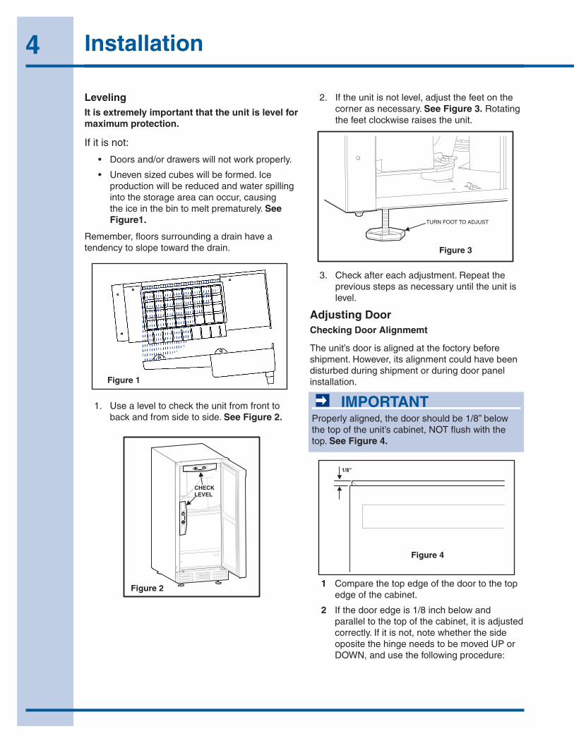
LevelingIt is extremely important that the unit is level for maximum protection.
If it is not:
• Doorsand/ordrawerswillnotworkproperly.
• Unevensizedcubeswillbeformed.Iceproductionwillbereducedandwaterspillingintothestorageareacanoccur,causingtheiceinthebintomeltprematurely.See Figure1.
Remember,floorssurroundingadrainhaveatendencytoslopetowardthedrain.
IMPORTANTProperlyaligned,thedoorshouldbe1/8”belowthetopoftheunit’scabinet,NOTflushwiththetop.See Figure 4.
Adjusting DoorChecking Door Alignmemt
Theunit’sdoorisalignedatthefoctorybeforeshipment.However,itsalignmentcouldhavebeendisturbedduringshipmentorduringdoorpanelinstallation.
1 Comparethetopedgeofthedoortothetopedgeofthecabinet.
2 Ifthedooredgeis1/8inchbelowandparalleltothetopofthecabinet,itisadjustedcorrectly.Ifitisnot,notewhetherthesideopositethehingeneedstobemovedUPorDOWN,andusethefollowingprocedure:
1. Usealeveltochecktheunitfromfronttobackandfromsidetoside.See Figure 2.
Figure 1
CHECKLEVEL
Figure 2
TURN FOOT TO ADJUST
Figure 3
2. Iftheunitisnotlevel,adjustthefeetonthecornerasnecessary.See Figure 3.Rotatingthefeetclockwiseraisestheunit.
3. Checkaftereachadjustment.Repeatthepreviousstepsasnecessaryuntiltheunitislevel.
1/8”
Figure 4
5Installation
13
Checking Door Alignment - Échelon ModelsThe unit’s door is aligned at the factory before shipment. However, its alignment could have been disturbed during shipment or during door panel installation.
IMPORTANTIMPORTANT
Properly aligned, the door should be 1/8" below the top of the unit’s cabinet, NOT flush with the top (Figure 5).
Figure 5
1. Compare the top edge of the door to the top edge of the cabinet.
2. If the door edge is 1/8" below and parallel to the top of the cabinet, it is adjusted correctly. If it is not, note whether the side opposite the hinge needs to be moved UP or DOWN, and use the following procedure.
Échelon Full Overlay
NOTE: If door is adjusted correctly, but panel is not square with the adjacent cabinets, slight adjustments can be made by drilling the holes in the vinyl-coated steel panel slightly oversized (Figure 6).
Figure 6
Adjusting Door Alignment
1. Remove top hinge screw pin using a Phillips screwdriver (Figure 7). Remove door by tilting forward and lifting off bottom hinge pin.
Figure 7
2. With door upside-down, loosen but do not remove the two screws on the door’s bottom hinge plate.
6 Adjust Door
1/8"
ULIN_0295_A
Drill 5/32" x 3/8" Deep for usewith #10 x 5/8" Wood Screwand Nylon Spacer – 6 Places
1"±1/8"
1"±1/32"1"±1/32"
14-5/16"±1/4"
27"±1/4"
Rear Viewof
Wood Panel
ULIN_0310_A
ULIN_0133_A
Figure 5
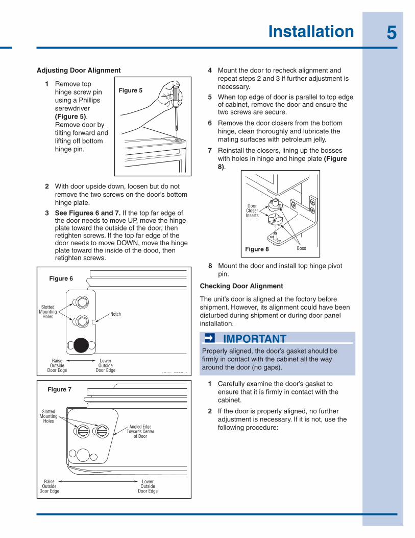
2 Withdoorupsidedown,loosenbutdonotremovethetwoscrewsonthedoor’sbottomhingeplate.
3 See Figures 6 and 7.IfthetopfaredgeofthedoorneedstomoveUP,movethehingeplatetowardtheoutsideofthedoor,thenretightenscrews.IfthetopfaredgeofthedoorneedstomoveDOWN,movethehingeplatetowardtheinsideofthedood,thenretightenscrews.
14
Figure 8
3. See Figure 8 and Figure 9. If the top far edge of the door needs to move UP, move the hinge plate toward the outside of the door and retighten screws. If the top far edge of the door needs to move DOWN, move the hinge plate toward the inside of the door and retighten screws.
Figure 9
4. Mount the door to recheck alignment and repeat steps 2 and 3 if further adjustment is necessary.
5. When top edge of door is parallel to top edge of cabinet, remove the door and ensure the two screws are secure.
6. Remove the door closers from the bottom hinge, clean thoroughly and lubricate the mating surfaces with petroleum jelly.
7. Reinstall the closers, lining up the bosses with holes in hinge and hinge plate (Figure 10).
Figure 10
8. Mount the door, install top hinge pivot pin.
Checking Door Alignment -Origins ModelsThe unit’s door is aligned at the factory before shipment. However, its alignment could have been disturbed during shipment or during door panel installation.
IMPORTANTIMPORTANT
Properly aligned, the door’s gasket should be firmly in contact with the cabinet all the way around the door (no gaps).
1. Carefully examine the door’s gasket to assure that it is firmly in contact with the cabinet.
2. If the door is properly aligned, no further adjustment is necessary. If it is not, use the following procedure.
NotchSlotted
MountingHoles
RaiseOutside
Door Edge
LowerOutside
Door EdgeULIN_0297_A
Angled EdgeTowards Center
of Door
SlottedMounting
Holes
RaiseOutside
Door Edge
LowerOutside
Door Edge
ULIN_0311_A
2115WC, 2115WCOL, 2175WC, 2175WCOL Only
Door Closer Inserts
Boss
ULIN_0298a_A
Figure 6
Adjusting Door Alignment
14
Figure 8
3. See Figure 8 and Figure 9. If the top far edge of the door needs to move UP, move the hinge plate toward the outside of the door and retighten screws. If the top far edge of the door needs to move DOWN, move the hinge plate toward the inside of the door and retighten screws.
Figure 9
4. Mount the door to recheck alignment and repeat steps 2 and 3 if further adjustment is necessary.
5. When top edge of door is parallel to top edge of cabinet, remove the door and ensure the two screws are secure.
6. Remove the door closers from the bottom hinge, clean thoroughly and lubricate the mating surfaces with petroleum jelly.
7. Reinstall the closers, lining up the bosses with holes in hinge and hinge plate (Figure 10).
Figure 10
8. Mount the door, install top hinge pivot pin.
Checking Door Alignment -Origins ModelsThe unit’s door is aligned at the factory before shipment. However, its alignment could have been disturbed during shipment or during door panel installation.
IMPORTANTIMPORTANT
Properly aligned, the door’s gasket should be firmly in contact with the cabinet all the way around the door (no gaps).
1. Carefully examine the door’s gasket to assure that it is firmly in contact with the cabinet.
2. If the door is properly aligned, no further adjustment is necessary. If it is not, use the following procedure.
NotchSlotted
MountingHoles
RaiseOutside
Door Edge
LowerOutside
Door EdgeULIN_0297_A
Angled EdgeTowards Center
of Door
SlottedMounting
Holes
RaiseOutside
Door Edge
LowerOutside
Door Edge
ULIN_0311_A
2115WC, 2115WCOL, 2175WC, 2175WCOL Only
Door Closer Inserts
Boss
ULIN_0298a_A
Figure 7
1 RemovetophingescrewpinusingaPhillipsserewdriver(Figure 5).Removedoorbytiltingforwardandliftingoffbottomhingepin.
4 Mountthedoortorecheckalignmentandrepeatsteps2and3iffurtheradjustmentisnecessary.
5 Whentopedgeofdoorisparalleltotopedgeofcabinet,removethedoorandensurethetwoscrewsaresecure.
6 Removethedoorclosersfromthebottomhinge,cleanthoroughlyandlubricatethematingsurfaceswithpetroleumjelly.
7 Reinstalltheclosers,liningupthebosseswithholesinhingeandhingeplate(Figure 8).
14
Figure 8
3. See Figure 8 and Figure 9. If the top far edge of the door needs to move UP, move the hinge plate toward the outside of the door and retighten screws. If the top far edge of the door needs to move DOWN, move the hinge plate toward the inside of the door and retighten screws.
Figure 9
4. Mount the door to recheck alignment and repeat steps 2 and 3 if further adjustment is necessary.
5. When top edge of door is parallel to top edge of cabinet, remove the door and ensure the two screws are secure.
6. Remove the door closers from the bottom hinge, clean thoroughly and lubricate the mating surfaces with petroleum jelly.
7. Reinstall the closers, lining up the bosses with holes in hinge and hinge plate (Figure 10).
Figure 10
8. Mount the door, install top hinge pivot pin.
Checking Door Alignment -Origins ModelsThe unit’s door is aligned at the factory before shipment. However, its alignment could have been disturbed during shipment or during door panel installation.
IMPORTANTIMPORTANT
Properly aligned, the door’s gasket should be firmly in contact with the cabinet all the way around the door (no gaps).
1. Carefully examine the door’s gasket to assure that it is firmly in contact with the cabinet.
2. If the door is properly aligned, no further adjustment is necessary. If it is not, use the following procedure.
NotchSlotted
MountingHoles
RaiseOutside
Door Edge
LowerOutside
Door EdgeULIN_0297_A
Angled EdgeTowards Center
of Door
SlottedMounting
Holes
RaiseOutside
Door Edge
LowerOutside
Door Edge
ULIN_0311_A
2115WC, 2115WCOL, 2175WC, 2175WCOL Only
Door Closer Inserts
Boss
ULIN_0298a_AFigure 8
8 Mountthedoorandinstalltophingepivotpin.
Checking Door Alignment
Theunit’sdoorisalignedatthefoctorybeforeshipment.However,itsalignmentcouldhavebeendisturbedduringshipmentorduringdoorpanelinstallation.
IMPORTANTProperlyaligned,thedoor’sgasketshouldbefirmlyincontactwiththecabinetallthewayaroundthedoor(nogaps).
1 Carefullyexaminethedoor’sgaskettoensurethatitisfirmlyincontactwiththecabinet.
2 Ifthedoorisproperlyaligned,nofurtheradjustmentisnecessary.Ifitisnot,usethefollowingprocedure:
6 Installation / General Instructions
Adjusting Door Alignment
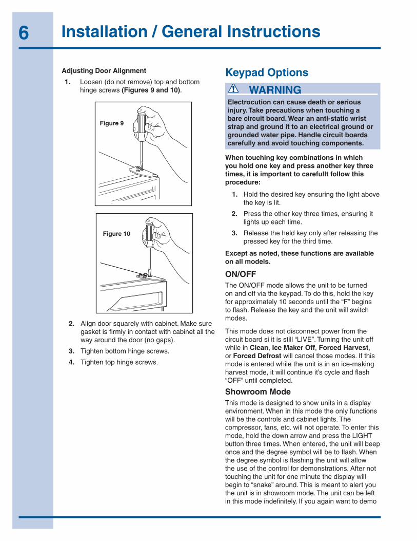
1. Loosen(donotremove)topandbottomhingescrews(Figures 9 and 10).
15
Adjusting Door Alignment1. Loosen (do not remove) top and bottom hinge screws
(Figure 11 and Figure 12).
Figure 11
Figure 12
2. Align door squarely with cabinet. Make sure gasket is firmly in contact with cabinet all the way around the door (no gaps).
3. Tighten bottom hinge screws.
4. Tighten top hinge screws.
Checking Drawer AlignmentThe unit’s drawers are aligned at the factory before shipment. However, their alignment could have been disturbed during shipment or during overlay panel installation.
Figure 13
See Figure 13. Check each drawer to confirm that it is aligned:
• Side-to-Side — When viewed from the top, the drawer front should be square with the sides of the cabinet.
• Front-to-Back — When viewed from the side, the drawer front should be straight with the cabinet’s sides, not cocked forward or back.
• Top-to-Bottom — When viewed from the front, the drawer should be level horizontally.
If both drawers are properly aligned, no further adjustment is necessary. If either drawer is not aligned, carefully follow instructions to remove that drawer, make the necessary adjustment and re-install the drawer.
ULIN_0293_A
ULIN_0104_A
7 Adjust Drawer
AlignedSide-to-Side
AlignedFront-to-Back
AlignedTop-to-Bottom ULIN_0312_A
Figure 9
15
Adjusting Door Alignment1. Loosen (do not remove) top and bottom hinge screws
(Figure 11 and Figure 12).
Figure 11
Figure 12
2. Align door squarely with cabinet. Make sure gasket is firmly in contact with cabinet all the way around the door (no gaps).
3. Tighten bottom hinge screws.
4. Tighten top hinge screws.
Checking Drawer AlignmentThe unit’s drawers are aligned at the factory before shipment. However, their alignment could have been disturbed during shipment or during overlay panel installation.
Figure 13
See Figure 13. Check each drawer to confirm that it is aligned:
• Side-to-Side — When viewed from the top, the drawer front should be square with the sides of the cabinet.
• Front-to-Back — When viewed from the side, the drawer front should be straight with the cabinet’s sides, not cocked forward or back.
• Top-to-Bottom — When viewed from the front, the drawer should be level horizontally.
If both drawers are properly aligned, no further adjustment is necessary. If either drawer is not aligned, carefully follow instructions to remove that drawer, make the necessary adjustment and re-install the drawer.
ULIN_0293_A
ULIN_0104_A
7 Adjust Drawer
AlignedSide-to-Side
AlignedFront-to-Back
AlignedTop-to-Bottom ULIN_0312_A
Figure 10
2. Aligndoorsquarelywithcabinet.Makesuregasketisfirmlyincontactwithcabinetallthewayaroundthedoor(nogaps).
3. Tightenbottomhingescrews.
4. Tightentophingescrews.
Keypad Options
WARNINGElectrocution can cause death or serious injury. Take precautions when touching a bare circuit board. Wear an anti-static wrist strap and ground it to an electrical ground or grounded water pipe. Handle circuit boards carefully and avoid touching components.
When touching key combinations in which you hold one key and press another key three times, it is important to carefullt follow this procedure:
1. Holdthedesiredkeyensuringthelightabovethekeyislit.
2. Presstheotherkeythreetimes,ensuringitlightsupeachtime.
3. Releasetheheldkeyonlyafterreleasingthepressedkeyforthethirdtime.
Except as noted, these functions are available on all models.
ON/OFFTheON/OFFmodeallowstheunittobeturnedonandoffviathekeypad.Todothis,holdthekeyforapproximately10secondsuntilthe“F”beginstoflash.Releasethekeyandtheunitwillswitchmodes.
Thismodedoesnotdisconnectpowerfromthecircuitboardsiitisstill“LIVE”.TurningtheunitoffwhileinClean,Ice Maker Off,Forced Harvest,orForced Defrostwillcancelthosemodes.Ifthismodeisenteredwhiletheunitisinanice-makingharvestmode,itwillcontinueit’scycleandflash“OFF”untilcompleted.
Showroom ModeThismodeisdesignedtoshowunitsinadisplayenvironment.Wheninthismodetheonlyfunctionswillbethecontrolsandcabinetlights.Thecompressor,fans,etc.willnotoperate.Toenterthismode,holdthedownarrowandpresstheLIGHTbuttonthreetimes.Whenentered,theunitwillbeeponceandthedegreesymbolwillbetoflash.Whenthedegreesymbolisflashingtheunitwillallowtheuseofthecontrolfordemonstrations.Afternottouchingtheunitforoneminutethedisplaywillbeginto“snake”around.Thisismeanttoalertyoutheunitisinshowroommode.Theunitcanbeleftinthismodeindefinitely.Ifyouagainwanttodemo

7General Instructions
thecontrol,touchanykeyandthedegreesymbolwillbegintoflash
To exit this mode: Ifusingsoftwareversion2.8,thismodewillexitautomaticallywhentheunitisunplugged.Ifusongsoftwareversion2.9,thismodeneedstobeexitedbythesamekeycombinationasusedtoenterthemode.
Service ModeThismodehas27differentoptionsavailableforservicediagnostics.ToenterthemodeholdtheWARMERkeyandpresstheLIGHTbuttonthreetimes.Thedisplaywillshow“0’andtheboardwillbeeponce.WheninthismodetheWARMERandCOLDERkeyswillactasupanddownarrowstoselectthedesiredoption.TheLIGHTkeyistheENTERkeyandwillenterafunction.ToexittheServiceMode,scrolltooption99andpresstheLIGHTkey.Afterfiveminutesofnottouchinganykeysthemodewillalsoexitautomatically.
Blackout / Sabbath ModeThismodeallowsforobservationofholidaysonwhichlightscannotbeactivated.HoldtheLIGHTkeyfor10secondsuntilthe°Fstartsflashing.Whenreleased,theunitwillbeeponceandthedisplayandcabinetlightwillshutoff.Tocancelthismode,holdtheLIGHTkeyagainforabout10-12seconds.
Clean CycleToentertheselfcleaningcycle,holdtheON/OFFkeyandpresstheLIGHTbuttonthreetimes.TheunitwillbeeponceandthedisplaywillshowCL.Followthecleaninginstructions.Attheconclusionofthismode(1hour),thedisplaywillreverttosetpointandtheunitwillresumenormaloperation.Tocancelthismode,turntheunitoffviathekeypad.
Ice Maker Off Mode (not available)
Force HarvestThismodecanbeusedtoforceicetoharvestfromthemold.Toenterthismode,holstheLIGHTkeyandpresstheUParrowthreetimes.Theunitwillinitiateaniceharvest.Thereisnoaudibletonewhenenteringthismode.
Forced DefrostThiswillallowtheunittodefrostquickly.ForRandWCunits,thisisjustanoffcycle.Forunitswithhotgasdefrost,theunitwillenterahotgasdefrostperthespecification.HoldtheLIGHTkeyandpressON/OFFthreetimes.Theunitwillbeeponcewhenenteringthismode.Toexitthismode,eitherdothesamekeycombinationorturntheunitoffviathekeypad.
Ice Thickness AdjustThiswillallowadditionorsubtractionofuptofiveminutesfromtheice-makingcycle.Toenterthismode,holdtheUParrowandpresstheDOWNarrowthreetimes.Theunitwillbeeponceanddisplaythecurrenticethickness.Usethearrowstoadjustupordown.PressLIGHTkeywhencompleted.Pleaserefertotheicethicknesssectionofthemanualtoviewpropercubesizesandrecommendations.
Temporary Shutdown / Office ModeInsomecasesitmayberequestedfortheunittobeshutdownforshortperiods,duringmeetingsforexample.TodothisholdtheDOWNarrowandpresstheUParrowthreetimes.TheunitwillbeeponceanddisplayOFFonthedisplay.Thismodecanbecanceledbyremovingpowerfromtheunitorturningitonviathedisplay.ThemodewillautomaticallybechangedbacktoONafterthreehours.
Relay StatusToseewhichrelaysareoperating,holdtheDOWNarrowandhitON/OFFthreetimes.Theunitwillscrollthroughallrelaysanddisplaywhethertheyareonoroff.Seespecificunitsectionforexplanation.
8 Service Information
Service MenuEntertheServiceMenubyholdingUParrowandpressingLIGHTkeythreetimes.Selectoption1to27withtheupanddownarrows.Toentertheoption,pressLIGHTkey.
WhenenteringServiceModeallothermodesarecancelledandtheunitwillstopoperating.WhenexitingtheServiceMode,theunitwillbegintooperatenormally.However,thefourminutecompressoroffcyclestillapplies.
1 Light all LED segments ThiswillilluminatealltheLED’sontheboardtoensuretheyworkproperly.
2 Thermistor 1 status - Temperature, E1, or E2 Thiswillshowthepurethermistorreadingwithnooffsetstakenintoaccount.Whenplacedinicewater,thisthermistorshouldread32°Finthismenuoption.(Somemodels)
3 Error Log Alistoftheerrorsintheordertheyoccuredwillscrollonceonthedisplay.Repeatifdesired.Onceviewed,performOption12tocleartheerrorsfrommemory.
4 Defrost Information Displaysthenumberofdefroststhathaveoccuredinthepast24hours.
5 Compressor runtime based on last cycle Thiswillshowthenumberofminutesthecompressorhasruninthepriorcycle(orcurrentcycleifthecompressorwasrunningwhenServiceModewasentered).
6 Defrost length adjust min - 99 minutes Thelengthofthedefrostcanbeadjustedupto99minuteslong(foreverysixhours).Theotherdefrostparameterswillapply.Lengtheningadefrostmaycausehigherthannormaltemperaturesintherefrigerationsection.(Somemodels.)
7 Light switch 1 status - 0 to 1 Thiswilltellifthelightshouldturnoffwiththedoorswitchornot.Atthe“0”readingthelightshouldbeoffwiththedoorclosedandonwiththedooropen.Atthe“1”readingthelightalwaysstayson.
8 Display toggle status - 0 or 1 Thiswilltellifthedisplayshouldturnoffwiththedoorswitchornot.Atthe“0”readingthelightshouldbeoffwiththedoorclosedandonwiththedooropen.Atthe“1’readingthelightalwaysstayson.
9 Restore factory defaults Thiswillrestorethefactorydefaultsetpoint,defrostandoffsetvalues.
11 Data download AlongwiththeseparateESPYsoftwareyoucandownloadtherollingdatafile.
12 Clear error log Performthisoperationaftercheckingtheerrors.
13 Clear download memory Clearstherollingdatafile,ifdesired.
14 Model number displayed Displaysthetwodigitmodelnumberofthespecificunit
16 Adjust Thermister 2 offset Thisallowscalibrationofthesensortocabinetforabnormaloperations.Byadjustingthenumbercolderyoucanchangetheaveragecabinettemperaturetoacoldervalue.
22 Automatic toggle through relays swith on and off Seespecificunitsectionfordescription
23 Defrost interval adjust - 3 to 24 hours Thiswilladjusttheintervalsbetweendefrostsfrom3to24hours.Adjustingfromthefactorysettingsmaycauseundesiredtemperatureintherefrigeratorsection.
Error Codes E1 Thermostor1isopen.
E2 Thermistor1isshorted.
E3 Maindoororbottomdrawerisopenlongerthan20minutes.
E4 Compressorhas100%runtimebetweentwodefrostcycles.Does not show on display - only in error log.
E5 Thermister1outofrange+10°Fformorethan12hours.
E6 Thermister1outofrange-10°Fformorethan12hours.
E7 Thermister2openorshorted
E8 Thermister3openorshorted.
9Service Information
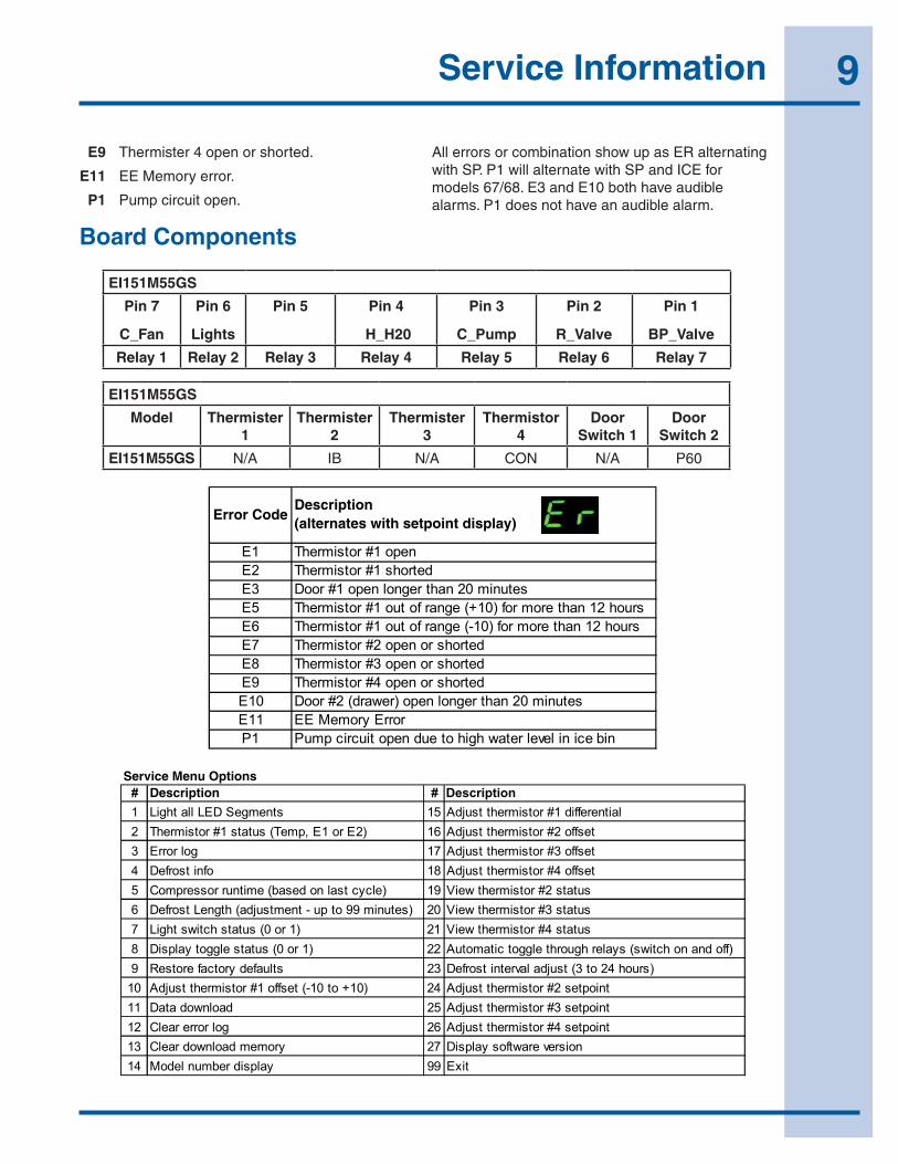
E9 Thermister4openorshorted.
E11 EEMemoryerror.
P1 Pumpcircuitopen.
AllerrorsorcombinationshowupasERalternatingwithSP.P1willalternatewithSPandICEformodels67/68.E3andE10bothhaveaudiblealarms.P1doesnothaveanaudiblealarm.
EI151M55GS
Pin 7
C_Fan
Pin 6
Lights
Pin 5 Pin 4
H_H20
Pin 3
C_Pump
Pin 2
R_Valve
Pin 1
BP_Valve
Relay 1 Relay 2 Relay 3 Relay 4 Relay 5 Relay 6 Relay 7
EI151M55GS
Model Thermister 1
Thermister 2
Thermister 3
Thermistor 4
Door Switch 1
Door Switch 2
EI151M55GS N/A IB N/A CON N/A P60
24
Quick Reference Card
1. Plug in unit.2. The display may show a SP or --, either is OK.3. Install a jumper on J3.4. Hold down warmer, colder,and light button until display shows model numberand main board beeps.5. Use warmer/colder to select new model number.
6. Press and release light key.7. Wait for display to stop flashing.8. Remove jumper from board.9. Unplug unit and wait 5 seconds.10. Plug unit back in.
* Note: Models 2275DWRWS cannot be programmed on thesame board as the other models.
Échelon Model Selection:TRAHC ECNEREFER YALER
Model Part Number
PIN 7C_FAN
PIN 6 LIGHTS PIN 5 PIN 4
H_H2OPIN 3
C_PUMPPIN 2
R_VALVEPIN 1
BP_VALVE
Relay 1 Relay 2 Relay 3 Relay 4 Relay 5 Relay 6 Relay 7
thgiL57/16R5712 Compressor/Fan
thgiL37/17R5112 Compressor/Fan
thgiL47/27CW5112 Compressor/Fan
1 thgiL07
64/78
RRWD5712 Compressor/Fan Pan Heat Mull Heat
CO2175F Cond FanE FAN Light Compressor Hot Gas
Valve DRAIN HEAT IM 1 IM 2
2175RF 65/79 Cond FanE FAN Light Compressor Hot Gas
Valve DRAIN HEAT
CO2175DWR 66/80 Cond FanE FAN Light Compressor Hot Gas
Valve MULL HEAT IM 1 IM 2
CLR2160 67/81 Cond Fan CompressorHot Gas
Valve/ Water Valve
Circulation Pump
CLRCO2175 68/82 Cond Fan Light CompressorHot Gas
Valve/Water Valve
Circulation Pump Ref Valve Ref Bypass
Valve
Compressor/FanthgiL77136VEB5712
2275DWRWS 85186 Cond Fan Bottom Light Compressor Top Light Bottom Valve Top Valve
61-2175R 120V62-2175WC 120V63-2175BEV 120V64-CO2175F 120V65-2175RF 120V66-CO2175DWR 120V67-CLR2160 120V68-CLRCO2175 120V70-2175DWR 120V71-2115R 120V72-2115WC 120V73-2115R 220V
74-2115WC 220V75-2175R 220V76-2175WC 220V77-2175BEV 220V78-CO2175 220V79-2175RF 220V80-CO2175DWR 220V81-CLR2160 220V82-CLRCO2175 220V85-2275DWRWS 120V*86-2275DWRWS 220V*
E1 Thermistor #1 openE2 Thermistor #1 shortedE3 Door #1 open longer than 20 minutesE5 Thermistor #1 out of range (+10) for more than 12 hoursE6 Thermistor #1 out of range (-10) for more than 12 hoursE7 Thermistor #2 open or shortedE8 Thermistor #3 open or shortedE9 Thermistor #4 open or shortedE10 Door #2 (drawer) open longer than 20 minutesE11 EE Memory ErrorP1 Pump circuit open due to high water level in ice bin
## Description
laitnereffid 1# rotsimreht tsujdA51stnemgeS DEL lla thgiL12 Thermistor #1 status (Temp, E1 or E2) 16 Adjust thermistor #2 offset
tesffo 3# rotsimreht tsujdA71gol rorrE3tesffo 4# rotsimreht tsujdA81ofni tsorfeD4
5 Compressor runtime (based on last cycle) 19 View thermistor #2 status6 Defrost Length (adjustment - up to 99 minutes) 20 View thermistor #3 status7 Light switch status (0 or 1) 21 View thermistor #4 status8 Display toggle status (0 or 1) 22 Automatic toggle through relays (switch on and off)
)sruoh 42 ot 3( tsujda lavretni tsorfeD32stluafed yrotcaf erotseR910 Adjust thermistor #1 offset (-10 to +10) 24 Adjust thermistor #2 setpoint
tnioptes 3# rotsimreht tsujdA52daolnwod ataD11tnioptes 4# rotsimreht tsujdA62gol rorre raelC21
noisrev erawtfos yalpsiD72yromem daolnwod raelC31tixE99yalpsid rebmun ledoM41
Board Components
10 Service Information
25
Échelon Electronic Control Quick Guidestne
mmo
Cyalpsi
DhcuoT
hcuoTksaT
sdnoceS 01 dlo
Hff
O/nO
1or
or
2To
ggle
Lig
hts
Touc
h on
ce to
get
into
set
mod
e, th
en to
uch
to a
djus
t.Fl
ashi
ngro
rot-p
oint
eS tsujd
A3
sdnoceS 5 dlo
H)1T( erutarep
meT lautcA
weiV
4W
C w
ill s
crol
l top
/mid
dle/
botto
m te
mpe
ratu
res.
4-2 srotsimrehT llorc
Ssdnoce
S 5 dloH
)4T-2T( erutarepmeT lautc
A wei
V5
dloH
C - F elggoT6
dloH
edoM
moorwoh
S elggoT7
dloH
edoM ecivre
S8
Use
up
or d
own
arro
ws
to s
crol
l. M
ust s
crol
l up
to 9
9 an
d to
uch
LIG
HT
to e
xit.
dloH
elggoT yalpsiD
9D
ispl
ay c
ontro
l LE
Ds
whi
le d
oor i
s cl
osed
(gla
ss d
oor
mod
els
only
)
No
disp
lay
in b
lack
out m
ode
sdnoceS 01 dlo
Hedo
M tuokcalB
01
dloH
elcyC nael
C11
dloH
edoM ff
O rekamecI
21
dloH
tsevraH decroF
41A
udib
le a
lert
whe
n en
terin
g th
is m
ode
dloH
tsorfeD rotaregirfe
R decroF51
Aud
ible
ale
rt w
hen
ente
ring
this
mod
e
dloH
tnemtsujd
A ssenkcihT ecI61
Use
WA
RM
ER
/CO
LDE
R to
scr
oll.
dloH
dloH
)edoM eciff
O( nwodtuh
S yraropmeT
71Ic
emak
er w
ill a
utom
atic
ally
turn
bac
k on
in th
ree
hour
s.
sutatS yale
R81
Rel
ay N
umbe
r with
1 o
r 0 to
indi
cate
on
or o
ff. R
elay
3
is o
ff in
this
exa
mpl
e.
dloH
)repmuj hti
w( rebmu
N ledoM egnah
C91
CLR
CO
2175
di s
play
ed in
this
exa
mpl
e
2275
DW
RW
S M
odel
s fo
r Tem
pera
ture
Set
tings
and
to V
iew
Tem
pera
ture
stnem
moC
yalpsiD
hcuoThcuoT
ksaT
Hol
d 5
Sec
onds
Ligh
ts (T
op a
nd B
otto
m D
raw
er)
1 2A
djus
t Set
-poi
nt (T
op D
raw
er)
Togg
les
light
from
alw
ays
on (o
ff af
ter 4
hou
rs) a
nd o
n w
ith d
raw
er o
pen.
Afte
r 10
seco
nds
of in
activ
ity, s
et-p
oint
will
be s
tore
d.
Each
dis
play
will
indi
cate
tem
pera
ture
of a
djac
ent d
raw
er.
Touc
h on
ce to
get
into
set
mod
e, th
en to
uch
to a
djus
t. Af
ter s
ettin
g to
pte
mpe
ratu
re, t
ouch
LIG
HT
to e
nter
mod
e to
set
bot
tom
tem
pera
ture
.
Flas
hing
3A
djus
t Set
-poi
nt (B
otto
m D
raw
er)
4V
iew
Act
ual T
empe
ratu
re (T
1-T2
)
Flas
hing
Flas
hing
Flas
hing
or
orth
en(b
otto
m b
ar o
n F
flash
ing)
Flas
hing
Electronic Control Quick Guide

11Service Information
Keypad Options
WARNINGElectrocution can cause death or serious injury. Burns from hot or cold surfaces can cause serious injuty. Take precautions when servicing this unit. • Disconnectthepowersource.
• Donotstandinstandingwaterwhenworkingaroundelectricalappliances.
• Makesurethesurfacesyoutoucharenothotorcold.
• Donottouchabarecircuitboardunlessyouarewearingananti-staticwriststrapthatisgroundedtoanelectricalgroundorgroundedwaterpipe.
• Handlecircuitboardscarefullyandavoidtouchingcomponents.
When touching key combinations in which you hold one key and press another key three times, it is important to carefullt follow this procedure:
1. Holdthedesiredkeyensuringthelightabovethekeyislit.
2. Presstheotherkeythreetimes,ensuringitlightsupeachtime.
3. Releasetheheldkeyonlyafterreleasingthepressedkeyforthethirdtime.
Except as noted, these functions are available on all models.
ON/OFFTheON/OFFmodeallowstheunittobeturnedonandoffviathekeypad.Todothis,holdthekeyforapproximately10secondsuntilthe“F”beginstoflash.Releasethekeyandtheunitwillswitchmodes.
Thismodedoesnotdisconnectpowerfromthecircuitboardsiitisstill“LIVE”.
Viewing Actual TemperatureInviewingtemperatureinthesemodesanyoffsetsaretakenintoaccount.Thismeansthatifyouplaceathermistorinaknowntemperature,icewaterforexample,itmaynotread32°Fthatyouwouldassume.Ifthecontroloffsetwaspresetat-3°Fwhileyouplacedthethermistorinanicebath,theactualthermistorreadingwhebviewing
actualtemperaturewouldread35°F.Intheunitthiswouldcausethecabinettopushitself3°cooler.tovirepurethermistorreadingsyoumustgointotheServiceMenuandchoosethecorrectoption.
Toviewthethermistortemperature,holdtheWARMERkeyforapproximatelyfivesecondsuntilthe“F”flashes.Releaseandthedisplaywillshowthecorrectedrefrigeratortemperature.ForWineCoolermodels,thedisplaywillcyclethroughallthreezones.Thesetemperaturesareapproximateandcalibratedforacabinetinnormalambienttemperatureswithsomeproductload.Checkingacompletelyunloadedcabinetmayresultinothertemperatures.
Changing from Fahrenheit to CelsiusTochangethedisplayedtemperaturefrom°Fto°C,holdtheLIGHTkeyandpressCOLDERthreetimes.Thiswillchangeallvaluesto°C.Whenthekeycombinationisacceptedthecontrolwillchangevalues.
Showroom ModeThismodeisdesignedtoshowunitsinadisplayenvironment.Wheninthismodetheonlyfunctionswillbethecontrolsandcabinetlights.Thecompressor,fans,etc.willnotoperate.Toenterthismode,holdtheCOLDERkeyandpresstheLIGHTbuttonthreetimes.Whenentered,thedegreesymbolwillbetoflash.Whenthedegreesymbolisflashingtheunitwillallowtheuseofthecontrolfordemonstrations.Afternottouchingtheunitforoneminutethedisplaywillbeginto“snake”around.Thisismeanttoalertyoutheunitisinshowroommode.Theunitcanbeleftinthismodeindefinitely.Ifyouagainwanttodemothecontrol,touchanykeyandthedegreesymbolwillbegintoflash.To exit this mode: thismodeneedstobeexitedbythesamekeycombinationasusedtoenterthemode.
Service ModeThismodehas16differentoptionsavailableforservicediagnostics.ToenterthemodeholdtheWARMERkeyandpresstheLIGHTbuttonthreetimes.Thedisplaywillshow“0’.WheninthismodetheWARMERandCOLDERkeyswillactasupanddownarrowstoselectthedesiredoption.TheLIGHTkeyistheENTERkeyandwillenterafunction.ToexittheServiceMode,scrolltooption99andpresstheLIGHTkey.Afterfiveminutesofnottouchinganykeysthemodewillalsoexitautomatically.
12 Service Information
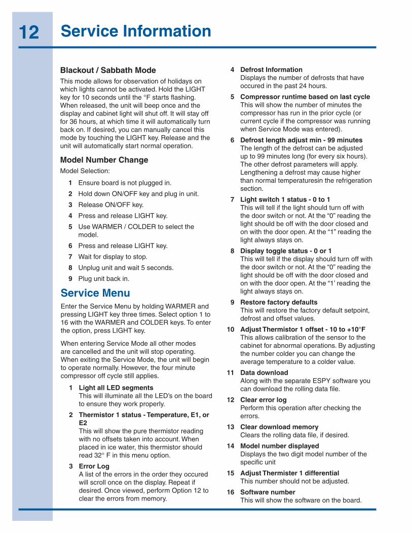
Blackout / Sabbath ModeThismodeallowsforobservationofholidaysonwhichlightscannotbeactivated.HoldtheLIGHTkeyfor10secondsuntilthe°Fstartsflashing.Whenreleased,theunitwillbeeponceandthedisplayandcabinetlightwillshutoff.Itwillstayofffor36hours,atwhichtimeitwillautomaticallyturnbackon.Ifdesired,youcanmanuallycancelthismodebytouchingtheLIGHTkey.Releaseandtheunitwillautomaticallystartnormaloperation.
Model Number ChangeModelSelection:
1 Ensureboardisnotpluggedin.
2 HolddownON/OFFkeyandpluginunit.
3 ReleaseON/OFFkey.
4 PressandreleaseLIGHTkey.
5 UseWARMER/COLDERtoselectthemodel.
6 PressandreleaseLIGHTkey.
7 Waitfordisplaytostop.
8 Unplugunitandwait5seconds.
9 Plugunitbackin.
Service MenuEntertheServiceMenubyholdingWARMERandpressingLIGHTkeythreetimes.Selectoption1to16withtheWARMERandCOLDERkeys.Toentertheoption,pressLIGHTkey.
WhenenteringServiceModeallothermodesarecancelledandtheunitwillstopoperating.WhenexitingtheServiceMode,theunitwillbegintooperatenormally.However,thefourminutecompressoroffcyclestillapplies.
1 Light all LED segments ThiswillilluminatealltheLED’sontheboardtoensuretheyworkproperly.
2 Thermistor 1 status - Temperature, E1, or E2 Thiswillshowthepurethermistorreadingwithnooffsetstakenintoaccount.Whenplacedinicewater,thisthermistorshouldread32°Finthismenuoption.
3 Error Log Alistoftheerrorsintheordertheyoccuredwillscrollonceonthedisplay.Repeatifdesired.Onceviewed,performOption12tocleartheerrorsfrommemory.
4 Defrost Information Displaysthenumberofdefroststhathaveoccuredinthepast24hours.
5 Compressor runtime based on last cycle Thiswillshowthenumberofminutesthecompressorhasruninthepriorcycle(orcurrentcycleifthecompressorwasrunningwhenServiceModewasentered).
6 Defrost length adjust min - 99 minutes Thelengthofthedefrostcanbeadjustedupto99minuteslong(foreverysixhours).Theotherdefrostparameterswillapply.Lengtheningadefrostmaycausehigherthannormaltemperaturesintherefrigerationsection.
7 Light switch 1 status - 0 to 1 Thiswilltellifthelightshouldturnoffwiththedoorswitchornot.Atthe“0”readingthelightshouldbeoffwiththedoorclosedandonwiththedooropen.Atthe“1”readingthelightalwaysstayson.
8 Display toggle status - 0 or 1 Thiswilltellifthedisplayshouldturnoffwiththedoorswitchornot.Atthe“0”readingthelightshouldbeoffwiththedoorclosedandonwiththedooropen.Atthe“1’readingthelightalwaysstayson.
9 Restore factory defaults Thiswillrestorethefactorydefaultsetpoint,defrostandoffsetvalues.
10 Adjust Thermistor 1 offset - 10 to +10°F Thisallowscalibrationofthesensortothecabinetforabnormaloperations.Byadjustingthenumbercolderyoucanchangetheaveragetemperaturetoacoldervalue.
11 Data download AlongwiththeseparateESPYsoftwareyoucandownloadtherollingdatafile.
12 Clear error log Performthisoperationaftercheckingtheerrors.
13 Clear download memory Clearstherollingdatafile,ifdesired.
14 Model number displayed Displaysthetwodigitmodelnumberofthespecificunit
15 Adjust Thermister 1 differential Thisnumbershouldnotbeadjusted.
16 Software number Thiswillshowthesoftwareontheboard.
13Service Information
Error Codes E1 Thermostor1isopen.
E2 Thermistor1isshorted.
E3 Maindoororbottomdrawerisopenlongerthan20minutes.
E4 Compressorhas100%runtimebetweentwodefrostcycles.
E5 Thermister1outofrange+10°Fformorethan12hours.
E6 Thermister1outofrange-10°Fformorethan12hours.
All errors show up on display alternating between SP and ER#.
Electronic Control Quick Guide
28
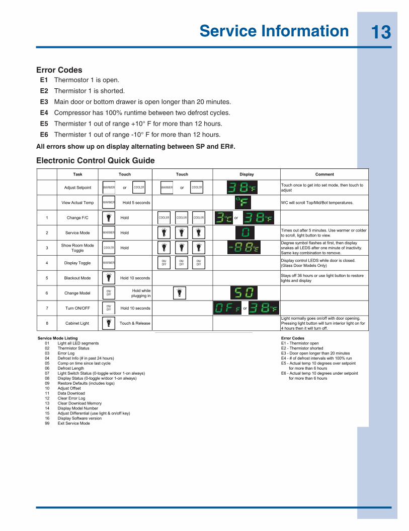
Error CodesE1 Thermistor 1 is open.
E2 Thermistor 1 is shorted.
E3 Main door or bottom drawer is open longer than 20 minutes.
E4 Compressor had 100% runtime between two defrost cycles.
E5 Thermistor 1 out of range + 10°F for more than 12 hours.
E6 Thermistor 1 out of range -10°F for more than 12 hours.
All errors show up on display alternating between SP and ER#.
Origins Electronic Control Quick Guide
ksaT hcuoT hcuoT yalpsiD tnemmoC
tniopteS tsujdA ro ro ot hcuot neht ,edom tes otni teg ot ecno hcuoTtsujda
pmeT lautcA weiV sdnoces 5 dloH .serutarepmet toB/diM/poT llorcs lliw CW
C/F egnahC1 dloH ro
edoM ecivreS2 dloH redloc ro remraw esU .setunim 5 retfa tuo semiT.weiv ot nottub thgil ,llorcs ot
3 edoM mooR wohSelggoT dloH
yalpsid neht ,tsrif ta sehsalf lobmys eergeD .ytivitcani fo etunim eno retfa SDEL lla sekans
.evomer ot noitanibmoc yek emaS
elggoT yalpsiD4 .desolc si rood elihw SDEL lortnoc yalpsiD)ylnO sledoM rooD ssalG(
edoM tuokcalB5 sdnoces 01 dloH erotser ot nottub thgil esu ro sruoh 63 ffo syatSyalpsid dna sthgil
ledoM egnahC6 elihw dloH ni gniggulp
FFO/NO nruT7 sdnoces 01 dloH oro
thgiL tenibaC8 esaeleR & hcuoT .gninepo rood htiw ffo/no seog yllamron thgiL
rof no thgil roiretni nrut lliw nottub thgil gnisserP.ffo nrut lliw ti neht sruoh 4
gnitsiL edoM ecivreS sedoC rorrEstnemges DEL lla thgiL10 nepo rotsimrehT - 1E
sutatS rotsimrehT20 detrohs rotsimrehT - 2EgoL rorrE30 setunim 02 naht regnol nepo rooD - 3E
)sruoh 42 tsap ni #( ofnI tsorfeD40 nur %001 htiw slavretni tsorfed fo # - 4Eelcyc tsal ecnis emit no pmoC50 tnioptes revo seerged 01 pmet lautcA - 5E
htgneL tsorfeD60 sruoh 6 naht erom rof no-1 rood/w elggot-0( sutatS hctiwS thgiL70 )syawla tnioptes rednu seerged 01 pmet lautcA - 6E
wla no-1 rood/w elggot-0( sutatS yalpsiD80 )sya sruoh 6 naht erom rof )sgol sedulcni( stluafeD erotseR90
tesffO tsujdA01daolnwoD ataD11goL rorrE raelC21
yromeM daolnwoD raelC31rebmuN ledoM yalpsiD41
)yek ffo/no & thgil esu( laitnereffiD tsujdA51noisrev erawtfoS yalpsiD61
edoM ecivreS tixE99
:noitceleS ledoM snigirO
e unit is not plugged in.rus ekaM .1 .tinu ni gulp dna yek ffo/no nwod dloH .2
.yek ffo/no esaeleR .3 .yek thgil esaeler dna sserP .4
edom eht tceles ot redloc/remraw esU .5 rebmun l .derised
V021 R5711-94 .a V021 CW5711-05 .b V021 VEB5711-15 .c
V022 R5711-25 .d V022 CW5711-35 .e V022 VEB5711-45 .f
V021 R5111-65 .g V022 R5111-75 .h
V021 CW5111-77 .i V022 CW5111-87 .j .yek thgil esaeler dna sserP .6
.pots ot gnihsalf rof tiaW .7 .sdnoces 5 tiaw-tinu gulpnU .8
.9 .ni kcab tinu gulP
REMRAW RELOOC
REMRAW
REMRAW
REMRAW
REMRAW
RELOOC
RELOOC RELOOC RELOOC
RELOOC
/NOFFO
/NOFFO
/NOFFO
/NOFFO
/NOFFO
14 Service Information
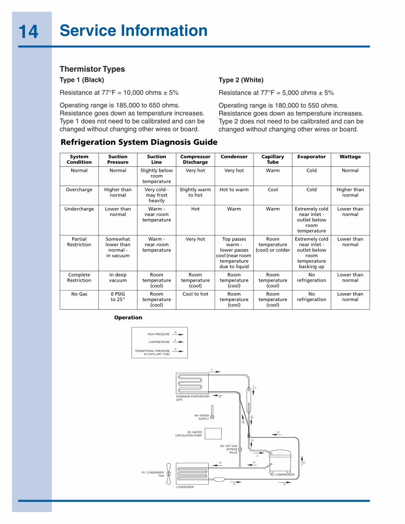
Thermistor TypesType 1 (Black)
Resistanceat77°F=10,000ohms±5%
Operatingrangeis185,000to650ohms.Resistancegoesdownastemperatureincreases.Type1doesnotneedtobecalibratedandcanbechangedwithoutchangingotherwiresorboard.
Type 2 (White)
Resistanceat77°F=5,000ohms±5%
Operatingrangeis180,000to550ohms.Resistancegoesdownastemperatureincreases.Type2doesnotneedtobecalibratedandcanbechangedwithoutchangingotherwiresorboard.
36
Model CLR2160
Operation
Figure 1
HIGH PRESSURE
LOWPRESSURE
TRANSITIONAL PRESSUREIN CAPILLARY TUBE
H
L
C
L
L
C
C
C
C
C
L
L
HH
C
L
ICEMAKER EVAPORATOR2276
R4: WATERSUPPLY
R5: WATERCIRCULATION PUMP
R4: HOT GASBYPASS
VALVE
R1: CONDENSERFAN
CONDENSER
R3: COMPRESSOR
RELAY R1 R3 R4 R5
FUNCTION FAN
ON
ON
OFF
OFF
OFF
ON
ON
OFF
OFF
OFF
OFF
ON
OFF
ON/OFF
ON*
ON
OFF
OFF
ON/OFF
OFF
COMP CIRC PUMPHOT GAS /WATER IN
Mode 1:Ice MakingMode 2:Ice HarvestMode 3:OffMode 4:CleaningMode 5:Water Fill &Initial Start-Up* Normal Start-Up lasts 3 minutesNote: R2, R6 and R7 not used
29
Thermistor Types
Type 1 (Black)
Resistance at 77°F = 10,000 Ohms ± 5%
Operating range is 185,000 to 650 Ohms. Resistance goes down as temperature increases. Type 1 does not need to be calibrated and can be changed without changing other wires or board.
Type 2 (White)
Resistance at 77°F = 5,000 Ohms ± 5%
Operating range is 180,000 to 550 Ohms. Resistance goes down as temperature increases. Type 2 does not need to be calibrated and can be changed without changing other wires or board.
Refrigeration System Diagnosis Guide
System Condition
Suction Pressure
Suction Line
Compressor Discharge
Condenser Capillary Tube
Evaporator Wattage
Normal Normal Slightly below room
temperature
Very hot Very hot Warm Cold Normal
Overcharge Higher than normal
Very cold -may frost
heavily
Slightly warm to hot
Hot to warm Cool Cold Higher than normal
Undercharge Lower than normal
Warm -near room
temperature
Hot Warm Warm Extremely cold near inlet -
outlet below room
temperature
Lower than normal
Partial Restriction
Somewhat lower than
normal -in vacuum
Warm - near room
temperature
Very hot Top passes warm -
lower passes cool (near room
temperature due to liquid
Room temperature
(cool) or colder
Extremely cold near inlet -
outlet below room
temperature backing up
Lower than normal
Complete Restriction
In deep vacuum
Room temperature
(cool)
Room temperature
(cool)
Room temperature
(cool)
Room temperature
(cool)
No refrigeration
Lower than normal
No Gas 0 PSIG to 25"
Room temperature
(cool)
Cool to hot Room temperature
(cool)
Room temperature
(cool)
No refrigeration
Lower than normal
15Service Information
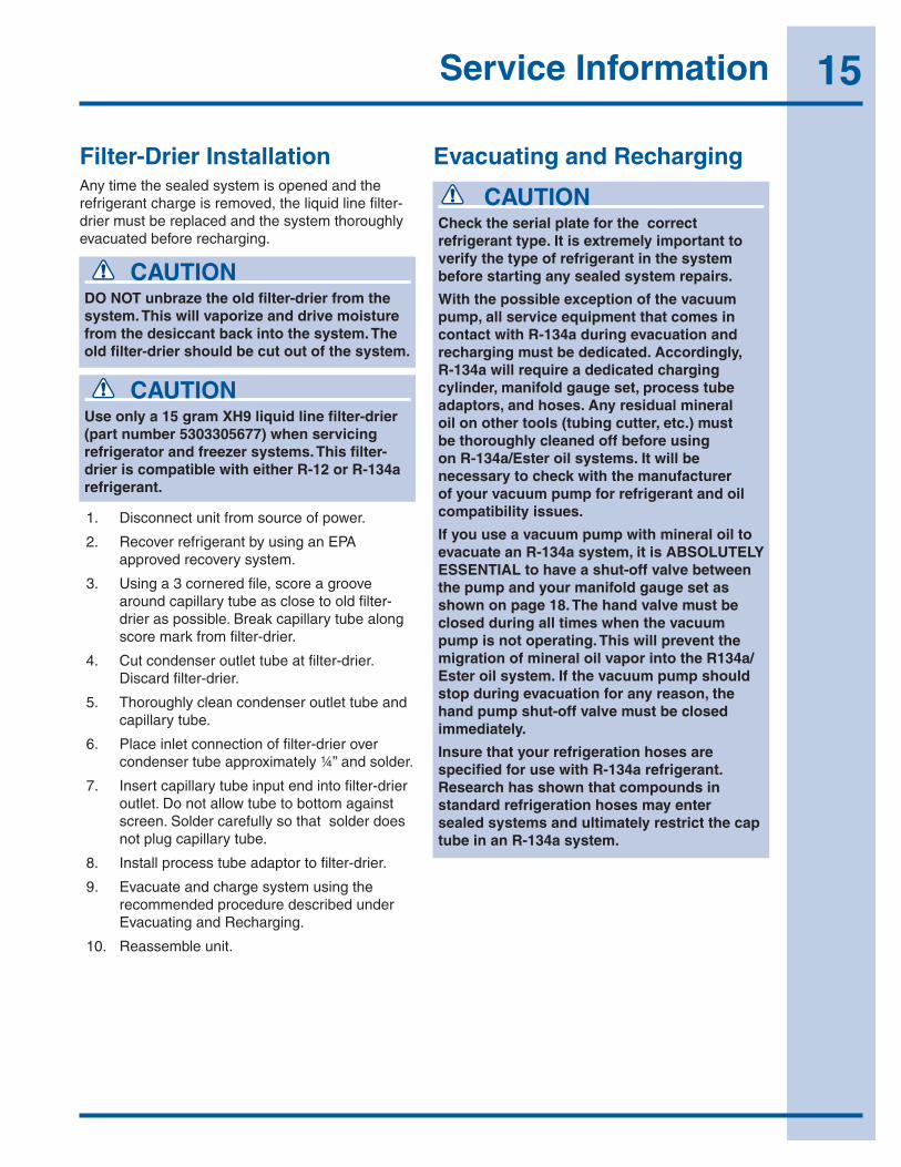
Filter-Drier InstallationAnytimethesealedsystemisopenedandtherefrigerantchargeisremoved,theliquidlinefilter-driermustbereplacedandthesystemthoroughlyevacuatedbeforerecharging.
CAUTIONDO NOT unbraze the old filter-drier from the system. This will vaporize and drive moisture from the desiccant back into the system. The old filter-drier should be cut out of the system.
CAUTIONUse only a 15 gram XH9 liquid line filter-drier (part number 5303305677) when servicing refrigerator and freezer systems. This filter-drier is compatible with either R-12 or R-134a refrigerant.
1. Disconnectunitfromsourceofpower.
2. RecoverrefrigerantbyusinganEPAapprovedrecoverysystem.
3. Usinga3corneredfile,scoreagroovearoundcapillarytubeasclosetooldfilter-drieraspossible.Breakcapillarytubealongscoremarkfromfilter-drier.
4. Cutcondenseroutlettubeatfilter-drier.Discardfilter-drier.
5. Thoroughlycleancondenseroutlettubeandcapillarytube.
6. Placeinletconnectionoffilter-drierovercondensertubeapproximately¼”andsolder.
7. Insertcapillarytubeinputendintofilter-drieroutlet.Donotallowtubetobottomagainstscreen.Soldercarefullysothatsolderdoesnotplugcapillarytube.
8. Installprocesstubeadaptortofilter-drier.
9. EvacuateandchargesystemusingtherecommendedproceduredescribedunderEvacuatingandRecharging.
10. Reassembleunit.
Evacuating and Recharging
CAUTIONCheck the serial plate for the correct refrigerant type. It is extremely important to verify the type of refrigerant in the system before starting any sealed system repairs.
With the possible exception of the vacuum pump, all service equipment that comes in contact with R-134a during evacuation and recharging must be dedicated. Accordingly, R-134a will require a dedicated charging cylinder, manifold gauge set, process tube adaptors, and hoses. Any residual mineral oil on other tools (tubing cutter, etc.) must be thoroughly cleaned off before using on R-134a/Ester oil systems. It will be necessary to check with the manufacturer of your vacuum pump for refrigerant and oil compatibility issues.
If you use a vacuum pump with mineral oil to evacuate an R-134a system, it is ABSOLUTELY ESSENTIAL to have a shut-off valve between the pump and your manifold gauge set as shown on page 18. The hand valve must be closed during all times when the vacuum pump is not operating. This will prevent the migration of mineral oil vapor into the R134a/Ester oil system. If the vacuum pump should stop during evacuation for any reason, the hand pump shut-off valve must be closed immediately.
Insure that your refrigeration hoses are specified for use with R-134a refrigerant. Research has shown that compounds in standard refrigeration hoses may enter sealed systems and ultimately restrict the cap tube in an R-134a system.
16 Service Information
Toachievetherequiredlevelsofevacuation,aproperlymaintainedtwostagevacuumpumpingoodconditionisrequired.Itisabsolutelyessentialtomaintainyourvacuumpumpaccordingtothemanufacturer’sinstructionsincludingrequiredoilchangesattherecommendedintervals.Vacuumpumpoilshouldalwaysbechangedafterevacuatingacontaminatedsystem.
Vacuumpumpperformanceshouldbecheckedperiodicallywithamicrongauge.
1. Makecertainthatchargingcylindervalve,handshut-offvalve,andmanifoldgaugevalvesareclosed.
2. Startvacuumpump.
3. Openhandshut-offvalveandslowlyopenbothmanifoldvalves,turningcounterclockwise,fortwofullrotations.
WARNINGR-134a systems are particularly susceptible to moisture contamination which can only be prevented by evacuating the system for a minimum of 30 minutes to attain a minimum 29.9 inch (500 micron or lower) vacuum.
4. Operatethevacuumpumpforaminimumof30minutestoaminimumof29.9”(500micron)vacuum.
NOTEOnproductswithLowsideleaksyoumustheatthecrankcaseareaofthecompressorthoughoutthe30minutesyouarerunningyourvacuumpumptopullavacuumonthesystem.Every4to5minuteswhileyouarerunningyourvacuumpumpandheatingthecrankcaseareashakethecompressor.Byheatingthecrank-caseyouareheatingtheoilinthecompressor.Thiswilldrivethemoistureoutoftheoil.Byshakingthecompressorthiswillallowthemoisturetocometothetopoftheoilfastersothevacuumpumpcanremovethemoisturefromthesystem.
CAUTIONIf high vacuum equipment is used, just crack both manifold valves for a few minutes and then open slowly for the two full turns counterclockwise. This will prevent the compressor oil from foaming and being drawn into the vacuum pump.
Evacuating SystemEquipment Needed for Evacuation & Recharging:• Heatedchargingcylinder
• Standard3-portmanifoldgaugeset:
-4charginghoses
-Teefittingwithvalvecorestemremoved(RobinairNo.40396)
-Handshut-offvalve(RobinairNo.40380)
• Twostagevacuumpump
• Processtubeadapterkit(RobinairNo.12458)
• Tubingcutter
• Pinch-offtoolcapableofmakingleakproofseal
• Completebrazingtorchset
• Small3-cornerfile
• GritclothorScotch-Brite
• 45%silversolderandflux
• HeatGun
Installing Evacuation and Recharging Equipment1. Disconnectrefrigeratorfromelectricalsupply.
2. Ifcompressorwasreplaced,installcorrectsizedprocesstubeadaptoronprocesstube.Ifcompressorwasnotreplaced,cutprocesstubewithtubingcutterleavingasmuchtubeaspossibleandinstallcorrectsizeprocesstubeadaptor.
3. Installcorrectsizedprocesstubeadaptoronhigh-sideprocesstube.
4. Attachrefrigerationservicegaugemanifoldtosysteminfollowingorder:
• Low-side(compoundgauge)hosetosuctionsideprocesstubeadaptor.
• High-side(pressuregauge)hosetohigh-sideprocesstubeadaptor.
• Centerportmanifoldhosebeforehandshut-offvalvetochargingcylinder.
• Centerportmanifoldhoseafterhandshut-offvalvetovacuumpump.
17Service Information
NOTEProcessvalvesarenottobeleftonthetubinginanyapplication,exceptthevalveonEMAServicedrierpart#5303918288.
5. Closehandshut-offvalvetovacuumpump.Watchcompoundgaugeforseveralminutes.Ifreadingrises,thereisaleakinthesystem,gotostep6.Ifnoleakisindicated,stopvacuumpump.Systemisnowreadyforcharging.
6. Ifaleakisindicated,stopvacuumpumpandintroduceasmallchargeofrefrigerantintosystembycrackingvalveonbottomofchargingcylinderuntilsystemispressurizedto40or50lbspsig.
7. Leaktestlow-side.Closecompoundgauge.Runcompressorforafewminutesandleaktesthigh-side.Whenleakisfound,recapturerefrigerantusingEPAapprovedrecoverysystemRepairandgobacktostep1.
CAUTIONCheck the serial plate for the correct refrigerant type. It is extremely important to verify the type of refrigerant in the system before starting any sealed system repairs.
After charging the system with liquid be certain to wait at least 5 minutes before starting the compressor to give the refrigerant a chance to disperse throughout the system. Otherwise the compressor could be damaged by attempting to pump excessive quantities of liquid.
Preparing The Charging Cylinder:
1. Makecertainthathandshut-offvalvetovacuumpumpisclosed.
2. Closehigh-sidemanifoldgaugevalve.
3. Setchargingcylinderscaletopressureindicatedoncylinderpressuregauge.
4. Observerefrigerantlevelinsightglass.Subtractamounttobechargedintosystemandnoteshutoffpoint.
5. Openchargingcylindervalveslowlyandallowproperchargetoentersystem.
6. Assoonasrefrigerantinsightglasshasgonedowntopredeterminedlevel,closechargingcylindervalve.
7. Allowsystemtositforfiveminutes.
8. Turnonrefrigeratorcompressor.Runcompressorforafewminutesandmonitorsystempressures.
9. Whensatisfiedthattheunitisoperatingcorrectly,clampthehigh-sideprocesstubewiththepinch-offtoolwhiletheunitisstillrunning.
10. Slowlyopenthehigh-sidemanifoldgaugevalvetoallowthecompressortoremoveanyrefrigeranttrappedinthehigh-sidehoseandtheprocessfitting.
11. Closebothofthemanifoldgaugevalves.Ifthehigh-sidegaugereadingrises,thepinch-offmustbecorrectedbeforeproceeding.
12. Removethehigh-sideprocesstubeadaptorandsoldertheprocesstubeclosed.
13. Clampthelow-sideprocesstubewiththepinch-offtoolwhiletheunitisrunning.Removethelow-sideprocesstubeadaptorandsoldertheprocesstubeclosed.
14. Checktheprocesstubesforrefrigerantleaks.
WARNINGDisconnect the charging cylinder heater at this time to prevent the cylinder pressure from exceeding its maximum limits.
Final Leak Test
1. WiththerefrigeratorturnedOFFleaktestalllow-sidesystemcomponents.
2. TurntheunitONandrununtilthecondenseriswarm.Leaktestthehigh-sidesystemcomponents.
Charging The System
18 Service Information
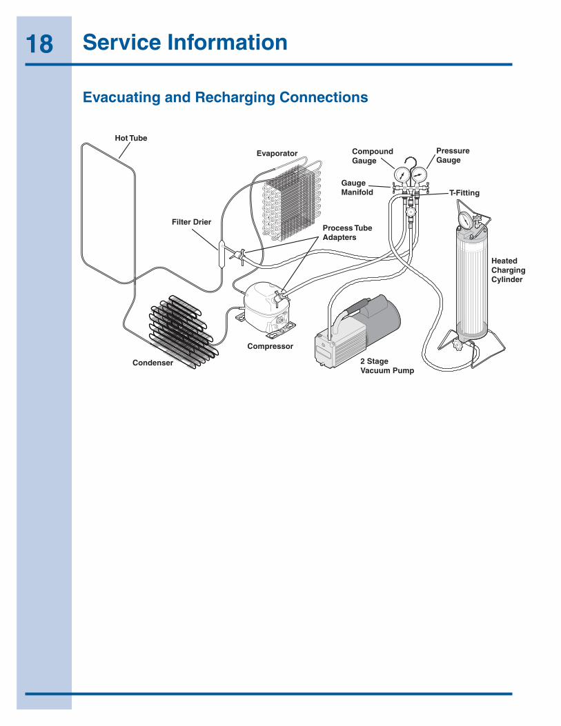
Hot Tube
Evaporator
Condenser
Compressor
2 StageVacuum Pump
HeatedChargingCylinder
Process TubeAdapters
Filter Drier
PressureGauge
CompoundGauge
GaugeManifold T-Fitting
Evacuating and Recharging Connections

19Service Information
Verify Refrigerant Type In The System
Forexample,hosesthatwereusedforarefrigerationsystemoperatingonR-12maycontainsmallquantitiesofmineraloilwhichcanblockthecapillarytubeinasystemoperatingonR-134a.Aslittleasonemilligrammaybesufficienttocauseablockage.Inaddition,sealedsystemcomponentsthathavebeenusedwithCFCsystemsmustnotbeusedwithR-134asystems.ThesecomponentsmaycontainresidualamountsofrefrigerantandoilwhichcoulddamageanR-134asystem.
NOTICEInstructionsgivenherearefurnishedasaguide.Personsattemptingtousetheseinstructionstomakerepairstothesealedrefrigerationsystemshouldhaveaworkingknowledgeofrefrigerationandprevioustrainingonsealedsystemrepair.
CAUTIONR-134a and R-12 are completely incompatible. Before starting any sealed system repair, it is extremely important to check serial plate of product to verify the type of refrigerant in the system.
Dedicated EquipmentR-134amustnotbemixedwithothertypesofrefrigerants.R-134amustberecoveredindedicatedandproperlyidentifiedrecoverybagsandtanks.
ItwillbenecessarytocheckwiththemanufacturerofyourrecoveryequipmenttodetermineR-134acompatibility.Somerecoveryequipmentmanufacturershavechangeoverinstructionsforswitchingbetweenrefrigeranttypes.Protectyourselfandyourequipmentbyfollowingallmanufacturerguidelines.
Also,ensurethatyourrefrigerationhosesarespecifiedforusewithR-134arefrigerant.ResearchhasshownthatcompoundsinstandardrefrigerationhosesmayentersealedsystemsandultimatelyrestrictthecaptubeinanR-134asystem.
R-134a Refrigeration SystemsThesealedrefrigerationsystemwillconsistofthesamebasiccomponentsbeingutilizedintheR-12systems.
Thereisa10%to15%dischargepressureincreaseusingR-134a,witha5%to10%decreaseinsuctionpressurewhencomparedtothesameproductwithanR-12systemoperatingat90°F(32°C)ambienttemperatureconditions.LowersuctionpressuresresultfromthelowerdensityofR-134arefrigerantwhicheffectsrefrigerantflowrate.R-134asystemscommonlyoperateina1”-2”vacuumonthesuctionside.
ProductsusingR-134arefrigerantwillgenerallyhavealongercapillarytubetomaintainasimilarflowrateandsomemodelswillhavealargercondensertoreducethedischargepressuresandlowerstart-upsoundtransmission.
Miscibility of R-134a and Ester OilAspecialsyntheticoilknownasEsteroilisusedasalubricantinrefrigerationsystemsoperatingonR-134a.Esteroilsareproducedfromalcoholsandfattyacidsandareavailableinseveraldifferentvariants.Esteroilshaveapleasantaromareminiscentoffruit.
Esteroilsgenerallyincludevarioustypesofadditivesforimprovingcertainpropertiessuchasviscosity,temperaturesensitivity,etc.Theseadditivesareoftenaggressive,andskincontactwithEsteroilsshouldthereforebeavoided.
Oneofthemostimportantrequirementsmadeonarefrigerantsystemisthattheoilmixwiththerefrigerant.SincemineraloilandordinarysyntheticoilDONOTmixwithR-134a,Esteroilisusedforlubrication.EsteroildissolvesinR-134a.
EsteroilisbrokendownbychlorineandcannotbeusedwithR-12(R-12containschlorine)oranyothercompoundcontainingchlorine.Therefore,R-134arefrigerationsystemshavevirtuallynotoleranceforchlorinemoleculesfromCFCrefrigerants(R-134aisanHFCandcontainsnochlorine).
CAUTIONDuring R-134a service, it is extremely important to avoid using equipment that may contain residual amounts of mineral oil, CFC’s or HCFC’s which could enter and contaminate the sealed system.

20 Service Information
AttheearlieststageofdevelopmentworkonR-134a,testswerecarriedoutonadifferenttypeofsyntheticoilknownasPoly-AlkalineGlycol(PAG).Thisoilisalsousedincertainairconditioningsystemsforcars.PAGandEsteroilDONOTmixwithoneanother.ServiceequipmentusedforR-134a/EsteroilmustnotcomeintocontactwithPAG.
Water In The Refrigeration SystemEveninverysmallquantities,waterinanyrefrigerationsystemcancausethefollowingproblems:
•Iceplugsincapillarytubes.
•Copperplatingincompressor.
•Reactionswithorganicmaterialsinsystems.
•Corrosionofmetals.
R-134aandEsteroilwillaggravatetheproblemofwaterintherefrigerationsystem.Esteroilmayreactwithwatervaporandishydroscopic(itwillabsorbwaterifitcomesincontactwithhumidair).WaterisalsomoresolubleinR-134athanR-12.
Tominimizethewatercontentwheneverserviceworkisperformed,therefrigerationsystemshouldalwaysbethoroughlyevacuatedthroughprocesstubeadaptorsonboththehighandlowsidesofthesystem.Evacuationmustbeforaminimumof30minutestoatleasta29.9inch(500micron)vacuum.
Toachievetherequired29.9inch(500micron)vacuum,aproperlymaintainedtwo-stagevacuumpumpingoodconditionisrequired.Atwostagepumpcanreachadeepervacuumthanasinglestagebecausetheexhaustfromthefirstpumpingstageisdischargedintothesecondpumpingstage.Thismeansthesecondstagebeginspumpingatalowerpressuresoalowerultimatevacuumcanbeachieved(See2-StageVacuumPump,FigureE3).
VACUUM CHART
Vacuum Inches Hg. Microns Boiling Point
of Water °F
28.940 25000 77.9
29.530 10000 52.0
29.832 4600 32.0
29.882 1000 1.0
29.901 500 -11.2
29.915 150 -32.8
29.917 100 -38.2
29.919 50 -49.0
Vacuum Pump MaintenanceItisabsolutelyessentialtomaintainyourvacuumpumpaccordingtothemanufacturer’sinstructionsincludingrequiredoilchangesattherecommendedintervals.Vacuumpumpoilshouldalwaysbechangedafterevacuatingacontaminatedsystem.Vacuumpumpperformanceshouldbecheckedperiodicallywithamicrongauge.
Vacuumpumpsuppliersmayormaynotrecommendchangingthevacuumpumpoiltothesametypethat’sinthesystembeingevacuated.Somemanufacturersmayrecommendavacuumpumpthat’sdedicatedtoR-134asystems.
Robinairhasstatedthattheircurrentanddiscontinuedvacuumpumpmodels,usingmineraloilcurrentlyspecifiedforuseintheirvacuumpumps,canbeusedtoevacuateR-134a/Esteroilsystems.RobinairalsostatesthatitisacceptabletoalternatebetweenevacuatingR-12/mineraloilandR-134a/Esteroilsystemswithoutadverselyeffectingthevacuumpump’sperformance.
Forotherbrandsofvacuumpumps,checkwiththemanufacturerforrestrictionsandguidelineswhenusingwithR-134a.
2-Stage Vacuum Pump
Figure E3
21Service Information
CAUTIONIf you use a vacuum pump with mineral oil to evacuate an R-134a system, it is ABSOLUTELY ESSENTIAL to have a shut-off valve between pump and your manifold gauge set as shown in Figure E2. The hand valve must be closed during all times when vacuum pump is not operating. This will prevent migration of mineral oil vapor into R134a/Ester oil system. If vacuum pump should stop during evacuation for any reason, the hand pump shut-off valve must be closed immediately.
Refrigerant LeaksAsystemwithR-134aandEsteroilwillbecomesaturatedwithmoisturemuchfasterthanasystemwithR-12andmineraloil.Ifyourleakwasinthelowsideoftherefrigerationsystemwhenthecompressorisrunningthepressureinthelowsidewillgointoavacuum.Asadditionalrefrigerantleaksoutthesystemwillgodeeperintoavacuum.Thesystemrunninginthisvacuumwillallowairandmoisturetobepulledintothesealedsystem.ThemoisturepulledincanthenbemixedintotheEsteroilinthecompressor.
Iftheproducthashadalowsideleakyouwillneedtoinstallthetwostageservicedryerfilterpartnumber5303918288.Youmustheatthecrankcaseareaofthecompressorusingaheatgunonthehighheatsettingthoughoutthe30minutesyouarerunningyourvacuumpumptopullavacuumonthesystem.Every4to5minuteswhileyouarerunningyourvacuumpumpandheatingthecrankcaseareashakethecompressor.Byheatingthecrank-caseyouareheatingtheoilinthecompressor.Thiswilldrivethemoistureoutoftheoil.Byshakingthecompressorthiswillallowthemoisturetocometothetopoftheoilfastersothevacuumpumpcanremovethemoisturefromthesystem.
Electrolux Home products does not approve the use of the Sweep Charge for sealed system repair. Thismethodofservicingsealedsystemsweknowisoftenusedtorepairproductsinthefield.TheSweepChargedoesnotadequatelyremovethemoisturefromtheoilinthecompressor. InaR-134asystemyouwillneedtoreplacedthecompressoriftheproducthashadalowsideleakandyouareservicingwiththeSweepChargeprocedure.
R-134arefrigerantmoleculesaresmallerthan
R-12molecules.ThismeansthatR-134awillpassmoreminorleaksandtherateofflowwillbegreaterthanforR-12.Therefore,itisnowmoreimportantthanevertofollowgoodbrazingpractices.Useagoodgradeofsilversolder.45%silversolderisrecommended.
Leak DetectionR-134asystemleakscanbepinpointedbymeansofanelectronicleakdetectororbybubblesolution.
ElectronicleakdetectorsforR-134aservicearecurrentlyavailablefromseveralmanufacturers.Theleastexpensivemodelsarenon-selectivedetectorsthatwilldetectanytypeofemissionorvaporpresent,regardlessofitschemicalcomposition.Somenon-selectivedetectorsdesignedforusewithR-12mayhaveamuchlowersensitivitywhenusedwithR-134a.However,newlydesigneddetectorswithgoodR-134asensitivityarenowavailable.Besuretoconsultwiththemanufacturerbeforeselectingorusinganon-selectivedetectorwithR-134a.
Halogen-specificdetectorsuseaspecializedsensorthatallowsdetectionofcompoundscontainingchlorine,fluorine,bromine,andiodinewithoutbeingactiviatedbyotherspecies.Themajoradvantageofthistypeofdetectorisareductioninthenumberof“nuisancealarms”.Halogen-specificdetectorsaregenerallymoreexpensivethannon-selectivedetectorsbutfeaturehighersensitivity.
22 Service Information
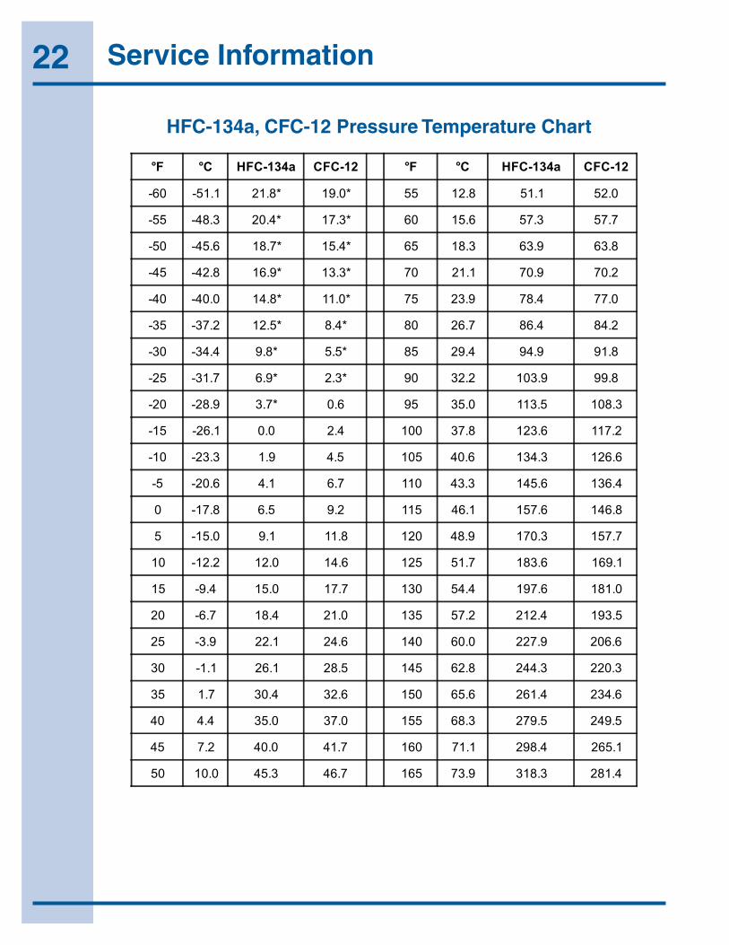
°F °C HFC-134a CFC-12 °F °C HFC-134a CFC-12
-60 -51.1 21.8* 19.0* 55 12.8 51.1 52.0
-55 -48.3 20.4* 17.3* 60 15.6 57.3 57.7
-50 -45.6 18.7* 15.4* 65 18.3 63.9 63.8
-45 -42.8 16.9* 13.3* 70 21.1 70.9 70.2
-40 -40.0 14.8* 11.0* 75 23.9 78.4 77.0
-35 -37.2 12.5* 8.4* 80 26.7 86.4 84.2
-30 -34.4 9.8* 5.5* 85 29.4 94.9 91.8
-25 -31.7 6.9* 2.3* 90 32.2 103.9 99.8
-20 -28.9 3.7* 0.6 95 35.0 113.5 108.3
-15 -26.1 0.0 2.4 100 37.8 123.6 117.2
-10 -23.3 1.9 4.5 105 40.6 134.3 126.6
-5 -20.6 4.1 6.7 110 43.3 145.6 136.4
0 -17.8 6.5 9.2 115 46.1 157.6 146.8
5 -15.0 9.1 11.8 120 48.9 170.3 157.7
10 -12.2 12.0 14.6 125 51.7 183.6 169.1
15 -9.4 15.0 17.7 130 54.4 197.6 181.0
20 -6.7 18.4 21.0 135 57.2 212.4 193.5
25 -3.9 22.1 24.6 140 60.0 227.9 206.6
30 -1.1 26.1 28.5 145 62.8 244.3 220.3
35 1.7 30.4 32.6 150 65.6 261.4 234.6
40 4.4 35.0 37.0 155 68.3 279.5 249.5
45 7.2 40.0 41.7 160 71.1 298.4 265.1
50 10.0 45.3 46.7 165 73.9 318.3 281.4
HFC-134a, CFC-12 Pressure Temperature Chart
23Service Information
Inhalation ToxicityHFC-134aposesnoacuteorchronichazardwhenitishandledinaccordancewithDuPontrecommendationsandwhenexposuresaremaintainedatorbelowtheDuPontAcceptableExposureLimit(AEL)of1,000ppm(8and12hourTime-WeightedAverageorTWA).
AnAELisanairborneexposurelimitestablishedbyDuPontscientiststhatspecifiestime-weightedaverage(TWA)airborneconcentrationstowhichnearlyallworkersmayberepeatedlyexposedwithoutadverseeffects.TheAELforHFC-134ahasthesamevalueastheThresholdLimitValues(TLVs)establishedforCFC-12andHCFC-22.TLVsareestablishedbytheAmericanConferenceofGovernmentalandIndustrialHygienists(ACGIH).
However,inhalinghighconcentrationsofHFC-134avapormaycausetemporarycentralnervoussystemdepressionwithnarcosis,lethargyandanestheticeffects.Othereffectsthatmayoccurincludedizziness,afeelingofintoxicationandalossofcoordination.ContinuedbreathingofhighconcentrationsofHFC-134avaporsmayproducecardiacirregularities(cardiacsensitization),unconsciousness,andwithgrossoverexposure,death.IntentionalmisuseordeliberateinhalationofHFC-134amaycausedeathwithoutwarning.Thispracticeisextremely dangerous.
Ifyouexperienceanyoftheinitialsymptoms,movetofreshairandseekmedicalattention.
Cardiac SensitizationIfvaporsareinhaledataconcentrationof75,000ppm,whichiswellabovetheAEL,theheartmaybecomesensitizedtoadrenaline,leadingtocardiacirregularitiesand,possibly,tocardiacarrest.Thelikelihoodofthesecardiacproblemsincreasesifyouareunderphysicaloremotionalstress.
MedicalattentionmustbegivenimmediatelyifexposedtohighconcentrationsofHFC-134a.DO NOTtreatwithadrenaline(epinephrine)orsimilardrugs.Thesedrugsmayincreasetheriskofcardiacarrhythmiasandcardiacarrest.Ifthepersonishavingdifficultybreathing,administeroxygen.Ifbreathinghasstopped,giveartificialrespiration.
Spills or LeaksIfalargereleaseofvaporoccurs,suchasfromalargespillorleak,thevaporsmayconcentratenearthefloororlowspotsanddisplacetheoxygenavailableforbreathing,causingsuffocation.
Evacuateeveryoneuntiltheareahasbeenventilated.Useblowersorfanstocirculatetheairatfloorlevel.DONOTreentertheaffectedareaunlessyouareequippedwithaself-containedbreathingapparatusorunlessanareamonitorindicatesthattheconcentrationofHFC-134avaporsintheareaisbelowtheAEL.
Alwaysuseself-containedbreathingapparatusoranair-linemaskwhenenteringtanksorotherareaswherevaporsmightexist.Usethebuddysystemandalifeline.RefertotheMaterialSafetyDataSheet(MSDS)forHFC-134aformoreinformation.
HFC-134avaporshaveaslightlysweetodorthatcanbedifficulttodetect.Therefore,frequentleakchecksandtheinstallationofpermanentareamonitorsmaybenecessaryinenclosedspaces.RefertoASHRAEStandards15and34forrefrigerationmachineryrooms.
ToensuresafetywhenworkingwithHFC-134ainenclosedareas:
1. Routereliefandpurgeventpiping(ifpresent)outdoors,awayfromairintakes.
2. Makecertainareaiswellventilated,usingauxiliaryventilation,ifnecessary,tomovevapors.
3. Makesureareaisclearofvaporspriorto beginningwork.
4. Installairmonitoringequipmenttodetectleaks.
Skin and Eye ContactAtroomtemperature,HFC-134avaporshavelittleornoeffectontheskinoreyes.However,inliquidform,HFC-134acanfreezeskinoreyesoncontact,causingfrostbite.Followingcontact,soaktheexposedareainlukewarmwater,notcoldorhot.Ifmedicaltreatmentcannotbeginimmediately,applyalightcoatofanonmedicatedointment,suchaspetroleumjelly.Iftheexposedareaisinalocationwherethepresenceoftheointmentwouldbeawkward,suchasontheeye,applyalightbandage.Inallcasesoffrostbite,seekmedicalattentionassoonaspossible.
24 Service Information
Always wearprotectiveclothingwhenthereisariskofexposuretoliquidHFC-134a.Wheresplashingispossible,always weareyeprotectionandafaceshield.
Combustibility of HFC-134aHFC-134aisnonflammableatambienttemperaturesandatmosphericpressure.However,testshaveshownHFC-134atobecombustibleatpressuresaslowas5.5psig(139.3kPaabsolute)at177°C(350°F)whenmixedwithairatconcentrationsgenerallygreaterthan60%volumeair.Atlowertemperatures,higherpressuresarerequiredforcombustibility.(HCFC-22isalsocombustibleatpressuresaboveatmosphericinthepresenceofhighairconcentrations).Testresultsandcalculationshaveshown:
• Atambienttemperature,allconcentrationsofHFC-134ainairarenonflammableatpressuresbelow15psig(205kPaabsolute).
• CombustiblemixturesofairandHFC-134awillnotformwhenliquidHFC-134aispumpedintoclosedvesselifinitialairpressureinvesselislimitedtooneatmosphereabsoluteandfinalpressureislimitedto300psig(2,170kPaabsolute).Ifinitialairpressureisgreaterthanoneatmosphere,combustiblemixturesmayformastankisfilled.
Basedonaboveinformation,thefollowingoperatingpracticesarerecommended:
Leak Testing• EquipmentshouldNEVER beleaktested
withapressurizedmixtureofHFC-134aandair.HFC-134amaybesafelypressuredwithdrynitrogen.
Bulk Delivery and Storage• Tanksshouldnormallybeevacuatedatstart
offilling,andshouldneverbefilledwhileunderpositiveairpressure.
• Tankpressureshouldneverbeallowedtoexceed300psig(2,170kPa)whenfillingwithHFC-134a.ReliefdevicesoneithertanksorHFC-134asupplysystemusuallypreventthis.
• Tankpressuresshouldbemonitoredroutinely.
• Airlinesshouldneverbeconnectedtostoragetanks.
Filling and Charging Operations• Beforeevacuatingcylindersorrefrigeration
equipment,anyremainingrefrigerantshouldberemovedbyrecoverysystem.
• Vacuumpumpdischargelinesshouldbefreeofrestrictionsthatcouldincreasedischargepressuresabove15psig(205kPa)andresultinformationofcombustiblemixtures.
• Cylindersorrefrigerationequipmentshouldnormallybeevacuatedatstartoffilling,andshouldneverbefilledwhileunderpositiveairpressure.
• Finalpressuresshouldnotexceed300psig(2,170kPa).
• Filledcylindersshouldperiodicallybeanalyzedforair(nonabsorbablegasorNAG).
Refrigerant Recovery SystemsEfficientrecoveryofrefrigerantfromequipmentorcontainersrequiresevacuationattheendoftherecoverycycle.Suctionlinestoarecoverycompressorshouldbeperiodicallycheckedforleakstopreventcompressingairintotherecoverycylinderduringevacuation.Inaddition,therecoverycylinderpressureshouldbemonitored,andevacuationstoppedintheeventofarapidpressureriseindicatingthepresenceofnoncondensableair.TherecoverycylindercontentsshouldthenbeanalyzedforNAG,andtherecoverysystemleakcheckedifairispresent.DONOTcontinuetoevacuatearefrigerationsystemthathasamajorleak.
Thermal DecompositionHFC-134avaporswilldecomposewhenexposedtohightemperaturesfromflamesorelectricresistanceheaters.Decompositionmayproducetoxicandirritatingcompounds,suchashydrogenfluoride.Thepungentodorsreleasedwillirritatethenoseandthroatandgenerallyforcepeopletoevacuatethearea.Therefore,itisimportanttopreventdecompositionbyavoidingexposuretohightemperatures.
25Service Information
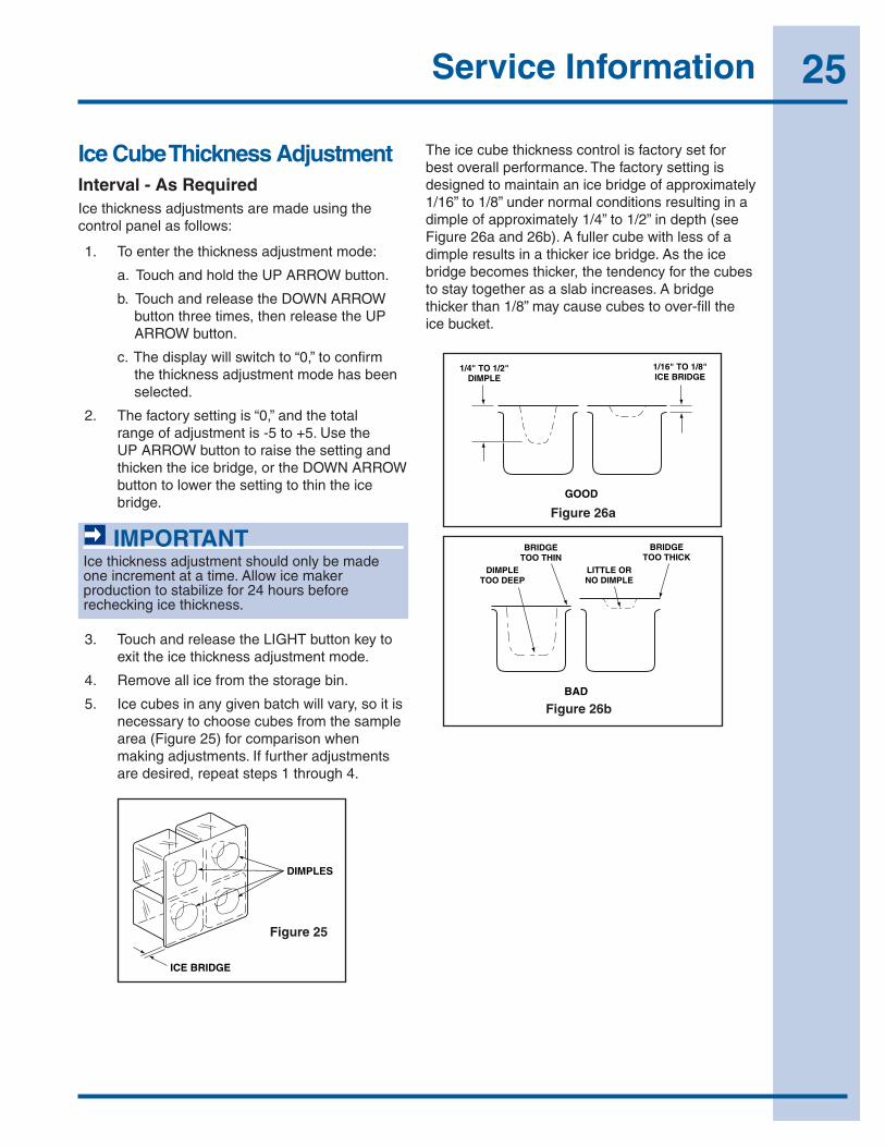
Ice Cube Thickness AdjustmentInterval - As RequiredIcethicknessadjustmentsaremadeusingthecontrolpanelasfollows:
1. Toenterthethicknessadjustmentmode:
a.TouchandholdtheUPARROWbutton.
b.TouchandreleasetheDOWNARROWbuttonthreetimes,thenreleasetheUPARROWbutton.
c.Thedisplaywillswitchto“0,”toconfirmthethicknessadjustmentmodehasbeenselected.
2. Thefactorysettingis“0,”andthetotalrangeofadjustmentis-5to+5.UsetheUPARROWbuttontoraisethesettingandthickentheicebridge,ortheDOWNARROWbuttontolowerthesettingtothintheicebridge.
IMPORTANTIcethicknessadjustmentshouldonlybemadeoneincrementatatime.Allowicemakerproductiontostabilizefor24hoursbeforerecheckingicethickness.
3. TouchandreleasetheLIGHTbuttonkeytoexittheicethicknessadjustmentmode.
4. Removeallicefromthestoragebin.
5. Icecubesinanygivenbatchwillvary,soitisnecessarytochoosecubesfromthesamplearea(Figure25)forcomparisonwhenmakingadjustments.Iffurtheradjustmentsaredesired,repeatsteps1through4.
DIMPLES
ICE BRIDGEICE001
Figure 25
Theicecubethicknesscontrolisfactorysetforbestoverallperformance.Thefactorysettingisdesignedtomaintainanicebridgeofapproximately1/16”to1/8”undernormalconditionsresultinginadimpleofapproximately1/4”to1/2”indepth(seeFigure26aand26b).Afullercubewithlessofadimpleresultsinathickericebridge.Astheicebridgebecomesthicker,thetendencyforthecubestostaytogetherasaslabincreases.Abridgethickerthan1/8”maycausecubestoover-filltheicebucket.
GOOD
BRIDGETOO THIN
BRIDGETOO THICK
DIMPLETOO DEEP
LITTLE ORNO DIMPLE
1/4" TO 1/2"DIMPLE
1/16" TO 1/8"ICE BRIDGE
BADICE002
Figure 26a
GOOD
BRIDGETOO THIN
BRIDGETOO THICK
DIMPLETOO DEEP
LITTLE ORNO DIMPLE
1/4" TO 1/2"DIMPLE
1/16" TO 1/8"ICE BRIDGE
BADICE002
Figure 26b
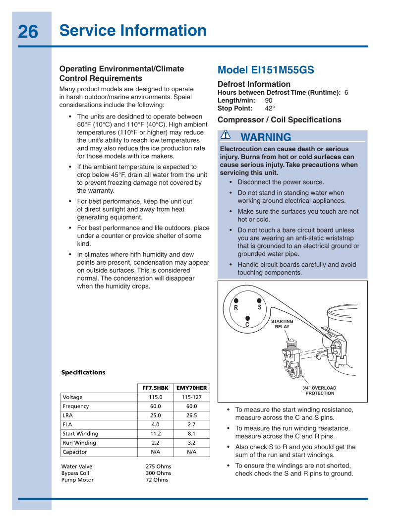
26 Service Information
Operating Environmental/Climate Control RequirementsManyproductmodelsaredesignedtooperateinharshoutdoor/marineenvironments.Speialconsiderationsincludethefollowing:
• Theunitsaredesidnedtooperatebetween50°F(10°C)and110°F(40°C).Highambienttemperatures(110°Forhigher)mayreducetheunit’sabilitytoreachlowtemperaturesandmayalsoreducetheiceproductionrateforthosemodelswithicemakers.
• Iftheambienttemperatureisexpectedtodropbelow45°F,drainallwaterfromtheunittopreventfreezingdamagenotcoveredbythewarranty.
• Forbestperformance,keeptheunitoutofdirectsunlightandawayfromheatgeneratingequipment.
• Forbestperformanceandlifeoutdoors,placeunderacounterorprovideshelterofsomekind.
• Inclimateswherehifhhumidityanddewpointsarepresent,condensationmayappearonoutsidesurfaces.Thisisconsiderednormal.Thecondensationwilldisappearwhenthehumiditydrops.
WARNINGElectrocution can cause death or serious injury. Burns from hot or cold surfaces can cause serious injuty. Take precautions when servicing this unit. • Disconnectthepowersource.
• Donotstandinstandingwaterwhenworkingaroundelectricalappliances.
• Makesurethesurfacesyoutoucharenothotorcold.
• Donottouchabarecircuitboardunlessyouarewearingananti-staticwriststrapthatisgroundedtoanelectricalgroundorgroundedwaterpipe.
• Handlecircuitboardscarefullyandavoidtouchingcomponents.
Model EI151M55GSDefrost InformationHours between Defrost Time (Runtime):6Length/min: 90Stop Point: 42°
Compressor / Coil Specifications
34
Model CLR2160
Compressor/Coil Specifications
DANGER
Electrocution can cause death or serious injury. Burns from hot or cold surfaces can cause serious injury. Take precautions when servicing this unit.
• Disconnect the power source.• Do not stand in standing water when working
around electrical appliances.• Make sure the surfaces you touch are not hot or
frozen.• Do not touch a bare circuit board unless you are
wearing an anti-static wriststrap that is grounded to an electrical ground or grounded water pipe.
• Handle circuit boards carefully and avoid touching components.
Figure 1
To measure the start winding resistance measure across the C and S pins.
To measure the run winding resistance measure across the C and R pins.
Also check S to R and you should get the sum of the run and start windings.
To ensure the windings are not shorted check the S and R to ground.
Specifications
Water Valve 275 OhmsBypass Coil 300 OhmsPump Motor 72 Ohms
C
SR
ULIN_0568_A
STARTINGRELAY
3/4" OVERLOAD PROTECTION
FF7.5HBK EMY70HER
Voltage 115.0 115-127
Frequency 60.0 60.0
LRA 25.0 26.5
FLA 4.0 2.7
Start Winding 11.2 8.1
Run Winding 2.2 3.2
Capacitor N/A N/A
• Tomeasurethestartwindingresistance,measureacrosstheCandSpins.
• Tomeasuretherunwindingresistance,measureacrosstheCandRpins.
• AlsocheckStoRandyoushouldgetthesumoftherunandstartwindings.
• Toensurethewindingsarenotshorted,checkchecktheSandRpinstoground.
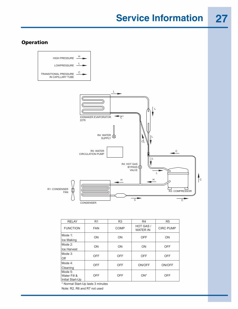
27Service Information
36
Model CLR2160
Operation
Figure 1
HIGH PRESSURE
LOWPRESSURE
TRANSITIONAL PRESSUREIN CAPILLARY TUBE
H
L
C
L
L
C
C
C
C
C
L
L
HH
C
L
ICEMAKER EVAPORATOR2276
R4: WATERSUPPLY
R5: WATERCIRCULATION PUMP
R4: HOT GASBYPASS
VALVE
R1: CONDENSERFAN
CONDENSER
R3: COMPRESSOR
RELAY R1 R3 R4 R5
FUNCTION FAN
ON
ON
OFF
OFF
OFF
ON
ON
OFF
OFF
OFF
OFF
ON
OFF
ON/OFF
ON*
ON
OFF
OFF
ON/OFF
OFF
COMP CIRC PUMPHOT GAS /WATER IN
Mode 1:Ice MakingMode 2:Ice HarvestMode 3:OffMode 4:CleaningMode 5:Water Fill &Initial Start-Up* Normal Start-Up lasts 3 minutesNote: R2, R6 and R7 not used
28 Service InformationModel CLR2160
37
Upon initial startup, this unit will enter mode number 5 which is a three-minute water fill regardless of the thermistor temperatures. This only occurs when the intial startup is caused by a power-up of the main board.
Following the three-minute water fill, the unit moves into mode 1 which is the freezing mode. In this mode the water is pumped from the sump trough over the ice maker grid by the circulation pump. This mode typically lasts 10-20 minutes and is regulated by the temperature of the thermistor mounted near the dryer (thermistor 4).
At the conclusion of the freeze cycle the unit will enter mode 2 which is the ice harvest. This harvest can last up to three minutes. During this mode the water trough also refills.
Before the next cycle begins, the custom electronic board determines whether the bin is full. A temperature below 34°F, or a temperature below 35°F for at least one hour will stop the unit from producing ice. The ice-making will always stop at the conclusion of a harvest cycle. It will never stop in the middle of a cycle.
The custom electronic board continuously monitors the optional P60 pump to ensure the drain line is not becoming restricted. In the event of a drain line obstruction, the display interface will show “P1.” If the drain remains restricted the unit will stop ice production until the drain clears. In the event of a partially restricted drain, reduced ice rate will be noticed as the unit continuously turns on and off to eliminate any chances of overfilling the unit with water. If no pump is used the pink jumper needs to be connected to the power cord in its place.
A cleaning mode is available through the user interface by using the key sequence described in the Controls Section. The cleaning mode lasts about 45 minutes, at which point the unit will sit idle for another 15 minutes. During this time the display will show “CL.” At the conclusion of the cycle the unit will automatically turn back on.
Thermistor Outage:
In the event that a thermistor fails, the unit will stop all functions and display “ER” on the user interface. The exact error can be accessed via the service mode.
Service:
The CLR2160 model uses four relays and two thermistors. There is a variety of built-in servicing features to aid in diagnosing the root problem associated with a unit.
To check to see which relays are currently operating, hold the COLDER key and press the ON/OFF key three times. When entering the sequence, keep the COLDER key pressed until you completely release the ON/OFF key for the third time. The display will cycle through a series of numbers to tell which relays are energized. For example, if the unit was in ice-making mode the display would show 11 20 31 40 51 60 70. The first number is the relay number. In the second number, “1” means on and “0”
means off. The relay information can be found in the Control Section.
Each relay can also be turned on and off individually to determine whether or not the board and component are operating. If a board is suspected of not operating correctly you can run through this sequence to ensure each component is turning on and off through the board correctly. Go into service mode and choose option #22. This will cycle every relay on and off showing 10 11 20 21 …. If a component fails to turn on when the relay does, you can verify if there is voltage present by using a voltmeter to check the board output.
To view the actual thermistor readings, hold the WARMER and COLDER keys for about five seconds. The display will cycle through the three thermistors and their temperatures. If a thermistor is unused in a unit it will show a “0” reading. The CLR2160 uses thermistors 2 and 4. For thermistor 4 the display will only show up to “99.” In the event the temperature is higher than this the display will show a flashing “99.”
Troubleshooting:
Display shows ER or P1
E1, E2, E9 Bad thermistor errors. Replace thermistor. Check for thermistor errors by accessing “View thermistor # status (19, 20, or 21).” If the error code is repeated, the thermistor is open or shorted. If a temperature is displayed, the thermistor is not defective.
P1 Pump circuit is detecting a drain problem. Consult a plumber to resolve the issue. If unit does not have a P60 installed, then the jumper wire is missing in place of the pump.
Any other error messages will not affect the operation of the CLR2160 model.
After checking the errors be sure to clear the error log by performing service option 12.
No ice
Check the ice bin temperature. If the temperature is in the 34-35°F range, the unit is shut down due to low temperature inside. This could be caused by low ambient temperatures or running the unit without a water supply attached.
If the ice bin temperature is above 35°F, the unit should be producing ice. Check to ensure the water trough is full and the pump is operating. If the components are not operating, see the service section above.
Too much ice
Ensure there is Permagum around the thermistor hole. If there is, proceed to the next step.
The control board is equipped with an adjustment to adjust the level of ice in the bin for customer preference or when used in abnormal installations. With ice stacked to the desired level, check the bin temperature by holding
EIMP60
E151M
E151M
E151M

29Service Information
38
Model CLR2160
WARMER and COLDER for five seconds. We’ll assume the display showed 38°F for this example. Go to service mode #24 and adjust the setting to that number. This will allow the bin to shut off at this ice level. This temperature needs to be checked after the door has been closed for at least 10 minutes in order for the thermistor temperature to stabilize.
Too little ice
If this is a recurring issue, try adjusting service option #24 warmer in 1 or 2° increments until the desired level of ice is achieved.
Ice not sized to customer satisfaction
The thickness of the cubes can be adjusted per the ice thickness section of the manual.
Noise
Some noise from this unit is normal. You may hear the sound of ice dropping into the bin, especially when it is empty. The harvesting processes involves flowing refrigerant and water through valves which may produce a rushing type sound during the harvest. The fan and compressor will produce a continuous low motor noise. If installed, the P60 pump will produce noise at regular intervals as it empties water from the unit. If any of these is objectionable, the unit has an Office mode which can be entered for three hours at a time. During this mode the unit will not produce ice; however, the drain pump will continue to operate.
No water in trough
Ensure the standpipe is fully inserted into the trough.
Check the water valve to see if it is filling the unit.
Watch the water flow over the mold to see if excess water is being splashed out of the trough. This could be the result of improper leveling.
Ice does not release from evaporator
This could be caused by improper leveling or the unit is in need of cleaning.
Poor ice quality
This can be caused by poor incoming water quality. The CLR2160 is designed to produce clear ice in most water; however, abnormal water conditions may result in the need for further filtering.
Water in ice bin
A defect in the drain from the unit will cause water to stop draining from the unit.
Display is showing something other than “Ice,” “ER” or “CL.”
Push one of the keys to see if the display is reset.
Turn unit on and off via the display pad.
Unplug unit, wait one minute and plug back in. If any of these steps return the unit to operation the unit was probably accidently entered into a service mode.
Display is showing a random snaking of characters or a degree symbol is flashing.
The unit is in a special showroom mode. Hold the COLDER key and press the LIGHT key three times to exit.
Display not illuminating but unit operating
First try to plug and unplug the unit. If the display still does not illuminate, there is a four-wire pin connector running from the main board in the base to the display board. One of the wires is disconnected or damaged.
Unit is not operating—no cooling—no fans.
Unplug unit and plug back in. If main board beeps when plugging in the unit then this is most likely a system problem not a board issue.
If board does not beep when plugging in the unit, check the power supply to ensure the outlet is working. Also, check the fuse on the circuit board.
EI51M

30 Service InformationModel CLR2160
39
Wiring Diagram
Ice Production Rates
NOTE: These characteristics will vary depending on operating conditions, condenser cleanliness, installation and application.
ULIN_0262_A
Ambient Temp/Water Temp °F Approximate Ice Production (lbs/day)
50/50 60
60/50 60
70/50 58
80/50 54
90/70 47
100/70 40
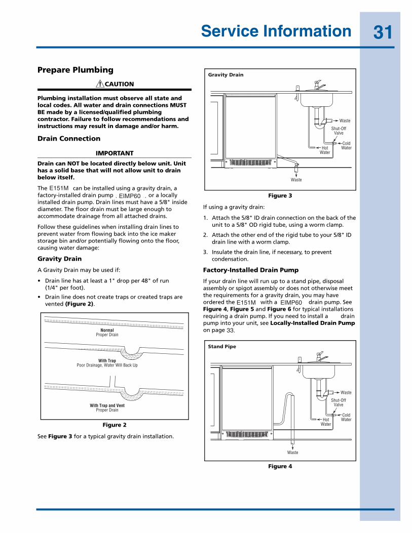
31Service Information
40
Model CLR2160
Prepare Plumbing
CAUTION
Plumbing installation must observe all state and local codes. All water and drain connections MUST BE made by a licensed/qualified plumbing contractor. Failure to follow recommendations and instructions may result in damage and/or harm.
Drain Connection
IMPORTANTIMPORTANT
Drain can NOT be located directly below unit. Unit has a solid base that will not allow unit to drain below itself.
The CLR2160 can be installed using a gravity drain, a factory-installed drain pump (U-Line P60) or a locally installed drain pump. Drain lines must have a 5/8" inside diameter. The floor drain must be large enough to accommodate drainage from all attached drains.
Follow these guidelines when installing drain lines to prevent water from flowing back into the ice maker storage bin and/or potentially flowing onto the floor, causing water damage:
Gravity Drain
A Gravity Drain may be used if:
• Drain line has at least a 1" drop per 48" of run (1/4" per foot).
• Drain line does not create traps or created traps are vented (Figure 2).
Figure 2
See Figure 3 for a typical gravity drain installation.
Figure 3
If using a gravity drain:
1. Attach the 5/8" ID drain connection on the back of the unit to a 5/8" OD rigid tube, using a worm clamp.
2. Attach the other end of the rigid tube to your 5/8" ID drain line with a worm clamp.
3. Insulate the drain line, if necessary, to prevent condensation.
Factory-Installed Drain Pump
If your drain line will run up to a stand pipe, disposal assembly or spigot assembly or does not otherwise meet the requirements for a gravity drain, you may have ordered the CLR2160 with a U-Line P60 drain pump. See Figure 4, Figure 5 and Figure 6 for typical installations requiring a drain pump. If you need to install a P60 drain pump into your unit, see Locally-Installed Drain Pump on page 42.
Figure 4
NormalProper Drain
With TrapPoor Drainage, Water Will Back Up
With Trap and VentProper Drain
ULIN_0569_A
Waste
Waste
ColdWater
Shut-OffValve
HotWater
Gravity Drain
ULIN_0570_A
ColdWaterHot
Water
Waste
Waste
Shut-OffValve
Stand Pipe
ULIN_0571_A
E151M
E151M
EIMP60
EIMP60
33.

32 Service InformationModel CLR2160
41
Figure 5
Figure 6
IMPORTANTIMPORTANT
Before installing your U-Line CLR2160 with factory- installed U-Line P60 pump, it is extremely important to check and test all hose connections at the drain pump. There is a possibility that hose connections may have loosened during shipment.
WARNING
To prevent accidental electrocution, make certain that the floor surfaces surrounding the unit are dry whenever power is removed from, or applied to, the unit.
To check and test hose connections:
1. Make certain the unit is not plugged into an electrical outlet.
2. Carefully push the power cord grommet through the hole in the back panel (Figure 7).
Figure 7
3. Remove 12 screws and back panel.
WARNING
Back panel serves as a guard. DO NOT put your hands inside the ice maker cabinet or attempt to touch any components except the discharge tube during testing. Failure to follow this warning could result in serious personal injury or death.
4. Check that the clamps and hose connections are tight at the following areas (Figure 8):
• Discharge tube (A)
• Drain tube (B)
• Vent tube (C)
Figure 8
5. Place a suitable container beneath the pump’s discharge tube. (The bucket must be able to hold a minimum of one gallon.)
6. Plug the ice maker power cord into a properly grounded, polarized electrical outlet.
7. Verify pump operation by pouring one gallon of water into the ice storage bin of the ice maker. The pump should energize and pump the water into the container.
8. At this time, verify that all tube and clamp connections are tight and leak free.
Air Gap(Optional Hook-Up)
ColdWaterHot
Water
Waste
Shut-OffValve
Disposal Assembly
ULIN_0572_A
Waste
ColdWater
Shut-OffValve
HotWater
Air Gap(Optional Hook-Up)
Spigot Assembly
ULIN_0573_A
PowerCord
Grommet
DrainFitting
BackPanel
WaterConnection
Screws
ULIN_0574_A
Back View Side View
BB
A
CC
ULIN_0575_A
pump,EIMP60E151M
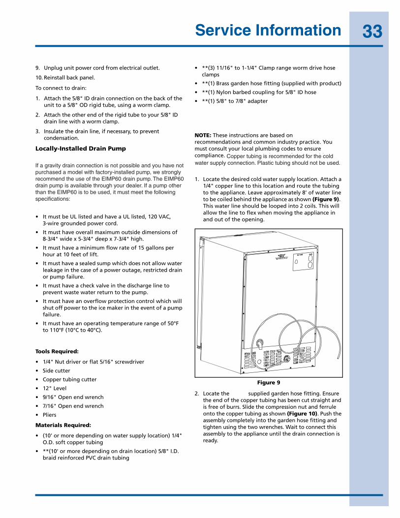
33Service Information
42
Model CLR2160
9. Unplug unit power cord from electrical outlet.
10. Reinstall back panel.
To connect to drain:
1. Attach the 5/8" ID drain connection on the back of the unit to a 5/8" OD rigid tube, using a worm clamp.
2. Attach the other end of the rigid tube to your 5/8" ID drain line with a worm clamp.
3. Insulate the drain line, if necessary, to prevent condensation.
Locally-Installed Drain Pump
If a gravity drain connection is not possible, and you have not purchased the CLR2160 with factory-installed pump, we strongly recommend the use of the U-Line P60 drain pump. The U-Line P60 drain pump is available through your dealer, or direct from U-Line with complete installation instructions. If a pump other than the U-Line P60 drain pump is to be used, it must meet the following specifications:
• It must be UL listed and have a UL listed, 120 VAC, 3-wire grounded power cord.
• It must have overall maximum outside dimensions of 8-3/4" wide x 5-3/4" deep x 7-3/4" high.
• It must have a minimum flow rate of 15 gallons per hour at 10 feet of lift.
• It must have a sealed sump which does not allow water leakage in the case of a power outage, restricted drain or pump failure.
• It must have a check valve in the discharge line to prevent waste water return to the pump.
• It must have an overflow protection control which will shut off power to the ice maker in the event of a pump failure.
• It must have an operating temperature range of 50°F to 110°F (10°C to 40°C).
U-CLR Drain Kit (Available for Purchase)
Tools Required:
• 1/4" Nut driver or flat 5/16" screwdriver
• Side cutter
• Copper tubing cutter
• 12" Level
• 9/16" Open end wrench
• 7/16" Open end wrench
• Pliers
Materials Required:
• (10' or more depending on water supply location) 1/4" O.D. soft copper tubing
• **(10' or more depending on drain location) 5/8" I.D. braid reinforced PVC drain tubing
• **(3) 11/16" to 1-1/4" Clamp range worm drive hose clamps
• **(1) Brass garden hose fitting (supplied with product)
• **(1) Nylon barbed coupling for 5/8" ID hose
• **(1) 5/8" to 7/8" adapter
** Depending on your model, your unit may have been packaged with these items. If you need to order these items, please contact U-Line and order Part # U-CLRDRAINKIT.
NOTE: These instructions are based on the U-Line recommendations and common industry practice. You must consult your local plumbing codes to ensure compliance. U-Line requires the use of copper cold water supply connection tubing. Plastic tubing should not be used.
1. Locate the desired cold water supply location. Attach a 1/4" copper line to this location and route the tubing to the appliance. Leave approximately 8' of water line to be coiled behind the appliance as shown (Figure 9). This water line should be looped into 2 coils. This will allow the line to flex when moving the appliance in and out of the opening.
Figure 9
2. Locate the U-Line supplied garden hose fitting. Ensure the end of the copper tubing has been cut straight and is free of burrs. Slide the compression nut and ferrule onto the copper tubing as shown (Figure 10). Push the assembly completely into the garden hose fitting and tighten using the two wrenches. Wait to connect this assembly to the appliance until the drain connection is ready.
ULIN_S_165
EIMP60EIMP60
Coppertubingisrecommendedforthecoldwatersupplyconnection.Plastictubingshouldnotbeused.amodelIfagravitydrainconnectionisnotpossibleandyouhavenot
purchasedamodelwithfactory-installedpump,westronglyrecommendtheuseoftheEIMP60drainpump.TheEIMP60drainpumpisavailablethroughyourdealer.IfapumpotherthantheEIMP60istobeused,itmustmeetthefollowingspecifications:
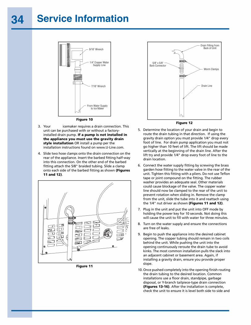
34 Service InformationModel CLR2160
43
Figure 10
3. Your U-Line icemaker requires a drain connection. This unit can be purchased with or without a factory-installed drain pump. If a pump is not installed in the appliance you must use the gravity drain style installation OR install a pump per the installation instructions found on www.U-Line.com.
4. Slide two hose clamps onto the drain connection on the rear of the appliance. Insert the barbed fitting half-way into this connection. On the other end of the barbed fitting attach the 5/8" braided tubing. Slide a clamp onto each side of the barbed fitting as shown (Figures 11 and 12).
Figure 11
Figure 12
5. Determine the location of your drain and begin to route the drain tubing in that direction. If using the gravity drain option you must provide 1/4" drop every foot of line. For drain pump application you must not go higher than 10 feet of lift. The lift should be made vertically at the beginning of the drain line. After the lift try and provide 1/4" drop every foot of line to the drain location.
6. Connect the water supply fitting by screwing the brass garden hose fitting to the water valve in the rear of the unit. Tighten this fitting with a pliers. Do not use Teflon tape or joint compound on the fitting. The rubber washer provides an adequate seal. Other materials could cause blockage of the valve. The copper water line should now be clamped to the rear of the unit to prevent rotation when sliding in. Remove the clamp from the unit, slide the tube into it and reattach using the 1/4" nut driver as shown (Figures 11 and 12).
7. Plug in the unit and put the unit into OFF mode by holding the power key for 10 seconds. Not doing this will cause the unit to fill with water for three minutes.
8. Turn on the water supply and ensure the connections are free of leaks.
9. Begin to push the appliance into the desired cabinet opening. The copper tubing should remain in two coils behind the unit. While pushing the unit into the opening continuously reroute the drain tube to avoid kinks. The most common installation pulls the slack into an adjacent cabinet or basement area. Again, if installing a gravity drain, ensure you provide proper slope.
10. Once pushed completely into the opening finish routing the drain tubing to the desired location. Common installations use a floor drain, standpipe, garbage disposal, or Y-branch tailpiece-type drain connection (Figures 13-16). After the installation is complete, check the unit to ensure it is level both side to side and
9/16" Wrench
1/4" Copper WaterSupply Line
7/16" Wrench
From Water Supplyto Ice Maker
ULIN_S_0168_A
ULIN_S_0166b1_A
Drain Fitting fromBack of Unit
Worm Clamps
Drain Line
5/8" x 5/8"Barb Connector
ULIN_S_0166b2_A
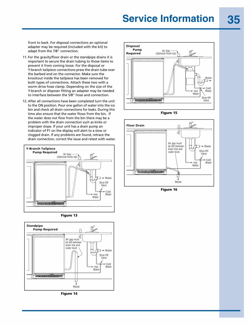
35Service Information
44
Model CLR2160
front to back. For disposal connections an optional adapter may be required (included with the kit) to adapt from the 7/8" connection.
11. For the gravity/floor drain or the standpipe drains it is important to secure the drain tubing to those items to prevent it from coming loose. For the disposal or Y-branch tailpiece connections press the drain tube over the barbed end on the connector. Make sure the knockout inside the tailpiece has been removed for both types of connections. Attach these two with a worm drive hose clamp. Depending on the size of the Y-branch or disposer fitting an adapter may be needed to interface between the 5/8" hose and connection.
12. After all connections have been completed turn the unit to the ON position. Pour one gallon of water into the ice bin and check all drain connections for leaks. During this time also ensure that the water flows from the bin. If the water does not flow from the bin there may be a problem with the drain connection such as kinks or improper slope. If your unit has a drain pump an indicator of P1 on the display will alert to a slow or clogged drain. If any problems are found, retrace the drain connection, correct the issue and retest with water.
Figure 13
Figure 14
Figure 15
Figure 16
Waste
Cold Water
Shut-Off Valve
Hot Water
Air Gap (Optional Hook-Up)
Y-Branch TailpieceP60 Pump Required
ULIN_0600a_A
Cold Water Hot
Water
Waste
Waste
Shut-Off Valve
StandpipeP60 Pump Required
Air gap must be left betweendrain line andwater level.
ULIN_0598a_A
Air Gap (Optional Hook-Up)
Cold Water Hot
Water
Waste
Shut-Off Valve
DisposalP60 PumpRequired
ULIN_0599a_A
Waste
Waste
Cold Water
Shut-Off Valve
Hot Water
Floor Drain
Air gap must be left betweendrain line andwater level.
ULIN_0597a_A
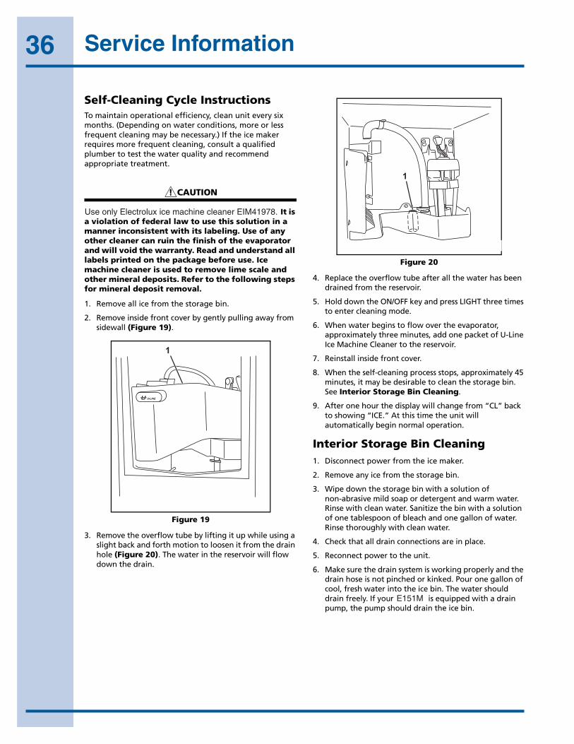
36 Service Information
46
Model CLR2160
Self-Cleaning Cycle InstructionsTo maintain operational efficiency, clean unit every six months. (Depending on water conditions, more or less frequent cleaning may be necessary.) If the ice maker requires more frequent cleaning, consult a qualified plumber to test the water quality and recommend appropriate treatment. Use only U-Line Ice Machine Cleaner (P/N 41978).
CAUTION
Use only U-Line Ice Machine Cleaner (P/N 41978). It is a violation of federal law to use this solution in a manner inconsistent with its labeling. Use of any other cleaner can ruin the finish of the evaporator and will void the warranty. Read and understand all labels printed on the package before use. Ice machine cleaner is used to remove lime scale and other mineral deposits. Refer to the following steps for mineral deposit removal.
1. Remove all ice from the storage bin.
2. Remove inside front cover by gently pulling away from sidewall (Figure 19).
Figure 19
3. Remove the overflow tube by lifting it up while using a slight back and forth motion to loosen it from the drain hole (Figure 20). The water in the reservoir will flow down the drain.
Figure 20
4. Replace the overflow tube after all the water has been drained from the reservoir.
5. Hold down the ON/OFF key and press LIGHT three times to enter cleaning mode.
6. When water begins to flow over the evaporator, approximately three minutes, add one packet of U-Line Ice Machine Cleaner to the reservoir.
7. Reinstall inside front cover.
8. When the self-cleaning process stops, approximately 45 minutes, it may be desirable to clean the storage bin. See Interior Storage Bin Cleaning.
9. After one hour the display will change from “CL” back to showing “ICE.” At this time the unit will automatically begin normal operation.
Interior Storage Bin Cleaning1. Disconnect power from the ice maker.
2. Remove any ice from the storage bin.
3. Wipe down the storage bin with a solution of non-abrasive mild soap or detergent and warm water. Rinse with clean water. Sanitize the bin with a solution of one tablespoon of bleach and one gallon of water. Rinse thoroughly with clean water.
4. Check that all drain connections are in place.
5. Reconnect power to the unit.
6. Make sure the drain system is working properly and the drain hose is not pinched or kinked. Pour one gallon of cool, fresh water into the ice bin. The water should drain freely. If your CLR2160 is equipped with a drain pump, the pump should drain the ice bin.
1
ULIN_0059_A
1
ULIN_0060_A
UseonlyElectroluxicemachinecleanerEIM41978.
E151M

37Parts InformationModel CLR2160
47
CLR2160
Figure 21
8 Parts Section
Item Description Figure Page
2 INTERIOR, CLR2160 24 51
3 HINGE COMP 25 52
4 DOOR COMPONENTS 25 52
5 BASE ASSY, CLR2160 26 54
6 CONTROL COMPONENTS 22 48
7 BACK PANEL, CLR2160 23 50
8 GRILLE ASSY 25 52
11 WASTE WATER PUMP ASSY 27 55
DRAIN INSTALLATION KIT (U-CLRDRAINKIT) (not shown)
ULIN_S_0047_A
7 63
2
4
8
11
5
EI151M55GS Parts Section
Model CLR2160
47
CLR2160
Figure 21
8 Parts Section
Item Description Figure Page
2 INTERIOR, CLR2160 24 51
3 HINGE COMP 25 52
4 DOOR COMPONENTS 25 52
5 BASE ASSY, CLR2160 26 54
6 CONTROL COMPONENTS 22 48
7 BACK PANEL, CLR2160 23 50
8 GRILLE ASSY 25 52
11 WASTE WATER PUMP ASSY 27 55
DRAIN INSTALLATION KIT (U-CLRDRAINKIT) (not shown)
ULIN_S_0047_A
7 63
2
4
8
11
5
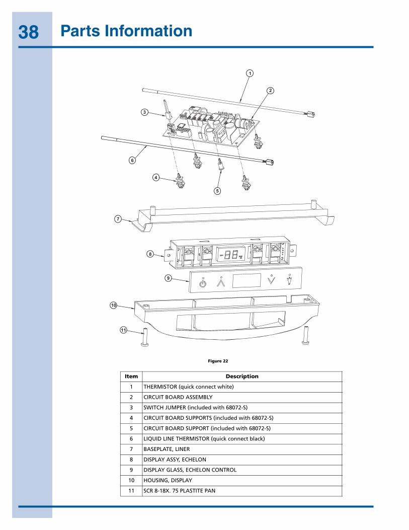
38 Parts Information
48
Model CLR2160
Figure 22
ULIN_S_0032b_C
2
5
4
3
1
11
10
9
8
7
6
Model CLR2160
49
Item Description Part Number
1 THERMISTOR (quick connect white) 68073
2 CIRCUIT BOARD ASSEMBLY 68072-S
3 SWITCH JUMPER (included with 68072-S) 68080
4 CIRCUIT BOARD SUPPORTS (included with 68072-S) 41992
5 CIRCUIT BOARD SUPPORT (included with 68072-S) 41993
6 LIQUID LINE THERMISTOR (quick connect black) 68076
7 BASEPLATE, LINER 26086
8 DISPLAY ASSY, ECHELON 68074
9 DISPLAY GLASS, ECHELON CONTROL 68059-01
10 HOUSING, DISPLAY 26089
11 SCR 8-18X. 75 PLASTITE PAN 42162
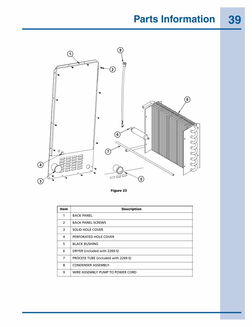
39Parts Information
50
Model CLR2160
Figure 23
Item Description Part Number
1 BACK PANEL 11964-02
2 BACK PANEL SCREWS 41342
3 SOLID HOLE COVER 42125
4 PERFORATED HOLE COVER N/A
5 BLACK BUSHING 41955
6 DRYER (included with 2269-S) 2850
7 PROCESS TUBE (included with 2269-S) 2819
8 CONDENSER ASSEMBLY 2269-S
9 WIRE ASSEMBLY PUMP TO POWER CORD 2892-02
ULIN_S_0085c_A5
4
3
1
2
9
6
7
8
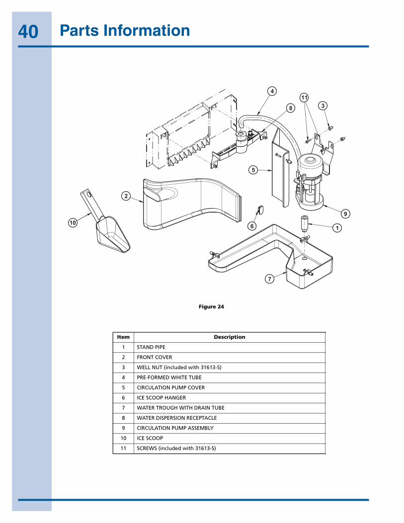
40 Parts Information
Model CLR2160
51
Figure 24
ULIN_S_0075_A
10
4
8
2
5
6
7
1
9
311
Item Description Part Number
1 STAND PIPE 31619
2 FRONT COVER 11868
3 WELL NUT (included with 31613-S) 41979
4 PRE-FORMED WHITE TUBE 31615-S
5 CIRCULATION PUMP COVER 11893
6 ICE SCOOP HANGER 42011
7 WATER TROUGH WITH DRAIN TUBE 11813
8 WATER DISPERSION RECEPTACLE 11812-S
9 CIRCULATION PUMP ASSEMBLY 31613-S
10 ICE SCOOP 31614
11 SCREWS (included with 31613-S) 41981
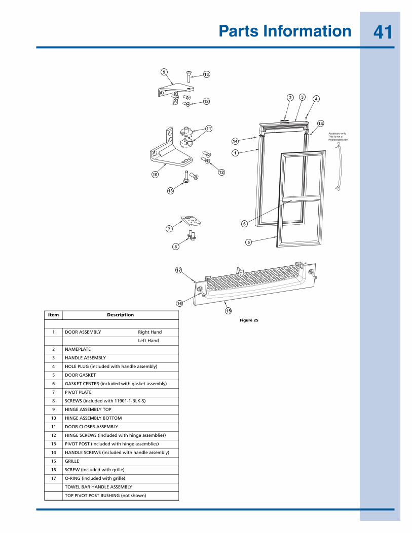
41Parts Information
52
Model CLR2160
Figure 25
ULIN_S_0049a_A
Accessory onlyThis is not aReplaceable part
17
1615
9 13
12
11
14
14
1
432
12
5
6
13
10
7
8
Model CLR2160
53
Item Description Part Number
Black White Stainless Steel
1 DOOR ASSEMBLY Right Hand 80-17071-01 80-17071-02 80-17071-03
Left Hand 80-17071-13
2 NAMEPLATE 23025 23025 23025
3 HANDLE ASSEMBLY 26071-01-S 26071-02-S N/A
4 HOLE PLUG (included with handle assembly) 42173-BLK 42173-NAT N/A
5 DOOR GASKET 12094-04-S 12094-06-S 12094-05-S
6 GASKET CENTER (included with gasket assembly) 12095-04 12095-06 12095-05
7 PIVOT PLATE 11901-1-BLK-S 11901-1-BLK-S 11994-BLK-S
8 SCREWS (included with 11901-1-BLK-S) 42161-ZP 42161-ZP 42161-ZP
9 HINGE ASSEMBLY TOP 11898-S-BLK 11898-S-KIT 11995-S-SS
10 HINGE ASSEMBLY BOTTOM 11899-S-BLK 11899-S-KIT 11996-S-SS
11 DOOR CLOSER ASSEMBLY 31673-S 31673-S 31673-S
12 HINGE SCREWS (included with hinge assemblies) 42101-BLK 42101-ZP 42101-SS
13 PIVOT POST (included with hinge assemblies) 42096 42096 42096
14 HANDLE SCREWS (included with handle assembly) 41604 41725 N/A
15 GRILLE 80-29012-01 80-29012-02 80-29012-03
16 SCREW (included with grille) 20033-BLK 20033-ZP 20033-ZP
17 O-RING (included with grille) 21010 21010 21010
TOWEL BAR HANDLE ASSEMBLY (this is not a replaceable part) 18033-S
TOP PIVOT POST BUSHING (not shown) N/A N/A 12091
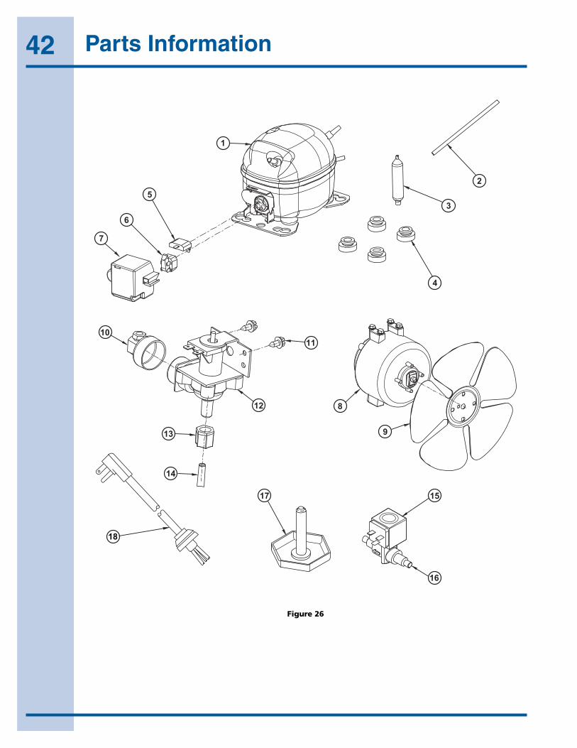
42 Parts Information
54
Model CLR2160
Figure 26
ULIN_S_0064b_A
5 2
3
4
1
6
7
10 11
8
9
12
13
14
15
16
17
18
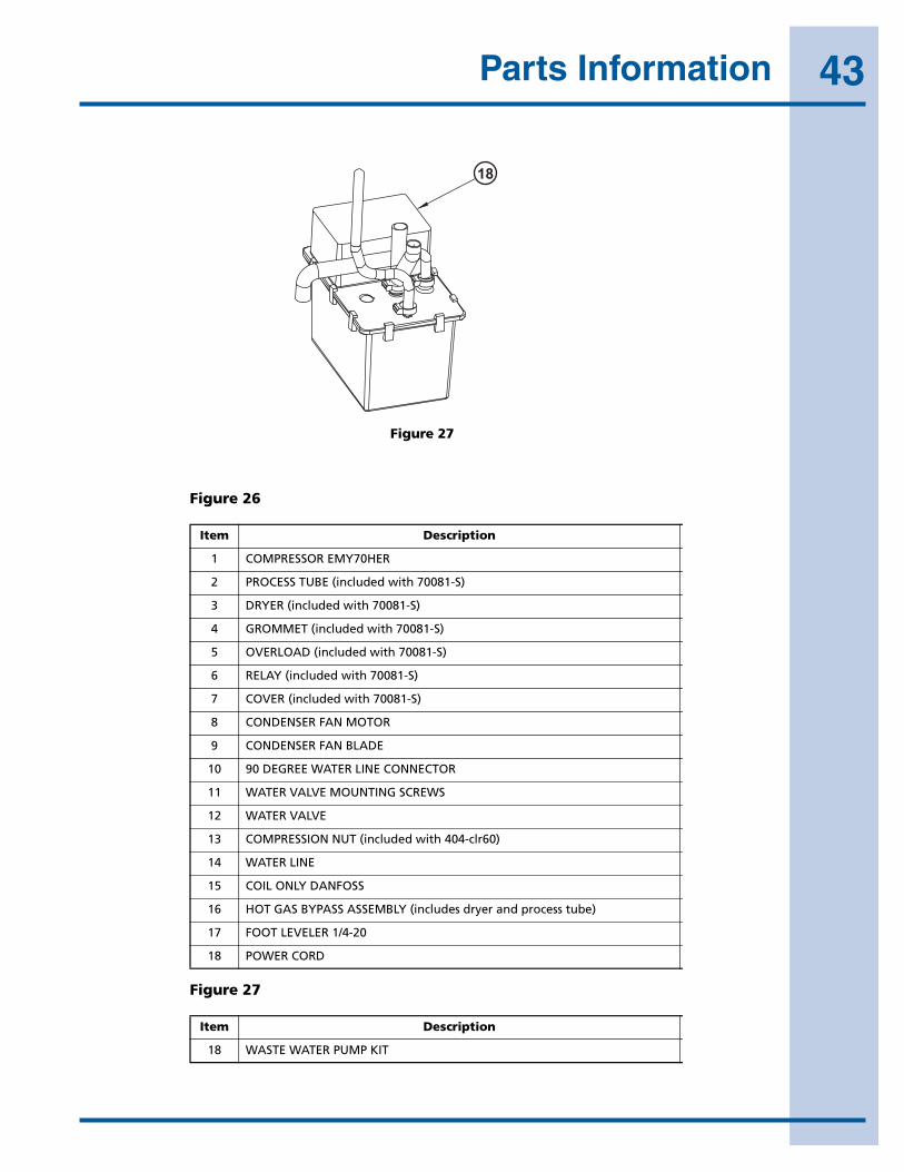
43Parts InformationModel CLR2160
55
Figure 27
Figure 26
Figure 27
ULIN-P60-00_A
18
Item Description Part Number
1 COMPRESSOR EMY70HER 70081-S
2 PROCESS TUBE (included with 70081-S) 2819
3 DRYER (included with 70081-S) 2693
4 GROMMET (included with 70081-S) 31021
5 OVERLOAD (included with 70081-S) 71027
6 RELAY (included with 70081-S) 71028
7 COVER (included with 70081-S) 70081-CAP
8 CONDENSER FAN MOTOR 5300
9 CONDENSER FAN BLADE 5303
10 90 DEGREE WATER LINE CONNECTOR 41826
11 WATER VALVE MOUNTING SCREWS 42114
12 WATER VALVE 2716-1
13 COMPRESSION NUT (included with 404-clr60) 41254
14 WATER LINE 404-CLR60
15 COIL ONLY DANFOSS 73002-2
16 HOT GAS BYPASS ASSEMBLY (includes dryer and process tube) 73002-1-S
17 FOOT LEVELER 1/4-20 41319
18 POWER CORD 2949
Item Description Part Number
18 WASTE WATER PUMP KIT P-60
Model CLR2160
55
Figure 27
Figure 26
Figure 27
ULIN-P60-00_A
18
Item Description Part Number
1 COMPRESSOR EMY70HER 70081-S
2 PROCESS TUBE (included with 70081-S) 2819
3 DRYER (included with 70081-S) 2693
4 GROMMET (included with 70081-S) 31021
5 OVERLOAD (included with 70081-S) 71027
6 RELAY (included with 70081-S) 71028
7 COVER (included with 70081-S) 70081-CAP
8 CONDENSER FAN MOTOR 5300
9 CONDENSER FAN BLADE 5303
10 90 DEGREE WATER LINE CONNECTOR 41826
11 WATER VALVE MOUNTING SCREWS 42114
12 WATER VALVE 2716-1
13 COMPRESSION NUT (included with 404-clr60) 41254
14 WATER LINE 404-CLR60
15 COIL ONLY DANFOSS 73002-2
16 HOT GAS BYPASS ASSEMBLY (includes dryer and process tube) 73002-1-S
17 FOOT LEVELER 1/4-20 41319
18 POWER CORD 2949
Item Description Part Number
18 WASTE WATER PUMP KIT P-60
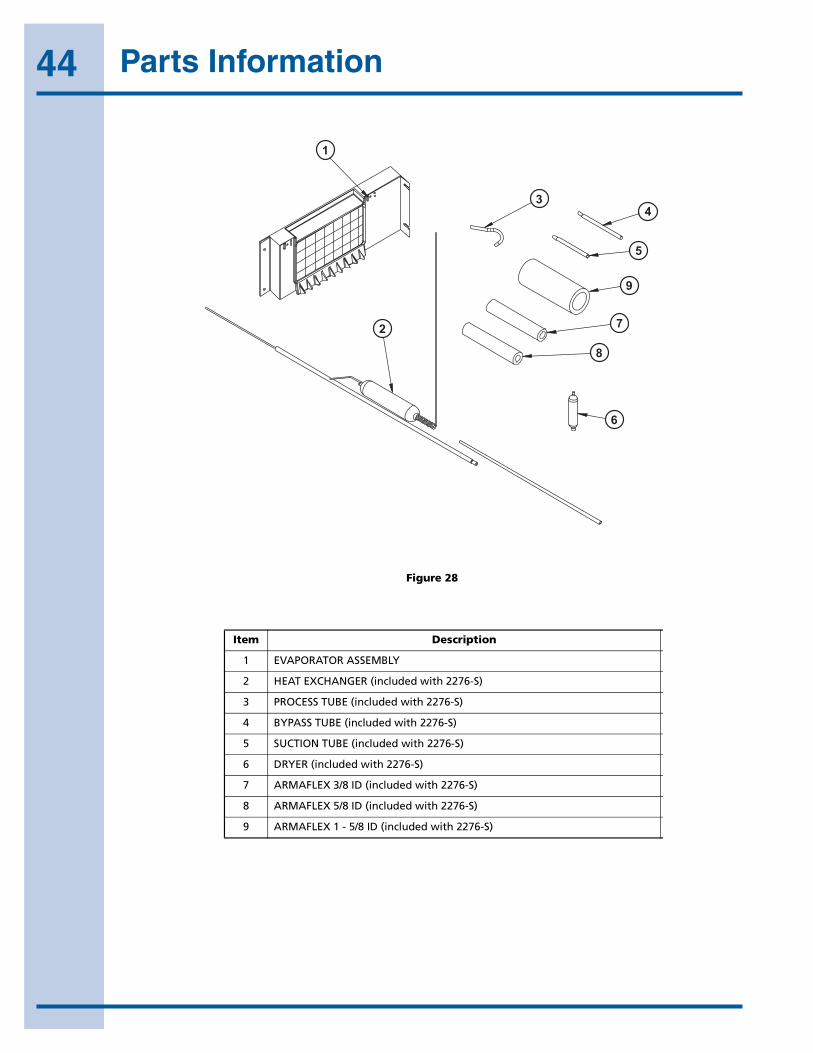
44 Parts Information
56
Model CLR2160
Figure 28
Item Description Part Number
1 EVAPORATOR ASSEMBLY 2276-S
2 HEAT EXCHANGER (included with 2276-S) 2725-S
3 PROCESS TUBE (included with 2276-S) 2819
4 BYPASS TUBE (included with 2276-S) 2836
5 SUCTION TUBE (included with 2276-S) 2837
6 DRYER (included with 2276-S) 2850
7 ARMAFLEX 3/8 ID (included with 2276-S) 31154
8 ARMAFLEX 5/8 ID (included with 2276-S) 31410
9 ARMAFLEX 1 - 5/8 ID (included with 2276-S) 31636
1
34
5
9
7
8
6
2
ULIN_S_0077_A

45Customer Call Guide
Concern Response
The unit is not cold enough! (All models)
Areyoufamiliarwiththefactorytemperaturespecificationsforyourunit?Manyfactorscancausethesetemperaturestovary;ambienttemperature,application,amountofuse(numberoftimesandlengthoftimethedoorordrawersareopenedorclosed),etc.
Isthedoorordrawerssealingproperly?Ifthedoorordrawerisnotsealedproperly,itallowsheatintheunit.
Hasthedoorordrawersbeenleftopen?
Isthecondenserclean?
Istheunitbehindcloseddoorsortheventrestricted?Thefrontgrillemustbefreeofobstruction.
Istheunitinanapplicationofheavyusage?Heavyusageorhighambienttemperaturewillcauseaunittofrostup.
Didyoutryadjustingthetemperaturetoacolderlevel/Besuretoallow24hoursbetweentemperaturecontroladjustments.
Temperature is too cold! (All models)
Checkactualtemperatureversussetpoint.
The unit is frosting up! (All models)
Areyoufamiliarwiththedefrosttechnologyofyourunit?
Isthedoorordrawerssealingproperly?Ifthedoorordrawerisnotsealedproperly,itallowsheat/humidityintotheunit.
Hasthedoorordrawersbeenleftopen?
Istheunitinanapplicationofheavyusage?Heavyusageorhighambienttemperaturewillcauseaunittofrostup.
Water is leaking out of the unit!
Haveyoucheckedthewaterconnectiontotheunit?Thewarrantydoesnotcoverinstallationadjustments.
No ice or not enough ice! (All models)
Areyouawareofthefactoryspecificationsforiceproduction.
Isthedoorordrawerssealingproperly?
Hastheicemakerbeenturnedoffatthedisplay?
My cubes are wet! Thestoragebinthatholdstheiceisnotrefrigerated.Thecubesinthebinareslowlymeltingdown.Thebinwillmaintainatemperatureof32°Fto34°F.
The floor is very wet if front of the unit.
Theunitisdesignedforabuilt-inapplication,sowarmairwillventthroughthefrontgrille,belowthedoor.Thereisasafetyfeaturebuiltintothecontrolboardthatwillshutdowntheunitifthewarmaircan’tventorisrestricted.
No ice, but water pours into the trough and down into the drain.
Thestandpipeneedstobeinsertedintothedrainholeofthewatertroughtomaintainproperlevelofwaterinsidethetrough
Thewarrantydoesnotcovercustomereducationcalls.Ithasbeenreportedthatashighas50%ofallservicecallsperformedarecustomereducationcalls.Thefollowingguidethatbeendevelopedtohelpanswerfrequentlyaskedquestions.Itcanbeusedbypersonsschedulingservicecalls.Thingstoconsiderbeforeschedulingaservicecall:

46 Customer Call Guide
Concern Response
When I turn the unit on, all I get is water fill.
Ouncetheunitisturnedon,therewillbeathreeminutewaterfill.Thisensuresafreshbatchofwaterhasfilledthetrough.Ifwaterflowsmorethanthreeminutes,aservicecallwillberequired.
My ice does not come out in a perfect cube shape.
Whentheiceismade,asmallholeor“dimple”willappearonthefrontortopofthecube.Increasingordecreasingthetimeofthefreezecyclewilladjustthesizeofthedimple.
The cubes do not fall into the bin as individual cubes.
Thisisnormal.Youcanusethescooptobreakthecubesapart.
Not enough ice is stored in the bin.
Makesuretheunitisfull.

Related Documents