AD-AL04 139 ROYAL AIRCRAFT ESTABLISHMEINT FARNSOROUOW (ENGLAND) F/0 20/11 RtOUCTION OF STRUCTURAL VIBRATION BY A DYNAMIC ABSORBSR.(U} DEC 50 .J M WILLIAMS UNCLASSIFIED RAE-TN-ACRO-1881 DRIC-SR-T777 NS 'uu Il uhhuuIllhu IIIIIIIIIIIIIIIIIIIIIII!111

Welcome message from author
This document is posted to help you gain knowledge. Please leave a comment to let me know what you think about it! Share it to your friends and learn new things together.
Transcript
AD-AL04 139 ROYAL AIRCRAFT ESTABLISHMEINT FARNSOROUOW (ENGLAND) F/0 20/11RtOUCTION OF STRUCTURAL VIBRATION BY A DYNAMIC ABSORBSR.(U}DEC 50 .J M WILLIAMS
UNCLASSIFIED RAE-TN-ACRO-1881 DRIC-SR-T777 NS'uu Il uhhuuIllhuIIIIIIIIIIIIIIIIIIIIIII!111

TECH. ,MO NL;M1TED BR77778ARRo 1881 '
ROYAL AIRCRAFT ESTABLISHMENT
REDUCTION OF STRUCTURAL VIBRATION BY A DYNAMIC ABSORBER
by
J. M. Williams
* OTICDecember 1980 ELECTE
SEP 14 198.1
r E /8

ROYAL AIRCRAFT ESTABLISHMENT
iTechnical A'moi.pq"di Aero 1881
Received for printing 22 December 1980
REDUCTION OF STRUCTURAL VIBRATION BY A DYNAMIC ABSORBER.
by
J. M./ Williams
SUMMARY
This Memorandum describes the transmission of vibration in>Viamt 1 systems, and
a particular example is studied in detail. This consists of two freely supported
elastic plates, connected by a rigid link. It is shown that the addition of a dynamic
absorber to such a system can significantly attenuate the transmitted velocities over
a chosen narrow band of frequency.
Accession -or. NTIS G ;.&I
DrI
-U-
Copylright B,__
i i , L . - 1Controller H0 London -Avi--1vl8ability CodesAvaijl and/or
Dist SPecial
rJLS

3
I INTRODUCTION
Any dynamic system, excited by a harmonic driving force, will show a greater res-
ponse at some frequencies than others. At certain frequencies the response velocity is
theoretically infinite; such a frequency is called a natural, or resonant, frequency of
the system and the system is said to be in a natural mode of oscillation. In practice,
due to the structural damping present in such materials as sheet metal, the resonant
response peaks remain finite but are still significantly larger than the response at non-
resonant frequencies.
In the present work the effect of a dynamic absorber on a resonant system is studied.
The dynamic absorber employed is theoretically equivalent to a spring and a mass connected
in series; it thus has only one natural frequency, which can be adjusted by changing the
mass or the spring stiffness. If an absorber is tuned to a natural frequency of the
system under consideration, it can be used to attenuate the response of the systen' at
that frequency. The current investigation is concerned with the effect that such an
absorber would have on a system of two connected elastic plates, intended as a rough model
of a helicopter gear-box and cabin structure. One of the principal objectives is to study
the effectiveness of the absorber over a finite but narrow frequency band containing more
than one structural resonance. A mathematical model is set up and some representative
results are calculated using methods of numerical analysis.
The system is assumed to be linear, ie the magnitude of any velocity in the system
is directly proportional to the force producing it. The model used is concerned with the
response of the system to a single-frequency harmonic force. More complicated forces can
generally be represented as a superposition of such single-frequency inputs because of the
assumed linearity.
The actual structure employed consists of two rectangular elastic plates of identi-
cal length and width but differing thickness. The thickness of the plates relative to
their length is sufficiently small for standard thin plate theory to apply . The plates
are freely supported in parallel planes so that their sides are coincident in the x-y
plane (Fig 1). A rigid connecting rod is attached to corresponding points on the upper
and lower plates ( 2 and x3) by two pivot joints. Hence the rod is capable of trans-
mitting forces parallel to its axis only and is unable to transmit moments. It is to
this connecting rod that the dynamic absorber is attached. Throughout the numerical work
presented in this Memorandum the geometry and plate masses are kept constant.
Section 2 describes the mathematical model set up to represent the system and how
the various parameters required were chosen. Section 3 contains a discussion of the
results obtained by using different dynamic absorbers. Appendices A and B, respectively,
provide a more detailed account of the theory of harmonic excitation of thin plates and
an explanation of the plate configuration.
2 THEORY
A harmonic excitation is applied to the upper plate at X1 (Fig I); the resulting
velocity is measured at X on the lower plate. Appendix B explains the exact location
of these points. The modal density is defined as the number of natural modes of
IN - low ... .... . .. .i.......... ... : - * .7 , " Eiq

4
oscillation in a frequency band of constant width relative to some fixed central frequency
(eg central frequency ±0.5% for a 1% bandwidth). For this system, modal density increases
with frequency, and it is possible to find frequencies such that three or four natural
frequencies (of the lower plate) lie within a 1% bandwidth. These resonances are of pri-
mary concern in this investigation. The upper plate is twice the thickness of the lower
plate and hence has different resonant responses. The modal density of two similar plates
is inversely proportional to their thickness; hence on average twice as many resonances
are excited within a given frequency band on the lower plate as on the upper plate.
Different values of structural damping can be assumed for the model; in practice, a value
of the order of 0.01 would often be encountered. It seems reasonable to use a similar
value for the damping coefficient of the dynamic absorber.
For a linear system, the response of the system at a point X1 to an input force
at 12 , is governed by equations of the form:-
a 1 2 a,3 Fx
V 1 a22 a23 F Fy )(1)Vz a31 a32 33 Fz
where Vx, Vy, Vz are the components of velocity in the direction of the co-ordinate
axes,
Fx, Fy, F are the components of the force along the co-ordinate axes,
a.., < i, j < 3 are constants to be determined.
For a force, (0,0,F z), acting only in the z-direction, equation (1) becomes:-
. Vy ff a2 Fz
V z a a33 F
For a thin-plate lying in the (x-y) plane; V 4 V and V ( V , (ie the greatestx a y z
response is perpendicular to the plane of the plate). Thus, the approximation,
V = V = 0 ; V = aF may reasonably be employed. As we are now only consideringx y a a
forces in the z-direction it is convenient to drop the suffix notation. If more than
one force is acting on part of the system, equation (1) becomes modified to
n
V a Z F
i-I
where n - total number of forces acting. >M
Fig 2 shows the distribution of forces in the system in schematic form. There are
pairs of equal and opposite reactions at the two joints, A and B , and a tension in the
spring of the absorber. The damper is assumed to be radially symmetric with the rod on
its axis, thus producing no moments. The second diagram shows the resultant velocities
corresponding to these forces.

5
If u - velocity of upper plate at point A ,
u = aIF 1 + a2F 2 (2)
where aX )2 are scalar constants (their evaluation is described in Appendix A),
F, . input force,
F2 = magnitude of reaction at A
For a harmonic force FI , of amplitude F, a complex representation is useful:-
F =- -~F fiFe Fl(cos wt + i sin wt)
where w = angular velocity = 27 x frequency.
For a rigid rod, the velocity of the rod and the velocity of the plate at A must be
equal. Hence, by Newton's second law
F 2 + T - F3 = nR (3)
where T = force acting on rod due to spring,
F3 = reaction of rod at B
NR = mass of rod,
i = derivative of u with respect to time = acceleration.-iut . .iwt
Now, u = ge where U = amplitude of u ; whence u = ui e = iWu
Hence, (3) becomes:-
F + T - F2 3 = wmfRu*
Applying Newton's second law to the absorber yields
T m -mWu -wu 2 (4)
where T = tension in spring,
m0 = mass of absorber,
u 2 - velocity of absorber.
But tension in a spring is given by
T = ke
where k = stiffness factor of spring,
e = extension of spring.
Go Differentiating with respect to time gives
- ki

6
. . . .tEquation (3) shows that T must have form Te , so that
iwT - ki (5)
but, i - rate of change in extension,
= difference in velocity between absorber and rod
= U2 - U.
Hence
iwT = k(u 2 - u). (6)
Since, also, the velocity of the rod must equal the velocity of the plate at B
u a 3F3 (7)
and similarly at the point of response
V = 4F 3 (8)
where V = resultant velocity.
In practice, the spring will have some damping factor; when it is so heavily damped
that it would just fail to complete a single free oscillation it is said to be critically
damped. For a damping coefficient of n0 times critical damping, equation (4) is
replaced byT = -m0(1 + .no)iwu2 (9)
Eliminating F2, F3, T, u2 and u between these equations yields
V = nla 4 Fl [u 2 3 + (1 + a3 (10)1 4 'w"3 MR +I + in 0 ) - W2( R
This is a complex velocity, with its amplitude representing the magnitude of V and its
argument the phase of V relative to F1
If w is varied in equation (10) while the other parameters are kept constant,
the amplitude of the response (V) will normally be small when
W = (K/mo)1 (1I)
since the fraction involving m0 then reduces to mo/in0 and n0 is small. In general
this does not correspond to a mathematical minimum of IV! even in the numerical examples
of the next section where mR - 0 , since a2 and a3 are complex, but it is a satis-
factory approximation as the results show.
7
The frequency given by equation (II) is precisely the value of the resonant
frequency of the spring-mass system when grounded, ie undergoing simple harmonic motion
on a fixed base (see Ref 1). Hence, the resonant frequency of the absorber alone is
close to an anti-resonant frequency of the complete system where the absorber gives maxi-
mum attenuation. The actual value of the velocity will be dependent on the response of
the system without the dynamic absorber, the mass of the absorber and its damping
coefficient.
3 RESULTS
The response of the system has been computed for a range of input frequency and
selected values of the structural damping and the mass of the absorber. The mass of the
connecting rod is neglected and the driving frequency is varied over the frequency-band
in 20 increments.
It is convenient to define a non-dimensional frequency @ defined byntm
unm = nm 4
The significance of the dimensional factor is apparent from the analysis in Appendix A,
which also gives the numerical method used and comments on the accuracy. For a thin
(4mm) aluminium plate of length 3.2 m and length to width ratio 1.73, a is numericallynm
about equal to the dimensional frequency w in Hertz (w 0.9r Hz). Thenmnm nm
aspect ratio 1.73 was employed because it provided many suitable frequency bands, of which
two were finally selected. The plate thicknesses are 4 mm for the lower and 8 mm for
the upper.
The two non-dimensional frequency bands used were C = 291.1 ± 0.5% and
w = 63.8 ± 1.0% . The first of these bands included the natural frequencies 37,9; 10,8
12,7 and ], ; the second included w4,4 and 6,3 "
Initially, the system was considered without a dynamic absorber. Fig 3 shows the
response velocity plotted against frequency for the band ) = 291.1 ± 0.5%. The quantity
V/F is the ratio of the response velocity to the input force (in ms N ). Each curve
represents a different value of the structural damping. It can be seen, that for values
of structural damping, q , less than 0.0005 all the resonant peaks are clearly discernible.
For n > 0.005, the response is greatly attenuated and the peaks are indistinguishable.
This is because the width of the individual peaks is roughly proportional to the damping
factor; hence, for large damping, they overlap considerably and form a single peak.
The remaining graphs (Figs 4 to 13) all pertain to a value of 0.005 for the
structural damping. The coefficient, n 0 referred to in these figures, is the damping
coefficient of the dynamic absorber (tuned to the central frequency of the band).
-Figs 4 and 5, respectively, show the average attenuation within the upper and lower
bandwidths, plotted against the mass ratio of the absorber. The mass ratio is defined
as the mass of the absorber divided by the mass of the lower plate and each curve
8
represents a different damping coefficient. The mean velocity is found by numerically
integrating the area under the velocity-frequency graph and dividing by the bandwidth,
vizI 1.005wO
0.01w- Vdw (for w ±0.5%).0u0.995w
0
The average attenuation is defined as
mean velocity with damper20l mean velocity without damper =20 log10
u
Not unexpectedly, the attenuation increases with greater absorber mass. Also, as the mass
of the absorber tends to zero, the velocity tends to that of the system with no mass
attached, that is zero attenuation. For a fixed mass ratio, the attenuation increases
as the damping of the absorber is reduced, at least over the range considered.
Figs 6 to 9 (for U = 291.1 ±0.5%) and Figs 10 to 13 (for w = 63.8 ± 1%) show in
more detail how the attenuation varies with different mass ratios, m . Fig 6 shows five
curves for mass ratios in the range 2.5 x 10- 5 < m < 5.0 x 10⁻⁴ , and also the case
m = 0.0 (ie no dynamic absorber); the absorber damping coefficient is 0.01. Fig 10
shows the corresponding result in the second frequency band, three curves only for mass
ratios in the range 2.5 x 10⁻⁴ <m< 1.0 x 10- 3 are shown; the damping coefficient is
also 0.01. Attenuation is again seen to be greatest when the mass of the absorber is
highest; in the second frequency band slightly higher masses were needed to produce achosen degree of attenuation compared with the first band. It should also be noted that
the band = 63.8 ± I% displays two distinct peaks, even for a structural damping of 0.005;
this is because the peaks are at a greater distance apart than in the higher frequency
band. The slightly smaller attenuation can be attributed to the fact that a tuned absor-
ber is most effective over narrow bandwidths.
The set of Figs 7 to 9 may be compared with the set of Figs 11 to 13 to see how
the attenuation varies between the upper frequency band and the lower frequency band. In
each set the first figure shows the finest tuning, because it refers to the smallest value
of added damping, and these two figures in particular show how the attenuation is greatest
near the damper resonance in the middle of the band. In general the attenuation reduces
away from the middle of the band and will change at some point to an amplification which
in turn will increase to a peak at some new resonance of the combined system. One of
the purposes of the present study was to check whether positive attenuation could be
achieved over the whole of the chosen band, and it can be seen that most, but not all,
of the damper arrangements are successful on this point. The worst failure occurs for
the smallest mass and damping in the lower frequency band (Fig 11), but even then 10 dB
attenuation is available over a bandwidth of nearly 1%.
4 CONCLUSIONS
The present numerical study has been concerned with the use of a tuned damper
to suppress the transmission of vibration through a structure over a finite but narrow
frequency band. The model chosen was highly simplified but nevertheless possessed many

9
properties that a real structure would have. The input side consisted of a rectangular
plate excited by a harmonic force applied at a single point and arranged to have one or
two natural resonances within the chosen frequency band. Vibration was transmitted by
a light rigid rod to a second thinner plate having twice as many resonances within the
band as the input plate. The rod was attached to the input plate at a point remote from
the point of application of the input force so that the transmitted force would vary
rapidly with frequency as both the input and output plates passed through resonant con-
ditions. The damper was attached to the transmission rod.
It is well-known that tuned dampers can be very effective over a sufficiently narrow
frequency band, but there was considerable doubt whether they could cover a band contain-
ing three or four structural resonances without being made very heavy. The result of
the calculations carried out on the mathematical model used in the present Memorandum
is that they can be effective over such a frequency band provided the modal density is
high enough for the bandwidth to be only I or 2%. Two frequency bands were investigated.
The upper had a bandwidth of 1% and one example showed that a mass of 5 x 10⁻⁴ times the
mass of the responding plate could give about 20-30 dB attenuation over the range. The
lower frequency band had a bandwidth of 2% and again one example showed 10-30 dB attenua-
tion for a mass of 10-3 times that of the responding plate. Such results are extremely
promising and suggest that further analysis associated with experiments on a real struc-
ture would be worth undertaking.
REFERENCES
No. Author Title, etc
1 Susan M. Danmms Mobility measurement on a beam and a dynamic absorber.
RAE Technical Memorandum Aero 1842 (1980)
2 L. Cremer Structure-borne sound.
M. Heckl Springer-Verlag (1973)
E.E. Ungar
V LI/

II
Appendix A
HARMONIC EXCITATION OF THIN PLATES
A rectangular elastic plate, freely supported at its edges, can undergo oscilla-
tions described by the following, fourth order, partial differential equation in
(the bending wave equation, see Ref 2)
BV 4(x,y) - w 2m "(x,y) = 0 , (A-1)
where B = flexual rigidity of plate,
w = eigen frequency
V2f(x,y,z) "- +a + - f in cartesian co-ordinates,
ax 3y2 az2
rd' = surface mass density of plate mass of platearea of one face
and (x,y) is proportional to the normal displacement of the plate at a point (x,y);
the undeformed plate lying in the plane z = 0.
For a rectangular plate x E IO,2|] , y E [0,t 2, must also satisfy the following
boundary conditions, as there is no displacement along the plate edges
4(x,O) = (O,y) = 4(x,12) = (21,y) = 0 . (A-2)
A family of solutions to (A-I) and (A-2) can be found, having the form
+nm(x,y) = sin (T) sin (<2) n,m integers (A-3)
where the suffix nm is used to distinguish between the different solutions 4 . The
corresponding values for the eigen frequencies w (which are in fact the naturalnm
frequencies associated with the (n,m)-th mode) are
w~ ~ 2 (~) m2]nm mot+
[n (~ 2 + M 2('1) (A-4)
T For an input force distribution F(x,y) with frequency w , it can be shown that the
- velocity at a point x1 ,y, on the plate is given by:-

12 Appendix A
V(xIY 1 ) 4 rm(x2_) iwF(x,y)n (x,y)dxdy . (A-5)
I n-I - 1 1 m run ) 0
For a point force magnitude F , at (x0 ,Y0 ), F(x,y) = F6(x - x0 )6(y - y0 ) , where 6
is the Dirac delta-function.
Hence
?2 2 1
j jF(x,y) (x,Y)dxdy F6(x - x M6y - y0 sn) ~ r sin/MY dxdy0 0O00
F sin( )si y) . (A-6)
Hence (A-5) becomes
___ ~ -i-4P sin i K sir(/ L4iwF 2 Z l lt--- s s -2]
V(x 1 ,y 1 ) z In2 m, 2 2 (A-7)
n=l m=1 nm
2
If structural damping n is present, the term w is replaced by the complex term,
(I + in) and if V(x1 ,YI) aF thenrim
___/ xA ~ , 7 M17y I
= n ,., 22 (A-8)I 2 = "£1 / n~ mI (I + i ) - W 2
n=1 m=1
Thus, the total response is equal to the sum of the responses in each individual mode;
the modes do in fact form an orthogonal basis from which any response distribution may
be constructed in a unique manner. In general, at a given frequency w say an infinite
set of natural modes will be simultaneously excited; if w0 is the eigen frequency for
a particular mode, that mode will be excited the most.
The numerical calculations were carried out on the ICL 1906S computer at RAE. In
practice, the infinite series have to be truncated after a finite number of terms, and
this number was chosen to be 30 for both n and m ; equation (A-8) was, therefore,
truncated after 900 terms. These limits on n and m were decided after accuracy
tests and may be compared with the modal numbers of the resonances that occur within the
frequency band of the input force, viz (n,m) = (7,9), (10,8), (12,7), (17,J) for
W = 291.1 ±0.5% and (4,4), (6,3) for W = 63.8 ± 1.0%. In general, it was found
necessary to pay considerable attention to the accuracy of the calculations and single-
precision arithmetic was found to be insufficient. Accordingly, the algebra was rewritten
in terms of real variables and the program converted to double-precision; it was then
possible to meet all the accuracy tests that were tried.

13
Appendix B
PLATE CONFIGURATION
Consider a point (x0,y0 ) - ((I1/p)'(Z 2/q)) for integer p,q .Then
sin (nw/)xO0 ) sin((m"Y0 /2) - 0 whenever p is a factor of n , or q a factor
of m . This gives the condition for zero response of the plate (. = 0) under excita-
tion at the point (x0,Y0 ), ie excitation at a node in a particular mode produces no
response in that mode. For excitation within a narrow bandwidth, containing only a few
natural modes, the greater part of the response is contributed by the resonance, or near-
resonance, of these modes, with only a small contribution from modes outside this
frequency band. It is, therefore, necessary to ensure that the excitation and response
points are not at node points for these modes.
Consider a set of natural modes within a frequency band. Let N be the maximum
value of n for these nodes, and M be the corresponding maximum of m . Let p = 2N
and q = 2M . This ensures that p will not be a factor of n for modes under con-
sideration, nor q of m .
Let (x0 ,Y0 ) = -,)- = 2
then (xOY O) is not a node for the natural modes in this frequency band and by symmetry
neither are (x0,2.2 - y0) nor (Z I - x0,f2 - x0 ). The configuration shown in Fig I
makes use of these points for X],y2[= X 3 , and X4 " Provided the values M and N
used in deriving (x0,Y0 ) relate to the more flexible plate (since the thinner plate
possesses higher modes for a fixed frequency band), none of these points can be a node in
any of the modes of interest, for either plate.
k •

14
LIST OF SYMBOLS
B flexural rigidity of plate - Et / 2 where E is Young's modulus and to is
the plate thickness /
F force acting at point i
T tension in absorber spring
plate length see Fig I
plate width I
m ratio of absorber mass to lower-plate mass
mR mass of rod see Fig 2M( mass of absorbers
m plate mass per unit area
t time
u vibration velocity
U, vibration velocity of absorber mass see Fig 2
v vibration velocity of reference point
x,y,z) cartesian coordinates
XI point of application of exciting force
X, point of attachment of transmitting rod on upper (input) plate- see Fig I\j point of attachment of transmitting rod on lower (responding) plate i
X, reference measuring point
7, plate separation distancevelocity of some specified point per unit force applied at point I
structural damping coefficient
damping coefficient of the absorber
non-dimensional displacement of the plate
radian frequency
non-dimensional frequency w (m"w /B4)
single numerical suffix refers to points I to 4 (see Fig I).
A double suffix of the type nm refers to mode (n,m) of the plate, see equation (A-3)
4

Fig 1
NN 0 R.
C4
x x xg
- 1 -S -0
)Z X1 X1 X1
cm
C, Eo 0
004C

Fig 2
-*4 E In0
ot
u C
I 0
r00
4-
uu
oe- E
IE
-U
LL Il.
i 14.
1I..

Fig 3
11:0.0 116.0
0.1- -20.0
10.000 1
-- 28.0
289.6 2 1. 2 92.6
0. 1
n=00
-5 6.01
0.0 01- -60.0
V/F mns- 1 N-1 0.2
-64..0
V/F in dB re I1m s- 1 -I0.O0005
Fig 3 Effect of structural damping on response
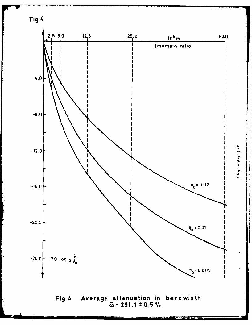
Fig4
2.5 5,0 12.5 25.0 5m 50.0
II(m mass ratio)II
III
-4.0 I
-8.0
IIII
_IIIIIIII
-12.0 -
II oII I
-20.0 I
I
-24.0 - 20 ogio V
I I
I = 0 I0 0 5
I -
0n
Fig I. Average attenuation in bandwidth

00U) - D
N+
- N 13
0
EIn0
40
C14u
CoCC4C
I.-I
Co - CU) A
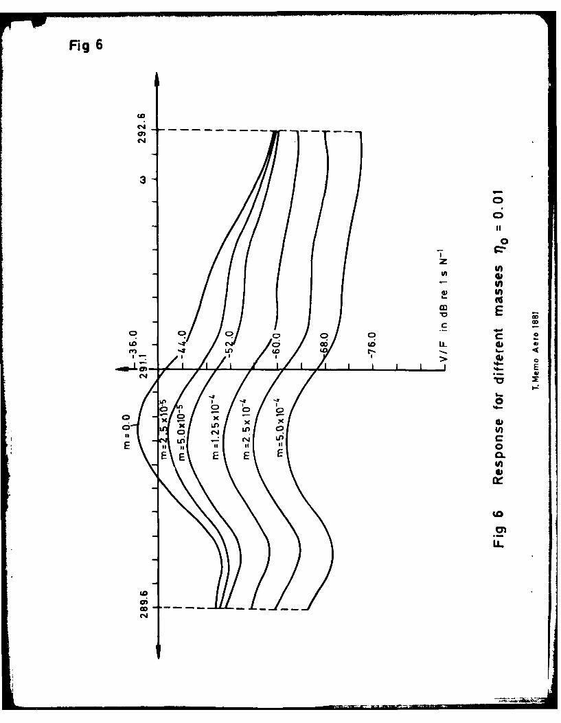
Fig 6
3-
0f
0
U)
EC) C)
'4- 00
16-
C)C
01 C-4Lo.
C4
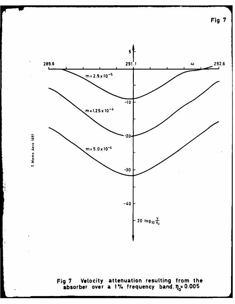
Fig 7
59289.6 291.1 C)292.6
M z2.5x 1-
-10
0E
-3.0
-20 logl iV
Fig 7 Velocity attenuation resulting from theabsorber over a I % frequency band. n =O.005
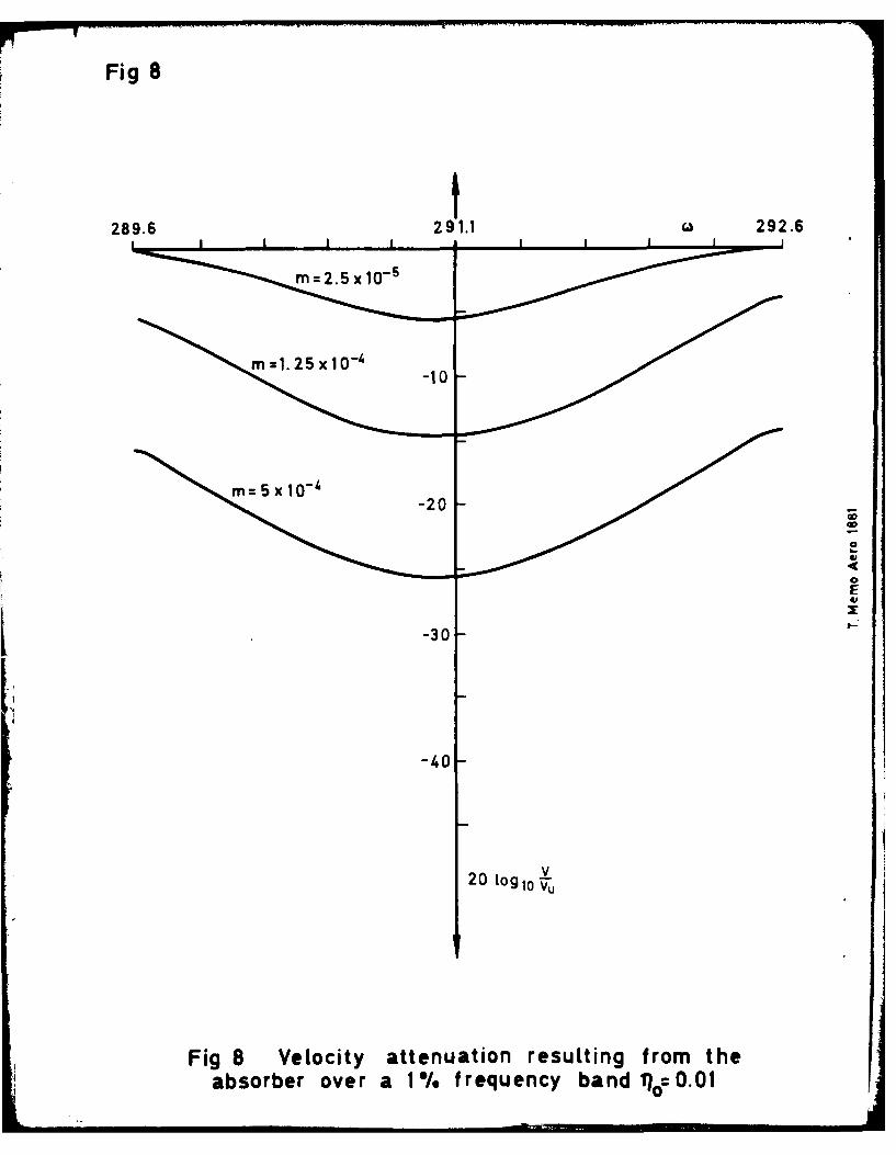
Fig 8
296291.1 292.6
-10
E
-30
-3.0
20 log 1o Vu
Fig 8 Velocity attenuation resulting from theabsorber over a 1% frequency band %o0.01

Fig 9
289.6 29.1f29.
291.125292.6
01
03
-40
20rgl
VU
Fig 9 Velocity attenuation resulting from theabsorber over a 1%. frequency band 1?o:O.O2

Fig 10
C.D
Co 4I
xx x IE
-n C C 0
E. EE
t- E
V)
Lnn
C C
I L,

Fig 11
05
-20
0V
20t lo u
Fig 11 Velocity attenuation resulting from theabsorber over a 2%. frequency band 11o=O.OO5

Fig 12
5963.2 63.8 64..4
m 2.5 x 10-'
M 5.0 X 10⁻⁴
-20
-30
V20 Logio-v,
Fig 12 Velocity attenuation resulting from theabsorber over a 2%. frequency band 0.01

Fig 13
05
63.2 63.8 64 .4
=2.5 x10 "4
=I.5 x 10- 4
-20
-J
I.- -30
20 Log 10 V
Fig 13 Velocity attenuation resulting from theabsorber over a 2% frequency band qo= 0.02

REPORT DOCUMENTATION PAGEOverall security classification of this page
UNLIMITED
As far as possible this page should contain only unclassified information. If it is necessary to enter classified information, the boxabove must be marked to indicate the classification, e.g. Restricted, Confidential or Secret.
1. DRIC Reference 2. Originator's Reference 3. Agency 4. Report Security Classification/Marking(to be added by DRIC) ReferenceRAE TM Aero 1881 N/A UNLIMITED
5. DRIC Code for Originator 6. Originator (Corporate Author) Name and Location
767300CW Royal Aircraft Establishment, Farnborough, Hants, UK
Sa. Sponsoring Agency's Code 6a. Sponsoring Agency (Contract Authority) Name and Location
N/A N/A
7. Title Reduction of structural vibration by a dynamic absorber
7a. (For Translations) Title in Foreign Language
7b. (For Conference Papers) Title, Place and Date of Conference
8. Author 1. Surname, Initials 9a. Author 2 9b. Authors 3,4 .... 10. Date Pages Refs.
Williams, JM. December 26 i 2
I I. Contract Number 12. Period 13. Project 14. Other Reference Nos.
N/A N/A15. Distribution statement
(a) Controlled by - Unlimited
(b) Special limitations (if any) -
16. Descriptors (Keywords) (Descriptors marked * are selected from TEST)
Dynamic. Absorber.
17. Abstract
This Memorandum describes the transmission of vibration in dynamical systemsand a particular example is studied in detail. This consists of two freely supportedelastic plates, connected by a rigid link. It is shown that the addition of a dyna-mic absorber to such a system can significantly attenuate the transmitted velocitiesover a chosen narrow band of frequency.
VA
MA Form A 143

Ns
Related Documents