UNCLASSIFIED ADl13545 CLASSIFICATION CHANGES TO: FROM: TO: unclassified confidential Approved for public release, distribution unlimited FROM: Controlling Office: Naval Research Lab., Washington, DC. NRL ltr dtd 4 Aug 1998; Commanding Officer, NRL THIS PAGE IS UNCLASSIFIED

Welcome message from author
This document is posted to help you gain knowledge. Please leave a comment to let me know what you think about it! Share it to your friends and learn new things together.
Transcript
UNCLASSIFIED
ADl13545
CLASSIFICATION CHANGES
TO:
FROM:
TO:
unclassified
confidential
Approved for public release, distributionunlimited
FROM:Controlling Office: Naval Research Lab.,Washington, DC.
NRL ltr dtd 4 Aug 1998; CommandingOfficer, NRL
THIS PAGE IS UNCLASSIFIED

CONFIDENTIAL
NAVY DEPARTMENT - OFFICE OF NAVAL RESEARCH
NAVAL RESEARCH LABORATORY WASHINGTON 20, D. C
CATALOG OF ANTIJAMMING
METHODS AND DEVICES
Prepared By
THE WORKING COMMITTEE ON ANTI-JAMMING OF THE
JOINT COUNTERMEASURES COMMITTEE
V»rfrrfi :NTWL
M; laiiaMi COPY NO. 112
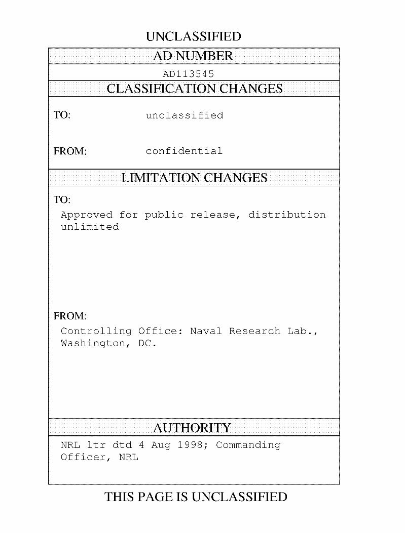
IAVX BEPARTMEHT - OFFICE OF HAVAL RESEARCH
RIVAL RESEARCH LABCRATGBX WASHINGTON, D.C.
MOBILE COffTROL DIVISION]
CATALOGUE OF ANTI-JAKMIHQ METH0D8 AND DEVICES
Praparad by
Tha Working Coamlttaa on Anti-Jumlng of tho Joint Countarnaaauraa Ooaalttaa
Saptaabar, 1945
' Publlahad by Arrangaaant With Tha Joint Countaraaaanraa Coanlttaa
Auguat, 1946
Approvad byt
Dr. ft.N. Faga Coaawdoro H,A»
, Uaalla Control DlTlalon Dlraetor, tetal
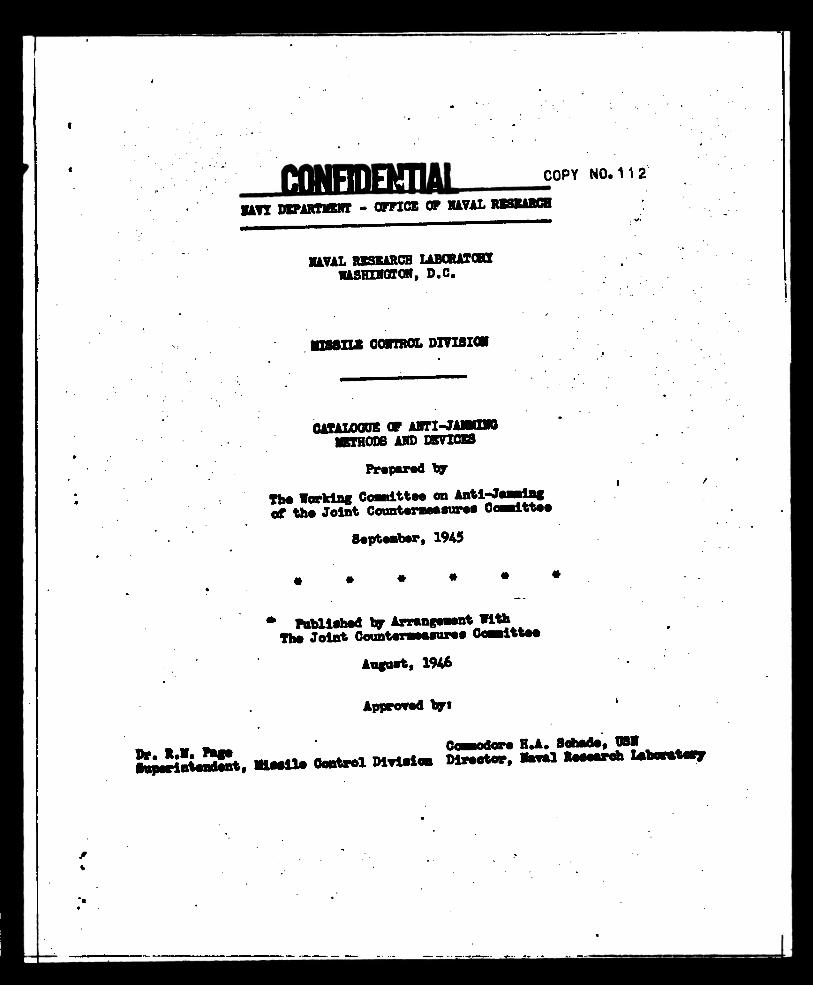
To peat an urgent war-need, the "Catalog of Antl-Janalng Methods and Devices" was originated and prepared on Seoteaber, 1945 by Tha Working Coawdttee on Antl-Jaaning of tha Joint Counteraeasures Coaaittaa. At tha eonolualon of World War II, tha Working Coaaittaa baoaaa inactive shortly aftar submission of thia "Catalog" to tha Joint Countaraaaanraa Coaaittaa. Tha A-J Coaaittaa in raeoaaandationa contained in tha alnutaa of tha final aaating (JX/CM 55/9 datad 15 Saptaabar 1945) pointed out that "antl-J«aaing for aaeh type of radio wave device be aada tha responsibility of tha ap- propiata ooaalttaa of tha Joint Coaaunleatlona Board".
Ruaaroua requests froa service project engineers and contractors for radars directed to tha Naval Research Laboratory have indicated tha need for publication and dissemination of tha "Catalog". Therefore, la re- sponse to a latter froa NRL (867-7(1131), 1100-266/46, datad 22 July 1946), publication of the Catalog by the Naval Research Laboratory aaa concurred in by tha Joint Counter-measures Coaaittaa (Joint Chiefs of Staff, JZ/CM latter to NRL, datad 21 August 1946).
Tha present "Catalog" (JA/R 81) has bean reviewed and plaoed in final fora for publication by the Naval Research Laboratory. Requests for eopioa say be directed tot
Tha Director Naval Research Laboratory Washington 20, D.C.
R.L.
10

flfflKIBEHAli
FOREWORD
The military requirements of any new radar system must now take into account all types of enemy countermeasures which might be used against it. Jamming must be exneoted in any future operations against an enemy. In World War II, protection against enemy jamming often was sacrificed for other military requirements and in order to speed up developments and get new and improved types of radars into the field. This was justified in that the enemy countermeasures efforts did not seriously affect the operating efficiency of most of our radar equipments. This will certainly not be true in the future. Anti-jamming must take its place with range, target discrimination, aceuracy, etc., as a definite Military requirement.
Innumerable trick circuits and "black boxes" were developed which improved the performance of certain radars against several various types of enemy countermeasures. The information on these devices, for the most part, was highly classified and did not receive sufficiently wide dissemination among those responsible for radar research, develop- raent and production. In order to solve this problem, this catalogue was prepared. The purpose of this catalogue was to assemble in one document a brief outline of all proven anti-jamming methods. It *as intended that this catalogue would serve as a handy reference for all who have need of anti-jamming information. It was not intended to provide complete information on any anti-jamming features, but merely to serve as an index. References are given on each item, which should be consulted before that item is included in any specifications for a new radar equipment.
One of the principal difficulties encountered in the inclusion of anti-Jammin«T in a new radar 1P the setting up of test methods and quantitative specifications for the performance of these devices. No attempt has been made in this catalogue to do this because of the many different types and applications of radars. The performance of the anti-jamming features muet necessarily depend on the characteristics of the radar in which they are included. However, test methods and performance data on the majority of anti-jamming devices included in this catalogue will be found in r.iany of the references riven. Also, it is expected that adequate specifications on anti-jamming performance can be evolved from vulnerability tests of the developmental models of new radar equipments.
It is intended that this catalogue will be kept up to date, and as new anti-lamming circuits are developed, brief descriptions and references on them will be made available to holders of this catalogue.
The Working Commute* on Anti-Jamming of th* Joint Countermeaeurea Committee
September, 1945
-1-
1.
2.
3.
I.
5.
6.
7.
8.
9.
10.
11.
12.
13.
U.
15.
16.
17.
IS.
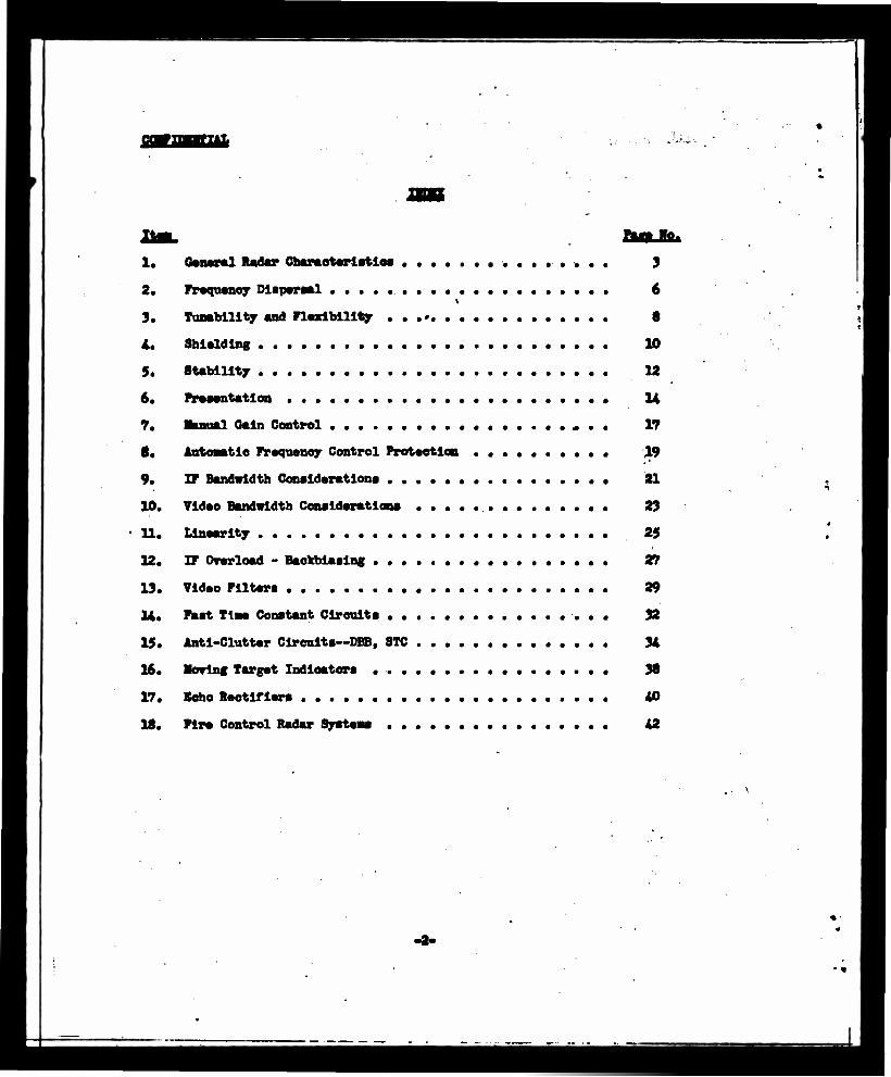
General Radar Charaotariatloe
Frequency Dispersal
Tunability and Flexibility .......
Shielding
Stability
Presentation ....
Manual Gain Control
Automatic Frequency Control Protaotlon
IF Bandwidth Conaldarationa
Video Bandwidth Conaldarationa . . . .
Llnaarlty
IF Overload - Baokbiaalng
Video Flltara
Faat Tine Constant Clreults
Anti-Clutter Cireults—DBB, STC . . • .
Mowing Target Indicators .......
Beho Raotlflers ......
Fire Control Radar Systena ......
3
6
S
10
12
U
17
19
21
23
25
27
29
32
U
38
40
42
a—] rtmdMr ShiEMtteUttei
A. ttrlaf BMflttettaa
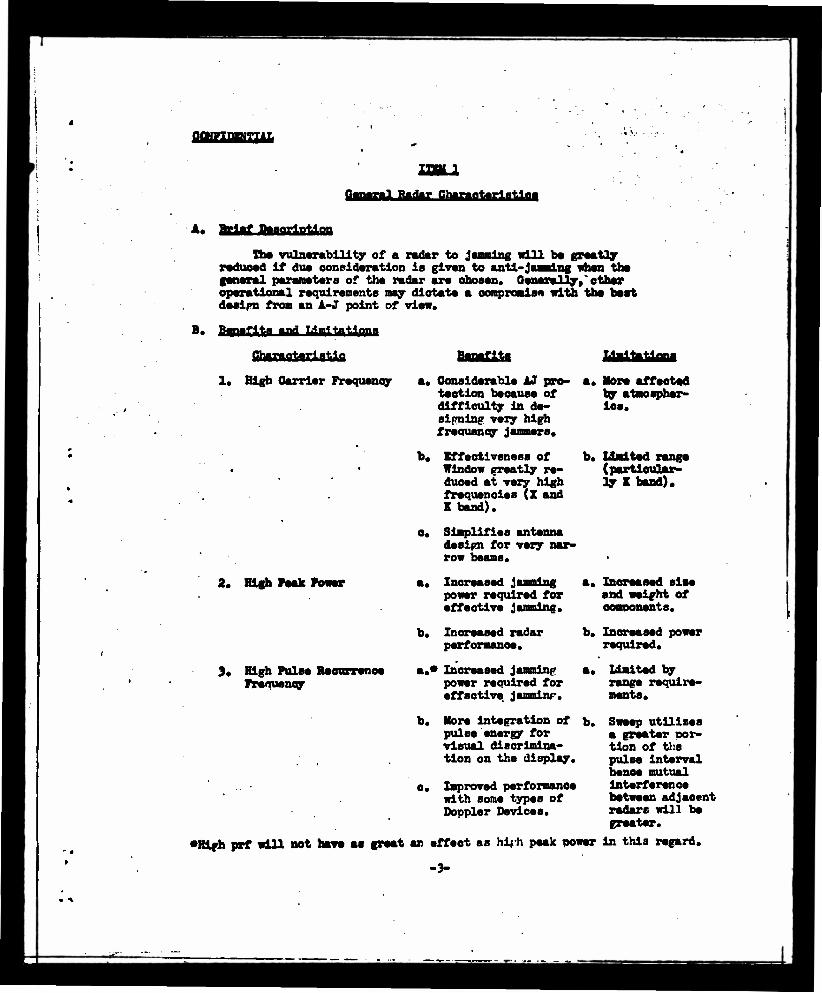
The vulnerability of a radar to Jamming will be greatly radueed if dua consideration is given to anti-jamming when the general parameters of the radar are chosen. Generally, other operational requirements may diotate a compromise with the barb desipn from an A-J point of view.
B. BfMflta and Liart tatltms
QhaxaaJarAaUa
1. High Carrier Frequency a. Considerable AJ pro- tection because of difficulty In de- sifmlngr very high frequency jammers,
b. Effectiveness of b. Window greatly re- duced at very high frequencies (Z and K band).
o. Simplifies antenna desipn for very nar- row beams.
More affeoted by atmospher- ics.
Halted range (particular- ly K band).
2. Ugh Yeah Power
). High Pulse Recurrence Frequency
a* Increased jamming power required for effective jamming.
a. Increased sise and weight of ooBDonents.
b. Increased radar performance.
a.* Increased jamming power required for effective jamminp.
b. More integration of pulse energy for visual discrimina- tion on the display.
e. Improved performance with some types of Doppler Devices.
b. Increased power required.
a. limited by range require- ments,
b. Sweep utilizes a greater por- tion of the pulse interval hence mutual interference between adjacent radars will be greater.
•Hifh prf will not have as great an effeot as hiph peak power in this regard.
-3-

mntKxm
, Characteristic
L. Short pulce Jenpth
5. Hii-h Antenna Gain
•
Benefits
i
a. Increased definition which is particularly effective apainet Window and other types of clutter.
a* Increases the beam power hence in- creases the power required of a jnm- mer for effective j&mminr.
a. Wide band width required in re- ceiver increases design problems and makes appli- cation of certain backbiasinff AJ circuits consider- , ably more difficult.
a. Increases dif- ficulty of target acquisition.
Requires larger antennas.
6. Mean.- for Chanrinr Antenna Polarisation
&. llore complex f.aternii de.-ipn.
b. PrcLuer considerable protection aratnrt Jammlnp when r. Jammlnp transmitter is located off anple from the tar tret.
c. Increarer the rerol- ii t ion o:' the radar w'rich rec'.cec -the effectiveness cf Window.
c. Increase- rnrcr • performance.
a. C< n fTeatly re- duce nlarie ellip- ticr.lly or circul- ar! v nolnrized .lamr.inr.
b. Can ireatly reduce the effectiveses.. of certain types of Window.
C. BMWMetetiflMH
1. The .iphect frequency compatible wi-,h rerforiiauce reouirementr. should always be used.
2. The hirhest peak power compali le wit" rrace, v.»iri.t, ant supply powftr rho-ilc be urea.
3. A hirh r>ul:e recurrence frenuency should t>e -.ire:'.. However, in- creased reak poiser will -e more valuable thuD ' ricreh.ee: i-rf henoa, if the duty cycle if fixec, ire prf ajfertuV "t-f levered wi-i^- a ccrre- sponclir.r increare in nenk rower.
-A-

MMEifiBam
4. A very short pulse length (l/4/faeo or less) is very valuable against Window, and should be used whenever possible. However, wide IF and video bandwidths are. then required which make the inclusion of several other AJ circuits extremely difficult. It is recommended that two pulse lengths be available, the first very short, for use apainst window, and the second considerably longer (l-2/^secs) which will require considerably narrower band receiver components and which" with the proper AJ circuits should be used against transmission jamming. A single switch which will choose either pulse length and its corresponding band width will bis very valuable.
5. The highest antenna gain, compatible with the operational require- ments, and the size and weight of the antenna which can be tolerated, should be used.
6. Means should be provided for changing the polarization- of the antenna in operation. If this is not practicable, provision shall be made to permit change of polarization as a maintenance adjustment.
D. BjfJMMBSsa
1.' Radiation laboratory Report No. 72. "The Power Necessary to Jam a Microwave Radar,11 J. L. Lawson, dated 24 March 1943.
2. Radio Rebearch laboratory Report No. HRL-44, "Notes on Power Required in Noise Jamming."
3. NRL Confidential Report No. RA-3A 208A "Minimum Detectable Radar Signal and its Dependence upon Parameters of Radar Systems", A. V. haeff.
4. Aperiodic Pulse Timinp Systems Pat. Apl. Serial No. 462,525; October 19, 19*2 S. C. Kight, Govt. Pat. Exch. Sheet A-1208.
5. Radiation Laboratory Report 54-28, June 3, 1943 "Slide Rule for Microwave Antennas".
6. Anti-Jamming Committee, Div. 15, N.D.R.C. Minutes of Meeting No. 9, Nov. 6, 1943.
7. Patent Application No. 563,559, filed 15 Nov. 1944, L. A. Meecham, B.T.L.; Govt. Pat, Exch., N-7S8.
8. RRL Report "An AJ Measure for Use Apainst Circularly Pol- arized Jamming", Division 15, No. 411-207, 20 June 1945*
-5-
OCIJMBITIAL
txgamw DiaB>rB*i
A. Brlnf Degorlntlon
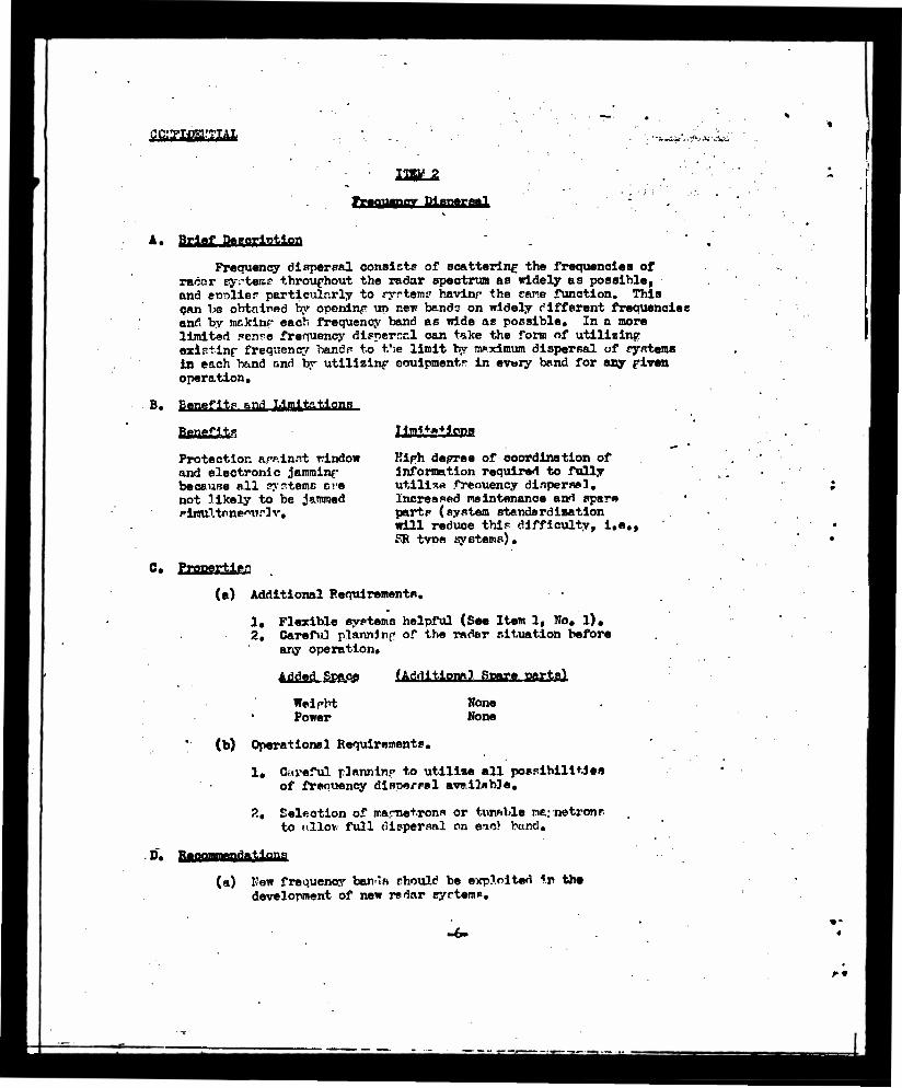
Frequency dispersal consists of scattering the frequencies of rador syrteir.e throughout the radar spectrum as widely as possible, and ernliep particularly to ryrteme havinr the cane function. This CAn lie obtained by openinp up new bands on widely different frequencies and by mrkinf each frequency band as wide ae possible. In a more limited scare frequency disperncl can teke the form of utilizing exist-inf frequency bandp to t.'ie limit by maximum dispersal of systems in each band ond V utilizing cauipmentr in every band for any riven operation.
B. Benefit.* and Limitations,
Baagfite Protection app-innt window and electronic jamminf becsuse all n>-sterns eve not likely to be jammed plimiltone^tirtv.
Kiph decree of coordination of information required to fully utilise freauency dispersal. Increased maintenance and spare part? (system standardization will reduce this difficulty, i.e., PR tvpe systems).
0. PEppertftpp
(a) Additional Requirements,
1. Flexible systems helpful (Sea Item 1, No. 1), 2. Careful plannJnp of the radar situation before
any operation.
Added. Space (Afrttttaml Pjflfg, Mffi&feO
Weirht Power
(b) Operational Requirements.
None None
D~.
ls Careful planning to utilize all possibilities of frequency dispersal available.
2, Selection of ir.arnetrons or tunnbla ne.; netronr. to nllo* full dispersal on eio> band.
(a) New frequency ban-In should be exploited in the development of new radar syrtems.
-6-
r*

fifiSEXBSSIAJt
(b) Old frequency bands should be exploited to the maxima by careful radar planning.
(o) Standardisation progress should be utilised to simplify operation and maintenance of radar systems,
(d) The practice of setting up all equipment of a given type on one frequency should be avoided*
It Tt*f**'nil">M
(a) A. J. Practices Handbook - Vapor A-l.
fifiHEiJB&JAi,
ITEM %
gmhaua Mri EOflgttajJJg fn flnfar fhrntaM
A. Brief Description of Systems
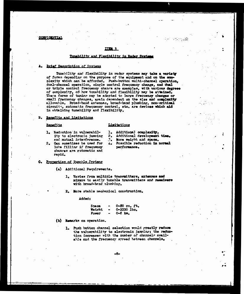
Tunability and flexibility in radar systems nay take a variety of forms depending on the purpose of the equipment and on the com- plexity which can be afforded. Push-button multi-channel operation, dual-channel operation, sinrle control frequency change, and dual or triple control frequency ehanre are examples, with various degrees of complexity, of' how tunability and flexibility may be attained. There forms of tuning may be adapted to larpe frequency changes or email frequency changes, apain dependent on the size and complexity allowable. Broad-band antennas, broad-band plumbinp, non-critical circuit':, automatic frequency control, etc. are devices which aid in obtaining tunability and flexibility.
B. Benefits and Limitations
Benefits
1. Reduction in vulnerabil- ity to electronic .lamndng and mutual Interference.
?.. Can sometimes be used for 4. lobe fillinp if frequency changes are automatic and rapid.
C. ProTiertiea of Tunable FyeHjerif
(a) Additional Requirements.
MgLtaJjIanj!
1, Additional complexity. Additional development time* More weifht and space. Possible reduction la normal performance.
1. Varies from multiple transmitters, antennae and mixers to easily tunable transmitters and receivers with broad-tend Dlumbinp.
2. More stable mechanical construction.
Addedi
Snace - 0-80 cu, ft. Weipht - 0-2000 lbs. Power - 0-8 lew.
(b) Remarks on operation.
1. Push button channel selection would freatly reduce the vulnerability to electronic jamminc; the reduc- tion increases with the number of channel." avail- able and the frequency spread between channels.
-8-
r*

2. Single-control frequency change em • wide frequency bud would make a system practically invulnerable to electronic jamming; over a aamll frequency raaga It would atill greatly ameliorate diffieultlaa with jamming and would allow optimum operation of receiv- er a-J elroulta.
3. Aa tha number of control! ara Ineraaaad tha flexibi- lity decreases.
A* Bvan aa easily tunabla loeal oaoillator oan greatly aid in tha oporatlou through jamming.
0.
•vary radar system should ba daalgnad with •Mrl— flexibility tunabllity (ualag a wlniauw of controls) oeBalataat with tha alma, walght, purpose and operating limitations for that particular equip- ment, la all oaaaa tha stats of tha art oa tunabla and broad-band components should ba exploited.
I, References
(a) A. J. Practices Panel Handbook - Paper A-l, A-2
(b) Development work at R.L. on microwave equipments. Development work at MRL on aster wave equipment. Development work at FTftH on water wave equipment. Development work at RCA on meter wave equipment.
»-•< •. •'.: *• vr
A. ariaf BMaaatla rf taattoM of tblaUU* Kleetrie and aagaetie shielding Is laportent la radar equlpaent
la order to prevent all unwanted olootroaagnetio flalda froa affeet- lag the receiving aretea. It la to ba understood that filtariag la a fora of shielding.
Shielding la particularly laportaat to ollataata or raduoai
1. Jaaalng at tha lntaraadlata frequency.
2, "Breakthrough" of radiation froa nearby aonreaa, aoeh aa radara and othor alaotrloal devices.
Shielding la alao an laportaat factor In anaurlng stability of tha radar aat (aaa Itaa 5).
lotai Tha site of a radar aat nay ba ao ehoaan aa to take ad- vantage of tha terrain to ahlald tha radar froa aa undesirable inter-
' faranea.
B. Bjaaat! mg iipitationg LJajjajflaaj
1.
0.
1. Proteotloa agalaat pick-up of unwanted algnala.
Additional raqulreaantat
1. Dealgn of tha r-f aaetloa for nadoalred frequencies.
2. Minimal 1-f and video oabllng.
3. Liberal filtering of leada.
nonerks oa operations
•one.
poaaible attaaoatloa of
D.
Although aeraal good dealgn ahoold provide ahlelding of auf- flolently high quality, oareful thought ahould ha given to tha natter of 1-f pick-up, eapeeially in aata whleh are knoaa to ba aubjaot to
•10-

difficult***. T««ts ahonld inelndo In an aoproprlatoly diapoaad field par uttr at tha lntoradlata
laful operation with- eff approxlaataly 1 volt
0,
1. RL Report Wo. 471, "Shlaldinf of Mi Interferenoo at Intir—dlate Preqoancle*'
BlMlWI AfKlUt Cork.
•11-

0.
Stability
A. Brief PeaarlBtlaii of Stabllltw Reoulrenanta
Circuit stability Is Important in both radar transmitter and receiver, lack of traaaalttar stability way raault In alaaatehlng of tho antenna, aaka re-tuning naeaaaarjr daring a arltleal period, or oanae falaa Dopplar offaeta In tboaa equipments utilising MTI or alailar devices.
It la necessary that tha antIra receiver, and particularly tha 1-f amplifier be atabla. A atabla local oacillator and a reasonably atable power supply are alao necessary. The atablllty of tha 1-f aapllfler la particularly Important because jamming nay ineraaaa tha Instability to tha point of oscillation. Baekblaa olreulta (aaa Itaa 12) should not decrease 1-f aapllfler circuit atablllty. Both erratic and periodic local oaoillator frequency variations should be kept snail In eonparlson to tha IF band width.
B. BjBtgai MJ LliiaaaM Benefits
1. Tranaalttar
a. Maintenance of tuning and initial conditions.
b. Avoidance of falaa Dopplar effects.
2. Receiver
a. Improved operation in Jamming.
b. Receiver gain lass dependent on Jaaalng signal.
0. Constant bandwidth with gain.
3. Local Oscillator
•• Retuning seldon required.
b. Necessary for use with optima bandwidth olreulta.
e. An eztreaely stable local oaoil- lator nust be available for use with MTI.
ygia&ionj
a.
Additional Requlreasntsi
-12-
D.
1. Batter shielding, batter voltage regulation, m filtering. It any ba necessary *• nae lever gala extra or larger ooaponenta any ba Beaded to gat ling. All those refiasaanta will depend oa the stability that oaa ba tolerated.
deeoup- ef la-
It la essential that the Initial design of a stable operation. It should ba pointed out that looal osoiUator Instability is net as serious when • well proteeted AFC elroalt la eaplojed. (See ltea 6) Teats of reeelvcr stability should include tests with Jaaalag signals present. Changes la temperature aad hnaldlty should have a very Halted offeet oa circuit stability.
I.
1. U Fraetloes Panel Report! B-7 "Stability Margin" by I. H. Page.
-13-

'-vivw'Ji-V.'.Vi ,rt .
A* Brl*f Description of Circuits and Function*
Th* aoat that on* oan aecoaplish in the way of U once the Jaa- •lag has boon neraltted to reach the indloator Is to display th* in- formation In such a way as to aaxiaiie the signal visibility in interference. Various display eyateaa aeeantnata difforant character- istics of the signal. Tha principal elassas used aret
1. Deflection-nodulated indication (such as "A", "J", "R", ete.
2. Intenalty-nodulated display ("PPI", "B", ote.).
3. Aural Indication. In this typo of indication a rang* gat* is •ad* to aneoapass th* echo, and th* audio Modulation d*rlT*d froa th* signal is amde perceptible through ear-phonee or othar suitabla Indicating devices. It is usaful in obtaining propel- l*r aodulatlon or Dopplar Indications.
A* M*t*r Displays. In this typ* of display a siapl* indicator, such as a mater, light, or ball, is actuated by th* signal.
These displays can be sat uo and used in a variety of waysi
(a) Expanded presentation. Th* rang* and/or asinuth is ex- panded to paralt easy signal visibility.
(b) Photographic projection. Th* display is photographed, rapidly develooed, and projected on a screen.
(a) Flicker technique. Successive photographs or skiatron laag*a are projected for eomparlson, so that novensent of targets oan be seen.
(d) Multicolor screens. Screens whose eaitted color is de- pendent upon the duration of excitation are now being developed.
B. Benefits and Limitations
LUilHtlmi 1. Deflection-nodulated lnd'.oatlon
a. Wide effective dynaaio range of presentation) hence less suscep- tible to Jaaalng.
b. Can act as convenient test seop*.
Vet well-adapted to aoanning search systeas.
-U-
a. Halted dynamic
2. Intensity-modulated Indication
a. Well-adapted to scanning
3. Aural Indication
a. Can bo useful In detecting moving targets In clutter, because of Doppler sffoots and propeller •adulation.
4. Motor display
a. Simplest typo of prooantation.
5. Expanded swoop
a. Discrimination, whioh Is especial- ly holpfal in clutter, Window, and tho Ilka.
6. Photographic projection
a. Increased time in whioh obsorvar oan a. Slight delay In scrutinise and judge tho display. processing and pro-
Requires a "gate" oa tho target.
a. Limited applioatlon.
b. Bully Ji
a. Rostriotod roll
b. Permanent rooord.
e. Advantageous for largo nunbor of observers.
7. Flicker Technique
a. Discrimination between Boring tar- gets and clutter.
b. Otherwise, aa for photographlo projections.
8. Multicolor screens
These are in experimental stage, and, at tton cannot bo amdo.
Jootion.
a. Requires double display, with In-
ooaplexity.
e.
, an evalue-
1. All radar aets should bo provided' with a dof lection-nodulated oa- ollloseope, If possible.
2* Radar sets should be provided with expanded presentation where possible.
9, Tho use of other techniques should depend on tho character and use of particular radars.
-15-
0.
1. Screen propartlea • W.B. Bottlnghaa, RL Report Be. Sea. 6-ifl, 1/22/42.
2. Prlnolpal dorolopnont en nultioolor UNMI at Doaont Labora- tories and G. B. Reeearoh Laboratory.
3. Photographic Integration and Spread of Baaa Liaei RCA Taehnloal Report PTR-7C, by T. T. Baton and Irving Wolff.
A. Flickeri Development work done In England by TBS and ASIDE.
BL Report Bo. S-10. BRL Report Bo. R-2561 by A. B. Hastings.
5* Aural indications (a) RL Report Bo. S-10.
Pirrnl flaja Bated A. ftrltf BuglB&lgB
The manual gain control la an arrangement for annually adjusting the 1-f gain during operation of the radar. In the preaenoe of Jam- ming, overload oan be largely prevented by manipulation of a properly dealgnad gain control and the susceptibility to jamming greatly redneed.
Thla control can be uaed during normal operation to aet the gala of the receiver to give optimum visibility of the target pipe on the radar indicators. For strong signals it Bay be need to prevent over* load and to increase definition. There are several types of gain con- trol with different overload characteristics and dynulo range. It la essential to consult referenoe (a) for details.
B. Benefits and Limitation*
Ifj
1. Alleviation of 1-f and video over- load.
2* Inoroesed definition and discrimi- nation for large signals at expense of weak signal visibility.
MaUatilflM 1. Extent of value is
Halted by the speed with which the op- erator oan properly
. adjust device.
2. In scanning radars, if overload Is pre- vented in Jammed sectors by gala re- duction, in general the visibility of weak algnals la un- jaaaed sectors is reduced.
0. WWie flmll SflBfaBl lm<
Additional Requirements*
3 An operator's control potentiometer. Extra cabling, If receiver control is remote.
! Decoupling networks for individual controlled Biasing voltage with small power drain.
stages.
t Space Extra weight varying with installation but Weight amounting to less than a pound in most eases. Power
2. Remarks on Operationi
(a) Scanning limitation removed by using autoaatle baok-blas
-17-
D.
(••• Xtan 12) tat tlwa* oiroutti etun differentiation of tha elgnele.
(b) If the clutter pattern Is approxiaately the MM at all aal- •utha, STC (see Itaa 15) la prafarrad ovar tha aaaoal gala trol ataaa It preeervee aaalana aignal Tiaibility at all rangea.
(a) In oontraat to thaaa alternate seheaaa, tha annual oontrol, la general, requires tat llttla added elroult eonplexity.
A annual 1-f gain control ahould ba provided baoauaa of ita AJ ad- vantagea, area If net required far ethar raaaona. It la eeeentlal that tha 1-f gala oontrol hare adaqoata rang* aad eatlefaetory overload aharaatartatlaa aa dlaeuaeod la Reference (a) below.
I.
(a) AJ Praetloaa Panel Report! Paper B-4, "Gain Control Applioationa", by R. 8. O'Brien.
•18-

Ajftflsjfljj Frequency Control Protection
A. Bwlaf BtiflElaUaa °f Scheme and Function
Protection of the AFC in desirable so that external signals oan- aot oontrol the frequency of the local oscillator. If an external signal should detune the local oscillator, there would be a serious iapaiment of radar visibility, and an increased J/S ratio.
In the simplest forn of AFC, the frequency difference between the local oscillator and the transmitted signal is kept constant at the intermediate frequency. This is done by means of a frequency dis- criminator, which furnishes correcting information either to the local oscillator or to the transmitter. Ordinarily no steps are taken to prevent external signals from taking control of the AFC circuit. Two schemes are customarily used to protect against this eventuality.
1. A gate is derived from the transmitted pulse, which sensitises the AFC channel only while the pulse la on. Leakage power through the TR box is used for AFC, Thus external signals are virtually eliminated by either the gate or the attenuation through the "fired* TR box.
2. A small amount of transmitted signal power is coupled out from the r-f transmission line to a separate AFC crystal miser. The at* tenuatlon through this coupling is usually more than 60 db. thus virtually eliminating external signal effects.
B. HMHfttl 1T11 Limitations of Sehame
BjMflit
1. Protection
C. Properties of Two Such Sohemsa
Bono
1. Additional Requirementst
A. Gated AFC.
1. Receiver modlfloa- tions and a gating pulse. This pulse may sometimes be tak- en from the modulator or synchroniser. If not, it must be gen- erated from a trigger.
Bi Bgmmat Mamml
1. Separate AFC Blxer and channel coupled to r-f lino through appropriate attenuator. 2. Additional LO power. 1. Decoupling betws the two mixer*.
Space Weight Power
20 cubic lnohes 1 lb.
20 cubic lnohes 1 lb. 10 w d-ci 2 w a-o
-19-
1—HM ou Oparatloai 1. Baaa mud
of adjait—nt. 2. Boaolal attention •oat be paid to tho elialnatlon of •pnrlooa
1. "Huh" from alttod algnal "apik*" r*qulr** apeolal oar* la tho design of tho gating pule* and la tho balance of tho discrimi- nator. 2. Special attention •not ho paid to tho elialnatlon of spurious •odea and harmonic*.
Doric* for protecting AFC ahould ha Included la all radar HU,
B.
Oatod AFCi DoTolop— at work largely don* at Boll Telephone Laboratory**. »•«, for example, BTL Report Bo. K5, "Antoaatle Toning Control Studies".
Double Crystal Mixeri Development oork largely done at Radiation Laboratory. See, for example, RL Report Bo. 687, "Some Automatic Frequency Con- trol Circuit*".
-20-
A. writf a—am MJ rrniTtinn The I-f bandwidth la the frequency interval over which an 1-f
ampllfler has an over-all gala net •or* than 3 db dowa Area
The amplitude of the 1-f bandwidth need la a receiver la a faster la determining the slgnal-to-nolss ratio, the degree of dis- tortion experienced by the poise daring reception, and the sus- ceptibility to ji
In ehooatng the 1-f bandwidth, the objective usually la to ob- tain as large a ratio of aignal-to-noise as possible even though the original shape of the pulse la aoaeshat distorted. This optimal bandwidth la obtained by using a 3 db bandwidth of about 1.3 tinea the reciprocal of the pulse width. In some eases, less distortion of the pulses can be tolerated and a wider 1-f bandwidth nust be used, nun skirt selectivity should be used consistent with the pulse dis- tortion which eaa be tolerated.
For nest ferns of .leaning an 1-f bandwidth chosen from the pre- ceding considerations will be satisfactory, although for particular types of jamming, a wider or narrower 1-f bandwidth nay give sone im- provenent of visibility.
B. BfMmi^fnd mutations of Bjthir Wjd,
1. Barrower Bandwidth then Optimal
(a) Increased "aettlng-on" difficulties for Jammer.
(b) hay be used as filter for "off-tune" ji
2. Wider Bandwidth than Optlana
Benefits
(s) Inproved visibility In "railings" and clutter.
(b) Inproved visibility in
Than Optima, I-f
Halfrtlgnt (a) Reduced signal vis-
ibility la reoelver noise.
(b) Bednosd visibility In "railings" sad clatter.
(c) Reduced visibility In nost forms of • tuned1
Limitations
(a) Reduced visibility in reoelver noise.
(b) Bases requirements
•21-

FR and clipped AM noise .leaning.
OB jl COntTOl.
frequency
0. toMCttM rf WidM> g Baa 9rtl 1. Additional Requlreaentss In general, wide 1-f bandwidth* require
•oar* tabs* and/or circuit eonplexity.
».
It la rooo—anrttd that aa 1-f bandwidth equal to ono-to-two tlaea tba roolprooal of tho radar pulse length bo need. Thlo consideration •ay bo Modified by toning otablllty and poise shaping requirements. Booauoo of lto value against clipped nolao Jaaalng, and clutter, a wido bandwidth should also oo eonoldorod. Rhereerer possible a dual band- width IF should bo nrovlded. Suggested bandwidth values ara 1/T and
I. Roforoncoa
1. A. V. Raoff, Revy Report Ro. 134,
2. A. R. Stone, RL Report Ro. 706.
3. RRL Report R-2508 "Son* Fuadaaontals of Anti-Jan Receiver Cir- cuits".
!
A.
IUM amiMtt aaanai
The video bandwidth is defined aa the frequency interval over whtoh a Tideo aapllfier haa an over-all gain net wore than 3 db doi froa the aaxiaua.
Other eonaiderationa than U requirements require a good lev* frequency reaoonae and henee the high-frequency 3 db point la es- aentlally equal to the video bandwidth. The proper shaping of the video response curve la dictated by the transient response required* Vote that in aoae eases very poor low-frequency response is intentio- nally introduced by an FTC (see Ztea 14) and here special considera- tions apply.
B. Ptrtn PjBfiagBttflM In the presence of Jawalng, a large video bandwidth la desirable.
Jaanlng which is not exactly in tune with the radar frequency beats with the pulse and auoh of the pulse energy is near a frequency equal to the difference between radar and Jawalng frequenoiea. If this dif- ference ia greater than the high-frequency cut-off of the video aapll- fier, a loss in pulse gain will result. This loss in signal response Is not aeeoapanled by a corresponding decrease In noise and bsnoe there Is a real loss in dlscernlbility.
0. Properties of Wide Tideo
1. Additional Requlri iUt (a) May requirei (1) added eonplewity la
video coupling circuits* (2) added tubesf depending on bandwidth desired.
Spaos •sight
(a) Depends on circuit requirements.
(b)' Added bandwidth can often be obtained slaply by appropriate pasting. The of peaking that can be effectively used ds panda upon the requirements, on transient response.
(e) Still wider bandwidths way require larger additional tubes and power.
2.
D.
Operation! Ion*
It is desirable froa the JJ point of view to wake the high-freqneaey 9 db point of tha video bandpass curve at least equal to the fall 1-f (3ab) bandwidth, (then a third detector la eaploysd It la advisable to wake tha
-23-
9<WIPSTOM
rldao bandwidth equal to twieo tha fall IF bandwidth up to tha third dataetor. (8M Iton 17.)
U Fraetleaa Panel Report i Paper B-3 "Video Bandwidth Coneldera- tlona" J. L. tawaon, 0. I. Hired, and A. L.
•aval Baaeareh Laboratory Rapertat (a) R-2392 "Sapert on In- •aatlgatlon of Anti-Jan ftooaivara for Seareh Radar"» (b) R-2506 " — *' " of Antl-Jaa Reoeirer Cireuita".
-24-

A. Brief Description
A linear receiving system la one ahoae output voltage la directly proportional to the Input voltage. linearity la set achieved if a square-lew aeeond detector la need, or If 1-f or video overload occurs. If a square-law detector la used, the Introdnetion of e-w Jamming Increase the nolae output enough to aaturate the video amplifier.
B. Ui uA liMiisiiau
1.
-3.
essentially constant nolae level aa a funetlon of o-w jamming in- put*
Mlnlelsatlon of angular errora In the presence of off •target Jamming.
Helps prevent Intensity nodulated Indicators frou saturating or bloeklng out in Jammed sectors.
e.
1. Unless very widths are uaed. a linear systea aay he leaa accurate than a nonlinear eyatea when tracking targets In the absence of Jamming. This limitation can ha avoided if a linear aya- ten la followed by a nonlinear video. An FTC (aee Xteu U) preceding the nonlinear video la neoeeeary to protect it froa the effects of c-w Janelng.
In relatively low frequency fire-control radars, which employ rather wide lobes, the use of a linear detector results In somewhat less di- rectional sensitivity than la obtained froa a square-law detector, if a linear video la uaed. The extra directional sensitivity aay be obtained by using a nonlinear video aapliflar fallowing the linear detector.
Use of video filtering to reduce the affect of Janelng modulation requires additional components. Filtering arrangements will vary froa a simple short time-constant coupling that la desirable for other reas to a selection of filters occupying considerable space and adding several pounds to the anight.
D.
A linear 1-f amplifier and aeeond detector are recommended for all radar equipments. A video filter, such aa the FTC (aee Item H), la necessary to remove the effects of Jamming aa much aa possible. This combination nay be followed by a linear video, or if desired for sensi- tivity in tracking, by a nonlinear video. (Refer to Item 18)
-25-
AJ Practices Panel Reportt Mo. B-5, "Linear Va. Square-Law Detection", by I. B. Page.
Additional Referencest (a) "A/7 Practice for Flre-Control Radar Systeas", HRL Technical Meaorandua, All-TM-87, 23 March 19U, hr H. 0. Anger.
(b) "A Study of the Vulnerability of the Radars Mark 3 and Mark A to Sneay Electronic Count eraeaaurss", HRL Report RA 3A 217A, 30 October 19U, by R. L. Flowers.
(e) "A Study of the Systea Vulnerability of the Radar Mark 12 to Electronic Jaaalng", HRL Report RA 3A 220A, 1 Deooaber 19U, by L. W. Sessions and A. J. Steooa.
(d) Ravel Research Laboratory Reportsi
R-2A56 "Standard Test Prooeduro for A-J Receivers"
R-2507 "Developaent of Mark 32 Anti-Jaa Receiver".
R-2508 "SOM Fundaaentals of Anti-Jejoilng Receiver Circuits".
.26.

I-f Prtrlffrt - BwlftlHlM A. Brltf Pttwlrtlw rf gghiPM infl BMMI
lest fores of jamming and clutter are strong enough to roduoo sig- nal visibility by overloading some portion of tfao receiver* Tldoo overload can bo alleviated by tfao FTC (aoo Ztoa U) and tho DBB (see Itoa 15). However, apoolal proeantioaa 0110014 bo taken to protest tho 1-f amplifier, Insofar aa possible without tho use of a aenm ' trol. Several methods, or combinations of nethods should bo
1.
2.
High level taboo la tfao last one or two 1-f stages1 e.g. 6aG7's la place of 6*C7's, etc.
Baekblaa. This lo a rapid aetlag degenerative olrenlt which re- duces tho gala of tho stages controlled aa tho output Increases. This reduces 1-f saturation and thua helps to prssorvs pulse gain. There are two general classes of baekblaa elroults, nooamplified aad aapliflad. Tho latter la frequently called aa Instantaneous auto- mat le gala control, IAGC. It generates a bias voltage by rectify- ing and amplifying the output voltage of the controlled stage or stages. The unampllflsd baekblaa clroult omits the amplifier stage.
B. Benefits and Llaltatlona of Various Schemes
1. High Level Taboo
a. Increased overload protection.
mmtiM
a. Effeotlve only against CW, both unmodulated and modulated at a lew frequency, and then only if followed by FTC.
b. Hot effective la reduc- ing video saturation la clutter.
2. I-f Baokbiaa
Proetectlon agaiaat i-f over- a. lead.
Under certain design conditions it way he need to protect against video saturation.
Effective 1-f baekblaa lo required b. for optimum performance of FTC aad DBB circuits.
-27-
It differentiates sig- nals, giving a false appearance of discrim- ination in solid land olutter (aoo note on FTC).
Amplified faaokblao quires a somewhat crit- ical design required to make a stable, effective circuit within JAM opee-

lfioation limits.
0.
1. Additional Requlresentsi
Space •eight
2. Remarks on Operations
0.
I»l High LT.I (b) ynwll- tg) Amplified
1. Largar Tnbaa 1. Additional 2. Additional 1-f 1-f stages.
1. A doablo triode par
stability. 2. Shortar tint loop pro- oonstants can taotad. bo uand than 2. Switch and with ampli- relay. flod back- 3. Additional
Slight Slight 6 watts d-e par tabs.
1. Satisfactory only against ow jaaning and only if follow- ed by FTC. 2. Rot neces- sary if ade- quate baekbiaa circuits are U»fid.
Mas
12 cubic inches 0.5 lb. 2 w d-ei 2 w a-e.
1-f stability.
(each loop) 12 cubic inehas 0.5 lb. 3 w d-e| 2 w a-e.
1. Satisfactory against both OW and clutter, if followed by FTC. 2. Amplified baekbiaa wore satisfactory, especially against cloud and sea clutter. 3. Only the aaplified baekbiaa is satisfactory for use with
X-f overload protection should be lnolndod in all ground and ship radars. It should also be included in such airborne search radars where added requirements are not a bar, particularly where risibility in sea and land clutter snst be maintained.
I. References
1. U Practices Panel Reportst Roa. B-2, B-9-*, B-9-b, B-9-e.
2. Principal development work on 1AQC at I. ..1 Research laboratory and at Radiation Laboratory. See, for exanple, RL Report Ro. S-52, "Antlelutter circuits for AIR".
3. RRL Report R-2392 "Report on Inraatigation of Anti-Jan Receivers for Search Radar".
A. RRL Report R-2456 "Standard Teat Procedure for U Receivers".
5. RRL Report R-2507 "Derelopnent of Hark 12 Anti-Jan Reoelver".
6. RRL Report R-2508 "Soae Pundairantals of Anti-Jan Raoeivar Ciroultm".
-as-
A. Brief PeaorlPtlco iid ymiatl—
of the frequency speetrua of Jamming out b» by tho wo of flltoro 1B tho video. Aloe, boat frequency between tho jamming and tho signal which carry radar lntelli- IB bo passed by flltoro which greatly suppress tho Jamming.
Tldeo flltoro aay have olthor high pass, baud past, or low paoo oharaetorlotleo.
B. BtR*flt| apd IdBltat^oBf
Hl1frl*1f«
1. High Paoo
Elimination of low and medium frequency aodolatloB of tho jaaBlag signal.
a.
d.
Tory boBoflolal against all types of off-frequency Jam- alag as It wi 11 paao tho hotorodyBo ooBpoaoato of tho jaaalng and aoho signals while rejecting tho fundamental Jaa- alng signal.
Improves resolution against elattor.
•ay ba of Tory alaplo design oad still bo effective.
b.
d.
2. Band Pass
Against jaaal&t modulated at both lav and high frequencies, can appreciable reduce Jaa-to- algnal ratio.
Can ba effective against narrow band barrage jaaalng.
a.
b.
•oho distortion which results la alight range Tor aeourate lag, rangi oatloB oust ba
Under certain con- ditions filter aay ring causing uul- tlplo indloatlons.
Loss la signal risi- bility when used against wary high frequency nodulated JaaalBg.
TaaortleB loss 1B video amplifier,
Loos of elgnal-to- nolse ratio If la- properly **ad.
Greatly loners rooc- lntien because cf poise distortion,
Bust be variable or several different pass bands treat be available to :* af- fective.
-29-

•x filter
3. hem Pui
a. Removes high frequency Jamming modulation component.
b. May be of very staple dealgn •till be effective.
a. Mora design.
d. Insertion loss In video amplifier.
a. Pulse distortion which slightly lovers resolution and range accuracy.
b. Insertion loss la video amplifier.
e. taamni at BJM 'Ufrn Mflrt BimiTTTiti 1.
2.
1.
2.
D.
1.
2.
3.
Additional components inelodlng switching system, video delay line (for range error eoapensation), possibly added video stages to eoapensate icr filter insertion loss.
added space, weight, and power requirements* These are usually •light but are dependent upon specific radar characteristics and the choice and nuaber of filters.
Iff 9B OpfflrtJQB
lomally the only control is a selector switch.
Performance is Improved through use of an echo rectifier (Itea 17) and a tunable transmitter system (Itea 3).
A high pass video filter, or FTC (Itea 14) should be Included la all radar equipments.
additional filtering should be considered if space, weight, and operational complexity permit.
In order that video filters be fully effective, it Is that they be incorporated in a radar system having a transmitter rapidly tunable over a narrow range, an overload protected IP ampli- fier, and an echo rectifier.
I. Roforonoaa
1. "AJ Practice for Fire-Control Radar Systems", RRL Technical randua, ai-TM-87, 23 aareb 19U, by R. 0. Anger.
2. NRL eonf ltr C-367-5/RCM(398tSWF) to BuCrd, Coda RsAf, Preblea 0-73T-C, "Type CA0S-50-ART IF to Video Converter, Operational a
-30-

BfwUm Toata", datad 26 Augoat 19U.
I. Ml R«port R-2507 'Davalopaaat of Mark 12 Antl-Jaa RaMlvvr".
4. OIL Report R-2506 "Soaa Fundaaaatala of Antl-Juaing Rooalvar Cirenlta".
-SI-

SaatiiBS BteaMBi
A. B»4af D—arlntlan of Bahomo end Function
The fast tine constant circuit, called RCV Is placed between tha sacond detector and first Tidao stage of a radar raoalTer. It con- sists of a differentiating circuit whose tlae constant is of tha order of Magnitude of the pulse length. This circuit Is effectively a high pass filter and thus aids In removing CW, or CW nodulated at low fre- quencies, froa tha succeeding video stages. It can also be used to advantage In ameliorating tha afreets of cloud and ssa return, hot op- erates bast for this service in conjunction with other devices. (See Iteas 13 and 15.)
B. B«i.flte and Limitation, of the Scheme
1. Effective reduction of video over- load in tha presence of CW, un- modulated or nodulated at a low frequency.
2. Improved operation in the presenoe of clutter and possibly Window protected by a good i-f baekbias.
1.
2.
Loss In signal visi- bility la Ian than 1 db even whan long
ips are used.
Because of the dif- ferentiation, long blocks of signals era broken up. However, the relative ampli- tudes of individual signals are not pre-
0. Fwaaartlea of the FTC and of nIVinilfr gtiltTI
latest 1. Since the DBB circuit is designed to perform some similar functions, saa Item 15 for a discussion of tha relative ad- vantages of tha two oircults.
2. Complicated differentiating circuits can be devised, but fef most purposes tha simple RC or IS oircults sufflos.
1. Additional Requirements! 1. A saitoh and relay.
Added Spaee Weight
5 cubic iiiehee 0.2 lb. 1 wd-e
2. Ooeratloni 1. The RC circuits are superior to the IS oir-
cults because of a shorter recovery tlae slble in a practical ease. However, IS air-
-32-
oults have the advantage pf lower Insertion lose or •harper low frequency cut-off.
D*
. The FTC should be Included In all radar seta,
I. References
1. AJ Praetleaa Panel Report: Be. B-l-b.
2. Prlnelpal development work done at If aval Research Laboratory and Radiation Laboratory. See, for exaaplev RL Report Mo. 3-52, "Antlelutter Clronlta for ACT".
3. HRL Report R-2392 "Report on Investigation of Anti-Jaw Receivers for Search Radar".
4. MRL Report R-2508 "Some Fundamentals of Anti-Jaw Receiver Circuits".
3. PAL Report R-2530 "AJ Video niters for the Radar Mark 12 Receiver".
-33-
15
JBMUl Antlelnttar Clroulta - 1. Detector Balanood Bine
A. Brlaf Daaortntlon of Clrenlt and Function
The dataotor balanced bias (DBB) la a circuit which la particu- larly useful In conjunction with IAOC (aaa Itan 12) for reducing tha loaa In radar visibility dua to oloud and aaa return, and which way ba uaaful In reducing tha effoctivenaas of Window janaing. It ope- rataa in tha following way. Tha aeeond dataotor In tha receiver la blatad by the DBB circuit in aueh a way that tha average detector oat* not reaalna approximately constant, regardlaaa of input algnal anpll- tudaa. Thla la aecoBpllahed by rectifying the output 1-f voltage, de- laying and amplifying it to eatabliah the blaa voltage. The response of the receiver to dlaorete algnala la essentially unchanged by the circuit action, while video saturation due to blooka of algnala la practically ellnlnated.
B. BenafIta and Limitations of the Schene
mawiM! 1. Inproved vialbllity In the preaence
of eland end aaa return and poa- albly Window.
1. Woeful only in aeta equipped with satlafaetory 1-f baek- biaa circuits.
2. Short shadows after large algnala. (Wot aa appreciable inereaae over the ahadowa with proper IAOC alone)
0. yf tti WB uA rf ti&asaafa 8rtn 1. Additional
Requlreaentai 1. Switch and relay. 2. Two dlodea and a
trlode. 3. Delay line. A. An effeetlve 1-f
baokblaa.
1. Switch and relay. 2. An effective 1-f
baokblaa.
Space Weight
30 cable Inches 1 lb. 6 * d-oj 3 w a-o.
5 •able 0.2 lb, 1 w d-o.
2. Operetloat 1. Better contrast on long eweepa than FTC.
2. Better parforaanoo in cloud return than HO.
-34-
3. DBB la net as effective as FTC la the presence of e-w .leaning, either unmodulated or modulated.
A. Critical adjustments of DBB are necessary to aeet JAN specifications.
5. In the presence of sea clutter, the iffeot- Ivenesa of either of these circuits la la- proved when preceded by STC (Itoa 15-2) la addition to th«> required i-f bacKbias.
6. The alaultaneoua use of FTC and DBB la not reeoaaended.
7. The DBB should not displace FTC froa a receiver.
D.
The DBB should be used la all radar sets where the clutter froa aaa and cloud return warrants the added complexity, but when included It should be used only la conjunction with IAGC. Ita operation in the presence of aaa return la lnproved, if STC (aaa Itea 15-2) la artliable. It la not a replaeeaant for FTC la all cases.
*>• Beforencoa
1.
2.
Principal development work done at Radiation Laboratory. Sea, exaaple, RL Report Ho. S-52, "Antlelutter Circuits for AEW.
for
Minutes Beating Ho. 13 Antl-Ji H.D.R.C. oa 5 June 1945.
•lag Conaittee of Division 15,
-35-

Wo. 15 (oont) Special Antlelutter Cireulte - 2. Scnaltlwlty Tine Control.
A. Brtrf lU.arlpttoB of Prica and Function
The aeneltlvity tlM control (STC) circuit la ueoful la reducing video eatoratlon duo to BOO, and poaalbly land, return. Considerably oahanood offeetiTonoaa la achieved by tho conbinod uae of STC with HOC (aoo Iten 12), followod by olthar FTC (aoo Iten H) or DBB (aoo Iten 15-1). Tho STC eporataa In tho following wayi a tlna-dependent voltage la generated whleh la need to control tho receiver gala. Tho attempt la aade to ohooao thla tine dopoadoneo In aaeh a way aa to Maintain tho rooolTor gain at lta aoat naoful value at all rangoa. Sono STC olroulta aro ooabinod with tho anaoal gain control In aaeh a way aa to lapoao tho doalrod STC wavofora on tho aannal gala voltage.
B. Baaaflta and Limitation* af tha Davloa
1. Uaeful la reducing aat atlon only by that ent of the clutter that la BO—en to all aalanthai thna not generally naoful la atorna and Window.
2. Critical adjuatawnta to achieve aatlafaetory re- aulta.
3. Mlaadjuatwenta any eauee lapalred rather than In- proved visibility.
1. Xaproved rlalblllty la aaa, and poaalbly land olutter, for aoat presentations.
0. Frgnavtlaa ef the STC
1. Addttloaal Baealreaaatai 1* Aa Initiating palae, aaeh aa a trigger.
2. Vaually at leaat oae additional tube. J. Switch *r relay to reader the STC lnopara-
tlwe aa dealred. 4. Panel oontrola for wavofora adjuatwant.
2.
Weight Fewer
Operationt
parhapa 50 cable perhapa 2 lba.
2 w d-0| 2
1. 2.
w a-e.
Applleablo to nearly all radar lets. Can be added aa aaall nodlfloatloa kit.
J>.
The STC ahould bo Included In all radar aeta where the poaelble la- in rlalblllty through aaa aad land clutter warraata the added
operational eeaplealty. Xt ahould be uaed principally la oonjunetloa with IAOC and either FTC or
-*-

E. Rrfwiaati
1. Prolopnont work dono largely at Saral Roaoareh Laboratory and at Radiation laboratory. 3M, for exaaple, RL book "Thoory and Fraetloo of Poland Clronita", by Donald 0. Flnkj Chap. VI. So* RL Report Ro. 3-92, "Antielnttor Circuits for JEW".
2. Rlnato Mooting Ro. 13 Anti-Janaing Connitton of DirUlon 15* E.D.R.C. on 5 Juno 1945.
•JT*

Mwlai Tarn* WHitm A. arlaf P—orlntlan of 8ahama and Function
Kfl, "moving target Indication" is an attachment to radar sets which differentiates between targata of high and low radial velocities, Is partleolar between aircraft and most forma of eluttaf auoh M land, sea, atom, and Window aehoaa. Ita operation dapanda on tha faot that •owing targata causa a ohango in tba phaaa of aoho pulses, and that tha rata of change of this phase la proportional to tha target Telocity, la alapleat fora the transmitted pulse Is aent out alwaya In fixed phaaa with tha carrier, and than split Into two video channels. Tha first delays the aoho a pulse repetition Interval by means of an acoustic delay Una. Tha delayed pulae Is Inverted In phaaa and added to tha following pulse In the other ohannel. Slow moving targata do not change phaaa markedly from pulae to pulae and thus are virtually eanoelled. Rapidly moving targets, however, do change phaaa from pulse to pulse sufficiently to suffer little cancellation.
B. Baneflta and Limitations of tha Sehama
1. Improved visibility of •owing targata in clutter. Improvements possible ares (a) Hove than 30 db for land clutter. (b) 20*30 db for normal Window. (e) 10-30 db for atom clutter. (d) Probably 10-30 db for aaa clutter.
1. There are certain "blind" radial speeds (including aero) at which the target visibility la serious- ly reduoed. This reduction may be In excess of 30 db.
2. Average loss In visibility of air* craft at all speeds is about 3 db.
3. Rot applicable to automatic track- ing sets of certain types.
0. rronartlaa of WI
1. Additional Requirements!
1. Mew nonsaturatlng receiver. 2. Stable local oscillator. 3. Coherent o-w carrier. A. Aooustio delay line, amplifiers,
and cancellation circuits.
Spaoe Weight
2, Operations
perhaps 10 cubic faat perhaps 400 lbs. perhaps 800 watts.
1. Can be prepared aa a modification kit.
2. Because of pulse to pulse cancel- lation, even a small Jitter In tba
-38-
D.
I.
poise repetition frequency cannot be tolerated. Thus a •park gap modulator la net satls- factory.
Serious eeaaldaratioa should ba given to inclusion of 01 on all ground and ahlp radars. Airborne aata any find it profltabla to use MX amen tbalr prlaelpal function la aircraft ••arch.
1. Development work dona at Radiation Laboratory! 8M. for example, RL Report Ho. 481, "Tha Detection of Moving Targata aaong Ground Clutter by Coharant Pulsa Mathoda". RL Report Wo. 481, "The Observation of RP Phase la Pulse Radar". RL Report Ho. 562, "A Moving Target Selector Using Defleotlon Modulation on a Storage Moaalo".
2. Ravel Research Laboratory Report R-2480, "A Survey of Antlolutter Devioea for Raval Use".
-J9-

A. Brief Deearlotloa of Sen.
late Rtrtlf itr and Function
The successful operation of many A-J devices depends upon a dif- ference In frequency or phase la the r-f frequency of the desired slid undeslred signals. The "boat-frequency" components of the phase dif- ference components form the heels for Intelligence. This Information Is, however, a distorted signal (sinusoidal) differing In appearance
, froa the original unlpole signal. The eoho rectifier (or third detector) almuly rectifies the two-sided video signal and, with the aid of filters, reshapes the signal to produce a unlpole pulse. Specific circuitry em- ployed are of the conventional half-wave, full-wave reetifler eirouite, or simply a sero grid bias aapllfler.
B. Benefits and limitations
1.
a.
3.
A.
Reforms composite hetero- dyne video signals to useable shape.
Reduces bandwidth requirements of video stages following the eeho-reotlfler.
Increases signal discrimination In presentation system under jamming conditions.
Increases pulse width of resultant signal over normal pulse with a possible reduction in normal ranging acouraoy.
Allows operation of so circuits.
automatic
0. Pronortloo of the Eeho-BoetlfleT (or 3rd Datoatar)
1. Additional Requirementsi 1. Effective video filters sad PTC.
2. Separate video channel froa normal.
3. For singlo detector, (half wave), a single diode.
A* For double detector (full wave), diodes and paraphase aapllfler.
Spans weight
glaflt Ptfrotor 2 cubic inches 0.5 lb.
2 cable inches 1.0 lb.
2. Operation! 1. Applicable to all radar ssts using
video filters.
-40-

2. Requires no Meant* control other than •witeh operating the separata a-J dhannal.
D. Roaonmandatlona
The ooho raotlflar la recommended for all radars employing video filters or other aeans which pass only the heterodyne (or difference) signal.
I. Raforanooa
1. Bad. Lab. navy Llalaon Offiee seer. ltr. F42-5, 867-5, Ser. 00778/J dated 12 July 19U to BuShlpa, Code 920-D1 "High Pass Filter with Echo Rectification".
2. URL aeor. ltr. Report S-S67-5/RCM(399FiJAW), Serial Wo. 5*26, to BuOrd., ReAf, "Radar - Fire Control. Interim Report on Problee S-578R-3. *Adaptation of the Type CACS-5CAEX IF to Video Converter to the Radar Mc 12*".
3. HRL Report "Some Fundamentala of Anti-Jamming Receiver Circuits".
-a-
fjgg Control HJH gatm la general, most anti-jamming devices described in this catalogue can be
applied to fit* ocntrol radars. However, because they employ special lobinff techniques and methods of presontation, such systems are more susceptible to many types of jamming. This special aectioa discusses the various AJ design features and devices from the fire control radar point of view.
I. Antenna System
A. Brief Description of the System and Function
The antenna system of a fire control radar Is designed to fur- nish position Information in either two or four quadrants. The typo of scan to be employed usually, is based on the military requirements, and this in turn determines the choice of polarity, beamwidths, gain and frequency. For most systems it is desirable that the plane of polarisation be fixed to avoid tracking inaccuracies resulting from frequency sensitive parts of the target as well as changes in inter- ference pattern. Good antenna design should be used throughout so that the lobtng or scanning action does not "pull" the transmitter frequency. The antenna pattern must not change with transmitter fro- quency. This requires the use of components having broad-band fre- quency characteristics.
SUUB BjneTiSt smsTJimtiflgsl
1. Sharp Beams (a) High tracking ac- curacy and resolu- tion. High degree of discrimination against off -target jamming and Window.
(a) Increased difficulty la target acqui- sition.
2* Proper comprom- ise between ant. lobs pattern and crossover point between lobes for loblng radars.
(a) Eliminates need for non-linear element for accuracy in angle tracking.
(b) Reduces requirements
(a) Possible dm* crease la maxi BUB range, for angle track- ing.
3. Variable loblng (a) rat*.
for extreme linear dynamic range in re- ceiver circuits.
Protection against "Peter" type .lea- sing and rotating reflectors.
(a) added alia aad weight, control unit aad possi- bly rotating machinery.
-42-

A.
XI.
Loblng in NMln (a) Aseures non-detec- only. ttou of loblng rttf
. by enemy.
5. Siaultanaoue loblng.
(a) Lowered linear dynamic range re- quirements for angle tracking.
(b) Protection agalnat "Angle Jamming" euoh aa "Pater".
(a) Added complexity of antenna system.
(b) Added alae and weight to an- tenna.
(a) Require* two or •ore IF strlpu of stable phaaa and separate signal channel*.
C. Snealal BMMMemtlafiM
Sharp baama with steep slopes at the crossover point should bo ohoaan for all lobe-switched radars. The use of simultaneous loblng In receive only should provide adequate a-j protection from the standpoint of antenna eyatem design.
D. Bafarenoej
1. URL Report RA 3A 222k, "Accurate Angle Tracking by . 28 Dae 19U, by R. M. Page.
Radar", dated
2. RRL Report RA 3A 21U, dated 30 Oct 19U, "Study of the Vulnera- bility of Radars Mk 3 and Hk A to Enemy Electronic Counter- measures" .
3. URL Report RA 3A 220A, dated 1 Dec 19U. "Study of System Vul- nerability of Radar Ilk 12 to Electronic Jamming".
A. Brief Description end Function
The effecta of many types of lamming oan be greatly reduced by a-J features in the transmittar and modulator.
B. Beneflta and Llmltatlona
Beneflta
1. Tunablllty - single control coupled to re- ceiver.
(a) Provides high a-J protection when used with a orotected automatic frequency control receiver.
Hf4T»ttvmf
(a) None exceot for design diffi- culties provid- ing pattern of antenna system does not change with frequency.
-A3-
2. High trf (above 1000 p.p.s.)
3. Jittered prf.
(a) Better fir* eeatrel Information.
0.
1.
2.
(•) •or* than two eyateaa at a given location cause wore Inter- ference.
(a) Requirea con- aiderably aora ooaplex elrenlt* ry and additio- nal eonponanta auata aa stable aparlodlo rang*, imp and tlnlng circuit*, eto.
URL Report RA 3A 221A, "An Aparlodlo Rang* Delay Circuit", dated A Doc 19U by A. M. King.
RRL Raport RA 3A 22AA, dat*d 7 DM 19U, "A Jitterbug Polaa Oonarator".
(a) Provides protection against "Leopard", "Peter", and ro- tating reflectors deception devices.
XII. Reoalvor
The receiver of a fire control radar auet bar* adequate lnareaentel gain linearity.
A. Bntttt*, and Limitations
Pjfjn I. IF Band-pass
ebaraeterlstiea (BW . 1.3/T to 2/T) (Steep skirts)
(a) Difficult de- algn for vary short pals* lengths used In fire trol
2.
3.
Video Band-pass •haraeterlatlea. (BW • 2xIF band- width up to echo rectifier.) (See Itea 17)
PTO T • R0 • pals* length.
(a) For BW • 2/t high range accuracy for noraal operation.
(b) MaxlauB pulse energy for S/H and S/J con- sideration.
(e) Approaches optiaua a-J operation when using Tldeo filters.
(a) ProTldea aaplloatton of (a) Difficult pulae intelligence oar- video stage de- rylng "beat" eoaponenta. sign for Tory
short pals* lengths used In fire control radars.
(a) Functions as portion of (a) Because of dif- rldeo filter aysten at ferentlation, low Jaasdng levela to angle errors
-U-
reduce angle error* ex- isting in the heterodyne filter technique.
(b) Also see discussion on FTC, Item 14.
Incremental gala linearity. (IF and Video.) (Linear deteot- ore.)
5. loho Rectifier (3rd Detector)
6* Back-bias (IAGC Non- aapllfled type using cathode de- 5 aeration.)
ee Its* 12)
7. WI (Aural Aide, Visual Aids, Ron-coherent systems)
(a) Provides angle ac- curacy during off- target jamming.
(b) Provides more ac- curacy in normal (un-jauned condition) tracking.
(a) Allows operation of (a) some automatic circuits.
may result when tracking target slightly great- er in range than another signal or block of sig- nals (as clut-. ter). Requires use of clipper,
(b) See Item 14 on FTC.
(a) Less sensitivity in angle track- ing.
(a) Provides A-J protec- tion of linear char- acteristics needed for fire control.
(a) Improved acquisition and tracking of tar- gets in Window and clutter.
Increased pulse width of resul- tant signal thereby reduc- ing range ac- curacy.
(a) Rate of action must be reduced so that angle information is available. This necessarily limits the utility of this device for F.C. applications.
(a) Anglo informa- tion will never be reliably ac- curate.
B. Special Recommendation*
The receiver should have linear dynamic range characteristics so that there exists less than * 10* change in pulse amplitude when CW jamming la applied from ien> level to a T./S ratio of aoproxi mately 80 db. In combination with a single control of tuning of the trans- mitter tnd receiver r-f head, the above requirements can be met with • receiver having back-bias applied to the IF stapes, a diode (linear) detector, video filters and an echo reotlfier. At least, an
-45-

aural Depplar rang* aid devloe should be provided la where tha transmitter frequency aad prf arc compatible for this device. '
e. 1. Bad. lab. Mavy Llaiaoa Offlea Seer. Ltr. F42-5, 867-5, Bar.
0078/J, datad 2 July 1944 to BuShips, Coda 920-D1, "High Fact Flltar with Eeho Rectification".
2. MRX aoor. ltr. report S-S67-5/RCM(399F»JAW), Ssr. Ho.. 5426, ta BuOrd., Re4f, "Radar - Fire Control-Intarla Report oh Problaa S-578R-S, 'Adaptation of the Type CAOS-50AEX IF to Video Con* Tartar to tha Radar Mk 12'".
3. KtL Report RA 3A 217A dated 30 Dot 1944, "Study of Vulnerability of Radars Mk 3 and Mk 4 to Enemy Electronic Counteraeasurea".
A. MM, oonf. ltr C-S67-5/RCM(398iSWF) to BuOrd., Coda Re4f, Problaa 0-73T-C "Type CA0S-50AET IF to Video Converter, Operational aad Systems Testa", datad 26 Aug 1944.
5. COMRAVEU REPORT 1-4615.
6. COMHAVKff REPORT X-5151 and references under Itea IV and VI. -
7. RKL Report 411-TM-87, "A-J traetloe for Fire Control Radar Sjs->i«", dated 23 March 1944.
XV. Presentation
Most fire control radar ayateaa aaploy two or aore of tha following types 1:> covb*nation: "A^-soan, for ran^ai "K" or blanked-"K", for •idglu} "U" .jean (targe*; spot), fcr angle; "B" or •*£" acan for range aad an angle| "J" acun for range, ami various meter indicators. Investi- gation hae ahown that fcrrws of ln-Uoatioc for normal usage aay be of little use under jamming conditions. "A" scan for ranje and blanked-"K" for angle provide greater dlserialnation "gainst eleotronlo jaaalng aad Window (A g*in of 3 db haa been Measured by replacing tha overlapping •I" pradaui-ii.lon by the blanked "K* type.) There is little cost for tha advantages gained by proridiae "A" scan and blanked-"K" in additioa to tha Intensity nodulated and/or water presentations. (Sea Itaa 6 for detailed discussion.)
V. Awtowatla Radar Svstawa
All autonatle systems are vulnerable to Jaaalng of aay type whether of enemy origin or of natural causes. Because automatic circuitry oannot discriminate between desired and undeaired signals appearing la tha gates, completely successful A-J devices prior to tha automatic peaente are .-squired. However, because most A-J devices require manipulation, it is neoessary that autonatle radar systems be Tided with switches to allow manual control under Jamming conditions. Tha use of the more reliable and nearly automatic A-J devices can reduce tha number of manual eontrols. Most A-J controls should consist of switches only (an exception In the ease of transmitter tuning), aad
-46-

•heald require BO "on-the-spot" adjustments to ••ear* operation. Es- sentially all of the A-J devices described in sections I through IV applicable to antoaatlo system because of the necessity of manual operation under jamming conditions. An additional requirement is that, in normal operation, target acquisition and smooth automatic tracking be accomplished in less than 5 seconds after release of the slew control, Anti-Jamming circuits must either not interfere with the normal opera- tion of the equipment or must be so controllable that they do not inter- fare with this requirement.
1. NRL Report RA 34 2181, "Automatic Angle Circuits for I-Band dated 1 Dee 19U, by J. B. Treror, Jr. and U. (Jg) J. J.
-47-
Reproduced by **»»••
no &jg®n yjLLJLJLi flJLB Docofiifnis Offict WRIGHT-PATTERSON AIR FORCE BASE- DAYTON.OHIO
REEL-L
A. T.I
IS ABSOLVED
FROM ANY LITIGATION WHICH MAY ENSUE FROM ANY
INFRINGEMENT ON DOMESTIC OR FOREIGN PATENT RIGHTS
WHICH MAY BE INVOLVED.
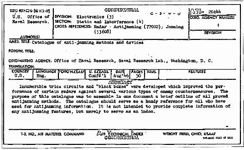
E0raRK?1OD(BICl<&) U.S. Office of Kaval Research.
AUTHOB(S)
j - </ - y. e@Kii?i®oKrirofliL
DIVISION: Electronics (3) • SECTION: static and Interference CO CROSS REFERENCES! Radar - Antijamming (77002); Jamming
(53608)
lAffi- 20(M ORIG. AGENCY NUAJOHl
E2 REVISION
AMEB. TITIE: Catalogue of anti-Jamming methods and devices
FORG'N. TITIE.
ORIGINATING AGENCY: Office of naval Research, Haval Research Lab. TRANSLATION:
Haahington, D. C.
COUNTRY U.S.
LANGUAGE fOttGNjCLAS* U. SJCLASS. DATE PAGES| IU.US. Confd'l Aug'l»6 50
FEATURES
Innumerable trie* circuits and "black boxes" were developed which improved the per- formance of certain radars against several various types of enemy countenEsaaurea. The purpose of this catalogue was to assemble in one document a brief outline of all proved antijamming methods. The catalogue should serve as a handy reference for all who have need for antijamming Information. It is not intended to provide complete Information of any antijamming features, but merely to servo as an Index.
T-2. KQ, AIR MATERIEL COMMAND /Sua' lECHNICAl UNDEX >NPIIIMOT0AI1
WRIGHT FIELD, OHIO. USAAF
AUTHOR(S):
tVJIDt liOl1\l:X~·{~:r-n:::;,~.:Jl..'ISe!i1 t;Ol:!;n.-t.t~e
OA: O;:'i:::.JZG cS: 1·!~\i'c.l nC:J~!'...'?©hD £';0.,,<:\1{":;J8k~.:~:r~?a1A", ,1;0 Go
Forelp TltIe:
OA No:
Previously cataloged under No: Translation No:
Subject DlYlsion, ~ Section:-:/'., .. A/·~...... _.-',-. ...., ••• /-. "J..-,p ,"
~~
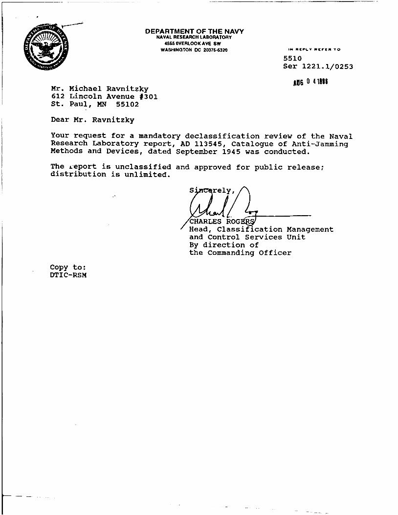
:~DEPARTMENT OF THE NAVY
NAVALRESEARCHLASORATORY4555 OVERLOOK AVE SW
WASHINGTON DC 20375-5320
5510Ser 1221.1/0253
Mr. Michael Ravnitzky612 Lincoln Avenue '301st. Paul, MN 55102
Dear Mr. Ravnitzky
A06 0 4111.
Your request for a mandatory declassification review of the NavalResearch Laboratory report, AD 113545, Catalogue of Anti-JammingMethods and Devices, dated September 1945 was conducted.
The ~:eport is unclassified and approved for pUblic release;distribution is unlimited.
CHARLES ROGHead, Classification Managementand Control Services UnitBy direction ofthe Commanding Officer
Copy to:DTIC-RSM
Related Documents